adaptive riser angle position reference system
TRANSCRIPT
United States Patent [19] Gay et al.
[54] ADAPTIVE RISER ANGLE POSITION REFERENCE SYSTEM
‘[75] Inventors: Tom A. Gay, Houston, Tex.; Gary L. Hartman, Fridley; Gunter Stein, New Brighton, both of Minn.
[73] Assignee: Honeywell Inc., Minneapolis, Minn.
[21] Appl. No.: 177,667
[22] Filed: Aug. 13, 1980
[51] Int. Cl.3 ..................... .. G06F 15/20; B63H 15/00 [52] US. Cl. .............................. .. 364/432; 114/144 B;
364/449 [58] Field of Search ..................... .. 364/432, 449, 460;
33/1 N, 1 H; 114/144 B
[56] References Cited -
' U.S. PATENT DOCUMENTS
3,121,954 2/1964 Foster ..................................... .. 33/1
, 3,148,653 9/1964 Shatto, Jr. et a1. .. 114/144 3,965,840 6/1976 Blumberg ........ .. ..‘114/l44B 3,974,792 8/1976 Burnell et al. .. 114/144 B 4,038,540 7/1977 Roberts . . . . . . . . . . . .. 364/728
4,044,473 8/ 1977 Crask 33/1 H X 4,051,350 9/1977 Parent ...... .. 364/432
4,071,821 1/1978 Harthill et al. .. 364/728 X 4,205,379 5/1980 Fox et al. .......................... .. 364/432
OTHER PUBLICATIONS
Triantafyllou, “The Design of a Dynamic Positioning System”, IEEE, CH1478-7/79/0000-0498, 1979. Dean, “A Riser Angle Positioning System (RAPS)”,
[11] 4,351,027 [45] Sep. 21, 1982
Paper No. OTC3755, Offshore Technology Confer ence, May 1980. NESCO Report SNl83-2A, Part I, “Dynamic Stress Analysis of the Mohole Riser System”, National Engi neering Science Company, Jan. 29, 1965. Harris, An Introduction to Deepwater Floating Drilling Operations, Petroleum Publishing Company, 1972 (pp. 128-139). Grimble, et al, “The Design of Dynamic Ship Position ing Control Systems Using Extended Kalman Filtering Techniques”, IEEE, CHl478-7/79/0000-0488, 1979. Primary Examiner—.lerry Smith Attorney, Agent, or Firm—Charles L. Rubow
[57] ABSTRACT An adaptive riser angle position reference system and method for determining the horizontal position of a marine vessel relative to an underwater wellhead from angular deviations from vertical of a riser between the vessel and the wellhead are disclosed. The system com prises sensors for determining deviation from vertical of the riser at positions proximate the wellhead and the vessel and a compensation ?lter for adaptively ?ltering signals indicative of the lower and upper riser angles in accordance with ?lter coef?cients which are deter mined by riser parameters. The ?lter coef?cients are established by riser parameter identi?cation means which effectively compares riser response, as indicated by the lower and upper riser angles, with the responses of a plurality of riser models, and selects ?lter coef?ci ents corresponding to the most accurate model.
15 Claims, 5 Drawing Figures
I i \30 DEPTH DATA BASE
L lNtTlALIZATlON 37 J
as __
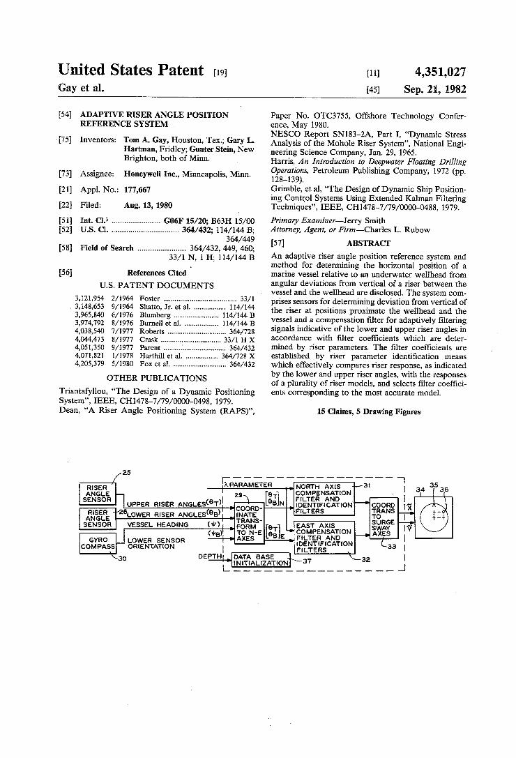
[IPARAMETER NORTH Axls “I31 1 35 mg“ I I 34 I as ANGLE 2; 9T COMPENSATlON [ SENSOR @ )1 \ e FILTER AND _ ]
UPPER RISER ANGLES T : coém} B N. IDENTlFtCATION "ggg?g 13,’ 31%; ‘ZGLOWER RISER ANGLES(9B)| {Ra/gas F‘LTERS To 1
l -
SENSOR VESSEL HEADING (w) , FORK‘, EAST Axis suacs N we)‘ TO N-E 3T] “'COMPENSATION A‘gg [Y
LOWER B E samurai L * COMPASS ORIENTATION FILTERS 33 I
‘ |
U.S. Patent Sep. 21, 1982 Sheet 1 of5 4,351,027
Ba. 1

US. Patent Sep. 21, 1982 Sheet 2 of5 4,351,027


US. Patent Sep. 21, 1982 Sheet4 of5 4,351,027
( INITIATE MAJOR CYCLE v
| CHECK FOR VALID DATA II]
] INPUT eTM,eBM, w, A [2|
I ROTATE 9TM,6BM TO NE MES 13]
I O
SELECT FILTER INDEX (ONE FILTER IN EACH AXIS IS COMPUTED EACH CYCLE)
X =SCRATCH VECTOR.
LAST FILTER IN
AXIS
SELECT MIN TJI) [i ITEMP=ARC MIN TJILJ)


'4,3 51,027 1
ADAPTIVE RISER ANGLE POSITION REFERENCE SYSTEM
BACKGROUND OF THE INVENTION
The invention herein described pertains generally to determining the position of a marine vessel, and more speci?cally to adaptive means for processing signals indicative of the deviation from vertical of a marine riser to produce an estimate of horizontal vessel posi tion. There is increasing interest in exploring for oil and
minerals on or beneath the ocean beds in deep water, producing oil and minerals from such locations, con ducting marine research in very deep water and main taining and servicing equipment used in connection with the foregoing activities. Such activities require the ability to rapidly and accurately ascertain marine vessel position relative to an underwater location of interest. High quality position information is also demanded in other speci?c applications in which it is required to maintain ?xed position of a ?oating marine vessel. A variety of schemes have been developed for deter
mining marine vessel position. Acoustic systems have been increasingly used because they do not require physical connection to the ocean bed or object of inter est, and because of their potential capability of produc ing accurate position information in very deep water. However, the quality of position indications produced by acoustic systems is generally dependent on acoustic paths having constant transmission characteristics. The subsea environment typically does not provide ideal acoustic transmission paths. Factors resulting in vari able transmission characteristics include re?ection and /or refraction of signals from thermal layers in the wa ter, scattering of signals from water borne particles and re?ection of signals from underwater structures. These factors may result in spurious indications of vessel posi tion or complete loss of position information for short periods of time. In addition, acoustic signals emanating from sources other than the position indicating system may cause spurious position determinations. These fac tors produce a severe acoustic signal transmission envi ronment having effects on signal transmission which are not presently susceptible of complete analysis. The un certainties in operation of an acoustic position indicat ing system are not acceptable in the most critical vessel positioning applications. Accordingly, it may be desired or required to have an alternative or backup system other than an acoustic system. Obviously, in critical applications such an alternative or backup system also must be capable of reliably and accurately indicating vessel position. One alternative system and technique which has been
used to determine the horizontal position of a marine vessel relative to an underwater wellhead is to sense the deviation from vertical of a marine riser, oil well drill string, or cable extending from the vessel to the well head or a location near the wellhead. For simplicity the remainder of the discussion will refer only to a riser, with the understanding that. the system or technique may actually involve a drill string, cable or other ?exi ble member suspended from the vessel. A signal indica tive of the angular deviation may be used in a system to display and/or control vessel position. Angular devia tion of the riser from vertical typically has been sensed by a sensor located near either the upper or the lower end of the riser. Such a scheme is satisfactory provided
15
20
25
30
35
40
45
55
65
2 that the riser acts in a predictable fashion. Riser dynam ics are reasonably predictable for shallow water depths. However, as the water depth increases, the measured angles become increasingly less a direct indicator of vessel position. US. Pat. No. 4,205,379 issued in the name of M. Fox,
et al discloses a version of a riser angle reference system which offers some improvement over conventional systems. It includes sensors for sensing the instanta neous vertical slope angles of the riser at both its upper and lower ends. The angle signals are ?ltered to remove higher order frequencies and combined in accordance with a position equation which compensates for phase lag at the lower sensor. Although such an approach is superior to one which utilizes a single riser angle, it is limited in capability to producing a position estimate based on only one assumed riser response for each pair of measured angles at any given depth. Such an assump tion is not valid in many instances. A long riser acts in a very ?exible manner and devi
ates substantially from a straight line between the vessel and the wellhead. It has various response modes ,de pending on excitation stimuli, riser parameters and other factors. The various modes result in different riser shapes, e.g., an s shape. The ?rst several lower order modes fall within the response range of a typical dy namic positioning system (i.e., a positioning system which utilizes thrusters to maintain vessel position). Accordingly, the various modes must be correctly ac commodated to achieve satisfactory position control.
Riser excitation stimuli include currents which differ substantially at different depths, and wind and wave action. There is a substantial delay between the time that vessel motion occurs and the time at which corre sponding motion appears at the lower end of the riser. Angular deviation at both ends of the riser is contami nated with higher frequency responses to wind and waves which are typically alternating in nature. Partic ularly in connection with wave action, the period of vessel movement is relatively short and the vessel is continuously driven a short distance either side of and then returned to its desired position. With reference to vessel position control, signi?cant energy would be required to attempt to oppose this action. Further, such operation is not required in most applications and would be grossly inefficient in terms of equipment operation and fuel consumption.
It has been found that the overall quality of position indication of a riser angle reference system can be much improved by detecting angular deviations at both the upper and lower ends of the riser and ?ltering the sig nals indicative of the angles in an adaptive ?lter whose coefficients are adjusted in accordance with a best ?t mathematical model of the riser selected from a plural ity of riser models. Accordingly, the useful position information re?ected in the angles can be extracted for any important riser mode while avoiding the complica tions caused by lag at the lower end of the riser and extraneous high frequency components at the upper end of the riser.
SUMMARY OF THE INVENTION
An adaptive riser angle position reference system in accordance with this invention basically comprises angle sensing means for producing signals indicative of deviation from vertical of the riser at its upper and lower ends. The angle signals are combined and sup

4,351,027 3
plied to a compensation ?lter which adaptively attenu ates various groups of frequency components. The ?lter coef?cients are automatically adjusted in accordance with riser parameters identi?ed by riser parameter iden ti?cation means which effectively compares the-riser response as indicated by the angle signals with a plural ity of riser model responses, and adjusts the compensa tion ?lter coef?cients in accordance with the model response which most closely approximates that of the riser. The output of the compensation ?lter may be supplied to a high pass ?lter, and a weighted sum of the angle signals may be supplied to a low pass ?lter whose output is summed with the output of the high pass ?lter to ‘obtain a estimated position signal. ‘ Accordingto the position referencing method of the
present invention, upper and lower riser angles are sensed and the angular information ?ltered in accor dance ,with ?lter coef?cients which are adaptively de termined by the riser parameters. The ?lter may be of a form which attenuates bands of frequency components at two center frequencies and frequency components above a multiple of one of the center frequencies. The attenuated signal and a combination of the angle signals may be passed through a high pass ?lter and a low pass ?lter respectively, and combined to produce an esti mated position signal. The ?lter center frequencies and other characteristics may be determined by comparing the riser response with responses of a plurality of riser models and supplying ?lter coef?cients based on the closest model. BRIEF DESCRIPTION OF THE DRAWINGS
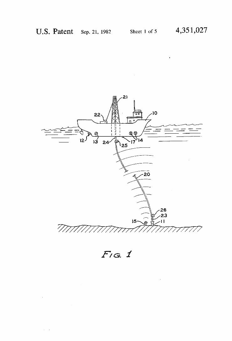
FIG. 1 is a schematic illustration of a marine vessel employing an adaptive riser angle position reference system in accordance with the present invention; FIG. 2 is a general block diagram of the adaptive riser
angle position reference system employed on the vessel of FIG. 1; FIG. 3 is a more detailed block diagram of the ?lter
concept and functional principles employed in the adaptive riser angle position reference system of FIG. 2; and FIG. 4 which includes FIGS. 4A and‘4B is a flow
chart of a preferred software ‘implementation of the signal processing portions of the adaptive riser angle position reference system of FIGS. 2 and 3.
DESCRIPTION OF THE PREFERRED EMBODIMENT
In FIG. 1, reference numeral 10 identi?es a ?oating marine vessel designed and equipped to drill for oil under the sea bed in very deep water, e.g.,'up to 6,000 feet. Such activity requires reliable, current and accu rate information as to horizontal position of the vessel relative to a subsea wellhead ‘identi?ed by reference numeral 11.
Vessel 10 is shown equipped with a dynamic position ing system comprising a main screw 12 and ?xed as muth transverse thrusters 13 and 14 respectively located fore and aft of the center of rotation of the vessel for maintaining the vessel in a desired position above the wellhead. For illustrative purposes, thrusters 13 and 14 are shown as tunnel thrusters. However, other types and con?gurations of propulsion units may be equally suitable. As is well known from various references, including previously noted U.S. Pat. No. 4,205,379 and U.S. Pat. No. 3,148,653 issued in the name of H. L. Shatto, J r., et al,, the propulsion units may be automati
10
25
4 cally controlled in response to signals derived from sensed location and heading of vessel 10. Heading can be sensed by means of a gyro compass, magnetic com pass, or other suitable heading sensor. Horizontal loca tion in two vertical planes may be sensed by various means, of which a free standing beacon acoustic system and a riser angle reference system are shown in FIG. 1. For simplicity, only the portion of the free standing beacon acoustic system for determining location along the fore aft vessel axis will be described. Location along an athwartship axis can be analogously determined. The beacon system comprises an acoustic beacon 15
which is located in a fixed positional relationship with wellhead 11. Beacon 15 may‘transmit an acoustic signal comprising a periodic tone of a known carrier fre quency. The acoustic signal is received by hydrophone apparatus 17 mounted on vessel 10. The hydrophone apparatus may include three hydrophone elements of which pairs of elements are located along orthogonal horizontal axes, one element being common to both axes.
The angular displacement of hydrophone apparatus 17 from a position directly over beacon 15 results in phase differences in the acoustic signal received by separate hydrophone elements. The magnitude of such phase differences is indicative of the horizontallocation of the vessel relative to the wellhead, and may be used
' to display and/or control vessel position in a known
30
35
45
55
60
65
manner. A digital phase determining system in accor dance with the foregoing description is disclosed in detail in U.S. Pat. No. 4,038,540 for a Quadrature Cor relation Pulse Detector issued July 26, 1977 in the name of J. L. Roberts, and U.S. Pat. No. 4,071,821 for Quad rature Correlation Phase Determining Apparatus issued Jan. 31, 1978 in the names of W. P. Harthill and J. L. Roberts. ‘ »'
Such a free standing beacon acoustic system offers many advantages in determining vessel position, espe cially in deep water. However, as previously indicated, acoustic systems are affected by the quality of the acoustic signal path between the beacon and the hydro phone, and may produce spurious’ position determina tions or fail to provide updated position determinations for short intervals of time under adverse conditions. Accordingly, in circumstances in which position infor mation is critical, it is desirable or necessary to have an alternative or backup position determining system. One such critical circumstance occurs when the ves
sel is connected to the wellhead through a marine dril ling riser'as identi?ed by reference numeral 20. Such a riser is used to provide a return ?uid ?ow path between the well bore and the vessel and to guide a drill string to the wellhead. For deep water operation, the riser is maintained in tension by means of a derrick 21 and tensioning apparatus 22. ' As is apparent, the angular position of riser 20 relative
to vertical is generally indicative of the position of ves sel 10 relative to wellhead 11. However, as illustrated in FIG. 1, the riser generally does not follow a straight line between the vessel and the wellhead. Riser re sponse in general, and particularly its dynamic response, are very complicated as briefly discussed in Harris, An Introduction to Deep‘ Water Floating Drilling Operations, PetroleumPublishing Company, 1972, pages 128 et seq. Static factors which affect riser response include ten sion and the weight of the drilling mud, drill pipe and the riser. Dynamic factors' include wave and current loading (vortex shedding), Variations in riser tension

4,35 1,027 5
and vessel motion due to wind, waves and current. A lower ?exible joint or ball joint, as identi?ed by refer ence numeral 23, is typically used in a marine riser sys tem to minimize bending moments and stress concentra tions. In deep water operations or in severe sea condi tions an upper ball joint as identi?ed by reference nu meral 24 is also included in the riser‘. Deviation from vertical of the riser can be sensed by
means of a riser angle sensor. Such sensors are commer cially available from a number of manufacturers, includ ing Honeywell Inc. and Delco Electronics Div., Gen eral Motors Corp. In the apparatus of FIG. 1, upper and lower riser angle sensors identi?ed by reference numer als 25 and 26 respectively are provided. These sensors are attached to the riser proximate the upper and lower ball joints. A common type of riser angle sensor com prises a pendulum which is free to swing about a verti cal axis. Means is provided for sensing the pendulum position in orthogonal vertical planes and producing corresponding pendulum position signals. These signals may be processed for transmission in the sensor and transmitted to the vessel through any suitable transmis sion link. In the present application where loss of an acoustic link is of concern, these signals may be trans mitted through an electrical cable not illustrated in FIG. 1 associated with the riser. With reference to the general block diagram of FIG.
2, the desired outputs for a position indicator or an automatic position control system for a vessel of the type shown in FIG. 1 are in terms of fore-aft or surge displacement, designated as X, and athwartship or sway displacement, designated as Y. Upper and lower riser angle sensors 25 and 26 are generally not oriented to the same coordinate system, and neither is generally ori ented to a coordinate system corresponding to the surge-sway axes of the vessel. In order to combine the angular information provided by sensors 25 and 26 it is necessary to transform the angle signals to a common coordinate system. The transformation is accomplished as indicated by block 29 using the upper riser angles 07, the lower riser angles 05, the vessel heading \{1 and the lower sensor orientation 111B. Vessel heading is deter mined from a gyro compass 30 or other suitable heading sensor located on the vessel.
Information as to lower sensor orientation may be known or directly measurable in some instances. In other- instances, due to uncertainties in landing a blow out preventer stack and connected riser on a subsea wellhead, the heading of the lower riser angle sensor may not be known accurately in earth referenced coor dinates.- However, the heading of the lower riser angle can be deduced from angular responses indicated by the upper and lower riser angle sensors. One suitable pro cess involves introducing a delay into the upper sensor signal, passing the signals through a band pass ?lter, and performing a least squares error comparison of the sig nals. .
The output of the coordinate transformation block comprises information as to deviation of the upper and lower riser from vertical in a north-south (hereinafter, north) plane and deviation of the upper and lower riser from vertical in an east-west (hereinafter, east) plane. The angular deviation information in the north plane is supplied to a north axis compensation ?lter and identi? cation ?lters identi?ed by block 31. Similarly, the angu lar deviation information in-the east plane is supplied to an east axis compensation ?lter and identi?cation ?lters identi?ed by block 32. The compensation and identi?ca
l0
15
20
25
30
35
40
45
50
55
65
6 tion ?lters represent the riser in the form of a modal model based on a partial differential equation which describes the physics of the riser. The basic modeling equation is a fourth order equation
where ' EI=riser beam stiffness
x=lateral riser de?ection h=height T=riser tension an: apparent riser mass/unit length (i.e., combined
weight of riser and drilling mud minus buoyancy) f = distributed forces on riser
The Filter blocks 31 and 32 are also supplied with a weighting factor A used to adjust the weighting to be attributed to the upper and lower riser angles for a desired steady state relationship. This permits the low frequency relationship between the upper and lower riser angles to be adjusted independently of any system loop gain. ‘ The outputs of ?lter blocks 31 and 32 represent vessel
displacement along north and east axes, respectively. These outputs are supplied to a second coordinate trans formation block identi?ed by reference numeral 33 which transforms them into a surge-sway coordinate reference system usable by the vessel position indicating and/or control system. As shown for illustrative purposes, outputs X and Y
of transformation block 33 are supplied to a position display or indicator 34. In one form, indicator 34 may comprise a cathode ray tube in which the center of the screen represents vessel location, triangular symbol 35 indicates a reference direction (e.g., north) relative to vessel heading represented by the top of the CRT screen, and diamond symbol 36 indicates location of the wellhead relative to the vessel along orthogonal hori zontal axes.
Reference numeral 37 identi?es a data base initializa tion block in which a data base containing certain ?lter coef?cients used in the identi?cation and compensation ?lters is established. The ?lter coef?cients are deter mined by operating depth which is manually entered by an operator. Each of the ?lter blocks 31 and 32 performs identical
operations as indicated in FIG. 3. Only ?lter block 31 will be further described. The applicants have deter mined that the riser can be satisfactorily modeled by means of a ?fth order compensation ?lter with four parameters that are adjustable on the basis of frequency and damping parameters of the riser. The compensation ?lter has the form of two notch ?lters plus a low pass ?lter, and can be represented by the function
r r 1W where the ?rst parenthetical expression represents a notch ?lter centered on a frequency ml, the second parenthetical'expression represents a notch ?lter cen tered on frequency w; and the third parenthetical ex pression represents a low pass ?lter having an upper cutoff frequency of 3m‘.

4,351,027 7
Information as to the upper and lower riser angles is weighted by factors of 0.7 and 0.3, respectively, as indi cated by blocks 40 and 41 and summed to'provide an input to a compensation ?lter as previously described identi?ed by block 42. Although a specific linear weighting relationship is shown, other linear or nonlin ear relationships are satisfactory and may be preferred vunder certain conditions.
Information as to the upper and lower riser angles is also weighted by factors of l-l» and 7t, respectively, as indicated by blocks 43 and 44 and summed as indicated at 45. The outputs of compensation ?lter 42 and sum ming point 45 are supplied to a complementary ?lter 46 in which components of the compensation ?lter output above a predetermined frequency and components'of the output of summing point 45 below a predetermined frequency are combined to provide an estimated vessel position along a north axis. The variable parameters of compensation ?lter 42,
m1, an, E1 and 52 are varied in accordance with riser parameters. However, it has been found that the ?lter parameters do not need to be continuously adapted ‘to the riser parameters. Furthermore, for. a given depth, the most signi?cant riser parameter is the damping coef ?cient. If this can be determined to one of several inter vals, then a compensation ?lter having appropriate characteristics can be achieved. This suggests a simple discrete minimization algorithm for each interval. Ac cordingly, the riser parameter identi?cation block 50 includes a plurality of Kalman ?lters 510-510, each covering an interval of the damping parameter. Each Kalman ?lter is a 12 state ?lter. The Kalman ?lter coef ?cients A,-, band K,- are indexed with riser parameters. As indicated in the discussion of FIG. 2, the data base containing certain ?lter coef?cients is determined by operating depth and is established during initialization of the data base. Each ?lter effectively processes the riser angle sig
nals so as to compare riser response with responses of a plurality of riser models, and generates a likelihood function as indicated by blocks 52a-52c indicative of how closely each model approximates the response of the riser. The minimum likelihood function indicates the interval containing the riser parameters. The minimum likelihood function is selected by selection logic as indi cated at block 53 to produce a ?lter index i*. The ?lter index is used in conjunction with a lookup table 54 to adjust coef?cients of compensation ?lter 42.
Signal processing for the adaptive riser angle position reference system is preferably accomplished through a software routine implemented on a digital computer. A ?owchart for a suitable software routine is shown in FIG. 4 in which the principal real-time tasks which must be executed each cycle are set forth in numbered boxes. A brief description of each principal real-time task and certain other necessary tasks is set forth below. The ?lter and identi?er software contains a set of
initialization tasks and a set of real-time tasks. The ini tialization tasks must be performed prior to entering the real-time operation and may be required by operator input at any subsequent time. The real-time tasks con tinue uninterrupted cyclically until the system is shut down or reset. - ' - -
The initialization tasks require knowledge and entry of water depth to de?ne the set of identi?cation and compensation ?lters to be used. The set of ?lters thus de?ned covers the range of riser frequencies likely to be encountered at the entered depth. A change in water
0
20
25
35
40
45
50
55
60
8 depth requires a re-initialization by the operator. The total data set of ?lter coef?cients for the entered depth is automatically stored in a scratch memory. An opera ble embodiment was designed with 14 channels, as shown in Table 1. For purposes of this description, a channel comprises an identi?cation ?lter and a compen sation ?lter corresponding to a speci?c set of riser fre quency and damping parameters. These channels are used for both north and east axis identi?cation and com pensation. The initialization de?nes number of channels
(NCHAN) and the starting (IS) and ending (IE) chan nel index for the indicated depth as shown in Table l. The constant used in the complementary ?lter is
where a is generally the frequency at which the pre dominant influence of the inputs to the complementary ?lter on its output ‘shifts between the input provided by the compensation ?lter and the input provided by sum ming point 45. The ?lter coef?cients for a discrete form of complementary ?lter (see real-time Task 7) are:
mcl = (2 T a)/(2 + a)
I The HI measurement matrix (see Table 3) contains a . single element with depth dependence that must be computed.
HI = —2 0.28 —2 0.28 —2 0.28 —2 —0.28 9 —l.l8312:1—2 0
2 —0.28 —2 0.28 2 —0.28 —2 —0.28 l —0.l40 0
The parameters .5, TJSW, IMIN (l) and IMIN (2) must be de?ned, and ?lter variables TJ (1,1), XPI(I,J), VI(I,J), XPC(J), UP(J), W(J) and UPWO) must be initialized at zero.
The set of real-time tasks which are executed each cycle are shown in ?ow chart form in FIG. 4. The flow chart indicates the sequencing of tasks and the corre sponding equations. The inputs and outputs are de scribed in Table 2. The variables are listed and de?ned in Table 3 and the tasks are referenced by numbers in the flow chart. Task l-—-Check selection discretes for riser angles and
heading angle. If valid data available continue, other wise set bad data ?ag and wait for next cycle to recheck validity. Task 2—Input data. Obtain the upper (01M) and
lower (03M) riser angles, the vessel heading sine and cosine, the two set points for surge and sway and the A parameter from the input processor. Task 3—Rotate all riser angle measurements to
north-east axes for identi?cation and compensation. Input: OTMQ), 0BM(J)1, sin xiv, cos 111, rpm Output: 07(1), 05(1) ‘ The bottom angle is rotated by \URA
9191 9am 982 91am
} =[ cos lIJRA‘Sih \IJRA —sin llIRA cos um

4,351,027 9
The top angle is rotated by vessel heading to north east coordinates
911m 91342
From this point forward, a completely identical set of tasks exists for the north and east axes. To identify the variables in each axis, they will be indexed by the argu ment “J” where J =l indicates ‘the north axis and J =2
cos ll! sin ill —sin ill cos \11
i the east axis. The measurement vector is defined as
[2:22 ‘
where 07(J)=Jth axis top angle 63(J)=Jth axis bottom angle Task 4—-Update identi?cation ?lters. V >
Input: Y(J), 2X 1 vector of top and bottom riser angle for each axis .
Output: TJ(I,J), the‘ likelihood function for the I“ ?lter of axis J , .
At each depth range there are a number of identi?ca tion ?lters to be evaluated. The number (NCHAN) is de?ned in the initialization as a function of water depth. The matrix equations are:
x=XPI(I,J)(update state) VI(I,J)=Y(J) —HI-x(compute residual) XPI(I,J)=AI(I)x+GI(I)*VI(I,J)(predict state)
I=channel index ranging from IS to IE as de?ned in initialization _
J =axis index, ranging from 1 to 2 X: l2-component state-scratch vector XPI(I,J) = l2~cornponent residual VI(I,J) =2-component residual AI(I) = 12 X 12 riser model matrix indexed by channel number .
GI(I)=12><12 Kalman gain matrix indexed by chan nel number . '
HI=2><12 measurement matrix >
R(I)=weighting matrix for ?lter residuals indexed by channel number
5 = deweighting-constant TJ(I,J)=Scalar likelihood function for ?lter I; Axis J The matrixes AI(I), 61(1) and R(I) can be stored in
any convenient fashion that allows them to be appropri ately indexed. The above ?lter calculations must be repeated for up to four indexes as de?ned by ‘channel index for each axis. '
Task 5—Select channel corresponding to the mini mum likelihood function. " '
Input: TJ(I,J), I=IS .} . . IE, J-1,2, the likelihood function values for this cycle _
Output: IMIN(J), the channel number of the smallest likelihood function for ~the axis J I
Set ITEMP(J)=the I corresponding tothe minimum TJ(I,J) for each J, where I is the same set of indexes (up to four) used in Task 4. An initial value of IMIN(J) was de?ned in the initialization section. A difference of at least TJ SW must exist between the value .of TJ(I MIN(J)',J) and the 'value of TJ(ITEMP(J),J) before IMIN(J) is updated. If this threshold is satis?ed, then set IMIN(J)=ITEMP(J).
.20
25
30
35
45
55
65
v10 Task 6-Execute compensation ?lter for parameter
set de?ned by IMINO). Input; Y(J), 'IMINU) Output: XHATU) (?rst state in compensation ?lter) The compensation ?lter is ?fth-order, de?ned by the
following matrix equations: Set I=IMIN(J) X=XPC(J) (left from last cycle, zero initially) U(J)=[0.7, 0.3]Y(J)(a vector dot product) XPC(J)=AC(I)*X+-GC(I)*(U(J)+UP(J)) XHAT(J)=HC"X '
UP(3)=U(J) '
where .
XPC(J)=5-component state for compensation ?lter U(J)=Scalar input to ?lter for axis J
v UP(J)=previous value of U(J) '
AC(I)=5 X 5 compensation ?lter plant matrix in dexed by minimum channel
GC(I)=5X1 compensation gain matrix indexed by minimum ‘channel
X=5-component scratch vector HCéSXI output matrix=[l,0,0,0,0] Task 7—Execute complementary ?lter Input: XHATQ), Y(J) Output: XCON(J) The equations are ~
where UW(J)=XLF(J)—XHAT(J) can be a scratch vari able
"UWP(J)=UW(J) at previous step time A=input weighting variable The output calculation is: XCON(J) = XHATU) + W(J) Task 8—Convert control signal to surge-sway axes. Input: XCON(J), STPT(J), simll, cosill Output: CMMD(J)' Rotate XCON to surge sway axes
X0) _ XCON(1) [X(2)] _[ ] [XCON(2) where X is a scratch vector. Then
cos \{4 sin all —sin iii cos \ll
CMMD(1) _ X(l) CMMD(2) _ X(2)'
TABLE 1 CHANNELS AS A FUNCTION OF WATER DEPTH
Nominal Operating Number of Channels Indexes (Ft) Range (Ft) (NCHAN) (IS, IE)
0 0-750 None .(No Filters) 0, 0 1000 750-],250 Compensation Filter Only l, l 1500 l,250-2,250 2 2, 3v 3000 2,250-3,750 3 ' ' 4, 6
4500 3,7SO-5,250 4 7, 10 6000 5,2S0-6,750 4 ll, 14

4,351,627 ‘ 11 12
TABLE 2 TABLE 3-continued
IDENTIFIER/FILTER INPUTS AND OUTPUTS LIST OF VARIABLES I 7 I112 ts Variable De?nition Units
. 0TM(1) Top, riser angle in sensor 5 WCl Filter coefficients in
} axes (referenced to surge- } ' ' 0TM(2) sway vessel axes). WC2 complementary ?lter 0BM(1) Bottom riser angle in CMMD(J) Output in surge-sway axes % wd
} sensor axes (referenced to 0BM(2) ‘ north-east axes). ~. ' ' . - .
tllRA ‘ Orientation of bottom angle with 10 Although a preferred embodiment of the applicant’s ‘ respect to north-88$ coordinates adaptive riser angle position sensor and position sensing
Sm‘? Sm. °f Vessel headmg. method have been illustrated and described in detail, Cosll: Cosine of vessel heading . . . . . H wam. depth numerous variations and alternative embodiments in A Weighting parameter for steady-state accordance with the teachings herein will be apparent
Control Of upper and lower riser angles 15 to those skilled in the art. For example, it is apparent m that riser models and modeling techniques other than
CMMD(D su‘ge a.“ reference the speci?cally described embodiment and technique CMMD(2) Sway axis reference . may be employed. The scope of coverage sought on this
. - invention is not to be limited to the disclosed embodi
TABLE 3 20 ment, but only by the terms of [the appended claims. LIST OF VARIABLES . The embodiments of the invention in WhlCh an exclu
. . sive property or right is claimed are de?ned as follows: Variable De?nition ' Units . . . . ; ,
_ 1. An adaptive riser angle position reference system ;S ‘83x3?! 31:25:33?“ 7 _ for determining the horizontal ‘position of a marine IE Endinggchmmel index >_. 25 vessel supporting a riser which extends between the J Axis index (i or 2) - vessel and a subsea ‘wellhead, comprising: IFLAG Set to 1 to indicate real-time code executing -j a ?rst vertical angle sensor for producing a lower NCHAN Nu'i‘ber °f ‘Ehannels be‘ng °°mpmed _ " angle signal indicative of deviation from vertical of a Reciprocal time constant for l/sec h l . . . h 1111 _
complementary ?lter t e ower riser at a point proximate t ‘e we ead, acl Coefficients to de?ne a as 30 a second vertical angle sensor for producing an upper 2} f f d h angle signal indicative of deviation from vertical of
ac a unctiono ept » ' - ' - '
A weighting parameter form], and bottom __ the upper riser at a point proximate the marine riser angles vessel; _ ~ , I . _
ipRA Orientation of lower riser angle sensor with rad _ "compensation ?lter means having ?lt'er characteris
¢ ifspet‘itlro girth-east “es mi- 35 tics which are variable in accordance with ?lter " esse ea ing ' ' ' - .
e Deweighting constant of likelihood function I/sec . coef?clents suPgheqtfherFto’ . , d t OTM lvleamement oftop riser angle (two %_wd riser parameter 1 enti ication means ,connecte 0
components) _ receive the lower and upper angle signals and oper OBM Measurement“ bottom riser angle (two % Wd able to determine a riser model whose response
components ‘ ' ' ' 1'1‘ -
0.1. Top riser angle in northeast coordinates % wd 40 approximaftes that offf the riser and_to supply co _ e 63 Bottom rise, angle in nonhmst % wd sponding lter coe icients to said compensation
coordinates _ ' \ ?lter means; : '
H Water depth ft ?rst transfer means for receiving the lower and upper YO) yam" °f‘°P and b°"°m ' % wd angle signals and supplying corresponding signals
ax _ - ‘ n
x Scratch vector used in comma?ons 45 (to, said compensation filter means, whereby the XPI(I,J) State vector for identification ?lters output of said compensation ?lter means is indica VI(I,J) Residual vector for identi?cation ?lters tive of V6886] position; TJ(I,J) Likelihood function , utilization means; ‘and AI(I) Riser model matrix for identi?cation ?lter ' ' - - - Gm) Kalman gain matrix for identi?cation ?lter second transfer means for receiving the output of said HI Measurement matrix for identi?cation ?lter 50 Fiompe'nsatlon_ ?lter: means ‘and supQlymg ‘coil-e‘ R(I) Weighting matrix for identi?cation ?lter sponding position information to said utilization EMF relsllduallsi _ _ I _ _ _ means, whereby said utilization means is opera
" (J) c an.” mde‘ .mm‘m'zmg hkehhmd ble to indicate horizontal vessel position relative function for axis J
IMIN(J) Channel index minimizing likelihood _ . to the W§>l1h¢a¢ - _ _ function and satisfying threshold. 55 2. The position reference system of claim 1 wherein:
gill?” ghreshold Patfameteriln selectinsfllMlm-l) a third transfer means is connected to receive the tate vector or comp ementary i ter ' -
U(J) Input to complementary filter. Combination % wd lower and upper af‘gk fslg-nals’hand 1_S operable to v I of upper and lower riser angler I produce a ?rst weighted sum t ereof, and
UP(J) Value of U(J) ‘at previous time step said second transfer means includes a complementary AC(I) Riser model matrix for compensation ?lter 60 > ?lter for attenuating low frequency components in Gem Ga‘“ mam‘f“ °°mPe“Sa“°'} mm the output of said compensation ?lter, attenuating HC .. Output matrix for compensation ?lter h. h f ' . - t . ‘th f t . ht d XHAT(J) Output of compensation ?lter lg requency componen s m us wclg e XLF(J) Combination of upper and lower riser angle Sum Of the lower and upper angle signals, and 99m
used to set steady-state reference bining the resultant signals to produce the position XCONU) O‘I'P“t °f °°mP1emenmY mt" 65 information which is supplied to said utilization W(J) - State for complementary ?lter m e a n s ' ;. . -
UW(J) Input to complementary ?lter (scratch ' quantity) '
UWP(J) Value of UW(J) at previous time step
3. The position reference'syste'm of claim 2 wherein said third transfer means includes manually adjustable

4,351,027 13
means for weighting the lower and upper angle signals by complementary factors.
4. The position reference system of claim 1, 2 or 3 wherein said riser parameter identi?cation means com prises:
processing means for comparing the lower and upper angle signals with corresponding angular responses of a plurality of riser models and computing a like lihood function for each of the model responses:
selection logic for selecting the likelihood function corresponding to the model having a response which most closely approximates that of the riser; and
a lookup table for supplying to said compensation ?lter means ?lter coef?cients corresponding to the selected likelihood function.
5. The position reference system of claim 4 wherein said processing means comprises a plurality of Kalman ?lters.
6. The position reference system of claim 5 wherein said compensation ?lter comprises: means for attenuating a ?rst band of frequencies cen
tered on a ?rst frequency in the signal supplied by said ?rst transfer means;
means for attenuating a second band of frequencies centered on a second frequency in the signal sup plied by said ?rsttransfer means; and
means for attenuating frequencies above a predeter mined multiple of the ?rst frequency in the signal supplied by said ?rst transfer means.
7. The position reference system of claim 6 wherein said ?rst transfer means includes means for weighting the lower and upper angle signals by complementary factors and summing the resultant signals.
8. The position reference system of claim 7 wherein the lower angle signal is weighted by a factor of approx imately 0.3 and the upper angle signal is weighted by a factor of approximately 0.7.
9. In a marine vessel position indicating system, a method for obtaining a signal indicative of the horizon tal position of the marine vessel relative to an underwa ter wellhead from deviations from vertical of a riser extending between the vessel and the wellhead, com prising:
producing lower angle signals indicative of deviation from vertical of the riser at a position proximate the wellhead;
producing upper angle signals indicative of deviation from vertical of the riser at a position proximate the marine vessel;
combining the lower and upper angle signals; determining riser parameters from the lower and
upper angle signals; ?ltering the combined signals in accordance with
?lter characteristics which are determined by the riser parameters; and
utilizing the ?ltered signals to indicate vessel position. 10. The method of claim 9 including the further steps
of:
10
20
25
30
35
45
55
65
14 producing a ?rst weighted sum of the lower and
upper angle signals; attenuating high frequency components in the ?rst
weighted sum; attenuating low frequency components in the ?ltered
signals; and combining the signals resulting after foregoing atten
uating steps to produce the signal utilized to indi cate vessel position.
11. The method of claim 10 wherein the step of ?lter ing the combined signals comprises:
attenuating a band of frequency components centered on a ?rst frequency:
attentuating a band of frequencies centered on a sec ond frequency; and
attenuating frequency components higher than a pre determined multiple of the ?rst frequency.
12. The method of claim 11 wherein the predeter mined multiple is approximately 3.
13. The method of claim 9, 10 or 11 wherein the step of determining riser parameters comprises:
processing the upper and lower angle signals through a plurality of Kalman ?lters corresponding to dif ferent riser model responses;
determining a likelihood function corresponding to each of the model responses;
selecting the likelihood function corresponding to the model whose response most closely approximate that of the riser; and
adjusting characteristics of the ?ltering applied to the combined signals in accordance with predeter mined ?lter coef?cients corresponding to the se lected likelihood function.
14. The method of claim 13 wherein the step of ad justing ?ltering characteristics includes adjusting the ?rst and second frequencies on which the ?rst and sec ond attenuated bands of frequency components are respectively centered.
15. The method of claim 14 wherein: the step of producing lower angle signals comprises producing ?rst and second lower angle signals indicative of deviations from vertical of the riser in two orthogonal vertical planes;
the step of producing upper angle signals comprises producing ?rst and second upper angle signals indicative of deviations from vertical of the riser in two orthogonal vertical planes;
the ?rst and second upper angle signals and the ?rst and second lower angle signals are transformed into signals in a common coordinate system;
the ?rst lower and upper signals are weighted by complementary factors and summed to produce a second weighted sum;
the second lower and upper angle signals are weighted by complementary factors and summed to produce a third weighted sum; and
the second and third weighted sums are ?ltered and the ?ltered signals utilized to indicate vessel posi tion in a horizontal plane.
* * * * i‘

UNITED STATES PATENT OFFICE
CERTIFICATE OF CORRECTION PATENT NO. : 4,351,027
DATED ; September 21, 1982
INVENTOR(5) I TOM A. GAY, et a1
It is certrfred that error appears in the above-rdentrfied patent and that sard Letters Patent are hereby corrected as shown below'
Title page, lefthand column, after "Assignee:
Honeywell Inc. , Minneapolis, Minnesota,"
add ——-and Exxon Production Research
Company, Houston, Texas--.
Signed and Scaled this Fourteenth D a y Of December I982
|SEAL| Arrest:
GERALD l. MOSSINGHOFF
Ann-ring Officer Commissioner of Parents and Trademarks

UNITED STATES PATENT OFFICE
CERTIFICATE OF CORRECTION PATENT NO. : 4,351,027 DATED ; September 21, 1982
INVENTORtS) : TOM A. GAY, et a1
It is certi?ed that enor appears In the ab0ve—|dent1fied patent and that Sam Letlers Patent are hereby corrected as shown below;
Column 14, line 28, _ Claim 13 — third paragraph, the word "approxlmate"
should be ——approximates-
Signed and Scaled this First D a y ‘0’. February 1983
(SEALI Amsr:
GERALD J. MOSSINGHOFF
Ant-‘ting Officer Commissioner of Patents and Trademarks