adaptive power module spec (369583) - lutron electronics€¦ · · 2017-01-04din rail power...
TRANSCRIPT

® Specif icat ion Submittal page
Job Name:
Job Number:
Model Numbers:
Adaptive Power Module HomeWorks QS Phase Adaptive Fixture Controller
369583e 1 12.14.16
Adaptive Power ModuleThe Adaptive Power Module family is a group of modular products for the control of lighting loads. This document describes the following product: Adaptive Power Module (model LQSE-4A-D)
Features
•AdaptivePowerModulescanbeusedina HomeWorks QS system.
•Automaticallyselectsleadingedgeortrailingedge dimming for incandescent/halogen, electronic/magnetic low voltage and neon / cold cathode light sources.
•ControlsdimmableCFL/LEDloads.RefertoLutronP/N 048478 on www.lutron.com for compatibility with dimmableCFL/LEDlightsources.
•RTISSEquippedtechnologycompensatesforincomingline-voltagevariations(upto±2%changeinfrequency/second)suchaschangesinRootMeanSquare(RMS)voltage,frequencyshifts,harmonicsandlinenoise.
LQSE-4A-D
Notes: 1 See"OutputZoneRatings"in“Specifications”section,forspecificloadtypesratings.
H
M
L
LQSE-4A-D
DIN
Rai
l Pow
er M
odul
e
230 V~ 50 / 60 Hz 10 A www.lutron.com +44.(0)20.7702.0657
CCI
500 W Max 800 W Max 500 W Max 500 W Max
Zone 2Zone 1 Zone 3 Zone 4
Input
Hi Temp
Prog
Power
Opt1
Opt2
Opt3
DefOption
System Example
•RTISS-TEoperatesonthetrailingedgeoftheACsine wave. This allows for true instantaneous voltage compensation.
•Unitis12DINmodules(216 mm) wide.•Providesairgapoff(whenallzonesareoff).•Integralprotectionforcommontemporaryover-
current and over-voltage conditions.•LEDsonfrontofunitprovidediagnosticinformation.•IncludesQSlinkforseamlessintegrationoflights
and controls.
MU
X
CO
M
MU
X
QS
Def
Opt1
Opt2
0-10 V Power ModuleLQSE-4T10-D230 V~ 50/60 Hz 50 mAwww.lutron.com +44.(0)20.7680.4481
1 2 3 4Outputs 230 V~ 10 AX each
Zone 1 Zone 2 Zone 3 Zone 4
Option
L N
µ
Z096
Opt3
CC
I
CCI
CO
M
0,5 N•mAll Others
8 mm1,2 N•mMains Only
Input
Hi Temp
Program
Power
H
M
L
Zones0-10 V-50 mA
Up
H
M
L
LQSE-4A-D
DIN
Rai
l Pow
er M
odul
e
230 V~ 50 / 60 Hz 10 A www.lutron.com +44.(0)20.7702.0657
CCI
500 W Max 800 W Max 500 W Max 500 W Max
Zone 2Zone 1 Zone 3 Zone 4
Input
Hi Temp
Prog
Power
Opt1
Opt2
Opt3
DefOption
QS Link
HomeWorks QS Power Module
Adaptive Power Module
GRAFIKEye QS
QSContactClosureInterface
HomeWorks QS Panel
seeTouch QS Wallstation
EmergencyContactClosureInput
Upto100total QS devices
220–240 V~ ControlPower
800 W Adaptive load1
500 W Adaptive load1
500 W Adaptive load1
500 W Adaptive load1

® Specif icat ion Submittal page
Job Name:
Job Number:
Model Numbers:
Adaptive Power Module HomeWorks QS Phase Adaptive Fixture Controller
369583e 2 12.14.16
SpecificationsAdaptive Power Module
Power
•220–240V~50/60Hz•10Amaximumtotalinputcurrent•LightningstrikeprotectionmeetsANSI/IEEEstandard62.31-1980.Canwithstandvoltagesurgesofupto 6 000 V and current surges of up to 3 000 A.
Standards
•IEC/EN60669-2-1•CEmarked•LutronQualitySystemsregisteredtoISO9001.2008
Environment
•SeeMounting onpage4forthermalspecifications•Relativehumidity:lessthan90%non-condensing•Forindooruseonly
Output Zone Ratings
•No Deratingisrequiredifalltheconditionsbelowaremet: –Calibrationpointmaximumis70ºC –Roomambienttemperatureisbetween0ºCand30ºC –Panelambienttemperatureisbetween0ºCand50ºC
•100 W Deratingisrequiredonallzonesforasinglemoduleinasinglenon-ventilatedDINenclosureif: – The room ambient temperature is between 30ºCand40ºC.
•200 W Deratingisrequiredonallzonesformultiple rownon-ventilatedDINenclosureif: – Theroomambienttemperatureisbetween30ºCand40ºC.
Output Zone Ratings (continued)
•Eachzonehasnominimumloadrequirement.
•Automaticallyselectsleading-edgeortrailing-edgedimmingorcanalsobemanuallyconfiguredforaspecificloadtype.
•Internalrelayprovidesanairgapoffwhenallzonesare off.
•Oneloadtypeperzone.
•Outputmustnotbeusedtocontrolreceptacles.
• Output must be directly connected to the load. ContactLutronforapplicationswithloadsidebreakers.
•Runaseparateneutralforeachloadcircuit.Acommon neutral connection is not recommended.
•MaximumwirelengthbetweentheEnergiSavrNodeunit and the load must be less than 30.5 m.
•UnitmaybepoweredbyGroundFaultInterrupter(GFI)orResidualCurrentCircuitBreakerwithOverload(RCBO)protectedcircuitifrequired.Loadcircuitwiring(from breaker to unit to load) must be run in its own non-metallic conduit, or nuisance tripping may occur.
•Forapplicationsrequiring0–10 V- control, use Ten VoltInterface(GRX-TVI)ortheQSNE-4T10-D.
•Forapplicationsrequiringhigherwattageratings,useapowerbooster(NGRX-PB,NGRX-ELVI,NGRX-FDBI).
Each zone is rated for the following wattage and load typesA, B:
Load TypeZone 1 Rating Zone 2, 3 and 4 Rating (per zone)
No Derating100 W Derating
200 W Derating No Derating
100 W Derating
200 W Derating
Incandescent/Halogen 800 W 700 W 600 W 500 W 400 W 300 W
Electronic Low Voltage 800 W 700 W 600 W 500 W 400 W 300 W
Magnetic Low VoltageD 800 VA (600 WC) 700 VA (525 WC) 600 VA (450 WC) 500 VA (375 WC) 400 VA (300 WC) 300 VA (225 WC)
Neon/ColdCathodeD 800 VA (600 WC) 700 VA (525 WC) 600 VA (450 WC) 500 VA (375 WC) 400 VA (300 WC) 300 VA (225 WC) A AdditionalloadtypeoptionsareavailableintheQuantumsoftwaresuite,somemayrequireaninterface.ContactLutronfordetails. B RefertoLutronP/N048478onwww.lutron.comforcompatibilitywithdimmableCFL/LEDlightsources. C Actual lamp wattage. D OnlyuseironcoretransformersintendedforusewithanelectronicswitchordimmerperClause8.3ofIEC/EN60669-2-1

® Specif icat ion Submittal page
Job Name:
Job Number:
Model Numbers:
Adaptive Power Module HomeWorks QS Phase Adaptive Fixture Controller
369583e 3 12.14.16
Specifications (continued)
Terminals (Torque,wiregauge&typeratings)
•Mainswiring:0.6N•m 1.0 mm² to 4.0 mm²
(single wire, solid or stranded) 1.0 mm² to 1.5 mm² (two wires, solid or stranded)
• Zonewiring: 0.6N•m 1.0 mm² to 4.0 mm²
(single wire, solid or stranded)
• CCIwiring: 0.6N•m 0.5 mm² to 4.0 mm² (single wire, solid or stranded)
• QSLink: 0.6N•m 0.5 mm² to 4.0 mm²
(single wire, solid or stranded) 0.5 mm² to 1.0 mm²
(two wires, solid or stranded)
Out of Box Functionality
This section describes the default functionality when theunitisfirstinstalled.
Emergency Contact Closure Input (CCI)
•WhentheCCIisopen,theEnergiSavrNodeQSunit will enter Emergency Mode, which will turn on all loads to their emergency level and disable control oflocalzonesandQSdevices.
•WhentheCCIisclosedorjumpered,EnergiSavrNodeQSunitzoneswillreturntothesettingsorlev-els they were at prior to entering emergency mode. Note:Unitwillprocessanysensoreventsreceivedwhileinemergencymodeafteritexitsemergencymode.
Normal Mode Operation
•Bydefaulteachzoneissettoanunassigned/Non-Dimloadtype.Eachzonewillswitchloadonoroffuntilitisconfiguredviaunitprogramming.Onceconfigured,theloadtypecannotbechangedbackto unassigned / Non-Dim.
•Zoneandraise/lowerbuttonsontheunitcanbe used to:
– turn loads on and off. – dim loads up and down.•InputandsensorstatusLEDs(‘Occ’,‘Photo’,‘IR’,and‘Switch’)verifyconnectionstodrycontact switches and sensors.

® Specif icat ion Submittal page
Job Name:
Job Number:
Model Numbers:
Adaptive Power Module HomeWorks QS Phase Adaptive Fixture Controller
369583e 4 12.14.16
H
M
L
LQSE-4A-D
DIN
Rai
l Pow
er M
odul
e
230 V~ 50 / 60 Hz 10 A www.lutron.com +44.(0)20.7702.0657
CCI
500 W Max 800 W Max 500 W Max 500 W Max
Zone 2Zone 1 Zone 3 Zone 4
Input
Hi Temp
Prog
Power
Opt1
Opt2
Opt3
DefOption
Mounting
•SeeLutronP/N048466atwww.lutron.comformore information on mounting and installation in panels with integratedDINrail.
•MountinIP20(minimum)ratedconsumerpanelorbreakerpanelwithintegratedDINrail.
•Mountunitinorientationshown.•Unitmaybemountedbyunlockingthefourmountingclipsonthebackoftheunit.ClipsmustbelockedonceunittosecurelyattachedtheunittotheDINrail.
•Mountinanaccessibleandserviceablelocation.•Unitgeneratesheat,maximum75BTUs/Hour•Mountunitsuchthatalltheconditionsbelowaremet: –Roomambienttemperatureisbetween0ºCand30ºC – Temperature inside mounting panel, within 20 mm of
unit,isbetween0ºCand50ºC –Calibrationpointmaximum:70ºC
Unlocked
4 mounting clips on unit
Locked
H
M
L
LQSE-4A-D
DIN
Rai
l Pow
er M
odul
e
230 V~ 50 / 60 Hz 10 A www.lutron.com +44.(0)20.7702.0657
CCI
500 W Max 800 W Max 500 W Max 500 W Max
Zone 2Zone 1 Zone 3 Zone 4
Input
Hi Temp
Prog
Power
Opt1
Opt2
Opt3
DefOption
Mechanical Dimensions
Front View
90 m
m
216 mm
Left Side View
Calibration point
90 m
m
55 mm
70 mm
76 mm

® Specif icat ion Submittal page
Job Name:
Job Number:
Model Numbers:
Adaptive Power Module HomeWorks QS Phase Adaptive Fixture Controller
369583e 5 12.14.16
Overview of Wiring Terminals
QS Link
Mains Input
Load Neutrals
Emergency-Contact Closure
Input
LQSE-4A-D
Phase Adaptive OutputsMains Wiring
Zone 1
Zone 4
Zone 2
Zone 3
H
M
L
LQSE-4A-D
DIN
Rai
l Pow
er M
odul
e
230 V~ 50 / 60 Hz 10 A www.lutron.com +44.(0)20.7702.0657
CCI
500 W Max 800 W Max 500 W Max 500 W Max
Zone 2Zone 1 Zone 3 Zone 4
Input
Hi Temp
Prog
Power
Opt1
Opt2
Opt3
DefOption
LL N N N N N DL1 DL2 DL3 DL4

® Specif icat ion Submittal page
Job Name:
Job Number:
Model Numbers:
Adaptive Power Module HomeWorks QS Phase Adaptive Fixture Controller
369583e 6 12.14.16
H
M
L
LQSE-4A-D
DIN
Rai
l Pow
er M
odul
e
230 V~ 50 / 60 Hz 10 A www.lutron.com +44.(0)20.7702.0657
CCI
500 W Max 800 W Max 500 W Max 500 W Max
Zone 2Zone 1 Zone 3 Zone 4
Input
Hi Temp
Prog
Power
Opt1
Opt2
Opt3
DefOption
LL N N N N N DL1 DL2 DL3 DL4
Verify Wiring
LQSE-4A-D
•Unitshipswithbypassconnectorpre-installedforloadwiringverification.Bypassconnectorisusedtoapplypower to loads to ideintify any load or wiring faults prior to wiring loads to unit.
•Loadwiringmustbeverifiedbeforewiringloadstounit.
•Toverifywiring: 1. Turn off power. 2. Wire loads to provided connector. 3. Apply power, ensure the desired loads are
powered and properly wired. 4. Turn off power and wire loads to DL terminals
on unit.
a
b
c
Neutral
Live
Earth Distribution
Panel(220–240 V~)
® Specif icat ion Submittal page
Job Name:
Job Number:
Model Numbers:
Adaptive Power Module HomeWorks QS Phase Adaptive Fixture Controller
369583e 7 12.14.16
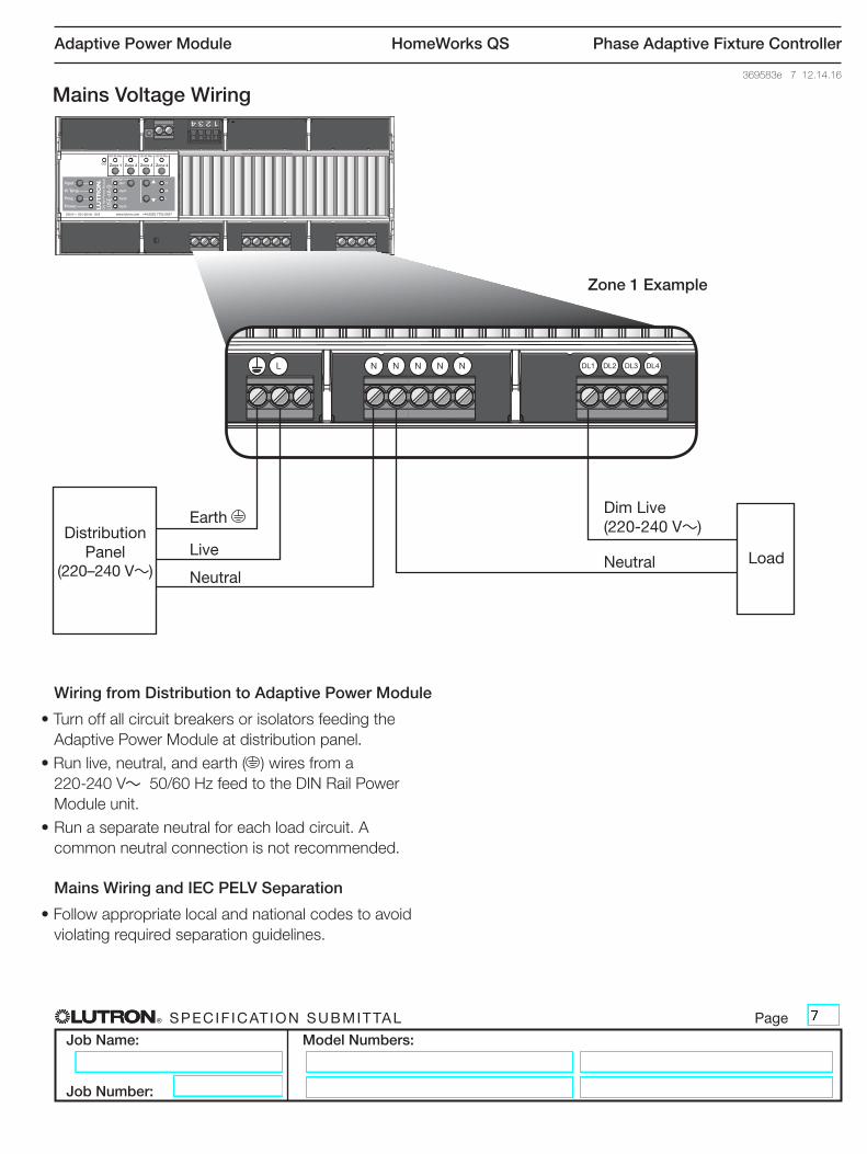
Wiring from Distribution to Adaptive Power Module
•TurnoffallcircuitbreakersorisolatorsfeedingtheAdaptive Power Module at distribution panel.
•Runlive,neutral,andearth( ) wires from a 220-240 V~50/60HzfeedtotheDINRailPowerModule unit.
•Runaseparateneutralforeachloadcircuit.A common neutral connection is not recommended.
Mains Wiring and IEC PELV Separation
•Followappropriatelocalandnationalcodestoavoidviolatingrequiredseparationguidelines.
Dim Live (220-240 V~)
Neutral
H
M
L
LQSE-4A-D
DIN
Rai
l Pow
er M
odul
e
230 V~ 50 / 60 Hz 10 A www.lutron.com +44.(0)20.7702.0657
CCI
500 W Max 800 W Max 500 W Max 500 W Max
Zone 2Zone 1 Zone 3 Zone 4
Input
Hi Temp
Prog
Power
Opt1
Opt2
Opt3
DefOption
Zone 1 Example
Mains Voltage Wiring
H
M
L
LQSE-4A-D
DIN
Rai
l Pow
er M
odul
e
230 V~ 50 / 60 Hz 10 A www.lutron.com +44.(0)20.7702.0657
CCI
500 W Max 800 W Max 500 W Max 500 W Max
Zone 2Zone 1 Zone 3 Zone 4
Input
Hi Temp
Prog
Power
Opt1
Opt2
Opt3
DefOption
L N N N N N DL1 DL2 DL3 DL4
Load
Earth
Neutral
LiveDistribution
Panel(220–240 V~)

® Specif icat ion Submittal page
Job Name:
Job Number:
Model Numbers:
Adaptive Power Module HomeWorks QS Phase Adaptive Fixture Controller
369583e 8 12.14.16
IEC PELV Emergency Contact Closure Input
•ContactClosureInput(CCI)wiringis IECPELV/NEC®Class2. Followallapplicablenationalandlocalcodesforproper circuit separation and protection.
•Turnoffallbreakersorisolatorsfeedingthe Energi Savr Node QS unit at distribution panel be-fore servicing unit.
•TheCCIisalocalcontrolonlyandcannotcontrolother Energi Savr Node QS units over the QS link. Amaximumof32EnergiSavrNodeQSunitsmaybe connected in parallel to an Emergency or Manual override device if the event is intended to affect multiple devices.
•Wheninemergencymode,allzoneoutputswillbeat their programmed emergency light level (configurableforeachzone,defaultis100%). All sensors and controls are locked out.
•Emergencycontactclosureinputisnormallyclosed(NC).TheEnergiSavrNode QS unit is shipped with ajumperpre-installed.
Note: The Energi Savr Node QS unit will default to EmergencyModeiftheCCIisleftopen.IfnoEmergencyContactClosureInputisrequired,pleaseleavethewirejumperintheCCIterminals.
H
M
L
LQSE-4A-D
DIN
Rai
l Pow
er M
odul
e
230 V~ 50 / 60 Hz 10 A www.lutron.com +44.(0)20.7702.0657
CCI
500 W Max 800 W Max 500 W Max 500 W Max
Zone 2Zone 1 Zone 3 Zone 4
Input
Hi Temp
Prog
Power
Opt1
Opt2
Opt3
DefOption
H
M
L
QSNE
-4A-D
DIN
Rai
l Pow
er M
odul
e
230 V~ 50 / 60 Hz 10 A www.lutron.com +44.(0)20.7702.0657
InputS1 S2 S3 S4 CCI
SwitchOccPhotoIR
Type
500 W Max 800 W Max 500 W Max 500 W Max
Zone 2Zone 1 Zone 3 Zone 4
Input
Hi Temp
Prog
Power
Opt1
Opt2
Opt3
DefOption
H
M
L
QSNE
-4A-D
DIN
Rai
l Pow
er M
odul
e
230 V~ 50 / 60 Hz 10 A www.lutron.com +44.(0)20.7702.0657
InputS1 S2 S3 S4 CCI
SwitchOccPhotoIR
Type
500 W Max 800 W Max 500 W Max 500 W Max
Zone 2Zone 1 Zone 3 Zone 4
Input
Hi Temp
Prog
Power
Opt1
Opt2
Opt3
DefOption
CCICommon
Wiring: Emergency Contact Closure Input
CCI COM
Note: Shown with pre-installedjumper.

® Specif icat ion Submittal page
Job Name:
Job Number:
Model Numbers:
Adaptive Power Module HomeWorks QS Phase Adaptive Fixture Controller
369583e 9 12.14.16
Wiring: QS LinkQS Link IEC PELV Wiring
•LinkcommunicatesusingIEC PELV/NECRClass 2wiring.•TurnoffallbreakersorisolatorsfeedingtheAdaptive
Power Module at distribution panel before servicing unit.•Followallapplicablenationalandlocalcodesforproper
circuit separation and protection.•Wiringmaybedaisychainedort-tapped.•TotallengthofQSlinkmustnotexceed600m.•Forlengthsunder150m,usetwo1,0mm2
conductors for control power (24 V-,COM).•Forlengthsover150m,usetwo4,0mm2 conductors
for control power (24 V-,COM).•Useone,twisted-shieldedpairof1,0mm2 conductors fordatalink(MUX,_).
H
M
L
LQSE-4A-D
DIN
Rai
l Pow
er M
odul
e
230 V~ 50 / 60 Hz 10 A www.lutron.com +44.(0)20.7702.0657
CCI
500 W Max 800 W Max 500 W Max 500 W Max
Zone 2Zone 1 Zone 3 Zone 4
Input
Hi Temp
Prog
Power
Opt1
Opt2
Opt3
DefOption
H
M
L
LQSE-4A-D
DIN
Rai
l Pow
er M
odul
e
230 V~ 50 / 60 Hz 10 A www.lutron.com +44.(0)20.7702.0657
CCI
500 W Max 800 W Max 500 W Max 500 W Max
Zone 2Zone 1 Zone 3 Zone 4
Input
Hi Temp
Prog
Power
Opt1
Opt2
Opt3
DefOption
(1) COM
(2) Do Not Connect Teminal 21
(3) MUX
(4) MUX
seeTouch QSwallstations
seeTouch QSwallstations
QSE-CI-DMX
QSE-CI-DMX
Daisy-Chain Wiring Example
T-Tap Wiring Example
1 UnitdoesnotconsumeorsupplyPDUson the QS link. Do not connect the 24 V- wire to unit. Note: 24 V- wire must bypass the unit if other devices on the link consume PDUs.
)Lutron,Lutron,HomeWorks,RTISSEquipped,GRAFIKEye,seeTouch,andQuantumareregistered trademarks of Lutron Electronics Co.,Inc.registeredintheU.S.andothercountries.
RTISS-TE,EnergiSavrNodearetrademarksofLutronElectronicsCo.,Inc.