adaptive deb locking filter
TRANSCRIPT

8/8/2019 Adaptive Deb Locking Filter
http://slidepdf.com/reader/full/adaptive-deb-locking-filter 1/6
614 IEEE TRANSACTIONS ON CIRCUITS AND SYSTEMS FOR VIDEO TECHNOLOGY, VOL. 13, NO. 7, JULY 2003
Adaptive Deblocking FilterPeter List, Anthony Joch, Jani Lainema, Gisle Bjøntegaard, and Marta Karczewicz
Abstract—This paper describes the adaptive deblocking filter
used in the H.264/MPEG-4 AVC video coding standard. Thefilter performs simple operations to detect and analyze artifactson coded block boundaries and attenuates those by applying aselected filter.
Index Terms—Block-based coding, video coding, video filtering,video signal processing.
I. INTRODUCTION
THERE are two building blocks within the architecture of
the H.264/MPEG-4 AVC video coding standard [1] which
can be a source of blocking artifacts. The most significant one
is the block-based integer discrete cosine transforms (DCTs) in
intra and inter frame prediction error coding. Coarse quantiza-tion of the transform coefficients can cause visually disturbing
discontinuities at the block boundaries [2]–[4]. The second
source of blocking artifacts is motion compensated prediction.
Motion compensated blocks are generated by copying interpo-
lated pixel data from different locations of possibly different
reference frames. Since there is almost never a perfect fit for
this data, discontinuities on the edges of the copied blocks
of data typically arise. Additionally, in the copying process,
existing edge discontinuities in reference frames are carried
into the interior of the block to be compensated. Although the
small 4 4 sample transform size used in H.264/MPEG-4 AVC
somewhat reduces the problem, a deblocking filter is still an
advantageous tool to maximize coding performance.There are two main approaches in integrating deblocking fil-
ters into video codecs. Deblocking filters can be used either as
post filters or loop filters. Post filters only operate on the dis-
play buffer outside of the coding loop, and thus are not norma-
tive in the standardization process. Because their use is optional,
post-filters offer maximum freedom for decoder implementa-
tions. On the contrary, loop filters operate within the coding
loop. That is, the filtered frames are used as reference frames for
motion compensation of subsequent coded frames. This forces
all standard conformant decoders to perform identical filtering
in order to stay in synchronization with the encoder. Naturally,
a decoder can still perform post filtering in addition to the loop
filtering if found necessary in a specific application.
Manuscript received May 2, 2003.P. List is with Deutsche Telekom, T-Systems, 64295 Darmstadt, Germany
(e-mail: [email protected]).A. Joch is with UB Video Inc., Vancouver, BC V6B 2R9, Canada (e-mail:
[email protected]).J. Lainema and M. Karczewicz are with the Nokia Research Center,
Irving, TX 75039 USA (e-mail: [email protected]; [email protected]).
G. Bjøntegaard is with TANDBERG, N-1324 Lysaker, Norway (e-mail:[email protected]).
Digital Object Identifier 10.1109/TCSVT.2003.815175
Performing the filtering inside the coding loop has several
advantages over post filtering. Firstly, the requirement of a loopfilter guarantees a certain level of quality. This is especially im-
portant in modern communications systems where decoders of
several manufacturers are used to decode distributed video ma-
terial. With a loop filter in the codec design, content providers
can safely assume that their material is processed by proper de-
blocking filters, guaranteeing the quality level expected by the
producer.
Secondly, there is no need for an extra frame buffer in the
decoder. In the post-filtering approach, the frame is typically
decoded into a reference frame buffer. An additional frame
buffer may be needed to store the filtered frame to be passed to
the display device. In the loop-filtering approach, however, fil-
tering can be carried out macroblock-wise during the decoding
process, and the filtered output stored directly to the reference
frame buffers.
Thirdly, empirical tests have shown that loop filtering typi-
cally improves both objective and subjective quality of video
streams with significant reduction in decoder complexity com-
pared to post filtering [3], [5]. Quality improvements are mainly
due to the fact that filtered reference frames offer higher quality
prediction for motion compensation. Reductions in computa-
tionalcomplexitycan be achieved by takinginto account thefact
that the image area in past frames is already filtered, and thereby
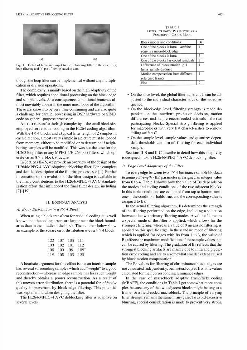
optimizing the filtering process accordingly. Fig. 1 shows the re-
constructed frame in a loop-filter (left) and a post-filter (right)based TML 8.51 system before loop/post filtering. It can be seen
that the main coding artifact in the loop-filter case is the block-
iness on the 4 4 grid caused by prediction error coding. This
artifact can be efficiently compensated by the deblocking filter
described in this paper. In the post-filter case, the blockinessdoes not followthe grid boundaries but is spread inside the 4 4
blocks due to blocky reference images that were used for mo-
tion compensation [4]. This additionally results in an increased
amount of residual coding to remove artificially created high
frequency edges and possible ringing effects at low bit rates.
Despite all of these advantages, the requirement of a norma-
tive loop filter was extensively debated during the development
of the H.264/MPEG-4 AVC standard. A critical factor in thedebate was the comparatively high complexity of the loop filter.
Even after a tremendous effort in speed optimization of the fil-
tering algorithms, the filter can easily account for one-third of
the computational complexity of a decoder. This is true even
1While this paper describes the deblocking filter design in the final draft of the H.264/MPEG-4 AVC standard [1], results and figures have been generatedusing the TML 8.5 software, which corresponds to an earlier draft specification[6]. Some parts of the deblocking filter design have been modifiedin the interimbetween these drafts (primarily for complexity reduction). However, the majorproperties and the performance of the filter have remained unchanged.
1051-8215/03$17.00 © 2003 IEEE
8/8/2019 Adaptive Deb Locking Filter
http://slidepdf.com/reader/full/adaptive-deb-locking-filter 2/6
LIST et al.: ADAPTIVE DEBLOCKING FILTER 615
(a) (b)
Fig. 1. Detail of luminance input to the deblocking filter in the case of (a)loop-filtering and (b) post-filtering based system.
though the loop filter can be implemented without any multipli-
cation or division operations.
The complexity is mainly based on the high adaptivity of the
filter, which requires conditional processing on the block edge
and sample levels. As a consequence, conditional branches al-
most inevitably appear in the inner most loops of the algorithm.
These are known to be very time consuming and are also quite
a challenge for parallel processing in DSP hardware or SIMD
code on general-purpose processors.
Another reason for the high complexity is the small block sizeemployed for residual coding in the H.264 coding algorithm.
With the 4 4 blocks and a typical filter length of 2 samples in
each direction, almost every sample in a picture must be loaded
from memory, either to be modified or to determine if neigh-
boring samples will be modified. This was not the case for the
H.263 loop filter or any MPEG-4/H.263 post filters, which op-
erate on an 8 8 block structure.
In Sections II–IV, we provide an overview of the design of the
H.264/MPEG-4 AVC adaptive deblocking filter. For a complete
and detailed description of the filtering process, see [1]. Further
information on the evolution of the filter design is available in
the many contributions to the H.264/MPEG-4 AVC standard-
ization effort that influenced the final filter design, including
[7]–[19].
II. BOUNDARY ANALYSIS
A. Error Distribution in a 4 4 Block
When using a block transform for residual coding, it is well
known that the coding errors are larger near the block bound-
aries than in the middle of the block. The numbers below show
an example of the square error distribution over a 4 4 block
A heuristic argument for this effect is that an interior sample
has several surrounding samples which add “weight” to a good
reconstruction—whereas an edge sample has less such weight
and thereby obtains a poorer reconstruction. As a result of
this uneven error distribution, there is a potential for objective
quality improvement by block edge filtering. This potential
was kept in mind when designing the filter.
The H.264/MPEG-4 AVC deblocking filter is adaptive on
several levels.
TABLE IFILTER STRENGTH PARAMETER AS A
FUNCTION OF CODING MODE
• On the slice level, the global filtering strength can be ad-
justed to the individual characteristics of the video se-
quence.
• On the block-edge level, filtering strength is made de-
pendent on the inter/intra prediction decision, motion
differences, and the presence of coded residuals in the two
participating blocks. Special strong filtering is appliedfor macroblocks with very flat characteristics to remove
“tiling artifacts”.
• On the sample level, sample values and quantizer-depen-
dent thresholds can turn off filtering for each individual
sample.
Sections II-B and II-C describe in detail how this adaptivity
is designed into the H.264/MPEG-4 AVC deblocking filter.
B. Edge Level Adaptivity of the Filter
To every edge between two 4 4 luminance sample blocks, a
Boundary-Strength (Bs) parameter is assigned an integer value
from 0 to 4. Table I shows how the value of Bs depends onthe modes and coding conditions of the two adjacent blocks.
In this table, conditions are evaluated from top to bottom, until
one of the conditions holds true, and the corresponding value is
assigned to Bs.
In the actual filtering algorithm, Bs determines the strength
of the filtering performed on the edge, including a selection
between the two primary filtering modes. A value of 4 means
a special mode of the filter is applied, which allows for the
strongest filtering, whereas a value of 0 means no filtering is
applied on this specific edge. In the standard mode of filtering
which is applied for edges with Bs from 1 to 3, the value of
Bs affects the maximum modification of the sample values that
can be caused by filtering. The gradation of Bs reflects that thestrongest blocking artifacts are mainly due to intra and predic-
tion error coding and are to a somewhat smaller extent caused
by block motion compensation.
The Bs values for filtering of chrominance block edges are
not calculated independently, but instead copied from the values
calculated for their corresponding luminance edges.
In the case of macroblock adaptive frame/field coding
(MBAFF), the conditions in Table I get somewhat more com-
plex because any of the two adjacent blocks might belong to a
frame- or a field-coded macroblock. The principle of varying
filter strength remains the same in any case. To avoid excessive
blurring, special consideration is made to prevent very strong

8/8/2019 Adaptive Deb Locking Filter
http://slidepdf.com/reader/full/adaptive-deb-locking-filter 3/6
616 IEEE TRANSACTIONS ON CIRCUITS AND SYSTEMS FOR VIDEO TECHNOLOGY, VOL. 13, NO. 7, JULY 2003
Fig. 2. One-dimensional visualization of a block edge in a typical situationwhere the filter would be turned on.
filtering of horizontal edges of field-coded macroblocks, since
the spatial extent of the vertical filtering is doubled for such
macroblocks.
C. Sample-Level Adaptivity of the Filter
In deblocking filtering, it is crucially important to be able to
distinguish between true edges in the image and those created by
quantization of the DCT coefficients. To preserve image sharp-ness, the true edges should be left unfiltered as much as possible
while filtering artificial edges to reduce their visibility.
In order to separate these two cases, the sample values across
every edge to be filtered are analyzed. Let us denote one line of
samplevalues insidetwo neighboring4 4 blocks by , , ,
, , , , , with the actual boundary between and ,
as shown in Fig. 2. Up to three sample values for luminance and
one for chrominance on each side of the edge may be modified
by the filtering process.
As stated in Section II-B, filtering does not take place for
edges with Bs equal to zero. For edges with nonzero Bs values, a
pair of quantization-dependent parameters, referred to as and
, are used in the content activity check that determines whether
each set of samples is filtered. Filtering on a line of samples only
takes place if the three conditions
(1)
(2)
(3)
all hold. In these conditions, both table-derived thresholds and
are dependant on the average quantization parameter (QP) em-
ployed over the edge, as well as encoder selected offset values
that can be used to control the properties of the deblocking filter
on the slice level. These table index values are calculated as(4)
(5)
where 0–51 represents the range of valid QP values.
The values of and are defined approximately according
to the following relationships:
(6)
(7)
Thus, in general, is considerably smaller than . To
define the actual tables, variations from this basic relationship
have been made based on empirical tests to produce visually
pleasing results for a variety of content. In particular, at the low
end of the table, values are clipped to zero so that for values of
or , one or both of and become
0 and filtering is effectively turned off.
The dependency of and on QP links the strength of fil-
tering to the general quality of the reconstructed picture prior to
filtering. Since the thresholds values increase with QP, bound-aries that contain higher content activity are filtered when QP
is larger, since the coding error (size of artifacts) increases with
QP. The exponential nature of reflects the dependency on QP
of the size of an expected blocking artifact, since the quantiza-
tion step size doubles every time QP is increased by 6.
D. Slice-Level Adaptivity of the Filter
On the slice level, encoder-selectable offsets—referred to as
and —may be u sed t o a djust t he v alues o f and
used in filtering and thereby increase or decrease the amount
of filtering that takes place compared to filtering with the default
zero offsets. The offset values are transmitted in the slice header
syntax and are applied to the QP-based addressing of the and
tables.
The ability to control the properties of deblocking filter by
transmitting nonzero offsets provides the encoder designer with
the ability to optimize the subjective quality of the decoded
video beyond that provided by use of the default tables. For
example, reducing the amount of filtering by transmitting neg-
ative offsets can help to maintain the sharpness of small spa-
tial details, particularly with high-resolution video content, in
which small blocking artifacts tend to be less apparent. On the
other hand, using positive offsets to increase the amount of fil-
tering can improve subjective quality on content where visible
blocking artifacts remain if the default values are used. This isbeneficial for lower resolution content with smooth brightness
transitions and to remove additional artifacts that might be in-
troduced by sub-optimal motion estimation, mode decisions, or
residual coding.
III. FILTERING
A. Overview of Filtering Operations
In order to ensure a perfect match in the filtering process
between encoders and decoders, filtering operations must be
conducted in a specific order throughout each coded picture.
Filtering is conducted “in-place,” so that the modified sample
values after featuring each line of samples across an edge areused as input values to subsequent operations.
Filtering occurs on a macroblock basis, with horizontal fil-
tering of the vertical edges performed first, followed by vertical
filtering (of the horizontal edges). Both directions of filtering
on each macroblock must be conducted before moving on to the
next macroblock. The macroblocks are filtered in raster-scan
order throughout the picture. For MBAFF coded frames, in
which pairs of vertically adjacent macroblocks are grouped
together, the filtering order is based on these macroblock pairs,
with the pairs being filtered in raster-scan order throughout the
frame, and the top macroblocks being filtered first within each
pair.

8/8/2019 Adaptive Deb Locking Filter
http://slidepdf.com/reader/full/adaptive-deb-locking-filter 4/6
8/8/2019 Adaptive Deb Locking Filter
http://slidepdf.com/reader/full/adaptive-deb-locking-filter 5/6
618 IEEE TRANSACTIONS ON CIRCUITS AND SYSTEMS FOR VIDEO TECHNOLOGY, VOL. 13, NO. 7, JULY 2003
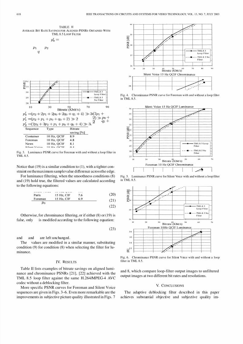
TABLE IIAVERAGE BIT RATE SAVINGS FOR ALIGNED PSNRS OBTAINED WITH
TML 8.5 LOOP FILTER
Fig. 3. Luminance PSNR curve for Foreman with and without a loop filter inTML 8.5.
Notice that (19) is a similar condition to (1), with a tighter con-
straint on themaximum samplevalue difference acrossthe edge.
For luminance filtering, when the smoothness conditions (8)
and (19) hold true, the filtered values are calculated accordingto the following equations:
(20)
(21)
(22)
Otherwise, for chrominance filtering, or if either (8) or (19) is
false, only is modified according to the following equation:
(23)
and and are left unchanged.
The values are modified in a similar manner, substitutingcondition (9) for condition (8) when selecting the filter for lu-
minance.
IV. RESULTS
Table II lists examples of bitrate savings on aligned lumi-
nance and chrominance PSNRs [21], [22] achieved with the
TML 8.5 loop filter against the same H.264/MPEG-4 AVC
codec without a deblocking filter.
More specific PSNR curves for Foreman and Silent Voice
sequences are given in Figs. 3–6. Even more remarkable are the
improvements in subjective picture quality illustrated in Figs. 7
Fig. 4. Chrominance PSNR curve for Foreman with and without a loop filterin TML 8.5.
Fig. 5. Luminance PSNR curve for Silent Voice with and without a loop filter
in TML 8.5.
Fig. 6. Chrominance PSNR curve for Silent Voice with and without a loopfilter in TML 8.5.
and 8, which compare loop-filter output images to unfiltered
output images at two different bit rates and resolutions.
V. CONCLUSIONS
The adaptive deblocking filter described in this paper
achieves substantial objective and subjective quality im-

8/8/2019 Adaptive Deb Locking Filter
http://slidepdf.com/reader/full/adaptive-deb-locking-filter 6/6
LIST et al.: ADAPTIVE DEBLOCKING FILTER 619
(a) (b)
Fig.7. Detail oftheluminance outputin the caseof (a) loopfiltering and (b) nofiltering. CIF sequence was coded at 200 kbps and 15 fps.
(a) (b)
Fig.8. Detail oftheluminance outputin the caseof (a) loopfiltering and (b) nofiltering. QCIF sequence was coded at 30 kbps and 10 fps.
provements with a reasonably simple algorithm. The good
performance is based on reliable detection of real and artifi-
cially created edges and efficient filtering of the latter ones.
Bit-rate savings exceeding 9% are observed with equal PSNR
levels together with significantly improved visual quality.
REFERENCES
[1] Draft ITU-T Recommendation and Final Draft International Standard of JointVideo Specification (ITU-T Rec. H.264/ISO/IEC 14 496-10 AVC),Mar. 2003.
[2] K. K. Pang and T. K. Tan, “Optimum loop filter in hybrid coders,” IEEE Trans. Circuits Syst. Video Technol., vol. 4, pp. 158–167, Apr. 1994.
[3] Y.-L. Lee and H. W. Park, “Loop filtering and post-filtering for low-bit-rates moving picture coding,” Signal Processing: Image Commun., vol.16, pp. 871–890, 2001.
[4] S. D. Kim, J. Yi, H. M. Kim, and J. B. Ra, “A deblocking filter withtwo separate modes in block-based video coding,” IEEE Trans. CircuitsSyst. Video Technol., vol. 9, pp. 156–160, Feb. 1999.
[5] J. Lainema andM. Karczewicz, “TML 8.4Loop FilterAnalysis,” ITU-TSG16 Doc. VCEG-N29, 2001.
[6] (2001) H.26L Test Model Long Term Number 8 (TML-8). [Online].Available: ftp://standard.pictel.com/video-site/h26L/
[7] J.Lainema andM. Karczewicz, “Core Experiment Results onLow Com-plexity Loop Filtering,” ITU-T SG16 Doc. VCEG-M21, 2001.
[8] , “Further Improvements on TML Loop Filtering,” ITU-T SG16Doc. VCEG-M22, 2001.
[9] G. Bjøntegaard and I. Lille-Langoy, “Possible Simplifications of the
Present Deblocking Filter in TML 5.9,” ITU-T SG16 Doc. VCEG-M30,2001.
[10] P. List, “Proposal for a Simplification of the H.26L Loopfilter,” ITU-TSG16 Doc. VCEG-M48, 2001.
[11] , “Report of the Ad Hoc Committee on Loop Filter Improvement,”ITU-T SG16 Doc. VCEG-N08r1, 2001.
[12] S. Sun and S. Lei, “Improved TML Loop Filter With Lower Com-plexity,” ITU-T SG16 Doc. VCEG-N17, 2001.
[13] G. Côté, L. Winger, and M. Gallant, “Lower Complexity DeblockingFilter With In-Place Filtering,” Doc. VCEG-O39, 2001.
[14] P. List, “AHG Report: Loop Filter,” Doc. JVT-B011r2, 2002.[15] J. Au, B. Lin, A. Joch, and F. Kossentini, “Complexity Reduction and
Analysis for Deblocking Filter,” Doc. JVT-C094, 2002.[16] A. Joch, “Improved Loop-Filter Tables and Variable-Shift Table In-
dexing,” Doc. JVT-D038, 2002.[17] , “Loop Filter Simplification and Improvement,” Doc. JVT-D037,
2002.
[18] C. Gomila and A. Joch, “Simplified Chroma Deblocking (Revisited),”Doc. JVT-E089, 2002.
[19] A. MacInnis and S. Zhong, “Corrections to Loop Filter in the Case of MB-AFF,” Doc. JVT-F027, 2002.
[20] A. K. Jain, Fundamentals of Digital Image Processing. New York:Prentice-Hall, 1989.
[21] G. Bjøntegaard, “Calculation of Average PSNR Differences BetweenRD-Curves,” ITU-T SG16 Doc. VCEG-M33, 2001.
[22] , “Recommended Simulation Conditions for H.26L,” ITU-T SG16
Doc. VCEG-M75, 2001.
Peter List was born in 1957. He graduated inphysics in 1985 and received the Ph.D. degree inapplied physics in 1989, both from the University of Frankfurt/Main, Germany.
He is project manager at T-Systems Nova,Darmstadt, Germany, a reserach and developmentcompany of Deutsche Telekom. Since 1990, hehas been with Deutsche Telekom, and has activelyfollowed the international standardization of videocompression in ISO, ITU, and several Europeanprojects for more than ten years.
Anthony Joch received the B.Eng. degree incomputer engineering from McMaster University,Hamilton, ON, Canada, in 1999, and the M.A.Sc.degree in electrical engineering from the Universityof British Columbia, Vancouver, BC, Canada, in2002.
In 2000, he joined UB Video Inc., Vancouver,BC, where he is currently a Senior Engineerinvolved in the development of software codecs forthe H.264/MPEG-4 AVC standard. His researchinterests include reduced-complexity algorithms for
video encoding, video pre- and post-processing, and multimedia systems. Hehas been an active contributor to the H.264/MPEG-4 AVC standardizationeffort, particularly in the area of deblocking filtering and as a co-chair of thead-hoc group for bitstream exchange.
Jani Lainema received the M.Sc. degree in computer engineering from Tam-pere University of Technology, Tampere, Finland, in 1996.
He joined the Visual Communications Laboratory of Nokia Research Center,Irving, TX, in 1996, where he is currently a Project Manager and Senior Re-search Scientist. His research interests include video, imageand graphics codingand communications.
Gisle Bjøntegaard received the Dr. Phil.degree in physics from the Universityof Oslo, Oslo, Norway, in 1974.
From 1974 to 1996, he was a Senior Scientist with Telenor Research andDevelopment, Oslo, Norway. His areas of research included radio link network design, reflector antenna design and construction, digital signal procession,and development of video compression methods. From 1996 to 2002, he wasa Group Manager at Telenor Broadband Services, Oslo, Norway, where his
areas of work included the design of point-to-point satellite communicationand development of satellite digital TV platform. Since 2002, he has beena Principal Scientist at Tandberg Telecom, Lysaker, Norway, working withvideo-coding development and implementation. He has contributed actively tothe development of the ITU video standards H.261, H.262, H.263, and H.264,as well as to ISO/IEC MPEG2 and MPEG4.
Marta Karczewicz received the M.S. degree in electrical engineering in 1994and Dr. Technol. degree in 1997, both from Tampere University of Technology,Tampere, Finland.
During 1994–1996, she was Researcher in the Signal Processing Laboratory,Tampere University of Technology. Since 1996, she has been with the VisualCommunication Laboratory, Nokia Research Center, Iriving, TX, where she iscurrentlya Senior Research Manager. Her research interests include imagecom-pression, communication and computer graphics.