adaptive composite structures in shape...
TRANSCRIPT

ADAPTIVE COMPOSITE STRUCTURES IN SHAPE CONTROL APPLICATIONS Merja Sippola, Tomi Lindroos Journal of Structural Mechanics, Timo Brander Vol. 40, No. 1, 2007, pp. 65-79 SUMMARY This paper presents the development of a smart or adaptive structure using the ongoing adaptive airfoil development work of VTT, TKK and University of Oulu as a demonstrative example. The development of a smart structure is a multi-field task that needs expertise from the fields of materials and materials integration, actuators and sensors, structural mechanics, modeling, manufacture, control and testing. This paper presents the basics of the structure, actuation, sensing and control of the adaptive composite airfoil and the current state of the development work as well as some further development plans. INTRODUCTION Lightweight and effectively load bearing shell structure is a common structural element in many vehicles, machines and devices. Fiber Reinforced Plastic (FRP) composite and sandwich structures are particularly interesting from the viewpoint of smart structures, because their mechanical properties are relatively easy to tailor (fiber orientation, stacking of fiber layers, asymmetry etc.). Moreover, their manufacturing technology is such that it is possible to embed functional materials based actuators and sensors and control systems into the structure. In smart (active, adaptive) structures, Shape Memory Alloys can be used to generate motions or forces. SMA actuators are thermomechanical devices that convert heat energy into mechanical work [1]. The most commonly used SMA actuators are NiTi wires. Stress above a certain threshold value elongates wire. This pseudoplastic elongation happens by orientation of the martensitic variants. If the loading is removed the orientation remains until the material is heated. Electric current is typically used to heat the material. Heat energy causes a solid-solid phase transformation from martensite to austenite, which leads to strain recovery [2]. SMA elements are able to recover large inelastic strain, reliably carry out mechanical work upon heating or work as thermally driven actuators due to the coupling between stress and temperature. However, the SMA responses under thermomechanical loads, even if reversible and reproducible, are nonlinear, hysteretic and path dependent.
65

In cyclic (stress, temperature) loading the same value of the macroscopic strain may be realized at a broad range of applied stress and temperature conditions. The hysteresis originates from differences in free energy of the different phases – the reversal of the transformation occurs via different route. Due to the complexity of the thermomechanical behaviour of SMAs the modelling of SMA actuators and SMA actuated active structures is a challenging task. First experiments of SMA based composites were made at the end of 1980’s at Virginia Tech by Rogers and Robertshaw [3]. After that hybrid composites based on SMAs have been a subject of active investigation. Shape memory materials have been integrated within monolithic or composite materials to produce components whose functionality or static and dynamic properties can be enhanced or actively tuned in response to environ-mental changes. Partly due to the technical simplicity of the manufacturing process most of the efforts with embedded shape memory actuators have been directed to polymer matrix composites [4,5]. Shape memory composites can be manufactured with conventional FRP composite fabrication methods. Many modifications about the basic manufacturing processes have been presented [6,7,8]. Polymer composites with embedded shape memory materials have been demonstrated in shape and position control; buckling control; active, passive and semiactive control of vibration and acoustic transmission as well as in creep resistant materials subjected to dynamic loads and impact damage resistant structures. A crucial part of a smart structure is the control system. Usually the target is either shape control or vibration control of the structure. (Note: In an active shape control system suppression of the natural vibrations caused by the actuation itself is an important subtask.) Stiffness control can be used to control the vibration of a dynami-cally loaded structure in a semi-active way by avoiding resonance. Sometimes the target is to increase the buckling strength of the structure. Shape control of active structures has been studied for example in [9], active vibration control of structures in [10] and stiffness control in [11]. [12] is an example of buckling control of a simple SMA-FRP structure. In an active airfoil the aim is to control the shape of the airfoil to control the drag and lift properties [13,14]. This can then be used for many things: In a transonic aeroplane shape control can be used to reduce drag and thus to reduce fuel consumption [15]. In wind turbines the most promising concept is reduction of the fatigue loads, which can be used to increase the life of the structure or to enable use of the turbine at higher wind speeds and gusty winds, which would increase the power production [16]. Figure 1 shows a typical mechatronic system [14]. In systems, where the determination of the output from the input is easy, for example a motor that operates at a pre-determined frequency and an accurate model of the motor dynamics is available, the system can be controlled in an open loop (feedforward control, see Figure 2a). In more complicated systems and/or when a reliable model of the system behaviour is not available, closed loop control is necessary (feedback control, see Figure 2b). In smart structures a potential way of controlling the system could be a model based primary controller added with a feedback secondary controller.
66

Figure 1. The components of a mechatronic system [14]
The primary controller need not be very accurate, but in many applications it has to be fast. Large time delay causes sever problems in almost any control system. Time Delay Control (TDC) [17] is one potential solution to this problem.
Figure 2. a) feedforward control b) feedback control [18] Designing the control hardware is an important part of the control designers work. In lightweight rotating systems like a wind turbine blade the control systems has to be robust, small and lightweight and need as little maintenance as possible. There are special small, lightweight components like PC100 and microcontrollers available. Wireless communication would be preferable. These are subjects for further develop-ment work. In the demonstrations the hardware issues have been in a smaller role. MOTIVATION FOR THE ADAPTIVE AIRFOIL WORK There is an interest of doubling or quadrupling the rated power of wind turbines from the present maximum of about 5 MW, especially for offshore applications. This increases the blade length to about 80 or 100 m. The growth in size of blades is not feasible using the present technologies and materials. Also the slenderness of wind turbines has increased leading to increased importance of vibration and fatigue control of blades and supporting structures. These increasing requirements call for new
67
structural concepts and advanced materials and also for more adaptive solutions. Better control of the turbine, such as advanced blade pitch control, advanced generator control, airfoil shape control or their combination, has to be developed and utilized. THERMOMECHANICS OF EMBEDDED SMA WIRES The main results of a literature study and discussions with metallurgists specialised on SMAs on the complex thermomechanical behaviour of SMAs as well as the basics of design with SMA actuators are reported in another paper of this issue of Structural Mechanics (in Finnish). Structural tuning, modal modification or vibration and acoustic control can be ac-complished through 1) actively changing the stiffness of the embedded SMA elements or 2) activating pre-strained SMA elements in order to generate a stress that will modify the vibration response of the whole composite structure. The two techniques are called Active Property Tuning (APT) and Active Strain Energy Tuning (ASET) [19]. Dynamic response tuning of composite structures with embedded SMAs has been studied by several authors. Turner [20] showed that the natural frequency of a composite beam with embedded SMA wires can be increased remarkably by activating the SMAs. This large effect is due to a so called guitar string effect. To reach this effect the ends of the beam must be fixed. Unfortunately such a structure is not very practical. K. Lau [21] presented the effect of APT and ASET on natural frequency of a composite beam. The conclusion was that APT has only slight effect on natural frequency, but enhances damping. One must note that even though SMAs have a large hysteresis, damping achieved by SMAs embedded into epoxy matrix laminates is usually lower than damping achieved by use of special high-damping polymer matrices only. Also the effects of temperature on the stiffness of the matrix must be taken into account [22]. On the other hand the natural frequency of a load carrying composite beam can be controlled using external wires [11]. This kind of semiactive damping by avoiding frequencies close to resonance has a great potential in lightweight structures. Jonnalagadda et al [23] studied the strains in a SMA wire embedded into composite matrix in situ with the Moire method. They found that embedded even in this rather flexible matrix, the transformation in the SMA occurred only near the ends of the beam, in the middle part of the beam the transformation vanished. This rather surprising result is partially explainable by the fact that the epoxy used had low glass transition temperature. Thus the temperature in these tests was not lifted to the nominal Austenite Finish temperature Af. Still, more transformation throughout the beam was expected. The studies of SMA based functional composites have revealed the lack of basic know-ledge in understanding the SMA material behaviour. Especially the issues concerning the generation of recovery stresses of embedded SMA wires are very important. Desig-ning and manufacturing of complicated structures requires knowledge about the thermo-mechanical behaviour of the adaptive composites. Despite of that only a few studies have been presented. Tsoi et al. [24] showed that the prestrain of SMA wires embedded into composite matrix does not have a straight effect on the generation of recovery stresses.
68

These results can be explained by studying the interaction of the SMA wires and the surrounding laminate and the thermomechanical behaviour of the SMAs. As the volume fraction of the SMA wires is usually small, the elastic stress in the SMAs grows high even in a moderately stiff laminate. Stalmans et al [25] explained what happens inside the embedded SMAs. Usually in actuator use the SMA has originally been cooled from austenite, resulting in Self Accommodated Martensite (SAM), in which the martensite variants are randomly oriented. In the initial straining (loading to the plateau stress and release of the load) in the martensite phase, part of this SAM has oriented to Preferen-tially Oriented Martensite (POM), resulting in a pseudoplastic strain (elongation of the wire). Then the wires were embedded during the lamination and the laminate was cured. Now, if the stress in the SMA wires during the actuation grows above the plateau stress, several things happen simultaneously: part of the remaining SAM is transforming to austenite, part of the remaining SAM is orienting to POM and part of the POM is transforming to austenite. The orienting of SAM to POM elongates the wire and thus works opposite to the strain recovery. Only the transformation of POM to austenite leads to shortening of the wire i.e. strain recovery and as the transformation of POM is partially constrained by the matrix, the strain recovery is slow. When the stress in the SMA exceeds the plateau stress, it also shifts the phase trans-formation temperatures upwards, which means that the wires need to be heated to higher temperature to get full transformation. In many experiments reported in literature this shift of transformation temperatures has not been taken into account and thus the heating has been inadequate. The explanation to the observation that the restrain of the wires does not have a straight effect on the generation of recovery stresses is that in the embedded SMA only small part of the potential transformation takes place. Increasing the heating gives more transformation, but at a slow rate. If the wires were placed in sleeves before embedding and thus bonded only at their ends, the situation is somewhat different, especially if the laminate can bend. In this case the restriction caused by the matrix on the strain of the SMA wires is not as severe as in complete bonding. If the laminate can bend, this will leave some room for the wires to shorten more than the laminate and the stress in the SMA wires does not increase as much as in the case of perfectly bonded wires. Thus more transformation and thus more strain recovery is achieved and also at a higher rate. If the curvature of the laminate grows large the wires will start pushing towards the walls of the sleeves. This internal transverse loading may break the laminate in cyclic loading. The sleeve method is preferred for shape control if relatively small bending is needed. If the bending needed is large, either the wires should be bonded at intervals throughout the laminate or the laminate around the sleeve should be reinforced for internal trans-verse loads. An important thing which should be taken into account in the design of adaptive structures based on embedded SMA wires is the small cooling rate due to the thermally insulating polymer matrix. Cooling may be enhanced by placing the wires close to the surface of the laminate and using a cooling flow (usually air or water).
69

MODELING SMA laminates and the adaptive airfoil were modelled by ABAQUS FE program both as 3D and shell models [26] using the rebar and rebar shell options of ABAQUS for the SMA wires. The shortening of the SMA wires was modelled by thermal expansion analogy with negative thermal expansion coefficient. Thus the models cannot give absolute displacements nor the correct displacement history but only the relative shape of the deformed structure. The shape obtained with the model corresponded well with the experimentally obtained shape. Adding a SMA material model into the FE models will remove the abovementioned restraints and also give more reliable stress values, as the effects of partial bonding and flexibility of the matrix close to the wires can be modelled. The phenomenological SMA material model of Petr Sittner [27] is being implemented to ABAQUS as UMAT (User programmed MATerial model). The model can reproduce the 1D tensile SMA behaviour with rather good accuracy, while still being physically relatively reliable. Recovery stress generation in embedded SMAs and the consecutive effects on the transformations are included in the model. The original model is intrinsically stress-temperature controlled. Because ABAQUS is a strain controlled program, the model was transformed to strain-temperature controlled form. Preliminary results of this implementation work was reported in [28, in Finnish]. This report also includes a short state-of-art of SMA modeling. MANUFACTURING The manufacturing process of adaptive SMA composites has only a few differences to traditional manufacturing of FRP composites. The most challenging procedure is the embedding of the SMA wires into the structure. Integration of the SMA wires is always some kind of a compromise between maximum force generation and structural integrity. By using large diameter wires it is possible to generate high force volume ratio, but this may increase local stress concentrations and lead to cracking and delamination of the structure. Typical manufacturing process of SMA composites includes an assembly jig where SMA wires are stretched and reinforcement layers are laminated around the SMA wires. On the industrial manufacturing point of view the procedure is quite impractical. Basically two different approaches are used in manufacturing of SMA composites: in the first one the SMA wires are placed inside mechanical sleeves and in the second, more sophisticated, method an adhesive joint is created between the SMA wire and the matrix. The adhesive joint is very critical on the stress levels and temperatures expe-rienced by the SMA wires. In this study a more advanced method to manufacture SMA composites was developed. The method is a combination of mechanical sleeves and adhesive joining. The new method enables use of larger diameter wires because the forces generated by the wires are evenly distributed and pullout of wires is prevented. The manufacturing of an adaptive airfoil comprises of two steps: 1) manufacturing of the insert laminate which includes SMA wires and the desired sensors, 2) manufacturing of the airfoil including the insert laminate. Insert laminates were manufactured in a jig which was designed and manufactured for this purpose. Because high actuation forces
70

are needed to deform the airfoil SMA wires with 0.5 mm diameter were selected as principal actuators. Stress-strain behaviour of the wires is presented in Figure 3.
Figure 3. Stess-strain curves of a SMA wire in martensite (A) and austenite (B) phases The new manufacturing method allows the use of larger diameter wires, which means that the required forces are more easily achievable. In Figure 4 a typical layout of the adaptive composite based on embedded SMA wires is presented.
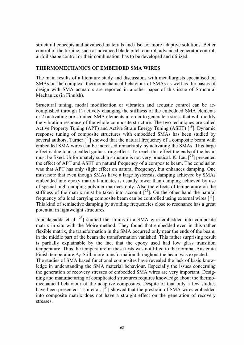
Figure 4. Typical layout of the SMA composite cross section. SMA wire volume fraction ~2% MEASUREMENTS The active structure studied is a glass fiber reinforced plastic airfoil (wind turbine blade section) shown in Figure 5. It is 700 mm long (chord), 100 mm wide and the laminate mean thickness is 3 mm. The SMA actuators are embedded inside the laminates. There are separate actuator wires for the upper and lower skins. The camber of the trailing edge can be adjusted by activation of the actuators. Vertical support seen in Figure 5 is relatively rigid and the shape of the leading edge will not change. The trailing edge of the wing profile bends downwards when the actuators are heated. Cooling returns the original shape of the wing profile. Figure 6 shows the airfoil shape change observed.
A B
71
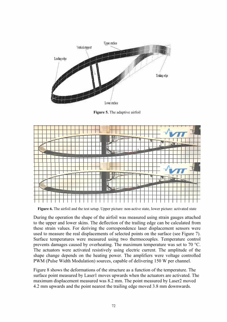
Figure 5. The adaptive airfoil
Figure 6. The airfoil and the test setup. Upper picture: non-active state, lower picture: activated state During the operation the shape of the airfoil was measured using strain gauges attached to the upper and lower skins. The deflection of the trailing edge can be calculated from these strain values. For deriving the correspondence laser displacement sensors were used to measure the real displacements of selected points on the surface (see Figure 7). Surface temperatures were measured using two thermocouples. Temperature control prevents damages caused by overheating. The maximum temperature was set to 70 °C. The actuators were activated resistively using electric current. The amplitude of the shape change depends on the heating power. The amplifiers were voltage controlled PWM (Pulse Width Modulation) sources, capable of delivering 150 W per channel. Figure 8 shows the deformations of the structure as a function of the temperature. The surface point measured by Laser1 moves upwards when the actuators are activated. The maximum displacement measured was 8.2 mm. The point measured by Laser2 moved 4.2 mm upwards and the point nearest the trailing edge moved 3.8 mm downwards.
72
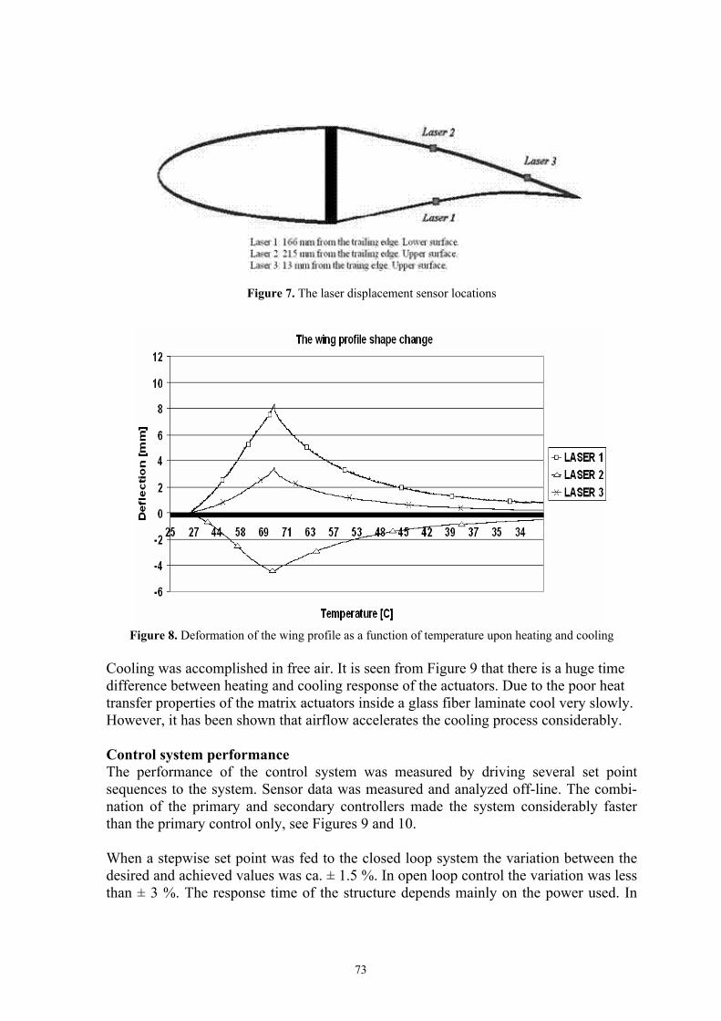
Figure 7. The laser displacement sensor locations
Figure 8. Deformation of the wing profile as a function of temperature upon heating and cooling
Cooling was accomplished in free air. It is seen from Figure 9 that there is a huge time difference between heating and cooling response of the actuators. Due to the poor heat transfer properties of the matrix actuators inside a glass fiber laminate cool very slowly. However, it has been shown that airflow accelerates the cooling process considerably. Control system performance The performance of the control system was measured by driving several set point sequences to the system. Sensor data was measured and analyzed off-line. The combi-nation of the primary and secondary controllers made the system considerably faster than the primary control only, see Figures 9 and 10. When a stepwise set point was fed to the closed loop system the variation between the desired and achieved values was ca. ± 1.5 %. In open loop control the variation was less than ± 3 %. The response time of the structure depends mainly on the power used. In
73

these tests the actuator current flow was limited to 1 A. If the maximum current level is increased, the system will react faster.
Figure 9. Open loop response to staircase type set point
Figure 10. Closed loop response to staircase type set point
CONCLUSIONS An adaptive wing profile was designed, manufactured and tested. New tools for desig-ning and manufacturing of SMA actuated FRP composite structures were developed and demonstrated. The developed control system works accurately enough for the shape control purpose of the airfoil in laboratory conditions. The performance of the system was measured in laboratory conditions. Real loadings were not present in these tests. In a real application the volume fraction of SMA wires should be higher for the actuation to be able to function against external loads (flow) and the control algorithm need to be modified.
74
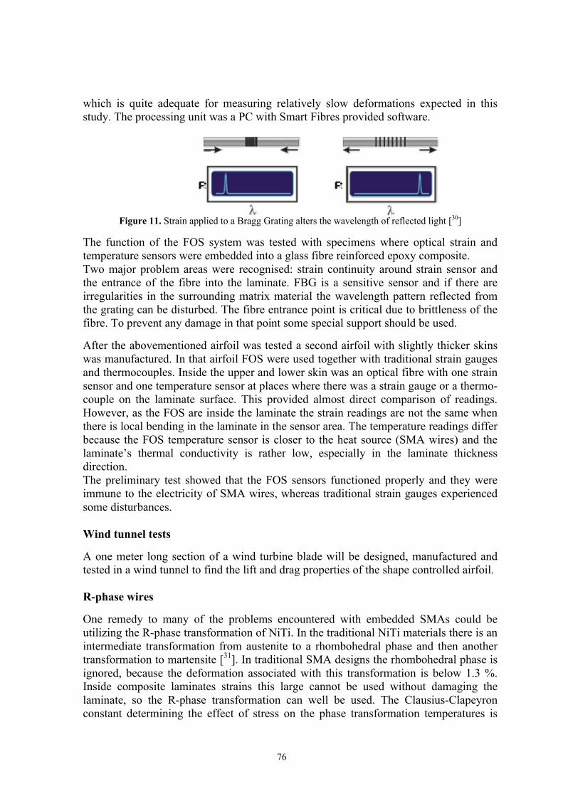
The development of an adaptive structure is an iterative process that requires knowledge from many fields of engineering. An important part of the research work is the development of tools and manufacturing methods that can take the process closer to industrial scale. Especially the modelling tools and the manufacturing processes need further development to make this kind of adaptive structures to be commercially accepted. FURTHER ACTIONS Optical sensors The use of fibre optical sensors (FOS) has been studied at TKK [29]. The goal is to use embedded fibre optical sensors to measure strains and temperatures of the airfoil structure. The use of embedded FOS’s offers certain advantages over traditional electrical strain gauges and thermocouples. Firstly, when the sensors are embedded into the laminate structure the airfoil can be kept clear of any disturbing objects. Secondly, the electricity used to activate the SMA wires tends to disturb the signal of electrical transducers. The optical transducers are inert to external electromagnetic radiation. Based on a literature study Fibre Bragg Grating (FBG) sensors were selected. The sensing system includes a sensor network, an interrogator unit and a processing unit. The current system can measure two channels i.e. two optical fibres, which can include several strain sensors and a temperature sensor. The strain sensing capacity of each channel is fixed thus increasing the number of strain sensors in a fibre reduces the strain range of each individual sensor. The interrogator unit is an optoelectronic unit that illuminates the sensor network and interrogates the optical reflection from each discrete sensor. The processing unit is typically a PC, which takes the raw data from the inter-rogator unit, processes it and functions as user interface and provides data transmission and storage functions. A FBG is an optical sensor within the core of standard optical fibre. It reflects a narrow bandwidth of light which responses to changes in strain and temperature, see Figure 11. The consecutive sensors in one fibre are tuned to reflect certain wavelengths. The grating is made by illuminating the core with a spatially varying pattern of intense UV laser light. Short wavelength UV photons change the structure of core and locally increase its reflective index slightly. This variation in refractive index forms a grating that serves as a wavelength selective mirror: certain wavelengths of light are partially reflected while most wavelengths continue to top propagate down to other gratings. The single mode optical fibre used in the study consists of core, cladding and coating. The fibre diameter was 155 µm, the core diameter 8,4 µm and the cladding diameter 125 µm. The sensor length was 5 mm. The FBG interrogator units use typically either Time-Division Multiplexing (TDM) or Wave-length-Division Multiplexing (WDM). The TDM units are compact, robust and more economical than the WDM units. How-ever, TDM units are not that mature as WDM units. Thus a WDM unit was chosen for this project (Smart Fibres W3/1050). The maximum scan frequency is about 100 Hz,
75
which is quite adequate for measuring relatively slow deformations expected in this study. The processing unit was a PC with Smart Fibres provided software.
Figure 11. Strain applied to a Bragg Grating alters the wavelength of reflected light [30]
The function of the FOS system was tested with specimens where optical strain and temperature sensors were embedded into a glass fibre reinforced epoxy composite. Two major problem areas were recognised: strain continuity around strain sensor and the entrance of the fibre into the laminate. FBG is a sensitive sensor and if there are irregularities in the surrounding matrix material the wavelength pattern reflected from the grating can be disturbed. The fibre entrance point is critical due to brittleness of the fibre. To prevent any damage in that point some special support should be used. After the abovementioned airfoil was tested a second airfoil with slightly thicker skins was manufactured. In that airfoil FOS were used together with traditional strain gauges and thermocouples. Inside the upper and lower skin was an optical fibre with one strain sensor and one temperature sensor at places where there was a strain gauge or a thermo-couple on the laminate surface. This provided almost direct comparison of readings. However, as the FOS are inside the laminate the strain readings are not the same when there is local bending in the laminate in the sensor area. The temperature readings differ because the FOS temperature sensor is closer to the heat source (SMA wires) and the laminate’s thermal conductivity is rather low, especially in the laminate thickness direction. The preliminary test showed that the FOS sensors functioned properly and they were immune to the electricity of SMA wires, whereas traditional strain gauges experienced some disturbances. Wind tunnel tests A one meter long section of a wind turbine blade will be designed, manufactured and tested in a wind tunnel to find the lift and drag properties of the shape controlled airfoil. R-phase wires One remedy to many of the problems encountered with embedded SMAs could be utilizing the R-phase transformation of NiTi. In the traditional NiTi materials there is an intermediate transformation from austenite to a rhombohedral phase and then another transformation to martensite [31]. In traditional SMA designs the rhombohedral phase is ignored, because the deformation associated with this transformation is below 1.3 %. Inside composite laminates strains this large cannot be used without damaging the laminate, so the R-phase transformation can well be used. The Clausius-Clapeyron constant determining the effect of stress on the phase transformation temperatures is
76

much larger [17 MPa/K] for R-phase transformation than for martensitic transformation [5-6 MPa/K] and thus stress in the SMA wires does not move the transformation temperatures as much as in martensitic transformation [32]. The width of the phase trans-formation zone of R-phase transformation is also much smaller [2-10 K] than for the martensite transformation [25-30 K]. This means faster heating and cooling and smaller power consumption. The R-phase wires with suitable R-phase transformation tempera-tures are produced from ordinary NiTi wires by a special heat treatment. The R-phase transformation has been studied much less than the martensite transformation and data on many engineering issues, for examples stability and long term durability, is scarce. In two international projects the thermomechanical properties of NiTi wires in R-phase transformation will be studied and the R-phase transformation will be added into Sittner’s phenomenological model. SMA-FRP beams and active airfoil with embedded R-phase wires will be created and tested. Modeling The implemented SMA material model will be added into the ABAQUS models of SMA-FRP beams and the active airfoil to give quantitative results for deformations and stresses. The results will be compared with experimental results. The R-phase trans-formations will be added into the Sittner’s phenomenological model and the developed model will be implemented to Matlab and ABAQUS. The active airfoil with embedded R-phase wires will be modelled in ABAQUS and this model will be used to optimise the active structure. Control In an international project model based control of SMAs and SMA actuated active composite structures will be further studied at the University of Oulu. The aim is to create robust and fast control systems. The active airfoil is one target application. REFERENCES 1 Yang, Z. Wei: Encyclopedia of Smart Materials, 2002, pp. 551-553, J. Wiley & Sons 2 Van Humbeeck J., Stalmans R.: Shape Memory Alloys, 1998, Ed Otsuka K. & Wayman C.M., pp. 149-183, Cambridge University Press 3 Rogers C.A., Robertshaw H.H., Shape Memory Alloy Reinforced Composites, Engineering Science Preprints 25, Society of Engineering Science, Inc., ESP25.8027, 1988 4 Wei Z.G., Sandström R., Miyazaki S.: Shape-memory materials and hybrid composites for smart systems: Part I Shape-memory materials, J. Mater. Sci., Vol 33, 1998, pp. 3741-3762 5 Wei Z.G., Sandström R., Miyazaki S.: Shape-memory materials and hybrid composites for smart systems: Part II Shape-memory hybrid composites , J. Mater. Sci., Vol 33, 1998, pp. 3763-3783
77

6 Turner T.L., Lach C.L., Cano R.J.: Fabrication and characterization of SMA hybrid composites, Active Materials: Behavior and Mechanics, SPIE, Vol. 4333, Paper No. 4333-60 7 Xu Y., Otsuka K., Yoshida H., Nagai H., Oishi R., Horikawa H., Kishi T.: A new method for fabricating SMA/CFRP smart hybrid composites, Intermetallics, Vol 10, 2000, pp. 361-369 8 Lau K., Tam W., Meng X., Zhou L.: Morphological study on twisted NiTi wires for smart composite systems, Materials Letters, Vol 57, 2002, pp. 364-368 9 Song G., Kelly B., Agrawal B.N.: Active position control of a shape memory alloy wire actuated composite beam, Smart Materials and Structures, Vol 9, 2000, pp. 711-716 10 Vasques C.M.A., Rodrigues J.D.: Active vibration control of smart piezoelectric beams: Comparison of classical and optimal feedback control strategies, Computers and Structures, Vol 84, 2006, pp. 1402-1414 11 Kantola, L.; Söderström, P.; Sippola, Merja: Increasing the stiffness of a light weight laminate structure utilising Shape Memory Alloy actuators, Nordic Vibration Research 2004 conference, KTH, Stockholm, June 3-4, 2004, Stockholm 12 Loughlan J., Thompson S.P., Smith H.: Buckling control using embedded shape memory actuators and the utilisation of smart technology in future aerospace platforms, Composite Structures, Vol 58, 2002, pp. 319-347 13 Stanewsky E.: Adaptive wing and flow control technology, Progress in Aerospace sciences, Vol 37, No 7, 2001, pp. 583-667 14 Kantola L.: Muistimetallitoimilaitteilla ohjatun siipiprofiilin muodonhallinta, Shape control of a SMA actuated airfoil, Licenciate Thesis, 2005, University of Oulu 15 Bein Th., Hanselka H., Breitbach E.: An adaptive spoiler to control the transonic shock, Smart Materials and Structures, Vol 9, 2000, pp. 141-148 16 Troldborg N.: Computational study of the Risoe B1-18 airfoil with a hinged flap providing variable trailing edge geometry, Wind Engineering, Vol 29, No 2, 2005, pp. 89-113 17 Lee H.J., Lee J.J.: Time delay control of a shape memory alloy actuator, Smart Materials and Structures, Vol 13, 2004, pp. 227-239 18 Preumont A.: Active Vibration Control http://www.ippt.gov.pl/~smart01/lectures/ preumont.pdf, 19.12. 2006 19 Wei Yang, Z.: Encyclopedia of Smart Materials, 2002, pp. 551-553, J. Wiley & Sons 20 Turner T.L.: Dynamic response tuning of composite beams by embedded shape memory alloy actuators, Industrial and Commercial Applications of Smart Structures Technologies, SPIE, Vol. 3991, Paper No. 3991-47 21 Lau K.: Vibration characteristics of SMA composite beams with different boundary conditions, Materials and design, Vol 23, 2002, pp. 741-749 22 Zhang R.-X., Qing-Qing N., Masuda A., Yamamura T., Iwamoto M.: Vibration characteristics of laminated composite plates with embedded shape memory alloys, Composite Structures, Vol 74, 2006, pp. 389-398 23 Jonnalagadda K.D., Sottos N.R., Qidwai M.A. and Lagoudas D.C.: In situ displacement measurements and numerical predictions of embedded SMA transformation, Smart Materials and Structures, Vol 9, 2000, pp. 701-710
78

24 Tsoi K.A., Schrooten J., Zheng Y., Stalmans R.: Part II. Thermomechanical characteristics of shape memory alloy composites, Mater. Sci. Eng. A, Vol 368, 2004, No 1-2, pp 299-310. 25 Stalmans R., Tsoi K., Schrooten J.: The transformational behaviour of shape memory wires embedded in a composite matrix, Fifth European Conference on Smart Structures and Materials, Glasgow, Scotland, May 22-24, 2000, P.F. Gobin, C.M. Friend (Eds.), Proceedings of SPIE, Vol. 4073, pp. 88-96, 2000. 26 Sippola M.: Modelling of GFRP laminate beams with SMA actuators, Research Report BTUO36:051352, VTT, 2005 27 Sittner P., Stalmans R., Tokuda M.: An algorithm for prediction of the hysteretic responses of shape memory alloys, Smart Mater Struct, Vol 9, 2000, pp. 452–465 28 Sippola M., Heinonen J.: Muistimetallimateriaalimallien implementointi Matlab- ja ABAQUS-ohjelmiin, Implementation of SMA material models to Matlab and ABAQUS, Research Report VTT-R-07220-06, VTT, 2006, In Finnish 29 Jokisalo T.: Fibre optic sensing in lightweight structures, Master’s Thesis, 2006, Helsinki University of Technology, Dept of Mechanical Eng, Aeronautical Eng. 30 Smart Fibres website http://www.smartfibres.com/Fiber_Bragg_Grating.htm 19.12.2006 31 Sittner P., Lukas P., Sedlak P., Landa M., Daynanda G.N.: On the exploitation of unique properties of NiTi associated with R-phase transformation in smart structure applications, Proceedings of ISSS 2005 International Conference on Smart Materials Structures and Systems, July 28-30, 2005, Bangalore, India 32 Sittner P., Landa M., Luka P., Novak V.: R-phase transformation phenomena in thermomechanically loaded NiTi polycrystals, Mechanics of Materials, Vol 38, 2006, pp. 475-492
Merja Sippola, tutkija VTT Technical Research Centre of Finland P.O. Box 1000, FIN-02044 VTT, Finland
Email: [email protected] Tomi Lindroos, tutkija VTT Technical Research Centre of Finland
P.O. Box 1000, FIN-02044 VTT, Finland Email: [email protected] Timo Brander TKK, laboratory manager Helsinki University of Technology,
Laboratory of lightweight structures, P.O. Box 4300, 02015 TKK, Finland
Email: [email protected]
79