ad3 series silica gel adsorption chiller installation ... · pdf filead3 series silica gel...
TRANSCRIPT

1
AD3 Series Silica Gel Adsorption Chiller
Installation, Operation, and Maintenance Manual
August 2012 Ver.3.2
Power Partners, Inc.

2
TABLE OF CONTENTS
1. System design key points. 2. Installation key points. 3. Foundation drawing. 4. Shipping dimension and maintenance space. 5. Wiring key points. 6. Piping and instrument diagram. 7. Field piping key points. 8. Air piping key points. 9. Air purging and water draining. 10. Rigging instruction. 11. Insulation of the chiller. 12. Wiring diagram interlocks. 13. Criteria for cooling water quality. 14. Troubleshooting

3
System design key points. 1-1. Hot water buffer tank (Open system)
1) The ECO-MAX adsorption chiller has two adsorbent chambers that alternate between cooling
and heating during the chilling and regeneration process. The chambers cycle approximately every 7 minutes. When one of the chambers switches to the regeneration process it has to heat from the low temperature to the regeneration temperature (85 F to 194 F). Therefore, it consumes ½ of the heat energy in approximately ¼ of a cycle. If the heat source is sized for the average heating requirement, a hot water buffer tank must be installed. This buffer tank stabilizes the chiller operation and eliminates wasting heat resources. However, if the heat source is 2-3 times larger than the heating requirements and always a constant and continuous supply such as when connected to a large waste heat load, a buffer tank may not be required.
2) The tank’s net capacity, which is its inside volume up to the normal operating level (see sample design below) should have a volume equal to at least 3 minutes of the design hot water flow rate.
3) The buffer tank can be made of stainless steel, steel, or FRP depending on the project specification. If steel is selected as the tank material, the tank’s inner surface is to be thoroughly cleaned and painted with heat and water resistant primer.
4) A sample hot water buffer tank is shown below.
5) The AD chiller operates with 12 factory installed butterfly valves used to control the hot water and cooling water flow. Malfunction and leakage of the seat on these valves could cause the hot water buffer tank to over-flow or lose water. Therefore, it is mandatory that two normally open level switches be installed at the upper limit and lower limit and interlocked to the control panel of the chiller. These level switches are required to prevent an accident.
Recommended level switch. Manufacturer Omron Model 61F-G3 Sensor bracket BF-5 Sensors SUS 316 /diameter, 6mm (1/4”)
6) Allow for a 20mm (3/4”) error in level detection when designing the hot water buffer tank. 7) Provide an automatic level switch with a solenoid valve for hot water make-up due to limited
visibility inside the tank during chiller operation caused by vapor.

4
8) If the location of the buffer tank and pump are expected to cause a back flow of hot water when the system is shut down, a check valve should be installed at the appropriate position.
9) For more details, please contact Power Partners or your local representative.
1-2. Mixing hot water and cooling water.
1) As the adsorption chamber cycles from heating to cooling, hot water and cooling water each flow,
alternately, into the same heat exchanger during operation. As the cycles change, to prevent both flows of water from directly mixing together, first the hot water is by-passed around the heat exchanger, then the cooling water valves are opened and the hot water which was in the heat exchanger flows to the cooling water line. The cooling water, which was in the other heat exchanger, flows to hot water line. Thus, some mixing of hot and cooling water does occur. The volume of the cooling water that goes to the hot water line will be increased by expansion.
2) The expanded cooling water will overflow to the hot water buffer tank. The normal rate of
overflow is 30L/h (8 US gal/h) for a 150 ton chiller. Refer to the sample design in section 1-4 for details.
3) The cooling tower is a source of dirt, algae and chemicals, which could negatively affect the hot
water system. Contaminated cooling tower water should never enter the hot water circuit for most applications. We strongly recommend one of the following:
a) Isolating the cooling tower from the chiller with a plate type heat exchanger. b) Using a closed circuit cooling tower. c) Isolating the hot water circuit from the chiller with a plate type heat exchanger.
1-3 Cooling water temperature control.
1) The cooling tower fan is used for controlling the cooling water temperature. A temperature
sensor is installed at the adsorbent heat exchanger cooling water outlet. The control panel provides an external signal for on and off cooling tower fan control. Refer to “Operation Manual” section 15.
CAUTION: 3-way temperature control valves at outlet of the cooling tower should not be installed.

5
1-4. Blockage of the hot water and cooling water.
1) Most malfunctions of the 12 butterfly valves installed on the chiller can be systematically diagnosed before they become totally inoperative. If the valves suddenly become inoperable while they are in the “Closed” position, a blockage of hot water and cooling water can take place. If the system requires countermeasures, for such an accidental blockage, use the following system design;
a) Install pressure or flow activated automatic by-pass valve. b) Employ a separate circuit as below.
1-5 Expansion tank for chilled water line. 1) The net volume of the expansion tank should be larger than 20 seconds flow volume of the
chilled water. 2) General design criteria.
80% level Overflow 70% level Operational level and make-up.
3) The expansion tank is located at the pump suction line and 1m (3.3ft) higher than the highest place in the chilled water line.
1-6 Chilled water tank.
We recommend a chilled water tank to get the best chilled water temperature control. The volume of the tank should be equivalent to 2 to 3 minutes of the chilled water flow rate. The chiller operates on a continuous batch cycle. The chilled water temperature can fluctuate +/- 2.5oC (4.5oF) for a 5oC (9oF) of chilled water temperature differential, such as a chilled water design of 14oC →9oC (57.2oF→ 48.2oF). A chilled water system with a smaller differential would have a smaller fluctuation, such as a chilled water design of 6oC→3oC (42.8oF→37.4oF) the fluctuation would be +/- 1.5oC (2.7oF)

6
1-7 Caution for power shut down.
Do not shut down the power supply to the AD Chiller while it is either stopped briefly due to satisfying load conditions or in a long term shut down for the following reasons:
1) The vacuum pump runs automatically, by timer, regardless of the AD Chiller operating status. 2) The AD Chiller monitors ambient temperature and automatically runs the cooling water and
chilled water pumps to prevent the chiller from freezing 3) The AD Chiller monitors the hot water buffer tank level regardless of operating status.
1-8. Stopping air supply.
Do not shut off the air supply to the AD Chiller while it is either stopped briefly due to
satisfying load conditions or in a long term shut down since the chiller monitors ambient temperature and automatically runs the cooling water and chilled water pumps to prevent the chiller from freezing. The air supply is needed to actuate the valves.
1-9 Capacity control
The AD chiller has a built in controller to regulate the chiller capacity to 100%, 85%, 70%, 55%, 40%, 25%, and 0% by regulating heat input to the chiller by controlling the cycle time. The controller is activated by monitoring the temperatures of the chilled water inlet, chilled water outlet, and refrigerant.
CAUTION: The chiller has integrated by-pass valves . It is not necessary to install a 3-way temperature control valve on the hot water line or an inverter on the hot water pump motor.

7
2. Installation key points.
2-1 Selecting the location for the AD Chiller installation.
1) Avoid hot and humid places to protect electrical devices. 2) Sufficient illumination for maintenance is desired. 3) Refer to section 3 “Foundation” and section 4 “Shipping dimensions and maintenance space.”
2-2 Receiving
1) The AD Chiller will be shipped from the factory as a complete assembly. Refer to section
10.”Rigging instructions” for planning the receiving and handling of the chiller. 2) Contact Power Partners or a distributor if there are restrictions in the receiving area which
requires other than standard rigging instructions.
2-3. Installation.
1) Set the AD Chiller within 3mm (7/64”) to level at each anchor bolt locations. Use appropriate shims to attain this position.
2) Install the AD Chiller and check the level again to confirm it is within 3mm (7/64”). Use the four level markings provided on the chiller (See section 4 “Shipping dimension and maintenance space “). Adjust the level as needed.
3) Secure the position by tightening the anchor bolts after confirming that the level is within 3mm (7/64”).
2-4.Insulation.
Field insulation of the evaporator and chilled water piping will be required. If the unit is to be
installed in a high humidity environment, the cooling tower piping may require insulation as well. If the unit is to be installed outdoors in a location where it could freeze, all water piping and the water column must be field insulated and protected with electric heat trace.

8
3. Foundation for a typical Frame E chiller. CONSULT YOUR SUBMITTAL DRAWINGS FOR SPECIFIC DIMENSIONS AND FOUNDATION DETAILS. DIMENSIONS ARE SUBJECT TO CHANGE AT ANY TIME.

9
4. Shipping dimensions and maintenance space for a typical frame E chiller. CONSULT YOUR SUBMITTAL DRAWINGS FOR SPECIFIC DIMENSIONS. SUBJECT TO CHANGE AT ANY TIME.
Note: Provide water drainage ditch around the chiller.

10
5. Wiring.
1) Use wire size larger than 2mm2 per each chiller for power supply for the main AD Chiller control panel.
2) Use wire size larger than 1.25mm2 for interlocking wiring. 3) Use proper wire terminals. 4) Each control panel must be appropriately grounded. 5) Determine the wire size for the main control panel power supply by considering all the motor
KW used in the panel. 6) Provide 110V power supply near the chiller for better service and maintenance. 7) Avoid loose terminals. 8) Refer to section 12 for wiring and interlocks. It is important to wire all safety interlocks as per
diagram. 9) External alarm devices, such as a buzzer, for the hot water buffer tank level on the main control
panel should have a reset button. 10) Refer to Operation Manual section 6 for each alarm detail. 11) During off operation, the AD Chiller monitors ambient temperature and runs the chilled water
and cooling water pumps to prevent freezing. The pump start signal comes from the AD Chiller control panel. This is to be wired as per diagram into the main control panel.

11
6. Piping and Instrument Diagram. CONSULT YOUR SUBMITTAL FOR SPECIFIC EQUIPMENT AND SENSOR LAYOUT RECOMMENDATIONS.

12
7. Water piping key points.
1) See section 6 “Piping and instrument diagram”. Provide shut off valves at the inlet and outlet of the AD Chiller on each water pipe including hot water, cooling water, and chilled water.
2) Refer to the chiller dimensional drawing for pipe sizes. 3) Considering static pump head and pump lift, design the piping not to have more than 5kg/cm 2
(71 psig) of pressure in the piping and the pump body. 4) In case of a multiple AD Chiller system installation, it is better to install a dedicated pump for
each chiller for the hot water, cooling water, and chilled water. 5) Design flow rate of the hot water, cooling water, and chilled water must be maintained. 6) Water quality must be checked regularly. Refer to section 13 “Criteria for water quality control”. 7) The cooling tower should be installed away from existing structures such as a chimney. We
suggest having a fresh water connection nearby to facilitate maintenance. 8) Piping materials.
Use zinc galvanized pipe. Apply zinc primer after welding the pipe.
9) Pipes have to be well supported so that no excessive weight from the piping rests on the AD Chiller.
10) Install strainers, pressure gauges, thermometers, and flow meters as per section 6 “Piping and instrument diagram”
11) Thermometers and flow meters. a) Install precision dial type thermometer without thermo well. It is important to know the
exact temperatures at chilled water inlet and outlet. This AD Chiller is equipped with temperature sensors and displays the readings at the chiller control panel.
b) For hot water and cooling water lines, install dial type precision thermometer with thermo well. The thermo wells have to be filled with oil.
c) Flow meters should be installed on the straight pipeline where it is easily accessed for maintenance. If an orifice type flow meter is used, the filter in the flow meter tends to be clogged with scales in the water. Thus use the one equipped with isolation valves for maintenance.
12) Installation and maintenance of water strainers. a) Install a water strainer with 10 mesh at the inlet of hot water pump, chilled water pump,
and cooling water pump. b) Consider water spill when selecting the location of strainer installation. Add shut off
valves at the inlet and outlet of the strainer for servicing and maintenance. c) Chilled water strainers will not clog as often as others. Strainers on the hot water and
cooling water lines should be cleaned every 3months to a year. 13) Installation of air purge valve.
a) If the pipe routing is complicated, consider installing automatic air purge valves. For enclosed chilled water line, use only automatic air purge valves as the air tends to be trapped in the piping.
b) Location of the automatic air purge valve should be at the pump discharge where air is likely to be trapped.

13
14) Piping leak test.
Test for leakage of the hot water line, cooling water line, and chilled water line as follows. a) Before test, clean inside the pipe thoroughly. If excessive welding scale or left-over dirt
from the installation is expected, remove pipe flanges and clean all of them. b) All 12 by-pass valves are set to “CLOSE” position at factory for shipping. Leave them as
they are. c) Add water into the system and run the pumps. Purge the air during the pump run down.
Maintain the pressure lower than 5 kg/cm2 (71 psig) and check for leakage. d) If the ambient temperature drops lower than freezing, drain all the water in the system after
the leak test. 15) If the AD Chiller is exposed to freezing ambient temperature for more than 6 hours, water in
the heat exchangers may freeze. It is necessary to drain all water out of the system until the system is ready to start up. Refer to section 9 “Air purging and water draining”.

14
7. Air piping key point
1) Connect the main air supply to the ¼” FPT connection (Ball valve) on the air filter/regulator. Main air pressure before the filter/regulator should be 5-8kg/cm2 (71-115psig). Air should be dry with the specification below.
Dew point -17oC (1.4oF) at atmospheric pressure. Contaminants Less than 5μm(0.2 mils) Oil Less than 5mgf/Nm3
2) Too much water trapped at the filter/regulator will cause system troubles. Check incoming air. An optional air compressor installed on the chiller will come with an automatic drain valve.
3) Install shut off valve on the main air supply. 4) For long term idling during off-season, blowing out all of the water in the AD Chiller is required.
In this case connect air hose to the appropriate air purge valves shown on section 9 “Location of air purge and drain valves” and supply air with pressure lower than 3kg/cm2 (43psig).
CAUTION for optional air compressor unit.: Contact Power Partners if the system is located at coastal area with high humidity.
CAUTION. Do not shut off air supply, regardless of the status of the chiller (Stop or shut down).

15
8. Locations of air purge and drain valves.
Drain and air purge valves are installed as above. Connect necessary piping to these valves. TYPICAL LAYOUT SHOWN. CONSULT YOUR SUBMITTALS FOR SPECIFIC VALVE SIZES AND LOCATIONS.

16
9. Chiller Rigging. AD3-B (30 ton) – The weight is towards the rear of the unit located approximately 64 inches behind the condenser tube sheet. The location is marked with a welded washer. A spreader bar must be used to lift the frame vertically to avoid bending the supports.
ADCM3-E: The waterboxes and piping cause the weight distribution to be tilted towards the front of the chiller. Recommended slings for the ADCM3-E are 8’ in front and 10’ in rear.

17
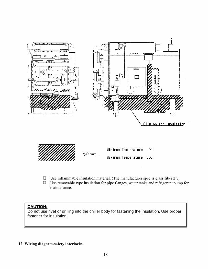
11.Insulation
18
Use inflammable insulation material. (The manufacturer spec is glass fiber 2”.) Use removable type insulation for pipe flanges, water tanks and refrigerant pump for
maintenance.
12. Wiring diagram-safety interlocks.
CAUTION: Do not use rivet or drilling into the chiller body for fastening the insulation. Use proper fastener for insulation.

19
1) Refer to the attached wiring diagram. 2) The main power panel is to be supplied by customer. 3) Wire between main control panel and AD Chiller control panel as shown in the diagram (- - -).
This is field wiring by customer. 4) Use wire size larger than 2mm2 per each chiller for power supply for the main chiller control
panel. Use wire size larger than 1.25mm2 for interlocking wiring. 5) Use proper wire terminals. 6) Each control panel has to be appropriately grounded. 7) Determine the wire size for the main control panel power supply by considering the all motor
KW used in the panel. 8) The motor KW should determine the type of pump starter. 9) Vacuum pump starts automatically. Do not turn off the power supply while the chiller is off
duty. 10) “Winter Mode” is used to prevent the chiller from freezing while it is off duty by running the
cooling water pump and chilled water pump automatically when the ambient temperature falls below freezing. Set operating mode of the chilled water pump and cooling water pump in the main control panel to “AUTO” and select WINTER MODE to RUN on the chiller control panel.
11) On wiring diagram in section 12, the cooling water pump stops when the chiller alarms on hot water buffer tank level. If running the cooling water pumps, while level alarm is activated, is required, jump terminal 5 and 6 as shown in the wiring diagram.
12) If the operating mode of the cooling water pump and the chilled water pump are set at “MANUAL” on the main control panel, they do not stop on hot water buffer tank level alarm.
13) Upper and lower level float switches are required for the hot water buffer tank (open type). These float switches are installed and wired by customer.

20

21
13.Criteria for cooling water and refrigerant water quality.
As per Japan Refrigeration Association J.R. A9001-1980
Tendency Items Criteria Corrosion Scale
Criteria for Refrigerant
PH at 25oC 6.5-8.0 ○ ○ 6.0-8.0 Conductivity at 25oC [μ./cm]
Less than 800 ○ ○ Less than 200
Chlorine ion CL-
[ mgCL-/l] Less than 200 ○ Less than 50
Sulfuric acid SO42-
[mgSO42/l]
Less than 200 ○ Less than 50
Calcium(PH4.8) [mg CaCO3/l]
Less than 100 ○ Less than 50
Hardness [mg CaCO3/l]
Less than 200 ○ Less than 50
Ferrous Fe [mg Fel]
Less than 1.0 ○ ○ Less than 0.3
Sulfur S2-
[mgS2-/l] 0 ○ ○ 0
Ammonium NH4+
[mgNH4+/l]
Less than 1.0 ○ Less than 0.2
Silica SIO2 [mg SIO2/l]
Less than 50 ○ Less than 30

22
Q & A
1. I would like to discuss with you the pros and cons of a closed hot water buffer tank versus an open tank design. In a solar collector system, glycol evaporation would be a problem in an open tank system if the solar array is not isolated from the tank with a heat exchanger. While it is possible to install a closed buffer tank system, we do not have any details. An automatic bleed device will be required for the closed type tank as you know the cooling water trapped to the hot water side will expand. This expanded water can be transferred to the cooling water side again. In this case the adsorption chiller will be inside of closed cycle completely. The chiller will be out of problem from water fouling or corrosion. 2. Do you have an estimate of the rate overflow for the NADAC-20 chiller? It is my understanding that there will always be a net volume gain on the hot water side. This argues for placing a heat exchanger between the solar field and the hot water loop to prevent dilution as spillage of the glycol solution. Estimated overflow rate is 0.023 gpm for a 20 ton chiller. In a closed system, over flow can be eliminated. 3. Is it necessary to have a chilled water expansion tank if you have a holding tank in the system? A chilled water expansion tank is not needed if the chilled water holding tank is sized to handle the normal chilled water expansion. 4. Please provide the pipe sizes for the external piping connections for the chilled water, hot water, and condenser water as they are not indicated on the drawings in the manual. Please see individual chiller submittals. 5. In section 7.11 thermometers are discussed. Are thermometers provided internally for the chilled water inlet and outlet lines? Rather than oil, can thermal paste be used in the thermo wells? Regarding the chilled water inlet and outlet thermometers, the AD Chiller is equipped with temperature sensors and displays the readings at the chiller control panel. You may want to install precision dial type thermometer without thermo well in the chilled water system as described in section 7-11 to verify control panel readings. Thermal paste can be used in the thermo wells. 6. In section 12, the wiring diagram is not clear as to what is internal versus external to the assembly and what parts are factory versus field wired. The left side of the diagram is factory furnished and the right side is field wired.

23
TROUBLESHOOTING
Issue Check Solution Chiller won’t run. Hot Water Inlet Temp
Refrigerant Flow Alarm External Tank Level Switch
If hot water temperature is above 200 F, the chiller will force the hot water bypass valve open so that hot water never enters the chiller. Bring the hot water temperature down and the chiller will start. The chiller will not run if it does not have proof of chilled water flow. Confirm that the chilled water pump is moving water at the chiller. Recalibrate the sensor if required. If the tank level is too high, the external switch will prevent the chiller from operating (this is an optional feature).
Very long cycle time Hot Water Inlet Temp The chiller may be set up to look at return hot water temperatures. If the hot water temperature is below the setpoint, the chiller will wait until the hot water temperature rises before it starts a new cycle.

24
`
For Standard Specification
2011, August Ver.3.1.
Power Partners, Inc.

25
Important notes for safety
Please read this manual before operating the Adsorption) Chiller (AD Chiller).
All cautions and warning below contain safety information. Any personnel who operate the chiller must follow these safety instructions.
Sign Contents
Warning Neglecting will result in major damage or fatal accident.
Caution Neglecting may result in severe accident or injury.
• User must keep this manual in a convenient location for easy to access. All new operators of this AD Chiller, must be provided with adequate training and guidance as per this Operation Manual and all safety and operating precautions understood, prior to the chillier operation.
• Keeping the manual is user’s responsibility. In the event that the manual is lost, damaged, or stolen, contact a distributor or nearest factory authorized service center for replacement.
I. Precautions for machine operation.
Warning 1) When abnormal odor is detected around the chiller, shut down the chiller
immediately. Then turn off the power and contact A distributor or nearest authorized service center. Ignoring this warning will result in damaging the chiller, short-circuiting, and fire.
2) Do not put fingers into rotating devices such as pulley for vacuum pump. Ignoring this warning will cause injury.
3) Prior to servicing the vacuum pump, confirm that the power supply is locked-out. The vacuum pump runs and stops automatically. Ignoring this warning will cause injury.
4) Prior to servicing the chilled water pump and the cooling water pump, confirm that the power supply is locked-out. They may operate automatically. Ignoring this warning will cause injury.
5) Do not use the main circuit breaker to start/stop the chiller. Ignoring this warning will cause short circuiting and fire.
6) Do not use any refrigerant, other than water, as a refrigerant. Ignoring this warning will cause fire or possible explosion.
Caution 7) Do not touch any the electrical devises including control switches with wet
hands. Ignoring this caution may cause electric shock. 8) Do not touch vacuum pump while operating or immediately after the shut

26
down. Ignoring this caution may cause burning. 9) Do not wash down the chiller with water. Ignoring this caution may cause
short-circuiting and fire. 10) Use only factory specified O.C.R. (Over Current Relay). Ignoring this caution
may cause short-circuiting or fire. 11) Keep flammable material away from the chiller. Do not directly spray
flammable paint while the chiller is operating. Ignoring this caution may cause fire.
12) All enclosures for control panels and distributor panels must be kept closed at all times. Ignoring this caution may cause short-circuiting or fire.
13) Do not force the vacuum pump to run by closing the main starter contactor by hand. Ignoring this caution may cause short-circuiting, fire, and mechanical damage on the pump.
14) Cooling/hot water in the system must not be used for consumption. Ignoring this caution may cause health hazard.
15) Do not change the setting of safety/protection devices. Ignoring this caution may damage the chiller and cause an accident such as fire.
16) Do not touch high temperature side of the chiller. Ignoring this caution may cause burning.
II. Precautions for maintenance, servicing and moving.
Warning 17) Contact a distributor or authorized service center for service and repair.
Ignoring this warning will result in accidents such as fire, short-circuiting, and damage to mechanical parts.
18) Do not modify the chiller without factory authorization. If the chiller is modified without authorization, factory will void the warranty and disclaim any liability caused by modification. Ignoring this warning will cause fatal accident.
19) Contact a distributor or factory authorized service center when relocating the chiller. Ignoring this warning will cause malfunction of the system, short-circuiting, and fire.
Caution 20) Do not bypass the protective switches for operating the chiller. Ignoring this
caution may cause fire or explosion. 21) Do not change factory settings of safety and protection devices. Ignoring this
caution may cause fire.

27
Table of Contents
1. Introduction 2. Installation. 3. Adsorption Chiller (AD Chiller) layout. 4. Important information for safe chiller operation. 5. Procedures for the chiller start and stop. 6. Chiller interlock and alarms and what to do to reset. 7. Butterfly valve malfunction-cause and remedy. 8. Flow chart-Starting sequence. 9. Flow chart-Stopping sequence. 10. Locations of air purge and drain valves. 11. Procedure for air purging and draining. 12. Procedure for long term shut down of the chiller and resuming
operation. 13. Procedure for operating vacuum pump. 14. Charging refrigerant. (Water) 15. Procedure for changing the setting of temperature controller. 16. Refrigerant pump. Appendex-1. Criteria for cooling water and refrigerant quality.

28
1. AD (Adsorption) Chiller Introduction.
This Adsorption Chiller (AD chiller) contains only water as a refrigerant and proprietary permanent silica gel (lasts 30 years) as an adsorbent. The evaporator section cools the chilled water by the refrigerant (water) being evaporated by adsorption on to the silica gel in one of two adsorbent chambers. It can produce chilled water temperatures of less than 38oF with hot water temperatures ranging from 194oF to as low as 122oF. The hot water regenerates the silica gel in the second of the two adsorbent chambers. The water vapor released from the silica gel by the hot water will be condensed in the condenser section, which is cooled by cooling water, such as from a cooling tower.
This is an innovative process of using recovered waste heat energy and then utilizing that energy to attain chilled water. Proper use of the chiller, based on this Operation Manual, will enable the user to enjoy long-term operational reliability. This is achieved by simple construction, relatively maintenance free operation, and a high quality of engineering and manufacturing. .
2. Installation. 2-1. Receiving
Confirm the following upon receiving the AD Chiller. (1). All items on the packing list. (2). All accessories on the list. (3). Freight damage, loose bolts and nut, or detached items. 2-2. Installation (Refer to “Installation Manual”)
Field installation, water piping, insulation, wiring, and air piping are to be completed as per “Installation Manual”. Protect the AD chiller and water piping during the field installation.
CAUTION: This Operation Manual is only applicable for the system control panel wired as per wiring diagram shown in section 12 of “Installation manual”.

29
3. Machine layout drawing. – See your submittal drawings for specific dimensions and foundation details.

30
4.Important information for safe chiller operation. 4-1. Power supply
Do not turn off the power supply even if the AD Chiller is either stopped briefly due to satisfying load conditions or in a long term shut down for the following reasons:
1) The vacuum pump runs automatically, by timer, regardless of the AD Chiller operating status. 2) The AD Chiller monitors ambient temperature and automatically runs the cooling water and
chilled water pumps to prevent the chiller from freezing. 3) The AD Chiller monitors the hot water buffer tank level regardless of operating status.
4-2.Capacity Controls The AD Chiller capacity is controlled by monitoring the temperatures of chilled water inlet/outlet and refrigerant to 0%, 25%, 40%, 55%, 70%, 85% and 100% of chiller capacity. This enables the chiller to supply the chilled water at a stable temperature regardless of the chiller load. 4-3. Hot water buffer tank. Unless the heat source has an enough capacity to supply constant hot water or it has 2-3 times surplus heat capacity against chilling load, installation of the hot water buffer tank is recommended in order to maintain constant chiller capacity. Detail refers to “Installation Manual”. 4-4.Cooling-tower fan control Keeping the cooling water temperature constant is an important factor in maintaining the chiller efficiency. It is generally achieved by precise fan controls on the cooling tower. The AD chiller is equipped with a temperature sensor at the cooling water outlet, which provides output signals to the cooling tower fan control.
Default fan control settings are as follows. Turn ON at 28C[82.4F]cooling water temperature. Turn OFF at 26C[78.8f] cooling water temperature.
4-5. Water quality control Quality of water for the cooling water, chilled water, hot water, and refrigerant must be monitored and controlled as per attached data sheet. (See Appendix 1. Criteria for cooling water refrigerant quality.) This is based on Japanese Refrigeration Association’s guideline JRA9001-1980. 4-6. Strainers on the water line. Install strainer on the hot water and cooling water line as per “Installation Manual” in order to protect the 12 butterfly valve seats. These strainers must be checked periodically to prevent clogging. Also careful and adequate pipe cleaning after the installation will prevent contaminants being left in the system. 4-7. Butterfly valve maintenance. The seats of the Butterfly valves and the seals of the actuators are generally to be replaced with every 3-5 years of operation. Contact A distributor when needed. The seats are exchanged at site or remanufactured valves can be installed in minutes.

31
4-8. Water line design pressure. Design pressure of the water line is 0.5 Mpa (71 psig). Do not operate the chiller beyond the design pressure. 4-9.Flow switch on the chilled water line. Operating the chiller without the chilled water flowing will freeze up evaporator tubing. Blocking of the chilled water flow can be caused by wrong valve operation. The AD Chiller comes with a safety interlock device (flow switch) for the chilled water flow. This device is normally connected in series with the chilled water pump starter contactor as shown on the “Installation Manual”section-12 for redundant safety. 4-10. Hot water tank level switch. If the 12 butterfly valves are incorrectly operated or the valve seat is damaged, the hot water and cooling water will mix. This may cause the hot water tank to excessive over-flow. In order to detect mixing of the two water streams and prevent excessive over-flow from occurring, a temperature sensor is installed on the cooling water line. The hot water line’s temperature normally fluctuates over a wide range of temperatures. This makes it impossible to use the hot water temperature as a trigger for excessive over-flow protection. Therefore, it is required that the level switches be installed on the hot water buffer tank. See “Installation Manual” for details. 4-11.Air supply. Air quality. Dew point lower than –17oC (1.5oF) at atmospheric pressure. Solid less than 5micron(0.2mils) Oil less than 5mgf/Nm3
Main Air Pressure 0.5-0.8Mpa (72 –115psig)
Moisture and contaminants in the supplied air might cause malfunction of butterfly valves, actuators, and solenoid valves. The AD Chiller is equipped with regulator/filter at the air inlet. However, install automatic drain on the air compressor if the filter traps a lot of water.
CAUTION: For an optional air compressor unit with an auto-drain installed on the chiller. Contact a distributor or authorized service center if the chiller is to be installed at high humid and/or coastal environment.
CAUTION: This flow switch is installed and adjusted at factory.
CAUTION: Do not shut off air supply while the chiller is in long term shut down since the chilled water pump and the cooling water pump run automatically in order to prevent the chiller from freezing when the ambient temperature drops below freezing. However, this will not apply if the chiller is to be shut down for more than 1 month. Refer to section 12, “Procedure for long term shut down the chiller and resuming operation.”

32
5.Procedure for the AD Chiller start-up and shut-down. 5-1 Preparation
1) Confirm that the water piping, insulation, wiring, safety interlocks, and air supply are completed as per “Installation Manual”.
2) Confirm that the air pressure regulator is set at 0.5-0.55Mpa(72-79psig). 3) Confirm that the power supply lamp on the chiller control panel is “ON”. 4) Turn on the circuit breakers in the control panel (NFB1 and NFB2). 5) The chiller control touch screen panel operates the AD Chiller. Confirm that the following display
shows up when NFB1 and NFB2 are turned on
6) Main menu is used to set up operating mode and display the status. The buttons will change color indicating when they are active.
Note: Default status of each operating mode is STOP. In order to change the operating mode, hit STOP key first. e.g. NO AUTO to MNUAL YES AUTO to STOP to MNUAL IDLE : When you need Long Term Shut Down, all valves will be open to drain all water out.
7) Check rotating direction of the vacuum pump by hitting vacuum pump MNUAL key. Correct the rotation by swapping two phases if it is turning to opposite direction.
Touch screen needs to be touched for more than 1 second to activate the command.
Hitting this key will display the status of the chiller
CAUTION: If changing the rotation by swapping phases, confirm that the power supply is turned off.

33
8) Power on manually at the power control panel and run all pumps (chiller water, cooling water, and hot water), and the cooling tower. Check to ensure that the pump operation, pressure, flow rate, and temperatures are as per design specification. If operating out of design parameter, stop the system start up and investigate the cause. Do not run the system under abnormal operating conditions.
9) The vacuum pump shut off valve is closed at the factory. Open the valve before starting the
vacuum pump.
10) Now the AD Chiller is ready to start.
5-2. Procedure for commissioning the AD Chiller (Initial start up) (Make sure to complete step 5-1 before start commissioning).
1) Set Refrigerant pump to AUTO position. If the chiller is started without setting operating mode of the refrigerant pump at either AUTO or MANUAL position, the following warning will be displayed.
2) Select “Manual” operating mode at the power control panel and run all pumps and cooling tower. Confirm the flow in each line.
Hit this key to return to Main Menu.
Caution: Air in the system has to be thoroughly purged.

34
3) Select LOCAL mode in the chiller control touch screen panel. STANDBY-RUN will be displayed for 60 seconds followed by RUNNING display as below.
60 sec

35
CAUTION: The following display may be shown after setting the refrigerant pump operating mode to either AUTO or MANUAL. This display indicates that the refrigerant (water) has been adsorbed by the adsorbent during shut down and is causing the low refrigerant level alarm.
Procedures to recover the adsorbed refrigerant (Water.)
1) STOP the chiller. 2) Set all pumps and cooling tower at “MANUAL” operation. 3) Go back to MAIN MENU and set CONFIRM REFRIGERANT to RUN mode. 4) Set vacuum pump to MANUAL 5) Hit the STATUS key at MAIN MENU. Then display will change as below. Normally this procedure will take 10 minutes.
Hit this key to return to Main Menu.

36
4) Since the air inside of the machine will go to the piping, air in the piping must be thoroughly purged. Closed circuit will take longer to purge the air. Refer to section 12 “Procedure for air purging”.
5) If the cooling load is low during the start up, the chiller may be shut down by capacity control. Therefore, make sure that there is sufficient chiller load during the start up.
6) Stop the chiller and run the chilled water pump for 10 minutes, then change operating mode to REMOTE. At power control panel, change operating mode of pumps and cooling tower from “MANUAL” to “AUTO”, then turn on the “AUTO OPERATION” switch at the power control panel. Now it is ready to run the system at normal operation (Automatic).
7) Refer to section 14 “Procedure for operating vacuum pump”, run the vacuum pump for 10 hours.
The process takes about 15 minutes
6) After finishing CONFIRMING REFRIGERANT , return to 5-2 and restart the chiller.
7) If the display does not change to REFRIGERANT CONFIRMED within an hour, check the following.
• Vacuum in the chiller is not low enough. See section 14 Procedure for operating vacuum pump.
• Lack of refrigerant (Water). See section 15 Refrigerant charges. 8) CONFIRM REFRIGERANT will regenerate the adsorbent. After finishing this
process, run the chiller at least 1 hour.
CAUTION: Set WINTER MODE to RUN regardless of season.
Confirming Refrigerant

37
5-3.Procedure for normal operation Start and Stop. 1) Set operating mode as follows. Chiller Control touch screen panel Refrigerant pump AUTO Vacuum pump AUTO Winter Mode RUN Operating Mode REMOTE Power control panel Operating Mode “AUTO” Auto operation switch “ON”
Refers to section 8 “Flow chart starting sequence”.
2) Selecting the “OFF” position of the Auto operation switch at the power control panel will
turn off all pumps except the chilled water pump. This pump will automatically run 10 more minutes after shut down. Refers to section 9 “Flow chart stopping sequence”.
3) If the AD Chiller is to be shut down for more than 1 month, refers to section 12
“Procedure for idling the chiller and resuming operation”.
CAUTION: While the chiller is shut-down, the vacuum pump is automatically run at regular intervals by a timer in the chiller control panel. The chilled water pump and cooling water pump will also be run automatically in order to prevent the chiller from freezing. Do not turn off the main power supply while the chiller is idle.

38
6.Chiller interlocks /alarms and what to do. There are 11 protections for the AD chiller.
a) Hot water level abnormal (Either high or low) b) Cooling water abnormal c) Chilled water flow abnormal d) Air pressure abnormal e) Level abnormal f) Evaporator temperature abnormal g) Inverter abnormal h) Refrigerant level abnormal i) Refrigerant pump abnormal j) Vacuum pump abnormal k) Vacuum pressure abnormal
“Hot water tank abnormal”, “Cooling water abnormal”, “Chilled water flow abnormal”, “Air
pressure abnormal”, ‘Evaporator temperature abnormal”, “Inverter abnormal”, “Refrigerant level abnormal”, protections are activated while the chiller is running. They will alarm and shut down the chiller at the same time.
“Level abnormal” is activated regardless of chiller operation status. This will alarm and shut down the chiller and chilled water pump at the same time.
“Vacuum pump abnormal” and “Vacuum pressure abnormal” will provide alarm signal only. The chiller will continue to run.
6-1 Procedure for identifying the type of alarm. a) “Vacuum pump abnormal” and “Vacuum pressure abnormal” will be displayed as follows.
CAUTION: When restarting the chiller after resetting the alarm, reset the operating mode of vacuum pump and refrigerant pump to AUTO position.
Vacuum pump abnormal Vacuum pressure abnormal
Chiller continues to run.
Showing abnormal vacuum.
Go to the Alarm Screen and hit the reset key to reset the alarm. Also alarm display will be erased. Check the contents of alarm before hitting the reset key.

39
b) Other abnormal alarms will be displayed in the ALARM –STOP display as below, at the same time the chiller is shut down.
Recent alarms are highlighted in pink. Hitting the Ack Alarms List button will acknowledge the alarm and change the color from pink to blue. To clear the alarm you must hit the reset button.

40
6-2. What to do at abnormal 6-2-1.Hot water tank level abnormal and cooling water abnormal
Malfunction of butterfly valves (V1-V12) and /or damaged valve seatings may cause mixing of hot water and cooling water, which will result in changing the water level in the hot water tank, expansion tank, and/or temperature rise in the cooling water. Later may damage the cooling tower.
Install high/low level switches and wire them as per “Installation Manual”. This will protect the chiller from abnormal hot water tank levels. A factory installed temperature sensor at the cooling water outlet will detect abnormal cooling water and protect the chiller.
No. Check Point Action 1 Air supply…Pressure
setting and loose connection such as hose nipple, clamps…etc
1) Check the air pressure …More than 0.5Mpa(60psig)
2) Repair damaged connection and hose. 3) Clean air filter.
2 Setting of temperature sensor at cooling water outlet.
1) Default setting is to open the contact when 50oC (122F) water flows for 1 minute. Change the setting as per actual chiller operation.
2) Check if the cooling water flow rate is reduced.
3) Check if cooling water temperature is normal.
3 Butterfly valve operation 1) Check by-pass valves as per section-7 “Butterfly valve malfunction-check and remedy”.
4 Butterfly valve seating 1) Check that the Butterfly valves follow the sequence as per section7- (6) Butterfly valve operating mode table by measuring the actual temperature of the valve unit.
2) For suspected leaky valve, check the valve seating.
If the chiller cannot be rest after checking 1 through 4, contact HIJC USA or A distributor
for more assistance.
CAUTION: When the chiller is shut down on alarm, confirm the type of alarm before resetting. Check the chiller as described below. Do not restart the chiller without eliminating the cause.

41

42
6-2-2. Chilled water flow abnormal.
Operating the chiller without flowing chilled water will cause rupturing of the evaporator tubes. A flow switch is installed on the chilled water outlet and is wired in series with the chilled water pump starter contactor for providing redundancy in the evaporator protection.
No Check Point Action 1 Check the chilled
water pump. 1) Check O.C.R. (Over Current Relay) and its
setting. 2) Run the pump by changing the operating mode to
“MANUAL” at main control panel and check that the pressure and flow rate are normal.
2 Check the control panel wiring.
1) Turn off NFB-2. Check for continuity between terminal COM and 18 after disconnecting external wire connections and manually running the chilled water pump.
2) No continuity indicates a problem in the chilled pump safety interlock wiring.
3) Showing continuity indicates loose terminal connections in the main chiller control panel.
3 Check flow switch. 1) Turn of NFB2. Check for continuity between terminal 18 and X3 by disconnecting external wire connections and manually running the chilled water pump.
2) No continuity indicates a problem with the flow switch and its wiring.
Visually inspect flow switch wiring. Remove flow switch and inspect for
mechanical damage. 1) Showing continuity indicates loose terminal
connections in the chiller control panel. In case the chiller cannot be rest after checking 1 through 3, contact A distributor or nearest
authorized service center for more assistance.
CAUTION: When the chiller is shut down on alarm, confirm the type of alarm before resetting the alarm. Check the chiller as described below. Do not restart the chiller without eliminating the cause for the alarm.

43
6-2-3. Air pressure abnormal Constant main air pressure at 0.5MPa – 0.8MPa(72-115psig) at the air pressure
regulator/filter inlet is required for the chiller. Lowering the pressure will cause malfunction of the pneumatic actuator used for by-pass valves.
NO Check point Action 1 Check air
pressure. 1) Adjust the pressure regulator to 0.5-0.55 Mpa
(72-79 psig). Check air compressor as well. 2) Clean filter at air inlet.
2 Check the setting of air pressure switch. Default setting 0.35 Mpa (50 psig).
1) Check that the pressure switch cuts off at the setting by lowering the air pressure.
2) If the setting is out, readjust it to 0.35 Mpa (50 psig) by adjusting the set screw on the switch.
3 Check wiring of chiller control touch screen panel.
1) Turn NFB2 off and check that there is no continuity between COM and X4.
4 Check air hose and connection.
1) Repair damaged connection or hose.
In case the chiller cannot be rest after checking 1 through 4, contact A distributor or nearest authorized service center for more assistance.
CAUTION: When the chiller is shut down on alarm, confirm the type of alarm before resetting. Check the chiller as described below. Do not restart the chiller without eliminating the cause.

44
6-2-4. Level abnormal
A float level switch is installed at the evaporator. If rupturing of the evaporator tubes occurs, this level switch will detect the water level rise in the evaporator and shut down the chiller. This protection device works regardless of chiller operation status.
A special consideration is needed for floor grouting because the chiller weight can be doubled if rupturing of the evaporator tube occurs.
Procedure to recover from the level abnormal alarm (1). Open by-pass valve on hot water line and cooling water line (Both customer Installed) and close shut off valves (Customer installed). (2). Close chilled water inlet valve. (Customer installed). (3). Open the drain valve and air purge valves on the condenser, adsorbent chamber, and evaporator. Refer to “Installation Manual” for the location of these valves. (4). Open the chiller control panel and make sure the #5 input lamp of the main sequencer is off. Input #5 ON: Level Normal OFF: Level Abnormal (5) Stop air supply and reduce air pressure setting to 0 MPa. (6). Contact A distributor or nearest authorized service center.
CAUTION for optional roof top unit: This optional type is equipped with two level switches, automatic shut off valves at chilled water inlet and outlet, automatic drain valves for the condenser, adsorbent chamber, and evaporator chamber, as well as a vacuum breaking valve for the chiller. When the level abnormal occurs, it alarms and shuts down the chiller. At the same time, it shuts down the chilled water pump and closes the chilled water inlet and outlet valves, opens the drain valves, and breaks the chiller vacuum.
CAUTION: Alarm reset works only after draining all water in the evaporator. Drain all water before resetting alarm. After finishing the procedure above, contact A distributor or nearest authorized service center for further instruction.

45
6-2-5. Evaporator temperature abnormal
The evaporator pressure is kept low during the chiller operation. Further lowering of the pressure will cause freezing of refrigerant (water) and consequential tube rupturing.
“Evaporator Temperature Abnormal” protection device measures the evaporator temperature and is used to protect the evaporator from being frozen.
A float level switch is provided in the evaporator to monitor the refrigerant level. If this level does not become high enough within 11 minutes of chiller start up, it shuts down the chiller due to the possibility of frozen refrigerant.
No Check Point Action 1 Spraying
refrigerant 1) Run the refrigerant pump at “MANUAL”
mode and check it through the sight glass for adequate refrigerant dispersion.
2) If there is not an adequate spraying, contact A distributor or nearest authorized service center for instruction.
2 Check wiring of chiller control panel.
1) Turn NFB2 off. Check continuity between COM and X11 (remove external wire connections) if it shows continuity, check loose terminal connection.
2) Showing no continuity indicates possible wiring or float switch problem.
In case the chiller cannot be rest after checking 1 through 2, contact A distributor or nearest authorized service center for more assistance.
CAUTION: When the chiller is shut down on alarm, confirm the type of alarm before resetting. Check the chiller as described below. Do not restart the chiller without eliminating the cause.

46
6-2-6. Refrigerant charge abnormal
A float level switch is installed at the bottom of the evaporator to prevent the refrigerant pump from running on a low refrigerant level.
No Check Point Action 1 Refrigerant charge 1) Check the level through sight glass.
2) Charge the refrigerant as needed. (Refers to section 15 Refrigerant (water) charge.
2 Check the wiring of chiller control panel
1) Turn off NFB2. Check continuity between COM and X12 (remove external wire connections). Showing continuity indicates loose terminal connection.
2) No continuity indicates float or its wiring problem. Check the wiring and float switch.
In case the chiller cannot be rest after checking 1 through 2, contact A distributor or nearest authorized service center for more assistance.
CAUTION: When the chiller is shut down on alarm, confirm the type of alarm before resetting. Check the chiller as described below. Do not restart the chiller without eliminating the cause.
CAUTION: Refrigerant level abnormal alarm may come up during the start up after long term shut down. The refrigerant (water) may have been adsorbed by the adsorbent during shut down and is causing the low refrigerant level alarm.

47
6-2-7. Inverter abnormal This alarm comes from the inverter for the refrigerant pump motor. If there is an abnormal
current, voltage, or load, in the inverter, it shuts down both the refrigerant pump and the chiller in order to protect the inverter.
Turning off NFB1 and NFB2 can reset this alarm.
No Check Point Action
1 Over current is displayed as OC1, OC2 and/or OC3 on inverter.
1) Check line voltage. 2) Check loose terminals on the pump. 3) Check the settings.
2 Over voltage is displayed as “OV” on the inverter.
1) Check line voltage.
3 Overloading is displayed as OH1 on the inverter.
1) Check refrigerant pump for damage. 2) Contact A distributor or nearest authorized
service center.
In case the chiller cannot be rest after checking 1 through 3, contact A distributor or nearest authorized center for more assistance.
CAUTION: When the chiller is shut down on alarm, confirm the type of alarm before resetting. Check the chiller as described below. Do not restart the chiller without eliminating the cause.

48
6-2-8. Refrigerant pump abnormal
Operating mode of the refrigerant pump must be either “AUTO” or “MANUAL”. If this setting is lost during the chiller operation, it shuts down the chiller.
Operating the chiller without the refrigerant pump will cause the chiller to freeze. No Check Point Action
1 Check the touch screen display for operating mode setting.
1) Set operating mode. 2) If this alarm continues to happen, contact A
distributor or authorized service station.
In case the chiller cannot be rest after checking 1, contact A distributor or nearest authorized service center for more assistance.
CAUTION: When the chiller is shut down on alarm, confirm the type of alarm before resetting. Check the chiller as described below. Do not restart the chiller without eliminating the cause.

49
6-2-9. Vacuum pump abnormal. This is to protect the vacuum pump motor from over current. This shuts down the vacuum
pump only. The chiller continues to operate.
No Check Points Action
1 Pump oil level. 1) Check oil level as per section 14-3. Vacuum pump oil level check. (It should be at center of sight glass)
2 Pump jammed with foreign material or seizure.
1) Check to see if the pump rotates. a) Set operating mode to STOP. b) Turn off NFB1 and NFB2. Pull V belt by hand
and check to see if the pump rotates. c) If it is hard to turn, then replace pump oil and
run it by setting operating mode to MANUAL. 2) If not rotating at all, contact A distributor or
nearest authorized service center. 3 Lowering ambient
temperature will increase oil viscosity, which causes higher running current.
1) Repeat 2-(1) several times.
Alarm can be reset by hitting OCR reset button on the vacuum pump starter contactor in
the main control panel, and ALARM RESET key on the display. In case the chiller cannot be reset after checking 1 through 3, contact A distributor
or nearest authorized service center for more assistance.
CAUTION: The chiller continues to operate while only the vacuum pump shuts down. When this alarm happens, stop the chiller manually and inspect the vacuum pump.
CAUTION: Before inspecting the vacuum pump, it is imperative to turn off NFB1 and NFB2 and set operating mode to STOP.

50

51
6-2-10. Vacuum pressure abnormal This is to protect the vacuum pump and motor by the vacuum sensor monitoring the evaporator
pressure. No Check Point Action
1 Vacuum pump V- belt damage.
1) Change damaged V belt. 2) Check the vacuum pump as section 6-2-9.
2 Slipping V- belt. 1) Check V- belt slip by running the pump. 2) If the belt is slipping, adjust the V-belt tension.
In case the chiller cannot be reset after checking 1 through 2, contact A distributor
or nearest authorized service center for more assistance. 6-2-11. Chiller capacity abnormal.
If the chiller performance falls below specification by reducing COP or capacity, check for one or more of the following potential problems:
(1) Check that the hot water and cooling water temperature and flow rates are as per
design specification (a). A lower than specified hot water temperature will lower the chiller capacity. (b). A higher than specified cooling water temperature will lower the chiller capacity. (c). A lower than specified flow rate of the hot or cooling waters, will lower the chiller
capacity.
(2) Check that the chilled water flow rate is as per design specification. (a). A higher than specified flow rate will reduce the delta T across the chiller. Check and compare design and actual delta-T and the flow rate.
(3) Check that the vacuum pressure is as per factory specification. a) A higher than specified vacuum pressure will reduce the capacity. Check the pressure
as per section 13-4 “Vacuum pressure control”. If the vacuum pressure is higher than standard operating condition, check the vacuum pump as per section 13 “Procedure for operating vacuum pump” and run the pump for 10 hours.
In case the vacuum pressure is still high after inspections and adjustments, contact A distributor or nearest authorized service center for further instruction.
CAUTION: The chiller continues to operate while only the vacuum pump shuts down. When this alarm happens, stop the chiller manually and inspect the vacuum pump.
CAUTION: Before inspecting the vacuum pump, it is imperative to turn off NFB1 and NFB2 and set operating mode to STOP.

52
(4). Check that the refrigerant spray over the evaporator tubing adequate.
a) Dry evaporator tube surface as a result of inadequate refrigerant spray will reduce the rate of heat exchange. Check refrigerant spray though the sight glass.
b) If there is a problem in the refrigerant spray, it may indicate problems with the refrigerant pump. Contact A distributor or authorized service center for further instruction.
7.By-pass valve malfunction-Causes and remedies.
There are several causes for malfunction of water by-pass valves. (V1-V12)
(1). Solenoid valve malfunction. (2). Actuator malfunction.
(3). Valve malfunction.
53
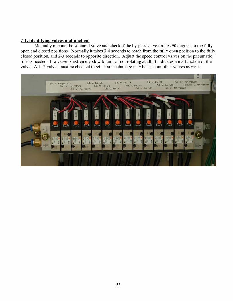
7-1. Identifying valves malfunction. Manually operate the solenoid valve and check if the by-pass valve rotates 90 degrees to the fully
open and closed positions. Normally it takes 3-4 seconds to reach from the fully open position to the fully closed position, and 2-3 seconds to opposite direction. Adjust the speed control valves on the pneumatic line as needed. If a valve is extremely slow to turn or not rotating at all, it indicates a malfunction of the valve. All 12 valves must be checked together since damage may be seen on other valves as well.

54
7-2.Checking-solenoid valve Disconnect all pneumatic lines on the valves and manually operate the solenoid valves one by one. By manually opening the solenoid valve, check if the air supply to the valve changes one after another as per table below. If it is not supplying the air to the valve at all, the solenoid valve is not working properly. It should be checked or replaced. VR5 SV1 SV2 SV3 SV4 SV5 SV6 SV7 SV8 SV9 SV10
S/V No. Valve Name S/V No Valve Name VR5 Vapor by-pass damper SV6 V8 SV1 V1, V3 SV7 V9 SV2 V2, V4 SV8 V10 SV3 V5 SV9 V11 SV4 V6 SV10 V12 SV5 V7
Manual Switch

55
7-3. Actuator check. Remove the actuator from the valve body and check the shaft rotation by manually opening the solenoid valve. If the actuator shaft does not turn, it is an actuator malfunction. It should be replaced.
7-4. Valve body check If 7-1, 2 & 3 are OK, check valve body to determine if the valve stem turns.
(a) Smooth shaft rotation. (b) Hard to move. (c) Does not move at all.
For (a), the valve seating may be temporarily jammed with sediment or debris. Open the valve and clean the seating. For (b) and (c), larger foreign material may be jammed at the valve seat or valve stem. Remove the valve from the chiller and clean it or replace.
7-5. If the problem continues after checking 7-1 to 4, contact A distributor or nearest authorized service center for further instruction.
Speed controller. Close to open.
Speed controller. Open to close
Actuator body.

56
7-6. Valve operating mode. Chiller Operating Cycle
Cycle A B C D E F
No1.Heat Exchanger
Regenerating
Prep. Adsorbing
Adsorbing Prep. Regeneration
No.2 Heat Exchanger
Adsorbing
Heat recovery
Prep. Regeneratio
n
Regeneration
Heat Recover
y Prep. Adsorbing
Time (Sec.) 373 30 17 373 30 17
Valve status table for each cycle and level alarm shut down and winter mode.
V 1
V 2
V 3
V 4
V 5
V 6
V 7
V 8
V 9
V 10
V 11
V 12
By-pass damper
Normal Operation Except level abnormal
X X X X X X X ○ ○ X ○ ○ X
Normal Operation ○ X ○ X X X ○ X ○ X X○* X X Regenerating X X X X X X ○ ○ ○ X ○ X X Adsorbing ○ X ○ X X X X X ○ X X ○ X
A Capacity Control Mode Regenerating/Absorb X X X X X X X ○ ○ X ○ ○ X
B X X X X X X X ○ ○ X ○ ○ ○ C X X X X ○ ○ X X ○ X ○ X X
Normal operation X ○ X ○ X ○ X ○ X X X○* X X Regenerating X X X X X ○ X ○ ○ X ○ X X Adsorbing X ○ X ○ X X X ○ X X X ○ X
D Capacity control Mode Regenerating/Absorb X X X X X X X ○ ○ X ○ ○ X
E X X X X X X X ○ ○ X ○ ○ ○ F X X X X X X ○ ○ X ○ ○ X X
Winter mode-RUN X X X X X ○ ○ ○ ○ X ○ X X Winter Mode Long term shut-down ○ ○ ○ ○ ○ ○ ○ ○ ○ ○ ○ ○ X Level abnormal alarm shut down X X X X ○ X X X X X ○ ○ X
Capacity control mode in A and D cycle: When the chiller is operating on the capacity
control. “○” indicate valve OPEN, ”X” indicate valve CLOSED,”*” indicates releasing process
during releasing mode.
57
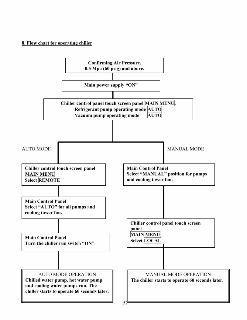
8. Flow chart for operating chiller AUTO MODE MANUAL MODE
Confirming Air Pressure. 0.5 Mpa (60 psig) and above.
Main power supply “ON”
Chiller control panel touch screen panel MAIN MENU. Refrigerant pump operating mode AUTO Vacuum pump operating mode AUTO
Chiller control touch screen panel MAIN MENU Select REMOTE
Main Control Panel Select “MANUAL” position for pumps and cooling tower fan.
Main Control Panel Select “AUTO” for all pumps and cooling tower fan.
Main Control Panel Turn the chiller run switch “ON”
AUTO MODE OPERATION Chilled water pump, hot water pump and cooling water pumps run. The chiller starts to operate 60 seconds later.
Chiller control panel touch screen panel MAIN MENU Select LOCAL
MANUAL MODE OPERATION The chiller starts to operate 60 seconds later.

58
9. Flow chart-Stopping chiller 9-1. AUTO (REMOTE) Mode. 9-2 MANUAL Mode Run the chilled water pump for 10 minutes after stopping the chiller.
Main Control Panel Turn off AUTO operation switch.
Hot water pump, cooling water pump and cooling tower fan stop.
Chiller stops
Chilled water pump stops 10 minutes after the chiller stops.
Automatic Operation
Main Control Panel Stop hot water pump, cooling water pump and cooling tower fan.
Chiller control touch screen panel MAIN MENU Set chiller STOP
Main Control Panel Chilled water pump “STOP”

59
10.Locations of air purge valves and drain valves.
Drain valves and air purge valves are installed as above at factory. Field drain and air purge
piping is by customer.
60
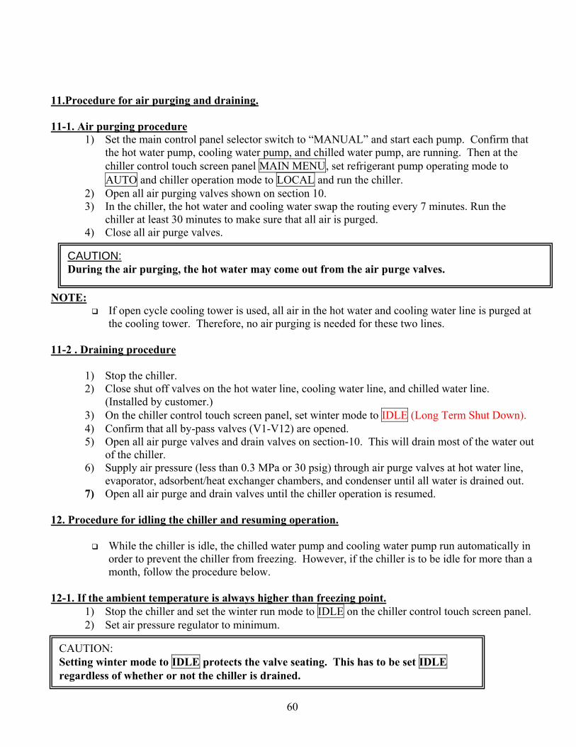
11.Procedure for air purging and draining. 11-1. Air purging procedure
1) Set the main control panel selector switch to “MANUAL” and start each pump. Confirm that the hot water pump, cooling water pump, and chilled water pump, are running. Then at the chiller control touch screen panel MAIN MENU, set refrigerant pump operating mode to AUTO and chiller operation mode to LOCAL and run the chiller.
2) Open all air purging valves shown on section 10. 3) In the chiller, the hot water and cooling water swap the routing every 7 minutes. Run the
chiller at least 30 minutes to make sure that all air is purged. 4) Close all air purge valves.
NOTE:
If open cycle cooling tower is used, all air in the hot water and cooling water line is purged at the cooling tower. Therefore, no air purging is needed for these two lines.
11-2 . Draining procedure
1) Stop the chiller. 2) Close shut off valves on the hot water line, cooling water line, and chilled water line.
(Installed by customer.) 3) On the chiller control touch screen panel, set winter mode to IDLE (Long Term Shut Down). 4) Confirm that all by-pass valves (V1-V12) are opened. 5) Open all air purge valves and drain valves on section-10. This will drain most of the water out
of the chiller. 6) Supply air pressure (less than 0.3 MPa or 30 psig) through air purge valves at hot water line,
evaporator, adsorbent/heat exchanger chambers, and condenser until all water is drained out. 7) Open all air purge and drain valves until the chiller operation is resumed.
12. Procedure for idling the chiller and resuming operation.
While the chiller is idle, the chilled water pump and cooling water pump run automatically in order to prevent the chiller from freezing. However, if the chiller is to be idle for more than a month, follow the procedure below.
12-1. If the ambient temperature is always higher than freezing point.
1) Stop the chiller and set the winter run mode to IDLE on the chiller control touch screen panel. 2) Set air pressure regulator to minimum.
CAUTION: During the air purging, the hot water may come out from the air purge valves.
CAUTION: Setting winter mode to IDLE protects the valve seating. This has to be set IDLE regardless of whether or not the chiller is drained.

61
12-2 If the ambient temperature drops below freezing point
1) Close shut off valves for the hot water, cooling water, and chilled water line (Customer installed) 2) Drain water as per instruction section 11-2 Draining Procedure. 3) Open drain valves and air purge valves until next season. 4) Set air pressure regulator to minimum.
12-3 Preparation for restarting the chiller
1) Set air pressure regulator to 0.5 Mpa (60 spig) and set winter mode to either STOP or RUN. 2) Check all 12 by-pass valves (V1-V12) as per section 7.”By-pass Valve malfunction-causes
and remedies.” 3) Restart the chiller as per section 5-2 “ Procedure for commissioning the AD Chiller.”
13. Procedure for operating the vacuum pump. 13-1. Procedures
During commissioning the chiller, run the vacuum pump manually for 10 hours. Also run it manually during the preseason start up.
1) Preparation a) Check if the oil level in the sight glass is at the center of sight glass.
2) Auto mode operation a) At the chiller control touch screen panel, set vacuum pump operating mode to AUTO.
This setting enables the pump to run automatically. b) Default vacuum pump-run schedule is to run from 01:00AM for 1 hour on every Monday,
Wednesday, and Friday. (This schedule can be changed.) 3) Manual mode operation
a) Running the vacuum pump while the chiller is running is very effective to lower the pressure.
b) At the chiller control touch screen panel, set the vacuum pump operating mode to MANUAL. This setting enables the pump to run manually.
c) After running the vacuum pump manually, change operating mode to AUTO. Normally the vacuum pump is set to AUTO mode.
13-2. Checking the system vacuum.
1) Check the system vacuum while the vacuum pump is running. 2) No.1 Vacuum S/V will open 1 minute after the vacuum pump runs and No.2 vacuum S/V will
open 5 minute after the pump runs. Check the system vacuum after No2 S/V is opened. 3) The system vacuum during high demand season (summer) is approximately 40-50 Torres
(27.26-28.35” hg)
CAUTION. Do not turn off the power supply since vacuum pump runs automatically while the chiller is idle.

62
13-3.Inspection and maintenance.
1) Oil level check a) Check oil level once a month. Check the oil level whenever “Vacuum pump abnormal”
and “Vacuum pressure abnormal”, are displayed. b) When the oil level is lower than sight glass centerline, stop the pump to add oil.
2) Oil charge a) Add new oil in the amount of 200-300cc(7-10 oz) every 3 months of chiller operation.
3) Oil specification Use oil with the viscosity range as below.
40oC 60-70CST 100oC 7-9 CST Oil charged at factory is “IDEMITSU DAPHNE SUPERACEPACK 68”
4) Inspect the vacuum pump once a year or whenever the vacuum pump performance is not satisfactory. a) Check oil for contaminants and water. b) Check V-belt tension and damage. c) Check hose, hose clamp, and hose nipple for possible damage.
d) Check the vacuum pump performance as below I. Close vacuum pump shut off valve (Normally open).
II. Run the pump manually for 1 hour. III. Check the vacuum pressure. It should be +/- 50 Torres (28”hg)
In case the pressure does not lower to the specified level, the vacuum pump may need a
complete overhaul. Contact A distributor or nearest authorized service center for detail. Allow 2-3 weeks for complete overhaul. Or the distributor can provide a replacement pump.
14. Refrigerant charge.
1) Enough refrigerant (water) is charged at start up; however, it is drawn out of system by the vacuum pump. It is necessary to charge the refrigerant at regular intervals.
2) Refrigerant is charged through the charge valve shown on section 3 “General machine layout”. 3) Charge up to the centerline of the sight glass. 4) Avoid sucking the air into the system. After the refrigerant charge, run the vacuum pump
manually for 3 hours.
CAUTION: Stop the vacuum pump when adding the oil.
CAUTION: The vacuum pump runs automatically regardless of the chiller operation. When inspecting the pump, stop the vacuum pump and turn circuit breaker, NFB1 and NFB2, off.

63
5) During the normal chiller operation, charge the refrigerant when the chiller is shut down on low refrigerant alarm.
6) Use distilled water, purified water, or drinking water (Tap water).

64
15.Procedure for changing the setting of temperature controller. Please contact HIJC USA or a dealer before changing any parameters. 15-1. Temperature controller.
TC TL CC CT CH
15-2. SV (Set Value) change
1) Hit SV/PV key and display SV set point. Green lamp turns on. 2) Hit “∧” key on the display that is to be changed. The number starts blinking. 3) Use “∧” key to increase the number. Use “∨” key to decrease the number. 4) Hit “ENTER” key to enter and save the new setting. Blinking stops. 5) Hit “PV/SV” key and display PV (Physical Value). A red lamp turns on.
15-3. Default set point and control sequence.
Default setting is based on standard temperature and operating conditions. As follws: (88oC→31oC/6oC→3oC) [190oF→87oF/42.8oF→37.5oF]
Changing the specifications requires altering the set point. 1) Capacity control on the chilled water inlet temperature (TC)
TC temperature controller

65
SV default set point 3.5oC (3.0oC ON, 4.0oC OFF) [38.3oF (37.5oF ON, 39.2oF OFF)] When the chilled water inlet temperature is at: 3.0oC [37. o5F] Chiller capacity 0% Turns on “Capacity Control” lamp. 4.0oC [39.2oF] Chiller capacity is 100% Turn off “Capacity Control” lamp.
2) Capacity control on the chilled water outlet temperature. (TL) TL temperature controller. SV default setting 1.5oC (0.5oC ON, 2.5oC OFF)[34.7oF(32.9oF ON, 36.5oF OFF)] When the chilled water outlet temperature is at: 0.5oC [32.9oF] Chiller capacity 0% Turns on “Capacity Control” lamp. 2.5oC [36.5oF] Chiller capacity 100% Turns off “Capacity Control” lamp.
3) Capacity control on refrigerant temperature. (CC) CC temperature controller SV default setting 1.0oC (0oC ON, 2. o0C OFF) [33. o8F (32oF ON, 35.6oF OFF)] AH alarm upper limit 0. o5C.[32.9oF] When the refrigerant temperature (evaporating temperature) is at: 0oC [32oF] Chiller capacity 0% Turns on “Capacity Control” lamp. 2.0oC [35.6oF] Chiller capacity 100% Turns off “Capacity Control “ lamp.
4) Cooling water temperature control and cooling water temperature abnormal (CT) CT temperature controller
SV default setting 27oC (26oC ON, 28oC OFF) [80.6oF (78. 8oF ON, 82. 4oF OFF)] AH alarm upper limit 50oC [122oF]
Detect cooling water temperature at adsorbent heat exchanger outlet and set regenerating time during the start up. a) Lower than 26oC [78.8oF] Set regenerating time for 4 minutes. b) Higher than 26oC [78.8oF] Set regenerating time for 7 minutes. c) Provide external signal for the cooling tower fan control.
28oC [82. 4oF] Turn on the fan. 26oC [78.8oF] Turn off the fan.
d) If it is above 50oC [122oF] for more than a minute, it shuts down the chiller on “Cooling Water Temperature Abnormal”.
CAUTION: SV set points can be changed.
CAUTION SV set points cannot be changed.
CAUTION: SV and AH set points cannot be changed.

66
CAUTION: SV and AH set point cannot be changed.

67
5) Releasing time control CT temperature controller sets regenerating time during start up. Regenerating time after the start up can be changed with one-minute increments by using CC temperature controller’s SV and AH alarm upper limit set point as below. Two minutes after the start up, if the refrigerant temperature is at:
Between 0oC and 0.5oC [32oF to 32.9oF] Maintain current regenerating time. Above 0.5oC [32.9oF] Increase regenerating time by 1 minute. Below 0oC [32oF] Shorten the regenerating time by 1 minute.
6) Refrigerant freeze up protection (CH) CH temperature controller SV default setting 2.0oC [35. 6oF] When the ambient temperature is at: Below 1.0oC [33. 8oF] Freeze protection is activated when the chiller is off. Above 3.0oC [37.4oF] Freeze protection is released.
15-4. Location of temperature sensors.
Temperature controller Sensor location TC Evaporator, at the chilled water inlet. TL Evaporator, at the chilled water outlet. CC Evaporator, at the side panel. CT Adsorbent heat exchanger, at the cooling water outlet. CH Under the control panel.
15-5. Temperature controller malfunction.
If either the TC, TL, or CC controllers malfunction, the chiller runs on capacity control mode. If the chiller runs on capacity control mode although the chilled water temperature is high, it is
considered a sensor malfunction. Confirm it through control panel and replace it.
CAUTION: SV set point cannot be changed

68
16. Refrigerant pump. 16-1.Pump Construction
The refrigerant pump used in the AD Chiller is hermetically sealed (canned type) in order to prevent air from migrating into the system.
16-2. Inspection Pump bearings use refrigerant as a lubricant. The “Bearing Monitor” is installed in order to
detect bearing wear. Monitor point green area Normal. Monitor points yellow Wear detected. Monitor points red Change bearings.
CAUTION: Normal bearing life is 60,000 Hrs running time. Contact a distributor or authorized service center when monitor points to the yellow zone for bearing change preparation.

69

70
Appendix 1. Criteria for cooling water and make-up water quality. As per Japan Refrigeration Association J.R. A9001-1980
Tendency Items Cooling WaterCorrosion Scale
Make-up Water
PH (25oC) 6.5-8.0 ○ ○ 6.0-8.0 Conductivity (25oC) [μ./cm] Less than 800 ○ ○ Less than 200 Chlorine ion CL- [ mgCL-/l] Less than 200 ○ Less than 50 Sulfuric acid SO4
2- [mgSO42/l] Less than 200 ○ Less than 50
Calcium (PH4.8) [mg CaCO3/l] Less than 100 ○ Less than 50 Hardness [mg CaCO3/l] Less than 200 ○ Less than 50 Ferrous Fe [mg Fel] Less than 1.0 ○ ○ Less than 0.3 Sulfur S2- [mgS2-/l] 0 ○ ○ 0 Ammonium NH4
+ [mgNH4+/l] Less than 1.0 ○ Less than 0.2
Silica SIO2 [mg SIO2/l] Less than 50 ○ Less than 30

71
The Adsorption Chiller has automatic switching between Standard Mode and Economy Mode.
As you may know, The Adsorption Chiler with standard mode has the best COP with 7 minutes cycle time and with economy mode the chiller has the highest capacity at 5.5 minutes cycle time.
This automatic switching will be done by opening and closing Terminal COM and X22 in the control panel. When closing COM and X22, the economy mode will be selected. ( A bridge is installed for factory shipping. The chiller is in economy mode.)
The chiller can run with standard mode when the are terminals open at such time there is partial heat source or standard season and with economy mode when the terminals closed when there is full heat source or peak load season.
The temperature sensors installed in the Adsorption Chiller do not have thermo-wells. The manufacturer selected these thin sensors without thermowells to follow the high temperature change. Please do not install thrmowells.
Please keep in mind that a hot water tank which has a volume of 3 minutes of the hot water flow should be installed as discribed in the installation manual.

72
To perform extended refrigerant recovery.

73
Q & A
1. I would like to discuss the loss of power concerns since we have no UPS or backup generator at the planned installation location.
In the short term, there would not be a problem like those found with an absorption chiller. When power returns, simply go through normal start-up sequence. The operation manual does state to not turn off the power supply since the vacuum pump will run automatically and while the chiller is idle, the chilled water pump and cooling water pump run automatically in order to prevent the chiller from freezing. However, if the chiller is to be idle for more than a month, please refer to section 12. 2. With the hot water, chilled water, and condenser water flow rate fixed how does the capacity
vary if the chiller is fully loaded and the hot water temperature is decreasing from its maximum?
We can send a capacity table for the Adsorption Chiller showing conditions at various temperature points. Please let us know if you need this information. Additionally there is a capacity curve for varying hot water temperatures on page 6 of our new electronic brochure.
3. The manual states that the factory should be contacted if the chiller is to be installed in a humid/coastal climate. This one will be. What does this mean for the configuration and cost of the unit?
They are referring to an auto drain requirement on the air compressor. We will include the auto drain at no additional cost for this job and a price for future job. An auto drain devise is included on the air compressor unit.
4. Section 6, chiller interlocks lists (e) level abnormal and (h) refrigerant level abnormal. Are these not the same thing?
Actually, these are two different alarm conditions. The level abnormal condition is in case of a high water level in the case of a leak in a heat exchanger. The refrigerant level abnormal is in case of a low water level.
5. Before resetting an alarm, the user is cautioned to check the contents of the alarm. What does this mean, “contents of the alarm”?
Contents of the alarm mean the cause of the alarm. 6. In the level abnormal alarm procedure, it instructs the user to contact the factory. There are
several other alarms that end with this instruction. Are these failures that the local service technician or user cannot resolve? Can factory service be expected at the site for a reasonable price or does the unit have to be shipped back to Japan?
A distributor can provide parts and service. Additionally, if you wish, we can train your technicians to service the chiller so that you can become an authorized service center. Training you to become an authorized service center may be important in the future if you want to provide a one stop, turn key energy solution to your customers.

74
7. Is the inverter on the refrigerant pump motor vary the frequency of the power supply so it
performs like a variable speed pump? The inverter does not vary the speed of the refrigerant pump, but it is set to operate a reduced power, because the manufacturer of the canned pump does not have smaller size. 8. The bypass valves called for in section 6-2-4 are not shown on the system piping and
instrumentation diagrams. The bypass valves referred to in section 6-2-4 are for a multiple chiller installation that might be piped in series. 9. The refrigerant is to be charged at “regular intervals” according to section 14. The procedure
also states to charge the refrigerant when the chiller is “shut down on low refrigerant alarm.” How often does the refrigerant need to be charged? I suspect that we don’t want the unit shutting itself down on a low refrigerant alarm.
The chiller may need to have tap water added every 5 years are so due to the existing water that might have been purged as water vapor by the vacuum pump.
10. In the temperature controller, it is my interpretation of the procedure that only the chilled water inlet temperature set value is adjustable. Is this true? The chilled water outlet temperature is set to 1.5°C; this is rather low for our application. How do we change this set value?
The chilled water inlet temperature is used to control water temperature. The 1.5oC temperature referred to is a pre-set fail safe freeze protection set point.
11. How can we change between standard mode and economy mode? Please make a bridge between X22 and Com to get economy mode.