ad award number: w81xwh-11-1-0792 title: portable … · 3 portable body temperature conditioner...
TRANSCRIPT

AD_________________ Award Number: W81XWH-11-1-0792 TITLE: Portable Body Temperature Conditioner PRINCIPAL INVESTIGATOR: Timothy D. Browder, M.D. Deborah Kuhls, M.D. John Fildes, M.D. CONTRACTING ORGANIZATION: University of Nevada Reno Reno, NV 89557-0001
REPORT DATE: October 2012 TYPE OF REPORT: Annual PREPARED FOR: U.S. Army Medical Research and Materiel Command Fort Detrick, Maryland 21702-5012 DISTRIBUTION STATEMENT: Approved for public release; distribution unlimited
The views, opinions and/or findings contained in this report are those of the author(s) and should not be construed as an official Department of the Army position, policy or decision unless so designated by other documentation.

REPORT DOCUMENTATION PAGE Form Approved
OMB No. 0704-0188 Public reporting burden for this collection of information is estimated to average 1 hour per response, including the time for reviewing instructions, searching existing data sources, gathering and maintaining the data needed, and completing and reviewing this collection of information. Send comments regarding this burden estimate or any other aspect of this collection of information, including suggestions for reducing this burden to Department of Defense, Washington Headquarters Services, Directorate for Information Operations and Reports (0704-0188), 1215 Jefferson Davis Highway, Suite 1204, Arlington, VA 22202-4302. Respondents should be aware that notwithstanding any other provision of law, no person shall be subject to any penalty for failing to comply with a collection of information if it does not display a currently valid OMB control number. PLEASE DO NOT RETURN YOUR FORM TO THE ABOVE ADDRESS.
1. REPORT DATE
October 2012 2. REPORT TYPE
Annual
3. DATES COVERED (From – To)
19 September 2011 – 18 September 2012 4. TITLE AND SUBTITLE
5a. CONTRACT NUMBER
Portable Body Temperature Conditioner
5b. GRANT NUMBER
W81XWH-11-1-0792
5c. PROGRAM ELEMENT NUMBER
6. AUTHOR(S)
Betty Diamond
5d. PROJECT NUMBER
Timothy D. Browder, M.D. 5e. TASK NUMBER
E-Mail: [email protected]
5f. WORK UNIT NUMBER
7. PERFORMING ORGANIZATION NAME(S) AND ADDRESS(ES)
AND ADDRESS(ES)
8. PERFORMING ORGANIZATION REPORT NUMBER
UNIVERSITY OF NEVADA, RENO RENO NV 89557-0001
9. SPONSORING / MONITORING AGENCY NAME(S) AND ADDRESS(ES) 10. SPONSOR/MONITOR’S ACRONYM(S) U.S. Army Medical Research and Materiel Command
Fort Detrick, Maryland 21702-5012 11. SPONSOR/MONITOR’S REPORT
NUMBER(S)
12. DISTRIBUTION / AVAILABILITY STATEMENT
Approved for Public Release; Distribution Unlimited
13. SUPPLEMENTARY NOTES
14. ABSTRACT Many patients become hypothermic after severe injury due to environmental exposure during transport. These patients also have decreased thermoregulation due to blood loss. Normal core body temperature is defined as 37
oC and core
body temperature below 35oC and above 40
oC is defined as hypothermia and hyperthermia respectively. Studies have shown
much better outcomes for patients with either trauma or hypothermia compared to patients with both trauma and hypothermia. Additionally, studies have shown that decreasing the hyperthermic patient’s core body temperature rapidly to 38
oC lowers the
incidence of complications and the risk of death. Currently, the most effective treatments for dysthermic patients involve active convective heating/cooling devices. However, current devices require heavy or bulky equipment not suitable for military applications. This study focuses on developing a portable in-field, battery operated body temperature conditioning system. The heating/cooling system has been designed to maximize efficiency allowing for a reduction in component and battery weight. Additionally, rechargeable lithium-ion batteries are being utilized to allow for military use during medical evacuations in the absence of a reliable power source. To evaluate the heating/cooling capacity of the device, patient simulation testing will be performed through the use of a thermal manikin. This research will identify specific design improvements to be implemented in a reiterative process, ultimately leading to an efficient portable body temperature conditioning device suitable for military applications.
15. SUBJECT TERMS Hypothermia, Circulating Water-blanket, Trauma, Hyperthermia, Military
16. SECURITY CLASSIFICATION OF:
17. LIMITATION OF ABSTRACT
18. NUMBER OF PAGES
19a. NAME OF RESPONSIBLE PERSON
USAMRMC
a. REPORT
U b. ABSTRACT
U c. THIS PAGE
U
UU
33
19b. TELEPHONE NUMBER (include area
code)
Standard Form 298 (Rev. 8-98) Prescribed by ANSI Std. Z39.18

3
Portable Body Temperature Conditioner
Principal Investigator: Timothy D. Browder, MD Co-Investigator: Deborah Kuhls, MD
Co-Investigator: John Fildes, MD
Table of Contents
INTRODUCTION ............................................................................................................................ 4 BODY ............................................................................................................................................. 4
Problems ..................................................................................................................................... 4
Gantt Chart ................................................................................................................................. 5
Task 1 Design of System ............................................................................................................ 6
Task 2 Prototype Fabrication .................................................................................................... 14
Task 3 Prototype Testing .......................................................................................................... 21
Task 4 Patient Simulation Testing ............................................................................................. 21
KEY RESEARCH ACCOMPLISHMENTS ................................................................................... 22
REPORTABLE OUTCOMES ....................................................................................................... 22
CONCLUSIONS ........................................................................................................................... 22
AWARD PARTICIPANTS ............................................................................................................ 23
REFERENCES ............................................................................................................................. 23
APPENDICES/SUPPORTING DATA .......................................................................................... 24
Appendix A: Notes from May 17, 2012 Teleconference with University of Nevada, Reno Portable Body
Temperature Conditioner ................................................................................................................ 24

4
INTRODUCTION:
Many patients become hypothermic after severe injury due to environmental exposure during transport and decreased ability of thermoregulation due to blood loss. Normal core body temperature is defined at 37
oC
and hypothermia occurs at a core body temperature below 35oC. Studies have shown much better
outcomes for patients with either trauma or hypothermia compared to patients with both trauma and hypothermia [1-6]. Additionally, hyperthermia occurs at core body temperatures above 40
oC. Hyperthermia
can progress quickly and occurs as the result of excessive heat exposure or strenuous physical activity in hot environmental conditions. Studies have shown that lowering the patient’s core body temperature rapidly to 38
oC improves complications and lowers the risk of death [7-8]. Currently, the most effective treatments
for hypo-hyperthermia patients involve active convective heating/cooling devices [1,3-8]. However, these methods require heavy or bulky equipment and are not practical for military applications in the field. The evidence for active heating/cooling treatments for trauma patients prompted this study to develop a portable battery operated in-field body temperature conditioning device for military use under extreme thermal conditions. This portable device will promote normothermic conditions in injured or ill patients during medical evacuation. The body warmer consists of two elements: the heating/cooling module and a full body water circulating blanket. The circulating water blanket is composed of multiple layers including a heat exchanger with circulating passageways, insulation, and a contact surface allowing direct surface contact with the patient’s body. The heating/cooling module comprises an ultra-high efficiency vapor compression cooler/heat pump with advanced viable speed drive. The heating/cooling system also utilizes advanced refrigerant flow control for variable speed operation yielding maximum energy efficiency. By designing the heating/cooling system for maximum energy efficiency, smaller batteries are able to be used for equivalent operating periods while reducing the overall weight of the device. Additionally, the variable speed vapor compression system can be powered from either DC/AC power systems or operated via battery power. Rechargeable lithium-ion batteries will be used to minimize additional accessories. Overall, the heating/cooling module of the body warmer is designed to allow for controlled heating or cooling of a patient in an extremely efficient manner while minimizing battery weight. Additionally, upon completion of the prototype for the portable body temperature conditioner, patient simulation testing will be performed to measure the heating/cooling capacity of the device. A thermal manikin has been purchased to simulate various conditions as part of the patient simulation testing. Quality system regulation (QSR) is required for 510(k) submission and FDA clearance of medical device. University of Nevada School of Medicine (UNSOM) department of Surgery Research Laboratory and Rocky Research has begun to implement QSR Standard Operating Procedures (SOP’s) which will be ongoing throughout the duration of the project.
BODY:
Problems There was one significant administrative setback in the first quarter of year one. This was in regards to a 5 – 7 week delay due to establishing an account for the DOD award number W81XWH-11-1-0792 by Board of Regents, Nevada System of Higher Education (NSHE) on behalf of University of Nevada, Reno (UNR) and signing a sub-award by Rocky Research to begin work on a Portable body temperature conditioner. This setback caused the project to be about two months behind. However, a no cost extension of one year was submitted and approved by the United States Army Medical Research Acquisition Activity (USAMRAA) in the third quarter of year one, extending the project completion date to October 2013. This resulted in a readjustment of the timeline for the major milestones, allowing for the project to get back on schedule. Another recent setback involving the purchase of the thermal manikin for patient simulation testing has resulted in another small delay regarding the completion of task 2 (Prototype Fabrication). The thermal manikin “Newton” purchased from Measurement Technology Northwest (MTNW) and was initially scheduled to be delivered by the end of August 2012. However, a delay in manufacturing by MTNW pushed the delivery date to mid-September 2012. Rocky Research requires the thermal manikin to perform final prototype breadboard testing under patient simulated loading conditions. The delay in manufacturing has resulted in a delay in finishing task 2 (Prototype fabrication) on schedule. Currently, the thermal manikin has been received and task 2 is expected to be completed within the first quarter of year two.
5
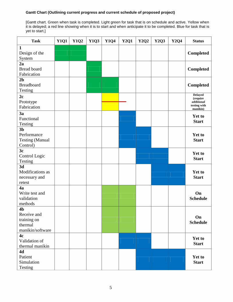
Gantt Chart (Outlining current progress and current schedule of proposed project)
[Gantt chart. Green when task is completed. Light green for task that is on schedule and active. Yellow when it is delayed; a red line showing when it is to start and when anticipate it to be completed. Blue for task that is yet to start.]
Task Y1Q1 Y1Q2 Y1Q3 Y1Q4 Y2Q1 Y2Q2 Y2Q3 Y2Q4 Status
1
Design of the
System Completed
2a
Bread board
Fabrication Completed
2b
Breadboard
Testing Completed
2c
Prototype
Fabrication
Delayed
(require
additional
testing with
manikin)
3a
Functional
Testing
Yet to
Start
3b
Performance
Testing (Manual
Control)
Yet to
Start
3c
Control Logic
Testing
Yet to
Start
3d
Modifications as
necessary and
retest
Yet to
Start
4a
Write test and
validation
methods
On
Schedule
4b
Receive and
training on
thermal
manikin/software
On
Schedule
4c
Validation of
thermal manikin
Yet to
Start
4d
Patient
Simulation
Testing
Yet to
Start

6
Task 1: Design of the System (Months 1 – 6). Completed
Analytical Modeling
As part of Task 1 Design of the System, a commercial software called Modelica/Dymola is being used to develop the prototype analytical model and its cycle components. The model will be used to select components and evaluate performance, size and weight of the system. Modelica is an object-oriented language for modeling of large, complex, and heterogeneous physical systems. It is used for multi-domain modeling in robotics, automotive and aerospace applications involving mechanical, electrical, hydraulic and control subsystems, process oriented applications and generation and distribution of electric power. Models in Modelica are mathematically described by differential, algebraic and discrete equations. No particular variable needs to be solved manually. A Modelica tool will have enough information to decide that automatically. Overview description of main component models in the simulation are shown below, The cycle is shown in Figure 1:
Compressor:
Reciprocating and Scroll compressors
Quasi-steady state approach for calculation of enthalpy change and mass flow
Volumetric and isentropic efficiency are provided either as parameters or by characteristic map or
by polynomials
Mechanical connector for interaction with motor/engine model
Pulsing Thermal Expansion Valve:
Expansion is treated as isenthalpic
Quasi-steady state approach for calculation of mass flow according to IEC 60534-2-1 standard
The flow coefficient is given via an input-connector
Physical behaviour of bulb is modeled using maximum operating temperature MOT and
maximum operating pressure MOP
Heat exchangers:
Cross-counter-flow heat exchangers for evaporator and condenser geometries, and also for heater
core with coolant
Different number of passes and layers are possible
Parametrization features enable more generalized and simplified implementation of new heat
exchangers
Internal refrigerant/refrigerant heat exchanger
Coolant/refrigerant heat exchanger
Accumulator:
High pressure accumulator built up from phase separator, flow resistance and pipe. Low pressure
receiver also built up from fundamental, physically modelledcomponents
7
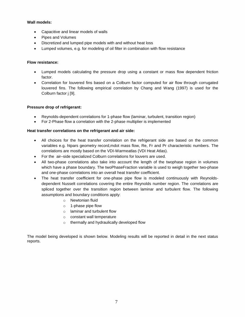
Wall models:
Capacitive and linear models of walls
Pipes and Volumes
Discretized and lumped pipe models with and without heat loss
Lumped volumes, e.g. for modeling of oil filter in combination with flow resistance
Flow resistance:
Lumped models calculating the pressure drop using a constant or mass flow dependent friction
factor.
Correlation for louvered fins based on a Colburn factor computed for air flow through corrugated
louvered fins. The following empirical correlation by Chang and Wang (1997) is used for the
Colburn factor j [9].
Pressure drop of refrigerant:
Reynolds-dependent correlations for 1-phase flow (laminar, turbulent, transition region)
For 2-Phase flow a correlation with the 2-phase multiplier is implemented Heat transfer correlations on the refrigerant and air side:
All choices for the heat transfer correlation on the refrigerant side are based on the common
variables e.g. htpars geometry record,mdot mass flow, Re, Fr and Pr characteristic numbers. The
correlations are mostly based on the VDI-Warmeatlas (VDI Heat Atlas).
For the air–side specialized Colburn correlations for louvers are used.
All two-phase correlations also take into account the length of the twophase region in volumes
which have a phase boundary. The twoPhaseFraction variable is used to weigh together two-phase
and one-phase correlations into an overall heat transfer coefficient.
The heat transfer coefficient for one-phase pipe flow is modeled continuously with Reynolds-
dependent Nusselt correlations covering the entire Reynolds number region. The correlations are
spliced together over the transition region between laminar and turbulent flow. The following
assumptions and boundary conditions apply:
o Newtonian fluid
o 1-phase pipe flow
o laminar and turbulent flow
o constant wall temperature
o thermally and hydraulically developed flow
The model being developed is shown below. Modeling results will be reported in detail in the next status reports.

8
Figure 1. Simulation Model with Modelica components
Refrigerant Selection Another step in developing the system is the selection of the most adequate refrigerant for a given operating condition, observing the theoretical efficiency, necessary refrigerant flow and finally the volumetric displacement required for the compressor. The ambient temperature of 35°C (95°F) and considered refrigeration cycle was that shown in figure 2.
Figure 2. Thermodynamic cycle (Pressure-Enthalpy diagram)

9
In the considered thermodynamic cycle, evaporator enthalpy difference refers only to the useful heat exchanged, with isenthalpic expansion in process 3-4 and saturated vapor in 1’, without overheating in the evaporator and without sub cooling in the condenser. At the beginning of compression, vapor super-heating is considered at an ambient temperature of (25°C). Process 1-2 refers to an isentropic compression. These conditions represent the lowest theoretical isentropic performance and the condition that is the closest to the real application. The cycle performance will be calculated using the simulation model being developed.
Design for Efficiency and Compactness A major obstacle to building compact vapor compression systems has been the absence of commercially available and affordable miniature compressors in the fractional-kilowatt range that would fit within a small space. Recently, such a compressor has been developed and become available that is only 5.6 cm in diameter, 7.6 cm high, and weighs about 600 g. A photograph of the mini-compressor is shown in Figure 3. Figure 4 shows a preliminary layout of the major system components.
Figure 3. Miniature Compressor
Figure 4. Preliminary Layout of System Components

10
Due to space limitations and compact requirements, the design employs other high performance components including custom designed evaporator and condenser heat exchangers. In order to keep the heat transfer surfaces clean from airborne particulates, an air filter can be included in the sealed air system. The reduction in size has a strong correlation with compressor operating frequency for various aspects. The first is fundamental, and refers to the volumetric displacement occurring over a period of time. The greater the frequency the smaller the displaced volume in each compression cycle and, thus, the smaller the compression mechanism dimensions can be. On the other hand, the space available for installing the valves becomes smaller. Thus, the definition of compression pump becomes a simultaneous optimization of the mechanism variables related to the displaced volume and valve system, as an operating frequency function. It is important to note that the volumetric yield is not linear due to operating frequency, as there are other variables such as dead volume and leakage between piston and cylinder which affect it. This calculation considers the re-dimensioning of the valves in order for them to operate adequately at high frequency. The behavior of the volumetric efficiency as a function of the operating frequency is shown in figure 5.
Figure 5. Volumetric efficiency according to running frequency
As part of the design and selection of the vapor compression system different miniature compressors from three different vendors have been studied and analyzed. Three compressors studied are: 1) a rotary compressor manufactured by Engel, and 2) a reciprocating compressor manufactured by Hitachi and 3) Rotary compressor made by Aspen. The Aspen miniature rotary compressor operates with a rolling piston mechanism. It uses a brushless electric motor that runs on 24 V DC power supply. Figure 6 shows the important external dimensions of the compressor, while its specifications are given in Table 1.

11
Table 1. Compressor Specifications
Refrigerant R134a
Lubrication oil Nu Calgon RL68H Polyol ester oil
Compressor type Rotary (rolling piston)
Compressor displacement 1.4 cc
Compressor speed Variable
Speed range 2000 – 6500 RPM
Motor Brushless DC
Voltage 24 V DC
Maximum current 12 Amps continuous
Evaporator temperature range -18 – 24 °C
Condenser temperature range 27 – 71 °C
Maximum discharge temperature 130 °C
Maximum compression ratio 8:1
Figure 6. Aspen Compressor dimensions

12
Measurements and Data Reduction Experimental tests on the compressor are conducted at three different suction pressures, four pressure ratios, and three compressor rotational speeds. The following parameters are directly measured using the instrumentation: 1) Suction pressure and temperature 2) Discharge pressure and temperature 3) Refrigerant mass flow rate 4) Electrical power consumed by the compressor (by measuring DC voltage and current supplied to the main circuit board) 5) Compressor rotational speed (by measuring the DC voltage supplied to the secondary circuit board). Results Table 2 provides a comparison of these compressors. It clearly demonstrates that the sizing of the compressor holds the key to an efficient miniature refrigeration system for electronics cooling. The two compressors tested by Trutassanawin et al. (2006) offered relatively poor performance [10]. The Aspen rotary compressor, however, has a much smaller displacement volume and provides good system performance. Table 2. Compressor Results Comparison
Engel rotary compressor
Hitachi reciprocating compressor
Aspen rotary compressor
Dimensions
Height (mm) 166 195 78
Length/diameter (mm) 85 204 56
Width (mm) - 13 mm -
Displacement (cc) 2.3 2.0 1.4
Weight (kg) 2.8 4.3 0.6
Performance with refrigerant R134a
Pressure ratio 2.1 – 3.2 1.9 – 3.0 2.0 – 3.5
Speed (rpm) 2000 2000 3000 – 6000
Volumetric efficiency (%) 57.0 – 79.3 58.1 – 73.0 73.2 – 90.5
Overall isentropic efficiency (%)
40.6 – 59.5 43.2 – 56.5 44.1 – 70.3
Cooling capacity (W) 130.1 – 256.4 152.2 – 208.8 160.2 – 489.6
System COP 3.0 – 5.7 2.6 – 3.7 2.1 – 7.4
Implementing QSR
The University of Nevada School of Medicine (UNSOM) hired a Food and Drug Administration (FDA) consultant to begin work on implementing a Quality System Regulation (QSR) at Rocky Research and UNSOM, department of Surgery Research Laboratory. The QSR will be ongoing throughout the duration of the project and is required for 510(k) submission and FDA clearance of the medical device. The following QSR Standard Operating Procedures (SOP’s) have been implemented at UNSOM department of Surgery Research Laboratory.
1. “Creation, Format, and Review of SOP’s” – Defines the procedure for the creation, format, and review of SOP’s within UNSOM department of Surgery Research Laboratory
2. “Quality Policy” – Defines overall intentions and direction with respect to quality within UNSOM
department of Surgery Research Laboratory.

13
3. “Management Responsibility and Organization Policy” – Defines UNSOM department of Surgery
Research Laboratory management responsibility, objectives and commitment to quality. 4. “Validation Policy” – Outlines policy for qualification, validation, and calibration of equipment, processes
and systems throughout UNSOM department of Surgery Research Laboratory. 5. “Training” – Procedure of training and training documentation for all UNSOM department of Surgery
Research Laboratory personnel subject to Good Manufacturing Practices (GMP). 6. “Laboratory Entry and Review Guide” – Procedure to provide uniformity in the practice of recording data
and to assure compliance with GMP data recording requirements. 7. “Significant Figures and Rounding” – Establishes convention for rounding of analytical data obtained in
the laboratory or provided to UNSOM department of Surgery Research Laboratory. 8. “Instrument and Equipment Calibration and Maintenance” – Policy and system for instrument calibration
and maintenance. Policy applies to all instruments used in manufacturing, processing, testing, packaging, labeling, and holding of devices with UNSOM department of Surgery Research Laboratory.
9. “Regulatory Inspection Policy” – Define Good Manufacturing Practice (GMP) Inspections Policy for
Regulatory Agencies visiting UNSOM department of Surgery Research Laboratory. 10. “Issuance and Control of Notebooks/Logbooks” – Procedure for issuance and control of hardbound
notebooks including logbooks and laboratory notebooks at UNSOM department of Surgery Research Laboratory.
11. “Corrective and Preventive Actions (CAPA) – Provide a procedure and system by which CAPA can be
initiated, documented, and completed for UNSOM department of Surgery Research Laboratory. 12. “Change Control” – Procedure for initiation, review, approval, implementation, and documentation of
changes made to Specifications, Procedures, Protocols, Validations and any GMP documentation or equipment that may impact a regulatory submission or the identity, strength, quality and purity of a product at UNSOM department of Surgery Research Laboratory.
13. “Investigating Out of Specification (OOS) Test Results” – Procedure for providing guidance for
investigating OOS GMP test results at UNSOM department of Surgery Research Laboratory. 14. “Records Retention Policy” – Defines UNSOM department of Surgery Research Laboratory record
retention policy for production, control and distribution of documents and reports. 15. “Qualification of Vendors & Contract Facilities” – Provide a standardized procedure, requirements and
responsibilities for qualification and continued certification of vendors and contract facilities at UNSOM department of Surgery Research Laboratory.
16. “Internal Audits” – Provide a system of self-assessment through randomly scheduled internal audits at
regular intervals at UNSOM department of Surgery Research Laboratory.
17. “Corrective and Preventive Actions (CAPA)” – Provide a procedure and system by which CAPA can be initiated, documented, and completed for UNSOM department of Surgery Research Laboratory. 18. “Change Control” – Procedure for initiation, review, approval, implementation, and documentation of changes made to Specifications, Procedures, Protocols, Validations and any GMP documentation or equipment that may impact a regulatory submission or the identity, strength, quality and purity of a product at UNSOM department of Surgery Research Laboratory. 19. “Investigating Out of Specification (OOS) Test Results” – Procedure for providing guidance for investigating OOS GMP test results at UNSOM department of Surgery Research Laboratory.

14
20. “Records Retention Policy” – Defines UNSOM department of Surgery Research Laboratory record retention policy for production, control and distribution of documents and reports. 21. “Qualification of Vendors & Contract Facilities” – Provide a standardized procedure, requirements and responsibilities for qualification and continued certification of vendors and contract facilities at UNSOM department of Surgery Research Laboratory. 22. “Internal Audits” – Provide a system of self-assessment through randomly scheduled internal audits at regular intervals at UNSOM department of Surgery Research Laboratory. 23. “Personal Hygiene” – Provide a procedure and instruction in personal hygiene for all UNSOM personnel subject to Good Manufacturing Practices (GMP). 24. “Central Documentation” – Procedure to determine which documents should be retained in Central Documentation and the retention period for various types of documents. Teleconference with Military Experts During Y1Q3 UNSOM and Rocky Research held two teleconferences with military experts and answered questions regarding Commercial off-the-shelf (COTS) blankets to be tested, the user interface of the device, temperature sensors, typical use with regards to military applications, and the control algorithm. Additional information was requested by the working group during Y1Q4 regarding a diagram illustrating the interaction of the body temperature conditioning system with the patient and clinical scenarios in which this system could be utilized. See Appendix A: Notes from May 17, 2012 Teleconference with University of Nevada, Reno Portable Body Temperature Conditioner
Task 2: Prototype Fabrication (Months 7-12). In Progress
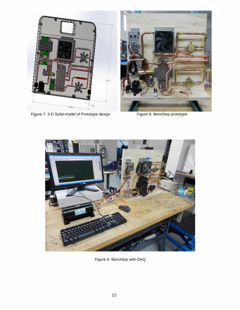
2a. Breadboard design and Fabrication
The breadboard design is very similar to the prototype design as shown in figure1. The exception is that the breadboard is designed such that components can be changed as needed with ease. Since the component changes requires the connections not to be all soldered and as such quick connect and disconnects are used in the breadboard where in the packaged prototype these will be replaced with continous tubing and solder joints. Figures 7-9 show the completed benchtop with the Data acquisition system. The instrumentations measured all relevant temperature and pressure statepoints in addition to cooling capacity and power consumtion. All the data are logged for further analysis.
15
Figure 7. 3-D Solid-model of Prototype design Figure 8. Benchtop prototype
Figure 9. Benchtop with DAQ

16
2b. Breadboard Test Results Compressor selection was a primary focus of breadboard testing. Complete test matrices have been constructed and evaluated for each of the compressors under consideration. The test matrices are extensive because each compressor was analyzed at varying compressor speeds under different heating and cooling conditions. Tables 3, 4, and 5 depict the test matrices for the Aspen, Danfoss, and Sawafuji compressors, respectively. Cooling modes were tested for bath temperatures of 20 °C, 10 °C, and 5 °C while heating performance was evaluated with bath temperatures of 42 °C and 40 °C. Voltage was maintained constant for each test at 25.2v. The coefficient of performance (COP) was calculated for each compressor under each heating and cooling assessment to evaluate overall compressor performance. The performance of each compressor was then compared and contrasted in terms of capacity, efficiency, and feasibility while considering size and weight parameters. It is important to distinguish that all compressor testing was performed open loop, with a bath simulating the load. The selected compressor will have to be re-analyzed with loading from the thermal manikin before being implemented in the final prototype. Table 3. Complete Test matrix for Aspen Compressor

17
Table 4. Complete Test matrix for Danfoss Compressor
Table 5. Complete Test matrix for Sawafuji Compressor
Upon completion of the compressor test matrices several observations were realized. The Sawafuji swing motor compressor did not allow for the variance of motor speed. Resultantly, the compressor demonstrated poor performance as depicted by the COP in table 5, particularly for the heating mode tests. Consequently, the Sawafuji compressor was immediately eliminated as a viable option for prototype fabrication.
18
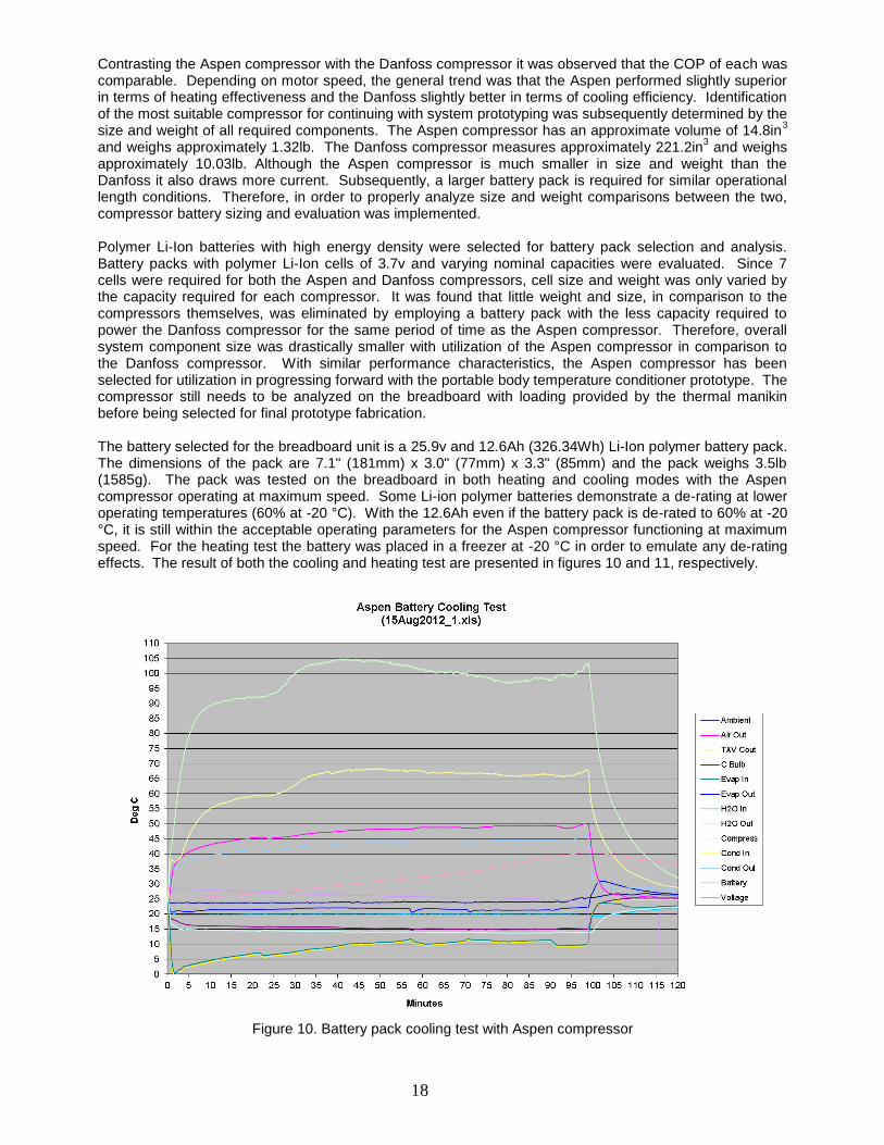
Contrasting the Aspen compressor with the Danfoss compressor it was observed that the COP of each was comparable. Depending on motor speed, the general trend was that the Aspen performed slightly superior in terms of heating effectiveness and the Danfoss slightly better in terms of cooling efficiency. Identification of the most suitable compressor for continuing with system prototyping was subsequently determined by the size and weight of all required components. The Aspen compressor has an approximate volume of 14.8in
3
and weighs approximately 1.32lb. The Danfoss compressor measures approximately 221.2in3 and weighs
approximately 10.03lb. Although the Aspen compressor is much smaller in size and weight than the Danfoss it also draws more current. Subsequently, a larger battery pack is required for similar operational length conditions. Therefore, in order to properly analyze size and weight comparisons between the two, compressor battery sizing and evaluation was implemented. Polymer Li-Ion batteries with high energy density were selected for battery pack selection and analysis. Battery packs with polymer Li-Ion cells of 3.7v and varying nominal capacities were evaluated. Since 7 cells were required for both the Aspen and Danfoss compressors, cell size and weight was only varied by the capacity required for each compressor. It was found that little weight and size, in comparison to the compressors themselves, was eliminated by employing a battery pack with the less capacity required to power the Danfoss compressor for the same period of time as the Aspen compressor. Therefore, overall system component size was drastically smaller with utilization of the Aspen compressor in comparison to the Danfoss compressor. With similar performance characteristics, the Aspen compressor has been selected for utilization in progressing forward with the portable body temperature conditioner prototype. The compressor still needs to be analyzed on the breadboard with loading provided by the thermal manikin before being selected for final prototype fabrication. The battery selected for the breadboard unit is a 25.9v and 12.6Ah (326.34Wh) Li-Ion polymer battery pack. The dimensions of the pack are 7.1" (181mm) x 3.0" (77mm) x 3.3" (85mm) and the pack weighs 3.5lb (1585g). The pack was tested on the breadboard in both heating and cooling modes with the Aspen compressor operating at maximum speed. Some Li-ion polymer batteries demonstrate a de-rating at lower operating temperatures (60% at -20 °C). With the 12.6Ah even if the battery pack is de-rated to 60% at -20 °C, it is still within the acceptable operating parameters for the Aspen compressor functioning at maximum speed. For the heating test the battery was placed in a freezer at -20 °C in order to emulate any de-rating effects. The result of both the cooling and heating test are presented in figures 10 and 11, respectively.
Figure 10. Battery pack cooling test with Aspen compressor

19
Figure 11. Battery pack heating test with Aspen compressor
As can be observed, the battery pack was able to adequately supply power to all of the breadboard components for 100 minutes in cooling mode and 110 minutes in heating mode. Consequently, the battery pack was verified as a sufficient selection for progressing forward with the portable body temperature conditioner prototype. A battery charger and power supply have also been selected for the unit. The smart charger has a standard charging rate of 6.0A, capable of recharging the entire battery pack in approximately 3.15 hours. The power supply is a high efficiency, low profile, component with full digital control and high peak loading capability. Both components have been tested on the breadboard. The charger and power supply are packaged separately from the portable body temperature conditioner unit as a detachable external component. Such an approach allows for the unit to retain its minimalistic characteristics in terms of weight and size. Figure 12 presents a drawing of the unit along with the packaged external power supply and charger. The dimensions have been specified on the drawing in inches.
Figure 12. Prototype design with externally packaged power supply and charger unit

20
Two pumps have been investigated for utilization in the portable body temperature conditioner unit. A 24v centrifugal pump with dimensions of 3.75" L x 3" W x 3" H and a maximum flow rate of 1.1gpm has been initially selected. The other pump under consideration was a small micro pump with 0.57" D x 2.5" L. Although the micro pump was optimal in terms of size, after extensive testing, it was concluded that the pump did not provide adequate capability in maintaining flow rates. Furthermore, the micro pump was relatively noisy and raised concerns in terms of reliability. Open loop testing of the selected centrifugal pump through the entire system loop, including hyper-hypothermia blanket, revealed the pump was able to maintain a flow rate of approximately 0.5gpm with 1ft of pressure head.
A hyper-hypothermia blanket has been selected for utilization in evaluating performance of the portable body temperature conditioner unit. The blanket has been obtained along with the required connection hose. The blanket utilized for system performance analysis is a Cincinnati Sub-Zero adult sized Maxi-Therm
®
blanket measuring 60" L x 24" W. Proper quick connect hydraulic couplings have been acquired and fitted to the plumbing of the breadboard unit to allow connection of the portable conditioner to the blanket via the 9ʹ connection hose. Flow has been analyzed through the blanket and weight measurements of full and empty blankets, as well as connection hoses, have been taken in order to quantify water content. It was found that at ambient conditions (25 °C) the blanket and hose contain approximately 15.6L (95in
3) of water
during operation, a crucial quantification in designing for system filling procedures.
2c. Prototype Fabrication
The prototype design for the portable body temperature conditioner has been refined based on the results of breadboard component testing. A drawing of the new design, with all of the currently identified components, is presented in figure 13. The drawing also depicts necessary mounting hardware. Prototype fabrication has not yet begun since the breadboard still needs to be evaluated with a load provided by the thermal manikin. Logically, comprehensive testing on the breadboard utilizing the thermal manikin should be implemented before prototype fabrication. Such an approach allows for the components to be thoroughly evaluated before final selection. The portable body temperature conditioner unit is depicted in figure 14 along with the external power supply, connection hose, thermal manikin, and hyper-hypothermia blanket. The orientation of the drawing in figure 14 is such that the thermal manikin is lying on its back. Once the thermal manikin is obtained completion of breadboard testing will ensue, and final component selection for prototype fabrications will be implemented.
Figure 13. Internal prototype design perspective with intended selected components

21
Figure 14. Aerial view of conditioner, connection hose, power supply, blanket, and thermal manikin
Task 3: Prototype Testing (Months 12-24). Yet to start (Task 3 set to begin upon completion of Task 2, within the first quarter of year 2)
a. Functional testing. Yet to start
b. Performance testing (manual control). Yet to start
c. Control logic testing. Yet to start
d. Modifications as necessary and retest. Yet to start
Task 4: Patient Load Simulation Testing (Months 9 – 24). In Progress
Write test and validation methods
UNSOM has begun determining standard testing metrics to be used during the patient simulation testing. These metrics include; temperature limits of the convective fluid, allowable patient core temperature range, ranges of hypo-hyperthermia, and temperature/heat flux conditions.
Receive and training on thermal manikin/software
The thermal manikin “Newton” was purchased from Measurement Technology Northwest (MTNW), which is a Seattle based company specializing in the manufacture of thermal manikins and associated accessories. The manikin was originally scheduled to be delivered at the end of August; however there was a slight delay in fabrication by MTNW. Fabrication of the manikin was completed and shipped from MTNW on 07-Sep-2012. UNSOM received the thermal manikin and associated accessories on 11-Sep-2012.

22
Training personnel from Measurement Technology Northwest (MTNW) were scheduled to come for two days from September 26-27, 2012. Included with the training session, MTNW personnel are expected to assemble and test the thermal manikin “Newton” and the associated accessories. Additionally, MTNW personnel are going to train UNSOM and pertinent Rocky Research staff on the general use and maintenance of the thermal manikin “Newton”.
Validation of the thermal manikin
Measurement technology Northwest will perform parts of the validation procedures for installation qualification (IQ) and operational qualification (OQ) when they come for the assembly-training session for the thermal manikin. Additionally, MTNW will train UNSOM and Rocky Research personnel on how to do performance checks/calibration during routine maintenance, which will encompass performance qualification (PQ).
KEY RESEARCH ACCOMPLISHMENTS:
The Following were accomplished in the past year:
System Design: The vapor compression system used in the prototype was modeled, performance was predicted and components selected.
Breadboard Prototype Fabrication: The prototype was assembled on a laboratory breadboard. The size and dimension of the overall breadboard is kept exactly the same as the final prototype.
Breadboard Prototype testing: The prototype testing was completed and components were selected based on the performance results.
Prototype Drawings: The drawings for the final prototype were completed and refined during testing. These engineering drawings will be used for future fabrication and cost analysis.
The system performance on cooling and heating capacity and COP are shown in Table 3. The cooling capacity was measure to be between 200 to 400 Watts at COPs of greater than 1.5. The heating Performance was between 200 to 300 Watts at COPs of greater than 1.7.
The prototype was successfully tested using DC generated from high power density Lithium-Polymer batteries and 110VAC power.
Patient Simulation Testing: The thermal manikin was purchased and received from Measurement Technology Northwest on 11-Sep-2012. Also, a training-installation session was scheduled for September 26-27, 2012 to introduce UNSOM and select Rocky Research personnel to the general use and maintenance of the thermal manikin and associated software.
Implementing QSR: Currently, 24 Standard Operating Procedures (SOP’s) have been implemented for UNSOM’s quality systems. Rocky Research began implementing SOP’s in March 2012 and continues to implement approximately 2 – 5 SOP’s per quarter. UNSOM continues to work with a FDA consultant as part of QSR compliance.
REPORTABLE OUTCOMES:
Currently, the project is still in the design/fabrication phase of the prototype and testing of the device has not yet begun. As such, no abstracts, presentations, publications or other equivalent reportable outcomes have been produced from this research at this time.
CONCLUSION:
The prototype breadboard for portable body temperature conditioner has been successfully designed, fabricated, and tested. The test results show that the prototype meets the overall capacity and efficiency requirements. The prototype was further tested using both AC and DC power sources thus demonstrating the power versatility feature. The DC power operation lasted more than 1 hour exceeding the initial design goal. Also, a water-circulating blanket was purchased and integrated with the prototype. A custom thermal-

23
manikin was purchased and received from Measurement Technology Northwest on 11-September-2012. Additionally, a training-installation session was scheduled with MTNW for the 26-27-Sep-2012. Installation and operation qualification will be completed during the scheduled training session with MTNW as part of the validation procedure. Further testing of the prototype, water-circulating blanket, and the thermal-manikin is required to reveal necessary refinements in the prototype. Once these refinements are made a complete prototype will then be assembled and tested. Additionally, quality system regulations are currently being implemented by both UNSOM and Rocky Research as part of a working goal toward FDA medical device clearance and 510(k) submission.
Defense medical installations require efficient and reliable equipment for the thermoregulation of either injured or ill patients. However, effective methods for warming/cooling injured patients during medical evacuations in the absence of a reliable power source are currently unavailable. The current research will yield a portable, reliable, intuitive device that will effectively maintain normal core body temperature during transport between various levels of combat casualty care. Similarly, the portable body temperature conditioner will also translate to civilian use as an essential tool for Emergency Medical Service (EMS) crews in response to emergency situations within the general public.
AWARD PARTICIPANTS:
The number of individuals participating on this project and receiving salary support from this USAMRAA award during this reporting period is listed below.
Organization Number of Supported Staff
UNSOM 3
Med-School Associates South 2
Rocky Research 5
Total Number Supported Staff 10
REFERENCES:
[1] Aragon D. Temperature management in trauma patients across the continuum of care: the TEMP Group. Temperature Evaluation and Management Project. AACN Clin Issues 1999 Feb; 10(1):113-23.
[2] Bernabel AF, Levison MA, Bender JS. The effects of hypothermia and injury severity on blood loss during trauma laparotomy. J Trauma 1992;33:835-9.
[3] Fritsch DE. Hypothermia in the trauma patient. AACN Clin Issues 1995 May;6(2):196-211.
[4] Gregory JS, Flancbau L, Townsend MC, et al. Incidence and timing of hypothermia in trauma patients undergoing operations, J Trauma 1991;31:795-8.
[5] Jurkovich GJ, Greiser WB, Luteman A, et al. Hypothermia in trauma victims: an ominous predictor of survival. J Trauma 1987;27:1019-24.
[6] Tsuei BJ, Kearney PA. Hypothermia in the trauma patient. Injury, Int. J Care Injured 2004;35:7-15.
[7] Sinclair W, Rudzki S, Leicht A, et al. Efficacy of field treatments to reduce body core temperature in hyperthermia subjects. Medicine and Science in Sports and Exercise 2009 March; 1984-1990.
[8] Smalley B, Janke R, and Cole D. Exertional heat illness in Air Force basic military trainees. Military Medicine 2003;4: 298-303.

24
[9] Chang, Y.J. and Wang, C.C. (1997). A Generalized Heat Transfer Correlation for Louver Fin Geometry, Int. J. Heat Mass Transfer, Vol. 40(3), pp.533-544.
[10] Trutassanawin, S., Groll, E. A., Garimella, S. V. and Cremaschi, L., 2006, “Experimental investigation of a miniature-scale refrigeration system for electronics cooling,” IEEE Transaction on Components and Packaging Technologies, Vol. 29, No. 3, pp. 678-687.
APPENDICES / SUPPORTING DATA:
Appendix A:
Notes from May 17, 2012 Teleconference with University of Nevada, Reno
Portable Body Temperature Conditioner
General Questions The main goal in the development of the portable body temperature conditioner is core temperature maintenance as to prevent further temperature loss. It may be difficult to raise a patient’s core temperature in the field due to non-ideal conditions and the patient’s injuries. The advantages of the proposed system is that it will provide sufficient heating and cooling power to maintain normothermia under typical conditions encountered in the field and during air transport.
1. Clinical utility in austere environments where ice packs are not available.
To promote use in austere environments, the device will be lightweight, of minimal size, and battery
operated allowing for maximum portability.
2. Does design address MilSpecs and when will you test device for meeting MilSpecs?
Phase I Technical Objectives
The major technical objectives of the proposed project are to design, develop, fabricate, and test a portable body temperature conditioner subject to extreme ambient conditions to determine performance and cost. In order to reach realistic results a compressor breadboard suitable to measure energy consumption and evaluate the feasibility and practicality of the concept will be fabricated and used. The data generated in the compressor breadboard will be used in the design. Based on the compressor and heat exchanger selection a 3-D solid model of the system will be generated using SolidWorks. A prototype will then be fabricated and tested with and without simulated patient body heat loads. Sub-objectives are:
1. The development of an analytical model of the system 2. The design of the prototype 3. SolidWorks 3-D modeling and drawings 4. The fabrication of the prototype 5. Testing of the prototype on the workbench 6. Testing of the prototype with the patient simulated load 7. Preliminary cost analysis 8. Begin implementing design and quality regulatory controls required by Food and Drug Administration
(FDA)
Military Standards
The system will be designed to operate in harsh military environments including airborne, shipboard, and ground mobile conditions. The device will be designed to meet military standards in current phase but not tested for meeting military standards until fabrication of the prototype has been completed. This is scheduled to occur in phase 3 of the project. The specific Mil-Standards that the system will be designed to pass in the upcoming phase are:

25
Environmental
MIL-STD-810G-507.4 HUMIDITY
MIL-STD-810G-509.4 SALT/FOG
MIL-STD-810G-510.4SAND/DUST
MIL-STD-810G-500.4 LOW PRESSURE(ALTITUDE) PROCEDURE II
MIL-STD-810G-501.4 HIGH TEMPERATURE PROCEDURE I
MIL-STD-810G-501.4 HIGH TEMPERATURE PROCEDURE II
MIL-STD-810G-502.4 LOW TEMPERATURE PROCEDURE II
MIL-STD-810G-514.5 VIBRATION
MIL-STD-810G-516.5MECHANICAL SHOCK, PROCEDURE
EMI (The following Mil-Standards apply to Air –worthiness in addition to mobile systems on the ground)
MIL-STD 461E,FCE 102 CONDUCTED EMISSIONS, POWER LEADS
MIL-STD 461E,FCS 10 CONDUCTED SUSCEPTIBILITY, POWER LEADS
MIL-STD 461E,FRE 102 RADIATED EMISSIONS
MIL-STD 461E,FRS 103RADIATED SUSCEPTIBILITY
3. How does system interact with casualty? (Provide diagram of the whole system with casualty)
The device will be able to interface with a typical core temperature measuring probe, allowing for a direct feedback control system based on the patient’s core body temperature. In automatic or gradient temperature mode, the device will provide heating or cooling based on the patient’s current core temperature, circulating the appropriate temperature fluid through the convective/conductive blanket. A simple diagram of the interface between the patient and the temperature conditioning device is provided in figure 1. The body temperature conditioning system is connected to the convective blanket with an inlet and exit flow setup. This allows the heated or cooled convective fluid to flow into the blanket, circulate, and then exit back into the temperature conditioning device. The user interface is a generalized schematic and is planned to incorporate a user interface similar to commercial conditioning blanket systems. A simple flow chart describing the interaction between the patient and temperature conditioning device is in gradient or automatic mode is provided in figure 2.
In just about every scenario where this device would be used the patient will need to be intubated and sedated, as the systems primary function is to maintain core body temperature or warm/cool the patient as part of a resuscitative effort during transport to improve the patient’s outcome.
In a cardiac arrest scenario where the idea is to cool the patient and prevent brain injury the patient will need to be intubated and sedated to tolerate cooling. Most patients put into iatrogenic hypothermia will shiver, experience pain, and on a whole be really uncomfortable. If they are sufficiently obtunded to require this therapy then they almost certainly will require intubation. Cooling of a patient is not recommended unless the patient requires intubation and an invasive temperature monitoring probe is required.
Clinical Scenario
A 24 year old male suffers blast wounds to the right upper extremity and torso with 10% total body surface area burns to the chest. The ambient temperature is 22
o C. A first responder arrives and upon removing the burned
clothing and exposing the areas of injury, severe mangling of the extremity is noted. The patient is moved to a safe location where it is determined his airway is patent, he is breathing without issues and he has palpable pulses in all extremities save the mangled arm. The transport team arrives and IV access is placed in the unaffected limb and room temperature fluids are initiated. The patient is tachycardic and anxious, his blood pressure is normal, skin temperature is 36.0
o C. The patient complains of severe abdominal pain and intra-abdominal injury is suspected.
In this scenario the patient is already in the early stages of shock. He is also mildly hypothermic. In a scenario such as this where the ambient temperature is 22
o C, the patient is burned, and the patient has had
significant blood loss - the patient warmer would be applied with the arrival of transport utilizing a skin temperature probe. In this situation, the body temperature conditioning device is primarily being used for body temperature maintenance, as to prevent any further heat loss. This, in addition to resuscitation would prevent worsening of the

26
hypothermia and subsequent coagulopathy. An invasive core temperature monitor could be placed should the patient require intubation or additional invasive monitoring. In burned patients heat loss can occur quickly. Lastly, this patient may require urgent operative intervention. Acidosis and coagulopathy can be prevented by addressing the issue of heat loss via blanket technology rather than "playing catch-up" in the OR.
Figure 1. Diagram of body temperature conditioning system interaction with patient.

27
Figure 2. Simple flow chart describing the interface between patient and temperature conditioning device.

28
4. How are adjustments made to not allow patient to get too hot or too cold?
With respect to patient safety and ease of operation, the device will have several safety applications built
in. To prevent the patient from being over heated or cooled, the device will have upper and lower limits
of temperature, control systems, automatic shut-off when the temperature exceeds set points, and an
alarm system to notify the operator of dangerous temperature situations.
5. Can the system be used by a medic or nurse and who will use this device?
The device will provide a user friendly interface displaying the following essential patient care data;
patient core temperature, water temperature, and the system status which indicates the temperature set
point and any necessary corrections to be made by the operator. The system will be designed with
intuitive controls to promote ease of use with medics up to physicians. The system will have an
automatic and manual control option for basic temperature management use and a more controlled use
by physicians. The portability of the device will allow its use in the field, during airborne evacuation, and
within a traditional hospital setting.
6. What is your business plan?
Working with medical device manufacturers. We are currently having discussions with Cincinnati Sub-
Zero (CSZ) as a possible consultant on this project. CSZ is a company in the medical temperature
management market. This is an established company with various products related to Hyper-
Hypothermia systems.
7. How much will it cost?
Rocky Research will complete a cost estimate at the end of the current phase when the first prototype is
fabricated and tested. At this time there are too many unknown factors associated with parts, blankets,
and the overall fabrication of the prototype to estimate the cost of the device.
Blanket questions
1. Clarification on blanket(s) to be tested.
CSZ manufactures blankets for hyper-hypothermia systems. If CSZ becomes a consultant on this
project then we can test their blankets on the device. If not, then we will evaluate other commercial off-
the-shelf (COTS) blankets.
2. Will the blanket be sold as part of the device?
The blanket may be sold as part of the device, but should also be available as a standalone product.
Single use or multiple use blankets may be sold, depending on what would be most convenient for the
military.
3. Will recommendations be made?
Based on patient simulation testing, recommendations will be made as to the various types of blankets
to be used with the system. (ie. Pads, whole body blankets, smaller blankets placed in specific locations
on the patient, head wraps, etc.). As well as preferences may be requested by military experts.
4. Will design recommendations/changes be made to manufacturer when tests show that COTS blankets are
not sufficient?
Yes, recommendations may be made to develop and custom blankets specific to our needs.
5. What is price of recommended COTS blankets?
The prices for the various blankets manufactured by Cincinnati Sub-Zero are given in table 1.

29
Table 1: List prices for various blankets manufacture by Cincinnati Sub-Zero
Type Model Size Quantity Cost
Convective hyper-
hypothermia
water
blankets/wraps
Single-Use
Blanket Maxi-Therm
Adult Box 5 $127.00
Pediatric Box 5 $90.00
Infant Box 5 $72.00
Reusable
Blanket Plasti-Pad
Adult Each $193.00
Pediatric Each $157.00
Infant Each $129.00
Reusable
Mattress/Pad Gelli-Roll
Adult Each $1,420.00
Pediatric Each $1,180.00
Infant Each $861.00
Single-Use
Wrap for
brain cooling
Head Wrap One Size Box 10 $2,080.00
Accessories Connection
Hose
Compatible All
Models N/A Each $63.00
Temperature Sensor Questions
1. What temperature sensors/probes and placement to be used? (Correlation to core temperature)
Most commercially available hyper-hypothermia devices currently on the market are able to
accommodate multiple temperature sensor probes. The three main temperature probes used are rectal,
esophageal, and urethral Foley catheter.
The accuracy of a temperature probe can vary depending on the condition and injuries of the patient.
Having multiple options of temperature probes is essential for measuring an accurate core body
temperature.
2. Interval of temperature measurement?
The Blanketrol III from Cincinnati Sub-Zero is able to measure and update the temperature reading on
the user display every 5 seconds. The newest version of this system can also come with data logger
software which can capture data at the following user chosen rates (30 seconds, 1 minute, 5 minutes, 15
minutes, 30 minutes or 60 minutes). This capability would be built into the system being designed by
Rocky Research.
3. Will the sensor be sold as part of the device?
The temperature sensor will likely be sold with the device, but should also be sold separately as an
accessory. The temperature sensor may also be sold in disposable or reusable models.
4. What is price of recommended sensors?
Cincinnati Sub-Zero sells disposable and reusable temperature probes. The temperature probes are
sold in units of 20 and range in price from $93.00 to $158.00. A reusable cable which interfaces with the
temperature probe and hyper-hypothermia system is also sold. The cables range in price from $45.00 to
$48.00. A port would be built into the system being designed by Rocky Research to interface with the
temperature probe.
5. The Working Group made it clear that any device to be considered needs to be non-invasive. Would the
temperature probes you suggested make this a more invasive device or are these probes already used to
monitor the patient without the warming/cooling device?

30
The three main temperature probes (invasive) currently used on the market for hyper-hypothermia
devices are rectal, esophageal and the foley catheter. Other non-invasive probes (skin temperature
probe) may also be used to interface with the device, though they may not be as accurate in measuring
core body temperature. Skin temperature probes are traditionally not as accurate as rectal, esophageal,
or foley catheters (generally inaccurate to a degree greater than 1oC), and are prone to loss of adhesion.
In a trauma scenario where heating is desired (prevention of the lethal triad), an accurate core
temperature reading is crucial for the function of the body temperature conditioning device. However, in
situations where more advanced care is not available the skin temperature probe may be useful for basic
preliminary data collection or activation of the system. Once more advanced care becomes available,
invasive temperature monitoring should be the preferred method for measuring body temperature. It may
be recommended that both types of temperature probes (invasive/non-invasive) be carried as basic
accessories for this device.
Prototype Questions
1. Where is User Interface and what information needs to be displayed?
The user interface will be similar to existing normothermia systems (figure 3), and will offer simple
programmable body temperature regulation. The system will have both an automatic and manual control
setting to enable the operator or physician to have control over the patients care. The user interface will
display the common patient care information typically found in current commercially available patient
warming devices. This includes the following; patient core temperature, water temperature, and the
system status which indicates the temperature set point and any necessary corrections to be made by
the operator.
Figure 3. Example of generalized schematic of graphical user interface
31
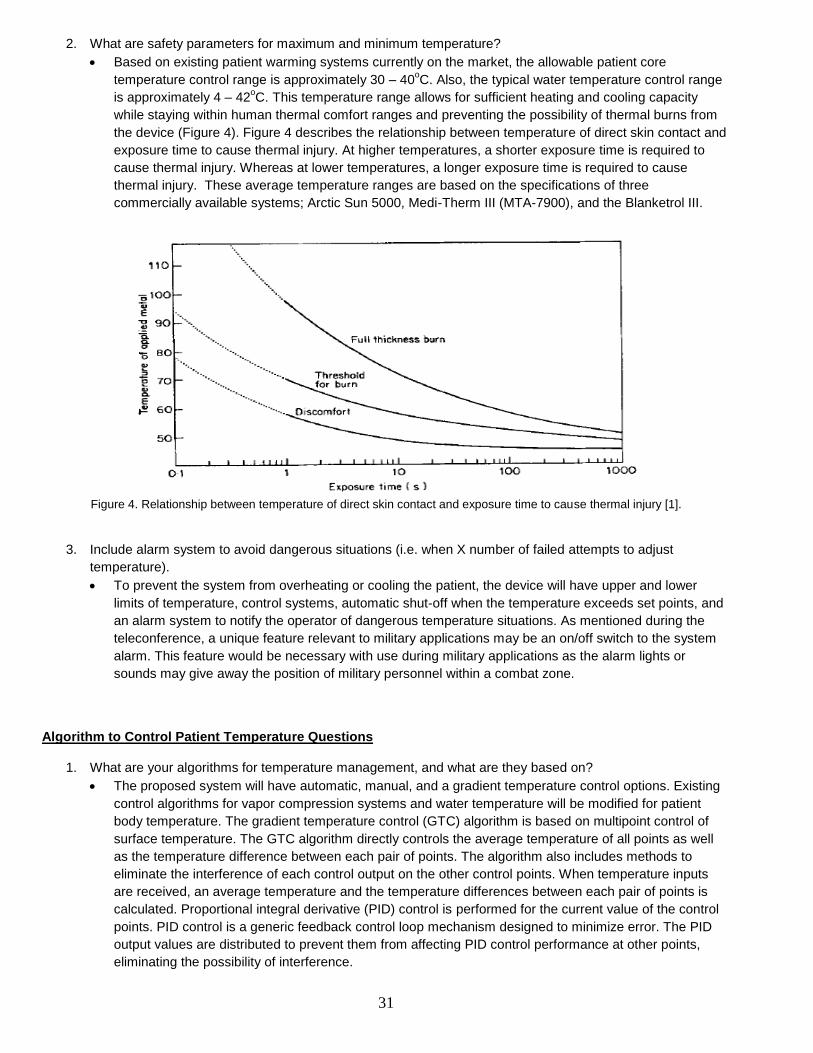
2. What are safety parameters for maximum and minimum temperature?
Based on existing patient warming systems currently on the market, the allowable patient core
temperature control range is approximately 30 – 40oC. Also, the typical water temperature control range
is approximately 4 – 42oC. This temperature range allows for sufficient heating and cooling capacity
while staying within human thermal comfort ranges and preventing the possibility of thermal burns from
the device (Figure 4). Figure 4 describes the relationship between temperature of direct skin contact and
exposure time to cause thermal injury. At higher temperatures, a shorter exposure time is required to
cause thermal injury. Whereas at lower temperatures, a longer exposure time is required to cause
thermal injury. These average temperature ranges are based on the specifications of three
commercially available systems; Arctic Sun 5000, Medi-Therm III (MTA-7900), and the Blanketrol III.
Figure 4. Relationship between temperature of direct skin contact and exposure time to cause thermal injury [1].
3. Include alarm system to avoid dangerous situations (i.e. when X number of failed attempts to adjust
temperature).
To prevent the system from overheating or cooling the patient, the device will have upper and lower
limits of temperature, control systems, automatic shut-off when the temperature exceeds set points, and
an alarm system to notify the operator of dangerous temperature situations. As mentioned during the
teleconference, a unique feature relevant to military applications may be an on/off switch to the system
alarm. This feature would be necessary with use during military applications as the alarm lights or
sounds may give away the position of military personnel within a combat zone.
Algorithm to Control Patient Temperature Questions
1. What are your algorithms for temperature management, and what are they based on?
The proposed system will have automatic, manual, and a gradient temperature control options. Existing
control algorithms for vapor compression systems and water temperature will be modified for patient
body temperature. The gradient temperature control (GTC) algorithm is based on multipoint control of
surface temperature. The GTC algorithm directly controls the average temperature of all points as well
as the temperature difference between each pair of points. The algorithm also includes methods to
eliminate the interference of each control output on the other control points. When temperature inputs
are received, an average temperature and the temperature differences between each pair of points is
calculated. Proportional integral derivative (PID) control is performed for the current value of the control
points. PID control is a generic feedback control loop mechanism designed to minimize error. The PID
output values are distributed to prevent them from affecting PID control performance at other points,
eliminating the possibility of interference.

32
2. To initiate use, do you plan to allow the user to prompt rapid cooling or heating verses temperature
maintenance? (Thus reducing lag time to let the system figure out what is needed).
There will be gradient temperature control in addition to auto and manual options
3. For rapid cooling or heating, what is the desired rate a first responder would hope to achieve with standard
techniques, and what can the system do within its designed safety range for energy (heat) flux?
In terms of rapid heating or cooling, the thermal expansion valve (TXV) designed by Rocky Research
allows for variable speed system operation of the vapor compression system over a wide range of
capacities without damage to the compressor. This allows for the system to reach its maximum cooling
or heating value within a short period of time. However, the overall design of the device is mainly to
control patient temperature and not specifically the water temperature. Also, the system is designed
primarily for temperature management and may not be suitable for rapid heating or cooling of the patient
as the conditions and patients injuries may not be feasible.
4. What are safety parameters for maximum and minimum temperature and how do you plan to incorporate this
in the algorithm?
As mentioned above, the safety parameters for temperature will be based on existing patient warming
systems currently on the market; the allowable patient core temperature control range is approximately
30 – 40oC. Also, the typical water temperature control range is approximately 4 – 42
oC. Safety
parameters will be included within both the logic control and in the hardware where if one fails the
redundant system ensures that there is no over/under shoot of patient temperature.
5. What are your safety parameters for maximum heat flux across the system in contact with the patient, and
how do you plan to incorporate this in the algorithm?
The relationship between heat flux and exposure time to cause thermal injury is described in figure 5.
Safety parameters for maximum heat flux between the system and patient will be based on this data. At
higher heat flux densities, a shorter exposure time is required to cause thermal injury. Whereas at lower
heat flux densities, a longer exposure time is required to cause thermal injury. However, this data is
based on skin contact with a heat metal plate and will need to be further evaluated during the patient
simulation testing.

33
Figure 5. Relationship between heat flux and exposure time to cause thermal injury [1]
6. Will you monitor and display trends (i.e. patient has been steadily losing temperature as x degrees / minute)?
Yes, to be determined.
7. If the system notices it cannot compensate for patients temperature changes, how will the system notify the
user?
The user interface will include a gradient variable button/function which activates the gradient variable
mode. The gradient variable mode operation is based on the temperature of the patient relative to the
set point temperature. The difference between the set-point and patient core body temperature will be
reported. This accounts for situations in which the system is unable to compensate for the patient’s
temperature changes.
References: [1] Bull, J.P., Lawrence, J.C., Thermal conditions to produce skin burns. Fire and Materials. 3: 100-105, 1979.