ad-ao15 705 army communications … · · 2014-09-27ad-ao15 705 army communications ... spread...
TRANSCRIPT

AD-AO15 705 ARMY COMMUNICATIONS-ELECTRONICS COMMAND FORT MONMOUTH N.J F/G 17/R
ELECTROMAGNETIC COUNTER-COUNTER MEASURE (ECCM) TECHNIQUES OF TH--ETC(U)MAY 82 J E BARTOW
UNCLASSIFIED CECOM-82-3 NL
A D-AI1705 ARMNIl
LF
0Eu0...U....?

RESEARCH AND DEVELOPMENT TECHNICAL REPORTCECOIM - 82-3
ELECTROMAGNETIC COUNTER-COUNTER MEASURE (ECCM)
9l TECHNIQUES OF THE DIGITAL MICROWAVE RADIO
l i JAMES E. BARTOW
S CENTER FOR COMMUNICATIONS SYSTEMS
DTICDISTRBUTIN STAEMEN E LE CTE
dist AMES En i ATO S T I
LA.9 CETE OR COMMUNICATIONS SYCROS MAN
roFORT INHIIl NEW JERSEY 1773
82 06 1 Y7
NOTICES
Disclaimers
The citation of trade names and names of muanufacturers inthis report is not to be coustrued as offioial Govementindotsement or approval of commercial prodocts or servicereferenced herein.
DIspositim
Destroy this report when it is no longer needed. Do notreturn it to the originator.
t '4

UNCL.ARRTPTTIMSECURITY CLASSIFICATION OF THIS PAGE ~ Date 2 twer
READ I lSTRUCTIONSREPORT D MENTATION PAGE BEFORE COMPLETING FORM
NUMBE. OVT ACCESSION NO I RECIPIENT'S CATALOG NUMBER
CiQ 8-3 __ __ _ __
4. TITLEm a" N)ae S. TYPE OF REPORT A PERIOD COVERED
ilectromagnetic Counter-Counter Measure (ECCM)Techniques of the Digital Microwave Radio R & D Technical Re ort:
S. PERFORMING ORG. REPORT NUMBER
7. ATHOWA) S. CONTRACT OR GRANT NUMBER(a)
James E. Bartow N/A
S. PERFORMING ORGANIZATION NAME AND ADDRESS 10. PROGRAM ELEMENT. PROJECT. TASK
DRSEL-CO-R-2 AREA & WORK UNIT NUMBERS
Camis, cECOM Ali 92
Fort Monaouth, NJ 07703It. CONTROLLING OFFICE NAME AND ADDRESS 12. REPORT DATE
US Army Comznications-Electronics Command _ 1982ATTh: DRSKL-COC Is. NUMBER OF PAGESPort omouth, NJ 07703 97
IM MN ITORING AGENCY NAME 0 ADD1RES(If dlffemt from Cogrofltnd Office) IS. SECURITY CLASS. (of Ole mport)
N/A Unclassified
IS.. DECLASS VOCATI ON/ DOWNGRADINGSCHEDULE
IW DISTRIBUTION STATEMENT (f tit. RpWot)
Approved for public release; distribution unlimited.
17. DISTRIBUTION STATEMENT (of the Mbettet ORited In Block "0, If d1ffermt *00 Report)
Approved for public release; distribution unlimited.
I. SUPPLEMENTARY NOTES
None.
19. KEY WORDS (mthsow on reverse side it necooea7 am Idmtif by block member)
Null Steering Antenna, Spread Spectrum Modem, Error Correction Coding,Frequency Hopping, Digital Microwave Radio, ECCK Techniques,Mqultichannel Radio
WS A1cre - - '- a sm. e ' me Ity b e k u~ ") The Digital Microwave Radiowill provide an ECCM capability in a new multichannel radio for tactical andstrategic LOS radio relay applications. It will incorporate a null/beamstring antenna, direct sequence and frequency hopping spread spectrumtechniques and forward error correction coding. In addition it will featureadaptive bit rate control and power output control. A modular approach=tIi enable all various combinations of techniques to be used in a number ofapplications.
DD a B o movso a essoamJIM is UNCLASSIFIED9CUN'Y CLASSIFCATION OF THI PA"z (11OM 3

i~I
TABLE OF ONENTS
Page No.-
1. Introduction
2. DMR System 3
3. Null Steerin6 Antenna 7
4. Spread Spectrum Modem 13
5. Error Correction Coder 14
6. Propagation Effects 17
7. Strategic Application 22
8. Conclusion 26
IP, .
01
....... I til .. .......... .. ,.10 .,,,,, ... f~a I......1 ...

ELECTROMAGNETIC COUNTER-COUNTER MEASURE (ECCM)
TECHNIQUES OF THE DIGITAL MICROWAVE RADIO
by James E. Bartow
1. INTRODUCTION. A number of ECCM techniques are included in the advancedconcepts of the Digital Microwave Radio (JMR) which is being designed to
replace the army tactical Radio Relay Set AN/GRC-144 and to provide a newmultichannel radio capability for Defense Communications System (DCS)line-of-sight (LOS) applications. The DMR will be modular in design so asto provide several configurations to meet specific needs of path length,channel capacity, ECK environment, set-up time, etc., at a minimum costand with maximum equipment and circuit reliability. One configuration ofthe DtR is shown in figure 1. The ECCM features are necessary because ofthe EW threat facing LOS radios. If we were to go to war with presenttactical communications equipment we would find that our transmissionswere disrupted by enemy ECK. Present military line-of-sight microwave radiosare not designed to provide E04 resistance. The enemy will attempt to blockradio reception with massive jamming, electronic deception and weapons, aidedby direction-finding equipment. Radio relay systems are clearly vulnerableto the enemy threat. The specific degree of vulnerability is determined bymodulation characteristics, antenna patterns and built-in ECCM. All communi-cations radiations are susceptible to enemy detection. (See reference 1.)Tactical LOS multichannel radio is used to provide interconnection betweenmajor headquarters and command elements. Specifically, radio relay equipmentis used at the brigade, division, corps, and army level, and is used tointerconnect tactical elements to the DCS. It provides user paths for highspeed data and teletype, point-to-point and common-user telephone service,trunking, and access to commercial telephone facilities and the military'sautomatic voice network. Communication systems can be disrupted by jammingor by physical destruction. Integrated electronic intercept, direction-finding, and electronic jamming, are designed to prevent us from coordinatingand directing our weapons by exploiting the vulnerability of our command andcontrol systems. The enemy will attempt to severely disrupt tactical andstrategic communications during critical battle periods.
. . . ..Iim I ..- ,.1 ., .. .

00
EU00
Co 0U
1,0 0 E
0 ~ 040.0 b 0
CC U 4 0 00100
uii0>
0ccJ

The enemy may depend on barrage jamming of entire radio band to keepnumerically inferior allied forces from coordinating their technologicallysuperior weapons and command and control systems. Key coumunication centersat battalion, brigade, and division and army levels may be disrupted withspot jamming (specific channels). Interference signals will arrive in ourmicrowave antenna sidelobes and in the main beam. Through a combination ofairborne direction-finding (DF) and ground DF stations, jammers can betargeted an communication nodes. After detection priorities are establishedfor jamming, command and control systems receive first priority. Commandposts and communications centers receive second priority. The threat toradio relay communicat ions facilities is obvious.
2.DMR SYSTEM. Techniques available to solve this problem are antennaeffecmintie jagaier enrgyrdensiyand, codit pmin ero corectin
iscrifintion jagairng udeedsigna, bancdidtepnso to prierocrecein
Wwill provide graceful degradation by varying the data rate, trading it offor added anti-jausing (A/J) protection when necessary. Finally, the radios
so that radios or networks can be rapidly reconfigured. (See reference 2.)
The ECCM performance will be obtained by use of a spread spectrum modem,coding techniques, a null steering antenna, and the use of adaptive techniquessuch as variation of output power, channel capacity, and routing proceduresto match the environment. By emp-loymenit of a selected group of these techniquesas modular combinations of equipments, varying levels of ECM threats can beaccommodated in an optimum manner.
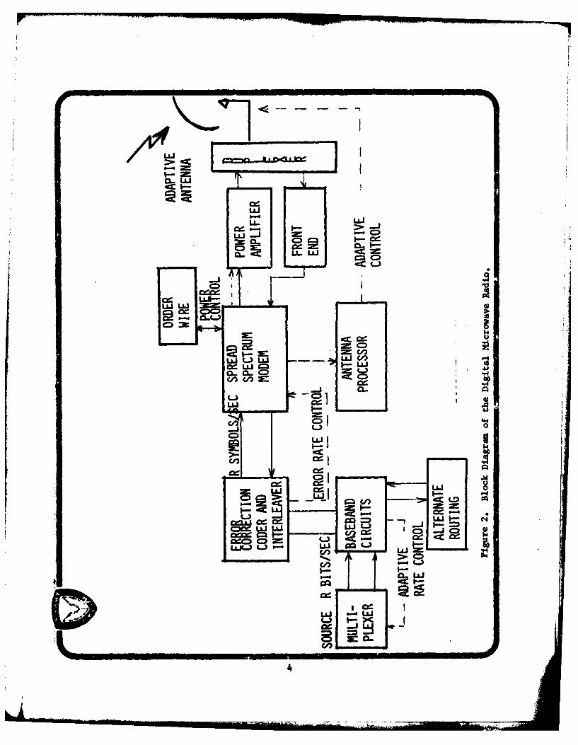
Figure 2 shows the system block diagram of the D14 illustrating the inter-connection of the major transmit and receive subsystems. Antenna discrimina-tion is achieved through a combination of antenna nulls directed at jammnerarrival angles and low antenna sidelobe response. The antenna systeminteroperates with the spread spectrum modem and coding equipment in amanner which provides the necessary ECCM performance.
Included in the %M system design will be considerations of alternaterouting and automatic re-routing of channel groups. Means will be providedto reduce the voice channel capacity or bit rate when the jamming environmentbecomes intolerable. The dropping of low priority channel groups in orderto provide increased protection for higher priority groups is a techniqueto be considered. The system design may also employ frequency or spacediversity both to overcome propagation effects and to minimize jaummingeffectiveness., Channel equalization techniques may also be incorporatedto optimize the demodulation performance in the presence of multipathor other propagation effects. Other techniques may be incorporated which.jivill overcome the weaknesses of present designs and avoid the choice ofcircuit designs which may prove to be vulnerable to sophisticated attack.
Spread spectrum techniques include Direct Sequence (DS) modulation bypseudo-noise sequences and Frequency Hopping (FH) of the informationspectrum and error correction coding. Error correction coding of theInformation bits Is a powerful bandwidth expansion technique because it addsredundancy in a carefully chosen pattern to facilitate minimization of erroro3In detection. The discrimination against the jammer as the result of errorcorrection coding is generally greater than the bandwidth expansion factor.,
3
LJ
LL L&J
LL -
Cl 0CDI
LLLU
LU I- 4'
CD,
C-/,
LU f-)LU LU
I-.H
4 : 4
Li _____ 0Ol __________

The code rate, which is defined as the ratio of information bit rate to thebit rate of the sum of information and redundant code bits, is thereciprocal of the bandwidth, expansion factor. It is Important to selectefficient and practical error correction decoders and minimize decodingdelays. only a fraction of the total increase in bandwidth can be realizedwith error correction coding techniques. The remainder 3f the, bandwidth
expansion must be provided by simpler and less powerful techniques.
Pseudo noise (PN) sequence modulation in the Direct Sequence technique ~increases the bandwidth by a factor equal to the number of PN chips perinformation bit. Against continuous jammers this technique provides aJammer discrimination factor approximately equal to the bandwidth. expansionratio, WIR. The autocorrelation function of the PN sequence over one bitinterval determines the spread spectrum processing gain and the j ammerdiscrimination.
The effect of pulse Jammers on the DS system can be reduced to nearlythe same as continuous Janmmers of the same average power through thejudicious application of interleaving and the error correction coding usedfor initial bandwidth expansion. As in the coding system, the DS spreadspectrum is also application limited by practical considerations. Becausethe synchronization time for acquiring the PN sequence at the receiver isproportional to the bandwidth expansion factor, very large expansion factorsmay mean a long synchronization time. With large spread ratios, many otherus ers in the band may suffer interference. These difficulties can beovercome, at a cost of some performance loss, by obtaining some of thebandwidth expansion with a frequency hopping technique. Frequency hoppingrequires special synthesizers and filter banks. Large bandwidth expansionin a microwave radio relay application can best be achieved with- a hybridsystem which includes a combination of error correction coding, directsequence modulation, and frequency hopping.
The bandwidth expansion is limited by RF bandwidth restrictions and inter-ference considerations, and by the minimum data rate. It is desirable,therefore, to achieve as much of the jammer discrimination from the antenasystem as possible.
The factors which must be considered in providing Jammer discrimination bymeans of the antenna system include:
0Location and quantity of Jammers and their power levels
0 Jaimer modulation techniques and strategies
0Multipath fading
0RF components differential delay and amplitude distortion
a Transmitter to receiver coupling
0Mast wind motion and weight limitations
a Antenna reflector blockage, asymmetry and surface tolerance
0 Overall radio
system costs
Because the spatial distribution of main heam jammers varies with time,antenna nulling of these jammers requires some form of adaptation, Adaptivealgorithms for this purpose include power inversiono reference and decisiondirected Least Mean Squares, random search, Gram-Schmidt orthogonalizationand others. Each of these algorithms provides certain performance, imple-mentation, and cost factors to be considered in a system design.
The spread spectrum modem in the ]MR will be a hybrid incorporating errorcorrection coding, direct sequence modulation, and frequency hopping.Some of the considerations in the design and development of this DRsubsystem include
" processing gain
" performance as a function of jammer modulation type
" pulse jammer performance
• emission bandwidth and spectral shaping
0 transmission system control - overhead bit rate
* means of incorporating alternate routing.
" detection of spread modulation, coherent or incoherent
* method of generating the frequency-hop signals
" frequency hopping rate
• data rates to be transmitted
" interoperability with the antenna and coding system
" frame and multiplex signal structure protectionagainst Jammer attack
" quality measure requirements and outputs required forantenna nulling
* system cost
Error correction coding in the LMt provides efficient bandwidth. expansion.Coding in conjunction with interleaving is essential in order to combatpulse jamners. The analysis and evaluation of jammer strategies with respectto coding is critical since weaknesses in the coding approach might allowintelligent jammers to more than offset the bandwidth expansion gain.Partial frequency band jamming must, in particular, be considered. On theother hand a properly designed coder/interleaver system offers the potentialfor greatly reducing the effectiveness of pulse jamming and of eliminatingtransient weaknesses in the remainder of the ECQ4 radio. Some of the majorfactors to be considered in the coder/decoder design are
• degree of bandwidth expansion realizable with practical decoder design
• interleaving vs. burst error codes for protection
• coding gain against background noise
" signal delay through the coder and interleaver6

The MM4 design will incorporate the three techniques effort into a modularizedadaptive system.
We have begun exploratory development of a null steering antenna, a spreadspectrum modem, coding equipment and a system design effort. These effortsare being accomplished concurrently and will provide the technology develop-ment necessary for us to proceed with advanced development of the digitalmicrowave radio set in fiscal year 1983. Included in this effort are ananalysis of the threat and calculations of the ECCM performance of the modem,coding equipment, antenna, and overall radio system. We are postulatingoptimum jammer strategies against each chosen technique and examiningpotential weaknesses of these techniques. We will incorporate alternativedesigns, additions, modifications and improvements and determine theperformance improvement resulting therefrom. This effort will continuethrough the exploratory development phase. Among other system considerationswe have or will analyze are graceful degradation, frequency and space diversity,orderwire design, routing techniques, adaptive bandwidth, power and bit ratecontrol. We must analyze various modulation, processing, spreading, antennanulling, coding, synchronization and framing techniques. Computer basedsystems analysis may be used to determine the weakness or vulnerability toJamming threats of the proposed techniques.
3. NULL STEERING ANTENNA. The null steering antenna development will providetechniques to null main beam jammers and reduce the effectiveness of side andback lobe Jammers. It must be designed to be compatible with spread spectrumand coding techniques. The antenna will be designed for duplex operation.An antenna will be designed to operate in the 4,4-5.0 GHz band, see figureand an antenna with minimum component change, in the 14.4-15.35 GHz band.Because of program funding limitations, only the 4.4-5.0 GHz design will befabricated and tested on this exploratory development effort. The antennawill be designed for a main beam gain of 30 dBi at C-band and 40 dBi at Ku bandwith 0 dBi side and back lobes and will have a maximum sail area of 15 squarefeet. The antenna shall weigh 300 pounds or less so that it can be supportedby a lightweight tactical quick-erection mast. The C-band antenna will be aparabolic reflector with offset multi-mode feed horns. A phased array approachis under consideration for Ku band. Various types of jammers and levels ofJamming have been included in the analysis of the proposed techniques. Amongthe technical areas requiring analysis and judgment are IF versus RF processing,propagation effects, implications of coding and modem design on the antenna,acquisition techniques, bandwidth requirements, self interference, referencesignal requirements, polarization effects, diversity techniques and systemtransient response time. See Figure 3,
The antenna technique chosen for the DHR in the 4.4-5.0 GHz band is a parabolicreflector with an offset feed. See figure 4. A multi-layer, multi-modefeed horn is used, with a side lobe canceller located near the focus. Theantenna system uses a monopulse technique to provide sum and difference beams,which are used to form a null in the direction of a Jaimmer in the main beam.One of the features of the antenna system is a look ahead capability whereby
7

zc
-C 3E= 3E
2c C
z czCD,
C.UJ z t~y
=00 I.21pbC2 = I-
C.3 L8

II 0 42
PRA ASOL IC.
AWACO .UW7CA4R4ASSEMB0LY ap &
AN4D A7
Figure 4. Parabolic Reflector with Offset Feed.

the next hopping frequency is examined and weighting networks are adjustedprior to the actual shift to the frequency. In order to provide duplexoperation a split band approach is employed whereby transmission is limitedto the upper half (or less) of the band in one direction and to the lowerhalf (or less) of the band for transmission in the return direction. Inaddition to its null steering capability, the antenna will provide beamsteering to adjust the direction of transmission and reception to correctfor mast movement under wind conditions. (See reference 3.)
The more critical areas to be addressed in the antenna design include therequirement for full duplex operation with the frequency hopping modulation,the need to maintain low side lobes while forming a main beam null, achievingthe performance for all postulated Jammer waveforms, and angle tracking thedesired signal during mast motion and jamming.
The Steerable Null Antenna System (SNAS) design is shown in Figure 5. Thisdesign Incorporates main beam and near in sidelobe adaptive null steering, usingleast mean square (LMS) criteria, with direction of arrival of the desiredsignal, reference signal and look ahead as discriminants. The rf output ofthe multiport antenna system drives both the rf weighting element and thereference inputs of the adaptive processor. A channelized implementation ofthe adaptive processor with "look-ahead" that accommodates the frequencyhopping pattern of the modem waveform has been selected. The received signalsare dehopped to a constant i-f frequency channel matched to the signal bandwidth(i.e., approximately 10 MHz). Band-limiting enhances the Jaming rejectioncapability of the system and eliminates the need for wideband equalization.The use of "look-ahead," digital weight memory techniques, and rapid adaptationalgorithms permits rapid null formation and provides protection against jammersusing sophisticated jamming strategies.
The antenna uses a monopulse difference pattern that is capable of electronicsteering with the aid of the modem to provide the necessary discriminantbetween the communication and jamming signals as well as compensating forantenna motion.
A low sidelobe monopulse pattern is used for nulling main-beam jammers anda low gain auxiliary antenna is used to optimize null performance in thenear sidelobe region.
The Steerable Null Antenna System includes a beam steering signal trackingloop that maintains the antenna boresight during sway and tilt by closedloop control of a beam steering network. The beam steering loop makes useof both the array processing gain and modem gain in deriving amplitude andphase beam-steering control signals.
A main-beam processor loop makes use of frequency hop information from themodem to "look-ahead" and develops nulling weights for the upcoming hopfrequency while nulling with another weight set at the current hop frequency.In addition to the use of frequency hopping to separate the desired signalfrom the interference, the main-beam processor uses a spatial discriminantbetween desired signal and jammer which permits nulling in the main beamduring the reception of the desired signal and a jammer on the same frequency.
10

II
*1. U
110 J7 Q 't t 71

A sidelobe processor loop is used to cancel a jmmuer in the near sideloberegion. This processor also makes use of "look ahead" techniques to insurerapid null formation.
The need for a reference signal for proper operation of the null steeringantenna is based on the availability of an error signal to use as a criterionfor signal to noise optimization.
An excellent error signal in a least mean square (U4S) algorithm is thedifference between the received sample upon which a bit decision is to bemade and the correct value of that bic decision. When this difference issmall, good performance will result. In most applications, minimizationof the mean square value of this error gives virtually the same results asminimization of the bit error probability. It should be noted, however, thatan error signal which depends on the correct bit decision suggests a circularargument since it is the correct bit decision which our error signal andadaptive processor is trying to achieve. A solution to this dileama, calleddecision-directed, simply assumes that the bit decision is correct. A secondsolution, called reference-directed, generates an error signal only when aknown bit has been sent and received. Decision-directed 1215 algorithms haveapplication when Jamming is not a threat. When Jamming is present, it ispossible for the decision-directed error signal to cause the weights to lockon the Jammer as a desired signal and cancel the information signal. Thislikely possibility in the presence of strong Jammers precludes the use ofdecision-directed IMS algorithms in ECCM applications. The reference-directed error signal always contains the correct signal discriminant andthus always leads to correct convergence of the algorithm. The disadvantage.of the reference-directed requirement is that some fraction of the transmitpower must be devoted to the reference and algorithm updates can be made onlyduring reception of the reference bit.
Adaptation using reference bits rather than reference chips is preferablebecause it is the bit decision that counts in final system quality and notthe chip decision. This factor influences the rate of adaptation and themethod of inserting the reference.
Adaptation using reference bits means that the UdS algorithm must adapt atrates slower than the reference bit rate. Tracking of the fading of theinformation signal and wind fluctuation effects will require that the referencebit rate be much larger than fading and wind-induced channel rates. Sincethese rates are on the order of a few Hertz, no serious limitations in signaltracking is incurred.
For data rates of 72 kb/s and higher, a reasonable reference bit rate mightbe 72 kb/s which would reduce system margin by at most 3 dB at the lowestdata rate and less at higher data rates. Signal tracking of the reference-directed LMS algorithm would then be on the order of a few hundred Hertz.
The spread spectrum modem has to time-division-multiplex the reference bitsinto the transmit information stream, synchronize the reference bit generatorsat transmitter and receiver, and generate the LRS algorithm error signal to beused in the adaptive antenna combiner.
I1.2

I
4. SPREAD SPECTRUM MODEM. The spread spectrum modem development will providemodulation and demodulation techniques to reduce the effectiveness of awide variety of jammer types. The modem will be designed to operate at ratesof from 72 kbits per second to approximately 18 Mbits per second in factorof two steps. A modem will be designed to operate at C bend also at Ku bandwith a minimum of change in modules. The modulation technique chosen isOffset Quadra Phase Shift Keying. The basic technique is a hybrid combinationof frequency hopping, and direct sequence, spread spectrum. By change inmodulation rate, the error rate at various Jammer levels can be controlled.In order to accomplish this a continuous monitoring of error rate performanceand estimation of Jammer environment is required which can be accomplished bythe error correction coder. (See reference 4.)
The modulation system must be designed so that it can be synchronized andresynchronized under the maximum jmming environment. The modem will acceptcoded signals from the error correction coder and deliver a 3-bit quantiza-tion representation of the encoded signals to the decoder. The modem mustbe capable of providing a reference signal to the null steering antenna.
Direct sequence spreading is achieved by multiplication by a binary pseudo-random sequence whose symbol (or switching) rate is many times(I.e., W/R>) 1)the binary data bit rate. The spreading symbol rate is commonly called thechip rate.
With frequency hopping the spreading signal remains at a given frequency foreach bit or even for several bits. Thus, instantaneously, the signal is nowider than the data signal (without coding), but it hops to a new frequencywhich may be anywhere within the spreading bandwidth W. The hopping patternis usually controlled by a PN sequence.
One difference between the two techniques is that direct sequence spread signalsusually are demodulated coherently. With frequency hopping, on the other hand,the path phase shift at each hopping frequency must be determined for coherentdetection; hence this modulation is often demodulated noncoherently unlessthe hopping rate is sufficiently slow relative to the symbol rate which wouldallow a differentially coherent system to be used.
The spreading sequence in a DS modulation technique is commonly a pseudo-noise (PN) binary sequence with a long period compared to the informationsymbol interval. The long period insures that the jammer cannot easilydetermine the PN shift register connections and thereby utilize the same PNsignal to obtain a coherent jamming advantage. This approach has two limita-tions. First, the autocorrelation function over each information symbolinterval is pseudo-random itself and occasionally will provide poorer peak-to-average ratios. This means that the spread spectrum gain is somewhatreduced for these poorer autocorrelation functions. Long PN sequencesrequire considerable acquisition time to resolve the path delay ambiguityand align the transmit and receive PN generators. If the path delay isT seconds and the spreading sequence has a bandwidth B (chip interval of1/B for binary sequences), there is an ambiguity at the receiver of approximatelyBr chips which must be resolved before communication can begin. A synchroniza-tion system with a fixed acquisition probability requires an averaging time
13
-a j .. .. _ .' _ . . .2 _ . - _ _ _ -........ - ... -. ... .." ' ' .- " ." "

per chip to combat background noise. If this averaging time is A the totalsynchronization time is B'rA This dependence of the total synchronizationtime on the spread spectrum bandvidth B is a limitation on achievablebandwidth with this approach.
Frequency hopping systems are easier to synchronize than long PN sequenceDS system and are widely used when the spread spectrum bandwidth B is verylarge. Frequency-hopping technology has an advantage In achievable handspreading of one or more orders of magnitude over direct sequence spreadingtechnology. The FR systems also have the advantage that other users can beaccomodated within FH cells which are not used, on a non-interference basis.On the other hand, frequency hopping systems are limited by achievablehopping rate with the available hardware and are vulnerable to tracking ifthe hopping rate is slow.
Since direct sequence spreading can be coherently demodulated, it is usedwith coherent data modulation techniques such as binary PSK, QPSL andOffset-QPSK. Frequency-hopping on the other hand, is often used in conjunctionwith noncoherent modulation formats such as MFSK. When DS is used with moreefficient modulation schemes it will operate with a lower Fb/N 0 to achieve
the same jamming protection as noncoherent modulation schemes used with FH.
For reasons mentioned above, a hybrid FH/DS spread spectrum modulationtechnique will be used to exploit the efficiency of DS with the wider bandspreading capabilities of FR. A simplifier block diagram of a combined FH/DSModem is shown in Figure 6. The input to the modulator may be themultiplexer output or the output of a coder.
5. ERROR CORRECTION CODER. The coding equipment development will provide acoding technique which is a random error and burst error correction coder.These coding techniques are to reduce the required Eb/N °0 input to 4.5 dB
while delivering an output error rate of no more than one error in tenthousand bits. We have analyzed the spread spectrum modem and null steeringantenna techniques and developed an error correcting capability to optimizeperformance of the antenna-modem-coder combination. The coding equipmentwill be used to estimate the bit error rate of the received data and theseverity of the jamming environment. The coder developer has developed anoptimum method of introducing interleaving to protect against bursts of errors.We have analyzed the threat, the proposed modem and antenna approaches andthe multiplexer interface in order to devise the optimum coding/interleavingtechnique. (See reference 5.)
In general, spread spectrum processing gains can be achieved by using directsequence (DS), frequency hopping (PH), or coded sequences (CS). A codedsequence system is one in which a low rate block or convolutional code isused to spread the bandwidth. The bandwidth expansion factor is equal tothe inverse of the code rate, that is the code expansion factor (W/R l/r).
14

10PUT FROM4 Co -
UR CODER
Q~t) sin wit
~~GENER
FITE
RCIEIF IUE 6.SWe Dr R
si15t

For a fixed bandwidth expansion factor W/R and Jammer-to-signal power ratioJ/S (i.e., fixed E./N 0), a convolutionally coded sequence has a lower bit
error probability because of its more powerful error correcting capabilitieswhile the frequency-hopped (FH) spread spectrum system has the highest biterror rate. Alternatively if we fix the error rate to Pb a 10-5, then a
convolutional coded sequence will require an b/NO of 6 dB, a direct sequencespread spectrum system will require an F../N 0 of 13 dB. Since E./NO -
(W/R)(S/J), a coded sequence system will require a smaller bandwidth expansionfactor than a DS or FH spread spectrum system for fixed Jamming-to-signalpower ratio J/S. However, if JIS is large the required code rate r - P./Wto obtain an Eb/No of 6 dB would be extremely low. For a fixed performance
leve, decoder complexity relative to DS systems and significant delaysintroduced by the decoder are disadvantages in this application. For coderates less than about 1/10, the additional performance advantage of the purecoded system is negligible. A good compromise between coded sequences (orcoded MFSK) and direct sequence or frequency hopping spread spectrum systemare hybrid systems which utilize both coding and spread spectrum. Becausedirect sequence spread spectrum is limited in bandwidth spreading by hardwareconstraints and acquisition time, a hybrid system using a combined directsequence/frequency hopping technique to further spread the signal after coding,achieves a higher bandwidth expansion than would be possible with just directsequence band spreading.
It already has been established that the jamming margin (maximum tolerablejamming power-to-signal-power ratio) afforded by spread spectrum signals inthe presence of wideband jamming is directly proportional to the band spreadingfactor, W/R, and inversely proportional to the minimum bit energy-to-noisedensity ratio needed to support a given bit error rate, Eb/N0 . Hence,
J = W/R
If coding is used along with spread spectrum, or instead of spread spectrum,a greater Jamming margin J/S can be achieved with an equal band spreadingfactor W/R, or equivalently, an equal Jamming margin with a smaller band-spreading factor.
Pulse Jamming is particularly effective against coherent systems. Considerwhat the effect of pulsed interference can be for an uncoded system. TheJamming may be present only a fraction p' 1 of the time, but during thistime, the noise density level is increased to a level N0/p Watts/Hz.
16

This assumes an average power rather than a peak power limitation on thejaumer. The noise is intermittent, and hence only corrupts a given transmittedbit with probability p but with higher noise density N0 /p. Clearly the
jammer would choose the low duty factor p which maximizes the bit error rate.As an example, if we desire a bit error rate performance on the order ofPb a, 10-5, stationary noise (or Jamng) requires only Eb/No equal to
(W/R) (S/J) 0 10 dB, while with pulse jamming we must have Eb/NO M 45 dB, an
increase in required processing gain (for fixed J/S) of over three orders ofmagnitude, i.e., 35 dB.
Coding can almost fully restore this 35 dB loss. Spreading causes this toappear at the receiver as wideband noise of density level N0 /p but for a
reduced duty factor p. Suppose that we construct a device which randomlyinterleaves the order of the symbols prior to transmission, but after coding,and puts them back in the right order after reception but before decoding.The deinterleaver which restores the transmitted symbols to their right placein order actually scrambles the jamming pulses into random patterns, allowingthe decoder to restore the required low error rate output.
The error correction coder design concept employs a constraint length K-7,rate r - k convolutional code with Viterbi decoding. This design meetsthe requirement of no more than one bit error in 10,000 bits at Rb/No - 4.5 dB.
As shown in Figure 7, the bit error rate for the selected code with 3-bitsoft-decision Viterbi decoding is less than 10- 5 at Rb/No - 4.5 dB when
operating over an Additive White Gaussian Noise (CAGWG) channel.
In order to maximize the efficiency of the coder-decoder (CODEC), the basebandsignal provided by the modem will be the optimum (maximum likelihood) metric.Generation of the optimum decoder input requires estimation of the channel stateinformation. Channel state estimation is performed by the modem, which quantizesthe metric to 3-bits before sending it to the CODEC system. Increasing thenumber of bits per sample to 4 results in only a small improvement in performancewhile significantly increasing the memory requirement of the deinterleaver andthe complexity of the decoder.
The quantized baseband signal from the modem is fed to a pseudorandomconvolutional deinterleaver. Interleaving is employed to provide protectionagainst pulse Jsming. The coder block diagram is shown in Figure 8.
6. PROPAGATION EFFECTS. Since the DHR will operate in the 15 GHz as wellas the 5 GHz frequency band, atmospheric attenuation is a significant factorIn designing the system. The radio set will include adaptive techniqueswhich will respond to varying jamming levels to provide the optiwmthroughput. The radio set will also respond to varying signal levels
17

-7-I
-. ........ f
........ A . ." ..
.1 7 ...,.
- .-.. ..
.......- -.
.... ... . . . .. .. . ....
*e
- . . .I... '- - - "- : .' " ; - " I .. - a' e"q
........ : ... . ... .-* I . .-... ,
s: : ' " : ... ..:: "- . . .
. ... .. . .. . I ' . .. , - - -: . . .. -:. . . ..
-'-- . -1. , ".' ,. ,. I S. .. -. ..-. : . .
.,. i-A
,,., -.., .... ..- -,;I .. . .. .. :.. ,,'6
..... . .t"':.' -. . ;: - '- .: : !I . .i :
• .' - '- 'I........... ............ " t... ....-
-5 -- .... . * " .. .- ..-.=. :.!-
...*- ' --. - -2 .. . . . .
* 1 .- .
* "'
Coputer Simulated Perfozmnce of alilura 7. Constraint Length 7, Rate 1/2 Convolu-
tional Code vith 3-bit Soft-Dac!.sionViterbi Decoding in Conjunction withIWSK over an AWGN Channel.
18

2 a
z
1*1W
Z020
ow
00-9
ILUI
.j.
0'
zo,,
0 is W
4c 00
I-I
W1

resulting from rain attenuation conditions along the path. Especially at15 0Hz, the effect of rain attenuation on the desired signal and the jammningsignal is a major factor in the system design and in the network performance.The need for wide spectrum occupancy rules out the use of frequencies below10 0Hz in many areas. The primary concern at 15 GHz is the rain attenuationwhich will be experienced.
The signal received over microwave radio paths also varies with time asa result of irregularities in the refractive index of the atmosphere.This fading is characteristic of multiple path propagation caused by anatmospheric layer of abnormal refractivity located in the transmission path.Fades of 28 dB depth are predicted 0.1% of the time.
The effects of rain and multipath fading are analyzed in Reference 6.18 dB depth fades may occur 1% of the time. Also note that signals 5 dBabove normal may occur 10% of the time and 10 dB above normal about 1.0%of the time. The latter effect may cause an increase in jamming signallevel of 5 to 10 dB while not necessarily increasing the desired signal duringthis period. In fact for other than main beam jamming it may be expectedthat the periods of enhancement of two signals will be uncorrelated.
Rain in the most significant cause of signal propagation attenuation at15 0Hz. The reduction in received signal will vary from .002 dB/km ata rate of 0.1 mm/hr to 7 dB/km at a rate of 100 mm/hr. The time distributionof rain intensity varies widely with geographic location.
In order to determine the effect of rain on a communications network, amodel of the expected rainstorms was formulated. A cylindrical rain cellmodel is assumed. The diameter of the rain cell will vary with rain rate;for rain rates of 32 mm/hour or more the rain cell diameter will be30 kcm or less.
A typical deployment of the MMR assumed in the above reference is shown infigure 9. Path lengths were assumed to be 50 kcm, nominally, with someshorter. Two jasmmers were assumed, placed as indicated, approximately 100 kmfrom the network. The effect of rain on both the desired signal and on thejamming signal for the values of rain cell diameter were calculated. Ineach case the rainstorm passed directly across the commuunication network.In each case the time each desired signal path was in the rainstorm, theamount of time both jammer paths to any given terminal were disrupted byrain and the rain attenuation on each jammer and signal path were determined.It should be noted that for rainstorms of 30 km or less, there was never asimultaneous reduction in both jammer signals to both terminals of a path.It was only when the storm diameter approached the nominal path lengththat some jaimmer signal attenuation was simultaneously experienced fromboth jammers. Jammer signal attenuations of up to 30 dB were noticed inrare cases. At a storm diameter of 90 km most of the paths in the network
20

2 4
6A
14
Figure 9. Typical Deployment of the Digital Microwave Radio.
21
______________

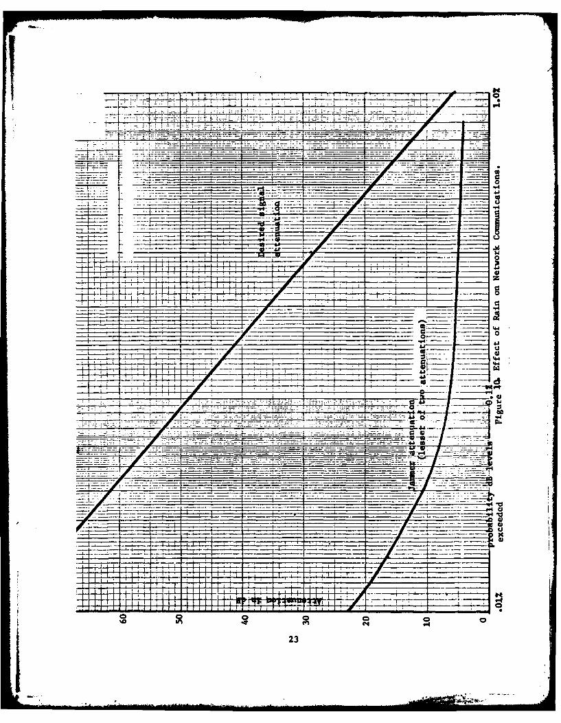
were affected by rain attenuation. However, at this rain rate the maximumattenuation was 15 dB. The 150 kmn rainstorm enveloped the entire network.However, the rain was so light as to cause oniy a maximum of 5 dB pathattenuation, in those cases. The effect of rain on the network conmmunicationsis shown in figure 10.
It can be seen that the jammer power received from at least one of thetwo jaimmer sources is attenuated very little, compared with the signal.This is a result of the small likelihood of rain cells simultaneouslycovering a significant portion of widely separated paths.
Figure 10 indicates that the communications system designer would berequired to provide 42 dB of margin to compensate for the difference inrain attenuation on the desired and the jamming paths to avoid outages ofmore than 0.1%. 55 dB of margin is required in order to reduce outagesto .03% of the time.
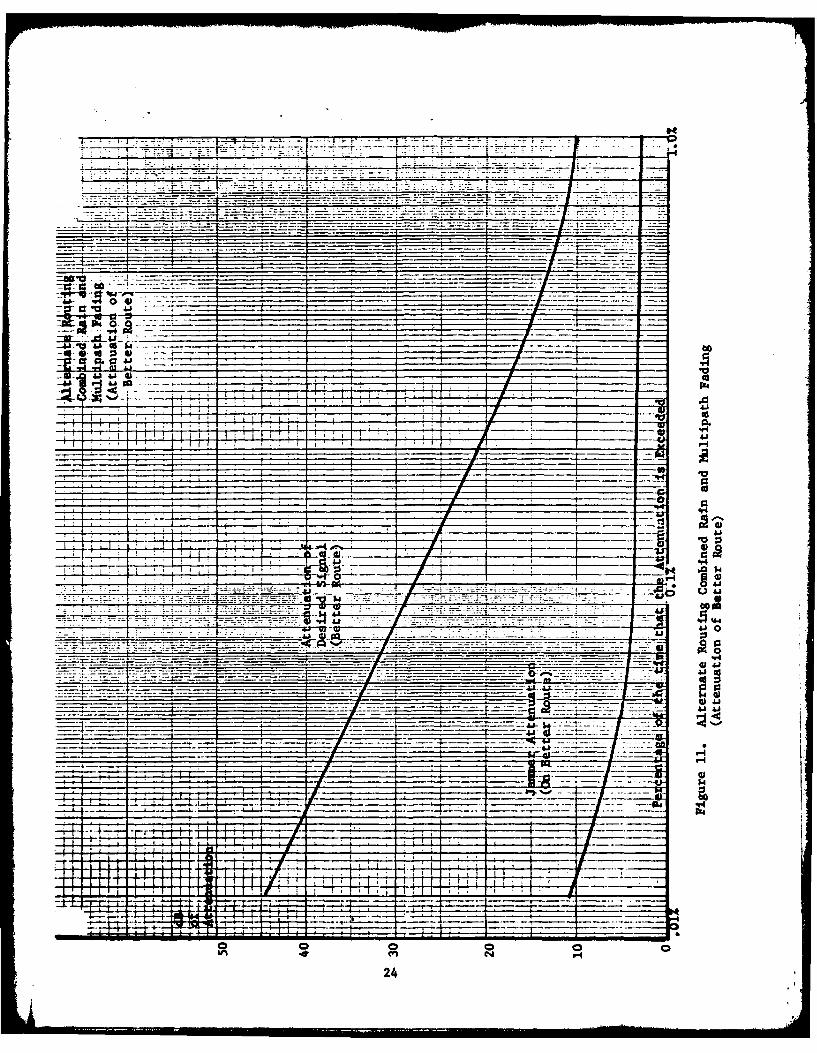
In view of the high values of signal attenuation caused by rain at 15 G~z,alternate routing of signals should be used during periods of heavy rain.The effect of rain attenuation on the parallel combination of direct andalternate route for each path was determined for each rain cell size andrain rate.
The method employed combined the fading effects of rain and multipath-onthe assumption that these effects would not occur simultaneously, Thereis evidence to indicate that severe multipath is most likely on clear nights.Therefore, it is reasonable to design radio circuits to operate with fadeswhich occur for the sum of the fading periods of multipath and of rain.
Sincethe jammer attenuation will not be increased any significant amount of time,the curve remains unchanged. Note that during the 10% of the time that thejammer signal may be enhanced by multipath, no rain is likely in the area.Therefore the system margin against rain and multipath should be sufficientto negate this enhancement.
The reduction in combined rain and multipath fade margin as a result ofalternate routing is shown in figure 11. It is seen that a 28 dB fademargin (24.5 dB J/S margin) is required for 0.1% outages and a 40 dB fademgin (32 dB J/S margin) is required for .03% outages. The use of alternate
routing, therefore, provides from 18 to 23 dB reduction in the required marginto overcome rain attenuation on this J ammed communications network.
7. STRATEGIC APPLICATION. In addition to being responsible for its owntactical LOS links, the army is the principal military operator of strategicLOS links for the Defense Communications System. Because of this dual capacity,the design concept for a generic ttlR should satisfy both the strategic andtactical needs. We have broadened our DI4R system design to incorporatethe requirements and design characteristics of a generic DMR f or the 1990'stime frame, which will meet both tactical and stragegic requirements.
22
S0r4
I W.
___ ~~F= _______ __7 ca
is -10
w.=7~
23
77"__ -7.-
4 9-4
24

The investigation will attempt to maximize aspects of commonality fortactical (division and above) and strategic (fixed plant and a reconstitutionrequirement) users in order to simplify logistic problems (Ouch as spare partsinventory), control interface characteristics and obtain optimum performanceat minimum cost. The analysis will be comprehensive, and include such con-siderations as interoperability, conmonality, modularity, survivability, andelectronic counter-countermeasures,
We will develop a design concept that will satisfy the requirements andperformance characteristics that vere defined as a result of the analysis.The design concept will emphasize coimonality, will consider techniques isuch as building block concepts and interchangeable common modules, andwill balance the tactical need for ruggedness versus the strategic needfor cost effectiveness without the stringent environmental requirements.The design will consider the feasibility of adaptive techniques that will
provide maximum throughput during ideal benign conditions, and will restrictreconstitution radio will reflect the philosophy that (at least initially)it will maximize speed of establishing reasonably reliable communicationsto critically essential users. The tradeoff will be against full normalthroughput and reliability. For the reconstitution radio, reliability ofthe initially re-established link in the order of 95% is acceptable. Thefeasibility of a design which allows field augmentation to build up thecapability of the reconstitution radio to a full throughput and reliabilitystatus, as time and resources permit, will be investigated.
The design will consider the optimum modulation techniques. Attributessuch as robustness, spectral efficiency, implementation complexity, andsuitability for ECCK techniques will be considered. A sumary of therequirements and characteristics of the design concept will be given.An assessment of the technical risk and a base line performance specificationwill be prepared for the radios in the generic system.
We hope to be able to prepare procurement packages for the advanced develop-ment of the MMi during the spring of 1983 and to place an advanceddevelopment contract by January 1984. The advanced development contractis expected to take 24 to 30 months to complete. On this basis engineeringdevelopment could be completed by June 1988 and first production started inJanuary 1990.
We are now considering an additional exploratory development effort to startin FY-82 which would supplement the previously described program. Thisprogram is for the development of a Phased Array Distributed AmplifierAntenna (PADAA) * The PADMA will be an ECCM microwave low sidelobe antennawith a beam steering capability. This effort will provide the necessaryadvance in the state-of-the-art at Ku band to form a basis for technologyinsertion into the digital microwave radio progra.
25

8. CONCLUSION: The Digital Microwave Radio development will provide anow radio set for multichannel tactical and strategic use in the. 1990-2010time period which will have a high- degree of protection against Jamming.The DR will be designed in a modular fashion to allow the needed functionalbuilding blocks to be assembled to meet a variety of needs. Through the useof alternate routing and adaptive techniques highly reliable multichannelcommunications will be maintained even under severe environmental stress.The future requirements of both tactical and strategic users can be met bya family of DMR modules, from which can be selected combinations of equipmentto meet specific needs, while allowing maximum interoperability andcommonality.
2I
26
REFERENCES
1. "Is Tactical LOS radio effective in nuclear or electronic warfare?"by Major Gary P. Clukey, The Army Coumunicator, Spring 1981.
2. "Digital LOS Microwave Radio System Study," Report BOO1, DMR Design Plan,Contract No. DAAK80-81-C-0039, by Signatron, 28 January 1982.
3. "Steerable Null Antenna System," Report B001, SNAS Design Plan, ContractNo. DAAK80-81-0059, by Hazeltine, 16 March 1982.
4. "MR Spread Spectrum Modem - Design Plan Report," Report No. 6460,Contract No. DAAK80-81-C-0073, by Hazeltine, 26 February 1982.
5. "DMR Radio Coding Techniques Design Plan," CDRL BOO1, Contract No.DAAK80-81-C-0050, by Harris Corporation, February 1982.
6. "Propagation Effects on the ECCM Performance of the DMR," by J. E. Bartow,AGARD Symposium on "Propagation Effects in ECM Resistant Systems onCommunication and Navigation," May 1982.
* U.S. GOVERNMENT PRINTING OFg#CS: 0O73/FM-C-7-52
27
HISA-F-1328-82

'DATE
ILME