ad-a260 236 i r 11 l 'i - apps.dtic.mil · versatile enough to provide both ct type images for...
TRANSCRIPT

AD-A260 236I 11 l 'I r 111AD
CONTRACT NO: DAMD17-88-C-8203
TITLE: A MULTI-MODE X-RAY IMAGING SYSTEM WITH ONE-SIDEDCT CAPABILITY DTIC
PRINCIPAL INVESTIGATOR: J.W. Motz ELECTEFEB 16 1993.J
CONTRACTING ORGANIZATION: Rayex Corporation9701 Fields Road #1605Gaithersburg, MD 20878
REPORT DATE: February 20, 1990
TYPE OF REPORT: Phase I Final Report
PREPARED FOR: U.S. ARMY MEDICAL RESEARCH AND DEVELOPMENT COMMANDFort Detrick, Frederick, Maryland 21702-5012
DISTRIBUTION STATEMENT: Approved for public release;distribution unlimited
The findings in this report are not to be cor-strued as anofficial Department of the Army position un. ess so designated byother authorized documents.
93-02789
APPENDIX BDOD No. 88.1
U.S. DEPARTMENT OF DEFENSE
SMALL BUSINESS INNOVATION RESEARCH (SBIR) PROGRAMPHASE 1 - FY 1988
PROJ&.T SUMMARY
Topic No. 192 Military Department/Agency ARMY.
Name and Address of Proposing Small Business Firm
Rayex Corporation9701 Fields Road #1605Gaithersburg, MD 20878
Name and Title of Principal InvestigatorDr. J. W. Motz, Research Director
Proposal TitleA PORTABLE MULTI-MODE X-RAY IMAGING SYSTEM WITH ONE-SIDED CT CAPABILITY
Technical Abstract (Limit your abstract to 200 words with no classified or proprietary information/data.)
The goal of this project is to develop an X-ray imaging system with three operating modes, including (1) a CTMode with an open one-sided geometry providing complete or partial CT type image slices with arbitraryorientations and shapes, (2) a Transmission Mode providing conventional transmission images, and (3) aFluoroscopy Mode providing real-time images. Because this versatile, open system offers immediate accessto wounded soldiers with one third the weight and cost of conventional CT systems, it is especially suitablefor combat casualty care.
This Phase I program was carried out with a simplified one-sided CT system which can provide tomographicimages with X-rays backscattered from different body volume elements penetrated by the X-ray beam. TheX-ray image sensor consists of an array of low efficiency plastic scintillation detectors which select and countthe scattered X-rays providing the image signal. With spatial resolution indicators used as test objects, theX-ray exposures and the digital outputs of the X-ray detectors were measured to determine the sigral-to-noise ratios, the spatial resolutions, and the minimum required X-ray exposures. The results show that withthe use of high efficiency detectors, this one-sided CT system is capable of obtaining spatial resolutions from2 to 5 Line Pairs per cm with an average patient dose per slice of less than 2 rads per image slice, or aspatial resolution greater than 7 Line Pairs per cm with an average patient dose of 5 rads per slice, which isthe dose requirements for present CT systems. These results establish the technical feasibility and potentialadvantages of this one-sided system for medical diagnostic services.
Anticipated Benefits/Potential Commercial Applications of the Research or Development
The development of a radiological diagnostic imaging system that is rugged, portable, easily accessible, andversatile enough to provide both CT type images for the detection of internal bleeding and nonmetallicforeign bodies and conventional transmission images, will greatly enhance the diagnoses, triage, andsurgical care of combat casualties at Medical Clearing Stations and Mash Hospitals. In addition, the lowcost, low mass, and cube of the system, and its ability to provide digitized images, will make it an importantdiagnostic tool in the equipment inventory of the Emergency Rooms in civilian hospitals. A( ,.., v ,
DI~LC Uh6k
List a maximum of 8 Key Words that describe the Project.
Tomography, Backscattered X-rays, Multi-mode, One-sided CT, -..X-Ray Slot Camera, Digital Radiography ,.--
DTIC QUALITY i1SPECTED 3
Nothing on this page is classified or proprietary informationidata D Spec !,IProposal page No. 1

20 February 1990 Phase I Final (8/15/88 - 2/15/89)
A Multi-Mode X-Ray Imaging System with Contract No.One-Sided CT Capability DAMD17-88-C-8203
J. W. Motz
Rayex Corporation9701 Fields Road #1605Gaithersburg, MD 20878
U.S. Army Medical Research & Development CommandFort DetrickFrederick, MD 21702-5012
Approved for public release; distribution unlimited
Tomography, Backscattered X-rays, Multi-mode, One-sided CT, X-ray Slot Camera, Digital Radiography,RAD II, SBIR
Uncla. ."ied Unclassified

I. INTRODUCTION
The development of a radiological diagnostic imaging system that is rugged,light-weight, and low-cube, and that has a digital format with the capabilityof producing both conventional and CT-type images will greatly benefit themilitary services. Such an imaging system could be freely moved to fieldstations and could provide the most advanced radiological diagnostic serviceseven at the smallest medical facilities. With tomographic capability, thissystem will be able to readily detect internal bleeding, embedded nonmetallicforeign bodies, and damage to internal organs. For the physicians andsurgeons at the Medical Clearing Stations and the Mash Hospitals, thiscapability will greatly enhance the diagnosis, triage and surgical care ofcombat casualties. As a consequence, there will be a reduction in themortality rate and an increase in the "retarn to duty" rate for wounded militarypersonnel.
The Rayex Corporation proposes to develop a versatile x-ray imaging systemwhich is specially designed for combat casualty care. This system, asillustrated in Figures 1 through 6, will have the following features:
* Three distinct diagnostic operating modes(1) The CT Mode with an open one-sided geometry providing
complete or partial CT-type image slices with arbitrary orientationsand shapes as shown in Figures 1, 2, 3, 4, and 5.
(2) The Transmission Mode providing conventional transmissionimages with either screen-film cassettes or digital image sensors asshown in Figures 2 and 6.
(3) The Fluoroscopy Mode providing real-time transmission images asshown in Figure 6.
All of the above capabilities which are presently provided by different x-ray systems are combined into the single Rayex Multi-mode X-rayImaging System. In addition, the capability of taking partial slices willpermit the radiological examination to be confined only to the c'iticalbody regions of interest. This feature of the Rayex System greatlyreduces the total body exposure received by the patient in comparison tothe exposure received with present day CT systems which requirecomplete axial slices over a large section of the body. No x-ray imagingsystem can presently offer this unique capability.
Highly PortableThe total weight of the Rayex System (exclusive of the power supply)will be approximately 400 pounds or less than one third the weight ofpresent CT scanners.
-2-

,t
* Highly AccessibleThe open one-sided operation of the Rayex System will provideimmediate and easy access to wounded soldiers and will greatly expeditethe process of diagnosis, triage, and treatment.
* InexpensiveThe total cost of the Rayex System will be less than one-third the cost ofcurrent CT scanners.
* Reduced Patient TimeThe Rayex System will be able to throughput patients faster then presentCT systems, partly because of its one-sided easy accessibility (seeFigure 1). In addition, the capability of the Rayex Imaging System to dodirect partial CT-type tomographic slices of only critical regions willdrastically reduce the time required for many patients who do notrequire full axial slices for proper diagnosis. (Present CT systems canonly take full axial slices whether they are actually needed or not.)
Variable Spatial Resolution for CT ImagesThe Rayex System will have the flexibility of changing the spatialresolution of CT images from 2 to 5 Line Pairs per cm by simplechanges in the apertures of the slot and the x-ray beam collimator. Thelow resolutions (such as 2 LP/cm) permit fast scans with low exposures.The high resolutions (such as 5 LP/cm) require slower scans and higherexposures. For partial body scans, the reduction in the irradiated bodyvolume will permit higher x-ray exposures with less risk andconsequently higher spatial resolutions (up to 5 LP/cm).
* Fast Scan for Rapid Emergency DiagnosisFor rapid emergency diagnosis of wounded soldiers, the Rayex Systemwill provide fast scans for quick detection of internal bleeding. Rapiddiagnosis can be achieved by utilizing the one-sided accessibility of thesystem and by using only partial body scans with low resolution.
* Slow Scan for Fine Anatomic DetailThe Rayex System will have the capability to do direct partial CT-typetomographic slices which can be confined only to regions of interest.With a slow scan and higher exposures, the Rayex System will be able toproduce high resolution images of detailed anatomic structures (5 LP/cmor greater). These images will be superior to those produced by currentCT systems and will greatly enhance the diagnosis, triage, and treatmentof patients with wounds in areas that have fine, complex anatomy suchas the eye, the brain, the spinal cord, and the ear.
The multiple operational modes, of this proposed "all-in-one" field diagnosticimaging system is made possible by combining proven technologies with a
-3-

new technology. The new technology involves collection of backscatteredradiation (see Figures 3 and 4) to generate information which is thenprocessed to yield the desired tomographic images. The tomographiccapability (full or partial) of this unique imaging system win also make itpossible to readily detect bleeding tracts and embedded nonmetallic foreignbodies such as glass or plastic. The Rayex System will also producefluoroscopic images, or conventional transmission images, either on a film ordigitized format. This unique blend of existing and new technologies enablesthe Rayex Multi-mode, CT Imaging System to operate in the three separateand distinct operational modes. Furthermore, in contrast to the conventionalCT technique, the use of backscattered radiation makes one-sided operationpossible when doing complete or partial CT-type tomographic slicing as thereis no need to have an x-ray sensor surrounding the patient. Thus, this newtechnology will greatly reduce the weight and cube of the system, and willgreatly facilitate its use with seriously injured patients who are on a fieldlitter, gurney, or operating room table since these patients will not have to belifted off the field litter and placed in the aperture of a conventional CTimaging system. Finally, all image information can be generated in digitizedform and will be directly available for digital information manipulation,networking, and storage.
The Rayex Multi-mode X-ray Imaging System will provide a new one-sidedCT technology, which is based on the formation of tomographic images withx-rays that are backscattered (or reflected) from the different body volumeelements penetrated by the x-ray beam (see Figure 3 and 4). Previousattempts to produce images with backscattered x-rays have not been practicalbecause all of the different methods had inherently low sensitivities andconsequently required excessive x-ray exposures and exposure times. incomparison, the Rayex One-sided CT System, which is based on patentsissued to Dr. M. Danos, has sensitivities that are four to five orders ofmagnitude greater than any previous backscatter imaging system. Thisgreatly increased sensitivity will allow the Rayex System to operate withexposures that are comparable to present-day CT systems for the same imagequality.
-4-

U. PHASE I TECHNICAL OBJECTIVES
The Phase I Program is intended to demonstrate the technical feasibility andthe potential advantages of the Rayex patented one-sided CT system overconventional CT systems for combat casual.y care. This program will becarried out with a simplified version of the Rayex CT camera (Slot Camera)such that *he imaging system will consist of a limited array of 20 plasticscintillation detectors which will be used as the X-ray pixel detectors for thedigital solid-state imaging panel. Although these scintillators have a low X-ray detection efficiency, they are cheap and readily available, and thereforecan be utilized within the time and cost limits imposed in the Phase Iprogram. It is anticipated that in a Phase II program the array of 20 plastic X-Ray detectors will be replaced with an array of approximately I (,ý highefficiency X-Ray detectors.
The technical objectives of the Phase I program are as follows:
a. Determine the patient X-ray exposures required for obtaining spatialresolutions in the region from 2 to 5 Line Pairs per cm with test objectscontaining spatial resolution indicators.
b. Determine the final patient exposures required for obtaining spatialresolutions in the region from 2 to 5 Line Pairs per cm with specific highefficiency X-Ray pixel detectors utilizing well-known conversionfactors.
c. Determine scan times required for tomographic image slicescorresponding to spatial resolutions in the region from 2 to 5 Line Pairsper cm.
d. Design a high detection efficiency imaging panel which can providecomplete body-slice images and spatial resolutions in the region from 2to 5 line pairs per cm for the Phase II Program.
Ill. PHASE I PROGRAM
The Phase I Program was carried out by completing the following tasks:
a. Adapt a breadboard prototype of the one-sided CT system designatedhere as the Slot Camera system.
b. Design and construct test objects to demonstrate the spatial resolutioncapabilities of the Slot Camera system.
c. Measure X-ray exposure rates provided by the X-ray source for differentfiltrations and kilovoltages.
d. Determine the detection efficiency of the X-ray detector elements usedin the digital imaging panel of the Slot Camera.
-5-

e. Measure the digital outputs of the X-ray detector elements and thecorresponding X-ray exposure rates for spatial resolutions of 2, 3.3, and5 Line Pairs per cm.
f. Determine the minimum X-ray exposures and scan times required fordifferent spatial resolutions.
A description of the preceding tasks and the pertinent experimental details isgwen in the following sections.
A. THE SLOT CAMERA
The basic experimental arrangement of the Slot Camera System isshown in Figures 7. 8, and 9. In this system, the collimated X-ray beamfrom the X-ray source penetrates through the object of interest, and theX-rays scattered at approximately 90 degrees,, pass through the slotaperture to the detector array. Each detector counts X-rays receivedfrom a corresponding position in the object of interest (such as positionsI and 2 in Figure 9). Therefore the digital signals from the detectorarray give a density profile of the object's structure in the irradiatedvo.lume along the direction of the X-ray beam. The spatial resolutionand signal sensitivity of the Slot Camera are determined by the variousparameters discussed in the following sections.
1. SPATIAL RESOLUTION PARAMETERS.The parameters for the Slot Camera geometry are shown in Figures7, 8, and 9. These parameters are defined as follows:
r = length of the resolution element in the object of interest
s = width of the slot aperture
w = width of the detector element
L = length of the detector element
d = thickness of the detector element
a = width of the X-ray seam at the position of the slotaperture
b = thickness of the X-ray beam at the position of the slotaperture (also designated as image slice thickness).
o = angle between the intersection of the X-ray beam axisand the perpendicular to the plane of the slot aperture
1 Other scattering angles can be used according to the geometry used in the specific applications.
-6-

A = distance from the X-ray beam axis to the median plane ofthe slot aperture
B = distance from the entrance plane of the detector elementto the median plane of the slot aperture
M = magnification ratio, B / A
V = l2 . b = Volume element (voxel) in test object which issource of scattered X-rays
D distance from target of X-ray tube to midpoint of slotaperture
The spatial resolution, R, of the Slot Camera is determined byseveral of the above parameters. This resolution may be defined interms of Line Pairs per cm, such that
R = 1/2r
= M/2s(I+M) (1)
For a given value of R, the required slot width, s, is given as
s = M/2R(1+M) (2)
Likewise for a given value of s or R, the required detector width, w,is given as
w = s(l+M)
= M/2R (3)
The preceding equations indicate that the resolution R dependsprimarily on the parameters, M, s, and w. Generally the size of theX-ray beam is determined by r such that the volume element(voxel) in the object is proportional to r3. For larger beam sizessuch that the slice thickness, b, is greater than r, the value of Rpredicted by the above equations may be reduced.
The above relationships permit flexibility in the canera design suchthat the values of M and s may be adjusted to change either or boththe camera size and resolution with tradeoffs that either reduce orincrease the camera's signal sensitivity. This flexibility is apotentially important advantage of the Slot Camera over theconventional CT system to the extent that patient exposures andscan times can be greatly reduced.
-7-

2. SIGNAL SENSITIVITY PARAMETERSThe signal sensitivity of the Slot Camera may be defined as theimage signal per pixel per unit X-ray exposure incident on thepatient. The image signal per pixel is equal to the numbers of X-rays detected by a detector element in the Slot Camera as shown inFigure 9, where the detector elements, 1 and 2, receive the X-raysscattered from the corresponding volume elements at positions 1and 2 in the object of interest. For a given detector and spatialresolution, the number of detected X-rays is linearly proportional tothe quantity, JA2 , where I is the X-ray detection efficiency of thedetector element, and A) is the solid angle subtended by the detectorelement from a corresponding point along the beam axis as shownin Figure 8 and 9, such that
Aj %- (wL)/(A+B), (4)
According to the geometry used in the present measurements thevalue for'I* is equal to 0.0029. In the Phase II Program, the patientexposures required to produce a givgn image signal may be reducedby factors equal to the ratio n I J11 / N) H l u, where the subscriptsI and n apply to the detectors and geombtry used in the Phase I andPhase II programs respectively.
3. X-RAY DETECTORSAs indicated in Figure 9, the imaging panel consists of an array oftwenty X-ray detectors which operate in a digital format such thateach detector counts the X-rays incident on its entrance surfacedefined by the width, w, and the length, L. Each detector representsa pixel such that the spatial resolution is determined by the detectorwidth, w, the slot width, s, and the resolution length, r, as discussedin Section A.1.
In this Phase I Program, each detector element is a plasticscintillator (Bicron BC-400), such that w, d, and L are equal to 4mm, 20 mm, and 15 cm respectively. Each scintillator is connectedby a light pipe to a photo-multiplier tube as shown in Figure 10.The twenty X-ray detector elements were designed so that they aremounted adjacent to each other in a close-packed array as shown inFigures 11 (a), (b), and (c) where the adjacent detector assembliesdo not interfere with each other. A front view of the detector arrayfrom the direction of the slot is shown in Figure 12.
As discussed in Section A.2, the detection efficiency, • , of eachX-ray detector is an important parameter that determines both theminimum patient exposure and the scan time required to obtain agiven spatial resolution. This efficiency, which is defined as the
-8-

ratio of the number of X-rays counted by the detector to the numberof X-rays incident on the entrance surface of the detector, wascalibrated with a sodium iodide scintillation spectrometer. A 1 mmlucite scattering foil was placed at an angle of 45 degrees to thebeam axis opposite the slot aperture in Figure 7, and the X-raysscattered at 90 degrees were counted first by the plastic detectorsand then by the sodium iodide scintillation spectrometer (3 inchdiameter, 3 inch thick with a 1/2 inch aperture) for which the X-raydetection efficiency was approximately unity. From theseexperimental results, the detection efficiency for the plasticdetectors was determined to be approximately equal to 0.07.
With such a low value of 0.07 for the detection efficiency of theplastic scintillator, it is apparent that the sensitivity of the SlotCamera System can be greatly improved by using a detector withhigher density and atomic number. For example, a comparison ofthe detection efficiencies of the above plastic scintillator and asodium iodide scintillator (2 mm wide, 8 mm thick, and 100 mmlong) is given in Figure 13 as a function of the discriminator pulseheight setting which can be calibrated in terms of kilovolts. Theseefficiencies were estimated by carrying out statistical Monte Carlocalculations of the penetration and energy losses of mono-energeticX-ray in both the plastic and sodium iodide scintillators describedabove. In these measurements, most of the X-rays scattered at 90degrees have energies in the region from 80 to 180 keV with a peakenergy of approximately 110 keV. Accordingly as a firstapproximation, the Monte Carlo calculations were carried out for anX-ray energy of 100 keV. The results in Figure 13 show that theuse of sodium iodide scintillators in place of the plastic scintillatorscan improve the detection efficiency, I , by an order of magnitude.
To obtain estimates of radiation cross talk between the closelyspaced detectors in the array, additional Monte Carlo calculationswere carried out for incident X-ray energies of 50 and 100 keV.The results showed that the counting rate for the sum of twodetectors on either side of a radiation input detector is an order ofmagnitude smaller than the count rate for the irradiated detector.Also, the count rate for the sum of two detectors one set beyond thedetector pair adjacent to the irradiated detector is an additionalfactor of two smaller than that of the adjacent pair of detectors.These results apply to both the plastic and sodium iodide detectors.
-9-

B. X-RAY SOURCE
In this Phase I program, the X-ray source was a 250 Kilovolt X-raymachine which was operated in the D.C. mode at 10 milliarmps. The X-ray beam was filtered with a composite filter consisting of 5 mmaluminum plus 3 mm copper. The X-ray fluence spectrum for thisfiltered beam as measured in previous studies is shown in Figure 14. Forsome of the film measurements given in the results, only the 5 mmaluminum foil was used as a filter. Data on the spectral composition ofthe X-ray beam will be utilized in the future development of a prototypesystem, inasmuch as it may be desirable to modify the tube kilovoltageand filter composition in order to obtain an optimum spectrum whichprovides the smallest patient dose and scan times for the same diagnosticinformation in the X-ray image. A summary of the exposuremeasurements with this source will be given in the results.
In this Phase I program, the collimator for the X-ray beam was adjustedsuch that the beam dimensions, a and b, at position 1 opposite the slotaperture (as shown in Figure 9 and defined in Section A.1) were foundfrom film measurements to be equal to 1.6 mm and 6.9 mm respectively.The dimensions of this beam can be adjusted for different applications inorder to obtain the minimum scan times required for a given spatialresolution.
C. TEST OBJECTS
The test objects were designed to show the response of the Slot Camerato a periodic structure which can be interpreted in terms of theparameter, R, for spatial resolutions of 2, 3.3, and 5 Line Pairs per cm,which covers the region over which the conventional CT systemsoperate. The test object, which is designated here as a SpatialResolution Indicator (SRI), has six lucite sheets each separated by an airgap equal to the thickness of the sheet, as shown in Figure 15. Forspatial resolutions of 2.0, 3.3, and 5 Line Pairs per cm, the sheetthickness for the corresponding indicator is 2.5, 1.5, and 1.0 mmrespectively. Each indicator is placed at an angle of 45 degrees to theincident X-ray beam and as shown in Figure 7, the X-rays scattered atapproximately 90 degrees pass through the slot aperture to the detectorarray. Because of the limited number of detectors, the results will showthat only 4 lucite sheets of the 2 Line Pairs per cm indicator could beimaged by the detector array.
- 10-

IV. RESULTS
In accordance with the tasks described in Section mI, a summary of the resultsis given in the following sections. These results provide experimental data forthe spatial resolutions, the X-ray exposures and exposure rates, and the effectsof body thickness. From these data, the minimum X-ray exposures and scantimes are determined for the different spatial resolutions, and comparisons aremade for the corresponding requirements in conventional CT systems.
A. SPATIAL RESOLUTION MEASUREMENTS
The experimental arrangement for carrying out the spatial resolutionmeasurements is shown in Figure 7. It is important to note that nomechanical scan system is used in this arrangement because of the timeand funding limitations in the Phase I program. Accordingly, data isobtained with the X-ray beam fixed at one entrance point to the testobject, and the digital output of the detector array gives the densityprofile along the beam direction of the irradiated volume in the testobject (without corrections for the beam attenuation in the object).
As a first test to demonstrate the potential imaging capabiiities of theSlot Camera, a screen-film X-ray imaging system was substituted inplace of the detector array shown in Figure 7, and a reproduction of thefilm images of the three Spatial Resolution Indicators (SRI) are shown inFigure 16 (a), (b), and (c) for 5, 3.3, and 2 Line Pairs per cm. Theseimages were obtained with a 1 mm slot width and a 2 mm beam. widthfor the 2 Line Pairs per cm SRI, and with a 0.5 mm slot width and a 1mm beam width for the 3.3 Line Pairs per cm SRI. The raw imagesshow the density profiles and the effect of the X-ray attenuation from thedark to the lighter bands as the beam passes through the SRI from thetop to the bottom of the image.
In the second test, the digital outputs of the X-ray detectors are shown inFigure 17 for the 5, 3.3, and 2 Line Pairs per cm SRI test objects. Theordinate values are given in terms of the normalized counts per unit timewhich is equal to the ratio of the true count rate to a calibrated count ratein order to correct for the differences in the detection efficiencies of thedetectors. These efficiency corrections were determined from detectorresponse measurements with a standard X-ray source. The high and lowvalues in these normalized count histograms closely parallel the high andlow densities in the corresponding film images in Figure 16. Thedetector array used in this prototype system imposed certain restrictionson the digital output data shown in Figure 17. Because there are alimited number of detectors in the array, the length of the test objectmust be limited and for the Spatial Resolution Indicator corresponding to
- 11 -

2 Line Pairs per cm, only 4 instead of the 6 lucite sheets described inSection mII C, were used. Also, to obtain the digital outputs for theSpatial Resolution Indicator corresponding to 5 Line Pairs per cm, it wasnecessary to reduce the detector widths from 4 to 2 mm by placing leadabsorbers over half of the detector width and taking two separateexposures to cover the total image. Even with these reduced detectorwidths of 2 mm, there is an appreciable reduction in the modulationtransfer function for the spatial resolution of the system, as shown by thereduction in the peak-to-valley count rations as the resolution increasesfrom 2 to 5 Line Pairs per cm.
With an image processing system in the Phase II Program, thesenormalized counts will be corrected for the beam attenuation in the testobject and will have the digital format nece-Isary for image storage,image transmission, and video or hard copy image display. In addition,the software for the image processing system will provide the variousimage enhancement options such as contrast and edge enhancement,and/or histogram equalization. The final result will be an image displaythat accurately reproduces the structures appearing in any given regionof the test object.
B. X-RAY EXPOSURE MEASUREMENTS
The X-ray exposure measurements were made for the followingconditions:
a. The exposure rates were measured with a 6 cubic centimeterionization chamber (Model 10x5-180, MDH Industries Inc.), andare expressed in terms of the quantity, XD2 , where X is theexposure rate in Roentgens per second, and D is the distance in cmfrom the target of the X-ray tube to the midpoint of the slot apertureas shown in Figure 7.
b. The measurements were made with a 1.6 cm diameter collimatorplaced at the window of the X-ray tube, at a distance, D, equal to100 cm on the beam axis.
c. The measurements were made for X-ray tube kilovoltages of 100,200, 250, and 300 kilovolts in order to provide data that can be usedto optimize the kilovoltage for a given application.
d. For each kilovoltage, measurements were made for two differentfilters placed before the collimator aperture. The first filter was a 3mm aluminum foil, which was then replaced with a composite filterconsisting of 3.2 mm copper plus 5 mm aluminum.
A summary of the values obtained for the quantity, XD2, for thedifferent kilovoltages and filtrations is given in Figure 18. From these
-12-

curves, the exposure rate can be determined for any given distance, D.Exposure measurements were also made with the highly collimatedbeam sizes of 1.6 x 6.9 mm that was used to obtain the digital outputdata in Figure 17. Because this smaller collimator transmits X-raysemitted from a fraction of the focal spot area, the exposure rates with thesmall collimator were found to be a factor of approximately 0.56 of theexposures values given in Figure 18.
C. BODY THICKNESS EFFECTS
As the X-ray beam penetrates to different body depths, there is anincrease in multiple X-ray scattering processes and the generaleffect on image quality is to reduce the image signal to noise ratios(or the image contrast) in the portions of the image correspondingto increasing depths in the body. This general effect can bedemonstrated with a lucite phantom having different gapseparations as the penetration depth increases. This type ofphantom was imaged with a screen-film system in place of thedetector array which did not have enough detectors to image anobject length of 20 cm as described in the previous section. Theresults are shown by the two images in Figure 19 which wereobtained with and without a 7.6 cm lucite absorber interposedbetween the beam axis and the slot position. An inspection of theseimages which have not been enhanced by image processingtechniques, leads to the following conclusions:
* The image signal or image contrast decreases as thepenetration depth and absorber thickness increases.
* Spatial resolutions greater than 6 Line Pairs per cm aredetectable at various body depths. Practical limits indetermining, the depths of body imaging may be controlledaccording to the kilovoltage of the X-ray machine and the sizeof the detector array.
* Improvements in image quality at body depths greater than 10cm can be obtained with the use of anti-scatter baffles andwith image processing techniques. A Phase II program willshow how anti-scatter baffles can be designed and used in theSlot Camera to improve image quality.
* The effect of increases in body thickness is to increase therequired X-ray exposures and scan times. Estimates of theseincreased values will be given in Section D.
- 13-

D. MINIMUM DOSE REQUIREMENTS
The criterion for determining the minimum X-ray exposure, Xmin,that is required to achieve a given spatial resolution is based on theattainment of a minimum value of five for the signal-to-noise ratioof the image signals obtained with the Spatial Resolution Indicatorsof 2, 3.3, and 5 Line Pairs per cm. The method of determiningthese minimum exposure values as a function of the spatialresolution is described in the following discussion.
The signal-to-noise ratio, 6-, which is obtained with the exposure,X, measured at the position of intersection of the beam axis and theperpendicular extending through the midpoint of the slot aperture,is defined by the following equation:
ý (X) = ni - = (nn' 2 (1- n2/nl)(1/2 /2
(n + n2) (1+n2/nl)
where ni and n2 are the number of detector counts at the peak andvalley respectively of the histogram plots shown in Figures 17.
From the plot for a given spatial resolution, the ratio, n2 / n1 , canbe readily obtained by averaging the values for the peaks andvalleys. Then the value of ni in Equation (5) is determined byconverting the normalized counts shown in Figure 17, to the truecount rate by using the calibrated correction factors for theefficiencies as discussed in Section III A.3. Accordingly theminimum X-ray exposure, Xmin, required to produce a minimumsignal-to-noise ratio, 0 "mm,, offive is given by the equation:
Xmin/X = 0min16/" or Xmin = 5X /6- (6)
From the experimental values obtained by the above procedure fornj and n2, and the corresponding values for the exposure rates, X,experimental values for the signal-to-noise ratios, I", were obtainedfrom Equation (5). Then the minimum exposure values required toobtain spatial resolutions of 2, 3.3, and 5 Line Pairs per cm weredetermined from Equation (6). With the conversion factor of oneRoentgen equal to 0.88 rads for tissue, the minimum patient dose atthe position on the beam axis opposite the slot aperture wasdetermined for the above three spatial resolutions.
From the above results, the dependence of the minimum patientdose as a function of the Spatial Resolution is given in Figure 20.
- 14-

These experimental curves were determined for a fixed geometrywhere -.a is equal to 0.0029 (Section III A.2), a specific efficiencywhere -Yv is equal to 0.07 (Section III A3), a fixed voxel size suchthat V is equal to 8 mm3, and for tissue absorption thicknesses of 10cm and 20 cm for the scattered X-rays. These experimental curvesare used as a basis of comparison for the results that can beobtained in a Phase II program with larger values for Yt and V. Infact, the minimum patient dose for a given spatial resolution can bereduced by the factor, F, where F is determined by the followingequation:
F = AIVI 1 (7)11n. I VU YilI
where _2 , V, and "n are defined in Section IIR A. 1, with thesubscript I indicating thý values used in this Phase I program andthe subscript ] indicating the values that would be used in a PhaseII program. Values of F for different spatial resolutions that can beobtained in a Phase II program are given in Table 1, and theminimum patient doses obtained with these F values are shown bythe dotted lines in Figure 20 for tissue absorption thickness of 10cm and 20 cm for the scattered X-rays. Compared to these curvesin Figure 20, the average patient dose of 5 rads per slice that isrequired by the conventional CT system is shown by the dashedline.
Table 1. Dose Reduction Factor, F, for a Phase II Prototype
Spatial P a r a m e t e r sResolution Program "L V3 V FLine Pain per cm n= 3
2 Phase I .07 .0029 8.0 0.0016 -__ 0.0087Phase HI 1.0 .0030 63.0 0.19
3.3 Phase I .07 .0029 8.0 0.0016
Phase II 1.0 .0019 23.0 0.043
5.0 Phase I .07 0.0029 8.0 0.0016 0.13Phase II 1.0 0.0013 10.0 0.013
-15-

V. CONCLUSIONS
A. FEASIBILITY
The results obtained in this Phase I program have shown that withlow efficiency X-ray detectors, the patient dose required by the SlotCamera to obtain spatial resolutions from 2 to 5 Line Pairs per cm,exceeds the average dose of 5 rads per image slice required bypresent CT systems. However with further prototype developmentin which high efficiency detectors are used (sodium iodide forexample), the Slot Camera can exceed the performance of presentCT systems. The results in Figure 20 show that with highefficiency detectors, the local dose at the aperture position is 2.3rads, and with exponential decay of the X-ray beam i the body, theaverage dose per slice is approximately 1.9 rads. 6onversely if ahigh efficiency prototype is developed, the spatial resolution thatcan be achieved for the same average dose used by present CTsystems, becomes greater than 7 Line Pairs per cm. Additionally,for oblique image slices or for partial slices, the average dose forthe whole body may be at least an order of magnitude less than thepresent CT systems.
The above results apply to large body parts such as the chest orabdomen. For smaller body parts such as the head, neck, arms, orlegs, the Slot Camera can greatly exceed the performance of thepresent CT system inasmuch as much smaller patient exposures arerequired for a given spatial resolution, or conversely much higherspatial resolution exceeding 10 Line Pairs per cm can be achievedfor the same average body dose.
In summary, the above results establish the technical feasibility ofthe Slot Camera system. Compared to present CT systems, it offerslow mass, low cube, low cost, low radiation burden for the body,and flexibility to permit tradeoffs in spatial resolutions, body doses,and scan times. In addition it will have the versatility to operate inconventional transmission or fluoroscopic modes, as well as the CTmode. These potential features of the Slot Camera system offerpowerful advantages over present CT systems.
B. FUTURE PROTOTYPE DEVELOPMENT
As indicated in the preceding Sections, the Slot Camera System is readyfor the development of a highly practical and useful prototype which caneventually be used for combat casualty care. This prototype willincorporate the following features:
-16-

* An image sensor array with high detection efficiency and with 100detectors capable of imaging a 20 cm penetration depth.
* A small DC image processing system capable of performingvarious image enhancement processes as well as storing andnetworking archival images.
A baffle system capable of greatly reducing multiple scatteringeffects for large body thickness.
A mechanical Scan system that will provide simple partial orcomplete body scans.
A dedicated X-ray source which will be incorporated into a scanhead for the prototype system.
-17-

FIG. 1" Illustration showing the Rayex Multi-mode X-ray Imaging System positioned
over a patient's chest ready to take complete or partial CT-type tomographic slices with
arbitrary orientation, size, and shape.
- 18 -
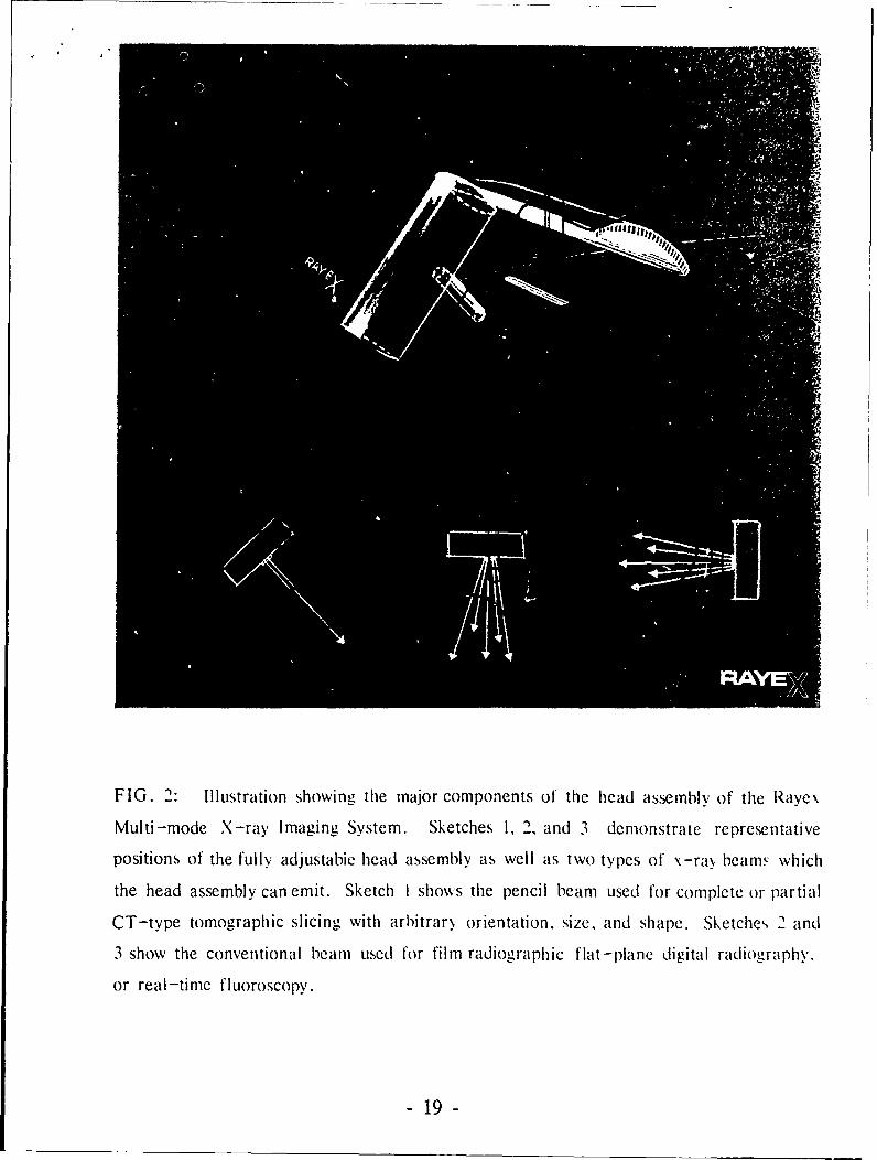
FIG. 2: Illustration showing the major components of the head assembly of the Raye\
Multi-mode X-ray Imaging System. Sketches 1, 2, and 3 demonstrate representative
positions of the fully adjustabie head assembly as well as two types of x-ra. beams which
the head assembly can emit. Sketch I shows the pencil beam used for complete or partial
CT-type tomographic slicing with arbitrar, orientation, size, and shape. Sketches 2 and
3 show the conventional beam used for film radiographic flat-plane digital radiography.
or real-time fluoroscopy.
- 19 -

?-r
FIG. 3: Illustration demonstrating the operation of the' Ra.ve\ Multi -mode X-ra\
Imaging System during Cl -type tornographic slicing. rhe monitor sho\ýs the resultant
CT-type tomographic image of a complete slice. Fhe \-ra> tube and collimator produce
a pencil beam which passes through the patient's bodk\. BackscatterCd radiation is prod-
uced at each point along the line of penetration. Some of this backscattered radiation
enters the slot of the head assembly and is sensed h\ the elements of the detector panel
as shown by the ray diagram. (Only those backscattered \-rays that pass through the
slot are indicated in the figure). Each indi, idual element of the detector panel selectivel\
senses tie x-rays which are backscattered from t gixen point along the pencil beam.
The information ,sensed bh the elements o4 the detector panel is then processed to prod-
uce the resultant image seen on the monitor. Note that the use ol hackscattered radiation
permits one-sided operation and Climinates tile need to; an ll-ra\ sensor on the back side
of the patient. The black star-shaped ohiect represents an embe'dded lorign hod\.
- 20 -
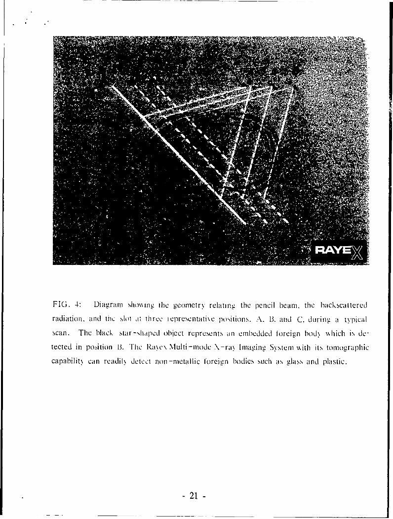
FIG. 4: Diagram shox~ trg tile geomnetrv relating the pencil beami, the backscattered
radiation. and the slot atI th ree ieprese ntaiti \e posýitions. A. 13, and C. during a typical
scan. The black star-shaped object represent~s an emlbedded torcion bod% which Is die-
tected in po~ition 13. The Raw\' Multi -mode N -ra\ I maging Syst em \Nuth its toniographic
capabilit\ can readil\ detect non -metallic foreign bodies such as glass and plastic.
-21-

FIG. 5: Illustration demnonstratino operation of' the Raye\ NiUlti -mode NX-ray Imagzing
System for partial tomnographic slicing. The partial slices ( 1, 2. and 3) are indicated onl
the torso and thier resultinu irnaoes are shown on thle monitors to the riozht. Note that
the. partial slices can be confined (,nk! to the critical regioný ot' interest. The black star -
shaped object represents an embedded foreign bod\.
- 22-

FIG. 0: Illustration shmwing the Ravex Mlulti -mode N -ra\ Imiaging S\ stein positioned
for real -time fluoroscopic imaging. Note that the head asserhlk is emitting a com\entional
beamn. Also note thc mobile imiage intensifier belom the litter. Thie sameI Conlfig uration
can be used to produce a H at-plane digital image. Thec im-age interisiier can also be
replaced by film cassettes for Conventional film radiograph\-
- 23-

Filter
250 kV CollimatorX-ray
Source
-4-
"IF X-ray Beam
Slot
Detector array BK- Camera
D'
Figure 7. Experimental Arrangement for the Slot Camera System
- 24 -

Slot Camerai /,
"Xay detector
detector array I X-ra " .
slot width
I median planeS II/r smloia plate
* object widtA ~II
X-r•ay b amX-ray beam
resolution length
Figure 8. Parameters for Slot Camera Geometry
- 25 -

/ b
X-RayBeam
Slot
Camera
,'Image Plane
Detector Array W
Figure 9. Detector geometry for Slot Camera. Detectors 1 and 2are equivalent to pixels in the image plane correspondingto the volume elements at positions 1 and 2 in the object.
- 26

Figure 10. X-ray detector consisting of plastic detector,light pipe, and photo-multiplier tube.
- 27 -

-09
fo
xz-
Figure 11. Assembly of 20 detector elements withdifferent views to show packing arrangement.
28

al n ru n n rr n n vn--n- t n n n n c
'~r~rtN;
-gg tg .1Y,. nj2:s t!V
* ,v~ 5-&-v"' rm
*4~~r ' t't.Qy- ~.~ly
Q- ,Dr__R_
mg H,7 t&* '4,
~ ' 4 ~~ - .:~.NF,
4, 1 en
~tgs~~-.j
MY )
12 L I
""OldC

100 keV1.0
7-- 7=77-F
_.1
7- 7 --- -
o 20 40-6 -- 8-- 100
Figur 13. Deedne o th X-a detectio
30 -

00
+ C
Cu
1.4'4
cr.4
00
4-0,
0) N: 0
0 0 00
zU13iod ~I-xIoqwN ~AITO>
=310 31

VA Slot aperture
AirspaceIncident X-rays Plsi Shee
S• Plastic Sheet
Repeat pattern"six plastic sheets
Separators
"[•.• 10 cm
9cm
Figure 15. Structure and arrangement of theSpatial Resolution Indicator.
- 32 -
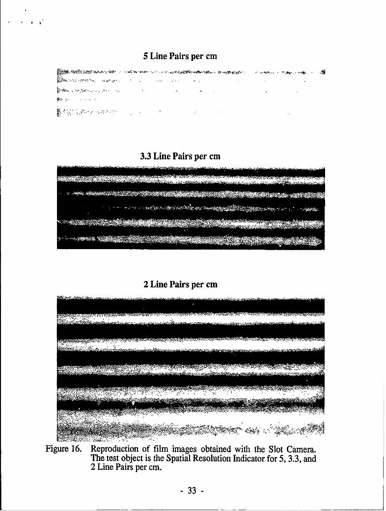
5 Line Pairs per cm
3.3 Line Pairs per cm
2 Line Pairs per cm
Figure 16. Reproduction of film images obtained with the Slot Camera.The test object is the Spatial Resolution Indicator for 5, 3.3, and2 Line Pairs per cm.
- 33 -

120 5 LINE PAIRS PER CM
100
80
60
40-
20-
01 2 3 4 5 6 7 8 9 10 11
120
3.3 LINE PAIRS PER CM100
80
60
40----20
001 2 3 4 5 6 7 8 9 10 11
120 2 LINE PAIRS PER CM
100
80
Normalized 60 ,Counts
40
20 "t • "
1 2 3 4 5 6 7 8 9 10 11Detector Number
Figure 17. Digital outputs from the Slot Camera detectorarray with the Spatial Resolution Indicatorscorresponding to 2, 3.3, and 5 Line Pairs per cm.
- 34 -

- ~FILTRIATION _ _ _ _ _ _ _ _ _ _ _
-OIL
-O- U t
100
I . - -qu it - :XD2---.. w d------
unia-o -K-ntpn pe scod,
-~~ ~ ~ ------ ----- ---
K i vot
_______-_35

SpatialGap Resolution,
Penetration Width, Line PairsDepth, cm mm Per cm
0
1.3 1.6 3.1
2.7 3.0 1.7
4.1 1.6 3.1
4.8 0.8 6.3
5.5 3.M 2.7
6.2 0.8 6.3
7.0 1.6 3.1
7.6 0.8 6.3
8.4 3.0 1.7
9.8 1.6 3.1
11.2• l[ 3.6 1.7
12.8 1.6 3.1
14.2 -3.0 1.7
No Absorber 7.6 cm Lucite Absorber,No Anti-scatter Baffles
Figure 19. Reproduction of film images of a 15 cm long lucite test objectwith different gap widths at different depths. Images arecompared with and without a 7.6 cm lucite absorber interposedbetween the beam axis and the slot camera.
- 36 -

---P:s~z _-.Tr- _
__ . . A- - - ...il _-_m .. .1 0 -------------------- _ra F-
.0
_.'•L • _• t ' ' ' t ,., ."- ,=E .' ,", I ' . . . .
0 2n
Line Pairs per cm
Figure 20. Local body dose at position of beam axis opposite slot aperture (Figure7), as a function of spatial resolution (Line Pairs per cm), for X-ray bodyabsorption thickness of 10 and 20 cm. The solid lines were obtained withthe low efficiency detectors ( vi = 0.007) used in the Phase I program.The dotted lines were obtained with high efficiency detectors ( vj = 1.0)which are proposed for a Phase HI program. The dashed line is theaverage dose per image slice for present CT systems.
-" = -= -&. . . .• . . .. • -- • : -- i t - t = - - = - - -_ • - • - -