ad-a208 810 design guidance for command, control, v the contents of this report are not to be used...
TRANSCRIPT
USACERL TECHNICAL REPORT E-89/10May 1989
Studies in Optimizing HVAC Hardware for C31 FacilitiesUS Army Corpsof EngineersConstruction EngineeringResearch Laboratory "T, LE '
AD-A208 810
Design Guidance for Command, Control,Communications, and Intelligence (C31)Facility Cooling Systems
bySteven A. JenningsV. Alexander MooreRobert T. LorandGlen A. Chamberlin
Design guidance has been developed for cooling systemsin command, control, communications, and intelligence(C31) facilities. This report describes design and equipmentalternatives available with special attention to operation,principal applications, cost, advantages, and disadvantages.The alternatives are evaluated and ranked according to theirability to fulfill each of the following criteria: flexibility inmeeting load redistribution and load expansion, humiditycontrol, particulate matter filtering ability, static electricitycontrol, backup cooling, reliability, lowest cost for shield-ing against electromagnetic pulse (EMP) and related phe-nomena, and lowest life-cycle cost.
3 DTICnELECTEJUN 12 1989D
Approved for public release; distribution is unlimited.
89 6 12 004

V
The contents of this report are not to be used for advertising, publication, orpromotional purposes. Citation of trade names does not constitute anofficial indorsement or approval of the use of such commercial products.The findings of this report are not to be construed as an official Departmentof the Army position, unless so designated by other authorized documents.
DESTROY THIS REPORT WHEN ITIS NO I.ONGER NEEDED
DO NOT RETURN IT TO THE ORIGINA TOR
UNCLASSIFIEDStCuRITY CLASSIPICA"ION OF THIS PAGE
Form Approved
REPORT DOCUMENTATION PAGE ONI 07040,88T E0"ll Dare Jun 30 1986
'' REPORT SECURITY CLASSIFICATION lb RESTRICTIVE MARKINGS
UNCLASSIFIED,a SECURITY CLASSiF,CATION AUTHORITY 3 DISTRIBUTION /AVAILABILITY OF REPORT
Approved for public release;b DECLASS;FCATiON. DOWNGRADING SCHEDULEdirbuon sulitedistribution is unlimited
4 PERFORMING ORGANIZATION REPORT NUMBER(S) 5 MONITORING ORGANIZATION REPORT NuMBER(S)
USACERL TR E-89/10
6a NAME OF PERFORMING ORGANIZATION 6b OFFICE SYMBOL 7a NAME OF MONITORING ORGANIZATIONU.S Army Construction Engr (If applicable)
Research Laboratory CECER-ES
6c ADDRESS (Cjty, State, arid ZIPCode) 7b ADDRESS (City, State, and ZIP Code)
P.O. Box 4005Champaign, IL 61824-4005
8a NAME OF FUNDING. SPONSORNG rSb OFFICE SYMBOL 9 PROCUREMENT INSTRUMENT IDENTIFICATION NUMBER
ORGANiZATtON ( if applicable) Project Order E87870241, "Studies inUSAEHSC ICEHSC-PREP Optimizing Heating, Ventilating, (cont'd)
8c. ADDRESS (City. State, and ZI' Code) 10 SOURCE OF FUNDING NuMBERS
Fort Belvoir, VA 22060 PROGRAM IPROJECT ITASK IWORK UNITELEMENT NO NO N ACCESSION NO
*1 ThTLE (Inciude Security Classification) 3
Design Guidance for Command, Control, Communications, and Intelligence (C I) Facility
Cooling Systems (Unclassified)12 PERSONAL AUTHOR(S)
Jennings, Steven; Moore, V. Alexander: Lorand, Robert: ChamberlinG en - "
13a TYPE OF REPORT 13b TIME COVERED '14 DATE OF REPORT (Year Month, Day) 15 PAGE COUNT
Final IFROM TO I 1989. XayI 11716 SuPPLEMENTARY NOTATON
Coppies are availabel from the National Technical Information Service
Springfield, VA 22161
17 COSATI CODES 18 SUBJECT TERMS (Continue on reverse if necessary and identify by block number)
F,ELD GROUP SUB-GROUP command, control, communications, and intelligence facf3 I cooling and ventilating equipment0 C 31 facilities design guidance
19 ABSTRACT (Continue On reverse of necessary and identify by block number)
Design guidance has been developed for cooling systems in command, control, com-
munications, and intelligence (C 31) facilities. This report describes design and equipment
alternatives available with special attention to operation, principal applications, cost,
advantages, and disadvantages. The alternatives are evaluated and ranked according to
their ability to fulfill each of the following criteria: flexibility in meeting load redistri-
bution and load expansion, humidity control, particulate matter filtering ability, static
electricity control, backup cooling, reliability, lowest cost for shielding against
electromagnetic pulse (EMP) and related phenomena, and lowest life-cycle cost.
20 DiSTRISUTION AVAILABILITY OF ABSTRACT 21 ABSTRACT SECUR, v CLASSFICATION
03 JNCLASSIF ED, UNLIMITED C] SAME AS RPT 0 DT'C USERS Unclassified
22a NAME OF OESPONSiBLE ,NDIVDUAL 2,1b TELEPHONE (include Area Code) 22c OFFICE SYMBOL
Dana Finney (217)352-6511 (ext- 38Q FCFR-TMq"
DD FORM 1473, 84 MAR 81 APR edtion may be used until exhausted SEr. RiTy CLASSIFICATION OF rIS ;'AGE _All other editions are obsolete UNCLASSIFIED

UNCLASSIFIED
Block 9 (cont#d)
and Air-Conditioning (UVAC) for C3I Facilities" dated 8 July,1987.
UNCLAS5! lID

FOREWORD
This research was conducted for the U.S. Army Engineering and Housing SupportCenter (USAEHSC) by the Energy Systems Division (ES) of the U.S. Army ConstructionEngineering Research Laboratory (USACERL) under Project Order E87870241, "Studies inOptimizing Heating, Ventilating and Air-Conditioning (HVAC) Hardware for C 3IFacilities" dated 8 July 1987. The study was prepared for USACERL by Science Applica-tions International Corp. (SAIC), McLean, VA, under delivery order #0001, contract No.DACA 88-88-D-0026. Dr. Harold Hollis, CEHSC-PREP, was the USAEHSC TechnicalMonitor. Glen A. Chamberlin was the USACERL Principal Investigator.
Dr. G. R. Williamson is Chief, USACERL-ES. The technical editor was DanaFinney, USACERL Information Management Office. Robert T. Lorand, V. AlexanderMoore, and Steven A. Jennings are with SAIC. Appreciation is extended to Ray G.McCormack and Michael R. McInerney from the Engineering and Materials Division atUSACERL for assistance with this project.
COL Carl 0. Magnell is Commander and Director of USACERL, and Dr. L. R.Shaffer is Technical Director.
LAccession For
I NT TIIS
SU-1,_".' _)!.,V'nd 10
S I C
t:
3

CONTENTS
Page
DD FORM 1473 1FOREWORD 3LIST OF FIGURES AND TABLES 6
1 INTRODUCTION ........................ . ...................... ..... 91-1. Background 91-2. Objective 91-3. Approach 101-4. Scope 101-5. Ranking Criteria 11
2 AIR DISTRIBUTION SYSTEMS .......... .*......................... 13Section I: GENERAL 13Section I: SYSTEM DESCRIPTION 132-1. Plenums and Ducts 142-2. Diffusers, Grilles, and Registers 222-3. Other Considerations 31Section MI.- SUMMARY EVALUATION 352-4. How To Use the Evaluation Table 352-5. Evaluation Results 36
3 CHILLED LIQUID DISTRIBUTION SYSTEMS ............................... 40Section 1: GENERAL 403-1. System Types 40Section U: SYSTEM DESCRIPTIONS 413-2. System Configurations 413-3. Piping Configurations-Outside the C31 Room 413-4. Piping Configurations-Inside the C 31 Room 453-5. 15-Min Backup Cooling Capacity 503-6. Piping System Components 523-7. Other Considerations 65Section I: SUMMARY EVALUATIONS 673-S. How To Use the Evaluation Table 673-9. Evaluation Results 68
4 AIR-HANDLING SYSTEMS .... ... ........... . .... ........... ....... 72Section I: GENERAL 724-1. Types of Air Handlers 72Section lh SYSTEM DESCRIPTION 734-2. Air Handlers for C3 I Rooms 734-3. Central Station Air-Handling Units 734-4. Chilled-Water Packaged Units 774-5. Self-ContaIned Packaged Units 814-6. Fan Coil Units 844-7. Other Considerations 85Section II: SUMMARY EVALUATION 864-8. How To Use the Evaluation Table 864-9. Evaluation Results 86
4
CONTENTS (Cont'd)
Pap
5 LIQUID CHILLING SYSTEMS ............................................ 91Section I: GENERAL 915-1. Liquid Chiller Types 91Section I: SYSTEM DESCRIPTION 915-2. Classes and Components 915-3. Reciprocating Chillers 925-4. Rotary Screw Chillers 955-5. Centrifugal Chillers 975-6. Absorption Chillers 1005-7. Other Considerations 103Section HI: SUMMARY EVALUATION 1065-8. How To Use the Evaluation Table 1065-9. Evaluation Results 106
6 CONCLUSION ....................................... 11
METRIC CONVERSION TABLE 111
BIBLIOGRAPHY 112
LIST OF ABBREVIATIONS 114
DISTRIBUTION
5

FIGURES
Number Page
2-1 Underfloor Plenum Supply 14
2-2 Ceiling Plenum Supply 17
2-3 Constant-Volume Mixing Box 19
2-4 Perforated Floor Panel 24
2-5 Perforated Ceiling Diffuser 25
2-6 Adjustable Bar Grille 26
2-7 Fixed Bar Grille 26
2-8 Square and Round Louvered Diffusers 27
2-9 Slot Diffusers 29
2-10 Adjustable Air Flow Pattern 29
2-11 Static Pressure Vs. Volume Flow Rate 32
2-12 Honeycomb Waveguide Air Vent Panels 32
2-13 Cell Construction 33
2-14 Honeycomb Waveguide Panel Attached to Primary Shield 34
2-15 Air Flow Characteristics of a Honeycomb Panel 34
3-1 Central Chiller 42
3-2 C 3I Building Chiller 43
3-3 Dedicated C 3I Chiller 44
3-4 Interior C31 Room Piping 46
3-5 Perimeter C31 Room Piping 47
3-6 Chiller Tempering Loop 49
3-7 System for 15-Min Backup Cooling Capacity 51
3-8 Gate Valve 55
3-9 Globe Valve 56
3-10 Angle Valve 57
6

FIGURES (Cont'd)
Number Page
3-11 "Y" Valve 57
3-12 Swing Check Valve 58
3-13 Lift Check Valve 58
3-14 Butterfly Valve 59
3-15 Multiple Pump Piping 61
3-16 Centrifugal Pumps Used in Hydronic Systems 62
3-17 Metallic Pipe Penetration 65
3-18 Dielectric Pipe Penetration 66
4-1 Equipment Arrangement of a Central Air-Handling Unit 73
4-2 Central Air-Handling Unit 74
4-3 Chilled-Water Packaged Unit 78
4-4 Self-Contained Packaged Unit 82
4-5 Fan Coil Unit 85
5-1 Water-Cooled Reciprocating Chiller 92
5-2 Air-Cooled Reciprocating Chiller 93
5-3 Rotary Screw Chiller 95
5-4 Compression Process in a Rotary Screw Chiller 96
5-5 Centrifugal Chiller 98
5-6 Single-Stage Absorption Chiller 101
5-7 Main Components of a Gas Engine-Driven Chiller 104
TABLES
2-1 Summary Evaluation--Air Distribution Systems 36
3-1 Summary Evaluation--Chilled Liquid Distribution Systems 68
4-1 Summary Evaluation--Air-Handling Systems 86
5-1 Summary Evaluation--Liquid Chilling Systems 107
7

DESIGN GUIDANCE FOR COMMAND, CONTROL, COMMUNICATIONS,AND INTELLIGENCE (C31) FACILITY COOLING SYSTEMS
1 INTRODUCTION
1-1. Background
a. Command, control, communications, and intelligence (C 31) facilities often housecomputer and communications equipment, radar systems, printers, disk and tape drives,monitors, and system consoles--all of which generate substantial amounts of heat. Tooptimize performance and ensure continued operation, the environment containing theelectronic equipment must be maintained within stringent temperature and humiditylevels. In addition, the comfort needs of personnel required to operate the equipmentmust be met and airborne particulate matter effectively filtered from entering the C31room airstream. The electronic equipment and personnel must also be protected fromelectromagnetic pulse (EMP) phenomena, biological contamination, and radiation. In theevent of a power failure, a backup system must be available to provide chilled water andcool air to the water- and air-cooled electronic equipment, respectively, for at least 15min.
b. With the rapid advancements in state-of-the-art electronics, existing equipmentwithin C 31 facilities is constantly being replaced by new, efficient, and more powerfulmodels. As a result, electronic equipment within these C 31 facilities is continuallyrelocated to enhance the performance of particular C 31 functions. In addition to equip-ment relocation, the volume of equipment inside a C31 building often increases overtime. The cooling systems used to maintain environmental conditions within individualC 31 rooms must be designed to adapt to these changing circumstances, while still main-taining adequate filtration, EMP protection, and backup.
c. The Department of Defense (DOD) owns and operates many C31 facilities acrossthe nation and abroad, ranging from small computer rooms to large radar facilities. Thediversity of C 31 applications and specialized requirements, coupled with the need forflexibility, has given rise to a large number of different design solutions. For this reason,DOD needs simplified design guidance that addresses the criteria most critical to deci-sions supporting the military mission.
1-2. Objective
The objective of this study is to provide simple, easy-to-use design alternatives for C 3Icooling systems that meet the specific technical criteria of greatest consequence indesign decisions. Part of this objective is to present advantages and disadvantages foreach alternative.
9
1-3. Approach
a. Information for this study was collected from the product literature, manufac-turers, and field operating agencies. (Published sources are listed in the Bibliography.)Subsystem alternatives were evaluated on the basis of:
(1) Operation: physical characteristics and mode of operation for each subsystemalternative. Included is information on common components, control strategies, andperformance.
(2) Principal applications: those for which each subsystem alternative is bestsuited.
(3) Size: the available ranges.
(4) Cost: normalized on the basis of either "per square foot,,* of C 3 I room floorarea, "per cubic foot per minute (CFM)" of air flow, or "per ton" cooling capacity, de-pending on the subsystem.
(5) Advantages/disadvantages: described for each subsystem alternative in var-ious applications.
b. The subsystems were then evaluated according to applicable criteria (listed inSection I of each chapter. Evaluation tables were developed to summarize the results ofthe qualitative ranking procedure used. These results were analyzed to explain whycertain subsystem alternatives ranked higher or lower for particular criteria.
c. When ranking each subsystem alternative, certain assumptions were made regard-ing the system configuration. These assumptions were based on the most common systemconfiguration in which each subsystem alternative is used. The summary evaluation ineach chapter lists these assumptions; it is important to read these sections before view-ing the evaluation tables in order to understand the results in proper context.
1-4. Scope
a. This report is intended to be used by designers as an aid in evaluating the relativemerits of alternative cooling subsystems with respect to specific criteria or designconsiderations. It is not intended to be a C 31 cooling system design manual or hand-book. It is the individual engineer's responsibility to design a system that performs therequired air-conditioning functions effectively in compliance with DOD and other appli-cable codes.
b. The equipment and installation cost estimates given in this report are for compar-ison only and should be used with caution. The estimates do not replace the need toconduct detailed cost estimates that consider locally available resources.
c. The guidelines present information on four main subsystems that comprise allcooling systems: (1) supply air distribution systems, (2) chilled liquid distribution
*Metric conversion factors are listed on p 111.
10
systems, (3) air-handling units, and (4) liquid chilling systems. The rationale for evaluat-ing subsystems and the specific criteria addressed are described below.
1-5. Ranking Criteria
This study evaluated subsystems rather than complete systems to provide the designerwith maximum flexibility in combining subsystem options. The various subsystems areevaluated against a standard set of criteria, not all of which apply in every case. Thespecific criteria addressed for each subsystem are presented in Section I of eachchapter. The interpretation of the evaluation criteria varies by subsystem. The oper-ation and function of different cooling subsystems dictates how they are evaluated underthe various criteria. The standard set of criteria is as follows:
a. Flexibility in Meeting Load Redistribution. This criterion is used to judge thecooling subsystem's ability to accommodate the relocation of electronic equipment (andtherefore the location of concentrated cooling loads) within the C 31 room.
b. Flexibility in Meeting Load Expansion. This criterion addresses the cooling sub-system's ability to handle the increased cooling load resulting from the installation ofadditional electronic equipment.
c. Precise Humidity Control. This criterion addresses the subsystem's ability tocontroi the humidity level in the C 31 room within prescribed limits.
d. Particulate Matter Filtering. This criterion involves the subsystem's ability toprevent the introduction of particulate matter into the C31 room air stream.
e. Static Electricity Control. This criterion addresses the subsystem's ability toprevent the buildup of static electricity within the C 3I room, avoiding possible damage tothe electronic equipment. Static electricity control often is a function of the humiditylevel in the C 3 1 room.
f. Backup Cooling. This criterion is used to assess the need for air- and water-cooledelectronic equipment to have an uninterrupted supply of chilled water. In the event of apower failure, the backup system must supply chilled water to the equipment for at least15 min, in which time the emergency generators can be started and placed in service.
g. Reliability. This criterion addresses the subsystem's ability to provide reliable,low-maintenance operation.
h. Least Cost for EMP Shielding. This criterion is considered in judging the relativecost of protecting EMP shielding when various subsystem alternatives are used.
i. Lowest Life-Cycle Cost. This criterion addresses the total life-cycle cost of thesubsystems, including first cost, energy operating cost, maintenance cost, replacementcost, and any salvage value benefits. It indicates the true owning and operating costs ofeach subsystem alternative.
11
(1) Where indicated, the life-cycle cost analyses were conducted In accordancewith National Bureau of Standards Handbook 135.1 Total life-cycle cost was selected asthe economic measure over other modes of analysis.
(2) National average base-year energy prices and uniform present worth (UPW)factors, adjusted for energy price escalation, were used in the analyses. The UPW fac-tors for determining the present value of future annually recurring (nonfuel) maintenancecosts were based on a 7 percent discount rate.
j. Other Evaluation Areas. Where applicable, other considerations such as nuclear,biological, and chemical (NBC) contamination noise, energy conservation, and spaceutilization efficiency were addressed in the evaluations.
'National Bureau of Standards Handbook 135, Life-Cycle Cost Manual for the Federal
Energy Management Program (December 1980).
12
2 AIR DISTRIBUTION SYSTEMS
Section I: GENERAL
This chapter evaluates design approaches for supply and return air distribution systemsserving electronic equipment rooms. The following criteria are used to evaluate eachsystem component:
1. Flexibility in meeting load redistribution.2. Flexibility in meeting load expansion.3. Precise humidity control.4. Filtering of particulate matter.5. Static electricity control.6. Capacity to provide 15 min of backup cooling.7. Reliability.8. Least cost for EMP shielding.9. Lowest life-cycle cost.
Some criteria do not apply to all components of air distribution systems. In these cases,"N/A" appears in the table displaying the results of the ranking procedure. Componentsof air distribution systems for electronic equipment rooms fall into two maincategories: (1) plenums and ducts, and (2) air-diffusing equipment. Supply air plenumand duct configurations typically used in electronic equipment rooms are described first,in addition to common variations (e.g., variable-air-volume [VAVI boxes and constant-volume [CV] mixing boxes). The common methods of handling return air are then ad-dressed. Finally, air-diffusing equipment used to supply conditioned air to the space, andreturn air to air-handling units, are described. The following air distribution systemcomponents are evaluated in this report:
Plenums and Ducts Diffusers, Grilles, and Registers
Underfloor Plenum Supply Perforated Floor PanelsCeiling Plenum Supply Perforated Ceiling DiffusersOverhead Ducted Supply Grilles and Registers
- VAV Boxes Louvered Ceiling Diffusers- CV Mixing Boxes Linear Diffusers
Free Return Light TroffersCeiling Plenum Return Return Air Inlet CoveringsDucted Return
Section II- SYSTEM DESCRIPTION
Electronic equipment rooms have unique air distribution requirements. The system mustdeliver air in a way that effectively dissipates the concentrated cooling loads of elec-tronic equipment, while providing comfort to occupants working in the area. The systemmust satisfy minimum ventilation for the Introduction of outside air. Also, the air distri-bution system must maintain positive pressure to prevent the introduction of air into theC 31 room from adjacent areas. Frequently, C 3I rooms undergo constant change due tothe relocation, addition, and updating of electronic equipment. The air distributionsystem should be able to adapt to the changing environment.
13

2-1. Plenums and Ducts
As mentioned in Section I above, air distribution systems have two major components.This paragraph describes plenums and ducts, whereas paragraph 2-2 describes air-dif-fusing equipment. The function of plenums and ducts is to transport supply air from theair handler to the air-diffusing equipment and to return air from the return inlets back tothe air handler. The supply and return air circuits can be configured in numerous ways.The methods most often used in C3I rooms are as described below.
a. Underfloor Plenum Supply.
(1) Operation.
(a) Connecting electronic equipment to system consoles, printers, disk drives,monitors, and other peripheral equipment requires large amounts of electric cable. Forthis reason, electronic equipment is usually placed on a false, or raised, floor under whichthe interconnecting cables are concealed. Frequently, the cavity between the buildingfloor and the raised floor is also used as a supply air plenum (Figure 2-1).
(b) The standard raised floor system consists of an understructure and floorpanels. The understructure uses pedestals to support the corners of the floor panels. Theunderstructure for most electronic equipment rooms also has a stringer system in whichthe pedestals are connected by structural members. A stringer understructure provideslateral stability and is available as snap-on or bolted construction.
(ILM CNfI I
AIA IOq MM
.aS( Ir l lt
AIR SUPPLYTI4OUSM PCIPWTED
- 1 4 --
Figure 2-1. Underfloor plenum supply. (Source: American Society of Heating,Refrigerating, and Air-Conditioning Engineers [ASHRAE] Handbook[19871, Chapter 33. Used with permission.)
14

(c) To ensure adequate supply air to the electronic equipment room, a clearanceof 12 in. between the building floor and the raised floor is desired, with 10 in. being theminimum accepted clearance. In electronic equipment rooms that require extensivecabling or large volumes of supply air, additional clearance may be needed.
(d) When the air-handling units serving the underfloor plenum are located withinthe C 3I room, the supply connection to the plenum should be as close as possible to thecenter of the area served. Dividing baffles for zoning in the underfloor plenum may beunnecessary with this configuration, since air flowing through the path of least resistanceresults in a self-zoned system. Air turbulence at the supply connection to the underfloorplenum should be minimized by the use of turning vanes.
(e) If supply air temperatures are low, insulation or vapor barriers may be re-quired on the plenum surfaces. Underfloor plenum surfaces should have a smooth finishand be completely clean and airtight to prevent the introduction of particulate matterinto the air stream.
(2) Principal Applications. The underfloor plenum supply system can be usedwith remote air handlers or, more commonly, with air handlers located within the C3Iroom. Air handlers located within the C 31 room may be the chilled-water type served bya liquid chilling system or may be self-contained, packaged, direct-expansion (DX)units. According to several raised floor system manufacturers, 95 percent of all com-puter rooms use underfloor plenum supply systems.
(3) Sizes. Both the standard and perforated floor panels measure 24 by 24 in. Atypical perforated floor panel has 25 percent free area (air passage area divided by totalpanel area) and can handle 550 to 1400 CFM, depending on air velocity, static pressure,and the presence of a volume control damper.
(4) Cost. A typical budget figure for a raised floor system not used as a plenumis $8/sq ft. This cost includes the raised floor understructure, standard floor panels, andinstallation (including contractor's overhead and profit). A perforated floor panel aver-ages $20 more in cost than a standard floor panel. In most applications, an underfloorplenum supply system has a premium cost of 1 to 3 percent ($0.08 to $0.24/sq ft) morethan a raised floor not used as a plenum. Thus, if the C31 room has or is designed to havea :aised floor, the additional cost of using it as an underfloor plenum is between $0.08and $0.24/sq ft. If the C 31 room does not already have a raised floor, the underfloorplenum costs between $8.08 and $8.24/sq ft. It should be noted that these costs do notinclude EMP protection. The principles and costs of EMP protection for air distributionsystems are addressed in paragraph 2-3 below.
(5) Advantages. Since most electronic equipment rooms use a raised floorsystem, the underfloor plenum supply system can be incorporated at a low additionalcost. Perforated floor panels are usually used with the underfloor plenum, providing goodflexibility in accommodating the constant relocation of equipment experienced in today'sC31 rooms. By simply exchanging standard floor panels with perforated floor panels, theair distribution pattern can be modified to satisfy the changing locations of concentratedcooling loads.
(b) If the air handlers serving the underfloor plenum are located within the C 3Iroom, the air distribution system can handle load expansion by accommodating additionalair handlers. With this configuration, air handlers can be added without interrupting theoperation of existing air handlers. The use of multiple air handlers provides the redun-dancy required by C31 rooms. In critical C 31 facility applications, a rule of thumb for
15
redundancy often cited is that sometimes referred to as "N+2." This convention statesthat, for mission-critical equipment, two additional units should be provided. If one unitfails while another is down for maintenance, the third unit can satisfy mission require-ments. If the mission is less critical, one extra unit (100 percent redundancy) may beadequate. Three factors dictate the level of redundancy required: (1) critical nature ofthe mission, (2) equipment reliability, and (3) equipment cost. It is the design engineer'sresponsibility to assess these three factors and determine the level of redundancy re-quired for a specific facility.
(c) Controls in the air handler are primarily responsible for regulating the C 3Iroom air temperature and humidity. However, the air distribution system affects thevariation of air temperature and humidity within the space. The perforated floor panelsusually used with the underfloor plenum supply system have a higher entrainment ratio(total room air divided by discharge air) near the point of discharge than many types ofdiffusers, grilles, and registers. The higher the entrainment ratio, the faster differencesin temperature and humidity between room air and discharge air are equalized. Thismeans that perforated floor panels can be located closer to electronic equipment withless fear of condensation inside the equipment than with many other types of air-dif-fusing equipment.
(d) The raised floor systems that comprise an underfloor plenum are availablewith antistatic and conductive coatings to control the discharge of static electricity toelectronic equipment. In addition, the stringer system used with raised floors in mostC 3U rooms provides an effective path for the dissipation of static electricity.
(7) Disadvantages.
(a) Underfloor plenums must have adequate clearance to deliver the requiredvolume of air to the C 3I room. If the cabling between electronic equipment is extensive,raised floor heights of up to 36 in. may be needed to provide the minimum plenum clear-ance. If the floor-to-ceiling height in the room is limited, the use of an underfloorplenum may be precluded. While locating the air handlers within the space providesflexibility in meeting load expansion, the air handlers occupy space that is often quitevaluable in the C 3I room. If the underfloor plenum is served by a remotely located airhandler, load expansion must be accommodated by more traditional methods. The vol-ume of air discharged by the air handler must be increased by increasing fan speed. If asubstantial cooling load is added, the cooling coil of the air handler may have to bereplaced with one of increased capacity. Both of these methods require that the airhandler be shut down for modification.
(b) If properly constructed, underfloor plenums should allow minimal entrain-ment of particulates into the discharge air stream. However, underfloor plenums aremore likely to accumulate dust and dirt than ceiling plenums and ducted supply systems.
(c) The panels in raised floor systems are designed to withstand rolling loadsof up to 2000 lb and dynamic impact loads of up to 200 lb. The panels are constructed tosupport concentrated static loads of up to 2000 lb with a 0.08-in. top deflection; theyhave ultimate load ratings of up to 6000 lb. Despite the structural integrity shown bythese static and dynamic load ratings, as well as the durable floor coverings available--both of which suggest that raised floor systems generally have good reliability--wear andtear are more of a concern for underfloor plenum supply systems than for ceiling plenumor ducted supply systems.
16

b. Ceiling Plenum Supply.
(1) Operation.
(a) Similar to the underfloor plenum supply system, this system uses the cavitybetween the building roof and the ceiling of the electronic equipment room as a supplyair plenum. Supply air from the ceiling plenum flows through perforated ceiling panels tothe C3I room. Ceiling plenum supply systems are not considered to be quite as flexibleas underfloor systems in handling load expansion since they are typically served by re-motely located air handlers, which require upgrading to increase cooling capacity.
(b) Distribution ductwork is sometimes used with a ceiling plenum to equalizethe air distribution throughout the plenum (Figure 2-2).
(2) Principal Applications. Ceiling plenums are typically used with remotelylocated air handlers. If the return air also passes through the plenum, return air duct-work must be installed, as shown in Figure 2-2.
(3) Sizes. Ceiling plenums can be designed to handle a wide range of air volumeflow rates. The combination of the plenum size, the size of the duct serving the plenum,and the CFM rating of the air handler dictates the maximum flow rate possible. Themaximum acceptable noise rating of the air-diffusing equipment also impacts allowableair flow rates.
(4) Cost. A typical budget figure for a suspended ceiling is approximately $3/sqft. This cost includes acoustic ceiling panels, T-bar carrier channel suspension system,and installation (including contractor's overhead and profit). The additional cost ofinstalling perforated ceiling diffusers increases the budget figure by about 2 percent($0.06/sq ft). If distribution ductwork is used, the installed cost approaches that of anoverhead ducted system. Thus, if the C3 I room already has a suspended ceiling, theadditional cost of using it as a ceiling plenum is about $0.06/sq ft. If the room does nothave a suspended ceiling, the cost of a ceiling plenum is about $3.06/sq ft. It should benoted that these costs do not include EMP protection. The principles and costs of EMPprotection for air distribution systems are addressed in paragraph 2-3 below.
.- suPPLY TO P..EMN M (SHOuW CM )
RETURN WCOMICIOW couns RETURNW(SHW DUCYEO 7 REGM NISTER
HROWN CIIPAEOWSEW PLOLO R . 0-11
FIgure 2-2. Ceiling plenum supply. (Source: ASHRAE Handbook [1987], Chapter
33. Used with permission.)
17

(5) Advantages. Ceiling plenum supply systems have many of the same attributesof the underfloor plenum supply systems. Load redistribution within the C 3I room can behandled easily by relocating the perforated ceiling diffusers. Similar to the underfloorplenum, the ceiling plenum must have proper clearance to provide adequate air flow tothe C 3I room. However, with the ceiling plenum, no allowance for cabling is necessary.The ceiling plenum is also more likely to stay clean than an underfloor plenum. In addi-tion, the installed cost of a ceiling plenum supply system is less than that of an under-floor plenum supply system.
(6) Disadvantages. Since ceiling plenums are typically served by remotely locatedair handlers, load expansion must be accommodated by upgrading the air handler asdescribed above. In most cases, this work would require an interruption of air flow to theplenum. Also, in some cases, supply air must flow up through the electronic equipment.This requirement is better satisfied with an underfloor plenum supply system.
c. Overhead Ducted Supply.
(1) Operation. In limited applications, electronic equipment rooms may be sup-plied by overhead ducted distribution systems like those used in most heating, ventila-tion, and air-conditioning (HVAC) systems. Overhead ducted supply systems have littleflexibility for handling load redistribution or expansion due to the difficulty in relocatingair outlets in C 31 rooms with continuous duty requirements. Flexible ducting can be usedto increase the ability to handle load redistribution. However, the length of flexible ductruns is normally limited to 6 ft or less due to the high pressure loss associated withflexible ducting that incorporates steel springs. When cooling loads are high, overheaddiffusers may cause drafts.
(2) Principal Applications. Overhead ducted supply systems are restricted toapplications where large volumes of supply air are not needed and relocation of elec-tronic equipment is not anticipated. Typically, the overhead ducted supply system isserved by a remotely located air handler that introduces fresh air for occupants in thespace and for positive pressurization.
(3) Sizes. Overhead ducted supply systems can be designed to handle a wide rangeof air volume flow rates experienced in C 3I rooms.
(4) Cost. For galvanized steel ductwork, the material cost ranges from $0.70 to$2.50/sq ft. Labor, overhead, and profit bring the installed cost to a range of $1.45 to$4.00/sq ft. The use of flexible ducting reduces these costs some 20 percent. Again,these costs do not include EMP protection. The principles and costs of EMP protectionfor air distribution systems are addressed in paragraph 2-3.
(5) Advantages. An overhead ducted supply system will stay cleaner than eitherthe underfloor or ceiling plenum. Ducted supply systems have a proven track record ofreliability.
(6) Disadvantages. Overhead ducted supply systems are restricted to applicationsnot requiring large volumes of supply air or flexibility in meeting load redistribution orexpansion. The installed cost of an overhead ducted supply system is more than eitherthe underfloor or ceiling plenum system, assuming that the C3 I room already has a raisedfloor or suspended ceiling.
18
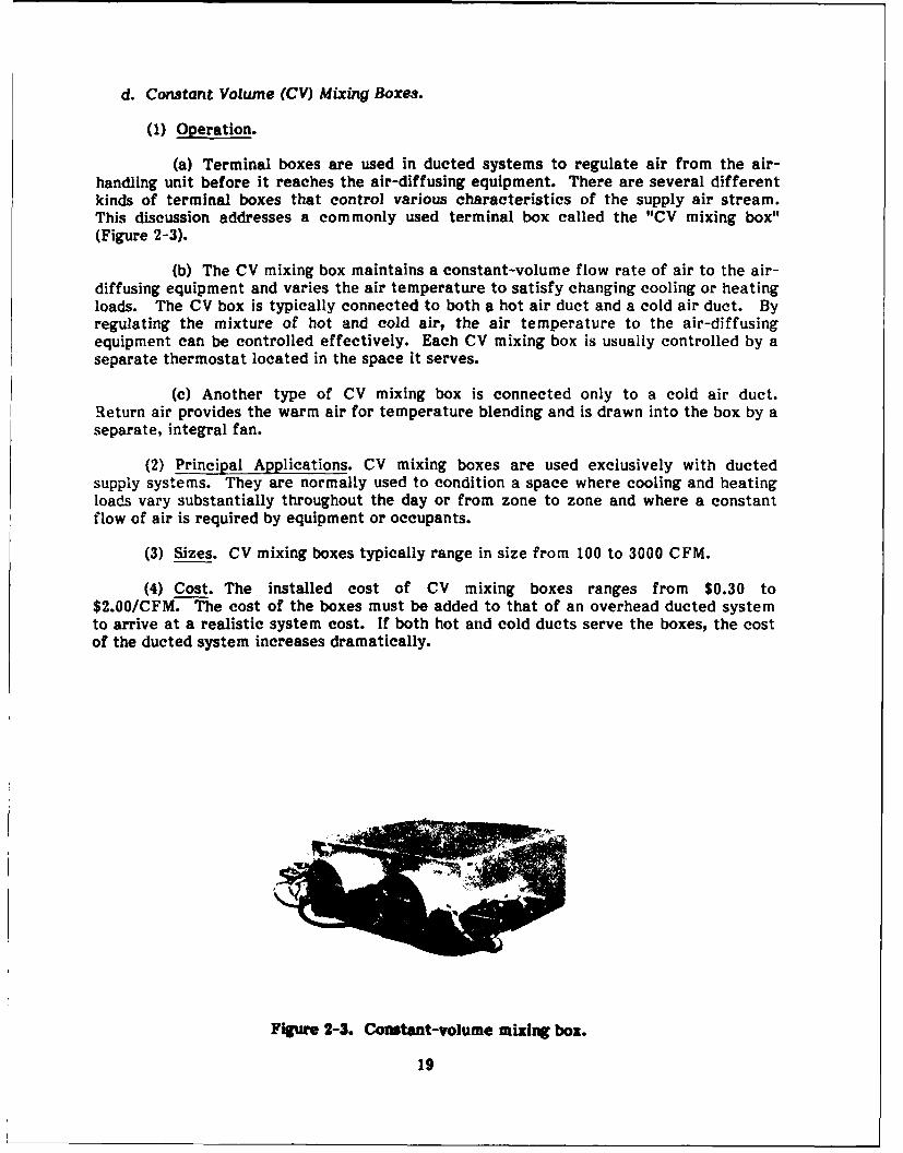
d. Constant Volume (CV) Mixing Boxes.
(1) Operation.
(a) Terminal boxes are used in ducted systems to regulate air from the air-handling unit before it reaches the air-diffusing equipment. There are several differentkinds of terminal boxes that control various characteristics of the supply air stream.This discussion addresses a commonly used terminal box called the "CV mixing box"(Figure 2-3).
(b) The CV mixing box maintains a constant-volume flow rate of air to the air-diffusing equipment and varies the air temperature to satisfy changing cooling or heatingloads. The CV box is typically connected to both a hot air duct and a cold air duct. Byregulating the mixture of hot and cold air, the air temperature to the air-diffusingequipment can be controlled effectively. Each CV mixing box is usuaily controlled by aseparate thermostat located in the space it serves.
(c) Another type of CV mixing box is connected only to a cold air duct.Return air provides the warm air for temperature blending and is drawn into the box by aseparate, integral fan.
(2) Principal Applications. CV mixing boxes are used exclusively with ductedsupply systems. They are normally used to condition a space where cooling and heatingloads vary substantially throughout the day or from zone to zone and where a constantflow of air is required by equipment or occupants.
(3) Sizes. CV mixing boxes typically range in size from 100 to 3000 CFM.
(4) Cost. The installed cost of CV mixing boxes ranges from $0.30 to$2.00/CFM. The cost of the boxes must be added to that of an overhead ducted systemto arrive at a realistic system cost. If both hot and cold ducts serve the boxes, the costof the ducted system increases dramatically.
Figure 2-3. Constant-volume mixing box.
19
(5) Advantages. CV mixing boxes are appropriate when the cooling and heatingloads vary significantly throughout the day or from zone to zone and when a constantflow of air is required by equipment or occupants. CV mixing boxes increase the abilityof a ducted supply system to accommodate the relocation and expansion of load withinthe C 3I room.
(6) Disadvantages. In addition to the high cost of materials and installation, asupply system that uses CV mixing boxes is inherently wasteful from an energy stand-point. The energy used to heat and cool air is wasted at the box when the two airstreams are mixed. Furthermore, C3 I rooms typically have a constant cooling load,negating the benefit of the CV box in handling varied loads.
e. Variable-Air Volume Boxes.
(1) Operation. Another variation of the standard overhead ducted supply systemuses terminal boxes similar in appearance to CV mixing boxes. Unlike the CV mixingbox, the VAV box regulates the volume of air supplied to the air-diffusing equipmentrather than the temperature. Each VAV box reads the space temperature sensed by adedicated thermostat and adjusts the volume flow rate of constant-temperature air basedon the need for cooling. When the cooling load is high, the VAV box delivers the maxi-mum CFM of cool air to the air-diffusing equipment. When the cooling load subsides, thevolume of air is reduced.
(2) Principal Applications. VAV boxes are used exclusively with ducted systems.Like the CV mixing boxes, they are used to condition spaces where the cooling or heatingload varies throughout the day or from zone to zone.
(3) Sizes. VAV boxes are available with air flows ranging from 100 to 3000 CFM.
(4) Cost. VAV boxes' installed cost ranges from $0.20 to $1.75/CFM. The cost ofthe boxes must be added to that of an overhead ducted system to obtain a realisticestimate of system cost.
(5) Advantages. VAV mixing boxes are appropriate when the cooling or heatingloads vary significantly throughout the day or from zone to zone. A VAV system in-creases the ability of a ducted supply system to accommodate the relocation and expan-sion of load within the C3I room. A VAV system matches the fan load to the coolingload. In this way, energy consumption for air distribution is optimized.
(6) Disadvantages. Although VAV boxes increase the flexibility of a ducted supplysystem to handle the relocation or addition of electronic equipment in a C 3I room, theadded cost to the standard ducted system is considerable.
f. Free Return.
(1) Operation. When the air handler is located within the electronic equipmentroom, return air can be drawn directly back into the air handler, eliminating the need forreturn air plenums or ducts. Such a configuration is called a "free return system" and isshown in Figure 2-1. With a free return system, the air handler should be located nearthe concentrated cooling loads. Outside air is not introduced and mixed with return airin a free return configuration. It must be introduced into the C3 I room by a separatesystem (such as a central station air handler) to satisfy minimum ventilation require-ments and maintain positive pressure within the electronic equipment room.
20

(2) Principal Applications. A free return system can be used only in applicationswhere the air handler is located within the C3 I room, such as with an underfloor plenumsupply system, since return air is drawn directly from the room into the suction side ofthe air handler.
(3) Sizes. The air volume flow rates achievable with a free return system aresolely dependent on the supply CFM of the air handlers and the static and velocity pres-sures of the air-diffusing equipment.
(4) Cost. Since there are no plenums, ducts, grilles, or registers associated with afree return system, direct material and labor costs are minimal. However, the cost ofthe C3 I room floor space occupied by the air handlers must be taken into account. Also,if not already present, the cost of a separate system to introduce and filter outside airfor minimum ventilation and positive pressurization must be considered in estimating thecost of a free return system.
(5) Advantages. The free return system is the most flexible and least expensiveof the return systems evaluated. Load redistribution and expansion are automaticallyaccommodated by the number and location of air handlers within the C 31 room.
(6) Disadvantages. The free return system does carry an indirect cost in that theair handlers must be located within the C 3 I room, where space is often limited. Specialprovisions are necessary for introducing outside air to the C 3 1 room.
g. Ceiling Plenum Return.
(1) Operation. Similar to the ceiling plenum supply system, a ceiling plenumreturn system uses the cavity between the building roof and the ceiling of the C I roomas a return air plenum. With this arrangement, heat from the electronic equipment, aswell as some of the heat from the lights and people, is drawn into the ceiling plenum.Frequently, air is returned to air handlers located within the C 3 1 room through ductcollars.
(2) Principal Applications. The ceiling plenum return system can be used withremotely located air handlers or with air handlers located within the C 31 room. With thelatter configuration, return air often flows from the ceiling plenum through a duct collarto the air handler, where it is conditioned and discharged to an underfloor plenum supply.
(3) Sizes. The air volume flow rates achievable with a ceiling plenum returnsystem depend on the size and quantity of return air inlets and on the supply CFM of theair handler.
(4) Cost. If the air handlers are located within the C 3 I room, a ceiling plenumreturn system has an incrementai material cost of about $0.02/sq ft more than that of astandard suspended ceiling. The installed cost is approximately $0.03/sq ft. If ductworkis required to return air to a remotely located air handler, the installed cost is about 60percent more than that for a standard suspended ceiling.
(5) Advantages.
(a) Ceiling plenum return systems provide good flexibility in accommodatingthe relocation of electronic equipment within the C3 I room. Perforated return panelscan be interchanged with standard ceiling panels to easily adapt the return air distri-bution system to changing equipment locations.
21

(b) Ceiling plenum return systems are frequently used in conjunction with theunderfloor plenum supply system served by air handlers located within the C3 I room. Airflows from the ceiling plenum, through duct collars, and back to the air handler, where itis conditioned and fed to the underfloor plenum. With this configuration, load expansiamis handled in the same way as with the underfloor plenum supply: by installing additionalair handlers.
(6) Disadvantages. While locating the air handler within the C31 room offersflexibility for the ceiling plenum return system, the air handlers occupy space that isoften limited. If the air handler is located outside the electronic equipment room, loadexpansion becomes a concern. Also, the plenum may not be airtight and may draw un-wanted air from adjacent areas.
h. Ducted Return.
(1) Operation. In rooms where a ceiling plenum or free return system is notpractical, a ducted return system can be used. Return air is drawn from the C31 room,through the return inlets, and transported back to the air handler through duetwork.
(2) Principal Applications. The ducted return system is usually used when the airhandler is remotely located from the C31 room; however, ceiling-hung fan coil unitslocated inside the C31 room sometimes use a ducted supply and return. A ducted returnsystem can be used with the ceiling plenum or overhead ducted supply systems.
(3) Sizes. Ducted return systems can be designed to handle a wide range of airvolume flow rates experienced in C 31 rooms.
(4) Cost. The installed cost of the ducted return system is relatively high com-pared with the ceiling plenum and free return systems. Even with the lower cost ofreturn grilles versus supply diffusers, the cost of a ducted return system approaches thatof an overhead ducted supply system.
(5) Advantages. In cases for which a ceiling plenum return system is not airtightand draws unwanted air from adjacent areas, a ducted return system can be used withgood results. A ducted return system is also well suited for applications that require 100percent outside air. When used for this purpose, the ducted return becomes an exhaustsystem.
(6) Disadvantages. Return inlets should be placed near areas of concentratedheat gain. When electronic equipment is redistributed within the C 31 room, the returninlets should be relocated. With a ducted return system, relocating the return Inletsrequires the demolition of existing ductwork and the installation of new ductwork. Thisrequirement makes the ducted return system inflexible in meeting the needs of loadredistribution. In addition, the air handler must sometimes be shut down during ductmodifications; however, careful design and placement of dampers may allow Isolation ofthe duct branches to be modified.
2-2. Diffusers, Grilles, and Registers
a. General.
(1) Supply air is usually discharged at velocities much greater than that accept-able to occupants in the space. Also, in a C 3[ room, supply air discharge temperatures
22

are normally below that of the room air temperature. Thus, a well designed air distribu-tion system must entrain room air into the discharge air stream outside the area ofoccupancy and C3I equipment air intakes to reduce air velocity and temperature dif-ferences to levels acceptable to both occupants and equipment. Failure of the distri-bution system to accomplish this condition can result in occupant discomfort and possibleequipment damage (if air supplied to equipment inlets is below the dew point).
(2) Air-diffusing equipment is normally divided into three main categories:diffusers, grilles, and registers. A diffuser is an outlet that discharges supply air invarious directions and planes. A grille is simply a covering for any opening through whichair flows. A register is a grille equipped with a volume control damper. Outlets havebeen classified according to their location and air direction/plane geometry. Air-dif-fusing equipment is also categorized by air direction/plane geometry, in addition tophysical characteristics.
(3) The location and selection of supply outlets are dictated by the location ofheat-producing electronic equipment. The localized heat gain associated with C 31equipment can be handled by directing cool air toward the equipment or by placing returngrilles near the equipment. The latter is more efficient since heat is expelled at thesource instead of being dissipated into the conditioned space. The return air should betaken from as high a point as possible to take advantage of thermal stratification.
(4) Depending on the size of the air-diffusing equipment and the air velocity inthe plenum or duct, each type of diffuser, grille, and register has a different noise cri-teria level. Recommended noise criteria levels are generally stated according to thefunction of the space. A category is not normally listed for C3I rooms, but the criterialisted for tabulation and computation areas of general office buildings approximate theconditions found in most C3I rooms. The recommended maximum noise levels for thesespaces range from 40 to 60 dB.
(5) Most air-diffusing equipment is designed to provide occupant comfort in anormal office environment. Because of the unique conditions in a C31 room, a com-promise must be made between occupant comfort and the cooling requirements of elec-tronic equipment. For this reason, not all air-diffusing equipment is suitable for use inC 31 rooms.
b. Perforated Floor Panels.
(1) Operation.
(a) A common diffuser used in C JI rooms with raised floors is the perforatedfloor panel shown in Figure 2-4. As its name implies, this diffuser is a raised floor panelinto which many holes have been drilled to serve as the air passages. The perforatedfloor panels are interchangeable with the standard panels in a typical raised floor. Thisfeature allows easy modification of supply air distribution to accommodate the reloca-tion or addition of electronic equipment. Because they mount flush with the raised floor,perforated floor panels are ideal for use in normal traffic areas.
23

Figure 2-4. Perforated floor panel.
(b) Though the free area and performance vary, perforated floor panels gen-erally have a high entrainment ratio (total air divided by discharge air) near the point ofdischarge compared with standard grilles and registers. Because of the relatively highmixture of room air with discharge air, perforated floor panels can be placed closer toelectronic equipment than registers or grilles with less fear of delivering air that isbelow the dew point.
(2) Principal Applications. Perforated floor panels are used exclusively withraised floors. They are the air-diffusing ,equipment most often selected for underfloorplenum supply systems.
(3) Sizes. Perforated floor panels are available with free area ratios (air passagearea over total panel area) of 25 to 50 percent. The panels are designed to handle airflows in the range of 550 to 1400 CFM.
(4) Cost. Depending on whether particle board or metal is specified and thequantity ordered, perforated floor panels cost approximately $0.04/CFM. The installedcost runs about $0.05/CFM.
(5) Advantages. As mentioned in the evaluation of underfloor plenum supplysystems, perforated floor panels provide good flexibility in accommodating load redistri-bution and expansion. Because they are interchangeable with standard raised floorpanels, perforated panels can be added or relocated easily. Their high entrainment ratioquickly equalizes differences in temperature and humidity between room air and dis-charge air.
(b) As with standard raised floor panels, perforated floor panels are availablewith antistatic and conductive coverings. The installed cost per CFM of perforated floorpanels is among the lowest of the air-diffusing equipment evaluated.
(6) Disadvantages. As mentioned in describing the underfloor plenum supplysystem, perforated floor panels typically discharge air supplied by air handlers locatedwithin the C3 I room. However, floor space In C I rooms is often limited. Also, the airflow of the perforated floor panel could be obstructed by improper placement of furni-ture or equipment.
c. Perforated Ceiling Diffusers.
(1) Operation. One of the most commonly used ceiling diffusers is the perforateddiffuser. These diffusers are available with fixed or adjustable air patterns(Figure 2-5). The perforated faces are easily removed to provide access to the patterndeflectors and dampers. Some perforated ceiling diffusers consist of only the perforated
24
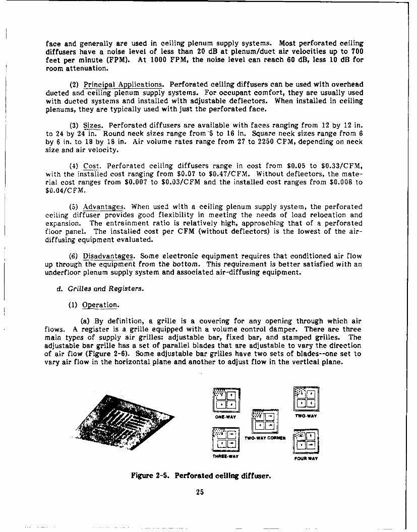
face and generally are used in ceiling plenum supply systems. Most perforated ceilingdiffusers have a noise level of less than 20 dB at plenum/duct air velocities up to 700feet per minute (FPM). At 1000 FPM, the noise level can reach 60 dB, less 10 dB forroom attenuation.
(2) Principal Applications. Perforated ceiling diffusers can be used with overheadducted and ceiling plenum supply systems. For occupant comfort, they are usually usedwith ducted systems and installed with adjustable deflectors. When installed in ceilingplenums, they are typically used with just the perforated face.
(3) Sizes. Perforated diffusers are available with faces ranging from 12 by 12 in.to 24 by 24 in. Round neck sizes range from 5 to 16 in. Square neck sizes range from 6by 6 in. to 18 by 18 in. Air volume rates range from 27 to 2250 CFM, depending on necksize and air velocity.
(4) Cost. Perforated ceiling diffusers range in cost from $0.05 to $0.33/CFM,with the installed cost ranging from $0.07 to $0.47/CFM. Without deflectors, the mate-rial cost ranges from $0.007 to $0.03/CFM and the installed cost ranges from $0.008 to$0.04/CFM.
(5) Advantages. When used with a ceiling plenum supply system, the perforatedceiling diffuser provides good flexibility in meeting the needs of load relocation andexpansion. The entrainment ratio is relatively high, approaching that of a perforatedfioor panel. The installed cost per CFM (without deflectors) is the lowest of the air-diffusing equipment evaluated.
(6) Disadvantages. Some electronic equipment requires that conditioned air flowup through the equipment from the bottom. This requirement is better satisfied with anunderfloor plenum supply system and associated air-diffusing equipment.
d. Grilles and Registers.
(1) Operation.
(a) By definition, a grille is a covering for any opening through which airflows. A register is a grille equipped with a volume control damper. There are threemain types of supply air grilles: adjustable bar, fixed bar, and stamped grilles. Theadjustable bar grille has a set of parallel blades that are adjustable to vary the directionof air flow (Figure 2-6). Some adjustable bar grilles have two sets of blades--one set tovary air flow in the horizontal plane and another to adjust flow in the vertical plane.
ONE-WAY TWO.WAY
TWO-WAY CORNER
THREE-WAY FOUR WAY
Figure 2-5. Perforated ceiling diffuser.
25
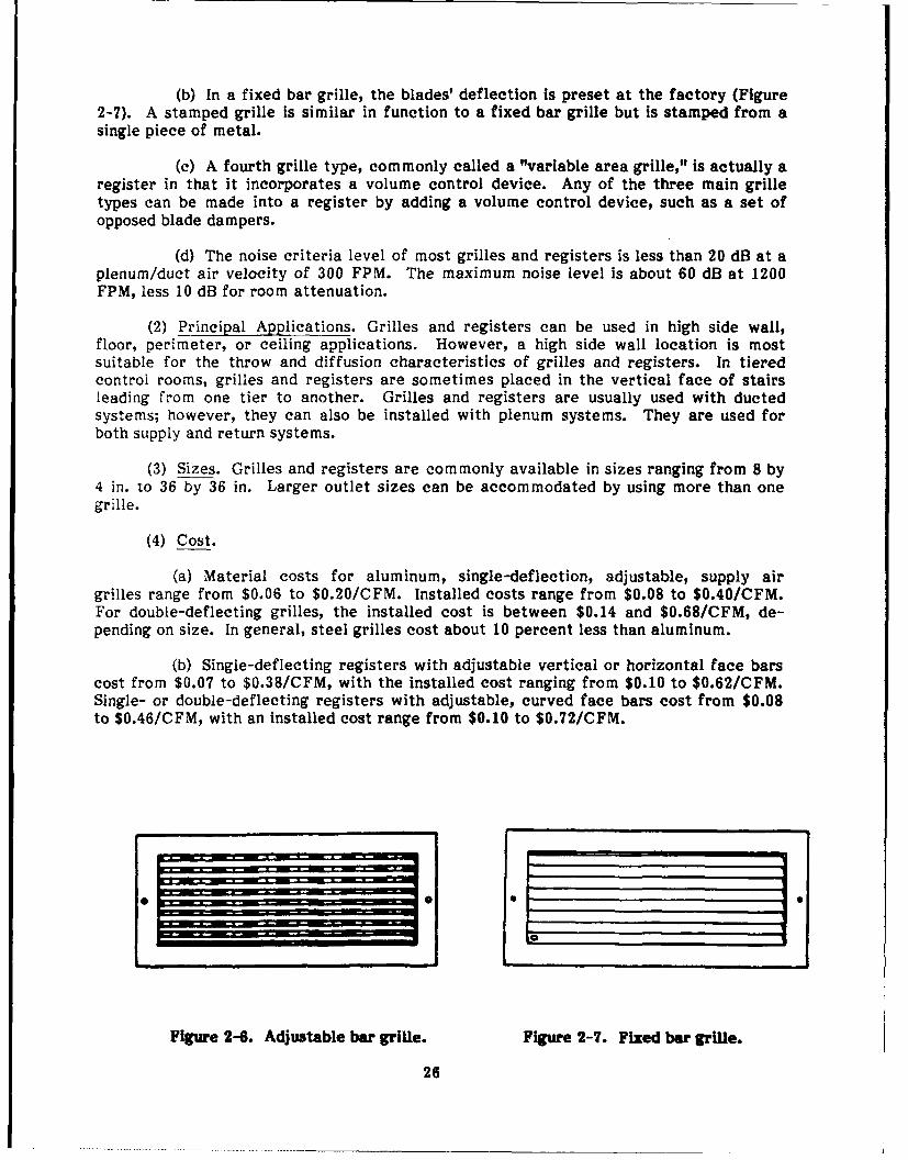
(b) In a fixed bar grille, the blades' deflection is preset at the factory (Figure2-7). A stamped grille is similar in function to a fixed bar grille but is stamped from asingle piece of metal.
(c) A fourth grille type, commonly called a "variable area grille," is actually aregister in that it incorporates a volume control device. Any of the three main grilletypes can be made into a register by adding a volume control device, such as a set ofopposed blade dampers.
(d) The noise criteria level of most grilles and registers is less than 20 dB at aplenum/duct air velocity of 300 FPM. The maximum noise level is about 60 dB at 1200FPM, less 10 dB for room attenuation.
(2) Principal Applications. Grilles and registers can be used in high side wall,floor, perimeter, or ceiling applications. However, a high side wall location is mostsuitable for the throw and diffusion characteristics of grilles and registers. In tieredcontrol rooms, grilles and registers are sometimes placed in the vertical face of stairsleading from one tier to another. Grilles and registers are usually used with ductedsystems; however, they can also be installed with plenum systems. They are used forboth supply and return systems.
(3) Sizes. Grilles and registers are commonly available in sizes ranging from 8 by4 in. to 36 by 36 in. Larger outlet sizes can be accommodated by using more than onegrille.
(4) Cost.
(a) Material costs for aluminum, single-deflection, adjustable, supply airgrilles range from $0.06 to $0.20/CFM. Installed costs range from $0.08 to $0.40/CFM.For double-deflecting grilles, the installed cost is between $0.14 and $0.68/CFM, de-pending on size. In general, steel grilles cost about 10 percent less than aluminum.
(b) Single-deflecting registers with adjustable vertical or horizontal face barscost from $0.07 to $0.38/CFM, with the installed cost ranging from $0.10 to $0.62/CFM.Single- or double-deflecting registers with adjustable, curved face bars cost from $0.08to $0.46/CFM, with an installed cost range from $0.10 to $0.72/CFM.
{0Figure 2-6. Adjustable bar grille. Figure 2-7. Fixed bar grille.
26

(5) Advantages. Grilles and registers are occasionally mounted in raised floors toprovide a more directional air flow pattern than is possible with perforated floor panels.If the grille or register is mounted in a single floor panel, its flexibility for relocation isgreatly increased. In terms of lowest installed cost per CFM, grilles and registers aresecond only to perforated ceiling diffusers and perforated floor panels.
(6) Disadvantages. In general, grilles and registers are more suitable for comfortapplications than for conditioning electronic equipment. Grilles and registers are de-signed to be used primarily with ducted systems. This constraint reduces their flexibilityin handling load redistribution and expansion.
e. Louvered Ceiling Diffusers.
(1) Operation. One of the most basic types of ceiling diffusers is the louvereddiffuser. It consists of a set of concentric square or circular louvers that direct the airflow pattern (Figure 2-8). The concentric louvers are sometimes arranged flush with thesurrounding ceiling, though some have a "stepped down" configuration that protrudesbelow the ceiling surface.
(2) Principal Applications. The louvered ceiling diffusers used in most buildingsprovide an air pattern parallel to the ceiling. The parallel pattern provides good mixingof the incoming cooled air with the warm air near the ceiling. Thus, the air movingaround the room has adequate velocity and the temperature has been equalized. Ceilingdiffusers with a perpendicular pattern are effective for dissipating concentrated coolingloads, such as those from electronic equipment. Louvered ceiling diffusers are typicallyused in ducted systems to provide comfort to occupants in the space.
(3) Sizes.
(a) Louvered ceiling diffusers are available in many different sizes. An ex-ample of a smaller size is a louvered diffuser with a 12 by 12 in. louvered area, 5-in.neck, total pressure drop of 0.04 to 0.41 in. of water (depending on air velocity), and arange of 54 to 190 CFM.
(b) The larger sizes feature a 24 by 24 in. louvered area, 14-in. neck, totalpressure drop of 0.011 to 0.21 in. of water, and air volume rate ranging from 428 to 1500CFM.
Awl
Figure 2-8. Square and round louvered diffusers.
27
(4) Cost. Rectangular louvered ceiling diffusers range in cost from $0.48 to$0.96/CFM, with an installed cost ranging from $0.74 to $1.28/CFM.
(5) Advantages. Louvered diffusers provide a good surface effect with the ceiling(i.e., discharge air tends to flow in the parallel plane close to the ceiling). Diffusers witha good surface effect are appropriate for conditioning occupant areas.
(6) Disadvantages. Louvered ceiling diffusers, like most ceiling diffusers, aredesigned to be used with ducted systems and to provide human comfort; therefore, theirflexibility and suitability for C 3I room applications are limited. The installed cost perCFM of the louvered ceiling diffuser is relatively high when compared with the other air-diffusing equipment evaluated.
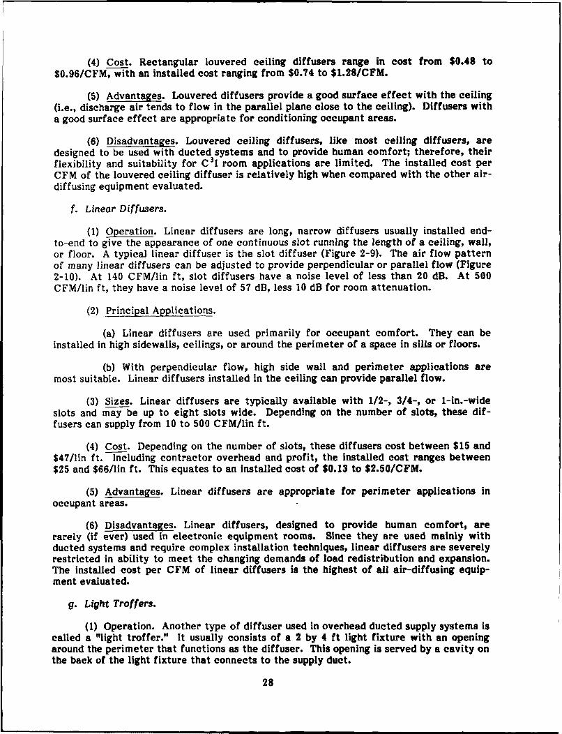
f. Linear Diffusers.
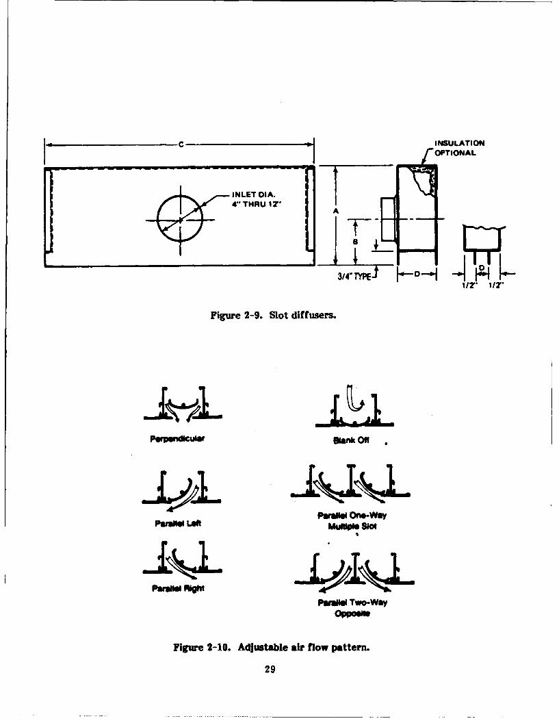
(1) Operation. Linear diffusers are long, narrow diffusers usually installed end-to-end to give the appearance of one continuous slot running the length of a ceiling, wall,or floor. A typical linear diffuser is the slot diffuser (Figure 2-9). The air flow patternof many linear diffusers can be adjusted to provide perpendicular or parallel flow (Figure2-10). At 140 CFM/lin ft, slot diffusers have a noise level of less than 20 dB. At 500CFM/lin ft, they have a noise level of 57 dB, less 10 dB for room attenuation.
(2) Principal Applications.
(a) Linear diffusers are used primarily for occupant comfort. They can beinstalled in high sidewalls, ceilings, or around the perimeter of a space in sills or floors.
(b) With perpendicular flow, high side wall and perimeter applications aremost suitable. Linear diffusers installed in the ceiling can provide parallel flow.
(3) Sizes. Linear diffusers are typically available with 1/2-, 3/4-, or 1-in.-wideslots and may be up to eight slots wide. Depending on the number of slots, these dif-fusers can supply from 10 to 500 CFM/lin ft.
(4) Cost. Depending on the number of slots, these diffusers cost between $15 and$47/lin ft. Including contractor overhead and profit, the installed cost ranges between$25 and $66/lin ft. This equates to an installed cost of $0.13 to $2.50/CFM.
(5) Advantages. Linear diffusers are appropriate for perimeter applications inoccupant areas.
(6) Disadvantages. Linear diffusers, designed to provide human comfort, arerarely (if ever) used in electronic equipment rooms. Since they are used mainly withducted systems and require complex installation techniques, linear diffusers are severelyrestricted in ability to meet the changing demands of load redistribution and expansion.The installed cost per CFM of linear diffusers is the highest of all air-diffusing equip-ment evaluated.
g. Light Troffers.
(1) Operation. Another type of diffuser used in overhead ducted supply systems iscalled a "light troffer." It usually consists of a 2 by 4 ft light fixture with an openingaround the perimeter that functions as the diffuser. This opening is served by a cavity onthe back of the light fixture that connects to the supply duct.
28
C INSULATIONI OPTIONAL
INLET DIA.I4" THRU 12"
3/4"TYPEI 194 ~
1/2" 1/2"'
Figure 2-9. Slot diffusers.
Pp~edlcuier Bn f
Pae One-Way
parafe" MPaal Two-Wy
Figure 2-10. Adjustable air flow pattern.
29
(2) Principal Applications. Light troffers are used mainly for occupant comfort.The maximum flow rate of approximately 150 CFM/troffer is usually inadequate for usein C 3I rooms.
(3) Sizes. Air flow rates for light troffers range from 50 to 150 CFM/troffer.
(4) Cost. Light troffers have an installed cost ranging from $0.20 to $0.60/CFM.These figures reflect the added cost of a light troffer over that of a standard 2 by 4 ftlight fixture.
(5) Advantages. Light troffers are effective for conditioning small individualoffices since they have low CFM rates.
(6) Disadvantages. Light troffers are rarely used in C3I room applications be-cause of their low air flow rates. If used, they will be relatively inflexible in accom-modating the relocation and addition of electronic equipment in the C31 room.
h. Return Air Coverings
(1) Operation.
(a) Return air iniets of ducted return systems are typically covered with thestandard grilles or registers described earlier. Since deflectors have very little effect onreturn air flow patterns, their use is rarely warranted. Simple fixed-bar or stampedgrilles are used most commonly for return air inlets. Registers are sometimes used tobalance return air volume flow rates. In ceiling plenum return systems, the perforatedface of the ceiling diffuser is commonly used for the return air inlet covering.
(b) Return grilles and registers generally have noise levels of about 15 dB at aduct/plenum velocity of 400 FPM. At 1000 FPM, the noise level can reach 48 dB. Thenoise level of the perforated ceiling diffuser, used as a return air inlet cover, is typicallyless than 20 dB at plenum velocities of up to 1000 FPM.
(2) Principal Applications.
(a) Grilles and registers can be used as return air inlet covers for both ductedand plenum return systems. The same is true for perforated ceiling diffusers.
(b) In addition to standard grilles, transfer grilles are used to deliver return airfrom the conditioned space to a remote space where the return inlet is located. Transfergrilles are installed in walls or doors. A common transfer grille is the V-bar type con-sisting of a set of V-shaped louvers stacked on top of each other. This configurationeliminates direct line-of-sight vision through the transfer grille.
(3) Sizes. Return air grilles are commonly available in sizes ranging from 6 by 6in. to 48 by 48 in. Perforated ceiling return inlets typically measure 24 by 24 in., ena-bling easy substitution for standard suspended ceiling panels. Transfer grilles range insize from 8 by 4 in. to 30 by 30 in.
(4) Cost. For a 6 by 6 In. return air grille rated at 125 CFM, the material cost isapproximately $0.05/CFM and the installed cost is about $0.14/CFM. A 48 by 48 in.grille at 8000 CFM costs $0.02/CFM, with an Installed cost of $0.03/CFM. Perforatedceiling diffusers without deflectors used as return inlet covers range in cost from $0.007to $0.03/CFM, with the installed cost ranging from $0.008 to $0.04/CFM.
30

(5) Advantages/Disadvantages. Grilles, registers, and perforated ceiling returninlet covers have different negative static pressure properties. The cost per CFM of aparticular type of return air inlet cover must be balanced against the effect of the staticpressure curve on fan power requirements when evaluating the life-cycle cost of anoverall cooling system.
2-3. Other Considerations
a. Static Pressure Impact. Another consideration is that the static pressure pro-perties of air-diffusing equipment will have an impact on fan energy requirements.Figure 2-11 is a plot of static pressure versus CFM for several different types and sizesof air-diffusing equipment. The plot indicates that, for a flow rate of 800 CFM, theperforated ceiling diffuser has the highest static pressure. Note that the louvered ceilingand linear diffusers have the lowest static pressures for any given CFM. While per-forated floor panels and perforated ceiling diffusers have a low first cost, they also havehigh fan energy requirements.
b. EMP Protection. The penetrations to EMP shielding caused by air distributionsystems are among the largest in the C 31 facility. The protection parameters for airdistribution penetrations are the same as those for piping penetrations (see Chapter 3,Chilled Liquid Distribution Systems). In both cases, the waveguide-beyond-cutoff tech-nique is used. The waveguide must be made of a conductive material and must be con-tinuously welded or soldered to the primary EMP shield so that current flowing on thewaveguide can be discharged to the primary EMP shield. The maximum inside diameterof the penetration must be 4 in. or less to achieve a cutoff frequency of 1.47 GHz for arectangular penetration and 1.73 GHz for a cylindrical penetration. The unbroken lengthof conducting material adjacent to the penetration must be a minimum of five times thediameter of the conducting material (i.e., pipe, duct) to attenuate by at least 100 dB atthe required frequencies. Since, in general, ventilation duct dimensions cannot reason-ably be limited within the 4-in. restriction, the duct itself cannot be used as the wave-guide.
(1) EMP protection for air distribution penetrations uses a "honeycomb" wave-guide air vent panel (Figure 2-12). As the term "honeycomb" implies, the cross sectionalarea of the panel is divided into a number of cells (Figure 2-13), each of which complieswith the 4-in. maximum diameter and five-diameter length requirements. The gridstructure must be metallic and all joints must be continuously bonded.
(2) Honeycomb panels are commercially available in dimensions up to 18 by 18in. Larger panels can be made by soldering the seams of multiple panels. The honey-comb material is normally cadmium-coated steel or tinned brass. This material issoldered into a steel frame, which Is subsequently welded into the penetration plate(Figure 2-14) or attached with RFI gasketed and bolted seals.
(3) The material retail cost of a honeycomb air vent panel is about $50/sq ft. Thecost to weld the frame to the penetration plate results In an Installed cost of $70 to$80/sq ft of penetration area. If multiple panels are required to protect a large pene-tration, the cost of soldering together the seams of the panels will Increase the costssignificantly.
31

Selected Air-Diffusing Equipment0.3 - I
0.28 -1 Perforated Floor / 16"06" GrillPanel I0.26
0.24 - // /
0.22 //I
0.2 - 24"x24" /Perforated
) 0.18 - Ceiling / /0.16Diffuser / / 6' long, 6" wideC 0. 16 -t/"
I // ."
0.12 - / /./ 24"24
d- 0.1 ' Louvered_,- Di , j ffuser I ..o 008 -- w/14" neck
0.06 /
I /0.04 -
0.02 .-
0-0 0.4 0.8 1.2 1.6 2 2.4 2.8
(Thousands)
Cubic Feet per Minute
Figure 2-11. Static pressure vs. volume flow rate.
Fiwe 2-12. Honeycomb wavquide air vent panel. (Source: USAF Handbook forthe Design and Construction of HEMP/TEMPEST Shielded Facilities[1986].)
32
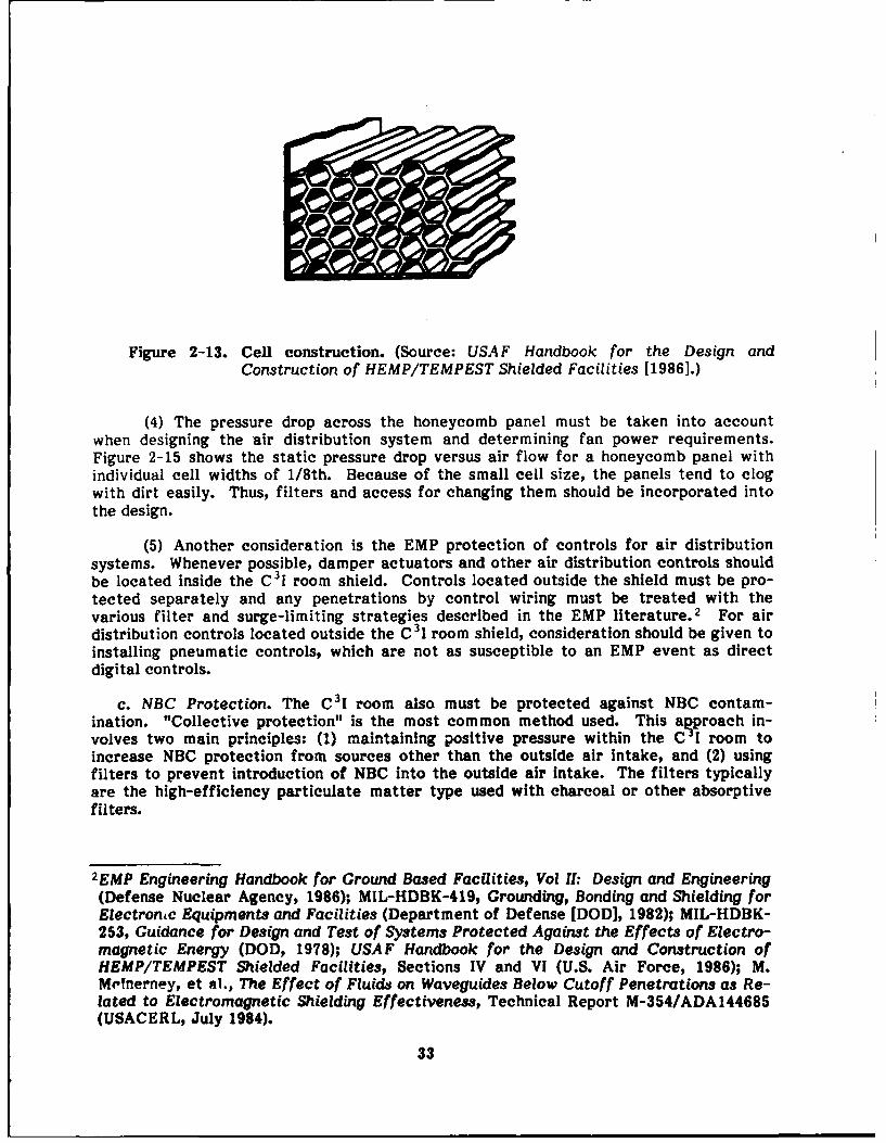
Figure 2-13. Cell construction. (Source: USAF Handbook for the Design andConstruction of HEMP/TEMPEST Shielded Facilities [1986].)
(4) The pressure drop across the honeycomb panel must be taken into accountwhen designing the air distribution system and determining fan power requirements.Figure 2-15 shows the static pressure drop versus air flow for a honeycomb panel withindividual cell widths of 1/8th. Because of the small cell size, the panels tend to clogwith dirt easily. Thus, filters and access for changing them should be incorporated intothe design.
(5) Another consideration is the EMP protection of controls for air distributionsystems. Whenever possible, damper actuators and other air distribution controls shouldbe located inside the C 3 I room shield. Controls located outside the shield must be pro-tected separately and any penetrations by control wiring must be treated with thevarious filter and surge-limiting strategies described in the EMP literature. 2 For airdistribution controls located outside the C31 room shield, consideration should be given toinstalling pneumatic controls, which are not as susceptible to an EMP event as directdigital controls.
c. NBC Protection. The C3I room also must be protected against NBC contam-ination. "Collective protection" is the most common method used. This agproach in-volves two main principles: (1) maintaining positive pressure within the C I room toincrease NBC protection from sources other than the outside air intake, and (2) usingfilters to prevent introduction of NBC into the outside air intake. The filters typicallyare the high-efficiency particulate matter type used with charcoal or other absorptivefilters.
2EMP Engineering Handbook for Ground Based Facilities, Vol II: Design and Engineering(Defense Nuclear Agency, 1986); MIL-HDBK-4199 Grounding, Bonding and Shielding forElectronc Equipments and Facilities (Department of Defense [DOD], 1982); MIL-HDBK-253, Guidance for Design and Test of Systems Protected Against the Effects of Electro-magnetic Energy (DOD, 1978); USAF Handbook for the Design and Construction ofHEMP/TEMPEST Shielded Facilities, Sections IV and VI (U.S. Air Force, 1986); M.M'Tnerney, et M., The Effect of Fluids on Waveguides Below Cutoff Penetrations as Re-lated to Electromagnetic Shielding Effectiveness, Technical Report M-354/ADA144685(USACERL, July 1984).
33

W 1 4 W2 4 10.2 CM (4) ,,PRIMARY SHIELD
SAPENETRATION PLATE
CIRCUMFERENTIALWELD
Figure 2-14. Honeycomb waveguide panel attached to primary shield. (Souree:USAF Handbook for the Design and Construction of HEMP/TEMPESTShielded Facilities [1986J.)
HONEYCOMB EMP AIR VENT PANELS(Honeycont el wit u 1/8 hIsh)
I. , _____ _,'f/ ,
0 6 10 15, 50 25 20AF LOW (CPMSO. 14.)
Figure 2-15. Ar flow eharacterpsties of a honeycomb panel.
34
(1) NBC filters produce a large drop in pressure in the air distribution system.Therefore, fans and fan motors must be sized approximately 20 to 30 percent larger toovercome this pressure drop. Due to the increased fan energy costs, the system isusually designed to bypass NBC filters under normal operation. NBC detection sensorsand alarms will signal the bypass damper to direct outside air through the filters in theevent of NBC contamination. Provisions must be made in the design to enable personnelto change the NBC filters without exposure to NBC contamination.
(2) NBC filters are quite expensive. Collective protection can add 10 to 15percent to the construction cost of a facility.
Section HI: SUMMARY EVALUATION
2-4. How To Use the Evaluation Table
a. Table 2-1 ranks each air distribution system component on the criteria presentedin Section 1. These rankings are qualitative, with a black circle representing a highranking, a gray circle denoting a medium ranking, and a white circle indicating a lowrating. It should be noted that a low rating simply means that other components aremore suitable for a specific criterion, and not necessarily that the component is a poorchoice in general.
b. For a particular criterion, only the rankings of components in the same categoryshould be compared. For example, when the primary consideration is life-cycle cost, theceiling plenum supply, free return, and perforated floor panels all have a high rating.However, a free return and perforated floor panels cannot be used with a ceiling plenumsupply system. Instead, the ranking of the ceiling plenum supply system should be com-pared only with that of the underfloor plenum and overhead ducted supply systems.Similarly, a certain return system should be compared with other return systems and aparticular diffuser should be compared with other air-diffusing equipment.
c. When ranking each component, certain assumptions were made regarding thesystem configuration. These assumptions were based on the most typical system con-figuration in which each component is used. It was assumed that the underfloor plenumsupply system is served by air handlers located within the C3I room. The ceiling plenumand overhead ducted supply systems were assumed to be served by a remotely located airhandler. Similarly, it was assumed that the ceiling plenum and ducted return systemsserve a remote air handler and that the free return system serves air handlers inside theelectronic equipment room.
(1) It was also assumed that VAV and CV mixing boxes are used with overheadducted supply systems. Furthermore, it was assumed that the boxes are used with eitherthe ceiling plenum or ducted return system, but not with the free return system.
(2) In most cases, air-diffusing equipment was assumed to be used with the supplysystem for which it is most suitable. For example, it was assumed that perforated floorpanels are used with the underfloor plenum supply system and that louvered and lineardiffusers are used with the overhead ducted supply system. While it was assumed thatperforated ceiling diffusers are used with the ceiling plenum supply system, they can alsobe installed with ducted systems. Grilles and registers can also he used with plenum andducted systems.
35
Table 2-1. Summary Evaluation--Air Distribution Systems
AIR DISTRIBUTION EQUIPMENT........
2) Cei"ing Plenum Supply 0 (D 0 0 N/A 0 0 0 * A high ranking-Cin e-p- - -- for cost-related
3) Overhead Ducted Supply 0 0 G 0 N/A ( 0 0 criteria indicatesA) with VAV Boxes 0 0 0 0 G N/A 0 0 a low relative, cost. A low
8) with CV Boxes (D 0 * 0 N/A 0 C 0 Q ranking indicatesRet .- ~- - - high relative
___________________mom_ cost.4) Free Return * 0 0 0 0 N/A 0 * *5) Ceiling Plenum O 0 0 0 (Q N/A 0 016) Ducted Return 00 (D a N/A C) 01
_AIR-DIFFUSING EQUIPMENT . i i) Perforated Floor Panels 9 9 . N/A 9 N/A N/A •
2) Perforated Ceiling Diffusers 0 _N/A 0 N/A N/ A.3) Grilles and Registers 0 0 0 N/A ( N/A 0 N/A C04) Louvered Ceiling Diffusers 0 0 :N/A' N/A * N/A 0
5) Linear Diffusers 0 0 0 N/A 0 N/A N/A 06) Light Troffers Q _Q N/A 0 NI .A N/A O
• = High ( = Medium 0 = Low
2-5. Evaluation Results
a. Load Redistribution. When load redistribution is the primary consideration, theunderfloor plenum supply system has the best ranking. As mentioned, it Is assumed thatair handlers (either chilled water or DX) located within the C3 I room serve the under-floor glenum. Though not listed as one of the criteria, the availability of space withinthe C f room is often a critical factor. In this case, the space within the C3 1 roomoccupied by the air handlers may preclude the use of the underfloor plenum supply sys-tem even though load redistribution and expansion are also important considerations.The same reasoning applies to the free return system, since it can only be used with anunderfloor supply plenum based on the assumed configurations.
36
b. Load Expansion. When load expansion is the primary consideration, the underfloorplenum supply system has the best ranking. Again, It is assumed that air handlers locatedwithin the C I room serve the underfloor plenum. Load expansion is accommodated byinstalling additional air handlers to satisfy the extra cooling load. This modification canoften be done without shutting down the existing air handlers. With a remotely locatedair handler, the supply CFM must be increased to satisfy the additional cooling load. Inaddition, it may be necessary to increase the size cf the cooling coil to increase thecooling capacity. These types of modifications require that the air handler be shut down.
c. Precise Control of Humidity.
(1) Chiller and air-handler controls are primarily responsible for regulating thehumidity level of the C31 room within required limits. The rankings for the precisecontrol of humidity criterion are based on the ability of the air distribution systemcomponents to quickly equalize the differences in humidity between room air and dis-charge air within the C 31 room.
(2) Because of their high entrainment ratio, perforated floor panels and per-forated ceiling diffusers received high ratings. Since this equipment is typically usedwith certain supply systems, the underfloor plenum and ceiling plenum supply systemswere also ranked highly.
(3) The remaining air-diffusing equipment, and the supply systems used with it,had almost the same ability to quickly equalize the differences in humidity between roomair and discharge air within the C I room. Therefore, they all received a mediumrating. However, the VAV box system received a low rating since, during periods of lowcooling load, air flow is reduced significantly.
d. Filtering of Particulate Matter.
(1) The ability to filter particulate matter from ventilation makeup air is fullyevaluated in Chapter 4. In terms of air distribution systems, rankings for the filteringcriterion are based on the system's ability to minimiz- the 1itred,,ct-Vn of dust and debrisinto the recirculated air stream.
(2) Since the overhead ducted supply system is more likely to stay clean than aceiling plenum supply system, the overhead ducted supply system, together with the VAVand CV box variations, received high ratings. The ceiling plenum supply system wasgiven a medium ranking since it is more likely to stay clean than an underfloor plenumsupply system. By this reasoning, the underfloor plenum supply system was given a lowrating. It should be stressed that none of the three supply systems compromise thecooling system's ability to filter particulate matter.
(3) Similarly, although none of the return systems compromise filtering ability,the ducted return system was given a high rating, the ceiling plenum return system wasrated medium, and the free return system received a low rating.
(4) Filtering, as evaluated for air distribution systems, was considered to be afunction of the supply and return systems and not applicable to air-diffusing equipment.Table 2-1 indicates this approach by noting "N/A" for the air-diffusing equipment on thiscriterion.
e. Static Electricity Control. For cooling systems, a major factor in controllingstatic electricity is the regulation of humidity within the C I room. As mentioned,
37

chiller and air-handler controls are primarily responsible for humidity control. For airdistribution systems, the fact that raised floor and perforated floor panels are availablewith antistatic and conductive coatings gave the underfloor plenum supply and perforatedfloor panels high ratings. All other system components were considered equal in terms ofstatic electricity control and, therefore, were given a medium ranking.
f. Backup Cooling Capacity. The capacity of a cooling system to provide 15 min ofbackup cooling in the event of a power failure depends on the configuration of the chilledwater distribution system. For this reason, ranking air distribution system componentsfor the backup cooling criterion is not applicable and is so indicated by "N/A" inTable 2-1.
g. Reliability.
(1) Reliability is fairly equal among the different system components. If com-parisons must be made, components with moving parts are more susceptible to mal-function than those with no moving parts. Malfunction is defined here to mean eitherbreakage, sticking, or improper adjustment by C 31 room occupants. Since the VAV andCV mixing box variations of the overhead ducted supply system have moving parts, theyreceived a medium rating. The remaining supply and return systems generally have nomoving parts; all received a high ranking.
(2) While all of the air-diffusing equipment evaluated is reliable, rankings werebased on the relative susceptibility for malfunction as just discussed. For the evaluation,it was assumed that none of the air-diffusing equipment is fitted with opposed-bladedampers for air volume control. One exception is the register, which by definition in-cludes a volume control device. Perforated floor panels, louvered ceiling diffusers,perforated ceiling diffusers, and linear diffusers all received a high reliability ratingsince they typically have no moving parts. Grilles and registers received a mediumranking since they often have movable deflectors that can be adjusted by occupants inthe space.
h. Least Cost for EMP Shielding.
(1) Component ranking for the criterion "least cost for EMP shielding" was basedon the relative size of the shielding penetrations associated with the typical con-figuration for the supply and return components. It was assumed that the C 3I room itselfis EMP-shielded. For the underfloor plenum supply system, air handlers serving theplenum are typically located inside the C 3I room and a free return system is used. Thisconfiguration requires relatively small fresh air ducts compared with the ducts sized fortotal supply air associated with remotely located air handlers.
(2) With the air handlers located within the space, the only other penetrations arethose made by the air-handler piping (i.e., chilled water, condenser, condensate, andhumidifier water). Since the relative size of all penetrations to the EMP shield aresmaller for systems with air handlers located within the C31 room than those with re-motely located air handlers, the underfloor plenum supply and free return systemsreceived high ratings.
(3) Because the typical configurations of the remaining supply and return systemsinvolve penetrating the C3I room EMP shield with ductwork sized for total supply air,they received a medium rating. It should be noted that the difference in cost for EMPshielding among the supply and return systems is marginal and that the rankings for thiscriterion merely reflect the considerations just described.
38
(4) Ranking air-diffusing equipment in terms of least cost for EMP shielding is not
applicable since these components are always located inside the shield.
i. Lowest Life-Cycle Cost.
(1) A high ranking for the life-cycle cost criterion indicates a relatively low life-cycle cost. Conversely, a low rating denotes a relatively high life-cycle cost. Since nodirect costs and negligible maintenance costs are generally associated with air distri-bution systems, the life-cycle cost criterion is basically an issue of first cost. Of thefive supply systems evaluated, the ceiling plenum supply system has the lowest life-cyclecost per unit of C 3 1 room floor area and was given a high rating. The underfloor plenumsupply system was next lowest in cost and was, therefore, ranked as medium. The over-head ducted supply system, together with the VAV and CV mixing box variations, are themost expensive and received a low ranking. It should be noted that the difference in costbetween the ceiling and underfloor plenum supply systems is small compared with thesubstantial cost premium of the overhead ducted supply system and its variations.
(2) The free return system has the lowest life-cycle cost and, therefore, receiveda high ranking. The ceiling plenum return system received a medium ranking and theducted return system was ranked low. It is imoortant to note that use of the free returnor ceiiing plenum return system with air handlers located inside the C3 1 room may re-quire that a separate system be installed to introduce outside air. The costs of eachsystem could thus become higher than that of a ducted return system, which is typicallyused with a central station air handler that mixes outside air with return air.
(3) The average installed cost per CFM was determined for each diffuser, grille,
and register type. These average costs were then divided into three groups correspondingto the three degrees of rank. The perforated ceiling diffuser and perforated floor panelhave the lowest average cost and, therefore, were ranked high. Grilles, registers andlight troffers are the next most expensive and received a medium ranking. The averagecost of the louvered ceiling diffuser and the linear diffuser are both high, so they bothwere ranked low.
(4) As mentioned, no direct costs and negligible maintenance costs are associatedwith air distribution systems, so the life-cycle cost criterion is basically that of firstcost. However, there are some indirect operating costs associated with some systemcomponents. For instance, the cost of the C 3 1 room floor space occupied by air handlersir the underfloor plenum supply system was not considered during the ranking process,but should be taken into account when designing the overall cooling system.
39

3 CHILLED LIQUID DISTRIBUTION SYSTEMS
Section I: GENERAL
This chapter evaluates design approaches for chilled liquid distribution systems servingelectronic equipment rooms. The following criteria are used to evaluate each distri-bution system:
1. Flexibility in meeting load redistribution.
2. Flexibility in meeting load expansion.
3. Capacity to provide 15 min of backup cooling.
4. Reliability.
5. Least cost for EMP shielding.
6. Lowest life-cycle cost.
Most criteria do not apply to distribution system components. The evaluation was donefor completeness only.
3-1. System Types
a. Although there are many distribution arrangements for supplying chilled water toC3I rooms, three "generic" ones that represent the major variations are described andevaluated in this chapter. These are:
(1) A central chiller serving the C 3I room, C 3I building, and other buildings.
(2) A chiller serving the C3I room and C 3I building.
(3) One chiller serving the C 3I room and another chiller serving the C3I building.
b. There are several ways to provide chilled water to the air handlers and electronicequipment within the C 3I room. These approaches are described and evaluated alongwith a piping configuration for meeting the C3I requirement of 15 min backup cooling.
c. In addition to piping configurations outside and inside the C 31 room, the majorpiping system components are described and evaluated. These are piping, valves, andpumps. The discussion of the these components Includes information on sizes and costs.However, the size and cost of the configurations depend on the specific application and,therefore, are not discussed in detail.
d. After each piping configuration or component is fully described, the configurationsare evaluated according to the criteria listed in Section I above. The evaluation tablesummarizes the results of the qualitative ranking procedure (see Section III of thischapter).
40
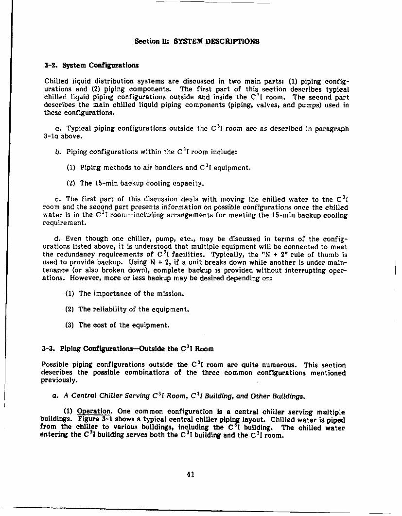
Section H: SYSTEM DESCRIPTIONS
3-2. System Configurations
Chilled liquid distribution systems are discussed in two main parts: (1) piping config-urations and (2) piping components. The first part of this section describes typicalchilled liquid piping configurations outside and inside the C 3I room. The second partdescribes the main chilled liquid piping components (piping, valves, and pumps) used inthese configurations.
a. Typical piping configurations outside the C 3j room are as described in paragraph
3-1a above.
b. Piping configurations within the C3 1 room include:
(1) Piping methods to air handlers and C 31 equipment.
(2) The 15-min backup cooling capacity.
c. The first part of this discussion deals with moving the chilled water to the C 31room and the second part presents information on possible configurations once the chilledwater is in the C 31 room--including arrangements for meeting the 15-min backup coolingrequirement.
d. Even though one chiller, pump, etc., may be discussed in terms of the config-urations listed above, it is understood that multiple equipment will be connected to meetthe redundancy requirements of C31 facilities. Typically, the "N + 2" rule of thumb isused to provide backup. Using N + 2, if a unit breaks down while another is under main-tenance (or also broken down), complete backup is provided without interrupting oper-ations. However, more or less backup may be desired depending on:
(1) The importance of the mission.
(2) The reliability of the equipment.
(3) The cost of the equipment.
3-3. Piping Configurations--Outside the C31 Room
Possible piping configurations outside the C31 room are quite numerous. This sectiondescribes the possible combinations of the three common configurations mentionedpreviously.
a. A Central Chiller Serving C 31 Room, C 31 Building, and Other Buildings.
(1) Operation. One common configuration is a central chiller serving multiplebuildings. Figure 3-1 shows a typical central chiller pipinF layout. Chilled water is pipedfrom the chiller to various buildings, including the C I building. The chilled waterentering the C3 I building serves both the C3 1 building and the C 31 room.
41
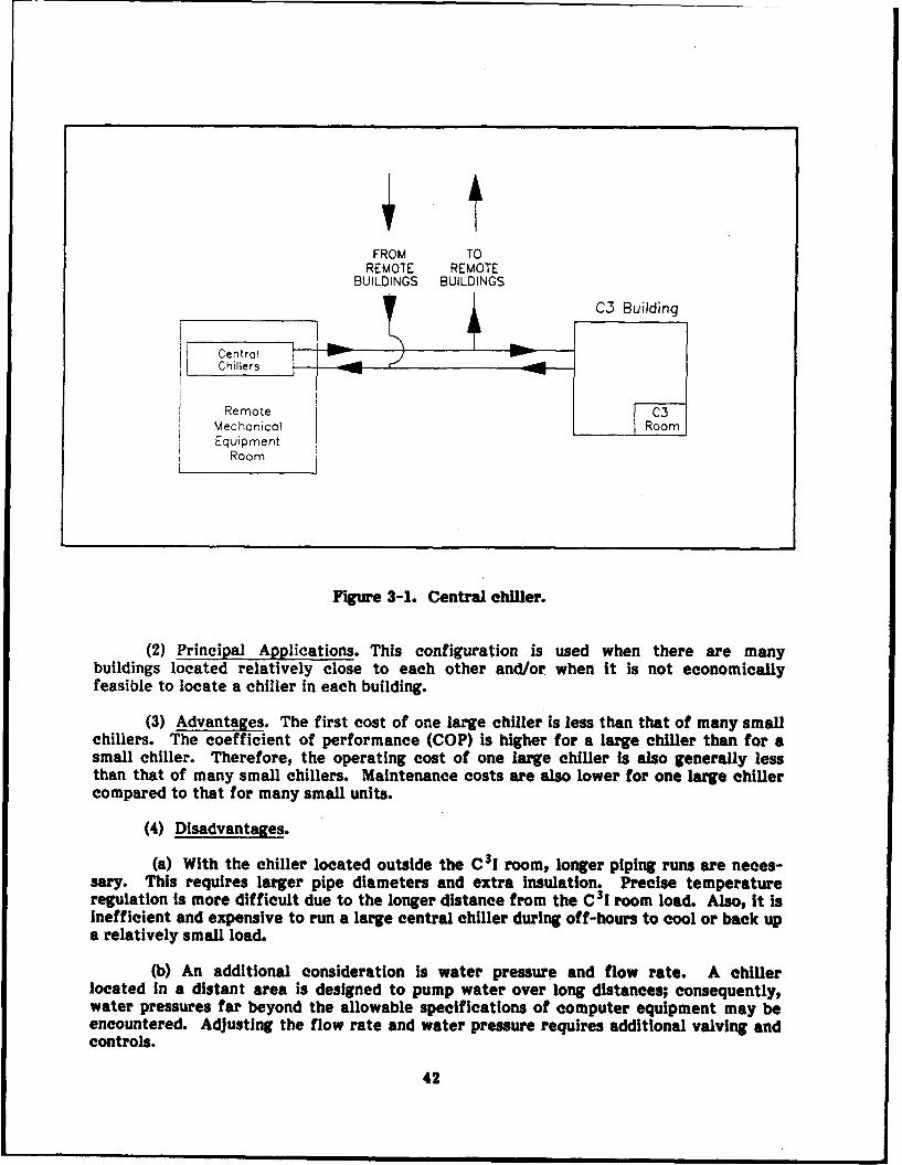
FROM TOREMOTE REMOTE
BUILDINGS BUILDINGS
C3 Building
Cer'trolChillers
Remote C3Mechanical RoomEquipment
Room
Figure 3-1. Central chiller.
(2) Principal Applications. This configuration is used when there are manybuildings located relatively close to each other and/or when it is not economicallyfeasible to locate a chiller in each building.
(3) Advantages. The first cost of one large chiller is less than that of many smallchillers. The coefficient of performance (COP) is higher for a large chiller than for asmall chiller. Therefore, the operating cost of one large chiller is also generally lessthan that of many small chillers. Maintenance costs are also lower for one large chillercompared to that for many small units.
(4) Disadvantages.
(a) With the chiller located outside the C3 I room, longer piping runs are neces-sary. This requires larger pipe diameters and extra insulation. Precise temperatureregulation is more difficult due to the longer distance from the C 31 room load. Also, it isinefficient and expensive to run a large central chiller during off-hours to cool or back upa relatively small load.
(b) An additional consideration is water pressure and flow rate. A chillerlocated in a distant area is designed to pump water over long distances; consequently,water pressures far beyond the allowable specifications of computer equipment may beencountered. Adjusting the flow rate and water pressure requires additional valving andcontrols.
42

(c) EMP protection is also a concern. If many of the buildings served by thiscentral chiller are EMP-protected, more penetration points are required. Since thechiller serves an EMP-protected building or room, it also must be protected. Incontrast, if the chiller is located within a shielded building, it does not require additionalprotection.
(d) Finally, if the chiller is located far away from the critical facility, thechilled water piping will cover long distances. If the piping has to travel through anunsecured/unprotected area, it will be exposed to possible sabotage or attack fromsomeone trying to deter operations. Also, longer pipe runs increase the possibility ofundetected leaks since the entire length of pipe is more difficult to inspect.
b. Chiller Serving C 3I Room and C 3I Building.
(1) Operation. Figure 3-2 is a schematic of a C3 I building chiller configuration.This chiller serves the building air-handling units and/or the chilled water loop. Inaddition, the C 31 room is served by the building chiller.
(2) Principal Applications. This configuration is commonly used when there is adedicated building chiller and the C 31 room loads are relatively small and do not requirea dedicated chiller.
(3) Advantages. If the building containing the chiller is EMP-shielded, the chillerdoes not need to be shielded. Also, the chiller will be more responsive to changing loadsthan the first configuration since it will be closer in size and proximity to the C 3I roomloads.
C3 BUILDING
BUILDINGCHiLLERS c7
___,-______- ROOM
, __ ___
From BuildingAHU's and/or
o uj, Chilled Water
AHU's and/ Loopor ChilledWater Loop-7V
Figure 3-2. C31 building chiller.
43
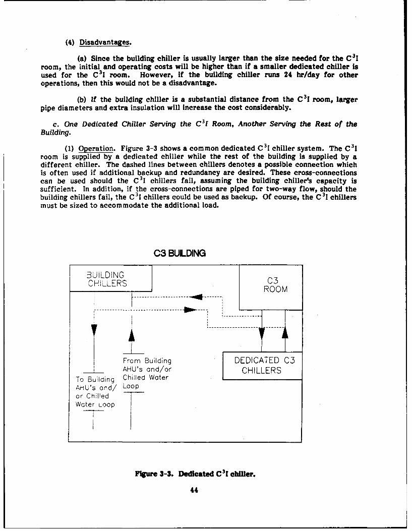
(4) Disadvantages.
(a) Since the building chiller is usually larger than the size needed for the C 3Iroom, the initial and operating costs will be higher than if a smaller dedicated chiller isused for the C31 room. However, if the building chiller runs 24 hr/day for otheroperations, then this would not be a disadvantage.
(b) If the building chiller is a substantial distance from the C31 room, largerpipe diameters and extra insulation will increase the cost considerably.
c. One Dedicated Chiller Serving the C 31 Room, Another Serving the Rest of theBuilding.
(1) Operation. Figure 3-3 shows a common dedicated C 31 chiller system. The C31room is supplied by a dedicated chiller while the rest of the building is supplied by adifferent chiller. The dashed lines between chillers denotes a possible connection whichis often used if additional backup and redundancy are desired. These cross-connectionscan be used should the C 31 chillers fail, assuming the building chiller's capacity issufficient. In addition, if the cross-connections are piped for two-way flow, should thebuilding chillers fail, the C3i chillers could be used as backup. Of course, the C 3I chillersmust be sized to accommodate the additional load.
C3 BULDING
BUILDING 3CHILLERS C3
___ , IROOM-- ----------a -- --
-------------- ------------------- ------ I
From Building DEDICATED C3
_ AHU's and/or CHILLERSTo Building Chilled WaterAHU's and/ Loopor ChilledWater Loop
Figure 3-3. Dedicated C 31 chiller.
44
(2) Principal Applications. Dedicated C 3I room chillers are used when continuousoperation of the C'I room is necessary and it is not economically feasible to run thebuilding chillers or central chillers for 24 hr/day. If the C 1 room load is smaller than 40percent of the chiller's rated capacity, then a dedicated chiller is usually used. Manycentrifugal chillers cannot operate below 40 percent rated capacity due to surging. Thiscondition is discussed further in Chapter 5.
(3) Advantages.
(a) The chiller is responsive to changing loads and expansion. Since many C 3 Irooms require 24-hr operation, it is more cost-effective to run the size of chiller neededrather than run a large chiller for a comparatively small load.
(b) If the cross-connection between the dedicated chiller system and the buildingchiller is used, this arrangement would provide an additional level of redundancy. Thatis, not only would there be redundancy with the dedicated C 3I room chillers, but if theywere to fail, the building chillers could be used.
(4) Disadvantages. With more chillers and piping configurations, the costs formaintenance, monitoring, and control increase.
3-4. Piping Configurations-Inside the C3I Room
This paragraph discusses various ways of piping chilled water inside the C 3I room. Inchilled-water cooling systems, chilled water is commonly piped from a chiller to a re-mote air-handling unit and then directly to items in the C3 I room. If chilled water ispiped to a remote air-handling unit, conditioned air is then supplied to the C 3I room usingone or a combination of the air-supply systems discussed Chapter 2. If chilled water ispiped to the C 3I room, one or a combination of the following may be served: (1) roomair-handling units, (2) fan coil units, and (3) water-cooled electronic equipment.
a. Interior C 3I Room Piping.
(1) Operation. Figure 3-4 shows a common piping configuration used when chilledwater is piped to the C31 room.
(a) The branches could serve air handlers, fan coils, or water-cooled electronicequipment as noted above. The sectional valves and multiple valved branch connectionspermit modifications such as adding an air handler without requiring complete shut-down. Valve mains can also be added for cross-connection or expansion. Adding extravalves and branch connections will increase the life-cycle cost, but load redistributionand expansion capabilities are also Increased.
(b) The piping could be above the C3I room ceiling, but it is more commonly rununder the floor when the C 3I room has a raised floor system.
(2) Principal Applications. This piping method is used when:
(a) There is not an abundance of computer wiring or other obstructions under theC 31 flooring.
(b) The depth of the raised flooring allows for underfloor piping without ob-structing the computer room air-handler unit's air flow or interfering with computerwiring.
45
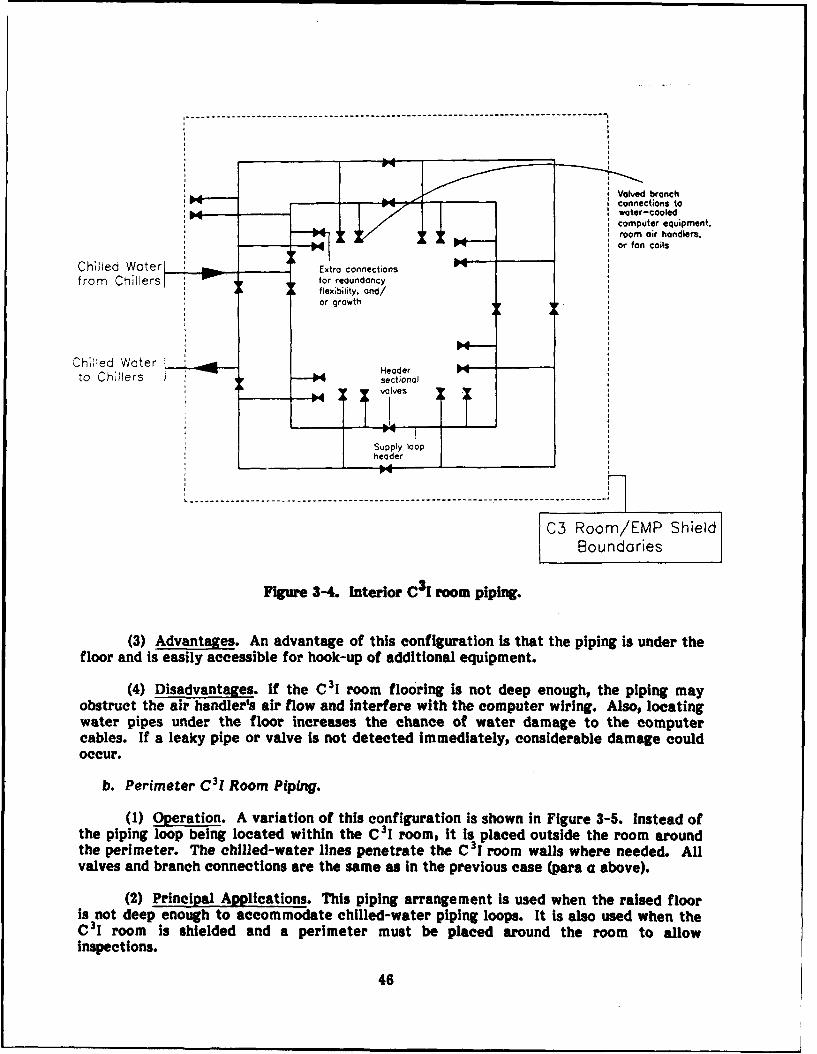
Valved branch
connections to
:04 water-cooledcomputer equipment.room air handlers.
Xor fan coils
Chilled Water Extra connectionsfrom Chillers Ifor redundancy
A A flexibility, and/or growth
Chilled Water Ito Chillers sectionalA= valIves
vOvISupply loopheader
C3 Room/EMP ShieldBoundaries
Figure 3-4. Interior C3 1 room piping.
(3) Advantages. An advantage of this configuration is that the piping is under thefloor and is easily accessible for hook-up of additional equipment.
(4) Disadvantages. If the C31 room flooring is not deep enough, the piping mayobstruct the air handler's air flow and Interfere with the computer wiring. Also, locatingwater pipes under the floor increases the chance of water damage to the computercables. If a leaky pipe or valve Is not detected immediately, considerable damage couldoccur.
b. Perimeter C31 Room Piping.
(1) Operation. A variation of this configuration is shown in Figure 3-5. Instead ofthe piping loop being located within the C31 room, It Is placed outside the room aroundthe perimeter. The chilled-water lines penetrate the C3i room walls where needed. Allvalves and branch connections are the same as in the previous case (para a above).
(2) Principal Applications. This piping arrangement Is used when the raised flooris not deep enough to accommodate chilled-water piping loops. It is also used when theC3 1 room is shielded and a perimeter must be placed around the room to allowinspections.
46
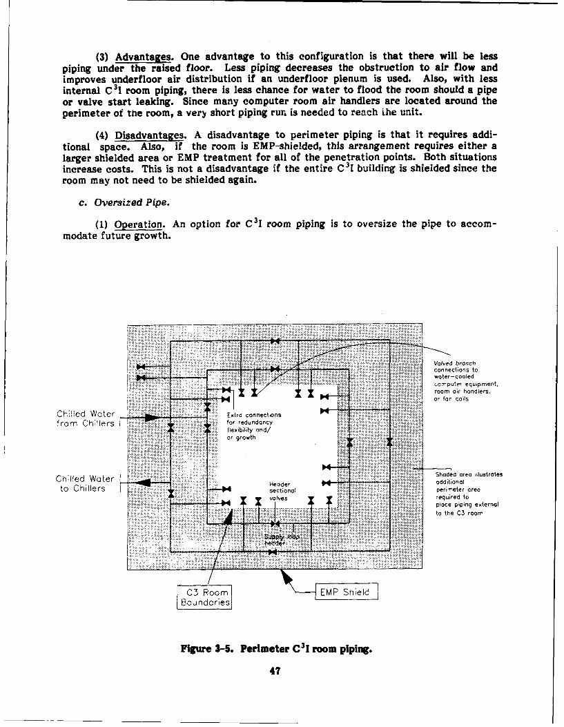
(3) Advantages. One advantage to this configuration is that there will be lesspiping under the raised floor. Less piping decreases the obstruction to air flow andimproves underfloor air distribution if an underfloor plenum is used. Also, with lessinternal C 31 room piping, there is less chance for water to flood the room should a pipeor valve start leaking. Since many computer room air handlers are located around theperimeter of the room, a very short piping run is needed to reach ihe unit.
(4) Disadvantages. A disadvantage to perimeter piping is that it requires addi-tional space. Also, if the room is EMP-shielded, this arrangement requires either alarger shielded area or EMP treatment for all of the penetration points. Both situationsincrease costs. This is not a disadvantage if the entire C3 I building is shielded since theroom may not need to be shielded again.
c. Oversized Pipe.
(1) Operation. An option for C31 room piping is to oversize the pipe to accom-modate future growth.
Valved branchconnections to
. .. . water-cooledcomputer equipment.room air handlers.i~iii iii~iiii,;i ior fa o il
Ch Iled Water u... Extra connectionsfro Chiler for redundancyL~flexibility and/
... or rowth... . ..... .
Chlled Water :Shaded area illustratesChiled Water I :::::Hae additonal
to Chillers sectional perimeter area; I F~ii v e : :: required toplace piping external
SC3 Room "---EMP Shnield 1
Boundories
Figure 3-5. Perimeter C3 I room piping.
47
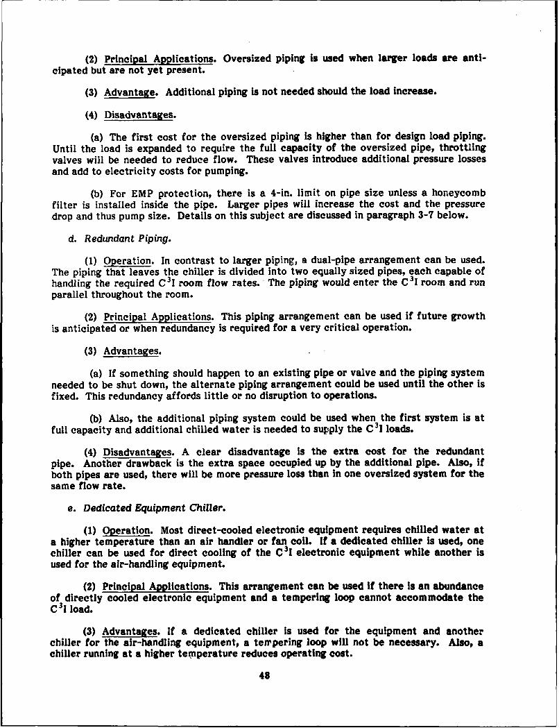
(2) Principal Applications. Oversized piping is used when larger loads are anti-
cipated but are not yet present.
(3) Advantage. Additional piping is not needed should the load increase.
(4) Disadvantages.
(a) The first cost for the oversized piping is higher than for design load piping.Until the load is expanded to require the full capacity of the oversized pipe, throttlingvalves will be needed to reduce flow. These valves introduce additional pressure lossesand add to electricity costs for pumping.
(b) For EMP protection, there is a 4-in. limit on pipe size unless a honeycombfilter is installed inside the pipe. Larger pipes will increase the cost and the pressuredrop and thus pump size. Details on this subject are discussed in paragraph 3-7 below.
d. Redundant Piping.
(1) Operation. In contrast to larger piping, a dual-pipe arrangement can be used.The piping that leaves the chiller is divided into two equally sized pipes, each capable ofhandling the required C3 1 room flow rates. The piping would enter the C3 I room and runparallel throughout the room.
(2) Principal Applications. This piping arrangement can be used if future growthis anticipated or when redundancy is required for a very critical operation.
(3) Advantages.
(a) If something should happen to an existing pipe or valve and the piping systemneeded to be shut down, the alternate piping arrangement could be used until the other isfixed. This redundancy affords little or no disruption to operations.
(b) Also, the additional piping system could be used when the first system is atfull capacity and additional chilled water is needed to supply the C31 loads.
(4) Disadvantages. A clear disadvantage is the extra cost for the redundantpipe. Another drawback is the extra space occupied up by the additional pipe. Also, ifboth pipes are used, there will be more pressure loss than In one oversized system for thesame flow rate.
e. Dedicated Equipment Chiller.
(1) Operation. Most direct-cooled electronic equipment requires chilled water ata higher temperature than an air handler or fan coil. If a dedicated chiller is used, onechiller can be used for direct cooling of the C3I electronic equipment while another isused for the air-handling equipment.
(2) Principal Applications. This arrangement can be used if there Is an abundanceof directly cooled electronic equipment and a tempering loop cannot accommodate theC 31 load.
(3) Advantages. If a dedicated chiller is used for the equipment and anotherchiller for the air-handling equipment, a tempering loop will not be necessary. Also, achiller running at a higher temperature reduces operating cost.
48

(4) Disadvantages. An additional chiller would require more space and would alsobe an added expense.
f. Chiller Tempering Loop.
(1) Operation.
(a) If a dedicated chiller is not used, and the equipment requires elevatedtemperatures, a tempering loop can be used. Figure 3-6 shows a typical chilled-watertempering loop.
(b) The chilled water supply is blended with return water until the desiredwater temperature is met. Use of three-way valves to achieve mixing is not recom-mended since this would place the primary and secondary pumps in series. When pumpsare in series, pressure changes in the primary loop affect the pressure of the computerroom loop. These pressure changes are due to diversity or load fluctuations and willmake it difficult to attain the setpoint temperature in a loop with a constant load.
OTHER LOADS C3 ELECTRONIC EOUIPMENT
RETURN SUPPLY RETURN SUPPLY
AIRSUPPLYHANDLING SUPPLY
UNIT iRETURN
MODULATE VALVETO MAINTAIN TEMPERATURE
Figure 3-6. Chiler tempering loop.
49
(2) Principal Applications.
(a) This configuration is used when the C 3I equipment load is small and does notwarrant a dedicated chiller. The tempering loop can be used for direct electronic equip-ment cooling and/or for raising the temperature of the chilled water for a "dew pointcontrol" system.
(b) A dew point control system is used to avoid the common problem of"fighting" between room floor-mounted air handlers due to each having its own reheatand moisture addition system for humidity control. One unit may be cooling for dehu-midification and reheating to maintain room temperature while another is delivering fullhumidification. This wastes a tremendous amount of energy and reduces the lifespan ofthe equipment.
(c) The floor-mounted air-handling units are set for sensible cooling only while acentral overhead unit delivers conditioned air based on the room dew point tempera-ture. This method is effective since the computer room has a mostly sensible load.
(3) Advantages.
(a) When used to temper chilled water for the equipment, an advantage to thisconfiguration is the savings from not having to run a dedicated chiller. Also, the spacethat the chiller would have occupied is freed.
(b) When this system is used for a dew point control system, wasted "fighting"among room air handlers is eliminated and the room temperature and humidity are main-tained better. Also, if the room air handlers can be purchased without humidity andreheat controls, there will be a substantial savings in first cost as well as O&M costs.
(4) Disadvantages. If the amount of directly cooled equipment increases, thetempering loop may not accommodate the increased load.
3-5. 15-Min Backup Cooling Capacity
In the event of a sower failure, critical water-cooled electronic equipment and air hand-lers serving the C I room must be provided with chilled water by a backup system for atleast 15 min. During this time, diesel-fired emergency generators will be started and thechillers brought back online. Several strategies can be used for the backup coolingsystem. A gas engine-driven chiller (see para 5-7 in Chapter 5), powered by fossil fuel,could be used. However, some time is required to start the engine and bring the drivenchiller online. The cost of the additional engine/chiller system compared with that of achilled water storage system makes this alternative less attractive than others. Thebackup cooling system should provide an uninterrupted flow of chilled water to equip-ment and air handlers. The chilled water storage system described in this paragraphaffords this capability. It provides 15 min of backup cooling quickly and cost-effectively.
a. Operation.
(1) Figure 3-7 shows a 15-min backup cooling system. Under normal operation,chilled water directly from the chillers or from a tempering loop (depending on equip-ment requirements) enters near the top of the coolant storage tank and exits near thebottom. The chilled water then bypasses a circulating pump by going straight through adiverting valve to the equipment. After cooling the equipment, the chilled water then
50
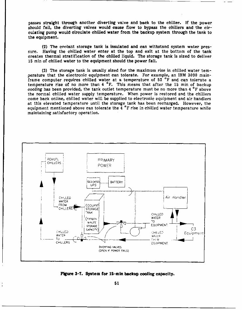
passes straight through another diverting valve and back to the chiller. If the powershould fail, the diverting valves would cause flow to bypass the chillers and the cir-culating pump would circulate chilled water from the backup system through the tank tothe equipment.
(2) The coolant storage tank is insulated and can withstand system water pres-sure. Having the chilled water enter at the top and exit at the bottom of the tankcreates thermal stratification of the chilled liquid. The storage tank is sized to deliver15 min of chilled water to the equipment should the power fail.
(3) The storage tank is usually sized for the maximum rise in. chilled water tem-perature that the electronic equipment can tolerate. For example, an IBM 3090 main-frame computer requires chilled water at a temperature of 52 OF and can tolerate atemperature rise of no more than 4 OF. This means that after the 15 min of backupcooling has been provided, the tank outlet temperature must be no more than 4 OF abovethe normal chilled water supply temperature. When power is restored and the chillerscome back online, chilled water will be supplied to electronic equipment and air handlersat this elevated temperature until the storage tank has been recharged. However, theequipment mentioned above can tolerate the 4 OF rise in chilled water temperature whilemaintaining satisfactory operation.
REMOTE PPIMARYCHILLERS POWER
DEDICATED - --- BATTERY
UPS f______
CI-LLED Air HandlerWATER
LKFROM A ',COOLANTICHILLER 47- 1 STORAGE'
TANK CHILLED
(FIFrEEN WATERMINUTE 1 ____--_ TO ___
STORAGE EQUIPMENT
CHILLED CAPACIY) / C3WAERCHI[ LED, Equipment
WATER W' A T -"R
C L " - F k( M _JEOUIPMENT
DIVERTING VALVES(OPEN IF POWER FAILS)
Figure 3-7. System for 15-min backup cooling capacity.
51

(4) By oversizing the storage tank, the rise in chilled water temperature can beminimized. Another strategy involves installing a second tank on the return side of thechiller. With this arrangement, when the chiller comes back on-line, the warm returnwater passes through the chiller before being supplied to the equipment and air hand-lers. The storage strategy used depends on the criticality of the mission, cost con-straints, and the chilled water temperature requirements of the electronic equipment.
(5) The uninterrupted power supply (UPS) is dedicated to the backup system. TheUPS detects a chiller power outage and sends power to the circulating pump and controlsas soon as the primary power fails and the diverting valves are closed. If the chillerserving the C31 room is in a different building and/or on a different circuit than the C 31room, special wiring is required, or the coolant temperature and/or flow rate should bemonitored instead.
(6) If the chiller is located near the C 3 1 room, the storage system controls consistof the motorized diverting valves and the UPS serving the pump, valves, and airhandlers. The controls must be EMP-protected, and all penetrations caused by chilledwater piping or control wires must be treated. The additional sensors and controls re-quired when the chiller is located remotely add to the cost of the backup cooling system,as well as the EMP protection. The extra controls also add to the complexity of thebackup system and therefore may have an impact on backup reliability.
(7) The circulating pump is sized for the backup circulating loop pressure drops.It is placed near the bottom of the coolant storage tank for net positive suction head(NPSH).
(8) Packaged electronic equipment chillers are available with "built-in" coolantstorage systems that deliver backup cooling to equipment should the primary power fail.These storage modules are physically attached to the liquid chillers, which are locatedwithin the C 31 room. The storage modules are available only for small liquid chillers incapacities ranging from 2.5 to 15 tons. The storage modules range in cost from $250 to$700/chiller ton, depending on the size of the chiller. It should be noted that while thestorage tanks are generally reliable, some designers avoid locating them inside the C31room due to the potential damage to electronic equipment should the tank leak.
b. Principal Applications. The main application for this backup system is to providea minimum of 15 min backup cooling should the power fail and normal chiller operationslose power. Coolant must be maintained to the critical C3I equipment.
c. Advantages. The clearcut advantage is the 15 min backup cooling should a powerfailure occur, which allows mission-critical operations to continue.
d. Disadvantages. Since chilled water flows through the coolant storage tank, higherpressure drops result, which require larger pump sizes. Also, after a power failure, thechiller must provide cooling while simultaneously recharging the storage tank. Thus, thechiller must be sized to handle the additional load imposed by storage recharging.
3-6. Piping System Components
Many system components can be used in a piping system, ranging from temperaturegauges to automatic air vents, and check valves to double-suction centrifugal pumps.This paragraph concentrates on the three main components used in typical chilled-waterpiping applications: piping, valves, and pumps.
52
a. Piping. Water piping can be divided into three main materials: steel (black andgalvanized); wrought iron (black and galvanized); and copper (soft and hard). Lesscommon materials are iron and steel alloys, copper alloys, nickel and nickel alloys, andnonmetallic pipe. The properties of these materials are either not suitable or not cost-effective for water piping.
(7) Steel.
(a) Description. This material is usually black or galvanized. Galvanized pipe ishot-dipped zinc-coated steel pipe and reduces the potential for corrosion.
(b) Principal AppLeation. Steel pipe is one of the most commonly used materialsin piping systems. Schedule 40 black steel is usually used for chilled-water, coolingtower, or refrigerant applications. In C31 applications where underground piping isnecessary, a galvanized coated steel pipe can be used effectively to prevent externalcorrosion. Internal corrosion is not a factor in a closed-loop piping system as long as thewater has been treated properly.
(c) Sizes. While normal pipe sizes range from 1/8 to 12 in. diameter, standardpipe sizes of up to 26 in. (od) are available.
(d) Cost. Based on 4-in.-diameter, schedule 40 pipe threaded with couplings andhangers, the cost for black steel is $9/in ft (material only) or $23/lin ft (installed); thecost for galvanized steel is $10/lin ft (material only) or $24/lin ft (installed).
(e) Advantages.
(i) The chief advantage of steel pipe is its superior strength. Steel pipe has ahigher tensile strength than any other standard construction material. In long verticaland horizontal runs, the structural strength and rigidity of steel pipe permit installationwith minimum supports.
(ii) Steel also has very little sensitivity to fluctuations in temperature. Copper,for instance, expands about 50 percent more than steel across the temperature spectrumof 20 to 200 OF.
(iii) Steel pipe has proven reliable for up to 70 years. In many old buildingsdemolished in recent years, steel pipe was found to be in excellent shape and functioningwell.
(f) Disadvantages. Steel is not very flexible for use in piping runs that requiresiight bending around obstacles, thus preventing a straight run. Ungalvanized steel pipeused in corrosive conditions will corrode over time.
(2) Wrought Iron.
(a) Description. Wrought iron is either black or galvanized.
(b) Principal Applications. Wrought iron can be used for chilled water, coolingtowers, and refrigerants. Galvanized wrought iron can be used for underground waterpiping.
(c) Sizes. Normal wrought iron pipe is 1/4 to 12 in. diameter.
53

(d) Cost. Based on a 4-in. pipe, the cost of wrought iron pipe ranges from $18 to$28/In ft installed.
(e) Advantages. The cost of wrought iron is relatively inexpensive comparedwith steel and copper.
(f) Disadvantages. Wrought iron is very hard. This property makes it susceptibleto metal fatigue if constant vibration of water hammer occurs. Wrought iron is alsoheavier than steel and copper and, as such, has a slightly higher installation cost.
(3) Copper.
(a) Description. There are four main types of copper pipe: K, L, M, andDWV. Type K has heavy walls and is available in hard and soft temper. Type L hasmedium walls and also is available in hard and soft temper. Type M has light walls and isavailable in hard temper only. Type DWV has light walls and also is available in hardtemper only.
(b) Principal Applications. Types K and L are commonly used in chilled-waterapplications. Copper pipe is usually installed when smaller diameter pipe is necessary.Large diameter copper pipe (above 4 in.) is extremely expensive and is not normally usedexcept in special cases or when other types are not available.
(c) Size. For each type listed above, typical diameters range from 1/4 to 8 in.
(d) Cost. These costs are based on 4-in.-diameter copper pipe. Type K, L, M,and DWV copper pipe range from $38/lin ft to $28/lin ft installed, and from $14/lin ft to$7/lin ft for material only.
(e) Advantages. Copper pipe is very resistant to corrosion. Also, in smallerdiameters, copper is very flexible. For example, it can be used when installing a ceiling-hung fan coil in a crowded ceiling where there are many obstacles. Steel pipe wouldrequire many elbows to achieve a fan coil.
(f) Disadvantages. Copper is very expensive compared with steel and wroughtiron pipe.
b. Valves. The four main types of valves used in HVAC applications are: (1) gate, (2)globe, angle, or "Y," (3) check, and (4) butterfly. Although other types of valves are usedin piping systems, these four are the most common. Water valves are usually made ofbrass, bronze, iron, or steel, and usually have working pressures of 125 psig or 150 per-cent of the system operating pressure, whichever is greater.
(1) Gate Valves.
(a) Operation. Figure 3-8 shows a typical rising stem gate valve. A gate valveis intended for use as a stop valve. It gives the best service when used in the fully openor fully closed position. With the valve wide open, the wedge or disk is lifted entirely outof the fluid stream, thus providing a straight flow area through the valve.
(b) Principal Applications. A typical location for gate valves Is close to thechiller or air handler equipment to permit Isolation. This arrangement enables the equip-ment to be serviced without having to drain or shut down the system.
54

(c) Sizes. Typical gate valves are 1 to 12 in. diameter; however, much largervalves can be obtained if needed. The 1-1/2-in. and smaller gate valves are usuallybronze, whereas 1-1/2 to 2-1/2-in. gate valves can be bronze or cast iron. The 2-1/2-in.and larger gate valves are usually cast iron.
(d) Cost. Based on a 4-in. outside screw and yoke (OS&Y), threaded, iron body,class 125 lb, an installed gate valve is approximately $335, and material only is $260.
(e) Advantages. When gate valves are used in the fully open condition, there isless turbulence and obstruction to flow than with other valves. This results in a lowerpressure drop than with other valves.
(f) Disadvantages. Gate valves cannot be used for throttling flow except in anemergency. Vibration, chattering, seat erosion, very high pressure drops, and widevariations in pressure drop would result if these valves were used for throttling.
(2) Globe, Angle, and "Y" Valves.
(a) Operation. Figures 3-9 through 3-11 show typical globe, angle, and "Y"valves, respectively. These three valves are grouped together since they have the samebasic design, use, and construction.
(b) Principal Applications. These valves are used primarily for throttling serviceand allow close regulation of flow. They can be used for shutoff and balancing but arenot ideal for this purpose. An angle valve can be used in a piping elbow, thus eliminatingthe need for an elbow.
RISING STEM(OUTSID SCREWAND0 Y0o) IANoWHEEL
(ON$ NOT RISeWITH STEM)
BOLTEDGLAND
BOLTEDBONNET
SOLID WEDGE
FLOW
FLANGEDENDS
Figure 3-8. Gate valve.
55

(c) Sizes. Typical valves range from 1/8 to 12 in.; however, larger sizes may beobtained. The 1-1/2-in. and smaller valves are usually bronze. When 2 to 3 in., thevalves can be bronze or cast iron. Four-inch and larger valves are usually cast iron.
(d) Cost. Based on a 4-in. diameter, OS&Y, class 125, threaded iron body, atypical globe valve costs approximately $600 installed and $500 for material only.
(e) Advantages. Unlike gate valves, globe, angle, and "Y" valves can be used forregulating flow as well as for shutoff.
(f) Disadvantages. In the full open position, globe valves create more turbulenceand friction drop than gate, angle, and "Y" valves. Gate valves are more suitable foroperation in the fully open position.
(3) Check Valves.
(a) Operation. Figures 3-12 and 3-13 show two basic types of check valves--swing and lift.
(i) The swing check valve can be used in a horizontal line. It can also be usedin a vertical line for upward flow. The flow through the swing check is in a straight lineand without restriction at the seat. Swing checks are generally used in combination withgate or butterfly valves.
(ii) The lift check operates much like a globe valve. The disk is seated by back-flow, or by gravity when there is no flow, and is free to rise and fall, depending on thepressure under it. The lift check is used only in horizontal piping, usually in combinationwith globe, angle, or "Y" valves.
HANOWHEEL(RISES WITH STEM) RISING STEM
(INSIDE SCREW)
PACKING NUTWITH GLAND
SCREWED UNIONRING BONNET
PLUG TYPE DISK
SCREWEDENDS
FLOW
Figure 3-9. Globe valve.
56
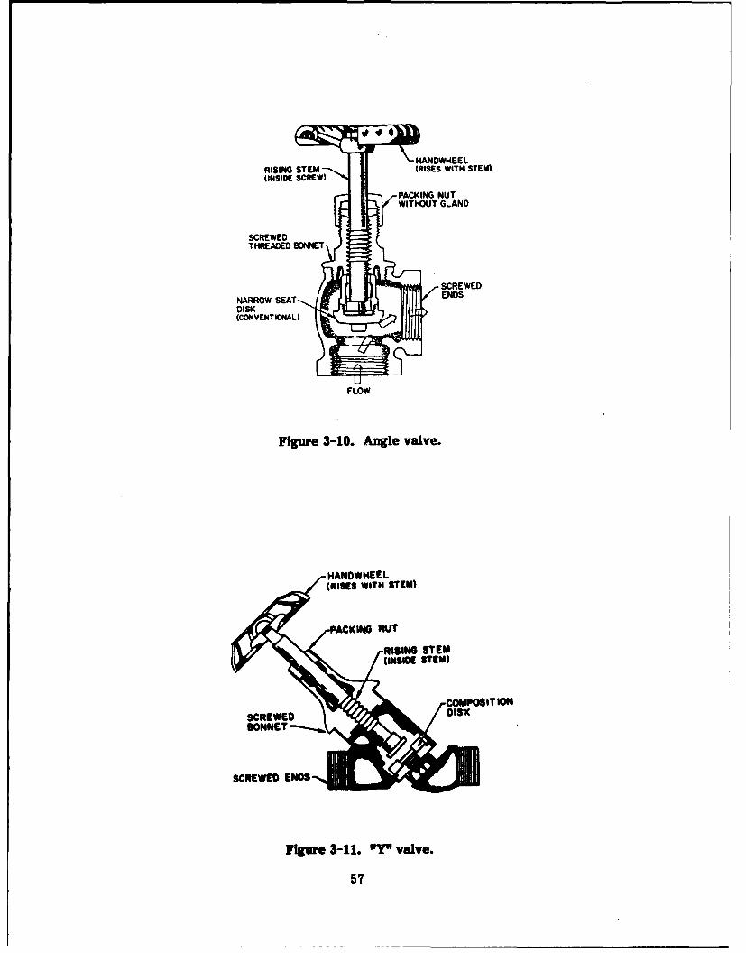
I4ANDWHEELRISING STEM (RISES WITH STEM)IINSIDE SCREW)
PACKING NUTWITHOUT GLAND
SCREWED
DISK(CON VENTION4AL)
FLOW
Figure 3-10. Angle valve.
I4ANOWNEEL(RISES WITH $TIEM)
CKING4 NUT
SCREWED DIS0K
Figure 3-11. "Y" valve.
57

FLOANGE
FLOW C *C
Figure 3-13. Lit check valve.
58EWDUNO

(b) Principal Applications. Lift (also known as nonslamming or silent) checkvalves are used in discharge connections for pumps, except for recirculating pumps, andare installed where required or recommended by the manufacturer of the connectedequipment.
(c) Sizes. Typical check valves range in size from 1/8 to 12 in. diameter. The 1-1/2 in. and smaller check valves are usually bronze, whereas 2- to 3-in. valves can bebronze or cast iron. Check valves 4 in. and larger are usually cast iron.
(e) Cost. A 4-in., 125-lb, threaded, iron body swing check valve is $270 installedand $200 for material only. Silent check valves are $210 installed and $105 for materialonly.
(e) Advantages. The clear advantage is backflow prevention.
(f) Disadvantages. If a check valve is installed in a piping system where it is notnecessary, pressure drop results.
(4) Butterfly Valves.
(a) Operation. A butterfly valve can operate as a stop valve or a throttlingvalve. Figure 3-14 shows a typical butterfly valve.
(b) Principal Applications. The use of butterfly valves is rapidly increasing forshutoff, throttling, and balancing of chilled-water flow applications. They may also beused in "tight" applications where space is limited.
(c) Sizes. In overall size, butterfly valves are generally smaller than gate orglobe valves. Typical butterfly valve diameters range from 1/8 to 12 in.
(d) Cost. Based on a 4-in. iron body, a butterfly valve costs about $150 installedand $75 for material only.
(e) Advantages. Butterfly valves can be easily turned by hand. Also, they arevery versatile since they can regulate, throttle, or balance flow. They are less costly
Figure 3-14. Butterfly valve.
59
than comparable valves, and better for use in tight areas where piping space is a pre-mium since they take up very little space.
(f) Disadvantages. Butterfly valves have higher pressure drops in the fully openposition than gate valves and occasionally they do not seat as well as gate valves in theshutoff mode.
c. Pumps. Centrifugal pumps are used in most heating and air-conditioning appli-cations. Other types of pumps such as reciprocating, rotary, and jet are not as wellsuited for these applications. Therefore, this discussion is limited to centrifugal pumps.Centrifugal pumps have fewer moving parts than other pumps, making them morereliable. Also, they are usually less expensive and require less space. In addition, centri-fugal pumps cover a larger range of operating speeds than other types.
(1) Several factors are involved in selecting a pump, including:
" The liquid type
" System head curve
" Pertinent local conditions surh as continuous or intermittent service
" Indoor or outdoor operation
" Range of capacity requirement
" Range of pressure requirement
" Temperature
" Type of drive
" Number of pumps desired and percent of standby required for emergencyoperation
" Electrical service characteristics and controls.
Each pump has an electric motor with a nameplate horsepower rating not less than theactual break horsepower required to drive the pump at any head from zero to shutoff.Continuous duty pumps are used for 24-hr facilities like C °I rooms and should be rated at100 percent capacity.
(2) In C3 I applications, multiple parallel pumps are generally installed to providethe required redundancy. Figure 3-15 shows a typical parallel pumping arrangementwhen pumps are connected to the same header.
(3) The pumps selected to run in parallel must have shutoff heads in excess ofthe operating head when operating in parallel. If the pumps are supplying underfloorchilled water to water-cooled equipment, three parallel pumps powered by a UPS arecommonly used.
(4) The use of multiple pumps operating in parallel Is the most common methodof eliminating system overpressure, which occurs in controlled flow systems where coilsare equipped with two-way control valves.
60
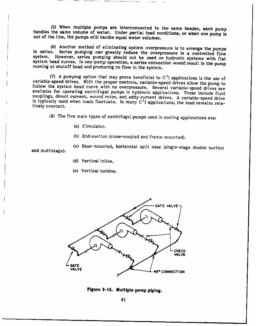
(5) When multiple pumps are interconnected to the same header, each pumphandles the same volume of water. Under partial load conditions, or when one pump isout of the line, the pumps still handle equal water volumes.
(6) Another method of eliminating system overpressure is to arrange the pumpsin series. Series pumping can greatly reduce the overpressure in a controlled flowsystem. However, series pumping should not be used on hydronic systems with flatsystem head curves. In one-pump operation, a series connection would result in the pumprunning at shutoff head and producing no flow in the system.
(7) A pumping option that may prove beneficial to C31 applications is the use ofvariable-speed drives. With the proper controls, variable-speed drives allow the pump tofollow the system head curve with no overpressure. Several variable-speed drives areavailable for operating centrifugal pumps in hydronic applications. These include fluidcouplings, direct current, wound rotor, and eddy-current drives. A variable-speed driveis typically used when loads fluctuate. In many C 31 applications, the load remains rela-tively constant.
(8) The five main types of centrifugal pumps used in cooling applications are:
(a) Circulator.
(b) End-suction (close-coupled and frame-mounted).
(c) Base-mounted, horizontal split case (single-stage double suctionand multistage).
(d) Vertical inline.
(e) Vertical turbine.
VALVE " 450 CONNECTION
Figure 3-15. Multiple pump piping.
61
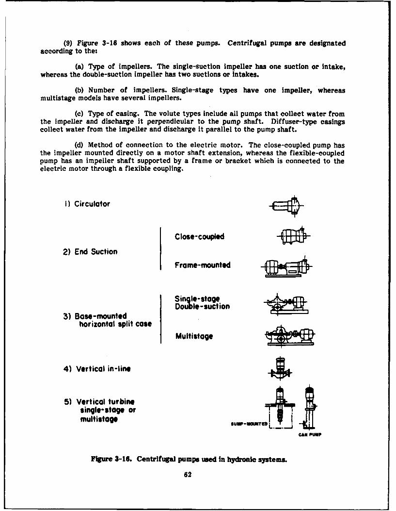
(9) Figure 3-16 shows each of these pumps. Centrifugal pumps are designatedaccording to the:
(a) Type of impellers. The single-suction Impeller has one suction or intake,whereas the double-suction impeller has two suctions or intakes.
(b) Number of impellers. Single-stage types have one impeller, whereasmultistage models have several impellers.
(c) Type of casing. The volute types include all pumps that collect water fromthe impeller and discharge it perpendicular to the pump shaft. Diffuser-type casingscollect water from the impeller and discharge it parallel to the pump shaft.
(d) Method of connection to the electric motor. The close-coupled pump hasthe impeller mounted directly on a motor shaft extension, whereas the flexible-coupledpump has an impeller shaft supported by a frame or bracket which is connected to theelectric motor through a flexible coupling.
I) Circulator
Close-coupled -- 0
2) End Suction
Frame-mounted -Ma
Single-stageDouble-suction
3) Base-mountedhorizontal split case
Multistage_
4) Vertical in-line
5) Vertical turbinesingle-stage ormultistage OuN,-OW - ._
CAN PUMP
Figure 3-16. Centrifugal pumps used in hydronlo systems.
62
(e) Mounting position. Pump motors can be mounted either horizontally or
vertically.
d. Summary of Pump Types.
(1) Circulator Pumps.
(a) Operation. Circulator pumps are usually single-suction, with one impeller, avolute type casing, and a flexible-coupled horizontal motor.
(b) Principal Applications. Some typical applications are residential hydronicsystems, domestic hot-water recirculation, and multizone circulation. These pumps arealso used in small chilled-water applications.
(c) Sizes. Circulator pumps range in size from 1/4 to 3 HP.
(d) Cost. A 1/2-HP circulating pump costs approximately $700 for material and$900 installed.
(e) Advantages. Circulator pumps are ideal for small pumping applicationswhere low capacities and heads are needed.
(f) Disadvantages. Circular pumps cannot be used for medium to large cap-acities. The range of pumping capacities and heads is relatively small.
(2) End-Suction Pumps (Close-Coupled, Frame-Mounted).
(a) Operation. The two basic types of end-suction pumps are close-coupled andframe-mounted. Both have single suction, one or two impellers, a volute-type casing,and a horizontal motor mounting position.
(b) Principal Applications. Some typical end-suction pump applications includecooling towers, condenser water, chilled water, hot water, boiler feed water, condensatereturn, booster, and irrigation.
(c) Sizes. Capacities are to at least 3500 gallons per minute (GPM) and heads to500 ft. Typical discharge is 4 to 8 in. in diameter.
(d) Cost. A typical 10-HP end-suction, frame-mounted, single-stage pump costsapproximately $2700 for material only. The installed cost is $4200.
(e) Advantages. End-suction pumps are ideal for chilled-water applications thatare too large for a circulator pump to handle.
(f) Disadvantages. Like the circulator pump, end-suction pump capacities andheads are relatively low compared with other centrifugal pumps.
(3) Base-Mounted, Horizontal Split-Case Pumps (Single-Stage Double-Suction andMultistage Double-Suction).
(a) Operation. Base-mounted horizontal split-case pumps are either single-stage, double-suction, or multistage double-suction. They have a volute-type casing anda flexible coupled, horizontal motor.
63

(b) Principal Applications. Typical applications include cooling towers, con-denser water, chilled water, hot water, boiler feed, condensate return, irrigation, andfire protection. These pumps are commonly used in large HVAC applications.
(c) Sizes. Discharge sizes are typically 1 to 14 in., and can be up to 35 in. indiameter. Capacities are to 70,000 GPM, and heads to 500 ft.
(d) Cost. The typical cost for a 10-HP single-stage double-suction pump isabout $3400 for material only and $5400 installed.
(e) Advantages. Base-mounted horizontal split-case pumps are ideal for largeapplications. They are more reliable and easier to maintain than end-suction pumps. Thepump can be maintained or repaired without disturbing the piping.
(f) Disadvantages. Horizontal split-case pumps are not very efficient for smallcapacities.
(4) Vertical Inline Pumps.
(a) Operation. Vertical inline pumps are usually single-suction with one im-peller. They have a vertical motor position and can be flexible or close-coupled.
(b) Principal Application. Typical applications are for cooling towers, condenser
water, .hilled water, hot water, boiler feed, and condenser return.
(c) Sizes. Typical discharge sizes are 1 to 5 in. diameter.
(d) Cost. A typical inline 1-HP vertical pump costs $700 for material and $900installed.
(e) Advantage. Vertical inline pumps are ideal for small applications wherewater circulation is continuous.
(f) Disadvantage. A disadvantage of the vertical inline pump is the relativelysmall capacities compared with end- and double-suction pumps.
(5) Vertical Turbine Pumps.
(a) Operation. Vertical turbine pumps are usually single-suction with 1 to 20impellers. They have a diffuser-type casing and a flexible-coupled vertical motor.
(b) Principal Applications. These pumps are used in chilled water, hot water,boiler feed, condensate return, and booster applications. They are also commonly used incooling towers and fire protection services, where high capacities and heads are needed.
(c) Sizes. Typical sizes range from 6 to 57 in. discharge diameter with cap-acities to 40,000 GPM and heads to 1000 ft.
(d) Cost. A 10-HP vertical turbine pump costs about $4000 for material only and$6000 installed.
(e) Advantage. Vertical turbine pumps are very effective in applications wherelarge heads and capacities are necessary.
(f) Disadvantage. They are not very efficient for smaller applications.
64
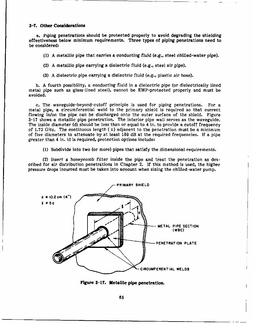
3-7. Other Considerations
a. Piping penetrations should be protected properly to avoid degrading the shieldingeffectiveness below minimum requirements. Three types of piping penetrations need tobe considered:
(1) A metallic pipe that carries a conducting fluid (e.g., steel chilled-water pipe).
(2) A metallic pipe carrying a dielectric fluid (e.g., steel air pipe).
(3) A dielectric pipe carrying a dielectric fluid (e.g., plastic air hose).
b. A fourth possibility, a conducting fluid in a dielectric pipe (or dielectrically linedmetal pipe such as glass-lined steel), cannot be EMP-protected properly and must beavoided.
c. The waveguide-beyond-cutoff principle is used for piping penetrations. For ametal pipe, a circumferential weld to the primary shield is required so that currentflowing in/on the pipe can be discharged onto the outer surface of the shield. Figure3-17 shows a metallic pipe penetration. The interior pipe wall serves as the waveguide.The inside diameter (d) should be less than or equal to 4 in. to provide a cutoff frequencyof 1.73 GHz. The continuous length ( t) adjacent to the penetration must be a minimumof five diameters to attenuate by at least 100 dB at the required frequencies. If a pipegreater than 4 in. id is required, protection options include:
(1) Subdivide into two (or more) pipes that satisfy the dimensional requirements.
(2) Insert a honeycomb filter inside the pipe and treat the penetration as des-cribed for air distribution penetrations in Chapter 2. If this method is used, the higherpressure drops incurred must be taken into account when sizing the chilled-water pump.
PRIMARY SHIELD
.0 sJMETAL PIPE SECTION(WBC)
PENETRATION PLATE
CIRCUMFERENTIAL WELDS
Figure 3-17. Metallie pipe penetration.
65
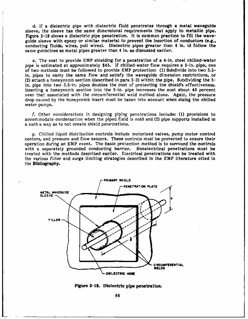
d. If a dielectric pipe with dielectric fluid penetrates through a metal waveguidesleeve, the sleeve has the same dimensional requirements that apply to metallic pipe.Figure 3-18 shows a dielectric pipe penetration. It is common practice to fill the wave-guide sleeve with epoxy or similar material to prevent the insertion of conductors (e.g.,conducting fluids, wires, pull wires). Dielectric pipes greater than 4 in. id follow thesame guidelines as metal pipes greater than 4 in. as discussed earlier.
e. The cost to provide EMP shielding for a penetration of a 4-in. steel chilled-waterpipe is estimated at approximately $45. If chilled-water flow requires a 5-in. pipe, oneof two methods must be followed to provide EMP protection: (1) Subdivide into two 3.5-in. pipes to carry the same flow and satisfy the waveguide dimension restrictions, or(2) attach a honeycomb section (described in para 2-3) within the pipe. Subdividing the 5-in. pipe into two 3.5-in. pipes doubles the cost of protecting the shield's effectiveness.Inserting a honeycomb section into the 5-in. pipe increases the cost about 40 percentover that associated with the circumferential weld method alone. Again, the pressuredrop caused by the honeycomb insert must be taken into account when sizing the chilledwater pumps.
f. Other considerations in designing piping penetrations include: (1) provisions toaccommodate condensation when the piped fluid is cold and (2) pipe supports installed ina such a way as to not create shield penetrations.
g. Chilled liquid distribution controls include motorized valves, pump motor controlcenters, and pressure and flow sensors. These controls must be protected to ensure theiroperation during an EMP event. The basic protection method is to surround the controlswith a separately grounded conducting barrier. Nonelectrical penetrations must betreated with the methods described earlier. Electrical penetrations can be treated withthe various filter and surge limiting strategies described in the EMP literature cited inthe Bibliography.
PRIMARY SHIELO
METAL PENETRATION PLATE
SLEEVE ,d
FILLER #
CIRCUMFERENTIALWELD$
DIELECTRIC HOSE
Figure 3-18. Dielectric pipe penetration.
66
Section III: SUMMARY EVALUATION
3-8. How To Use the Evaluation Table
Table 3-1 ranks each piping configuration for all criteria except the 15-min backupcooling configuration. Although other methods can provide backup cooling, the chilled-water storage system is preferred due to its cost, reliability, and timeliness of switch-over.
a. Table 3-1 is divided into two sections: piping configurations outside the C 3I room
and those inside the C3 I room. The three piping configurations outside the C3I room are:
(1) A central chiller serving C3I room, C 3I building, and other buildings,
(2) A chiller serving C3I room and C 3I building,
(3) A dedicated chiller serving the C3I room and another serving the rest of thebuilding.
b. The piping configurations inside the C 31 room are divided into the following threesubsets:
(1) Subset I--
(a) C 3I room inside loop piping.
(b) C3 I room perimeter loop piping.
(2) Subset 2--
(a) Oversized piping.
(b) Redundant piping.
(3) Subset 3--
(a) Dedicated chiller for direct equipment cooling.
(b) Chiller tempering loop for direct equipment cooling.
c. Each of the three subsets are discussed and ranked separately. A comparisonbetween subsets would not be applicable since the three configurations serve differentpurposes.
d. Each configuration is ranked using the criteria listed in Section I. These rankingsare qualitative, with a black circle representing a high ranking in the table, a gray circledenoting a medium ranking, and a white circle indicating a low ranking. A low rankingsimply means that other configurations are more suitable for a specific criterion, and notthat the configuration is a poor choice.
87
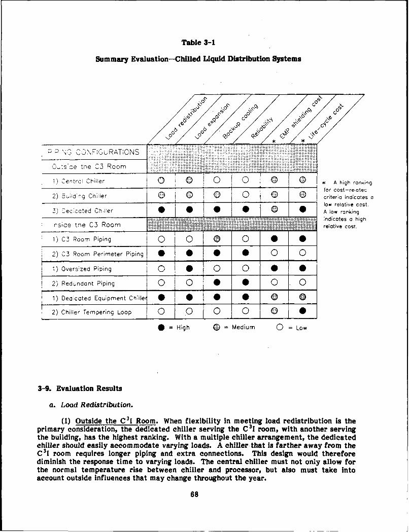
Table 3-1
Summary Evaluation-Chilled Liquid Distribution Systems
0 C,
:-'GC.N,=!-uRAT'ONS
0 ,tsze the C3 Room
1) Central Chiller 0 0 0 * A high rankingfor cost-relotec0uing Chiller 0 _ criteria indicates a
low relative cost.3) [,eclcoted Chiller 0 0 A low ranking
___________________________________ -- indicates a highinside tne C3 Room .. :... . .. :.. ..... relative cost.
1) C3 Room Piping 0 0 0 0 0 0
2) C3 Room Perimeter Piping 00 0
1) Oversized Piping O0 0 le 0
2) Redundant Piping 0 0 0
1) Deaicoted Equipment Chiller 0 0 0 0 0 0
2) Chiller Tempering Loop 0 0 0 0 0 0
•=High 0 Medium 0 =Low
3-9. Evaluation Results
a. Load Redistribution.
(1) Outside the C3I Room. When flexibility in meeting load redistribution is theprimary consideration, the dedicated chiller serving the C I room, with another servingthe building, has the highest ranking. With a multiple chiller arrangement, the dedicatedchiller should easily accommodate varying loads. A chiller that Is farther away from theC3I room requires longer piping and extra connections. This design would thereforediminish the response time to varying loads. The central chiller must not only allow forthe normal temperature rise between chiller and processorp but also must take intoaccount outside influences that may change throughout the year.
68

(a) If the load does change at the equipment, it may take some time for thechiller to react and temperature fluctuations may result as the chiller seeks the correctlevel. This situation could cause internal condensation from too low a water temperatureor shutdown if temperature raises too much.
(b) If the total C 31 room load remains relatively constant while the locations ofthe loads within the room change, all three cases would be about equal. This problemwould be handled by the air distribution system.
(2) Inside the C 3 1 Room. When flexibility in meeting load redistribution is theprimary consideration, piping around the perimeter has the highest ranking. Perimeterpiping offers high flexibility since there are fewer underfloor obstructions than if thepiping loops were run under the C 31 floor. For example, if a load redistribution causesthe need to relocate a room air handler, the existing piping can be capped (for future use)inside the room near the wall penetration point. The new piping can penetrate the C 31wall near the new air handler location. There will be relatively little piping obstructionunder the floor. If the load redistribution does not require repiping, all cases will beabout equal since the redistribution will be done by the air distribution system.
(a) Oversized piping or redundant piping rank relatively equal when consideringload redistribution. Either piping configuration could be used with the same results.Thus, both oversized piping and redundant piping configurations are given a mediumranking.
(b) For dedicated chillers or tempering loops, when there is a constant total C31room load, both cases are relatively equal. However, if the total load fluctuates, thededicated equipment chiller would have the best ranking since it would be more res-ponsive to temperature fluctuations.
b. Load Expansion.
(1) Outside the C31 Room. When flexibility in meeting load expansion is theprimary consideration, the dedicated chiller serving the C31 room, with another servingthe building, has the highest ranking. For the same reason as stated for load redistri-bution, a dedicated equipment room chiller is much more responsive to changing roomrequirements. Not only is the central building chiller more difficult to connect initially,but future alterations for additional hardware are costly in terms of both time andmoney. Rigid piping connections, as well as intricate adjustments in flow rates andpressure, must all be changed when new equipment is added.
(2) Inside the C 31 Room. As in the case for load redistribution, perimeter pipinghas the highest ranking where flexibility in load expansion is concerned. If an additionalair handler needs to be connected, the connections can easily be piped from the peri-meter loop closest to the new location.
(a) Oversized piping has the highest ranking for load flexibility since only athrottling valve adjustment would be required to increase chilled water capacities.
(b) A dedicated equipment chiller has a higher ranking over a tempering loopconfiguration. The dedicated chiller requires fewer control adjustments and, therefore,accommodates load expansion better than a tempering loop.
69
c. 15-Min Backup Cooling Capacity.
(1) Outside the C 31 Room. When the capacity to provide 15 min of backup coolingis the primary consideration, the dedicated chiller serving the C31 room with anotherserving the building, has the highest ranking. If the chiller serving the C I room is in adifferent building or a considerable distance away from the C3I room, special wiring isrequired to achieve the necessary feedback to the backup control system.
(2) Inside the C 31 Room. A perimeter piping loop has a higher ranking than anunderfloor piping loop inside the C3 I room. The backup cooling system will occupyvaluable space if it is located under the floor. If it is located around the perimeter, notonly will less underfloor space be taken, but the backup system can also be inspectedeasily.
(a) A redundant piping arrangement has a higher ranking than an oversized pipingconfiguration. Since chilled water flows continuously through the backup loop, it will bemore costly to pump water through a larger pipe than a smaller one. With redundantpiping, one of the two pipes can be used, each smaller than the oversized pipe.
(b) A dedicated equipment chiller has a higher ranking than a tempering loop.Since the power to the chiller needs to be monitored in the 15-min backup case, a dedi-cated chiller would require less control wiring since it would be closer to the backupconfiguration.
d. Reliability.
(1) Outside the C3 I Room. When reliability is the primary consideration, a dedi-cated chiller serving the C'I room, with another serving the building, has the highestranking. This case provides for additional chillers and, thus, increases the reliability ofmaintaining the supply of chilled water to the C 31 room. An ideal setup would have theC3 I room chillers backed up by the building chillers.
(2) Inside the C3 I Room. A perimeter piping chilled-water loop has a higherrating than inside room loop. Since perimeter piping can be inspected easily, a higherdegree of reliability is offered.
(a) The redundant pipe configuration has a higher ranking than the oversizedpipe. Since the redundant pipe configuration has an "extra" pipe, the reliability isbetter. If some component were to malfunction in oversized piping, there would be noredundancy.
(b) A dedicated equipment chiller is ranked higher than a tempering loop. Sincethe dedicated equipment chiller requires fewer control setups than a tempering loop, itwill have a slightly higher degree of reliability.
e. Least Cost for EMP Shielding.
(1) Outside the C3I Room.
(a) When least cost for EMP shielding is the primary consideration, all threeconfigurations are basically equal. In each configuration, chilled water and ducting willpenetrate the C3 I room shield. If there are no plans for personnel to occupy the C3Iroom, then the piping would be the only HVAC penetrations since ducts to supply airwould not be required.
70
(b) If the entire C 3 I building is EMP-protected and the chiller is remotelylocated, then the chiller will need to have EMP shielding. In this case, the building, ordedicated, chiller will have a higher ranking than a central chiller.
(2) Inside the C3 I Room. Piping inside the computer room has a higher rankingthan the perimeter piping configuration. Perimeter piping requires either a larger shieldor many penetration points. If the shield is exterior to the C 3I room and the ?erimeterloop, it will need to be much larger and, of course, more expensive. If the C I room isshielded, the perimeter pipe penetrations will require shielding. This will also raise theprice considerably.
(a) Oversized piping is ranked higher than redundant piping. The cost to pene-trate an EMP shield with one large pipe having a honeycomb insert is some 30 percentless than penetrating the shield with two smaller pipes without honeycomb inserts.Taking into account the larger pump needed to accommodate the additional pressuredrops created by the honeycomb insert, and the added maintenance for the honeycombinsert, the two methods are fairly equivalent.
(b) A dedicated chiller has basically the same rating as a tempering loop. Inboth cases, piping penetrates the shield and is approximately the same size. Therefore,the EMP cost will be the same.
(c) If the entire C 31 building is shielded, the EMP shielding cost will not be aconsideration for these cases inside the C3I room.
f. Lowest Life-Cycle Cost.
(1) Outside the C3I Room.
(a) When the lowest life-cycle cost is the primary consideration, a dedicatedchiller serving the C3I room, with another serving the C3I building, has the highestrating. In this case, a high rating means a low life-cycle cost. Conversely, a low ratingindicates a high life-cycle cost.
(b) A remote chiller would have to be run 24 hr/day to meet the requirements ofa C3 I room. Running a larIe chiller for long periods of time to supply the relativelysmall cooling needs of the C I room is inefficient and expensive. With a building chiller,the energy consumption of the pumps alone may exceed the total energy use of a dedi-cated chiller.
(2) Inside the C 3 I Room. The inside room loop is rated higher than the perimeterpiping loop. Since there is relatively no operating cost difference between the two cases,the initial cost is the basis for comparison. More piping will be required in the perimetercase (since the loop is much larger) than if the piping loop were inside the C 3I room.
(a) Oversized piping has a higher rating than the redundant piping configur-ation. A redundant piping arrangement will cost more than an oversized piping layout.
(b) A chiller tempering loop has a higher rating than a dedicated chiller. Thecost of a dedicated chiller is much greater than that of a tempering loop.
71

4 AIR-HANDLING UNITS
Section 1: GENERAL
This chapter evaluates design approaches for air-handling units capable of supplying airto the air distribution systems described in Chapter 2. The following criteria are used toevaluate each type of air handler:
1. Flexibility in meeting load redistribution.
2. Flexibility in meeting load expansion.
3. Precise humidity control.
4. Filtering of particulate matter.
5. Static electricity control.
6. Capacity to provide 15 min of backup cooling.
7. Reliability.
8. Least cost for EMP shielding.
9. Lowest life-cycle cost.
Some criteria do not apply to air-handling units. In these cases, "N/A" appears in theevaluation table listing the results of the ranking procedure.
4-1. Types of Air Handlers
a. Air-handling units are sold in a wide variety of sizes and capacities. Factory-assembled central station air handlers are available with supply air flow rates up to65,000 CFM, while field-erected units can supply air at more than 100,000 CFM. At theother extreme, individual fan coil units have air flows as low as 100 CFM. This reportconcentrates on the four main types of air-handling units used in C 3I rooms:
(1) Central station air-handling units.
(2) Chilled-water packaged units.
(3) Self-contained packaged units.
(4) Fan coil units.
b. In most practical applications, the C31 room will be served by a combination of theair handler types evaluated. For instance, a central station air handler will provideoutside air and dehumidification/humidification functions, and floor-mounted packagedunits will provide sensible cooling. The dew point control system mentioned in Chapter3, and further described in this chapter, is an example of such a system.
72

Section 11s SYSTEM DESCRIPTION
4-2. Air Handlers for C 31 Rooms
a. Electronic equipment rooms often must have more than one type of air-handlingsystem to satisfy the redundancy, temperature, and humidity requirements of C Irooms. However, to be consistent with the subsystems approach used in these guidelines,each air-handling unit is described and evaluated separately.
b. The self-contained packaged unit differs from the other air handlers evaluated inthat it incorporates refrigeration equipment within the unit. C 3I room air is cooled byblowing it over a DX refrigerant coil. Due to the refrigeration equipment, the self-contained packaged units have a higher life-cycle cost than any of the other air handlersevaluated. Since none of the other air handlers have refrigeration equipment, self-con-tained packaged units cannot be compared equally on the basis of life-cycle cost. How-ever, the units are ranked under the other criteria.
4-3. Central Station Air-Handling Units
a. Operation.
(1) A general equipment arrangement for components of a typical central air-handling unit (AHU) is shown in Figure 4-1. Although the diagram indicates a built-upsystem, most of the components are available completely assembled by the manufactureror in subassembled sections that can be bolted together in the field. Figure 4-2 shows anactual central AHU.
REHEAT COILIF 13YPASSEXHAUST OR FS USED RETURN FANRELIEF DAMPERA
,
ORTuRI AIR IFR LBYLO MPER IISNOLTER
D - LO DPAI A REHEAT AF lt "" COIL C04 13 " HUM IIER
MINIMUM-- ML U U U , F ' -
OUTSINELIT ML DME ML M LM
FACE AND
BYPASSDAPERS €.___
/ USIDEAIR
DAMPER
/- F FD FDFSPL'-F REHEAT COIL FDAN
OUTSIDE AIR IF BYPASS
LOUVER IS NOT USED
FD : FLOOR DRAIN AUTOMATIC DAMPER, -'ML -MARINE LIGHT MANUAL DAMPER .
Figure 4-1. Equipment arrangement of a central air-handling unit.
73
r
Figure 4-2. Central air-handling unit.
(2) A central station AHU typically consists of:
(a) Return and supply fans.
(b) Automatic dampers.
(c) Relief openings.
(d) Return air dampers.
(e) Outdoor air intakes.
(f) Mixing plenum.
(g) Air filter section.
(h) Preheat coil.
(i) Cooling coil.
(j) Bypass section.
(k) Reheat coil section.
(1) Humidifier.
74

(3) The return air fan ensures that the proper volume of air returns from thespace. It also reduces resistance to the supply fan. The return air fan should handle aslightly smaller quantity of air than the supply air fan to ensure a positive pressure in theC I room.
(4) The supply air fan can be axial flow or centrifugal. Large systems usually arecentrifugal. The supply fans must be matched carefully with the return fans in VAVsystems to ensure proper distribution pressures. The basic central AHU can be designedto supply a variable or a constant air volume. It can supply the air for low-, medium-,and high-pressure air distribution.
(5) The automatic dampers can be arranged with opposing blade dampers for theoutdoor, return, and relief air streams. This design allows a very high degree of control.
(6) Relief openings for large facilities must be constructed similar to outdoor airintakes. The main difference is that they should have backdraft dampers to prevent highwind pressures or stack action from causing the air flow to reverse when the automaticair dampers are open.
(7) Return air dampers must accommodate the pressure drop across the damperplus the difference between the positive pressure-relief air plenum and the negativepressure in the outdoor air intake plenum. The positive pressure in the relief air plenumis a function of the static pressure loss through the exhaust or relief damper, the exhaustduct between the plenum and outside, and the relief louver. The negative pressure in theoutdoor air intake plenum is a function of the static pressure loss through the outside airlouvers, dampers, and ducts.
(8) Outdoor air intakes should have a minimum pressure loss of less than 0.10 in.of water. High-efficiency, low-pressure loss louvers that effectively limit carryover ofrain should also be used.
(9) Mixing plenums are provided to mix the outside and return air. Return airdampers should be set so that any deflection of air is toward the outside to maximizeturbulence and mixing. While opposed blade dampers offer better control, properlyproportioned parallel blade dampers are more effective than opposed blade dampers formixing air streams of different temperatures. Dampers must be arranged to achieveproper mixing, regardless of the final type and configuration. Otherwise, the preheatcoil will waste heat or the cooling coil may freeze.
(10) Air filter sections contribute much to system performance. A dirty filterincreases system resistance, diminishes air flow, and lowers the life of the fan equip-ment. Primary considerations with filters are selection and location. The filter must beeasily accessible for cleaning or replacement. A roller-type filter can be used thatautomatically rolls new filter media into place when the existing filter section becomesdirty.
(11) Preheat coils should be protected by filters, have wide fin spacing, and beaccessible for easy cleaning. The coils are usually heated with steam or hot water. Ifsteam it used, an& ;AlliLt distribution tube or integral face and bypass coils are prefer-able. If hot water is used, a constant flow recirculating pump should be used withparallel piping so that the coldest air will contact the warmest coil surface first.
(12) Cooling coils remove sensible and latent heat from the air. For close controlof room conditioning, as in C3 I rooms, a deep coil with spray or an air washer might be
75
required. A copper fin coil is required for sprays. Coil freezing can be a serious problemwith chilled water coils. Full-flow circulation of chilled water during freezing weatherdiminishes the chances of freezing. Antifreeze solutions or complete coil draining alsocan prevent coil freezing.
(13) The bypass sections mix air for a third time. At reduced internal loads, theroom thermostat opens the bypass damper, which permits return air to enter the bypasssection. At the same time, the face damper on the cooling section closes and reducesthe flow of cooled and dehumidified air. The temperature of the mixed air rises, andovercooling is prevented. Since there is a large pressure drop across the bypass damper,it has heavy leakage when closed. The apparatus dew point can be lowered to com-pensate.
(14) Reheat coil sections are used where it is essential to control temperature andrelative humidity accurately. Heating coils located in the reheat position, as shown inFigure 4-1, are often used for warmup, although a coil in the preheat position is pre-ferable. The reheat coils can be heated by hot water, steam, or electricity, with hotwater providing the highest degree of control.
(15) Steam grid humidifiers or recirculating sprays with dew point control usuallyare used for accurate humidity control. In this application, the evaporation heat shouldbe replaced by heating the recirculated water rather than increasing the size of thepreheat coil.
b. Principal Applications.
(1) Central systems are typically used in the following cases:
(a) Uniform loads--generally large areas with small external loads.
(b) Multiple systems in large areas--very large facilities such as factories,hangars, and hospitals may require multiple central stations.
(c) As a primary source of conditioned air for other subsystems such as VAVsand mixing boxes.
(2) The central station equipment is located outside the computer room, usually ina basement, penthouse, or service area. It can be adjacent to, or a considerable distanceaway from, the primary heating and refrigeration equipment.
(3) In the dew point control scheme described in the section on chilled-waterpackaged units, the central station supplies cool air at the room dew point temperature,while the room AHUs supply sensible cooling only. In this case, a sprayed coil dehu-midifier is used in the central unit to make maximum use of recovered heat to warm theair so that it will accept moisture. Also, the air is saturated or nearly saturated uponleaving the unit and allows accurate control of dew point temperature when dehu-midifying.
c. Sizes. A central AHU typically ranges from about 3000 CFM to 65,000 CFM.
d. Cost. The equipment costs of a central chilled water AHU range from $400/tonfor a 7-ton unit to $260/ton for a 115-ton unit. Installed costs range from $550/ton for a7-ton unit to $350/ton for a 115-ton unit.
76
e. Advantages.
(1) In central station supply systems, components with larger capacities can beused than in self-contained room air-conditioning equipment. Also, since the equipmentis not located within the computer room, a central station AHU can be used with agreater variety of choices in air-conditioning design and arrangement.
(2) No C31 room floor space is required, and virtually all servicing andmaintenance operations can be performed in areas specifically devoted to air-conditioning equipment.
(3) Roller-type filter mechanisms can be used that automatically roll new filtermedia into place when the existing filter material becomes dirty. This featureeliminates downtime for changing the filters and minimizes the possibility of operatingthe AHU with inadequate filtration.
f. Disadvantages. Since the AHU is outside the C 3I room, physical security islessened. In addition, large-diameter ducts penetrate the C 31 shield, thus increasing theEMP shielding cost. If the system is used for other operations, the setpoints must bealtered for them. Also, a central station AHU usually serves overhead ducted supplysystems. As discussed in Chapter 2, overhead ducted supplies may not be as flexible inaccommodating load redistribution or expansion as room AHUs would be.
4-4. Chilled-Water Packaged Units
a. Operation.
(1) Figure 4-3 shows a typical arrangement for a chilled-water packaged unit.Components common to most chilled-water packaged units include: a filter rack, chilledwater coil, humidifier, reheat coil, fan, and fan motor. Chilled-water packaged unitsdesigned for electronic equipment room environments are built with a higher level ofperformance and reliability than conventional packaged units designed for comfortapplications. These units are usually mounted on the raised floor of the C3I room.However, in smaller cooling capacity ranges, they may be hung from the ceiling. Floor-mounted units are available with both upward and downward air flow patterns.
(2) Downward-flow, floor-mounted, chilled-water packaged units typically usehorizontal filter racks located at the top. Upward-flow units are arranged with verticalfilters located on the front face. Ceiling-hung chilled-water packaged units have eithervertical filters in the air intake section or horizontal filters located inside the air intakeceiling panels. Filters generally can be replaced without interrupting unit operation.
(3) Most units are furnished with disposable filters that have ASHRAE Standard52-76 dust spot efficiencies ranging between 35 and 60 percent. ASHRAE recommends afiltration efficiency of 45 percent for electronic equipment room applications.
(4) It should be noted that floor-mounted, chilled-water packaged units generallyuse a free return system and, therefore, do not introduce or filter outside air required forminimum ventilation and positive pressurization. Outside air requirements must besatisfied by a separate duct, fan, and filter system or by one air handler that serves theentire C3[ room area, such as a central station air handler. The outside air ductpenetrates the EMP shield, and therefore, precautions must be taken to protect theeffectiveness of the EMP shield. These precautions were addressed in Chapter 2.
77
FILTER
COOLINGCOIL
BYPASSREHEAT
HUMIDIFIER
RAISED FANFLOOR
Figure 4-3. Chilled-water packaged unit. (Source: ASHRAE 1987 HVAC Systemsand Applications Handbook. Used with permission.)
(5) Most chilled-water packaged units are equipped with either a vertical or A-frame chilled-water coil. Since C3I rooms have mostly sensible cooling loads, thechilled-water coils tend to have large face areas and air velocities sufficient to producea high sensible heat ratio. This minimizes excess dehumidification and reduces humid-ification costs. However, sometimes air must be dehumidified even at partial loadconditions. To address this situation, some manufacturers provide chilled-water coilswith multiple chilled water circuits, each with their own control valve.
(6) The humidifiers in most chilled-water packaged units are of the steam-gen-erating variety. For proper humidity control, steam is typically introduced into thebypass air stream. Electrical resistance is most commonly used for steam generation.Recent steam-generating humidifier designs adjust the water level automatically tobalance the output by electronically sensing the water conductivity.
(7) While most chilled-water packaged units are equipped with an electricresistance reheat coil, steam and hot-water coils are available as options. Electricresistance reheat coils are standard equipment because of their simplicity and reducednumber of required piping connections. In areas with high electrical demand charges, thehigh operating cost of electric reheat coils should be considered. Also, the existingelectrical service may not be adequate to handle the reheating requirements of multipleunits.
(8) Most chilled-water packaged units use forward-curved, double-widthhousings. Since fan Impellers in these units are typically less than 2 ft in diameter, thehigh speed associated with backward-inclined or airfoil fans would cause excessive beltspeeds. The forward-curved fan, because of its low speeds, is particularly suitable toapplications having two or more fans on a common shaft. The higher speed of a
78
backward-inclined fan would require a shaft of prohibitive size. Two fan belts arenormally used in chilled-water packaged units, each capable of handling the load alone.This redundancy ensures continued operation should one belt fail.
b. Principal Applications.
(1) Chilled-water packaged units are installed almost exclusively within the C3 Iroom itself. Locating the units inside the C 3 1 room enhances the flexibility to handleload redistribution and expansion.
(2) Floor-mounted, chilled-water packaged units can supply air to an underfloorplenum. With this configuration, air can be returned to the unit by a free return systemor a ceiling plenum return system. The floor-mounted units are also available with anupward air flow arrangement, supplying air to a ceiling plenum or overhead ducted supplysystem. With an upward-flow packaged unit, a free return system is normally used toreturn air to the front face of the unit. Supply air from ceiling-hung units is usuallytransported to the C3 I room through round, flexible ducts. Air is typically returned toceiling-hung units through perforated ceiling panels attached to the bottom of the unit.
(3) In large applications, where multiple chilled-water packaged units are re-quired, it is a common practice to provide outside air to one unit that serves the entireelectronic equipment room area. One such configuration is described in the literature. 3
This configuration, called a "dew point control system," uses floor-mounted chilled-waterpackaged units to provide sensible cooling only. A separate, central sprayed-coil dehu-midification unit mixes return and outside air and controls the dew point of the dischargeair instead of attempting to control relative humidity. With this method, the multiplechilled-water packaged units do not "fight" each other (e.g., one unit dehumidifying andreheating, while another is humidifying).
c. Sizes.
(1) Floor-mounted chilled water packaged units are available in a size range from2 to 40 tons. Ceiling-hung units are available from 1 to 5 tons.
(2) The air discharge area in many of the floor-mounted units is designed tomatch the dimensions of standard raised floor panels (24 by 24 in.). For example, the airdischarge area of some floor-mounted units under 15 tons is 24 by 24 in. Over 15 tons,the air discharge area is 24 by 72 in. (the dimensions of three floor panels). This designminimizes cutting of floor panels and reduces the time and cost of installation.
d. Cost.
(1) Floor-mounted chilled-water packaged units vary in equipment costs from$200/ton for a 40-ton unit to $1100/ton for a 5-ton unit. Installed costs range from$350/ton for a 40-ton unit to $1700/ton for a 5-ton unit. These costs do not include theseparate liquid chilling system.
(2) Ceiling-hung units range in equipment costs from $700/ton for a 5-ton unit to$2300/ton for a 1-ton unit. Installed costs range from $1200/ton for a 5-ton unit to
3M. C. Connor and L. Hannaver, "Computer Center Design," ASHRAE Journal (April
1988).
79

$4000/ton for a 1-ton unit. These costs do not include the separate liquid chilling
system.
e. Advantages.
(1) Locating chilled-water packaged units within the C 31 room increases theirability to accommodate load redistribution and expansion. Existing units can be relo-cated to satisfy load redistribution within the C 3 I room. New units can be added tohandle increased load without interrupting the operation of existing chilled-water pack-aged units. The use of multiple air handlers provides the redundancy required by C 31rooms. Ceiling-hung units free valuable C31 room floor area.
(2) Load expansion can also be accommodated by oversizing the chilled waterpackaged units. Initially, the units will operate at less than full load. As the load in-creases, the units will gradually operate at capacities approaching full load. In thisinstance, the chilled-water piping would be sized for the future full load. The coilcontrol valves would modulate for the first part load operation. By initially oversizingthe cooling coil for future load expansion, the beginning partial load performance isactually improved due to the larger coil face and/or number of rows, but at a significantadded cost.
(3) Since chilled-water packaged units do riot contain refrigeration equipment,maintenance performed within the C 31 room is less than for self-contained packagedunits. However, chilled-water packaged units require more maintenance within the C31room than central station air handlers and about the same as fan coil units. Chilled-water packaged units designed for electronic equipment room environments are builtwith a higher level of performance and reliability than conventional packaged unitsdesigned for comfort applications. Locating the units inside the C31 room increasessecurity compared with central station air handlers located in a mechanical room.
(4) With chilled-water packaged units, piping for chilled water, condensate, andhumidifier water supply, and ductwork for outside air penetrate the EMP shield. Centralstation air handlers, in comparison, have substantially larger penetrations for supply andreturn air ductwork. Since C 31 rooms usually require chilled-water piping to servewater-cooled electronic equipment, the additional cost for piping to the chilled-waterpackaged units is reduced over that of the central station air handlers.
f. Disadvantages.
(1) While locating the floor-mounted chilled-water packaged units within the C 31room provides flexibility in meeting load redistribution and expansion, the units occupyfloor space that is frequently quite valuable in C31 room applications. By locating thechilled-water packaged units within the C 31 room, the chance of damaging water leaks isincreased. Also, maintenance of the units must be performed inside the C 3I room,possibly interfering with C31 operations. Chilled-water, condensate, and humidifierwater supply piping associated with chilled-water packaged units typically penetrates theC3I room EMP shield. The methods of providing shielding effectiveness for piping pene-trations, described in Chapter 3, must be used.
(2) If the controls of individual chilled-water packaged units are even slightly outof calibration in multiple unit applications, the units may compete with each other.However, the dew point control system described above can prevent this problem.
80
(3) Although chilled-water packaged units have alarms to indicate when filtersare clogged, the filters have to be changed manually, increasing the likelihood that theunits will operate part of the time without adequate filtration. Central station airhandlers are available with roller-type filter mechanisms that automatically roll clean,new filter media into place when the existing filter becomes dirty.
4-5. Self-Contained Packaged Units
a. Operation.
(1) Self-contained packaged units are similar to chilled-water packaged unitsexcept that the refrigeration equipment is self-contained. Instead of the chilled-watercoil used in a chilled-water packaged unit, the self-contained unit uses a DX refrigerantcoil to cool the C3I room air. Figure 4-4 shows a self-contained packaged unit. Com-ponents of typical self-contained packaged units include: a filter rack, single or multiplecompressors, DX refrigerant coil, humidifier, reheat coil, fan, and fan motor.
(2) Like chilled-water packaged units, the self-contained units are usuallymounted on the raised floor of the C I room. However, for smaller cooling capacities,ceiling-hung units are available. Floor-mounted models are available with both upwardand downward air flow patterns. Self-contained packaged units designed for electronicequipment room environments are built with a higher level of performance and reliabilitythan conventional units designed for comfort applications.
(3) Compressors used in self-contained packaged units are usually the hermeticreciprocating type. Units with a capacity of more than 5 tons commonly use dual com-pressors, each with their own refrigerant circuit. Some manufacturers claim to use heatpump duty compressors to extend the service life of the unit.
(4) The filter arrangement in self-contained packaged units is the same as thatfor chilled-water packaged units. Most manufacturers' units are furnished with dis-posable filters with ASHRAE Standard 52-76 dust spot efficiencies ranging between 35and 60 percent. ASHRAE recommends a filtration efficiency of 45 percent for elec-tronic equipment room applications.
(5) It should be noted that, like chilled-water packaged units, floor-mounted, self-contained packaged units generally use a free return system and, therefore, do not intro-duce or filter outside air required for minimum ventilation and positive pressurization.Outside air requirements must be satisfied by a separate duct, fan, and filter system, orby one air handler that serves the entire C3 I room area. The outside air duct penetratesthe EMP shield and, therefore, the penetration must be treated to protect the shieldingeffectiveness. EMP shielding associated with air distribution systems was addressed inChapter 2.
(6) Most self-contained packaged units are equipped with either a vertical or A-frame DX refrigerant coil. If dual compressors are used, the DX coil typically containstwo separate refrigerant circuits. Each circuit supplies refrigerant over the entire faceof the coil.
(7) The humidifiers in most self-contained packaged units are of the steam-gener-ating variety. For proper humidity control, steam is typically introduced into the bypassair stream. Electrical resistance is most commonly used for steam generation. Newlydeveloped steam-generating humidifiers automatically adjust the water level to balancethe output by electronically sensing the water conductivity.
81

- - ;e ::: Electric' " : " ControlJ
Figure 4-4. Self-contained packaged unit. (Source: Airfow Product Catalog.Used with permission.)
(8) While most self-contained packaged units are equipped with an electric resist-ance reheat coil, steam, hot water, and hot refrigerant gas reheat coils are available asoptions. Electric resistance reheat coils are standard equipment because of their sim-plicity and low number of piping connections required. In areas with high electricaldemand charges, the high operating cost of electric reheat coils should be considered.Also, the existing electrical service may not be adequate to handle the reheating require-ments of multiple units.
(9) Like chilled-water packaged units, the self-contained units primarily use for-ward-curved, double width, double inlet centrifugal fan impellers within scroll-typehousings. Two fan belts are normally used in chilled-water packaged units, each capableof handling the load alone. This redundancy ensures continued operation should one beltfail.
82
b. Principal Applications.
(1) Self-contained packaged units are typically installed inside the C3I room.Locating the units inside the C 3I room improves flexibility in handling load redistributionand expansion. The upward and downward air flow properties of the supply did Lteturn airdistribution systems used are the same as those discussed previously for chilled-waterpackaged units. The dew point control system described for chilled-water packaged unitscan also be used with floor-mounted, self-contained packaged units. Self-containedpackaged units can be water-cooled by a remote cooling tower, cooled by a remote arycooler using water or glycol as the condensing fluid, or air-cooled by a remote air-cooledcondenser.
(2) One configuration for cooling both the space and equipment of C 31 roomscombfies floor-mounted, self-contained packaged units with self-contained packagedliquid chillers. The floor-mounted, self-contained packaged units cool air supplied to an_,iderfloor plenum and self-contained packaged liquid chillers located Nithin the CI'oon prov'de water-cooled electronic equipment with chilled water. Anintee siinge:ature of the water-chilling portion of this system is that it incorporates a bui-:n,at.er storage tank and separate circulating pump that provides 20 min of Dackup cooling,o 'ne water-cooled electronic equipment in the event of a power failure.
c. Sie. . Fioor-mounted self-contained packaged units are available in size ranges'oM i:pproxi .nate y 2 to 20 tons. Ceiling-hung units are available from I to 7 ton - As
,':ir~ne chlled-water packaged units, the air discharge area in many of the flooe-noarted, self-contained packaged units is designed to match the dimensions of standahrd'a:sed floor panels.
JL. CoSt.
(1) Fioor-mounted, water-cooled, self-contained packaged units vary in equpmenrit,vOsts fom $770/ton for a 23-ton unit to $1470/ton for a 5-ton unit. installed cost r-ange,.rom $950/ton for a 23-ton unit to $1800/ton for a 5-ton unit. These costs Jo not include.L- condenser, water supply, or cooling tower.
2) Equipment and installed costs for glycol-cooled, floor-mounted units are auout5u elecent higher than for water-cooled, floor-mounted units. This cost premium is dueto the dry cooler, glycol pump, and controls associated with the glycol-cooled units.
(3) Water-cooled, ceiling-hung units range in equipment costs from 1000/t-.n for, t ,n unit to $2300/ton for a 1-ton unit. Installed costs range from $1600/ton for a 7-.: '"ro $4000/ton for a i-ton unit. These costs do not include the condenser, water
.... ,-, cr cooling tower. Glycol-cooled, ceiling-hung units have an equipment cost ofoew-_ e, $2500 and $3500 for the dry cooler, glycol pump, and associated controls.
Advantages. Similar to the chilled-water packaged units, locating tl,e seif-contained units within the C 3I room increases their ability to accommodate load redistri-biin and expansion. Existing units can be relocated to satisfy load redistribution withint.>,- C' ' room. New units can be added to handle increased load without interrupting theoperftion of existing self-contained packaged units. The use of multiple air handlersprovi;.es the redundancy required by C31 rooms. Locating the uniLs inside the C31 roomine-.aes security compared with central station air handlers located in a mechanical
83
room. With self-contained packaged units, only condenser water or glycol piping and
small ductwork for outside air penetrate the EMP shield.
r. Disadvantages.
(1) Although locating the self-contained packaged units within the C3I roomprovides flexibility in meeting load redistribution and expansion, the units occupy spacethat is frequently quite valuable in C 3I room applications. In addition to the actual spaceoccupied by the unit, clearance around the unit is required for maintenance. Also, plac-ing the self-contained packaged units within the C3I room increases the chance ofdamage due to refrigerant, water, or glycol leaks. Since self-contained packaged unitscontain refrigeration equipment, more maintenance must be performed on the unitsinside the C 31 room than with chilled-water packaged units, possibly interfering with C 3Ioperations.
(2) Similar to chilled-water packaged units, if the controls of individual self-contained packaged units are even slightly out of calibration in multiple unit appli-cazicns, the units can compete. However, the dew point control system described for thechilled-water packaged units can alleviate this problem.
(3) Although self-contained packaged units have alarms to indicate when filtersare clogged, the filters have to be changed manually, increasing the likelihood that theuni*,; will operate part of the time without adequate filtration. As noted earlier, centralstation air handlers are available with roller-type filter mechanisms that automaticallyroll clean, new filter media into place when the existing filter material becomes dirty.
4-6. Fan Coil Units
a. Operation.
(i) A typical fan coil unit, as shown in Figure 4-5, consists of: a fan and motor,chilled-water coil, air filter, Casing, and controls. The fan blows across the coils atvarious speeds, depending on room requirements. A thermostat controls the fan speed.
(2) The fan motors usually have a high, medium, and low speed. A dual fanarrangement can be used for increased capacity or the second unit can be used as backup;f the primary one fails.
(3) The chilled water coils can come in various diameters and numbers of rows,depeci'.ng on the design cooling load. The filters can be disposable or cleanable andreusaole. Supply and return air flow can be ducted or open.
b. Principal Applications. Fan coils are used in areas where chilled water is readilyavailable and a concentrated heat load is present. The flexibility to handle load redistri-bution and expansion is increased.
c. Sizes. Fan coils typically range from 0.5 to 15 tons.
d. Cost. Cabinet-mounted fan coil units vary in equipment costs from $1000/ton fora 0.5-ton unit to $200/ton for a 15-ton unit. Installed costs range from $1400/ton for a0.5-ton unit to $220/ton for a 15-ton unit.
84
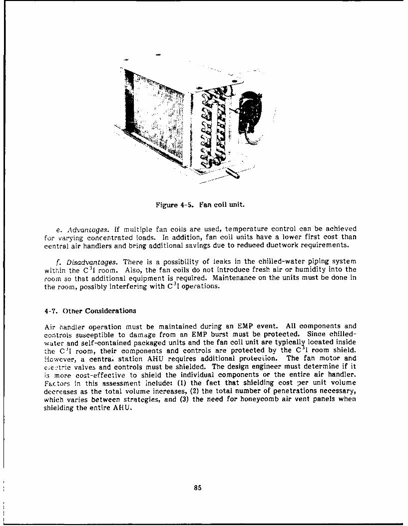
Figure 4-5. Fan coil unit.
e. Advanages. if multiple fan coils are used, temperature control can be achieved
for varying concentrated loads. In addition, fan coil units have a lower first cost than
central air handlers and bring additional savings due to reduced ductwork requirements.
f. Disadvantages. There is a possibility of leaks in the chilled-water piping system
within the C 31 room. Also, the fan coils do not introduce fresh air or humidity into the
room so that additional equipment is required. Maintenance on the units must be done inthe room, possibly interfering with C 3 1 operations.
4-7. Other Considerations
Air handler operation must be maintained during an EMP event. All components andcontrols susceptible to damage from an EMP burst must be protected. Since chilled-water and self-contained packaged units and the fan coil unit are typically located inside
the C31 room, their components and controls are protected by the C I room shield.However, a central station AHU requires additional prouection. The fan motor and
Cietric valves and controls must be shielded. The design engineer must determine if it
is more cost-effective to shield the individual components or the entire air handler.Factors in this assessment include: (1) the fact that shielding cost per unit volumedecreases as the total volume increases, (2) the total number of penetrations necessary,which varies between strategies, and (3) the need for honeycomb air vent panels whenshielding the entire AHU.
85
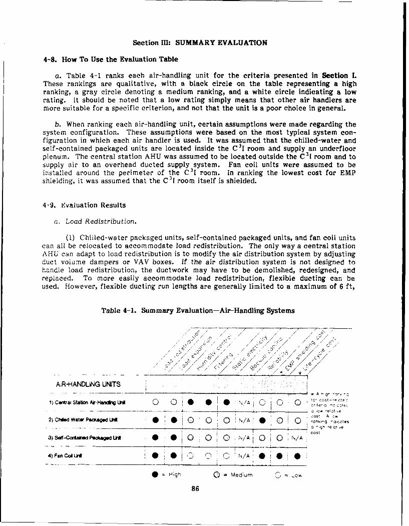
Section Im: SUMMARY EVALUATION
4-8. How To Use the Evaluation Table
a. Table 4-1 ranks each air-handling unit for the criteria presented in Section I.These rankings are qualitative, with a black circle on the table representing a highranking, a gray circle denoting a medium ranking, and a white circle indicating a lowrating. It should be noted that a low rating simply means that other air handlers aremore suitable for a specific criterion, and not that the unit is a poor choice in general.
b. When ranking each air-handling unit, certain assumptions were made regarding thesystem configuration. These assumptions were based on the most typical system con-figuration in which each air handler is used. It was assumed that the chilled-water andself-contained packaged units are located inside the C 31 room and supply an underfloorplenum. The central station AHU was assumed to be located outside the C31 room and tosupply air to an overhead ducted supply system. Fan coil units were assumed to beinstalled around the perimeter of the C 31 room. In ranking the lowest cost for EMPshielding, it was assumed that the C 3 I room itself is shielded.
4-9. Evauation Results
a. Load Redistribution.
(1) Chilled-water packaged units, self-contained packaged units, and fan coil unitscan all be relocated to accommodate load redistribution. The only way a central stationAHU can adapt to load redistribution is to modify the air distribution system by adjustingduct volume dampers or VAV boxes. If the air distribution system is not designed tohandle load redistribution, the ductwork may have to be demolished, redesigned, andreplaced. To more easily accommodate load redistribution, flexible ducting can beused. However, flexible ducting run lengths are generally limited to a maximum of 6 ft,
Table 4-1. Summary Evaluation-Air-Handling Systems
/" // /
~ -~/- c-, ",> / / ' ~ ' / , ' . . .0/ .
AIR-HANDUNG UNITS
1)- __ _ -- station,________________N/A_(D_ ,. s O e cte
cost A c*
2)Chied Water Packagdi W* 0 0 C 0 N/Al 0 0 rankmg
tot
3) SeI-Crtah Packag d 0 0 0 0 N/A 0 0 N/A
4) Fan CoIl 0 ' N/A
* V edium QD
86
due to the relatively high-pressure loss associated with it. Furthermore, flexible ductingis not generally used in high-pressure applications.
(2) If multiple units are used, the chilled-water and self-contained packaged unitsand the fan coil units can be oversized to accommodate load redistribution. When theload concentration is relocated, the unit serving the area of concentrated load will run atnearly full load. The unit serving the area from which the load has been shifted will thenrun at partial load. Oversizing a central station AHU will increase its ability to handleload expansion, but will not improve its ability to handle load redistribution.
(3) For these reasons, a high ranking was given to chilled-water packaged units,self-contained packaged units, and fan coil units. The central station AHU was given amedium ranking due to its lower flexibility.
b. Load Expansion.
(1) All of the air-handling units evaluated can be oversized to accommodate loadexpansion. A well designed chilled-water distribution system within the C 31 room is builtwith extra piping connections and valves to plan for the installation of additional chilled-water packaged units or fan coil units. The additional units will handle load expansiona.-.d can be installed without interrupting operation of the existing units. Similarly, thecondenser piping system can be designed and built to accommodate additional self-con-tained packaged units.
(2) Witn a central station AHU, the fan speed can be increased up to a certainpoint to increase the supply air flow rate, thus accommodating load expansion. Unless avariable- or multiple-speed fan is used, the variable-pitch fan pulleys must be adjustedmanually to increase the fan speed and supply air flow rate. This would require shuttingdown the unit while adjustments are made. However, the fan speed can be increased onlyup to a certain maximum limit. If the maximum speed results in a supply flow rate thatis still inadequate to handle the increased load, the cooling coil must be replaced withone of larger capacity. Again, this modification requires that the unit be shut down.
(3) Due to the factors just discussed, a high ranking was given to the chilled-water packaged units, selt-contained packaged units, and fan coil units. The centralsta:ion AHU received a medium ranking because of the complexities involved with in-creasing its cooling capacity.
c. Precise Control of Humidity.
F) ?an coil units can dehumidify, but not humidify. Therefore, fan coil unitswere given a low ranking under this criterion.
(2) As mentioned in the system description, if multiple packaged units (chilled-water or self-contained) are used, and the controls of the individual units drift out ofcalibration, the units can "fight" each other. Although the dew point control systemdescribed previously could solve this problem, the system uses a central AHU to providehumidity control. Thus, the chilled-water and self-contained packaged units received amedium ranking and the central station AHU was given a high ranking. It should be notedthat, in applications requiring only one chilled-water or self-contained packaged unit,unit "fighting" is not an issue. In these applications, the chilled-water and self-containedpackaged units would receive high rankings.
87
d. Filtering of Particulates.
(1) Central station AHUs are available with automatic, roller-type filtermechanisms. When a differential pressure controller senses that the filter is dirty, newfilter material is rolled into place. Continuous, adequate filtration is achieved withoutrequiring the time and effort of a maintenance engineer. Furthermore, central stationAHUs typically filter both return air and outside air. For this reason, the central stationAHU received a high rating.
(2) While both chilled-water and self-contained packaged units are available withalarms that signal when a filter is dirty, the filters must be changed manually. "hisarrangement increases the chance that the units will operate at least some of the timewith clogged filters. Also, packaged units usually filter only return air. Outside air mustbe filtered by a separate system, such as a central station AHU. Thus, both the chilled-water and self-contained packaged units received a medium ranking.
(3) Fan coil units do not have alarms that indicate when a filter is dirty. Withouta dedicated, comprehensive maintenance program, fan coil units could operate for a longtime with dirty filters, which decreases efficiency. Also, fan coil units filter only returnair. Thus, the fan coil unit was given a low ranking.
e. Static Electricity Control. For AHUs, the control of static electricity is mainly afunction of regulating the relative humidity of the air supplied to the C3I room. Thus,the rankings for static electricity control are the same as those for the humidity controlcriterion. The central station AHU received a high ranking, the chilled-water self-contained packaged unit was ranked medium, and the fan coil unit was given a lowranking.
f. Backup Cooling Capacity. In the event of a power failure, chilled-water airhandlers receive chilled water from the backup cooling system instead of the chiller.Self-contained packaged units are connected to a UPS to provide cooling during a poweroutage. Thus, backup cooling capacity is a function of the chilled water distribution andUPS, and does not apply to air handlers. Therefore, "N/A" appears in the evaluationtable for all AHUs under this criterion.
g. Reliability.
(1) While all of the AHUs are generally reliable, rankings for this criterion werebased on the relative number of components within the air handlers that are subject tofailure. The level of redundancy offered by systems using each type of AHU was alsoconsidered in the ranking process.
(2) Since fan coil units have tne fewest components of any of the units evaluatedand since the use of multiple units provides a certain amount of redundancy, these unitsreceived a high ranking. Chilled-water and self-contained packaged units designed forC31 environments are built with a higher level of reliability than conventional packagedunits for comfort applications. Since multiple packaged units are typically used in C 31rooms, redundancy and reliability are enhanced. Thus, chilled-water packaged unitsreceived a high ranking. Since self-contained packaged units have more components(e.g., compressors) than chilled-water packaged units, they were given a medium ranking.
88
(3) With all of its return, relief, and outside air dampers and actuators, thecentral station AHU has more points of potential failure than the other units. Typically,only one central station AHU serves the C31 room. The number of components and lackof redundancy resulted in a low ranking for central station AHUs.
h. Least Cost for EMP Shielding.
(1) The ranking of least cost for EMP shielding was based, in part, on the relativesize and number of the shielding penetrations associated with the typical configuration ofthe AHU. This ranking was also based on the air handlers' requirements for additionalEMP shielding to ensure operation during an EMP event. The supply and return air ductsof a central station AHU must be sized to handle the total conditioned air flow of theC 31 room, in addition to outside air, for minimum ventilation and positive pressuriz-ation. Assuming the C 3i room itself is EMP-shielded, the central station AHU has thelargest area of EMP penetrations of any other air handler evaluated. Also, centralstation AHUs are normally located remotely from the C 31 room, and therefore outsidethe EMP shield. The central station AHU must be provided with separate shielding,greatly increasing the cost of EMP protection. Thus, the central station AHU received alow ranking.
(2) Chilled-water packaged units have penetrations for chilled water, condensate,and humidifier water supply piping. Self-contained packaged units have condenser,condensate, and humidifier water supply piping penetrating the EMP shield. The size andnumber of EMP shield penetrations are about the same for both types of packaged unit,but less than that for central station AHUs. Since packaged units are typically locatedinside the C3 I room, the units do not require additional shielding. Both chilled-water andself-contained packaged units received medium rankings.
(3) Fan coil units have only chilled-water and condensate piping to penetrate theEMP shield. Furthermore, fan coil units are located inside the C 31 room and do notrequire additional shielding to ensure their operation during an EMP event. Fan coil unitswere given a high ranking.
g. Lowest Life-Cycle Cost.
(1) Life-cycle cost for air-handling units is primarily a function of first cost,energy operating cost, and maintenance cost. Since the fan coil unit is the most basic ofthe air handlers evaluated and has the fewest number of components, it has the lowestfirst cost and maintenance cost of any of the air handlers. Also, the fan coil unit has nohumidifier or reheat coil. Therefore, it has the lowest energy operating cost. Thus, thefan coil unit received a high ranking for lowest life-cycle cost.
(2) Per ton, the central station AHU has a lower first cost than the chilled-waterpackaged unit. Due to the fact that larger motors generally have higher efficienciesthan smaller ones, the fan energy per ton is less for the central station air handler thanfor the chilled-water packaged unit. Furthermore, if the control system is not designedproperly, multiple chilled-water packaged units can compete, contributing to a higherenergy operating cost than with central station AHUs. However, the labor to keep all ofthe return, relief, and outside air dampers in a central AHU adjusted properly produceshigher maintenance costs compared with chilled-water packaged units. All of thesefactors result in relatively equal life-cycle costs. Thus, both the central station AHUand the chilled-water packaged unit received medium rankings.
89

(3) Since self-contained packaged units incorporate refrigeration equipment, theirfirst cost, energy operating cost, and maintenance cost are higher than any of the otherair handlers evaluated and would be very difficult to evaluate on an equal basis with theother AHUs. Thus, the self-contained packaged units are not ranked in the table.
(4) It should be noted that using self-contained packaged units will reduce therequired capacity of the liquid chilling system compared with chilled-water AHUs.However, the COP of a large liquid chilling system is much higher than that of themultiple small compressors used in self-contained packaged units. Furthermore, it isdifficult to compare fan coil units directly to the other air handlers evaluated since theydo not have humidifiers or reheat coils.
90
5 LIQUID CHILLING SYSTEMS
Section I: GENERAL
This chapter evaluates design approaches for liquid chilling systems serving electronicequipment rooms. The following criteria are used to evaluate each system component:
1. Flexibility in meeting load expansion.
2. Capacity to provide 15 min of backup cooling.
3. Reliability.
4. Least cost for EMP shielding.
5. Lowest life-cycle cost.
5-1. Liquid Chiller Types
Only the liquid chilling systems used most often to serve C31 facilities are evaluated.Less common chillers, such as steam turbine units, are not addressed. However, thesteam turbine power plant usually serves the compressors and associated componentscovered in this chapter. The following liquid chilling systems are described:
a. Reciprocating chillers.
b. Rotary screw chillers.
c. Centrifugal chillers.
d. Absorption chillers.
e. Gas engine-driven chillers.
Section 11: SYSTEM DESCRIPTION
5-2. Classes and Components
a. Liquid chilling systems can be divided into two main categories: (1) vapor com-pression and (2) absorption. Vapor compression liquid chilling systems consist of fourbasic components: (1) compressor, (2) condenser, (3) evaporator, and (4) expansiondevice. Vapor compression liquid chilling systems are usually specified by the type ofcompressor used to achieve a refrigeration effect (e.g., centrifugal or reciprocating).Corcpressors are categorized as either positive displacement or turbo-compressors (cen-trifugal).
b. Vapor compression chillers can use a variety of condensing methods. A water-cooled unit uses an evaporative cooling tower. A remote air-cooled condenser unit uses aremote water coil/fan condenser combination to cool water that has picked up heat from
91

the refrigerant vapor. An air-cooled packaged unit uses air blown directly overrefrigerant piping to cool the refrigerant vapor. A water-cooled condenser allows thehighest efficiency operation. It enables heat rejection to a lower temperature (near thewet bulb temperature) than an air-cooled condenser. Also, water is a more efficient heattransfer medium than air.
c. Absorption chillers have the following basic components: (1) generator, (2)absorber, (3) evaporator, (4) condenser, (5) solution heat exchanger, (6) solution andevaporator pumps, and (7) expansion device. Absorption chillers are usually specified interms of both the heat source and generator type (e.g., steam single-stage, gas-firedtwo-stage). In general, absorption chillers are water-cooled, although they are availableas air-cooled in small size ranges.
5-3. Reciprocating Chillers
a. Operation.
Reciprocating chillers use a positive displacement compressor in which refrigerantgas is compressed by a piston that reduces the volume of the refrigerant in a closedcylinder. Packaged reciprocating chillers with cooling capacities over 100 tons typicallynave several compressors in a singie unit. The cooling capacity is generally controlled bya combination of compressor cycling and cylinder unloading in which the suction gas tosome cylinders is shut off. Partial load efficiencies within a few percent of design valuesdown to 20 percent load can be obtained with this control strategy.
(2) A water-cooled reciprocating chiller (Figure 5-1) of 120 tons operating atAmerican Refrigeration Institute (ARI) conditions (85 OF entering condenser water and45 'F exiting chilled water temperature) can achieve COPs of up to 4.07 (0.86kW/ton). When the exiting chilled water temperature is increased to 50 OF, the COP canreach 4.28 (0.82 kW/ton).
Figure 5-1. Water-cooled reciprocating chiller.
92
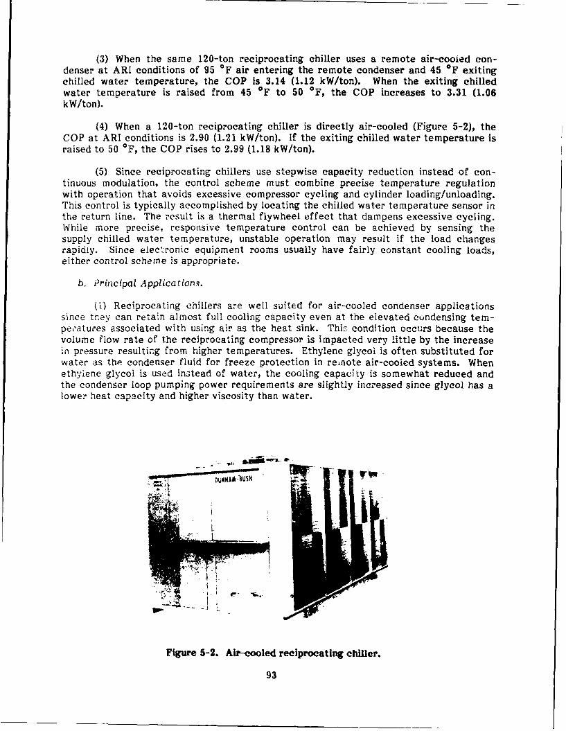
(3) When the same 120-ton reciprocating chiller uses a remote air-cooied con-denser at ARI conditions of 95 OF air entering the remote condenser and 45 OF exitingchilled water temperature, the COP is 3.14 (1.12 kW/ton). When the exiting chilledwater temperature is raised from 45 OF to 50 OF, the COP increases to 3.31 (1.06kW/ton).
(4) When a 120-ton reciprocating chiller is directly air-cooled (Figure 5-2), theCOP at ARI conditions is 2.90 (1.21 kW/ton). If the exiting chilled water temperature israised to 50 OF, the COP rises to 2.99 (1.18 kW/ton).
(5) Since reciprocating chillers use stepwise capacity reduction instead of con-tinuous modulation, the control scheme must combine precise temperature regulationwith operation that avoids excessive compressor cycling and cylinder loading/unloading.This control is typically accomplished by locating the chilled water temperature sensor inthe return line. The result is a thermal flywheel effect that dampens excessive cycling.While more precise, responsive temperature control can be achieved by sensing thesupply chilled water temperature, unstable operation may result if the load changesrapidly. Since electronic equipment rooms usually have fairly constant cooling loads,either control scheme is appropriate.
b. Principal Application.,.
(i) Reciprocating chillers are well suited for air-cooled condenser applicationssince trey can retain almost full cooling capacity even at the elevated condensing tem-pe atures associated with using air as the heat sink. This condition occurs because thevolume flow rate of the reciprocating compressor is impacted very little by the increasein pressure resulting from higher temperatures. Ethylene glycol is often substituted forwater as the condenser fluid for freeze protection in renote air-cooled systems. Whenethylene glycol is used instead of water, the cooling capacity is somewhat reduced andthe condenser loop pumping power requirements are slightly increased since glycol has alower heat capacity and higher viscosity than water.
DLMHA .USH
Figure 5-2. Air-cooled reciprocating chiller.
93
(2) Reciprocating chillers can be used in C3I room applications as the main chillerwhen cooling loads are less than 250 tons, which is the upper limit of available capacity.They can handle small steps of load expansion since they can be installed with variousincremental capacities. When a large central or building chiller serves the C3 I room andother loads during normal office hours, it often needs to operate only at a very light loadat night (other building loads are not present). Reciprocating chillers can be usedefficiently at night to closely match the C 31 room cooling load.
(3) Air-cooled packaged chillers are well suited for retrofit applications becausethey can be located on the roof near the C 3 1 room. In this case, only the chilled-waterpiping needs to be run to the C 31 room and air handler.
c. Sizes. Reciprocating chillers are available with capacities ranging from 2 to 250tons.
d. Cost.
(1) Air-cooled reciprocating chillers range in equipment cost from around$400/ton for capacities over 100 tons to $850/ton for capacities under 10 tons. Chilled-water piping and pumps, controls, and installation result in installed costs of $800 to$1450/ton.
(2) Water-cooled reciprocating chillers range in equipment cost from about$300/ton for capacities over 100 tons to $900/ton for capacities under 10 tons. Coolingtowers, condenser water piping and pumps, controls, and installation result in installedcosts ranging from $725 to $1700/ton.
(3) These costs do not inciude EMP shielding. Estimated costs for shieldingchiller equipment are addressed in paragraph 5-7.
e. Advantages.
(1) Since reciprocating chillers are well suited for air-cooled condensers, they arequite versatile for retrofit applications. In air-cooled packaged configurations, recipro-cating chillers can be easily installed on a rooftop near the location to be served. Evenwhen a remote air-cooled condenser is used, retrofit installations are straightforward,requiring minimal demolition.
(2) Reciprocating chillers are the most compact in volume, on a per-ton basis, ofall chillers evaluated. Besides volume, another important size consideration is theoccupied floor area, often called the "footprint" of the chiller. Below 450 tons, thereciprocating chiller has the smallest footprint of all chillers evaluated. At a capacity of300 tons, the footprint of two 150-ton reciprocating chillers is smaller than the othersingle chiller rated at 300 tons. However, above 450 tons, the footprint of the centri-fugal chiller is smaller than that of the reciprocating chiller.
(3) Reciprocating compressors are also versatile because they can be used to coolair as well as water. By using a DX coil, air can be cooled directly without the need forchilled water and associated piping. One configuration for cooling both the space andequipment of C3I rooms uses self-contained DX air handlers to cool air supplied to anunderfloor plenum, and reciprocating chillers to provide water-cooled electronic equip-ment with chilled water. An interesting feature of the water-chilling portion of thissystem is that it incorporates a water storage tank module that provides 20 min of back-up cooling to the water-cooled electronic equipment in the event of a power failure.
94

f. Disadvantages. The suction and discharge valves associated with the reciprocatingcompressor can cause excessive pressure losses due to either high gas velocities or poormechanical action. These conditions can reduce the COP and also the service life of the
unit. Additional pressure losses can be caused by the suction shutoff valves often used
for capacity control. Air-cooled reciprocating chillers have the lowest COP of allchillers evaluated, except for air-cooled centrifugal chillers. Because of the recipro-cating motion and large number of contacting parts, reciprocating chillers tend to benoisier than other chillers of equal capacity.
5-4. Rotary Screw Chillers
a. Operations.
(1) A helical rotary screw compressor forces the refrigerant vapor through acontinuously decreasing volume between two counter-rotating, multilobed helical rotors
until it is finally discharged under high pressure. Uniform, nonpulsating gas flow can beachieved by using multiple rotors. Figure 5-3 shows a rotary screw chiller and Figure 5-4demonstrates the compression process.
(2) The capacity is contolled by a slide valve that varies the opening of tl~e rotor
housing, effectively varying the compressor displacement. Since the slide valve does notintroduce additional losses, the partial load performance of rotary screw chillers remainshigh down to 10 percent full load. Water-cooled rotary screw chillers can achieve COPs
up to 4.83 (0.73 kW/ton) at 85 "F entering condenser water and 45 OF exiting chilledwater. [f the leaving chilled-water temperature is raised to 50 OF, the COP increases to5.14 (0.68 kW/ton). Rotary screw chillers with remote air-cooled condensers can achieveCOPs up to 3.1 (1.14 kW/ton).
(3) Rotary screw compressors are oil-injected to provide lubrication and cooling,and to seal potential leaks through the clearance between moving parts. In addition tocooling and improving the pumping efficiency, oil injection reduces noise levels. Since
rotary screw chillers are designed for oil injection, they can also handle occasionalslugging of liquid refrigerant without damage to the conpressor.
Figure 5-3. Rotary screw chiller.
95
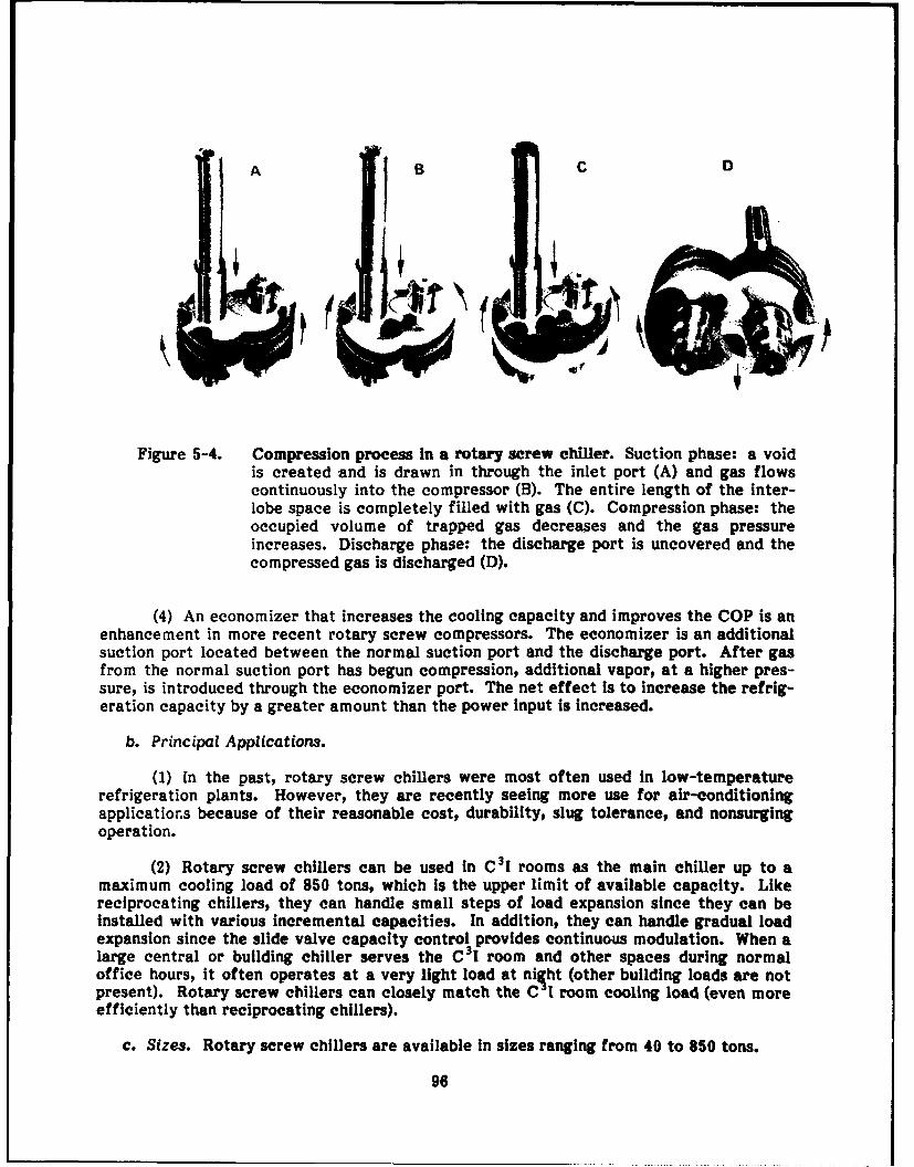
A B C D
Figure 5-4. Compression process In a rotary screw chiller. Suction phase: a voidis created and is drawn in through the inlet port (A) and gas flowscontinuously into the compressor (B). The entire length of the inter-lobe space is completely filled with gas (C). Compression phase: theoccupied volume of trapped gas decreases and the gas pressureincreases. Discharge phase: the discharge port is uncovered and thecompressed gas is discharged (D).
(4) An economizer that increases the cooling capacity and improves the COP is anenhancement in more recent rotary screw compressors. The economizer is an additionalsuction port located between the normal suction port and the discharge port. After gasfrom the normal suction port has begun compression, additional vapor, at a higher pres-sure, is introduced through the economizer port. The net effect is to increase the refrig-eration capacity by a greater amount than the power input is increased.
b. Principal Applications.
(1) In the past, rotary screw chillers were most often used in low-temperaturerefrigeration plants. However, they are recently seeing more use for air-conditioningapplications because of their reasonable cost, durability, slug tolerance, and nonsurgingoperation.
(2) Rotary screw chillers can be used in C31 rooms as the main chiller up to amaximum cooling load of 850 tons, which is the upper limit of available capacity. Likereciprocating chillers, they can handle small steps of load expansion since they can beinstalled with various incremental capacities. In addition, they can handle gradual loadexpansion since the slide valve capacity control provides continuous modulation. When alarge central or building chiller serves the C3 I room and other spaces during normaloffice hours, it often operates at a very light load at ni ht (other building loads are notpresent). Rotary screw chillers can closely match the C1I room cooling load (even moreefficiently than reciprocating chillers).
c. Sizes. Rotary screw chillers are available In sizes ranging from 40 to 850 tons.
96

d. Cost. Equipment costs for rotary screw chillers range from $220 to $360/ton.Cooling towers, condenser water piping and pumps, chilled-water piping and pumps,controls, and installation result in installed costs ranging from $550 to $800/ton. Thesecosts do not include EMP shielding; see paragraph 5-7.
e. Advantages.
(1) Since the slide valve used for capacity control displaces the intake chargebefore compression begins, little or no losses occur. For this reason, there is high partialload performance down to 10 percent of full load. Thus, a rotary screw chiller can beinstalled when gradual future load expansion is anticipated. Before the load is added, therotary screw chiller can act as a backup unit to, say, a centrifugal base chiller. Asincrements of load are added, the rotary screw chiller operates efficiently at low load tosatisfy the additional cooling requirements.
(2) Because rotary screw chiliers are oil-injected, they nave lower dischargetemperatures and run quieter than comparable reciprocating chillers. Rotary screwchillers are generally more compact in volume (per-ton) than centrifugal and absorptionchillers.
f. Disadvantages. Oil injection requires the use of an oil separator to remove oilfrom the high-pressure refrigerant. Also, additional equipment is needed to cool theoil. This equipment requires proper maintenance to ensure trouble-free operation of therotary screw chiller. Although more compact in volume than the centrifugal and absorp-tion chillers, the footprint of a rotary screw chiller is larger than that of a reciprocatingor centrifugal chiller of equal capacity.
5-5. Centrifugal Chillers
a. Operation.
(1) Centrifugal chillers (Figure 5-5) use a compressor that increases the pressureof the refrigerant vapor by raising its speed in a high-speed, rotating impeller and thenpassing the vapor through a diffuser. Single- or multistage compressors can be used, withmultistage compressors providing improved performance and smoother operation at lightloads. The capacity of centrifugal chillers is generally controlled by inlet guide vanesthat prerotate the refrigerant vapor before it reaches the impeller. This action lowersthe amount of momentum that can be transferred to the vapor by the rotating impeller,and thus reduces the increase in pressure.
(2) The partial load performance of centrifugal chillers is very good from 40 to100 percent load. However, below 40 percent load, the performance declines dramati-cally. The ability to continuously modulate capacity with nearly proportionate changesin input power enables the centrifugal chiller to provide precise temperature control withenergy efficiency. COPs of up to 5.74 (0.61 kW/ton) are obtainable from water-cooledcentrifugal chillers. With 85 OF entering condenser water and 44 OF exiting chilledwater, the COP of a 450-ton water-cooled centrifual chiller is 5.57 (0.63 kW/ton). Ifthe exiting chilled water temperature is raised to 46 F, the COP increases to 5.62.
97

FRONT VIEW
1 - Flow Valve Chamber2 - Cooler Charging Valve3 Refrigerant Level Sight Glasses4 - Field Wiring Knockouts5 - Machine Informative Plate Location6 - Oil Reservoir Temperature Gage7 - Oil Heater and Thermostat Terminal Box
s 8 - Oil Level Sight Glass9 - Return-Oil Temperature Gage (Hidden)
10 - Compressor Nameplate (Hidden)11 - Bellows Seal (Hidden)
" ,12 - Diffuser Feedback Potentiometer (Hidden)13 - Vane Seal Oiler14 - Microprocessor Control Panel
19 15 - Condenser Pressure Gage16 - Cooler Pressure Gage17 - Oil Pump Differential Pressure Gage
20 t16 - Condenser Water Nozzles19 - Safety Relief Device (Rupture Disc)20 - Chilled Water Temperature Sensor
S5 21 - Cooler Water Nozzles22 - Support Plates23 - Condenser Refrigerant Temperature Sensor
REAR VIEW
24 - Cooler Refrigerant Temperature Sensor25 - Purge Assembly
33 26 - Discharge Temperature Sensor (Hidden)27 - Diffuser Solenoid Valves (Hidden)28 - Guide Vane Actuator29 - Compressor Access Plate30 - Inlet Volute Drain Strainer31 - Compressor Terminal Box32 - Motor End Cover
2 33 - Motor Rotation Sight Glass34 - Refrigerant Filter35 - Oil Cooler Solenoid Valve and Plug Valve36 - Oil Pump, Cooler and Filter Assembly
35 37 - Oil Cooler Drain Plug36 - Oil Charging Valve39 - Oil Pressure Regulating Valve (Factory Set)
-36 40 - Oil Pump Starter. Factory Installed
Figure 5-5. CentrIfugal chiller. (Source: Carrier Product Catalog, 1988. Usedwith permission.)
98
b. Principal Applications.
(1) Since centrifugal chillers are typically used in the larger capacities (over 250tons), they are usually water-cooled by a flooded, shell-and-tube condenser connected toan evaporative cooling tower. Air-cooled condensers can be used with chillers that usehigher pressure refrigerants, but with a substantial energy penalty. Since, ton-for-ton,centrifugal compressors have a higher volumetric flow than positive displacement com-pressors, air cooling is not as effective for centrifugal chillers as it is for positive dis-placement chillers. The performance penalty associated with air-cooling a centrifugalchiller is as follows:
Water-Cooled RemoteEvaporative Air-CooledCooling Tower CondenserCOP COP
150-Ton reciprocating chiller 4.13 3.58150-Ton centrifugal chiller 4.43 2.52
(2) Since centrifugal chillers have the highest COP of all chillers evaluated, theycan be used effectively as the main chiller in C3i room applications. Above 40 percentload, their partial load performance is excellent. Thus, a centrifugal chiller can beinstalled when gradual future load expansion is anticipated. Before the load is added, thechiller will act as a backup unit to the base chiller. As load is gradually added, thecentrifugal chiller will operate efficiently at partial load to satisfy the additional coolingrequirements.
c. Sizes. Packaged centrifugal chillers are available in sizes ranging from about 80to 2400 tons. Within the ranges of 200 to 400 tons and 400 to 600 tons, the requiredcooling capacity can be matched very closely by mixing and matching different com-pressors, motors, and condensers. Field-erected units can achieve capacities of up to10,000 tons.
d. Cost.
(1) Depending on cooling capacity, centrifugal chillers range in equipment costfrom $130 to $280/ton. Cooling towers, condenser water piping and pumps, chilled-waterpiping and pumps, controls, and installation result in installed costs ranging from $450 to$700/ton.
(2) These costs do not include EMP shielding; see paragraph 5-7.
e. Advantages.
(1) Water-cooled centrifugal chillers larger than 400 tons can achieve a COP of upto 5.74 (0.61 kW/ton)--the highest COP of any other chiller evaluated. The partial loadperformance of centrifugal chillers is very good from 40 to 100 percent load. The abilityto continuously modulate capacity with nearly proportionate changes in input powerallows the centrifugal chiller to combine precise temperature control and high-energyefficiency.
99

(2) For a given capacity, centrifugal compressors have a greater volumetric flowof refrigerant vapor than positive displacement compressors. For adequate compression,a centrifugal compressor must spin faster than positive displacement compressors.However, minimal vibration or wear results from the higher speed because of the steadi-ness of motion and the absence of contacting parts.
(3) For chillers of equal capacity, the volume of centrifugal chillers is larger thanreciprocating and rotary screw chillers and smaller than absorption chillers. Whileranking third among the evaluated chillers in volume, centrifugal chillers rank muchbetter on the basis of footprint size. Below 450 tons, the footprint of the centrifugalchiller is smaller than that of the rotary screw and absorption chillers. Above 450 tons,the footprint of the centrifugal chiller is smaller in area than that of any other chillerevaluated.
f. Disadvantages. Partial load performance is limited to around 40 percent of fullload. At partial loads below 40 percent, unstable operation called "surging" occurs.When a centrifugal chiller surges, refrigerant travels back and forth through the unit,causing considerable vibration, noise, and heat. If allowed to operate in a surging condi-tion for an extended duration, the centrifugal compressor will become damaged.
5-6. Absorption Chillers
a. Operation.
(1) Absorption chillers are similar to vapor compression chillers in that bothevaporate and condense refrigerant at two different pressures. However, instead of acompressor, absorption chillers use steam- or gas-fired generators to produce a pressuredifferential. While vapor compression chillers rely on an expansion valve alone to createlow pressure, absorption chillers use a combination of an expansion valve and the strongaffinity of an absorbent for the refrigerant to achieve this result.
(2) The most common absorbent/refrigerant combination is lithium bromide/water, with water acting as refrigerant. However, chillers in the 3- to 5-ton capacityrange sometimes use an ammonia/water combination, with ammonia as refrigerant.
(3) Figure 5-6 shows a simple lithium bromide/water absorption chiller. Sincethe refrigerant vapor in this system is generated in one step, the machine is referred toas a single-stage, or single-effect, absorption chiller. Operation of the single-stageabsorption chiller consists of the following steps:
(a) Refrigerant vapor from the evaporator is absorbed in the absorber by aconcentrated solution with a strong affinity for the refrigerant.
(b) As the solution absorbs more refrigerant, it becomes weaker in itsaffinity for the refrigerant. The weak solution is pumped to the generator where heat isadded to boil off the refrigerant and, thus, regenerate the weak solution into strongsolution. The strong solution then flows back to the absorber.
(c) A heat exchanger is used to recover heat from the strong solutionreturning to the absorber, preheating the weak solution before it enters the generator.
100
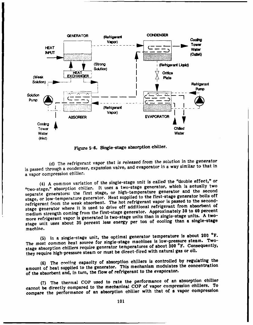
GENERATOR (Refrigerant COENSER
(outlet)lE T HEAT J we
(Strong I(Refrigerant Llcid
HWeEATI Solution) I Orfice(Weaj Plate
Solution) IRefrigerant
___________Purnp
Solution Fa -_1 - --
_____ (Refrigerant
ASORBE EVAPORATOR
Tower -N 1d
Water Water(i let)
Figure 5-6. Single-stage absorption chiller.
(d) The refrigerant vapor that is released from the solution in the generator
is passed through a condenser, expansion valve, and evaporator in a way similar to that in
a vapor compression chiller.
(4) A common variation of the single-stage unit is called the "double effect," or
"two-stage," absorption chiller. It uses a two-stage generator, which is actually two
separate generators: the first stage, or high-temperature generator and the second
stage, or low-temperature generator. Heat supplied to the first-stage generator boils off
refrigerant from the weak absorbent. The hot refrigerant vapor is passed to the second-
stage generator where it is used to drive off additional refrigerant from absorbent of
medium strength coming from the first-stage generator. Approximately 30 to 40 percent
more refrigerant vapor is generated in two-stage units than in single-stage units. A two-
stage unit uses about 35 percent less energy per ton of cooling than a single-stage
machine.
(5) In a single-stage unit, the optimal generator temperature is about 200 *F.
The most common heat source for single-stage machines is low-pressure steam. Two-
stage absorption chillers require generator temperatures of about 300 OF. Consequently,
they require high-pressure steam or must be direct-fired with natural gas or oil.
(6) The enoling capacity of absorption chillers is controlled by regulating the
amount of heat supplied to the generator. This mechanism modulates the concentration
of the absorbent and, in turn, the flow of refrigerant to the evaporator.
(7) The thermal COP used to rate the performance of an absorption chiller
cannot be directly compared to the mechanical COP of vapor compression chillers. To
compare the performance of an absorption chiller with that of a vapor compression
101
chiller, the COP of the vapor compression chiller must be modified to include theefficiency of the electricity-generating plant and distribution system. For example, ifthe efficiency of the generating plant and distribution system is 33 percent, then thecomparable COP of a vapor compression chiller with a mechanical COP of 5.0 is 1.65 (5.0x 33 percent). Single-effect absorption chillers have thermal COPs averaging between0.5 and 0.7, whereas two-stage absorption chillers can have thermal COPs of up to 1.06.
b. Principal Applications.
(1) Lithium bromide/water units are used more for large commercial cooling loadsand ammonia/water units tend to be used more for residential or small commercialapplications. However, ammonia/water absorption chillers have been used for largeindustrial process cooling applications requiring low temperatures.
(2) Lithium bromide/water absorption chillers are typically water-cooled byevaporative cooling towers whereas ammonia/water units are usually air-cooled. Water-cooled, lithium bromide/water absorption chillers may be either direct-fired, usingnatural gas or fuel oil, or indirectly fired, using steam, hot water, or waste heat. Smallair-cooled, ammonia/water absorption chillers are typically available only with directfiring.
(3) Direct-fired, lithium bromide/water absorption chillers are two-stage units.Direct-fired systems can provide both heating and cooling by passing hot refrigerantvapor from the generator to a hot-water heat exchanger. Indirect-fired units can beeither single- or double-effect and are particularly advantageous when adequatequantities of waste heat are available.
(4) Other factors that must be addressed when comparing an absorption chillerwith an electrical chiller include the ability to install a chimney, gas service pipingrequirements (direct-fired only), and available electrical service (new chillers). Further-more, the absorption chiller can also be used for heating.
c. Sizes. Direct-fired, lithium bromide/water, double-effect units are available insizes ranging from 7.5 to 1500 tons. Indirect-fired, lithium bromide/water units areavailable in the single-effect configuration at sizes from 1.3 to 1660 tons and in the two-stage design at sizes from 100 to 1500 tons. Gas-fired, ammonia/water, air-cooled unitsare sized from 3 to 5 tons, or as combination packages from 8 to 25 tons.
d. Cost.
(1) Steam single-stage absorption chillers in the 100-ton range cost from $300 to$500/ton for equipment only. Installed costs in this range are between $730 and$1100/ton. Over 500 tons, the material costs fall to between $230 and $300/ton andinstalled costs run from $480 to $620.
(2) For steam double-effect absorption chillers, the equipment costs in the 100-ton range are between $540 and $900/ton. Over 500 tons, double-effect chillers haveequipment costs ranging from $380 to $440/ton. Double-effect chillers in this range haveinstalled costs that vary from $780 to $840/ton. Installed costs include condenser andchilled water-piping and pumps, cooling towers, controls, and installation. The costs ofEMP shielding are not included; these costs are addressed in paragraph 5-7 below.
102

e. Advantages.
(1) Gas-fired absorption chillers have low electrical power requirements. Forapplications where electricity demand charges are high and gas prices are low, theoperating cost of absorption chillers can be lower than that of electric vapor compressionchillers.
(2) In cogeneration configurations, hot exhaust gases can be used as the heatsource for indirect-fired systems. Other forms of waste heat, such as incinerator heatrecovery, can also be used in indirect-fired systems.
(3) Gas-fired absorption chillers can also supply heat, eliminating the need for aseparate boiler. In general, absorption chillers provide quiet, vibration-free, reliableoperation.
f. Disadvantages.
(1) The major disadvantage of absorption chillers is their high first cost comparedwith electric chillers. In addition, both single- and double-effect absorption chillersrequire cooling towers with about 60 percent more cooling capacity than do vapor com-pression units of equal size due to the extra cooling requirement of the absorber. Thecondenser water piping and pumps must be correspondingly larger than those for anelectric chiller of equal capacity. In facilities not using a gas boiler for heating, theehimney and flue piping required by an absorption unit is an additional cost comparedwith electric units.
(2) In general, absorption chillers have larger space requirements than electricchillers of equal capacity. Response times are also longer than for electric chillers.
5-7. Other Considerations
a. Gas Engine-Driven Chillers. In addition to the chillers evaluated, other types ofchillers used in the past and currently being redeveloped are used in certain appli-cations. One of these is the gas engine-driven chiller. In large applications, the chillersare field-assembled using commercially available component& Large diesel engines aretypically used to drive the compressor. Packaged units in the 150- to 450-ton range thatuse automotive gasoline engines are currently under development. For a complete evalu-ation in this report, the gas engine-driven chiller is described. However, since the pack-aged chillers in the capacities applicable to this report (i.e., 100 to 600 ton) are stillunder development, their reliability has not been proven adequately. Therefore, the gasengine-driven chiller was not ranked In the evaluation process.
(1) Operation.
(a) Figure 5-7 is a simplified schematic of a typical gas engine-driven chillersystem. Gas engine chiller systems couple the shaft output from a gas-powered engine tothe compressor of an open-drive mechanical chiller. Coupling is usually done through anintermediate gearbox in order to match the optimal speeds of the engine and compressor.
(b) Many different options are possible, depending on the size and appli-cation. In small sizes, the engine could be a conventional reciprocating internal com-bustion engine (IC), rotary engine, or a Stirling cycle engine. The compressor driven bythese engines could be the reciprocating or rotary design. For larger units, the IC engine
103
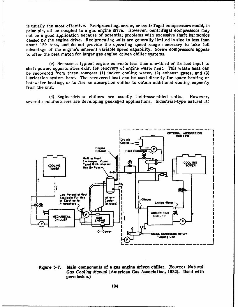
is usually the most effective. Reciprocating, screw, or centrifugal compressors could, inprinciple, all be coupled to a gas engine drive. However, centrifugal compressors maynot be a good application because of potential problems with excessive shaft harmonicscaused by the engine drive. Reciprocating units are generally limited in size to less thanabout 120 tons, and do not provide the operating speed range necessary to take fulladvantage of the engine's inherent variable speed capability. Screw compressors appearto offer the best match for larger gas engine-driven chiller systems.
(c) Because a typical engine converts less than one-third of its fuel input toshaft power, opportunities exist for recovery of engine waste heat. This waste heat canbe recovered from three sources: (1) jacket cooling water, (2) exhaust gases, and (3)lubrication system heat. The recovered heat can be used directly for space heating orhot-water heating, or to fire an absorption chiller to obtain additional cooling capacityfrom the unit.
(d) Engine-driven chillers are usually field-assembled units. However,several manufacturers are developing packaged applications. Industrial-type natural IC
r OPTIONAL ABSORPTION
I "- CHILLERJ Dry Air I
Cooler
Engine -
Exhaust - Hoot Exch r
Mufflfor Heat NExchanger (Vapor COOLING
Type) With internl I TOWERTOWER a. By Page-
* -®
Low Potential HeatAvailable For Use. Atfter- Seor Ejection to CoolerAtimosphere ( itUe) Chilled a
MEHNIA t CHILLERCHILLER EGN
Oil Cooler Steam Cooderote ReturnPumpoing Unit
Figure 5-7. Main components of a gas engine-driven chiller. (Source: NaturalGas Cooling Manual [American Gas Association, 1982]. Used withpermission.)
104

engines are available from several manufacturers with efficiencies of 20 to 32 percent(shaft power to fuel input), based on the higher heating value of natural gas.
(e) Gas engines can be categorized as naturally aspirated or turbocharged.Turbocharging increases the power production and, to a lesser extent, the efficiency ofgas IC engines, by compressing combustion air and therefore allowing a greater amountof fuel to be burned in each cylinder. For example, a 100-kW naturally aspirated enginewith an efficiency of 29.9 percent will produce 150 kW at 30.8 percent efficiency whenturbocharged. Current open-drive screw chillers have COPs of 4.7 to 5.2 (0.9 to 1.0HP/ton). Field-assembled chillers, using standard compressors and heat exchangers, canbe constructed with COPs as high as 5.2 (0.9 HP/ton).
(f) With these engine and chiller efficiencies, systems can be assembled withoverall COPs of up to 1.7. When coupled with a single-stage absorption chiller utilizingthe engine waste heat at a COP of 0.7, the COP can increase up to 2.0. A current pack-age under development at the Gas Research Institute (GRI) has achieved COPs of 1.50without absorption and 1.9 with absorption. Partial load performance of engine-drivenchillers is generally very good because of the ability to operate at variable speeds.
(2) Principal pplications.
(a) Any facility with a central chilled-water plant is a candidate for a gasengine-driven chiller. However, these units are typically found in applications where thewaste neat can be used for hot water or space heating.
(b) It is feasible for a gas engine-driven chiller to serve as standby to anelectric-driven chiller, providing backup cooling in the event of an electrical powerfailure. However, the liquid chilling needs of a C31 facility require an uninterrupted flowof chilled water. The gas engine-driven chiller would take several minutes to bringonline and provide useful cooling. The backup cooling requirements of a C31 facilitywould be better served by the storage system described in Chapter 3.
(3) Sizes. Individual off-the-shelf components can be combined in a wide range ofsizes, from 20 tons up to 700 tons or possibly higher. Reciprocating compressors are themost appropriate for the lower end of this range (iess than 100 tons), whereas screwcompressors are better suited for the larger sizes.
(4) Cost. Industrial-type gas engines cost between $100 and $150/HP for theengine alone. With accessories, unit costs run from $180 to $250/HP. Open-drive chillercosts range from about $200 to $300/ton. Installed costs of engine/chiller combinationsrange from $500 to $650/ton. Cooling towers, condenser water piping and pumps,chilled-water piping and pumps, controls, and installation result in total installed costsranging from $830 to $1100/ton.
(5) Advantages/Disadvantages. The main advantages of engine-driven systemsare the potential for high thermal overall COPs (relative to direct-fired absorptionsystems) and subsequently lower operating costs, and the variable speed capability thatwill improve partial load performance. The disadvantages of these systems are po-tentially poor engine reliability and maintenance problems, noise, the lack of currentlyavailable packaged systems, and the high first cost of current systems, particularly thosewith an absorption chiller heat recovery feature.
105

b. EMP Shielding.
(1) EMP shielding of liquid chilling systems is typically achieved by surroundingthe equipment and controls with a conductive barrier that is grounded separately todissipate EMP voltages and currents. Piping penetrations in the shield are treated bywelding the pipe circumferentially to the shield (see Chapter 4). Electrical penetrationsare treated with various methods using filters and surge-limiting devices. There aremany sources describing EMP hardening techniques and design, as listed earlier. MIL-HDBK-419 provides standardized information on EMP hardening of electronic equipmentfor DOD.
(2) It is very difficult to estimate EMP shielding costs. No single design is suit-able to the majority of applications. In addition, EMP shielding costs per unit volumevary widely, depending on the shield volume. Hardening an entire mechanical room could
cost between $5 and $10/cu ft. However, protecting one small electric motor could costbetween $100 and $200/cu ft. Providing an EMP shield around a 200-ton chiller couldcost between $15 and $25/cu ft. Becaus! of the ventilation requirements, shielding costsfor an air-cooled condenser of similar size could increase to a range between $30 and$50/cu ft. It should be noted that these cost estimates are based on rough generic de-signs and that actual costs may vary significantly.
Section Il: SUMMARY EVALUATION
5-8. How To Use the Evaluation Table
a. Table 5-1 ranks each liquid chilling system for the criteria presented in Section 1.These rankings are qualitative, with a black circle in the table representing a highranking, a gray circle denoting a medium ranking, and a white circle indicating a lowrating. It should be noted again that a low rating simply means other systems are more
suitable for a specific criterion, and not necessarily that the system is a poor choice ingeneral.
b. When ranking each system, certain assumptions were made regarding the systemconfiguration. For example, when considering life-cycle cost, it was assumed that allsystems are served by an evaporative cooling tower in order to evaluate the differentliquid chilling systems on an equal basis.
5-9. Evaluation Results
a. Load Expansion.
(1) When load expansion is the primary consideration, the rotary screw and centri-
fugal chillers have the best ranking. These liquid chilling systems can continuouslymodulate capacity in response to cooling load without excessive cycling or on/off oper-ation. Therefore, both the rotary screw and centrifugal chillers can adapt smoothly togradual load expansion.
106

Table 5-1
Summary Evaluation: Liquid Chilling Systems
'P
1) Reciprocatig Chiers {_0 0 0 A1 0 Ahigh ranking..... -j--.. for cost-related
I ___ criteria indicaoes2) Rotary Screw Cli.., a I £ V a low relative. .. . .cost. A low
ranking indicates
3) Centrifugai Chiers * * a high relative. ... .cost.
4) Absorption t•eS 0 0 0 0
•. 0 0 Mod= Low
(2) When significant steps of load are added to the C 31 room, the availability ofchillers with a variety of incremental steps of capacity becomes a consideration. Bothreciprocating and rotary screw chillers are available with small incremental steps ofcapacity. However, since a more gradual load expansion would cause the reciprocatingchiller to experience a certain amount of cylinder loading and unloading, it was given amedium ranking. Absorption chillers received a low rating primarily because their largersize per ton of cooling limits the amount of capacity that can be added within the mech-anical room.
(3) The partial load performance of a chiller at very low load can have an impacton the ability to handle load expansion. For example, to plan for future load expansion,more capacity than is needed at present can be installed. When the load increases, achiller with good partial load performance can operate satisfactorily until more load isadded so that the extra capacity is used at full load. The reciprocating and rotary screwchillers have good partial load performance at low loads.
b. Backup Cooling Capactty. The capacity of cooling systems to provide 15 min ofbackup cooling in the event of a power failure was discussed in detail in Chapter 2. Allchillers evaluated are capable of providing chilled water at temperatures adequate tosatisfy the cooling requirement, of C3I room space and equipment. All are capable ofsupplying the backup cooling system described in Chapter 3. For this reason, all chillersevaluated received a high ranking for this criterion.
c. Reliability.
(1) All chillers evaluated are generally reliable. For vapor compression chillers,relative reliability is primarily a function of the compressor. The use of an air-cooledcondenser will result in increased gas discharge temperatures, which, in turn, will reducethe equipment service life. On the other hand, air-cooled condensers generally requireless maintenance than cooling towers. However, to compare the chillers on an equalbasis under this criterion, it was assumed that all units are served by an evaporativecooling tower.
107

(2) The steadiness of motion and minimum number of contacting parts in a centri-fugal compressor result in little wear and vibration. The 1987 ASHRAE HVAC Systemsand Applications Handbook lists an expected service life of 23 years for centrifugalchillers. Thus, centrifugal chillers received a high rating for reliability.
(3) Rotary screw chillers have been typically used in low-temperature industrialprocess cooling applications that require rugged, durable equipment. In air-conditioningapplications, they show the same high reliability. Rotary screw compressors use an oilinjection system to lubricate, cool, and seal. Since the rotary screw compressor isdesigned to handle oil, it can also tolerate liquid refrigerant slugging without damage.Therefore, the rotary screw chiller received a high rating.
(4) The reciprocating chiller, though generally reliable, has the most contactingcomponents of any of the chillers evaluated. The suction and discharge valves are thecomponents with the greatest potential for failure. Even though the 1987 ASHRAEHVAC Systems and Applications Handbook shows an expected service life of 20 years,this is less than the 23 years listed for centrifugal and absorption chillers. Therefore, thereciprocating chiller was given a medium rating.
(5) ASHRAE estimates the service life of an absorption chiller at 23 years.Absorption chillers have strict requirements for keeping all internal surfaces clean andall vacuum vessels airtight for the life of the equipment. Failure to prevent the accumu-lation of air and other noncondensable gases can allow salt to crystallize inside the unit.Crystallization renders the chiller inoperable and can corrode internal components overtime. While crystallization is not a problem in new, well maintained absorption chillers,the service life and trouble-free operation depend on the success of efforts to keep theunit clean and airtight. Thus, while the estimated service life of 23 years equals that ofthe centrifugal chiller, more exacting maintenance procedures are required to keep theabsorption chiller operational. For this reason, the absorption chiller was given amedium ranking.
d. Least Cost for EMP Shielding.
(1) If a chiller serves an area that is EMP-protected, then the chiller and relatedequipment must also be provided with EMP protection. If the entire mechanical room isshielded, the overall size of the cooling equipment (and, therefore, the size of the mech-anical room) will impact the cost of EMP protection. If only the electric motors andcontrols are protected, the size and number of the motors and controls dictate the costof EMP shielding. For a particular piping configuration, the cost to protect the integrityof the C 31 room EMP shield from piping penetrations is the same for each of the chillersevaluated, since the same flow of chilled water and, therefore, the pipe size are thesame for each chiller.
(2) In cases for which the entire mechanical room is EMP-shielded, the chillersare ranked according to increasing total volume since larger chillers would require cor-respondingly larger mechanical rooms and, therefore, would carry higher costs for EMPshielding. It should be noted that chiller package footprints and volumes for some typesof chillers vary among manufacturers. This evaluation is based on a review of specificchiller packages and is a generalization.
(3) In cases for which only the electric motors and controls are EMP-shielded, thevapor compression chillers are ranked equally since their compressor, chilled-waterpump, and condenser water pump motors and controls are approximately the same sizefor a given capacity. While electric motor requirements of an absorption chiller are
108

small, two pump motors (the solution and evaporator pumps) must be EMP-shieldedcompared with the one large compressor motor for the vapor compression chillers. Thedifference in cost between EMP shielding two small motors and that to shield one largemotor is not great. The labor cost of protecting two motors offsets the reduced materialcost of the smaller shields.
(4) Another factor is that absorption chillers require a cooling tower that isapproximately 60 percent larger in capacity than a vapor compression chiller of equalsize. Therefore, the related condenser water pumps, motors, and piping are larger for anabsorption chiller. In conclusion, when only the electric motors are EMP-shielded, itcosts more to protect an absorption chiller than to protect a vapor compression chiller.
(5) Since it is more typical to EMP-shield the entire mechanical room than toprotect just the electric motors and controls, the rankings are based on chiller volumeand footprint area. The reciprocating, rotary screw, and centrifugal chillers received ahigh ranking, and the absorption chiller was ranked low. A ranking of high in the leastcost for EMP shielding criterion indicates a relatively low cost. Conversely, a low ratingdenotes a relatively high cost for EMP shielding.
e. Lowest Life-Cycle Cost.
(1) Components of the total life-cycle cost of a liquid chilling system include thepresent value of: the energy operating costs over the economic life of the equipment;the investment costs of the equipment design, purchase, and installation; the annuallyrecurring (nonfuel) operating and maintenance (O&M) costs; the nonannually recurring(nonfuel) O&M costs; the replacement costs; and the salvage value. A life-cycle costanalysis was conducted for chiller capacities of 100, 200, 400, and 600 tons. Based onthis analysis, the centrifugal chiller has the lowest life-cycle cost for all capacity sizesexcept 100 tons and, therefore, was given a high ranking. In the 100-ton capacity, thecentrifugal chiller was less than 1 percent higher in total life-cycle cost than the rotarychiller, which had the lowest cost in this size category. Though first cost is lower for thecentrifugal chiller in the higher capacity ranges, the primary reason for the high rankingof the centrifugal chiller was its high COP and associated low energy operating costs.
(2) The rotary screw chiller had the next lowest life-cycle cost and received ahigh ranking. As mentioned, in the 100-ton size, the rotary screw chiller had the lowestlife-cycle cost. In the other sizes, the rotary screw chiller was second to the centrifugalchiller in lowest life-cycle cost. Again, energy operating costs had the most impact onthe life-cycle cost and the COP of the rotary screw chiller was second only to the centri-fugal chiller.
(3) The reciprocating chiller had relatively high energy operating costs and, inturn, high life-cycle costs. In the 400- and 600-ton analyses, multiple reciprocatingchillers, each rated at 200 tons, had to be used because reciprocating chillers are notavailable in sizes above 250 tons. Thus, the reciprocating chiller received a mediumranking. The absorption chiller had the highest energy operating costs and, therefore,the highest life-cycle cost of any of the chillers evaluated. The absorption chiller wasgiven a low rating for this reason.
(4) The energy prices and electrical demand charges used In the life-cycle costanalysis are national averages. Local fuel prices and electrical demand charges can havedramatic impacts on the results of the analysis. For example, if the local electricaldemand charges are high and the natural gas prices are low, the absorption chiller mayhave lower energy operating costs than some of the vapor compression chillers. Also, If
109
low-cost waste heat is available, the energy operating cost of the absorption chillerwould De reduced greatly.
(5) The chiller and chilled-water distribution system configuration can impact thelife-cycle cost of liquid chilling systems. For example, certain electronic equipmentrequires direct water cooling. The temperature of chilled water required varies betweenequipment and between models. Typical ranges are from 50 to 70 OF. If a chiller isdedicated to serving water-cooled electronic equipment, the chilled water temperaturesetpoint can be raised above the standard setpoint of 45 OF. Raising the chilled watertemperature setpoint improves the COP, reduces the present value of the energy costs,and reduces the life-cycle cost.
(6) Another example in which the chilled water temperature setpoint can beraised is a case in which air handlers within the C3I room provide sensible cooling only.Humidification and dehumidification are controlled by a central system served by thebuilding chiller. Occupant areas in the C 31 room are also served by an air handler thatreceives chilled water from the building chiller. A dedicated chiller serves water-cooledelectronic equipment and the air handlers that provide sensible cooling only. The elec-tronic equipment and air handler loads can be satisfied with 50 OF chilled water. TheCOP of the dedicated chiller is improved by raising the chilled water setpoint, and thetotal life-cycle cost is reduced.
(7) The installation of multiple chillers in C 31 rooms for redundancy and backuphas significant impacts on partial load performance and life-cycle costs. Frequently,three chillers, each capable of handling more than the total cooling load, are installed ina C31 facility. This is sometimes referred to as the "N+2 rule" as described earlier.Normally, two of the chillers are run at partial load to satisfy the cooling requirements.The third chiller is used as a backup. If one of the two operating chillers fails, the othercan handle the whole load, while the third chiller still provides the required redundancy.Since ta.o chillers are normally running at less than full load, the partial load per-formance of the selected chillers dictates the energy operating costs and, therefore, thelife-cycle costs.
110
6 CONCLUSION
6-1. Four types of cooling systems have been evaluated in terms of different per-formance criteria to present guidance for C 31 facility designers. The four types ofsystems were: air distribution, chilled-liquid distribution, air-handling, and liquid chillingsystems. Performance criteria included flexibility in meeting load redistribution andload expansion requirements, humidity control, particulate matter filtering ability, staticelectricity control, backup cooling, reliability, lowest cost for EMP shielding, and lowestlife-cycle cost. Advantages and disadvantages of each type of unit have beenpresented. Relative costs have been estimated to allow comparisons.
6-2. The information in this report is not intended to replace the design analysis. Thegoal was to provide designers with a comprehensive assessment of the systems and com-ponents available and their predicted performance under a variety of conditions. Coolingsystems must be designed on a case-by-case basis, with the designer considering factorssuch as cost, location, and mission criticality of the C31 facility.
METRIC CONVERSION TABLE
in. 2.54 cm
I ft = 0.305 m
I sq ft = 0.092 m2
1 Cu ft = 0.028 m3
1 lb = 0.453 kg
1 ton 907.2 kg
1 gal 3.785 L
I psig 6.895 kPa
1 HP = 0.75 kW
F = (C C x 1.8) + 32
111

BIBLIOGRAPHY
American Society of Heating, Refrigerating, and Air-Conditioning Engineers (ASHRAE)Handbook (1987), Chapters 2, 32, 33.
Carnes Company, Inc., Product Catalogs CG-9G, R-80E, D-22D, D-21E, D-90B, TW-92H,R-71F (1987).
Connor, M. C., and L. Hannauer, "Computer Center Design," ASHRAE Journal (April1988).
EMI Shielding Products Catalog (Tecknit EMI Shielding Products, 1980).
EMP Engineering Handbook for Ground Based Facilities - Vol II: Design and Engineering(Defense Nuclear Agency [DNA], 1986).
Mclnerney, M., et al., The Effect of Fluids on Waveguides Below Cutoff Penetrations asRelated to Electromagnetic Shielding Effectiveness, Technical Report M-354/ADA144685 (U.S. Army Construction Engineering Research Laboratory[USACERL], July 1984).
Means Mechanical Cost Data, Division Number 15 (R.S. Means Company, Inc., 1987).
Military Handbook (MIL-HDBK-253), Guidance for the Design and Test of SystemsProtected Against the Effects of Electromagnetic Energy (Department of Defense[DOD], 1978).
MIL-HDBK-419, Grounding, Bonding and Shielding for Electronic Equipments andFacilities (DOD, 1986).
Natural Gas Cooling Manual (American Gas Association, 1982).
Product AC-IOIB/STEP1 (Buffalo Forge Co., 1983).
Product Bulletins 3002, 3003, 2500W, 3004, 3005, 2500A, 3021, 2500CW, 3006, 3007 and25006-3 (Blazer Industries, Inc.. 1984).
Product Catalogs 10-0-A213, 10-0-A215, !0-0-A217, 10-0-A3065, 10-10-B400, 10-20-B400, 10-30-B400, 10-40-1400, and 11-25-ABIOO (EDPAC Corp., 1987).
Product Catalogs DS ABS-1 and DS ABS-2 (Trane Co., 1981).
Product Catalogs - Form Numbers 100.07-EGI (787) and 115.35-EGI (1185) (York Inter-national Corp., 1987).
Product Catalogs - Form Numbers 6070C, 6069-1, and 6049B (Dunham-Bush, Inc., 1987).
Product Catalogs PL-87-2004, PL-87-2003, PL-86-2014, PL-83-2029, PL-85-2002, andPL-86-2006 (Airflow Co., 1987).
Product Catalogs (Tate Access Floors, Inc., 1987).
System Design Guide (Carrier Corp., 1986).
112
Trane Air Conditioning Manual (Trane Company, 1981), Chapter 9.
Trane Reciprocating Refrigeration (Trane Co.* 1977).
USAF Handbook for the Design and Construction of HEMP/TEMPEST Shielded Facilities,
Sections IV and VI (U.S. Air Force [USAF], 1986).
113
ABBREVIATIONS
AGA American Gas AssociationAHU air-handling unitARI American Refrigeration InstituteASHRAE American Society of Heating, Refrigerating, and Air-Conditioning
EngineersC 31 command, control, communications, and intelligenceCFM cubic feet per minuteCOP coefficient of performanceCV constant volumeDOD Department of DefenseDX direct expansionEMP electromagnetic pulseFPM feet per minuteGPM gallons per minuteGRI Gas Research InstituteHP horsepowerIC internal combustionid inside diameterHVAC heating, ventilating, and air-conditioningLF linear footN/A not applicableNBC nuclear, biological, and chemical [contamination]NPSH net positive suction headod outside diameterO&M operation and maintenanceOS&Y outside screw and yokePSIG pounds per square inch (gauge)RFI radiofrequency interferenceUPS uninterruptible power supplyUPW uniform present worthVAV variable-air-volume
114
USACERL DISTRIBUTION
Chief of Engineers AMC - Dir., Inst., & Serve e Ener, AKDC-Aa OfficeATTN: CEIM-SL ATTN: DEH (23)ATTN: CECC-P Arnold Air Force Station, TN $?389
ATTN: CECW DLA ATTN: DLA Wl 22304ATTN: CECW-O Chante APB, IL 61869ATTN: CECW-P DNA ATTN: NADS 20305 2345 CES/DE, Stop 27ATTN: CECW-RR Norton AFB, CA 92409ATTN: CEEC FORSCOM ATTN: AFRCE-MX/DEATTN: CEEC-C FORSCOM Engr, ATTN: Spt. Det.ATTN: CEEC-E ATTN- DEH (28) AFESC, Tyndall AFB, FL 32403ATTN: CERDATTN: CERD-C HSC NAVFACATTN: CERD-M Ft. Sam Houston AMC 78234 ATTN: Engineering Command (9)ATTN: CERM ATTN: HSLO-F ATTN: Division Offices (11)ATTN: DAEN-ZCE Fltzsimons AMC 80045 ATTN: Naval Public Works Center (9)ATTN: DAEN-ZCI ATTN: HSHG-DEH ATTN: Naval Civil Engr Lab. (2)ATTN: DAEN-ZCM Walter Reed AMC 20307 ATTN: Naval Constr Battalion CtrATTN: DAEN-ZCZ ATTN: Facilities Engineer
NCELUSAEHSC, ATTN: Library 22060 INSCOM - Ch, Insti. Div ATTN: Library, Code L08A 93043
ATTN: DET I1 79906 ATTN: Facilities Engineer (5)
ATTN: CEHSC-F 22060 Defense Technical Info. Center 22314ATN: CEHSC-PREP MDW, ATTN: DEH (3) ATTN: DDA (2)
US Army Engineer Districts MTMC SETAF Engineer Design Office 09019ATTN: Library (41) ATTN: MT-LOF 20315
US Army Engineer Divisions ATTN: Facilities Engineer (3) Engr Societies Library, NY 10017
ATTN: Library (13) NARADCOM, ATTN: DRDNA-F 01760 Natl Guard Bureau Insti. Div 20310
US Army Europe TARCOM, Fae. Div. 48090 US Govt Print Office 22304AEAEK-ODCS/Engr (2) 09403 Receiving Sect/Depository Copies (2)AEUES 09081 TRADOCV Corps HQ, TRADOC, ATTN: ATEN-DEH US Army Env. Hygiene Agency
ATTN: DEH (12) ATTN: DEH (18) ATTN: HSHB-E 21010ViI Corps
ATTN: DEH (16)21st Support Command TSARCOM, ATTN: STSAS-F 63120 National Bureau of Standards 20899
ATTN: DEH (12) USAIS, ATTN: Facilities Engr (4) 319USA Berlin +
ATTN: DEH (10) WESTCOM 04/89USASETAF ATTN: DEH, Ft. Shafter 96858
ATTN: DEH ATTN: APEN-AAllied Command Europe (ACE)
ATTN: ACSGEB/Engr SHAPE 09055ATTN: SHIHG/Engr ATTN: Surv. Section, CCB-OPS
8th USA, Korea (19) Infrastructure Branch, LANDA
ROK/US Combined Forces Command 96301 HQ USEUCOM 09128
ATTN: EUSA HHC CFC/Engr
FORT BELVOIR, VA 22060 (11)USA Japan (USARJ) ATTN: Canadian Liaison OfficerATTN: DCSEN 96343 ATTN: British Liaison OfficerATTN: Fae Engr 96343 ATTN: Australian Liaison OfficerATTN: DEH-Okinawa 96331 ATTN: French Liaison Officer
ATTN: German Liaison Officer416th Engineer Command 60623 ATTN: Water Resources Support Ctr
ATTN: Facilities Engr ATTN: EW Studies CenterATN: gr Topogrp'hie Lab.
US Military Academy 10966 ArN: ATZA-TE-SU
ATTN: Facilities Engineer ATTN: ATZA-T-EMATTN: Dept of Geography & ATTN: ArTR E-LURE
Computer Science
ATTN: MAEN-A CECRiP ATTN: Library 03755
AMMRC 02172ATTN: DRXMR-WE U, ATTi' Library 39130ATTN: DRXMR-AF HQ, XVIII Alrborn Corps
USA AMCCOM 61299 ow Ft gnuATTN: AMSMC-Ri ATTN. AFZA-FE-22 2830?
ATTN. AMSMC-IS