ad-784 302 magnet homopolar torque converter c. j. … · .ilw«imwmiiiimii i'iw ii mi wm...
TRANSCRIPT

.ilw«iMWMiiiimii i'iw ii mi wm 1111,1 »mimpii
AD-784 302
DESIGN AND DEVELOPMENT OF A SEGMENTED MAGNET HOMOPOLAR TORQUE CONVERTER
C. J. Mole, et al
Westinghouse Electric Corporation
Prepared for:
Advanced Research Projects Agency
July 1974
DISTRIBUTED BY:
KT National Technical Information Service U. S. DEPARTMENT OF COMMERCE 5285 Port Royal Road, Springfield Va. 22151
aaaai ——•" - ■ —"Tfc i—inrYHi n i i ■■■

r ■' II ■«■■I Uli
Unclassified Security Clatsification
AD- m^ög DOCUMENT CONTROL DATA -R&D
fS»cufi(y rtattillcmtion ol till*. hoJt ut ahalrmcl mnd indrninj annontlion muil hr »n(T«d '>>i»fi Ihr ovmtmll rmporl /» clmitlllmdj
I OMICINA TING ac Ti VIT v cCorporarc «ulfiorj
Westinghouse Electric Corporation Electro-Mechanical Division Cheswick Avenue. Cheswick. PA 1^074
2«. dePO»«T SeC JRfT* CLASSIFICATION
Unclassified lb OHOUP
] REPOBT TITue
DESIGN AND DEVELOPMENT OF A SEGMENTED MAGNET HOMOPOLAR TORQUE CONVERTER
4 OCSCRiPTivE NOTES i Type ol report and inclusive drntet)
Semi-Annual Technical Report for period ending May 31, 1974 5 *uTHo».(SirF/r.rn«m.. m,dd;. ,-./<..(./..fn.me) M0-|e^ c.J.; Arcella, F.G.; Berkey, E.; Boes, D.J.; Feranchak, R.A.; Haller, H.E. Ill; Johnson, J.L.; Karpathy, S.A.; Keeton, Litz, D.C.; Mullan, E.; Reichner, P.; Tsu, T.C.; Ulke, A.; Witkowski, R.E.
9 MIPORT OA TE
July 1974 ta CO'.rn*CT on GRANT NO
DAHC 15-72-C-0229 to, PROJEC T NO
TM. TOTAL NO OF PAGES 7b NO OF REFS
12 »a. ORIGINATOR'S RFPORT NUM8ERISI
E.M. 4602
9h. OTHER REPORT NO'S) Any ofh«.* numbar« rbaf mmy ba matignmd thia rmport)
10 DISTRIBUTION STATEMENT
QuaKifij^tequestersm|vobtain copies of this CentearCamVon Sljrffon7\lexandri^^^girii^2: 1
II SUPPLEMENTARY NOTES
Advanced Research Projects Agency Department of Defense 1400 Wilson Blvd., Arlington, VA 22209
IS ABSTRACT
This program is for the research and development of a new mechanical power trans- mission concept: the segmented magnet homopolar torque converter. The purpose of this device is to convert unidirectional torque of constant speed (such as from a steam turbine prime mover) into viriable speed output torque in either the forward or reverse directions. The concept offers an efficient, lightweight low volume design with potential application over a wide range of speeds and power ratings in the range from hundreds to tens of thousands of horsepower. This machine concept can be applied to commercial and military advanced concept vehicles for both terrain and marine environments.
The program places particular emphasis on the materials technology of liquid metal current collection systems for the reason this is essential for the success of the homopolar machine concept.
This report period encompasses the continuation of Phase II experimental work. In Phase I the technical problems were reviewed, the machine concepts were studied, and a detailed technical plan was evolved for the entire program. In Phase II, theoretical, engineering, and experimental tasks will be performed to develop a reliable current collection system which will be demonstrated in an actual segmented magnet homopolar generator (SEGMAG).
DD ,'r.,1473 Unclassified S*curt\ Classifu a'l >n
■M ■■MHMMMMMMMkM
«vnnpvii»! i""» iJi' i ■ i mtn^mm*^***** iwmtmt ' " i. ..HI u^^^nrmmii.Mmtitmimm^mmmm*
Unclassified urit\ ri.issit it rf*i n
alkali metals dc motor electric machine homopolar liquid metals motor ship propulsion torque converter
■ i
\
Unclassified JO.
t^^mtm wmtm

pfowmi i ni-iJiiKw^ippi^^^wrn^pi^^^-" itimmmamifw^f Wfmmm**rv*^^mm*mm
I I I
I
I
*'
I I I I I t I I
E.M. 4602
The views and conclusions contained in this document are those of the authors and should not be interpreted as necessarily representing the official policies, either expressed or implied, of the Advanced Research Projects Agency or the U. S. Government.
n
J

r '■"■, -" • ■ ■" ■wii.ii vim - ■ —"
I I I TABLE OF CONTENTS
E.M. 4602
PAGE
Section 1
1.1 1.2
1.3
1- 1- 1- 1- 1-
INTRODUCTION AND SUMMARY 1.0 GENERAL--
BACKGROUND - _ OBJECTIVES _... 1.2.1 Summary of Objectives 1.2.2 Summary of Technical Tasks - 1-2 SUMMARY OF CURRENT PROGRESS 1.4
Machine Design and Testing -- 1-4 1.3.1.1 Segmented Magnet Homopolar
Generator (SEGMAG) - 1-4 1.3.1.2 GEC Machine i_4 Application Studies 1.4 Liquid Metal Current Cr.llection Studies- 1-4 Liquid Metal Support Systems 1-5 Seal Studies ]_5
1.3.1
1.3 1.3. 1.3, 1.3.
Section 2 MACHINERY 2.1
2.2
•- 2-1 2-1
SEGMENTED MAGNET HOMOPOLAR MACHINE (SEGMAG)- 2.1.1 Objectives _. 2.1.2 Prior and Related Work 2-1 2.1.3 Current Progress _. 9 i GEC GENERATOR 2-4 2.2.1 Objectives 2-4 2.2.2 Prior and Related Work- 2-4 2.2.3 Current Progress ---
Section 3
Section 4
APPLICATION STUDY 3.0 OBJECTIVES- 3.1 PRIOR AND RELATED WORK- 3.2 CURRENT PROGRESS
CURRENT COLLECTION SYSTEMS 4.0 OBJECTIVES --- 4.1
2-5
3-1 3-1 3-1
4-1
4.2
PRIOR AND RELATED WORK _. 4.] 4.1.1 Power Loss Considerations- 4.1 4.1.2 Confinement Considerations-- 4.2 4.1.3 Experimental Program and Test Rig 4-2 4.1.4 Experimental Test Results - A.? CURRENT PROGRESS 4.3 4.2.1 Power Losses in Current Collectors 4-3 4.2.2 Fluid Dynamic Loss-Collector Width
Experiments 4.2.3
4.2.4 4.3 REFERENCES
Radial Magnetic Field-Collector Width Experiments _ Liquid Metal Confinement Experiments--
4-7
4-7 4-10 4-15
1 "» ■
mamm
111

■mmmm^.i i J i ■iii.jjpi4ii^t<pp||iVlRnp«i « i u ia<ii«Mnp^m>iupji«uv.*iii.wiu. <i ■■ i IWIIP.»I H.^J i .p
REFERENCES
References are listed at the end of each section,
E.M. 4602
Table of Contents (cont'd.) PAGE
Section 5 LIQUID METAL SUPPORT SYSTEMS 5.0 OBJECTIVES - 5-1 5.1 PRIOR AND RELATED WORK - 5-1 5.2 CURRENT PROGRESS 5-1
5.2.1 Materials Selection and Compatibility Studies - - --- 5-1
5.2.2 SE6MAG Support Systems 5-3 5.2.2.1 Liquid Metal Loops 5-3 5.2.2.2 Cover Gas System 5-3 5.2.2.3 Water Cooling System 5-8 5.2.2.4 Instrumentation 5-8 5.2.2.5 Pow^r Train - 5-11 5.2.2.6 Test Bed —— 5-11
5.3 REFERENCES 5-12
Section 6 SEAL STUDY 6.0 OBJECTIVES --- 6-1 6.1 PRIOR AND RELATED WORK 6-1 6.2 CURRENT PROGRESS 6-2
6.2.1 Face Seal Screening Tests -- 6-2 6.2.2 Functional Seal Tests 6-4
. .
iv
tmmitmimm—imtm^mm*m~. .„^.^„^ a^»^^____^ — . - - -

^limf*^*i*^*~^***^^*™m*mmm*mm*'*mmnm\ ». \<mn'*mm«'mm^*mi^*mmmmmmmmmmmimmimm***mmm*^mmmmmr*
I I
FIGURE
2-1
4-1
4-2
4-3
4-4
5-1
5-2
5-3
5-4
*
1 [
5-5
b-6
■ 5-7
5-8 i ■ s
6-1
1 m
*
LIST OF FIGURES
E.M. 4602
PAGE
SEGMAG generator mounted on its test stand 2-3
Test rig prepared for radial magnetic field 4-3 experiment
Rotor speed and width effects on ordinary fluid 4-8 dynamic power loss
Comparison of experimentally determined and 1-9 calculated power loss caused by radial magnetic field for rotating disk collector e (width = 1.27 cm)
Static pressure in annulus of collector related 4-11 to rotor speed and NaK inlet flow rate, (collector n)
4-5 Irdication of liquid metal fragmentation 4-13 (cavitation) caused by circulating current/self mag. fid. induced axial pressure, collector e. (« = 377 rad/s)
One NaK purification and supply loop for the SEGMAG 5-4 generator
Cart containing six NaK loops for installation on 5-4 the test bed for the SEGMAG generator
NaK loop endurance test set-up beneath glove box 5-5
NaK reaction chamber in glove box with purified 5-5 NaK from loop endurance test. (Note oxidized surface on static NaK maintained in a beaker within glove box.)
SEGMAG cover gas systems 5-6
SEGMAG main cooling water system 5-9
Instrumentation and control panel for the SEGMAG 5-10 generator test bed
Test bed for SEGMAG generator showing drive train 5-12 (150 HP motor, gear box) and NaK loop cart
Schematic of typical tandem circumferential seal 6-3
. tau—MKh■ iiaia — M^mit, i . ~- ^ --—.—

— ■ '-^n
:i
E.M. 4602 .i List of Figures (cont'd.) Paqe
1
6-2 Tandem circumferential seal test rig 6-3
6-3 Leak rate versus running time for tandem 6-5 •
circumferential Stein Seal; carbon-graphite USG67 3600 RPM-N2 gas feed < - 450C Dew pt.
6-4 Leak rate versus running time for tandem circumferenciel Stein seal; carbon-graphite USG67 3600 RPM - N0 Gas Feed < - 450C Dew pt.
6-5
6-5 Leak rate vs. running time for tandem circumferential Stein seal - Vespel SP- 3600
211 RPM - 5 psig N2 Gas Feed < - 450C Dew pt,
6-6
D oli
vi
.
.,
BkMHMMMOl »MBMaaHMiM 'M^-tJ*^—— —■*>--"--—-^ ■--

m iiiiiiiiwwi i i IHIIIII i i i i i ■ i«. ^aaujaim ■IPpw-*^1" i ! ! ■^»^■i^^wwi^^pwiiMuiiiH.iiiiiiiimiii.ii.uj.nii^pm^iB^iiBiiiK..i.i.i mmr/mmmn^m^mm
!
I TABLE
4-1
5-1
LIST OF TABLES
Circulating (eddy) Current Due to B -V Interaction, Based on Rotor Drag Torque
E.M. 4602
PAGE
4-10
Additional Materials Evaluated for NaK Compatibility 5-2
I
vn
wn itmmm - ■ J

......... ..... niiuiii Mmmi» ^■•PPr<n>(iii><i«JJV<mnn>napnmH<piri«pi ■ mn um i ■nv^^mafp
E.M. 4602
i I
SECTION 1
INTRODUCTION AND SUMMARY
1.0 GENERAL
This is the fourth semi-annual technical report and covers the work performed from December 1, 1973 through May 31, 1974. During this period, the Phase II workscope was pursued in accordance with the agreed plan.
1.1 BACKGROUND
This program is for the research and development of a Westinghouse- proposed mechanical power transmission concept: the segmented magnet homopolar torque converter (SMHTC). The purpose of this device is to convert unidirectional torque of constant speed (such as from a steam turbine prime mover) into variable speed output torque in either the forward or reverse directions. The concept offers an efficient, light-weight low volume design with potential application over a wide range of speeds and power ratings in the range from hundreds to tens of thousands of horsepower. Initial analysis indicates that this machine concept can be applied to commercial and military advanced concept vehicles for both terrain and marine environ- ments over a wide range of applications with considerable benefit to the U.S. Government, provided the complex current collection, liquid metal technology, and materials problems can be completely solved.
The present contract is part of a proposed three phase program to develop the segmented magnet homopolar torque converter (SMHTC). This program will, a) solve the operational problems relating to current collection systems for segmented magnet machines; b) demon- strate the solution of these problems in a small segmented magnet homopolar machine (SEGMAG); c) utilize the developed technology to design, construct and test a segmented magnet homopolar torque con- verter (SMHTC).
The program will place particular emphasis on the materials technology of liquid metal current collection systems for the reason that this is essential to the success of the homopolar machine concept for high power density applications.
1.2 OBJECTIVES
1.2.1 Summary of Objectives
In Phase I, completed on January 9, 1973, all of the technical prob- lems were reviewed, the machinery concepts studied, and a detailed technical plan was evolved for Phase II.
1-1
aMMMMMMMH

1-2
E.M. 4602
Phase II has the primary purpose of providing the necessary theoretical and engineering design work, as well as the supporting experimental tasks, to develop a reliable and efficient current collection system for the successful operation of I segmented magnet (SEGMAG) homopolar generator. Key task areas include; (a) the design, construction, and operation of a SEGMAG generator having sodium-potassium (NaK) current collectors and all necessary support systems for liquid metal handling and purification, cover gas purity maintenance, and shaft seals; and (b) the procurement and testing of a GEC Ltd. homopolar generator with its Gallium-Indium (Gain) current collector system.
The objectives of Phase III will be to extend the technology developed in Phase II for constant speed machines (such as generators) to the case of a torque converter which operates at low speed, zero speed, or reversing conditions, and then to construct and test a demonstra- tion machine.
1.2.2 Summary of Technical Tasks
The technical subtasks for Phase I were described in detail in the first semi-annual technical report (E.M. 4471), and are as follows:
1) Segmented magnet homopolar torque converter (SMHTC) system studies.
2) Application study.
3) Liquid metal current collection systems.
4) Materials study.
5) Segmented magnet homopolar machine design.
6) Seal study.
7) Plan for phase II
There are five major task areas under Phase II:
(1) Machine Design and Testing
A segmented magnet homopolar machine (rated 3000 HP, 3600 rpm) will be designed, constructed, and tested. This development will prove the concept and allow testing of improvements for areas such as the current collectors, seals, and materials. Extensive testing will be conducted.
•:
«
3 A homopolar generator will be obtained from the General Electric Co. (GEC) of England. The prime purpose is to obtain operational experience with Gain as a current collector liquid. This machine's mechanical and electrical design and performance will be studied as a basis for evalua- ting presently used models for predicting machine performance.
I
m M^itfiiM^liiiMMMi^iMiMMBiMMaaanMMiiiMiii i n «ii———i-" - ■^■-■-^-'*'-">*Mi*»^i*«M**t*t^ ■■ -~—■• ■■■ ^■■- •^- —. ^...^^..^

"» ■' ■ M . i ii BII mi j ■ ■ii ' "M ^mw**** \ ^nmnmmmmmm*** ■ iiwigmpiKj^p^^ nfiijim
E.M. 4602
(?) Application Studies
Several of the applications resulting from the Phase II application studies will be reviewed in conjunction with ARPA, and the most useful applications for segmented magnet homopolar machines or torque converters will be selected.
(3) Current Collection Development
The purpose of this task is to evolve an effective liquid metal current collection system and to evaluate its performance. The principal areas of study concern handling, containment, removal of contaminants, and measure of power losses.
(4) Liquid Metal Support Systems
The purpose of this task area is to develop, design, fabricate, and instrument a liquid metal recirculation loop and a cover gas recircu- lation system to provide maximum protection to the liquid metal in the current collector region. Both the liquid metal and the cover gas will be recirculated for contaminant removal and purity maintenance. Consideration will be given to use of these systems for removal of waste heat from the machine.
This task includes a compatibility study of all machine materials (insulation, lubricants and structural materials) with the liquid metal current collection fluid.
A fundamental studies program is part of this task area and is concerned with those aspects of liquid metal technology that are necessary to optimize the current collection electrodes to provide long term reliability for stable current conduction. Topics include surface wetting by liquid metals, aerosol formation, corrosion or alloying reactions, effect of high current transfer, and chemistry control in liquid metals using soluble getters.
(5) Seal Study
In this task seal systems will be developed to: (a) confine the liquid metal to the collector zone; and (b) prevent air contamination of the liquid metal and loss of its protective cover gas atmosphere. Test rigs will be constructed to simulate actual machine operating conditions.
1-3
MM JMM iiaiabBi^^H».__ VuiW^irM llllillf ' I

1 ,|111—111 ■" .»,.1-.—
E.M. 4602
1.3 SUMMARY OF CURRENT PROGRESS
1.3.1 Machine Design and Testing
1.3.1.1 Segmented Magnet Homopolar Generator (SEGMAG)
A detailed Test Plan and General Operating Instructions were developed.
The test drive motor and gear box were operationally tested over the entire test speed range, and vibration levels were reduced to acceptable limits.
.!
The SEGMAG machine was completed and installed on its test stand. The auxiliary systems were completed, installed, and tested.
The SEGMAG Test Program was initiated during the week of 6-10-74. Following the cleanup sequence to remove contaminants from the machine internals, SEGMAG w?o subjected to low and high speed mechanical tests prior to operation with NaK.
1.3.1.2 GEC Machine
The GEC generator was received at the @ R&D Center. Shipping damage to the Gain purification cell was repaired.
■
The test stand was completed and the GEC machine was installed during March 1974. The auxiliary systems are now being installed in preparation for the machine test program.
n 1.3.^ Application Studies
The application of SEGMAG machines for tank propulsion was investigated and shows good promise. This SEGMAG electric drive would permit smooth control of torque over the entire speed range and would provide 10-15% gain in transmission efficiency, as well as significant improvement in acceleration. These studies are continuing.
1.3.3 Liquid Metal Current Collection Systems
The experiments to develop a liquid metal current collector for +.he 3000 hp SEGMAG homopolar generator were successfully completed. Performance characteristics, in regard to power losses and liquid metal confinement, were ascertained for a number of prototypic size collectors.
Governing mathematical expressions for the various important modes of power loss and liquid expelling pressure were used as guides in setting up the experimental program and to predict collector performance. Verification of these calculations and predictions v.as experimentally indicated.
1-4
.^^■^ .^.„^ ^ __ ^ ^ ,, ■■Mm II

^—■•-->>■•••■«
I
E.M. 4602
Experimontdlly determined losses associated with ordinary fluid dynamic effects generally were about 60 of the predicted values, dependiruj on collector temperature and somewhat, on NaK inlet flow rates to the collector. Circulation of NaK into and out of the col- lector was found to be necessary li: order to maintain a filled annulus in the face of "cavitation" due to rotor speed and radial magnetic field effects. When suitable NaK flow rates are employed, the experi- mentally determined power loss associated with radial magnetic fields are within about 12X of the theoretically predicted values, and thus tractable.
A 1.27 cm wide collector was experimentally chosen for final per- formance testing in SEGMAG. Tnis collector has demonstrated acceptable levels of power loss and acceptable NaK containment during runs where more than 220,000 amperes were being transferred across the rotor/NaK interface. The ability to achieve currents of this magnitude is con- firmation of excellent wetting between the NaK and the collector surface.
Experiments were performed using gas pressure to simulate the axially- expelling load current pressure effect up to equivalent current levels of 83,000 amperes, and excellent confinement of the liquid metal was demonstrated.
1.3.4 Liquid Metal Support Systems
Work was completed on the liquid metal support systems in preparation for SEGMAG testing. Tasks completed involved materials compatibility testing, liquid metal loops, cover gas system, installation of the SEGMAG test bed, and operational check-out of the drive motor/gear box system, water coolant system, and instrumentation, control, and alarm system.
Final materials selections for the machine were based on the test results, and no materials have been used in SEGMAG which were not subjected to the compatibility testing procedure.
The six NaK loops for SEGMAG were completed, operated, calibrated, and installed on the SEGMAG test bed. A functional component life test in progress on a seventh NaK loop has exceeded 3400 hours with excellent performance and maintains good NaK purity under long term exposure to an atmosphere contaminated with simulated machine outgassing products.
The cover gas system for handling, purifying, and distributing the gas within the SEGMAG housing was fabricated and installed on the test stand.
The water coolant system was installed and tested, and includes auxiliary heaters to permit heating of the SEGMAG housing.
1-5

II ™I ■ ' '^IIPW.I
. J
E.M. 4602
^S 2?: i50 HP drive *** and 1:2-2 9Mr box were installed on the test frame with appropriate speed control equipment.
Io^iIl!f^Umentati10n:^ contro1' and alarm system for monitoring SEGMAG
performance was designed, installed, and tested.
1.3.5 Seal Studies
Functional seal tests on tandem, circumferential seals have demonstratPd
qraoh te ^ir^of 521" matenal containing particles of Teflon and fabric.^H Utt ^Ä^S SfaJS' su1table for use on SEGMAG, have been fabricated by the Stein Seal Company and have been "run-in" in DrMir» tion for theTr .nstallation on the machine P P
.1
.1
D
:i
;;
;
1-6
HMM II IIMIM I ■■■•-■ ■ --

wm^mmmimy^^' • I1""«1-" " ■■■««»^■»■■«^■■•■MIIIUIIU . "•' - mmimmm^^^^*m^!^^^ß'^*mmw~i t\\\ s \^r*mmmm \n «■■pvw-vinvivmn'VH
\
:
I
SECTION 2
MACHINERY E-M- 4602
2,1 SEGMENTED MAGNET H0M0P0LAR MACHINE (SEGMAG)
2.1,1 Objectives
The objective of this program is to demonstrate the SEGMAG concept and to provide a test vehicle for evaluation of the current collection systems, containment seals, and liquid metal handling systems developed in previou: subassembly testing. The demonstration unit (rated 3000 HP, 3600 RPM) will subject the current collectors to current densities, leakage flux and other conditions associated with operation in a machine environment. In addition, the unit will provide for long-term testing of current collectors, their attendant support systems and the machine itself to develop operational data for liquid metal machines.
2.1.2 Prior and Related Work
The SEGMAG concept was developed to provide a high performance DC machine without requiring superconducting magnet excitation. This low reluctance machine, using room temperature excitation, has capability for high output per unit weight and volume. The modular construction ailows for higher outputs by using many modules connected in series The characteristics of this machine have been investigated thoroughly in another U. S, Government Contract (N000 14-72-C-0393).
2.1.3 Current Progress
JSy %ffinT%U?n*ZlCm*U%** '^ aSSemb1ed for test on The test stand was completed in mid-February 1974 Modifir^Hnnc u,n^
po^'r eo'stS^in'th^ V™"* ^ ^^'ThJIhlAilT for.nlof ?^t 1n the Stator power "W^ t0 red"ce stator voltage for nnl.HninW f0^ °peration- The test drive motor and gear box were SS*!?'!1!3' ^ted Ver the entire test sPeed ™nge. Losses were dlter- mined as a function of speed for the drive motor gear box combination High vibration levels were encounterec in the drive stand sSSoJt f£L during operational testing. Vibration levels were redurprt ^ ^Ln^ M limits by balancing the drive motor on the test a d T e E M G^^16
at fuiriln0^ 9f!traSr Set WaS al50 0Perationany no- oad tes ed at full open-circuit voltage and short-circuit current.
fÄÄÄrpÄ 0perdtin9 ,nstructions were de'e,oped
The Test Plan included the following tests:
• Assembly end Fit Check
• Cleanup Sequence
2-1
'l*—**j——"~--"'—•^'^^-~—"- - - "——

■ ■■ ' *m —•^ —— '■"««^
E.M. 4602
• Low Speed Rotor Test
• High Speed Rotor Test
• High Speed Operation with NaK
• Layup Test
• Machine Performance Test
0 Endurance Test
• Pulse Test
The General Operating Instructions developed included:
• Prestart
• Startup
• Main Water System Operation
• NaK System Operation
• SEGMAG Excitation
• Normal Shutdown
• Emergency Shutdown
• Standby
These operating instructions were designed to provide the safest pro- cedures while insuring maximum operational margins for the machine.
The SEGMAG machine was installed on the test stand on May 27, 1974. After initial alignment on the stand, the auxiliary system, cooling water, NaK supply, cover gas and instrumentation were installed. The cooling water system was modified to provide for preheating of the stator prior to NaK injection. Current collection tests have shown that leakage from the collector is minimized if the collector is preheated to 70oC prior to injection. The modificatioii included a heater and recirculation line to preheat the incoming ;oolant water.
The drive motor and gear box losses were determined by operating the drive motor at various speeds to 3600 rpm and measuring the input power as a function of speed. This data will be used with subsequent data to segregate SEGMAG losses.
The SEGMAG Test Program was initiated during the w^ek of 6-10-74. The assembly and fit check was performed to insure that machine clearances were maintained during shipment and installation on the test stand. The results were positive releasing the machine for the next series of tests.
The cleanup sequence was initiated to remove contaminents from the machine internals. The test consisted of heating the stator to 70oC
2-2
HMnoMaMBMBa

> ' I I 111 ■"-"•■
i
i J
i
i I
II i i
E.M. 4602
and alternately evacuating and purging the machine internals with dry nitrogen. The procedure was continued until gas samples from the purification systems indicated O2 and water vapor concentrations of less than 10 ppm.
Following the cleanup sequence, the machine was subjected to low and high speed mechanical tests prior to operation with NaK.
The purpose of the low speed rotor test is to insure proper operation of the machine and to operate the support systems, excluding the NaK supply system, with the machine to confirm operational procedures. The test was completed confirming a free rotor and operational procedures established prior to testing.
The high speed rotor test was performed to measure friction and windage losses, balance the purification gas supply flows and to subject the rotor to overspeed stresses. The friction and windage losses were measured at equal speed increments to design speed of 3600 rpm while all subsystems were monitored for design operation. An overspeed of 3950 rpm, the maximum speed capability of the test stand, was achieved and held for one minute. The machine vibrations were below one mil, measured at bearing support, with no evidence of a resonance in the rotor shaft.
Pig. 2-1 -- SEGMAG generator mounted on its test stand
2-3
M^MMMM« lilfc—i—„j^-——^ —.

wmmm rmptmmmwfnrrv* "in iiimiJ" "i mmmmmmm*immm^*i*mMi\tu u
.
E.M. 4602
2.2 GEC GENERATOR
2.2.1 Objectives
The General Electric Company, Ltd., of England has developed an experimental homopolar generator which utilizes a Gain current col- lection system. This generator employs an electrochemical purification system to maintain the purity of the liorid metal and avoid the "black powder" problems of previous investigators who used this metal. ARPA has approved purchase of this generator for experimental evaluation under the contract. The machine will be used to provide operating and technical experience with Gain as a current collector liquid and to supplement the main experimental studies which will be conducted with NaK. This experience is expected to be valuable in broadening the scope of the program beyond the alkali metals. The physical design cf the machine and its performance will be investigated thoroughly, and the unit may also be employed as a high current dc source in the current collector test program.
..
2.2.2 Prior and Related Work
Liquid metal current collection systems have a high potential to function efficiently with long, trouble free life in the face of high electrical current loads and high rotational speeds conceived for hc.iopolar machines of the advanced segmented magnet design.
Based on extensive study, NaK-78 was selected as the best liquid metal for current collectors employed in the SEGMAG machine, and Gain was selected as the alternate choice.
Since Gain has been identified as the back-uD choice to NaK, the ability to work with and study a functioning Gain unit is expected to be highly instructional in the general sense and also to shorten any subsequent development effort with Gain.
Based on an extensive search of the market we have concluded that the GEC machine is the best vehicle to provide the Gain experience needed for this program. No other liquid metal machine in the world, to our knowledge has operated continuously longer than 40 hrs without maintenance. Therefore, this machine, which has operated up to 1000 hours with no problems, represents a unique development.
0
.
2-4
, - —•

wnmmmmtm wmm mmmmm •*w^*mmmm mimmmmnfm l **-**m^mi
I
I i I f I
E.M. 4602
2.2.3 Current Progress
The GEC generator was packaged and shipped to the ® R&D Center. Upon arrival, inspection revealed that the Gain purification cell was severely damaged. A replacement cell was fabricated at the @ R&D Center using detailed drawings furnisr.ed by GEC Company.
The GEC generator test stand was completeo in early March 1974. The test stand is powered by a 50 HP 1750 rpm AC machine. GEC machine speeds of 1800 and 3600 rpm can be achieved by changing pulleys and belts in the drive train.
The GEC machine was installed on the test stand during March 1974. The auxiliary system including cover gas, cooling water and instrumentation are being installed.
2-5
—mtm IMB m** MHMMflMMiaBMMM

IWi»WI«""»^nwi^»»»lllW«l»»»»liBWPWW««i«l""W'^"5W'^'","''""!l^^
"»
E.M. 4602
SECTION 3
APPLICATION STUDY
3.C OBJECTIVES
Review and select promising applications for the segmented magnet. homopolar machines and torque converters.
Several of the applications resulting from the Phase II application studies will be reviewed in conjunction with AKPA, and the most useful application will be selected.
3.1 PRIOR AND RELATED WORK
The Semi -Annual Technical Report for Period Ending November 30, 197? discussed in some detail a number of applications which are potentialiy feasible. All applications were contingent upon proper solution of the current collection problem. The problem of using liquid metal to transmit simultaneously large quantities of electrical current and heat from the rotating armature must be solved in a reliable and safe fashion to realize these applications. Considerable progress on the hydraulic and dynamic aspects of the current collecting system has been made during Phase II of this study. The potential success of this current collection system provided encouragement to address the applications study. A prior study revealed the advantages and disadvantages of segmented magnet homopolar machines in general and ton ue converters in particular.
3.2 CURRENT PROGRESS
During this period the application of SEGMAG machines for tank propulsion was investigated. Electric drives for tanks have been considered in the past as they provide a readily control ltd independent tractive effort to each track over the entire speed range. The present system using a hydraulic coupling and a gear unit suffers from a fixed number of gear ratios and space constraints due to the mechanically interconnected components. The electric drive, on the other hand, permits smooth control of torque over the entire speed range. Historically, however, electric drives tended to be larger than mechanical drives due primarily tc the required motor torque capacity at low speed. Since one of the advantages of the SEGMAG machine is smaller size for a given capacity, an electric drive for a military tank appeared to be worthy of further investigation.
The electric drive will jrovide 10 to 15 percentage points improvement in transmission efficiency by reducing losses and improved matching of the drive to the engine. A significant improvement is also anticipated in the ability to accelerate from 0 speed.
3-1
— -

mm "W^WWW" Hinpiniipi ii ■■■in.. i ii Hin
^■■■WBiMHMi
E.M. 4602
Therefore, engine installed horsepower reductions are anticipated as being permissible without sacrificing vehicle performance which in turn presents the potential for reducing size and weight of the tank.
Rapid acceleration as a function of horsepower, steering, braking and related performance factors will be studied further.
i I I I 1 I I -
Bl
::
..
3-2
r i i i i \\mt*äm»tt**\*tmi i ITHliliiMiMiiMilHl ,. „JimMu, ■MMlMMtiiriU

—^^mmtmmmimmmmmm in mum
^
.M. 1602
; i
SECTION 4
CURRENT COLLECTION SYSTEMS
4.0 OBJECTIVES
The objectives of this task in Phase II are: (1) to complete the experimental plan to resolve the problems anticipated with the appli- cation of liquid metal current collectors in homopolar machines; (2) to develop a viable current collector design for the 3000 hp SEGMAG demonstration generator; and (3) to establish current collector operating techniques pertinent to the collector de-.ign.
4.1 PRIOR AND RELATED WORK
During Phase I of the present contract, a preferred current ollector design was identified for high speed homopolar machines. This .election was based on a review study of the complex electromagnetic interactions and forces which will be experienced by functioning collector systems under a variety of operating conditions and liquid metals. The collector design embodies an "unflooded machine gap", with the low density sodium-potassium (NaK) liquid metal alloy confined in narrow circum- ferential current transfer zones. The liquid metal alloy gallium- indium (Gain) was dentified as an alternative to NaK, especially for homopolar machine applications wherein relatively low speed and high ambient magnetic field operating conditions exist, or in certain situations where liquid metal handling may be considered a problem. The alternative choice of this higher density liquid metal was based on lower calculated power losses when run under the specified operating conditions. Although not as compatible as NaK with most structural and conducting materials, Gain is quite easy to handle and lends itself to a relatively simple electro-chemical purification process.
Two of the greatest concerns in applying liquid metal current collectors are (a) the magnitude of power losses developed in the fluid and (b) the confinement of fluid to the current collection zones during all machine operating conditions. A technical experimental plan was developed to resolve or ascertain the seriousness of concerns associated with the application of liquid metal current collectors such as the above.
4.1.1 Power Loss Considerations
Although homopolar machines can be shown to develop large output power from a small volume, it is desired that their efficiency be very high. One component of power loss which challenges high machine efficiency is the current collector loss. Principal types of power loss are (1) ordinary hydrodynamic loss, (2) magnetohydrodynamic (MHD) loss due to a circum- ferential magnetic force on the liquid, (3) eddy current drag, and (4) ohmic loss due to load current crossing the collector gap.
4-1
■ ■ - - «MUM
■

m iiiaiiiiii . .^.:.» :.,*...
^ i
E.M. 4602
4.1.2 Confinement Considerations
The second major concern in the application of liquid metal current collectors is that of confining the fluid to the collection zone. Significant factors are: loss of fluid during low speed and standstill operating conditions because of gravity effects, loss of fluid in the form of aerosols at high sp^ed because of excessive turbidity and surface agitation, and loss of fluid at all speeds because of circulating cur- rent and load current effect:.
4.1.3 Experimental Program and Test Rig
The experimental program centers on the resolution of problems associated with the application of collectors in SEGMAG type machines. The technical plan involves experimental investigations to resolve potential problems in regard to (1) the injection and withdrawal of liquid metal into and from the current collectors, (2) the stability of liquid metal con- tainment in the collector annular gap, (3) the retainment of liquid metal chemical integrity in the face of viscous and joulean (ohmic) heating, (4) the axial expelling pressure due to load and circulating current effects, and (5) the development of liquid metal confinement methods.
A test rig was designed and constructed to evaluate prototypic size liquid metal current collectors under special experimental conditions simulating those anticipated in a 3000 hp SEGMAG type homopolar generator. A view of the .est rig, prepared for the radial magnetic field experiments, is shown in Figure 4-1. Important experimental parameters controlled by the overall test system include the dynamic circulation of purified liquid metal (NaK-78) to and from the collectors, the collector temperature, the rotor speed, and the radial magnetic field induction.
4.1.4 Experimental Te:t Results
Experimental test results have revealed that the flow of liquid metal into and out of the collector is controllable. Confinement of liquid metal, as a continuous stream of fluid in the collection zone, at rotor peripheral speeds in the range 11 to 67 m/s with no ambient magnetic field was demonstrated. A relatively small loss of liquid metal fron the collector is considered tolerable. Prolonged viscous working (76 hours) of the liquid metal did not change its original eutectic composi- tion. Good agreement was obtained between the measured and calculated values of ordinary hydrodynamic power loss.
During the course of this experimental work, current collector perfor- mance was found to be critically dependent on temperature. Good performance was observed, in terms of gap filling and confinement of
4-2
- -- — m M

E.M. 4602
Fig. 4-1
Test rig prepared for radial magnetic field experiment
liquid metal to the collector, if operation occurred at temperatures above a critical level for each speed. Operation below the critical temperature caused an adverse effect on collector performance. This phenomenon is not understood.
4.2 CURRENT PROGRESS
1 I
II
^ry fluid dyr power loss. The effect of ambient radial magnetic field and collector width variations on the eddy current power loss was also investigated. The remaining work effort consisted of experimentally evaluating the possible adverse effects which rotor rotational speed, radial magnetic induction, and load current have on liquid metal confinement in the collection zone.
4.2.1 Power Losses in Current Collectors
For unflooded homopolar machine designs that restrict liquid metal to a discrete number of thin annular gaps, such as SEGMAG, four main types of power loss can be identified in each current collector;!^
MM ■„..
MLMHMMtMMUiu

J
E.M. 4602
1. Ohmic losses due to the load current crossing the collector gap.
2. Ordinary fluid dynamic (viscous) losses.
3. MHD losses arising from an axial magnetic field in the collector gap (circumferential force),
4. MH" Insse. arising from a radial magnetic field in the collector gap ^eddy current drag).
Ohmic Losses
The magnitude of this loss cen be determined in a straightforward manner by the equation
P = t d o 2TTorw (1)
where P dc
o r w I
ohmic power Toss per collector, watts collector radial gap dimension, m. electrical conductivity of liquid metal, mhos/m. collector rotor radius, m. collector electrical contact width, m. collector load current, A.
The nature of ohmic loss is well understood and non-controversial being ind?pendent of the magnetic field. It is assumed in the above expression that the contact resistance between collector members and the .iquid metal is nil. Electrical resistance measurements made during our earlier experiments with small current collectors, as well as results obtained from subsequent experiments involving radial magnetic field effects with prototypic SEGMAG-size collectors, suggest that this assumption is valid. In these experiments the copper collector surfaces wore not specially prepared to enhance wetting by NaK. Should it be necessary to decrease the liquid metal interface contact resistance, techniques may be employed to achieve improved wetting.3
Ordinary Fluid Dynamic Losses
These power losses occur due to viscous shear in the liquid metal caused by relative motion of the inner and outer portions of the collectors In the absence of a magnetic field, losses in this case can be shown'to be proportional to the density of the liquid, the cube of the rotor surface speed, the wetted area, and a friction factor which is a weak function of the Reynolds number.^-7
Pfd = pP^rOrf+k) (2)
4-4
MM

■qmnm n in PI m immfmf^immm tt^mmmmmw^mu njinn u,,i. w, n ii.wii.pi»ii im u ■.■iiniiiwi«»»i«fip»«!Pi«^wwwipuiii'iii I«»»M"I • '« ■ 'PHii™»^»^»«
E.M. 4602
Where the new symbols are:
fd f p
v 5
fluid dynamic power loss per collector, watts
fanning friction factor, fluid mass density, kg/rn-^. collector rotor surface velocity, m/s. additional fluid contact width, m.
This loss is relatively large, and for practical size collectors con- sidered for SEGMAG, its predictive value is larger than any of the other mode power losses. Results previously reported showed generally good agreement between the experimental and predictive values of viscous power loss for the prototypic-size collector being considered for the SEGMAG generator.8 With increasing rotor speeds above 40 rps, the experimentally determined power losses are progressively lower than the calculated values. At a rotor speed of 60 rps, the ratio of experimental to theoretical viscous power loss is 0.67. Such variance may be attributed to error in assuming the fluid's velocity to be half that of the rotor, as incorporated in the above governing mathematical expression. If, for example, the velocity term exponent in the expression is modified from 3.0 to 2.9. the experimental to theoretical loss ratio becomes unity for a collector rotor speed of 60 rps.
MHD Losses from Axial Magnetic Field
The influence of an axial magnetic field on the power loss in a liquid metal current collector is given by the following basic equation.!.2
2 irfp(v -v) v r(w+k)' 2TTB J vdrw x y (3)
Where the new symbols are:
v Bx
fluid dynamic and electrodynamic power loss per collector in the presence of an axial magnetic field, watts, liquid metal velocity, m/s. axial magnetic field, Tesla. collector load current density, A/m2
The first term contains the effect of the magnetic field on the fluid dynamic power loss, while the second term includes the algebraic addition of a simultaneously induced electromagnetic loss. Although not obvious in the above expression, the liquid metal velocity, v, is dependent on the axial magnetic field-load current interaction. Its vector value is determined from considerations of the simultaneously acting MHD and viscous body forces. In the case of low magnetic induction or low load current density, perturbations in the ordinary fluid velocity caused by MHD effects will be very small, and v will approach 0.5 v .
4-5
■ -■ ■ ._....

m*m**mm ■piif^paipijiiiiKui'iii i um w^^^w^wrBPPw^wwpww^ww^wi i^—n»
E.M. 4602
Under the limiting conditions, the above expression reduces to that of equation (2). Consequently, for low magnetic fields as in the case of SEGMAG current collectors, which will be subjected to an axially directed magnetic field (By) of only about 0.1 Tesla, the ordinary fluid dynamic loss will clearly dominate over the additional loss caused by the MHO effects.
MHO Losses from Radial Magnetic Fields
Relatively low intensity magnetic fields a liquid metal current collector. Such potential gradients along the moving col current distributions (eddy currents) wi between the stationary and moving faces, produce a steady state power loss within
conditions with no external cu (Note: Eddy current power 1
flat sides of the current coll application of electrical insulation to
"no load" collector along the
can cause large MHO losses in fields produce electrical lector face, thereby producing thin the liquid metal medium These eddy currents, in turn, the liquid metal, even under
rrent flowing through the osses induced by the axial field ector can be minimized by the those surfaces.
An analytical expression for estimating power loss due to the presence of a radial field was derived by Rhodenizer and subsequently confirmed by Hummert using a similar theoretical formalism.!»9
Pr - I- Vo By r d" (4)
Where the new symbols are
power loss pe
radial magnetic field, Tesla.
Pr = power loss per collector from radial field, watts.
B..
In the caue of the SEGMAG demonstration generator, the radial field is very low (estimated to be \ 0.03 Tesla), and the calculated MHD power losses from this effect appear quite tractable. Even so, since the radial field loss effect is a cubic function of the collector width w, significantly large changes in the value of the loss can be made by merely reducing the collector thickness. Decreasing the collector thickness by 20%, for example, will decrease the MHD losses from the radial field effect by a factor of two.
It should also be pointed out that equation (4) is strictly valid only for the case of a pure radial field (i.e., Bx = 0). When the field is mixed, as in the general case, and there are components of both Bx and By, there is some indication from the work of Rhodenizer that the net
.:
Ö
0
D .;
4-6
-

trwmm m i . i ■ m\^m~mm fm/m >•»■ M*fw«**^p.p«liuiwiniiMijmiPi^q<VWW^***fW«^^Bnn «!■> ij »in umiw^ipippp
1
effect (4) overstates
is less than the sum of the individual effects the actual radial field effect when B
function
1
x ' Bx,
E.M. 4602
Thus, equation 0. However, and for low Bv the magnitude of the net reduction is a function of
values in SEGMAG (0.1 Tesla), the decrease is not expected to be large (< 10%).
4.2.2 Fluid Dynamic Loss-Collector Width Experiments
As mathematically implied by equation (2), the ordinary fluid dynamic power loss is predicted to decrease as the collector width is decreased, To verify that prediction, current collector (e), with a contact width of 1.27 cm, was run in the test rig. Results of the experiment are shown by the dashed curve in Figure 4-2. Previous results of a similar test with a different collector (r), with a contact width of 1.91 cm, are shown by the solid line. In both runs, the rotor speed was varied to 60 rps and the NaK-78 inlet flow rate was held constant near a level of 5 cnw/s.
I I
The average power loss ratio for the two collectors, representative of the entire speed range, is 0.77. The corresponding wetted fluid width (w + k) ratio for the same two collectors is (1.27 + 0.04)/(1.91 + 0.64) ■ 0.75. The close agreement between the loss and width ratios i1" interpreted to confirm validity of the ordinary fluid dynamic power loss predictive expression.
4.2.3 Radial Magnetic Field-Collector Width Experiments
The performance of collectors c (width = 1.91 cm) and e (w = 1.27 cm) was also evaluated when they were run in the presence of radial magnetic fields. A complete evaluation of collector E could not be made because excessive loss of NaK occurred as a result of MHD expelling forces created in the annul us. This adverse effect on confinement is discussed in the next section (4.2.4) of this report.
Power losses in collector 8 for ranges in magnetic field induction and NaK inlet flow and for an angular rotor speed of 377 rad/s are shown in Figure 4-3. A near four-fold increase in power loss occurs for each condition of NaK inlet flow as the magnetic induction is doubled, from 0.03 to 0,06 Tesla. This result is predicted from equation (4), which shows the power loss to be a direct squared function of the radial magnetic field strength.
Closer agreement between the experimental and calculated power losses is found as the liquid metal inlet flow is increased. This is attributed to a more continuous contact or stream of liquid metal in the annulus with higher inlet flows, in the face of inertial and MHD expelling effects.
4-7
— ■M J

I*'1'"""1"1' mi mm«»«nmrnm^i^m —— mm —^-
E.M. 4602
i ■! Vi I •*]
O
O) S o Q.
O
"5
Liquid ivietal Nak - 78 Flow i^ate- Scm^/s
Rotor Width 1.91cm,
(£)
/(e)
1.27cm
20 40
Rotor Speed , rps
60
Fig. 4-2 -- Rotor speed and width effects on ordinary fluid dynamic power loss
Thus, closer duplication of the assumed calculation conditions of zero contact resistance and complete filling of the annular gap is approached in the experiment. At the relatively high NaK inlet flow rate of 10 cm-Vsec the experimental and calculated levels of power loss are essentially equal. For a magnetic induction of 0.03 Tesla (estimated full-load condition for SEGMAG) the MHD-radial power loss per collector is 1.07 kW, a tractable level for the SEGMAG collection.
The indicated power loss for collector -., when exposed to a 0.03 Tesla radial field, was • 2.07 kW. This number is a lower limit since excessive loss of NaK under the experimental conditions prevented establishment of a value for a completely filled collector. The theoretically calculated loss for this collector is 3.63 kW.
The electrical potential generated in the rotating collector surface by the radial magnetic field induces circulating (eddy) currents which cross the rotor/stator gap through the NaK. For a completely filled
.
0
4)
ij
4-8
— ^MhUlll

pi9uui>iijuii mi uii i.aijjuip. iMJ i 11 mw .mmrvmrrmtmmmm^mmw!***. < ■"- 'mm' > > iv ■ IIJJ wiN»iiwipuiijiia.pwp^i»p?^PBW^^p»((P^wiww(pP"PWlPCT^'^ww»"^""WP"!^»w^Fi"i^
Q
r 3 _ o C
1 -
Liquid Metal Nak - 78 u=377 rad/sec
E.M. 4602
t I I I ^.Calculated
/ /
/
t 3 ^/p^lOcm /sec=QNaK
1/ f ^ 7.5cm /sec
5cm /sec
5cm /sec
0 ^-• .015 .030 .045 .060 .075
Radial Magnetic Field Induction, Tesla
Fig. 4-3 -- Comparison of experimentally determined and calculated power loss caused by radial magnetic field for rotating disk collector e (width = 1.27 cm)
4-9
M^MM iiHiMIHrilmm*4 ■ ■ * - ■'■"-■ " I. ii MHMJ

■^WWBgff^^VPW»'WWW^H»«W"^**1WiWiWlW»i"iP?
0
E.M. 4602
collector, the eddy current may be related to the ensuing rotor drag torque by the following expression
.
3 2 Bywr
(5)
where the new symbols are:
I = total circulating current entpring liquid metal over half the collector width, A.
T = collector rotor drag torque due to B field, N-m.
Theoretically calculated and experimentally measured values of drag torque for a number of radial magnetic field conditions are shown in Table 4-1. The calculated eddy current flowing through each half of the collector is also included.
Table 4-1
Circulating (eddy) Current Due to B -V
Interaction, Based on Rotor Drag Torque
Collector e. Rotor Speed = 377 rad/s. Rotor Width = 1.27 cm
NaK flow = 10 cm3/s.
Radial Field,
Rotor Drag Torque , N-m
Eddy Current,
Tesla Theoretical
0.71 2.83 6.37
11.32
Measured
0.40 2.94 6.55
10.40
A .015 .030 .045 .060
31,334 62,668 94,003 125,337
.:
D :
:.
"
* Increase in torque over that due to ordina.-y fluid dynamic viscous drag.
4.2.4 Liquid Metal Confinement Experiments
A vital function of a liquid metal current collector is to provide a good electrical contact between its rotating and stationary parts, for purposes of transferring useful load current. Rotational snecd UT the
4-10
MM -atwfcMi I' I i*Mi<ii
mi>'m»mVmwnmmmmmw inn ■' 'i - - i-i . •*■•«.•« •' - ■ '■■ " wwi^«i^ii^"Wi^P»^»^ < ! IM 111 1 II III
l
E.M. 4602
rotor, ambient radial magnetic field, and the machine load current all tend to cause poor electrical contact because the actions of each tend to expel liquid metal from the collector.
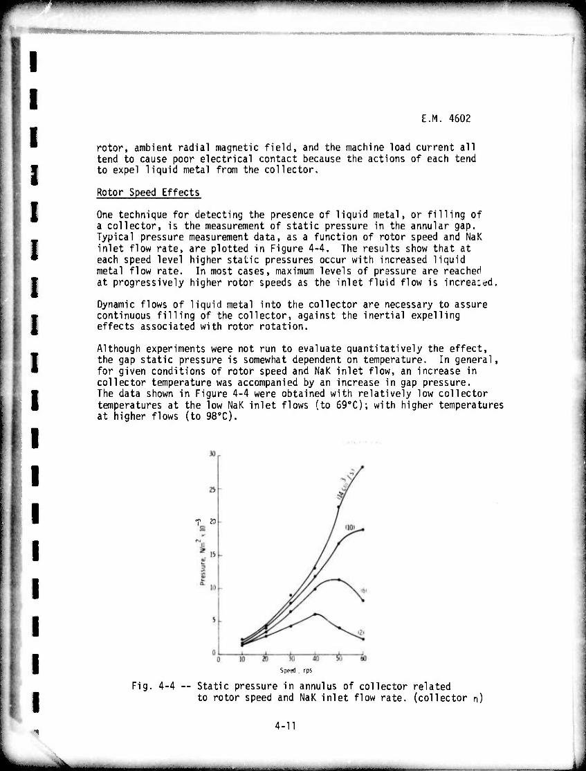
Rotor Speed Effects
One technique for detecting the presence of liquid metal, or filling of a collector, is the measurement of static pressure in the annular gap. Typical pressure measurement data, as a function of rotor speed and NaK inlet flow rate, are plotted in Figure 4-4. The results show that at each speed level higher static pressures occur with increased liquid metal flow rate. In most cases, maximum levels of pressure are reached at progressively higher rotor speeds as the inlet fluid flow is increa:dd.
Dynamic flows of liquid metal into the collector are necessary to assure continuous filling of the collector, against the inertial expelling effects associated with rotor rotation.
Although experiments were not run to evaluate quantitatively the effect, the gap static pressure is somewhat dependent on temperature. In general, for given conditions of rotor speed and NaK inlet flow, an increase in collector temperature was accompanied by an increase in gap pressure. The data shown in Figure 4-4 were obtained with relatively low collector temperatures at the low NaK inlet flows (to 690C); with higher temperatures at higher flows (to 980C).
T 20
Speed . rps
Fig. 4-4 -- Static pressure in annulus of collector related to rotor speed and NaK inlet flow rate, (collector n)
^
4-11
,....—^.—.._> . . . . ._ _j

■" " ■'■ «rnnnmimii« "Jmi i»Jmw«iiiwwiii»p»»«piPMip"wp»iw™»wpppii(»w«"ppii!W
E.M. 4602
Radial Magnetic Field Effects
Previously, it was shown that a magietic field with a component normal to the conducting surface of the collector caused localized eddy currents and an associated drag force on the rotor. These same eddy currents will also tend to place the collector fluid in a state of tension, inducing fragmentation or separation and causing problems of good electrical contact maintenance and fluid containment in the collector.
The circulating eddy current produces a magnetic field which runs circum- ferentially around the axis of the machine within the toroidal volume of liquid metal. Axially outward directed body forces, produced by the eddy current interacting with its own magnetic field, impose a tensile stress within the liquid metal. This condition tends to fragment the fluid, cause voids and degraded electrical contact in the annul us, as well as disturbances at the free surface, and expulsion of liquid metal from the collector.
The maximum axial pressure in the fluid occurs at the edges of the rotor, and it can be shown that this pressure may be expressed by the following governing expression
- mi/ ^2.4 (6) w/2 32 ['
^ w
where the new symbols are;
w/2 maximum eddy current-induced pressure in the liquid, N/m2
permeability of free space, 10" Mks units
This expression assumes a completely filled collector and that the fluid is confined against the axial expelling pressure.
An indication of the disturbing effect on fluid continuity in the collector annul us due to eddy currents is shown by experimental data presented in Figure 4-5. Gap static pressure is plotted as a function of radial field induction for four levels of NaK inlet flow rate. Significant reductions in gap pressure are shown for field strengths greater than 0.03 Tesla (the full-load operating point of SEGMAG).
As expressed in equation (6), the axial er.pelling pressure increases as the fourth power of the collector width. Thus, by increasing the collector width by 50%, such as was done with collectors 9 (1.27 cm) and E (1.91 cm), the axial expelling pressure due to eddy current effects would be expected to increase by a factor of five. This phenomenon undoubtedly accounts for why the NaK was expelled from collector t, and not from collector e, as previously discussed in section 4.2.3.
.i
.:
..
4-12
^MM ' - -- -.

'*•■ iwpw«raipii™"«n ■ppwmwF-^-" II IP«»»! I »■«••>• ^■■■•SPfWWPIWil
I E.M. 4602
o
X cvi
E
3 to
l_
*£ ra -^- oo
o
Fig. 4-5
0 .015 .030 .045 .060 .075
Radial Magnetic Field Induction, Tesla
■- Indication of liquid metal fragmentation (cavitation) caused by circulating current/self mag. fid. induced axial pressure, collector e. (u ■ 377 rad/s)
Load Current Effects
As discussed in previous semi-annual reports, a body pressure, acting to expel liquid metal in an axial direction from the collector annulus, is the result of the MHD interaction between the load current and its self magnetic field.8»10 The expression which allows calculation of this effect is given below.
PL ■ (2n-l) 6.28 x 10"7 I2 (7)
where the new symbols are:
2 P|_ = axial pressure in the liquid metal, N/m n ■ number of series load circuits (n=l for SE6MAG) I load current per unit length of collector periphery, A/m.
4 13
mmm "•"-' — - — -—- ■ i ii i untüMii'

II lilllWIllJWiiPiP'^WPIHWWIillUB^I^BWWW^I^PWWiWWmHH ~— ■ •■ ■
mmmmmm^mvmmmmmm
E.M. 4602
The axial pressure, calculated from the above expression for the SEGMA6 full-load current operating point (105 A) is 5.02 x 10³ N/p2.
Experiments were run with the large current collector test rig in an attempt to simulate the load current pressure effect, by applying a gas pressure differential across the collector annulus. Using N? gas, pressure differentials up to 3.45 x 10³ N/m2 (equivalent to a load current of 83,000 A) were achieved with the test system. At the highest pressure, a 13% reduction in viscous power loss was observed. This reduction in power is attributed to entrapment of N? gas by the NaK, possibly causing an equivalent reduction in fluid densr wetted area of contact with the rotor, NaK was confined to the annulus during performance was considered excellent.
ty and/or reduction in effective Despite this unnatural condition,
these experiments and the collector
It is readily acknowledged that surface pressure rather than body pressure was simulated during the experiments. Real testing of the load current effect will have to wait until the collectors are run in the SEGMAG demonstration generator, under short circuit full-load current conditions.
.;
..
4-H

mmii.m lumm" mim tmjm*m*mmmmm*mirjmiimi** ■IfHU*. II I mmmm^vmfm. WP^W^^fWW"
I I I I s I I
E.M. 4602
4.3 REFERENCES
1. Rhodenizer, R.L., Development of Solid and/or Liquid Metal Collectors for Acyclic Machines, Final Report for Task 1, 2 and 3, Navy Ship Systems Command, Contract No. N00024-68-C-5415, Feb. 27, 1970.
2. Mole, CO., Arcella, F.G. and Johnson, J.L., Important Problems In Applying Liquid Metal Current Collectors, Electrical Contacts/ 1973, pp. 201-210.
3. Pulham, R.J., The Study of Wetting on Copper Surfaces By NaK and Its Relation to Homopolar Machines, Research Report 72-8B6-LMSER-R1, January 4, 1973.
4. Klaudy, P., Fluid Contacts, Especially Sliding Contacts, Arc. Tech., Messen, No. 335, August 1965, pp. 97-102.
5. Harris, L.P., Hydromagnetic Channel Flows, MIT Press, 1960.
6. Frazier, W.C., Magnetohydrodynamic Flow in an Annulus, Ph.D. Thesis, Univ. of Pennsylvania, 1971.
7. Chabrerie. J.P., Mailfert, A., Robert, J., "Fining Up" Sliding Contacts, Electrical Contacts/1968, pp. 157-64.
8. Mole, C.J., Design and Development of a Segmented Magnet Homopolar Torque Converter, Semi-Annual Technical Report for Period Ending Nov. 30, 1973, Advanced Research Projects Agency, Contract No. DAHC 15-72-C-0229, Jan. 1974.
9. Hummert, G.T., Calculation of Eddy Losses in Liquid Metal Current Collectors, Westinghouse Research Memo 73-8G1-LIQMT-M1, Nov. 20, 1973
10. Mole, C.J., Design and Development of a Segmented Magnet Homopolar Torque Converter, Semi-Annual Technical Report for Period Ending May 31, 1973, Advanced Research Projects Agency, Contract No. DAHC 15-72-C-0229, June 1973.
4-15
——— ■^■.-J—-^—ai. IMMBtt

^^^^•'■•■■«»"»"■•^■«■^■■•■""•••»"""""'•■-•^•■•••■»^■■^■«^■■WÄ mw*i~^i*^mim^^w*^m^mmmmm*mmmimmmmnmmm"'m" inn IP III.II«amaf■
| l
I I
E.M. 4602
SECTION 5
LIQUID METAL SUPPORT SYSTEMS
5.0 OBJECTIVES
The objectives of this task during Phase II are: (1) to investigate the compatibility of candidate machine materials with NaK and Gain, as well as with potential decontamination solutions; (2) to perform literature, analytical, and experimental studies for the purpose of identifying suitable materials and suggesting alternate choices where necessary, (3) to design, fabricate, and test the liquid metal loop and cover gas systems that will be required in the SEGMAG generator; and (fl) to tstaolish the operating parameters and interactive responses of these systems.
5.1 PRIOR AND RELATED WORK 1 o
Previous work in this task area ' consisted of an extensive materials compatibility program, as well as efforts to define and design all of the necessary liquid metal support systems required for a homopolar ! machine with liquid metal current collectors. These support systems included the NaK handling and purification system and the cover gas purification. The necessary technology to define these systems was developed and designs were evolved for systems to be used with the
0 3000 HP SEGMAG generator. All potential candidate materials for use in SEGMAG were subjected to a rigorous NaK materials compatibility test which simulated an extreme machine environment. Materials were selected based on their ability to pass the compatibility test. Results on previously completed tests and early information on the support
•' systems design have been published.l»2
5.2 CURRENT PROGRESS
5.2.1 Materials Selection and Compatibility Studies
This task area has continued, during this period, to select and evaluate NaK compatible materials for use in the SEGMAG demonstration machine. As a result of the final design selections of the SEGMAG
,» machine, additional materials, which were not included in the original test plan, hao to be evaluated for NaK compatibility. These
J materials arp listed in Table 5-1. Compatibility studies were performed at temperatures greater than the defined machine hot spot temperature (130oC) at fixed time intervals as described in the original test plan.O .2)
A total of 503 hours of NaK exposure time at 140oC were logged on the electrostatically deposited epoxy coatings 725, 727 and 4-TK745. These
5-1
MHMMMHi ■MMMMHaMM^M^MUMMM I

■•«■W^'WWHWill, U .1 mmm***^**' "'I1 ^l • i»5^!W^^I"l«P^iP!»J»^ppp|iP|M^*^™''","WH',WW<BBl»*^»«WPPW"^i^^I"WPiW^^I^WIi^^^WP»>W»^»Wi^lllH!W" ■ IWIU I « i»W I—"•«•»TP»!«™
I
E.h. 4602
TABLE 5-1 Additional Materials Evaluated for NaK Compatibility
Material Classification
1. Electrostatically deposited epoxy stator module coatings type 725, 727 and 4-TK745 electrical insulation
2. Kapton, type H, polyimide film, stator module 2 and 3 mil thickness electrical insulation
3. Eastman 910 (MHT) adhesive 0-ring joining adhesive
materials appear to be compatible with NaK at SEGMAG operating temperatures and with the water decontamination cycle. However, it is important to note that samples 725 and 727 have physically separated from the metal substrate on which t'iey were deposited.
Preliminary test results, after 66 hours of NaK exposure at 140oC, indicate that Kapton-type-H polyimide materials degrade in the NaK environment at SEGMAG hot spot temperatures. Therefore Kapton films employed in the SEGMAG demonstration machine have been adequately protected from both the NaK and the decontamination fluid environments.
The Eastman 910 (MHT) adhesive, recommended for joining 0-ring materials, was evaluated for NaK compatibility. A 48 hour room temperature (250C) NaK exposure of 0-ring specimens joined with this adhesive showed definite attack at the joint interface, while specimens exposed to NaK at 140oC completely failed within 24 hours. Therefore, where used in SEGMAG, adequate protection from the NaK environment was provided.
A literature survey has been initiated to identify candidate machine materials compatible with Gain eutectic. ihere is little information on the compatibility of Gain alloys with materials at prototypic machine temperatures (25-150oC). No literature relating to the compatibility of Gain alloys with organic insulating materials was found, although by considering the general chemical reactivity of Gain alloys with organic systems, the attack of the liquid metal on various insulating compositions is not expected to be severe. The GEC machine will serve as a test vehicle for much of the Gain materials compatibility study program to be conducted in Phase III.
A cycle for degreasing, baking and vacuum degassina has been defined to remove cutting oil from the SEGMAG stator modules prior to applying the electrostatically deposited electrical insulation. Additionally, a technique was established and successfully demonstrated to clean and requalify stator modules which were insulated but rejected due to the presence of cutting oil which discolored the epoxy insulation.
5-2
I

wmmimmmmim^mmm- " '• m9mm\m™*\^*m*mmmmm!*mwifflfl5Q^li*ilil'''*'r!rim»' UIUNP^P^M^PM
'. E.M. 4602
As a result of this investigation the final boring operation on the SEGMAG stator assembly was performed dry, i.e., without the use of a lubricant.
5.2.2 SEGMAG Support Systems
5.2.2.1 Liquid Metal Loops
NaK loop design criteria and operational parameters were described in a prior report.2 Six 304 stainless steel, all welded NaK loops were fabricated for the SEGMAG machine. All welds were helium mass spectro- graph leak checked, and dye penetrant inspecctd. The valves were of the metal bellow-type and mechanical coupling;, to the SEGMAG were high temperature, plastical ly deformed metal fixtures. All six loops were charged with NaK to the upper level probe of the sunptank after being vacuum degassed (at lO-5 torr) at 200oC.
The loops were attached sequentia^y to a glove box and each of the centrifugal pumps was operated. The flowmeters were quantitatively calibrated by monitoring flow into graduated cylinders in the glove box. The loops were then sealed, and mounted below the SEGMAG test bed in a wheeled cabinet. Figure 5-1 illustrates one completed NaK loop, while Figure 5-2 presents the six loops in the cart prior to com- plete instrumentation. Cold trap coolant tubes and insulation have been added.
Figure 5-3 illustrates the NaK loop endurance test being performed to qualify all of the loop components. The prototype SEGMAG NaK loop has accumulated 3300 hours (5-31-74) of operation while pumping NaK at 100-200 cc/min through an open beaker in a 100 CF (V) nitrogen filled glove box. Flow control and maintainability have been excellent, and no stoppages of NaK flow due to contamination plugging have been encountered. Various test atmospheres of machine degassing products (organics, epoxies, oxygen, etc.) have been passed over and through the NaK in the open beaker, and in each case these contaminants have been accommodated by the clean-up system with the NaK remaining shiny. By comparison, static NaK exposed to the glove box atmosphere for only a few hunched hours developed a crusty contaminated surface, see Figure 5-4.
5.2.2.2 Cover Gas System
An automated cover gas handling system was fabricated for the demonstra- tion SEGMAG machine. The gas system consisted of three subsystems: 1) Main gas recirculation and purification unit; 2) Gas pump and supply for tandem gas circumferential seals; and 3) Intercollector gas system. These are illustrated in the schematic in Figure 5-5.
5-3
MM

E.M. 4602
Pia. 5-1 -- One NaK purification and supply loop for the SEGMAG generator
Fig. 5-2 -- Cart containing six NaK loops for installation on the test bed for the SEGMAG generator
5-4
RM-60863
^MMMM^M

*t
.. E.M. 4602
Fig. 5-3 -- NaK loop endurance test set-up beneath glove box
Fig. 5-4 -- NaK reaction chamber in glove box with purified NaK from loop endurance test. (Note oxidized surface on static NaK main- tained in a beaker within glove box.)
5-5
RM-60862
mamlm. J

E.M. 4602 3
s
s,£
pgH Is L CD !•
T 2S -T
8
:
i»-
s.
Q. >
L
LIMV i 8 ,
in
>! to
in ra
s- 0) > o o to < 2: LÜ U1
I
LT)
ir>
CD
V.
I 4
; I
•*
5-6
■- - - - - ■ ■■ - — -- ■

E.M. 4602
i .
i
i
i
i
The main gas recirculation and purification system consists of a Westinghouse designed commercial unit with tandem (parallel) towers containing Dow resin and molecular sieve materials. Dry nitrogen is thus circulated through the machine, and through one tower at a time. The tower removes oxygen and moisture to levels of 1 ppm and below. Refrigerant-cooled heat exchangers were added to remove con- densible vapors (NaK vapor, organic compounds) that could leave the machine and affect the active resins. One tower may be automatically regenerated while the other is on-line. Flowmeters and control valves balance the flow and circulation of dry nitrogen through the machine housing. The pressure is maintained at 4 psig and high and low pressure alarm interlocks are provided. A continuous sample of gas is drawn and sampled for oxygen and moisture purity, and a trace recorder is employed to indicate oxygen levels. An alarm interlock is provided for the detection of oxygen levels above 10 ppm (V). Cover gas can be circulated through the system at 0 to 35 SCFM. Experimental operation of this unit with the SEGMAG showed it to perform better than expected, and to maintain machine cover gas purities around 1 ppm (V) for oxygen and even better for moisture during machine temperature excursions reaching 90-100oC. Thus the NaK inside the machine is not subject to oxidation and oxide problems.
A second gas system operates from the main gas system to distribute the nitrogen. A mechanical, bellows pump is employed to extract gas from the main gas system recirculation lines and to raise the pressure to 5-7 psig (main system at 4 psig) for insertion into the tandem circumferential shaft seals. (See Section 6.0.) Dry nitrogen is thus supplied to the seals at 1-2 SCFH. Half of the gas is lost to the environment, half returns to the machine housing for recirculation and purification. A gas pressure controller automatically supplies cover gas makeup for losses, as well as maintaining system pressure at 4 psig.
A third gas system, also illustrated in Figure 5-5, called the inter- collector gas system, is employed. A mechanical, bellows gas pump is employed to pull cover gas down the NaK drains of each current collector (gravity drains to a sump tank) and thus assist drainage. This gas is removed from each loop at the sump tank (the void space above the NaK level), drawn through a vapor trap, and then forced by the gas pump through 6 flowmeters, and reinjected into the intercollector gas gaps between the rotor and stator. Once in the gas gap, the gas divides and flows into the adjacent current collectors, sweeping aerosol and NaK vapor. The gas then exits via the NaK drains and repeats the cycle. Contaminants which enter the gas are removed by reaction with the NaK, the reaction products floating on the NaK surface in the sump tank.
Trial operation of the cover gas system, first with the glove box (100 CF), and subsequently with the SEGMAG machine (less than 1 CF), have confirmed its operation. For the initial startup, a roughing pump vacuum was applied to the machine while it was heated to 70-80oC (see Section 5.2.2.3 Water Cooling System). Following removal of the
5-7
_,_-_ —■-- ■ . , , ,

E.M. 4602
I I
volatiles. moTsture, etc., in this fashion, a dry nitrogen gas purge was initiated. Monitoring of the effluent purge gas for oxygen and moTsture showed both to be below 100 ppm (V), and the main cover gas recirculation system was started. This system operated continuously once the machine was clean of oxygen and moisture. The shaft seal * system was activated only prior to and during rotation. The inter- collector gas network was only active during NaK circulation through tne machine. The on-line oxygen and moisture monitors operated J continuously. K
5.2.2.3 Water Cooling System '••
A water cooling system was fabricated to cool the SEGMAG current col- lectors and leads during performance testing. An unusual requirement -* was placed upon the water system, thus a simple once through coolant pass could not be employed. Previous experimental evidence from the ful scale current collector test stand illustrated that NaK retention in the collectors was most efficient when the collectors DperatPd above a certain critical temperature.2 Furthermore, this temperature is also dependent on collector rpm.
..
.;
Figure 5-6 illustrates the main SEGMAG cooling water system. Water is SlüS.SS ar?S,nd,an internal loop at 32-36 gpm (to maintain a low AT across the collectors and leads) through the SEGMAG machine. Heaters are provided to raise the recirculating water to the aforementioned critical temperature. The heaters are also beneficial in tie cover gas cleanup and degassing cycle prior to NaK injection (see Section 5 2 2 2
ZI' ?hS Syltm)- When the SEGMAG housi^ is at the critical tern era- "A" in n ec lyStem S stabilized- A temperature sensor at location -, val.P "v?"Urew ; SÄ1S ' contro;ier' which operates a proportioning HII!I I ' • !lve u2 0pens or closes 1n response to the controller •* signal to maintain the set temperature in the water system As "V2" opens hot water is lost at "V2" and cooler water is admitted at "VI" Excellent collector thermal control has been demonstrated during experi-
excepis0!^^1?^^ rthiS T^Ti TOtal SyStem heat remova1 capability exceeds 120 Kw(t). Current collector temperatures of 25 to 90oC can be controlled to within + 20C.
Auxiliary system cooling for (1) Drive motor gear box; (2) Shunts for short circuit testing; and (3) NaK loop cold trap cooling are provided header? Strai9ht-throu9h flow Wew from separate water supply
5.2.2.4 Instrumentation
Instrumentation for the SEGMAG test site (Figure 5-7) can be best described by functional grouping. For the 6 NaK loops, 4 loop temperatures (sump tank, pump motor, cold trap entrance, SEGMAG inlet)
5-8
, . .. _.

fl
a
n
..
i 1
E.H. 460?
® O
CL \S\ E c a> <i>
r««
I _> > en C
CD J\
(g>.
tv
?>"<$>
r
^5
I Hgh
<^
a. E
GO
o —^ CO
F O 3 i- O) a>
o > re
Q. o >
"B^
— a> :> cn ra HD n n cu ^> ra t _> C9 n3 cn
TJ C ci > -_ l_> 3
Jit tr l/l a> o uo > a) O)
^5 .£- ra L.
o QQ a.
4-> CO
>> (/) S-
cu ra 3
o o o
E
I 1
-
0
■g o
T \
■^
5-9
HMI riHAMtaüA^ÜMiUH ■ - -■■-■■ ■

^
E.M. 4602
Fig. 5-7 -- Instrumentation and control panel for the SEGMAG generator test bed
are monitored and recorded on a 24 point strip chart recorder, along with the NaK flowrate through the SEGMAG and the NaK level in the sump tank. Alarms are sounded for over-temperature, low or high NaK level, loss of flow, etc., conditions. These alarms (and all others to be described) are indicated by separate lights on an annunciator panel, as well as by an audible signal. SEGMAG temperatures (each current collector, bearing, shaft seal) were also monitored and alarmed for high side excursions. Cover gas flowrate through the machine, the shaft seals, and the intercollector network are monitored, as well as their respective pressures and temperatures. Also, cover gas purity (oxygen, moisture) is continuously monitored, recorded, and alarmed for high-side contamination.
Cooling water temperatures into the machine, and out of each current collector, module lead, and excitation coil are also monitored, recorded and alarmed for high side excursions, as well as for flowrate. The drive motor input power, SEGMAG rpm, generated voltage and current are also monitored. The latter condition is measured by the temperature of and millivolt drop across calibrated shunt bars. The SEGMAG field current is shown on the instrument panel, as are the M-G excitation settings (amps, volts) to maintain the SEGMAG excitation current. Additional auxiliary instrumentation is employed to evaluate the operating condition of various pumps and blowers, contacts, power relays, machine vibrations, etc. Figure 5-7 presents the main temperature and machine control instrumentation for the test site.
5-10
A

E.M. 4602
Two modes of emergency shutdown are incorporated into the instrumentation and control systems: 1) An automated shutdown; and 2) Manual shutdown. The automatic shutdown sequence is interlocked with the alarm and annunciation network, and will when operative, shut down the test site in a logical, timed sequence. The manual shutdown mode is setup for non-emergency conditions, for normal termination of experiments.
U
LI .1
5.2.2.5 Power Train
The drive motor for testing the prototype SEGMAG generator is an 1800 rpm, 150 HP wound rotor, three phase, induction motor with a secondary four step resistance controller for speed control. Finer speed control for low speeds is effected by the employment of a powerstat. The drive motor is coupled to the gear box with a toothed, flexible coupling via shrink fit mounts to the shafts. The speed increaser gear box (1:2.2) has sleeve bearings, and has forced lubricant, with a water cooled lubricant heat exchanger. The coupling to the SEGMAG is the same as that to the drive motor.
A 50 HP AC motor is used to drive the DC generator which supplies up to 1200 amps to the SEGMAG field coils.
5.2.2.6 Test Bed
A steel reinforced concrete platform 31 x 5' x 12* provides support for the SEGMAG machine and drive system. The test platform was welded from 4-irich angle and 6-inch channel steel of 3/8-inch thickness. The platform is 40-inches high to permit the installation of NaK, covergas, and cooling water services below the SEGMAG, gearbox, drive motor power train. This bed, together with the drive train and NaK loops, is shown in Figure 5-8.
;:
1
I I
5-11
^^mmtmammtmi^.

E.M. 4602
Fig. 5-8 -- Test bed for SEGMAG generator showing drive train (150 HP motor, gear box) and NaK loop cart
1
I t
1
•
i
5.3 REFERENCES
1 "Design and Development of a Segmented Magnet Homopolar Torque Converter," ARPA Contract DAHC-15-72-C-0229, Semi-Annual Technical Report for Period ending November 30, 1972, (Westinghouse Report No. EM 4471), December, 1972.
2 "Design and Development of a Segmented Magnet Homopolar Torque Converter," ARPA Contract DAHC-15-72-C-0229, Semi-Annual Technical Report for period ending November 30. 1973, (Westinghouse Report No. EM 4559), January, 1974.
5-12

._
■'
E.M. 4602
SECTION 6
SEAL STUDY
6.0 OBJECTIVIS
The primary goal of this task is to develop a shaft seal to avoid contamination of the SEGMAG machine's containment vessel by either air, moisture, or the hydrocarbon-based fluid used for bearing lubrication and thereby prevent contamination of the liquid metal system. In addition, excessive losses of the machine's inert cover gas to the atmosphere must be avoided.
The specific objectives of this task during Phase IT are as follows:
• Construct a seal test stand capable of evaluating the performance of tandem circumferential seals in a dry, inert environment.
t Perform functional seal tests at 3600 rpm in dry nitro- gen gas on seal units equipped with composite-type seal materials capable of retaining their self-lubricating ability in a no-moisture environment.
t Perform functional endurance tests on that combination of seal design and material which demonstrate optimum performance with respect to gas leakage, seal wear, operating temperature, and NaK compatibility.
6.1 PRIOR AND RELATED WORK
Studies performed during Phase I indicated that a tandem circumferential seal, or bore seal, was the prime candidate for satisfying the requirements imposed on the primary rotor shaft. The circumferential seal not only exhibits the ability to withstand high velocity rubbing at its primary sealing surfaces, but also trie ability to provide a high degree of sealing effectiveness. Its design conserves weiyht and space, provides virtually unlimited shaft travel, and is easily assembled. Figure 6-1 is a schematic of this seal type.
With regard to material selection for use in these seals, care must be exercised to insure that the self-lubricating composite employed retains its lubricating ability in a no-moisture, inert gas environment. Standard grades of carbon-graphite seal materials exhibit extremely poor friction- wear characteristics in dry argon. Face seal screening tests on candidate seal materials for use in the primary rotor shaft seals of homopolar machines indicated that two polyimide matrix composites exhibit satis- factory friction-wear characteristics in the inert, no-moisture environment required for these machines. The composites contain solid lubricants,
i
^ 6-1
■MM ^MM^MMM , J

E.M. 4602
such as molybdenum disulphide. Teflon, md graphite, as fillers. Both materials were also found to be compatible with NaK at a temperature of 108oC Seal segments suitable for use in tandem circumferential seals were fabricated from these materials.
A seal test stand was designed during the Phase I effort of this program. Through the use of a 2:1 pulley ratio, the test stand is capable of performing experiments on various seal configurations over a 7000 rpm speed range in inert, bone-dry environments. Leakage rates, operating speed, and seal and bearing temperatures are continuously monitored. The test stand is capable of evaluating seals for shafts ranging in diameters from 2 to 6 inches. Figure 6-2 is a photograph of this test rig.
A total of four tandem circumferential seals were purchased for functional testing purposes as well as for use on the SEGMAG machine. Testing results on these units have indicated that seal leak rates can be held to 0.02 cfm or less and that the use of carbon-graphite seal materials in these units is unsatisfactory when they are applied in dry, inert gas environments.
6.2 CURRENT PROGRESS
The test program for functional seal testing has consisted of three phases:
1) Candidate seal materials are to be evaluated with regard to their ability to operate effectively in an inert, no-moisture environment.
2) Concurrently, these materials are evaluated with respect to their compatibility with NaK at room temperature and, where appropriate, at elevated temperature.
3) Finally, the most promising materials are fabricated into actual seals and tested extensively with respect to operating speed, runner design and material, and load pressure. The results will be compared against those obtained on units employing standard carbon-graphite materials. Parameters monitored during these tests include seal wear, leakage, and operating temperature. Progress in these areas is described below.
:
:
..
6.2.1 Face Seal Screening Tests
All face seal screening tests on candidate seal materials have been completed and the results reported in the previous semi-annual report. NaK compatibility studies on these materials have also been completed, and reported.
6-2

E.M. 4602
Mi l ROüE M o^S
EAL FACES ..._
Fig. 6-1 -- Schematic of typical tandem circumferential seal
.-
Fig. 6-2 -- Tandem circumferential seal test rig
6-3
E.M. 4602
6.2.2 Functional Seal Tests
3 i
1 During this reporting period, three functional tests were performed on tandem circumferential seals designed by the Stein Seal Company. The first two experiments were performed on seals equipped with USQ-b/ » carbon-graphite segments in order to obtain bench mark performance data on standard seal designs. The third experiment was performed on a seal of identical design but equipped with segments fabricated from Vespel SP-211.
The results of the first functional test are presented in Figure 6-3 as a curve plotting seal leakage in cfm versus operating time. The experiment was performed at 3600 rpm with a 5 psig nitrogen gas (< - 450C dew pt) feed maintained to the seal. As expected with carbon-graphite in such an environment, severe seal material wear occurred after approximately 25 hours of operation. Performance of the seal up to that point was excellent, with the measured leak rate holding steadily at 0.005 cfm. As discussed in the previous semi-annual report, a similar result was observed upon operating the Koppers Company tandem circumferential seal under identical conditions.
The results of the second test performed during this reporting period are presented in Figure 6-4. Seal material was again US6-67 carbon- graphite.
The test was performed successfully at 3600 rpm with five psig nitrogen gas being fed to the seal, and was permitted to operate continuously for a period of 500 hours. After a 3 hour run-in period, seal leak-rate stabilized at 0.021 cfm and remained at this level for the duration of the experiment. This rate is equivalent to the consumption of one standard gas cylinder per five day period for a set of two tandem seals. It should be pointed out that the test parameters incorporated in this experiment-including seal material-are identical to those used in test #1, which failed due to carbon dusting after 25 hours operation. The only difference between the two experiments was that the J nitrogen gas feed in this endurance run was first passed through a water bubbler to raise its dew point to 0oC. At this level, sufficient moisture is added to the nitrogen to sustain carbon-graphite dry lubrication. While this technique cannot be used for SEGMAG, this experiment clearly demonstrates, a) the long-life capabilities and sealing efficiency of the tandem, circumferential seal design, and b) the need for a seal material whose seif-lubricating characteristics are not dependent on the presence of moisture or oxygen in its environment.
The final test performed during this period utilized a Stein circumferential seal equipped with segments facricated from the Vespel SP-211 polyimide- matrix composite. The seal was operated at 3600 rpm while being fed dry nitrogen (dew pt < - 450C) at a feed pressure of 5 psig. A total, accumu- lated life of 800 hours was achieved on this seal with no segment dusting or significant wear. Figure 6-5 presents a curve summarizing the results
6-4

ü E.H. 4602
0 .:
n Fig. 6-3 -- Leak rate versus running time for tandem circumferential
Stein Seal; carbon-graphite USG67 3600 RPM-N9 gas feed < - 450C Dew pt. '
0
.:
i i
-*
.060
.055
.050
1-045 ar.040 S .035
.030
.025
.020
.015
.010
.005 0
i—\—\—r i r n—i—r
-Speed Increased i to5000RPM -
J I I I \ I I I I I L .L 0 25 50 75 100 150 200 250 300 350
Running Time, hours 400 450 500
Fig. 6-4 -- Leak rate versus running time for tandem circumferential Stein seal; carbon-graphite USG67 3600 RPM - N9 Gas Feed <-450C Dew pt,
6-5
■-- • --• -^ — - -■

—p. ■»|i«miii"j.>p.w \immmm<wm*m><wwui■ .■ LI.IHI nmij
E.M. 460.
.1
of this test in the form of seal leakage versus running time. The seal was initially permitted to operate for a period of 100 hours prior to test shutdown for segment inspection. After a period of 10 hours, the seal's leak rate stabilized at 0.015 cfm. Post-test inspection of seal and runner surfaces revealed highly polished sealing surfaces and an excellent film established on the runner surface. Subsequen* to this experiment, the seal was again installed in the tester and subjected to a continuous endurance run of 300 hours at 3600 rpm and the same 5 psig dry nitrogen feed as in the previous run. At test shutdown, seal leak-rate was holding steadily at 0.01 cfm. Examination of seal surfaces revealed no significant segment wear and excellent runner filming.
Finally, the seal was again reinstalled in the tester and operated continuously until a total life of 800 hours was reached. Satisfactory leak rates ranging from 0.005 to 0.01 cfm were measured during this interval. As a part of this final experiment, the oxygen content of the nitrogen leaking past the seal dam was monitored. A level of 2 ppm oxygen was held throughout, indicating no air diffusion past the sealing dam. Upon test termination, this seal was removed from the test stand and stored for use on SE6MAG.
.
.
„
. i
6-6
.-^ -«. mm* Mi
.
Curve fci6l2l-
004 .002
0 0 5 10 15 20 25 30 35 40 45 50 55 60 65 70 75 80 85 90 95 100 Running Time, hrs
300 500 700
0 Ü
Fig. 6-5 -- Leak rate vs. running time for tandem circumferential Stein seal - Vespel SP-211 3600 RPM - 5 psig Np Gas Feed <-450C Dew pt.