ad-756 726 helicopter blade flutter norman … · manual on aeroelasticity ... v nondlmensional...
TRANSCRIPT

MM WHHH&mm mammimm MMMMMWIMIMMll
AD-756 726
HELICOPTER BLADE FLUTTER
Norman D. Ham
Advisory Group for Aerospace Research and Development Paris, France
January 1973
DISTRIBUTED BY:
mü] National Technical Information Service U. S. DEPARTMENT OF COMMERCE 5285 Port Royal Road, Springfield Va. 22151

T 1j'
0
I
t
oec<O
c<?
;oiO
o
AGARQ-R-607
ADVISORY GROUP FOR AEROSPACE RESEARCH & DEVELOPMENT
7RUEANCELLE 92200 NEUILLY SUR SEINE FRANCE
AGARD REPORT No. 607 on
Helicopter Blade Flutter
•>> _
N.D.Ham u u ^
NATIUNAL TECHNICALinformation service
r . . dMAR 14 1973
usitstgroTsl^ B 1
NORTH ATUNTIC TREATY ORGANIZATION
DISTRIBUTION AND AVAILABILITY ON BACK COVER
i AGARD R-607
NORTH ATLANTIC TREATY ORGANIZATION
ADVISORY GROUP FOR AEROSPACE RESEARCH AND DEVELOPMENT
(ORGANISATION DU TRAITE DE L'ATLANTIQUE NORD)
AGARD Report No.607
HELICOPTER BLADE FLUTTER
by
N.D.Hani
Massachusetts Institute of Technology Cambridge, Mass. 02139, USA.
Revision of Part III, Chapter 10
of the AGARD MANUAL ON AEROLLAST1C1TV
This report was sponsored by the Structures and Materials Panel of AGARD.
I
THE MISSION OF AGARD
The mission of AGARD is to bring together the leading personalities of the NATO nations in the fields of science and technology relating to aerospace for the lollowing purposes:
- Exchanging of scientific and technical information;
Continuously stimulating advances in the aerospace sciences relevant to strengthening the common defence posture;
- Improving the co-operation among member nations in aerospace research and development;
Providing scientific and technical advice and assistance to the North Atlantic Military Committee in the field of aerospace research and development;
- Rendering scientific and technical assistance, as requested, to other NATO bodies and to member nations in connection with research and development problems in the aerospace field;
- Providing assistance to member nations for the purpose of increasing their scientific and technical potential;
- Recommending effective ways for the member nations to use their research and development capabilities for the common benefit of the NATO community.
The highest authority within AGARD is the National Delegates Board consisting of officially appointed senior representatives from each member nation. The mission of AGARD is carried out through the Panels which are composed of experts appointed by the Natioral Delegates, the Consultant and Exchange Program and the Aerospace Applications Studies Program. The results of AGARD work are reported to the member nations and the NATO Authorities through the AGARD series of publications of which this is one.
Participation in AGARD activities is by invitation only and is normally limited to citizens of the NATO nations.
The material in this publication has been reproduced directly from copy supplied by AGARD or the author.
Published January 1973
533.662.6
w Printed by Technical tailing and Reproduction Ltd
Harford House. 7- V Charlotte St. London WIP I HD

»^Ti^»-^fW»'^""T^n^'^TTTv^ir*y*yBf*yB^^'^"-f>
■
NORTH ATUNTIf TRhATY ORGANIZATION
ADVISORY GROUP FOR AEROSPACK RESEARCH AND DEVELOPMENT
(ORGANISATION DU TRAITE DE L'ATLANTIQUE NORD)
ERRATA
AGARD Conference Proceedings No.80
SYMPOSIUM ON UNSTEADY AERODYNAMICS FOR AEROELASTIC ANALYSIS OF INTERFERING SURFACES, PART II
Paper 12 UNSTHADY AERODYNAMICS FOR WINGS WITH CONTROL SURFACES by H.Tijdeman and R.J.Zwaan.
1. Page 12-2 Section 2-2, 4th paragraph. 3rd line; add after ".... inboard control surface'*
"(AR = 1.53, A,, = 50.1°, t = 0.25, ltjp/lr0(„ = 0.573 (Ref.12)).'
2. substitute the reverse of this sheet for page 1 2-H.

— —— rr 12-8
Q Q U Ul cr
hi 2
u eg
-J
6 OO
ii a g
0 5^
I c
c
Mo
^ Cd
« o
2 s
'£ I
il - I •a cd 1)
si,
a QU
^
ö ■I 8
(0 CO o II
0 2 *
cd O
XI c
so c
5 — 13
§ c 0 3
X>
■o
c 3

PREFACE 5
■
Professor Norman D.Ham is presenting here a revised and up-dated version of the article he wrote in 1967, under the same title, for the Aeroelasticity Manual, and which was included in Chapter 10 of Volume 111 the following year.
Since that date, many advances and developments have been made regarding the vibration theory of the rotating parts of helicopters, and the undeistanding of the instabilities created in flight by these vibrations. For the Manual to continue to fulfil its information mission, it had become necessary to bring it up-to-date. Professor Ham, who had been the first one to draw attention to developments in the field covered by his article, accepted this task himself; no one could have brought it to a more successful issue.
New questions i.a'v* been raised and solved. The analytical methods used to convert in-flight vibrations into equations and to detect aeroelastic instabilities are presented for hinged and locked blades, for take-off or cruise flights. The reasons for such instabilities are considered in detail, and efficient means prescribed to avoid them. Besides conventional type flutter, a large section is devoted to stall flutter. The text is illustrated and completed by many diagrams giving the results of calculations carried out in the United States.
Considered from a general standpoint, this article which is intended to replace that of 1968, provides an excellent survey of the data available in 1972 on the vibratory stability in flight of hel copters, and should therefore prove extremely useful to helicopter engineers and manufacturers.
R. MAZET General Editor of the Manual on Aeroelasticity
PREFACE
Le Professeur Norman D.Ham presente i:i une edition revisce et complötee de Particle redige par lui sous le meme ti re en 1967 pour le Manuel d'Acroelasticite et qui a pris place au Chapitre 10 du Volume ill I'arinee suivante.
Depuis cette date, de nombrcux progri's et developpements avaient ete apportes ä la theorie des vibrations des organes tournants des helicoptcres et a la connaissance des instabilites auxquelles ces vibrations donnent naissance en vol. Pour que le Manuel continue de remplir la mission d'information qui lui a ete assignee, il devenait necessaire de proceder ä une remise a jour. Le Professeur Ham, qui avait le premier signale revolution des connaissances sur la matiere de son article, a bien voulu assumer lui-meme ce travail; nul ne pouvait mieux que lui le mener ä bien.
Des questions nouvelles sonl posees et resolues. I.es me'lu)de> analytiques permettant de mettre en equations les vibrations en vol et de decelcr les instabilites aeroelastiquts sonl presentees pour des pales articulees ou encaslreL-s. pour le vol au decollage ou en croisiere. Les raisons de ces instabilites sont examinees en detail et des moycns efficaces sont preconises pour les eviler. A cöle des flotlements de types classiques. une large place est fait au flpltement de decrochage (stall flulter). De nombrcux graphiques Iraduisanl en courbes les resultals de calculs effectues aux USA illustrem et complelent le texte.
D'une fa(,on generale, eel article, qui osi destine a se subslituer a celui de 1968, esl une excellenle synthese des connaissances disponibles en 1972 sur la stabilite vibratoire en vol des helicopteres el doit rendre, .i ce litre, d'uliles services aux constructeurs el aux Ingenieurs specialisles de ces appareils.
R MAZIT Kdlteur (leneral du Manuel d'Aeroelaslicili'
CONTENTS
Page
PREFACE '«
SUMMARY !
SYMBOLS '
1. INTRODUCTION 2
2. FLUTTER OF HINGED BLADES 2
3. FLUTTER OF HINCELESS BLADES 7
4. STALL FLUTTER •'
REFERENCES ,3
FIGURES 16
CONTENTS OF MANUAL ON AEROELASTICITY 27

liiLICOPTER ÜLADE FLUTTER
by
.Jorman D. Ham Professor
MIT Cdmbridre, Mass. 02139
U . J . A.
SUMMARY
Methods of analysis of helicopter blade flutter for both hinped and hlnpeless blades are presented. The major types considered are bendlnp;-torslon flutter, flap-lag flutter, and stall flutter. Uotli hover and forward flight are considered. Means of avoiding flutter are described.
SYMBOLS
a
b
c
gU)
g,.(t)
>:
ni(r)
x
x.
r or s
z
CU) CT L
F
G
I
e M(r)
blade section lift curve slope, per radian
blade section senl-cnord
blade section chord
displacement of blade first elastic bendinc mode
displacement of blade kth bendinf mode
blade section reduced frequency, siR(x + u sin*)
blade spanwisc running mass, slugs per foot
blade nondinenslonal spanwise station
chordwlse displacement of section aerodynamic center from elastic axis, positive forward
cnoruwise displacement of section canter of gravity fron elastic axis, positive fc-.rwara
spanwise distance along blade from axis of rotation
vertical distance from rotor nub plane
lift deficiency function including blade wake effects
rotor tnrust coefficient
blade bending modulus of elasticity
real part of lift deficiency function
imaginary part of lift deficiency function
blade section second moment of area, flatwise bending, or ratio IQ/IT
blade moment of Inertia about flaprlnr: nlnre
blade section moment of inertia about its center of gravKy
nondlmensional blade product of inertia ajout flapping anu elastic axes
nondlmensional generalized mass of ktn benuinf; node
blade section moment of inertia about its elastic axis
blade bending moment at r
blade section aerodynamic moment about elastic axis
R
T
a
a.
n(r)
nk(r)
rotor radius
rotor thru?'
blade section angle of attack blade section wean angle of attack
displacement of blade rigid flapping mode
blade mass constant, or Lock number, *-*
mode shape of blade first elastic bending mode mode shape of blade kth bending mode
rotor advance ratio V/QR
'i

v nondlmensional root of bendinR-torslon characteristic equation
v, nondlmensional rotatlnR natural frequency, kth bendlnR mode
u Imaginary part of v
u rotating natural frequency, kth bending mode
u nonrotatlnf; natural frequency of blade torslonal motion
p air density
o rotor solidity
0 blade pltcn anpile
'.. dampinp; coefficient of blade torslonal motion, divided by the critical damping coefficient
ii rotor rotational speed, radians per second
(/ rotor blade azimuth anple, zero when reference blade is downstream
0 (x) fundamental torsion mode shape
1. IHTRODUCTICW
Tne flutter of helicopter blades can be classified under the following categories:
(1) Flutter of Hinged Blades (2) Flutter of i!irip;eless Blades (3) Stall Flutter
The analysis of case (1) differs from tne classical analysis of the high aspect ratio wing due to several Important factors. The high centrifugal force field experienced by the rotating blade provides funaamental bending and torslonal stiffness effects a.nd also important coupling effects under certain circumstances. Also, the presence of the returning wake beneatn the rotor at low flight soeeds leads to unsteady aerodynamic ef- fects that are substantially different from those characteristic of fixed wings. Finally, tne variable velocity field encountered by the blade in forward flight generates important tine variations in the velocity- and amplitude-dependent restoring forces acting on the blade.
The flutter in case (2) is due to the coupllnp; between blade flapwise and lagwise ROtior. whicü may lead to instability at large blade-pitch settings. This instability can occar at any flight sueed provided the damping of the chordwlse motion is below a certain value.
The instability associated with case (3) is due to the adverse time phasing of tne aerodynanlc torslonal moment resulting from the loss of blade bound vortlclty during torslonal motion at hign angles of attack. The coMplex nature of the phenomenon precludes an analytical representation of the unsteady airloads at the present time, but the pre- ulctlon of regions of instability is made possible by the application of experimental two- dimensional uata.
ence CD A useful survey of tne various instabilities of rotors is presented in Refer-
d. FI/ufTüH ÜF Hi;iOED BLAUtJ
a. Equations of Motion
Consider ben ling out of the plane of rotation of the flexible, untwisted, un- tapered rotating blade snown in Figure ;i). The bending moment at r due to forces at s is
M{r)--f \ d^s) -z(5)m(s)] (s-r)ds
- j sß2 m(s) [z(s)- 2(r)l ds
differentiating twice with respect to r yields
Zlr) /•" 2 dz(r) ? m($)ds rft m(r)
dr

M(r) = El (r) d2Z
dr2
dr' EKrl
dr?
^2 /.f
dr2 K m(s) sÜ2ds+rn2m(r) — +m(r)z = Cl
dr dr (1)
the differential equation for a beam bending in a centrifugal force field.
Assume a series solution in terms of normal bending modes.
GO z z = Z 77k (r)gk(t)
(2)
For free vibration of the rotating beam, neglecting aerodynamic damping, aT(r)/dr » 0. Substituting Eq. (2) into Eq. (1)
£ ..2 v JT d2 (^d^ d ^ rR ^ o2„. ^o2 ^A X < —rlEI—=— 5— m(s)sii ds + rm(r)ß —— (Ti \Ldr2 \ dr2 / dr 2 Jr dr J \*™\\
quency Assuming simple harmonic motion at the kth rotating undamped natural bending fre-
Qk e i^flt
2 n2- i^kflt ■,/L2ft2gl k 'li
[ 1 2 n2 '^k 9k
Therefore, the bending equation of motion becomes
CD CO v 2 n2 l? .. . dT
k:| k k k Ml
As an approximation, assume that all blade torslonal flexibility is concentrated at the root (often true due to control system flexibility: the general case of distributed torsion is discussed in Reference (2)). Then, for the geometry of Figure (2), the coupled blade bendlng-torsion equation of motion is
00 - ^ z i 2dT .. 'k % ± k 'k^k I 1 dr k:| k:|
(3)
Multiply all terms of Eq. (3) by nk and Integrate from 0 to R:
/•R /•R Mk ^'k + Mk "'ß ^k" (a*« Ö)/^hxIdrS/ ^dr
o o
(4)
where R
o mr,k dr
/o mnjn,, dr
k - 1, 2, ...
J f* k
due to the orthogonality of the n^'s.
In practice an adequate representation of the blade bending motion Is often ob- tained in terms of the first two modes only. On this basis the bending motion of an articulated blade Is described by
rß + ng (5)
where r ■ rigid flapping mode n » first elastic mode
Then If I = Mj ; I2 - M2/I ; Ix - (1/I1);^ ninkxI dr, EQS. (^) become, after division by I, n , eind since v, ■ 1,
Ö +(1 J 9 T fl - ! r" r dT H (6) _ —ir f r — or
I- -~ + I.i/fg - !„ -4 - I. fl = —'— /" T, iL dr 2 fl2 2 2 "z fl2 x2 I ß2 j v dr a (7)
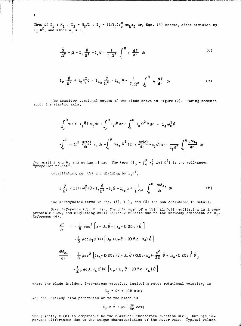
How consider torslonal motion of the blade shown in Figure (2). Taking moments about the elastic axis.
£3 R R
-/* m (z-Xjfl) Xjdr + /" lo0dr+ /* Ioß2edr + lewo
20
-i rmil — xTdr-l mxii (z-r xT0 dr = ——=■ / -~- dr J. dr I J I dr I j n2 J dr
R „2 ^ T „2, for small z and 6, ana no lag hinge. The term [I + / xT dm] n 6 is the well-kno "propeller roaent". 0 0 -^
Substituting Eq. Cj) and dlvldlnR by I.n ,
±tI(u.!)e-i,i,-Kß.s%r-^ r"^ 1 r dMA, Ifl +n'^o )Ö-1^-1.0 -I._g= y^ j -äT^-dr (8)
The aerodynamic terms in Eqs. (6), (7), and (8) are now considered in detail.
From Reference ii), P. 27^, for un; c span of a thin airfoil oscillating in incom- pressible flow, and neglecting small unsteady effects due to tne unsteady component of U_, Heforence (4),
— ----jlp ^oc2 [z+ UTe-U.-0.25c) e ] dr ö >- i A
-i pacüjC'M [up +UTe + (0.5c-xA) fl]
dMA. lor c2 " 2 -T —J--- -g-^acZ [(xA-0.25c)z-UT0 (0.5c-xA)-32 e-(xA-0.25c) flj
+ ^acUTxAC'(K) [Up+ UT0+ (0.5c- xA)fl]
where the blade Incident free-stream velocity, including rotor rotational velocity, is
U,, » Qr + u^R siniji
and the unsteady flow perpendicular to the blade is
Up ■ z + ufJR -jp cosij)
The quantity Cik) is comparable to the classical Thcodorsen function C(k), but has im- portant differences due to the unique characteristics ojf the rotor wake. Typical values

I of C'dt) are shown In Figure (3), taken from Reference (5).
In the present analysis, the virtual mass terms proportional to 2 and Ö are neglected for simplicity. They can be included if desired by appropriate adjustment (usually of the order of a few oer cent) of the values of the blade inertial constants.
The aerodyiamic terms can be expressed as follows:
C'(k) j j x2-|- dx +^sin f j x-^ dx j
= y C'(k) [('+M2)+-|-/isinl//- /x
2cos2Vj
-- ^ CMkT [^ MCOSV + ^/x2sin 2^]
i ß/a. 8
■:
Y m2 - T
m e/a,
me
mß
v r ^1
The 9/n term is normally neglected for c << R. The coefficient C (k) is a mean value based on condition? at the blade three-quarter radius. Also
p-/ ^^"^^'"Vfl n"',lni/n ^""V,0-"1*/-^9
where . .
.1
ßz
%
£[Msint][-^4(0.5|-->)C'U)]#(-£d,
-- |-C'(k) [/(-jj-) x2dx^ fSsirffj ^dx] +y ^Öö/x sin t^ j x ^ d>
= -^ CMlT) ^/x2sin 2^ j" -|dx + ficos* j x -^ dx j
Again, the e/n term is neglected for c << R. Finslly,
.R dM. 1
I ß2
/ A fl Ä Ö —^-L-- -M. -w-M. -K--M. J--Mfl)8 -Mfl 9 -M. g dr e/a n ß/a n q/n ß ß 9 g

6
where
M,
J/a=-i:^J7^[J(',^'",t'"in*J['R<"1] j =--|--^ C'(k) [^cos* . ^2sin 2*]
-^ c'lk) [l+3>i8in »J'+ 3/izsin2 fl M, -f
Note that In Corward flight, when the flow direction reverses periodically with respect to portions of the blade, x./R "0.5 c/R, and the blade damping In pitch Mi/n becomes zero for such portions. *
b. Method of Analysis
(1) In Hover
For discussion purposes, torslonal motion 6 and rigid flapping motion 6 of the rotating blade will be considered. Then the equations of motion become
In hover, these equations have constant coefficients and can be solved by con- ventional techniques. Assuming simple harmonic motion, where
ß - ?evnt
6 - 9evnt
the characteristic equation of the motion is
Av4 + Bv3 + Cv2 + Dv + E - 0
For the cate of quasi-static airloading, C(k) - 1, all coefficients of the characteristic equation are real, and the stability of disturbed motion can be evaluated using Routh's criteria.
When rotor wake effects are Included, C'lk) is complex and a function of v, and a trial ano error solution is necessary. For the case of neutral stability, v - iu, where w Is tne flutter frequency, and the characteristic equation can be separated into Its real and imaginary components,
k'J* + B'w3 + CM2 + D'W + E' "0
A"«1* + B"«3 + CM2 + D"« + E" ■ 0
where the coefficients are functions of u. The pair of equations can then be solved simul-
taneously by assuming values of w and solving each of the two equations for the parameter 2
(u /fl) . Values of u which yield identical values of this parameter for the two equations
are the flutter frequencies u-, and the torslonal stiffness or rotational speed at flutter
is defined by the corresponding value of u /SI. Conditions for torslonal divergence are not dependent on wake effects since for divergence u - 0.
The flutter and divergence boundaries for a hovering rotor were computed in Reference (6) for a rotor blade having the following properties:
C^TTc) 1 r - 12
3. FLUTTER OF HINGELESS BLADES
a. Equations of Motion Classical blade flutter occurs due to the coupling of the torslonal and flapping
degrees of freedom. Under certain conditions, the two bending degrees of freedom of the blade (in the plane of rotation and out of the plane of rotation) couple together to pro- duce another type of instability called flap-lag flutter.
In this section, the flap-lag-type instability of torsionally-rigid hingeless blades in the linear range of blade motion is treated in hover. This problem wp.i first
I " .001 b/R - .05 xA - 0
The results are presented in Figure CO.
The effect of the wake Is shown in Figure (5) using values of C'U) from Refer- ence (7) to recompute the hovering boundary of Figure CO. It is seen that neglecting the effect of the shed wake is adequate for design purposes in this instance.
Tne effect of blade flexibility on the flutter boundaries is also shown in Figure (5) by a single point computed for a blade bending frequency v^ ■ 2.5. For con- ventional blades, neglect of bending flexibility results in negligible, though unconserva- tive, error.
Further discussion and comparisons with test results are presented in References (8) and (9).
Usually flutter of conventional articulated helicopter blades is avoided by mass balancing them about the quarter-chord point, 1 e., by making the blade chordwlLe center- of-gravlty position coincident with the blade section aerodynamic center. However, in certain instances appreciable blade bending coupled with a forward elastic axis location can lead to flutter even with mass balanced blades. References (8) and (10).
(11) In Forward Flight
The equations of Section 2a can be solved numerically for the actual blade motion, including the forcing aerodynamic terms due to blade pitch angle, variable downwash,steady state flapping and bending, advancing blade Mach number, stall, and reverse flow.
A recent investigation, Reference 11, presents step-by-step computations of rotor blade motion, including the effect of blade dynamic stall, during flight at moderate to high advance ratios. The three degrees of freedom considered In the analysis are rigid blade pitching about the feathering axis, rigid blade flapping about the zero offset flapping hinge, and blade first mode flatwise elastic bending. Variable inflow and re- verse flow are Included in the computation of blade forces and moments. The calculation of inflow, aerodynamic loading, and blade motion is performed iteratlvely, using estimated steady state initial values.
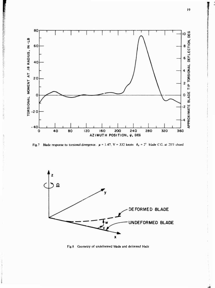
Typical results are shown In Figures (6) and (7). The nature of these results suggests that classical methods of blade flutter and divergence analysis, carried over from fixed wing practice, should be replaced by numerical solution of the blade equations of motion Including not only the conventional harmonic excitation forces, but also the nonlinear effects of reverse flow, variable Inflow, dynamic stall, and compressibility.
Classical flutter is a highly periodic self-excited motion; rotor blade motion at high advance ratio is largely due to external excitation. The actual level of blade motion is the important criterion, as seen in the present results, which demonstrate not a stability boundary, but a blade stress level boundar-' due to the excited motion. Even the "classical flutter" case exhibits the effects of first harmonic excitation, while the "torslonal divergence" case is the blade response to the lift acting at the blade three- quarter chord, and varying with the dynamic pressure over the reverse flow region.
At very high advance ratios, uncoupled flapping instability can occur due to negative aerodynamic damping and spring forces resulting from the periodic nature of the flow (Reference 12).
c. Finite Bending Effects
The preceding discussion has neglected the effect of steady state coning, collec- tive pitch, and elastic bending displacement of the blade. For a conventional articulated rotor, these effects are small. However, for certain hub geometries, the steady state displacements of significant modes are of fundamental importance and cannot be neglected. A detailed analysis of such effects is presented in Reference (2). For example, in the absence of a lag hinge, steady state flatwise bending displacement of the blade intro- duces destabilizing moments due to centrifugal force which In extreme cases lead to in- stability when the blade chordwise center of gravity coincides with, or is even ahead of the blade aerodynamic center. These destabilizing moments are largely attenuated by the incorporation of a lag hinge.

w
treatad by Young with a restrictive analytical approach (Reference 13). Modal equations of motion were obtained, but the numerical results were evaluated for a blade represented by a centrally-hinged, spring-restrained, equivalent model. Young concluded that the triggering mechanism of the flap-lag-type Instability Is the lag degree of freedom.
Hohenemser treated the same problem, using a somewhat unconventional numerical Integration scheme (Reference 1^). Due to the various approximations made In Reference 14, the results presented there are of n qualitative nature.
Consider the hlngeless bl".dL shown In the hub plane axis system of Figure (8). Following the analysis of Reference 15, the displacements v and w are exrvessed as
v/R - - Y1(x)h1(t) (1)
w/R - n1(x)g1(t) (2)
where r)Ax) Is the first normal mode shape of blade lapwlse bending, ana gAt) is the modal displacement. Similarly, yAx) Is the first normal mode shape for blade lagwlse bending, and h.(t) Is the modal displacement.
The nonlinear equation of motion for flapwlse bending Is snown In Reference 15 to be
V V^^P.g,;,.^ [p|ö-F2X0-F8;r(2Flüe-F11X0)h( +
F^öh, ♦ F|9 g.h.J (3)
I where M » -7- / mrj4- ii
1 "o
w first mode rotating flopping frequency Fl
»3 yl r /•!
to be
' 0 K
F8 = ^ i^di
X0 rotor inflow ratio referred to hub plane
(*) = d/di^/ ( )' = d/dx
The nonlinear equation of motion for lagwlse bending Is shown In Reference 15
*H< h*-^VV-^r L4 + «L7e-2LeX0)g|- (L^ÖXo+a^L^Jh,
(t)
Lie*|2 -Li9ö«. M
where
- 77 Imy. dx M ■I ^1
w. * rirst mode rotating lagging frequency
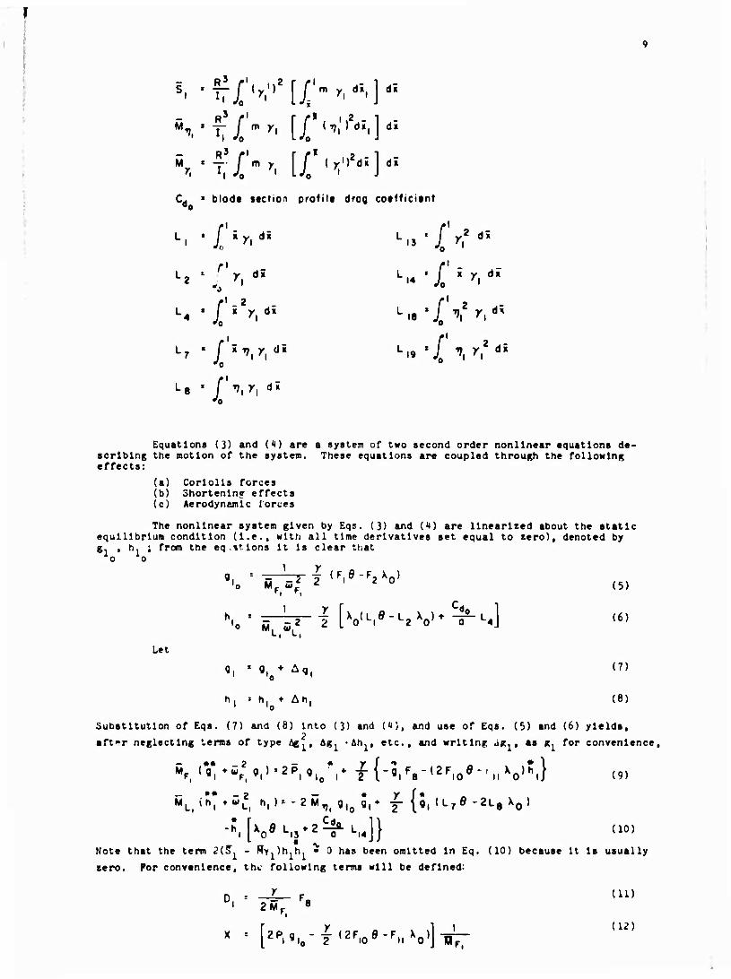
s, tTrjf{y.,,2[J>y'd5,]di
_ R /• r r ' 2 i M,•" "T" X " ''' iX ',|I'"IJ""
Cd > biode section profilt drag coefficient
L? = ''y, di LI4 'X " ^l d" r1
•4 ' f'*2***'* L.8'/ V y,d; ,l_2 L
■'o 'o
•'o 0
L8 ' / ^I^I d;
•'o
Equations (3) and (t) are a system of two second order nonlinear equations de- scribing the motion of the system. These equations are coupled through the following effects:
(a) Corlolls forces (b) Shortening effects (c) Aerodynamic iorces
The nonlinear system given by Eqs. (3) and (4) are linearized about the static equilibrium condition (I.e., with all time derivatives set equal to zero), denoted by g. , h. ; from the eq.»tlons It Is clear that
o o
"o Mr c; 2 l 2 0 (5)
h 'o M w 2 i [v-.o-'-aV^^] ">
Let
0, '■ fl, ♦ Aq (7) 'i0 -^i
h, » h, ♦• Ah, (8)
Substitution of Eqs. (7) and (6) Into (3) and (4), and use of Eqs. (5) and (6) yields, affr neglecting terms of type /^,, Ag, 'Ah., etc., and writing jg, , as g. for convenience.
(9)
Note that the term ?(?. - Ry )h h • 0 has been omitted In Eq. (10) because It Is usually
zero. For convenience, the following terms will be defined:
D, ■ -4- Fa (ID 1 2MF 8
(12) x " [2P.9.o-y,2F.oö-'rnxo»]-iör^
10
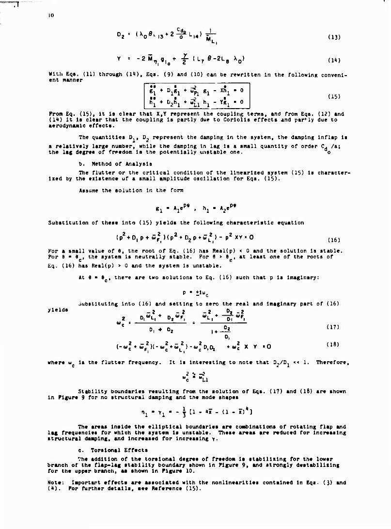
02= (X0^.3*2^ll'-|4)^- (l3j
-2i*V flu+ f (L7 e-2L8 X0) 'Vlo 2 lL7 a"^l-8 A0' (1*)
With Eqs. (11) through (l^), Eqs. (9) and (10) can be rewritten In the followlnR conveni- ent manner
K ♦ Di*i * ^i «i - ^i ■o
" * D2Ä1 * ^1 hl - Y*l ' 0 (15)
Prom Eq. (lb), It la clear that X,Y represent the coupling terms, and from Eqs. (12) and (14) it Is clear that the coupling Is partly due to Corlolls effects and partly due to aerodynamic effects.
The quantities D , D, represent the damping In the system, the damping inflap Is a relatively large number, while the damping In lag Is a small quantity of order C. /a; the lag degree of freedom Is the potentially unstable one. o
b. Method of Analysis The flutter or the critical condition of the linearized system (15) is character-
ized by the existence of a small amplitude oscillation for Eqs. (15).
Assume the solution in the form
g1 - A^P* . h1 - A2.P*
Substitution of these into (15) yields the following characteristic equation
(p2*D|p +wj )(p2*D2p*JL2) - p2 XY«0 (16)
For a small value of 6, the root of Eq. (16) has Real(p) < 0 and the solution is stable. For 6 ■ 6 , the system is neutrally stable. For 6 > 6 , at least one of the roots of Eq. (16) has Real(p) > 0 and the system is unstable.
At 6 ■ 8 , there are two solutions to Eq. (16) such that p is imaginary:
P " lluc
Substituting into (16) and setting to zero the real and imaginary part of (16) yi«ld" _2 _2 _2 0. -2
2 o, L, Oj r, L, oi I w.
0, (17) 0, ♦ 0, u_^ 0,
(-«J ♦ Jp2»-*»2*^,2)-«^,^ ♦«2 X Y «O {l8)
where w is the flutter frequency. It is interesting to note that D-./D. << 1. Therefore, c * i
2 \ -2 -c " "LI
Stability boundaries resulting from the solution of Eqs. (17) and (16) are shown in Figure 9 for no structural damping and the mode shapes
nl " Yl " " T Cl " "" " (1 ' i")*3
The areas Inside the elliptical boundaries are combinations of rotating flap and lag frequencies for which the system Is unstable. These areas are reduced for increasing structural damping, and Increased for increasing y.
c. Torsional Effects The addition of the torsional degree of freedom is stabilizing for the lower
branch of the flap-lag stability boundary shown In Figure 9, and strongly destabilizing for the upper branch, aa shown in Figure 10.
Note: Importart effects are associated with the nonlinearltles contained in Eqs- (3) and (4). For further details, see Reference (15).
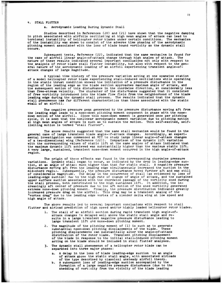
4. STALL FLUTTERa. Aerodynamic Loading During Dynamic StallStudies described In References (20) and (21) have shown that the negative damping
In pitch associated with airfoils oscillating at high mean angles of attack can lead to torsional Instability of helicopter rotor blades under certain conditions. The mechanism of the Instability was shown to consist of the adverse time phasing of the aerodynamic pitching moment associated with the loss of blade bound vortlclty as the dynamic stall occurs.
Subsequent tests, Reference (22), Indicated that the same mechanism Is found for the case of airfoil linear angle-of-attack change through high angles of attack. The nature of these results Indicated several Important conclusions not only with respect to the analysis of rotor blade stall flutter Instability, but also with respect to the gen
eral nature of the aerodynamic loading of an airfoil experiencing transient angle-of- attack changes of large magnitude.
A typical time history of the pressure variation acting at one spanwlse station of a model helicopter rotor blade experiencing stall-induced oscillations while operating In the static thrust condition showed the Initiation of a pressure disturbance In the region of the leading edge as the blade section approaches maximum angle of attack, and the subsequent motion of this disturbance In the chordwise direction, at considerably less than free-stream velocity. The character of the dlstu-bance suggested that It consisted of free vortlclty Introduced Into the blade flow flela from the neighborhood of the blade leading edge during the dynamic stall process. The results indicated that the dynamic stall phenomenon has far different characteristics than those associated with the static stall of an airfoil.
The negative pressure peak generated by the pressure disturbance moving aft from the leading edge leads to a nose-down pitching moment camponent In phase with the nose- down motion of the airfoil. Since this nose-down moment Is generated once per pitching cycle. It Is seen that the nonlinear aerodynamic moment variation due to pitching motion at high mean angles of attack Is such as to sustain the notion. This self-excited, self- limiting motion Is termed "stall flutter".
The above results suggested that the same stall mechanism would be found In the general case of large transient blade a.ngle-nf-attack changes. Accordingly, an experi
mental Investigation was commenced at MIT to study large linear angle-of-attack changes of a two-dimensional wing (Reference (22)). Comparison of the dynamic lift variation with the corresponding values of static lift at the same angles of attack Indicated that the maximum dynamic lift achieved was substantially higher than the maximum static lift. A very large, sustained, transient nose-down moment occurred In the high angle-of-attack region.
The origin of these effects was found In the corresponding chordwise pressure variations. Dynamic stall began to occur, as Indicated by the drop In leading-edge suc
tion, at an angle of attach much higher than that for static stall. A negative pressure disturbance moving aft from tne leading edge simultaneously increased the suction in the mid-chord reglo). Subsequently, the pressure disturbance moved further aft and was still of considerable magnitude. The delay In the occurrence of stall (as evidenced by loss of leading-edge suction) due to the high rate of cnange of angle of attack, and the sustained upper surface suction associated with tne chordwise passage of the vortlclty shed during tne stall process, both contributed to the high sustained lift. In addition, the In
creasingly aft center of pressure due to the aft motion of the shed vortlclty generated extreme nose-down pitcnlng moment. Finally, the pressure distribution Indicated greatly Increased pressure drag on the airfoil. This drag may be a transient analog of the "vortex drag" due to the leading edge vortex of a slender delta wing at low speed and high angle of attack.
The above results led to several Important conclusions with respect to stall flutter and airload prediction of high speed and/or highly loaded helicopter rotor blades.
1. The stall of an airfoil section during rapid transient high angle-of- attack changes is delayed well above the static stall angle and re
sults in a large transient negative pressure disturbance leading to large transient lift and nose-down pitching moment.
2. The magnitude of the pitching moment of (1) Is such as to generate substantial nose-down pitching displacements of the blade. These pitching displacements can substantially alter the angle-of-attack distribution of the rotor blade. Transient pitching displacement of the blade In response to the Initial stall-induced pitching moment acting on the blade should be Included In stall flutter analyses.
3. The dynamic stall phenomenon of a helicopter rotor blade can be separated into three major phases:
b.
A delay in the loss of blade leading-edge suction to an angle of attack above the static stall angle, with associated airloads of the type descrloed by classical unsteady airfoil theory.A subsequent loss of leading-edge suction accompanied by the formation of a large negative pressure disturbance (due to the shedding of vortlclty from the vicinity of the blade leading

i:
edge) which moves aft over the upper surface of the blade.Associated with this phase are high transient lift, drag, and nose-down pitching moment associated with the greatly altered pressure distribution on the airfoil,
c. Complete upper surface separation of the classic static type, characterized by low lift, high drag, and moderate nose-down pitching moment.
b. Method of AnalysisInvestigations of harmonically oscillating two-dimensional wings In forced motion,
for example. References (15), (16), (17), (18). (19), (20), and (21) have demonstrated that under stalled conditions the average damping In pitch over a cycle can become substantially negative and Is strongly dependent on the wing mean angle of attack, the reduced frequency of the harmonic motion, the oscillation amplitude, and the airfoil configuration and pitch- axis location. Reference (16) Indicated that the origin of the negative damping was aero
dynamic moment hysteresis, and that for certain mean angles of attack, reduced frequencies and amplitudes of oscillation, the mean damping In pitch was zero over a cycle, and that, under these conditions, a self-excited but ^elf-llmltlng one degree of freedom limit cycle oscillation of prescribed amplitude could occur. These results Indicate that potential theory unsteady aerodynamic predictions of two-dimensional airfoil pitch damping are pro
gressively less representative as the mean angle of attack approaches the static stalling ang.ie. Typical variation of the pitch damping with mean angle of attack Is shown In Figure (11). This figure represents an analytic synthesis of data presented In References (16), (17), and (20). In the referenced experiments, the amplitudes of the stable limit cycle oscillation were developed as functions of the initial angle of attack and reduced frequency. In the present analytic synthesis, an attempt was made to correct for differ
ences in rotation point and static stalling angles of the various data. This was followed by a calculation of equivalent viscous damping. The necessary balance of energy over a cycle of oscillation yielded a generalized equivalent viscous pitch damping function.This equivalent viscous damping function by the nature of the averaging process smooths out the higher frequency components of the destabilizing aerodynamic pitching moment. It Is Important to note that the Instantaneous values of negative damping vary about this mean value and can be substantially more negative near the stalling angle.
The extent of the stalled regions of a helicopter rotor and the possibilities for unstable pltchlng-torslonal oscillations are Illustrated In F. jure (12) which Illustrates a typical angle-of-attacx distribution In the high speed cruise condition. This distribu
tion Is based on a detailed calculation of the rotor velocity field, and Indicates an ex
tensive region of stall; the corresponding net Integrated pitch damping Is found to be negative over a significant range of azimuth angles. This Indicates the origin of a transiently unstable pltchlng-torslonal oscillation which will occur with a once per rotor revolution repetition rate. Since only a few cycles of torsional motion are possible be
fore the blade becomes unstalled, limit cycle motion is usually not achieved. However, substantial increases In blade torsional stress and pltc.h link loads are possible either by self-excitation or In response to external disturbances.
Experimental evidence of sucn unstable pltchlng-torslonal oscillations or rotor blade "stall flutter" Is abundant. The term "comfort stall" has been used to describe an almost asymptotic rise In cyclic pitch link loadings and related helicopter vibratory phenomena which occur wh-?n significant zones of blade stall are present. Some typical ex
perimental evidence of this asymptotic rise In cyclic pitch link loadings Is presented In Figure (13) in the form of a set of wave forms showing the tine variation of the torsional loading In a typical case.
In view of the experimentally derived damping function, the current Insight into the rotor stalling pattern, and this experimental evidence. It Is evident that the net pitch damping of the rotor blade can and often does become periodically negative In for
ward flight. Therefore, whenever combinations of thrust ratio and rotor advance ratio result In significant zones of blade stall, an unstable torsional oscillation may result.
The stability boundary can be approximated by considering the net aerodynamic pitch damping of the rotor blade control system fundamental pltchlng-torslon mode of os
cillation. Because of the complex angle-of-attacx distributions which occur In forward flight, this net damping function will vary widely with azimuth. It can be expected to exhibit a heavily damped condition In the region of blade advance, and can be expected to exhibit a negatively damped condition In the region of blade retreat. If large values of rotor thrust coefflclent-solldlty ratio and/or rotor advance ratio lead to significant zones of stalling. Inasmuch as the Instantaneous negative pitch damping can exceed the averages shown In Figure (11), a simple approximation of the stability boundary Is ob
tained by the condition that the motion will be transiently unstable if
wtiQhftd0¥trog«
J* c, <«o> dx s 0
where the reduced frequency Is based on the actual velocity at the reference radius of the retreating blade rather than on the mean velocity, l.e.;
h (X,*) .fi sin ^
In other words, the local blade element average damping ratio (depending on the

fl
local Initial angle of attack and local reduced frequency) la weighted by the square of the local fundamental mode amplitude to obtain the net pitch damping at each azimuth angle. If this weighted average damping becomes negative at any azimuth angle, the pltchlng-torslonal motion can be expected to become transiently unstable. If the range of azimuth angles over which the pitch damping Is negative Is broad enough to permit one or more cycles of a torsional oscillation, a marked Increase In cyclic control loading can be expected.
To Illustrate the application of this stability criterion, a calculation of the net damping function versus azimuth angle was carried out In Reference (20) for a severe rotor loading condition characterized by u • .17 and C.p/o • .111. The result of thiscalculation Is presented In dimensional form It. Figure (lit). It Is seen that the net pitch damping Is negative for the region bounded by the azimuth angles 225“ and 10“ (or 370“). Stall flutter would be expected to occur. Figure (13) presents torsional strain and pressure data for this flight condition which Is seen to support the theoretical pre
diction of stall flutter. The trace of absolute pressure transducer at the 80 percent radius station and 5 percent chord point Is Indicative of the loss of leading edge suction and accompanying pitching moment variation. It Is seen that the blade torsional response to this initially nose-down moment exhibits an unstable behavior in the region In which the net damping In pitch Is negative. In this case, the Instability is short-lived, lut especially pronounced, as evidenced by the peak In the pitch link load trace near the 330“ azimuth.
A more precise method of evaluating stall flutter effects has recently been de
veloped (References (23), (2U), (25), (26)). The equations of motion, e.g.. Subsection 2a, are solved numerically for the actual blade motion. Including the forcing aerodynamic terms due to blade dynamic stall.
The representation of blade dynamic stall Is based on the results of References (22) and (27), some of which are presented In Figure (15). The applicability of these two-dimensional results to the rotating blade Is demonstrated In Reference (28). It Is seen that under conditions of rapid transient, as opposed to oscillatory. blade angle-of- attack change, the maximum lift and torsional moment generated are proportional too^*^c/V, where (s) denotes the value at the Instant of dynamic stall, and are considerably larger In magnitude than those measured In tests of airfoils oscillating through the stall. In the latter case It Is believed that some degree of flow separation persists throughout the oscillatory cycle, leading to forces and moments that are lower than those found In the transient tests.
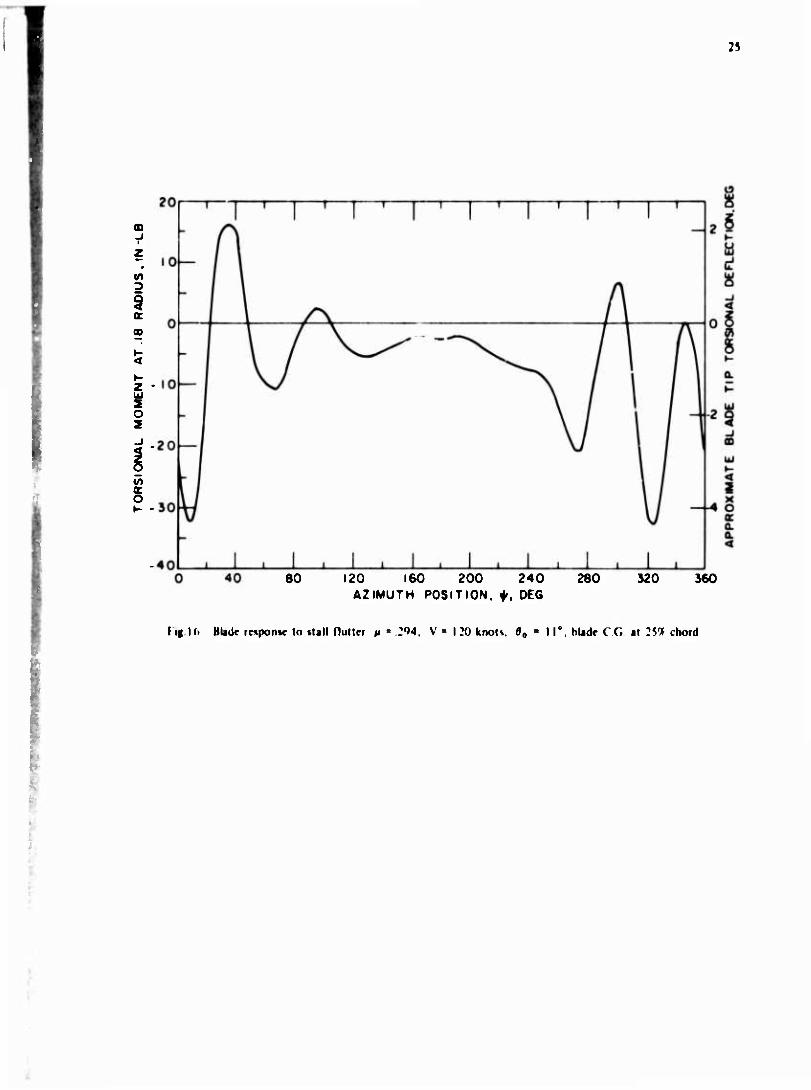
The three degrees of freedom considered In the analysis are rigid blade pitching about the feathering axis, rigid blade flapping about the zero offset flapping hinge, and blade first mode flatwise elastic bending. Variable Inflow and reverse flow are Included In the computation of blade forces and moments. The calculation of Inflow, aerodynamic loading, and blade motion Is performed Iteratively, using estimated steady-state initial values.
A typical result Is shown In Figure (16). The corresponding rotor angle-of- attack distribution Is shown In Figure (17). Note that the blade passes In and out of stall several times as a result of Its torsional response to the Initial dynamic stall.
c. Mearj of Alleviating Stall FlutterSeveral approaches to the design problem of postponing rotor blade stall flutter
are evident. The first Is the obvious one of avoiding significant regions of blade stall by Increasing rotor solidity beyond that dictated by ordinary performance considerations. This approach may Incur a performa.~>ce penalty. Excess solidity Increases rotor profile drag, resulting in a reduced rotor lift to effective drag ratio at the design point, with an attendant loss In the helicopter's range and maximum speed capability. A second rp- proach Is to counteract the negative aerodynamic pitch damping with positive mechanical damplnr. The difficulty stems from t.he deformation pattern associated with the funda
mental torsion mode. Generally, this mode Is twisting motion In addition to rigid body pitching against the effective tcrslonal spring of the helicopter control system. In this case, a dashpot In parallel with the control system Is relatively Ineffective, and in
ternal torsional damping becomes necessary; this is slight In conventional sietal rotor blade structures. On the other hand, the use of a glass fiber-resin matrix structure could be expected to dissipate considerable energy In torsion due to Its vlsco-elastlc damping which varies with the rate of sheer strain.
The most appealing approach, wlti the least performance penalty and design com
plication Is to reduce the extent of the stalled zones by departing from the typical con
temporary blade airfoil section, and employing sections having high dynamic stall angles. Sections having an appreciable amount of leading edge camber have favorable dynamic stall characteristics (References (29) and (30)).
REFERENCES
1, Loewy, R.O., "Review of Rotary Wing V/STOL Dynamic and Aeroelastlc Problems" Journal of the American Helicopter Society. 1*. 3, July 1969.
2. Miller, R.H., and Ellis, C.W., "Blade Vibration and Flutter", Journal of the American Helicopter Society. 1, 3, July 1956. - - - - - - - - -
3* Blspllnghoff, R.L., Ashley, H., and Halfman, R.L., Aeroelastlclty. Addison Wesley,
<t. Greenberg, J.r.,, Airfoil In Sinusoidal Motion In a Pulsating Stream. National Advisory Committee for Aeronautics Technical iJote 1326, June 19<t7.
5. Miller, R.H., "Unsteady Air Loads on Helicopter Rotor Blades". Journal of theRoyal Aeronautical Society, 68, 6AC, April 196A. - - - - - - - - -
6. Miller, R.H., AeroelastIc Problems of VTOL Aircraft. Motes for a Special Summer Program, Aeroelastlc and Structures Research Laboratory, M.I.T., June 1958.
7. Loewy, R.O., "A Two-Dimensional Approximation to the Unsteady Aerodynamics of Rotary Wings", Journal of the Aeronautical Sciences. 2A, 2, February 1957.
8. Zvara, J., The Aeroelastlc Stability of Helicopter Rotors In Hovering Flight. Aeroelastlc and Structures Res :arch Laboratory , M.I.T., Technical Report 61-1, September 1956.
9. Daughaday, H., DuWaldt, P., and Oates, C., "Investigation of Helicopter BladeFlutter and Load Amplification Problems", Journal of the American Hellcooter Society. 2, 3, July 1957. - - - - - - - - - - - - - - - - - - - - - -
10. Sibley, J.D., and Jones, C.H., "Some Design Aspects of Tandem Rotor Helicopters", Journal of the Helicopter Association of Great Britain. 13. 5, October 1959.
11. Ham, N.D., and Johnson, W., "Comparison of Dynamically Scaled Model Rotor Test Data with Step-by-Step Calculations of Rotor Blade Motion", Paper No. 3A1A,American Helicopter Society 25th Annual National Forum. May 1969.
12. Perisho, C.H., "Analysis of the Stability of a Flexible Helicopter Blade at High Advance Ratio", Journal of the American Helicopter Society. A, 2, April 1959.
13. Young, M.I., "A Theory of Rotor Blade Motion Stability In Powered Flight", Journal of the American helicopter Society. 9, 3, July 1964.
14. Hohenenser, K.H., and Heaton, P.W., "Aeroelastlc Instability of Torslonally Rigid Helicopter Blades", Journal of the AHS. 12, 2, April 1967.
15. Friedmann, P., and Tong, P., Dynamic Nonlinear Elastic Stability of Helicopter Rotor Blades In Hovered In forward Plight. M.t.T. Aeroelastlc and Structures Research Laboratory, AShL Tr 166-3, May 1972.
16. Halfman, R.L. et. al., Evaluation of Hlgh-Angle-of-Attaeic Aerodynamic Derivative Data and Stall-Flutter Prediction technlquesT NACA TN2533. 1951.
17. Rainey, A.G., Preliminary Study of .^.ome Factors which Affect the Stall-Flutter Characterlstlc~of Thin wings. NACA TN36^j. l956.
18. Rainey, A.G., Measurement of Aerodynamic Forces for Various Mean Angles of Attack on an Airfoil Oscillating In Pitch, etc., with Emphasis on bamping In the Stall. jIaCA TR1305, 1957.
19. Bratt, J.B., and Wight, K.C., The Effect of Mean Incidence. Amplitude of Oscilla
tion, Profile and Aspect Ratio on Pitching Moment Derivatives. Aeronautical Research Committee R. and M. Ho. 2064, 1945.
20. Ham, N.D., and Young, M.I., "Torsional Oscillation of Helicopter Blades Due to Stall", Journal of Aircraft. 3, May-June 1966.
21. Carta, F.O., "An Analysis of the Stall Flutter Instability of Helicopter Rotor Blades", Journal of the American Helicopter Society. 12. 4, October 1967.
22. Ham, N.D., and Garellcii, M.S., "Dynamic Stall Considerations In Helicopter Rotors", Journal of the American Helicopter Society, Iji, 2, April 1968.
23. Johnson, W., "The Effect of Dynamic Stall on the Response and Airloading of Heli
copter Rotor Blades", Journal of the American Helicopter Society. l£, 2, April 1969.24. Gross, D.W., and Harris, F.D., "Prediction of Inflight Stalled Airloads from
Oscillating Airfoil Data", Paper No. 322. American Helicopter Society 25th Annual National Forum. May 1969. - - - - - - - -
25. Tarzanln, F.J., "Prediction of Control Loads Due to Blade Stall", Journal of the American Helicopter Society. 17. 2, April 1972.
26. Carta, F.O., Commerford, G.L., and Carlson, R.G., "Determination of Airfoil and Rotor Blade Dynamic Stall Response", Preprint No. 613, American Helicopter Society 28th Annual National Forum. May 1972.
f]
M
J7. Ham, JJ.D., "Aerodynamic Loa^ln« on a Two-Dimensional Airfoil Durlnr Dynamic "tall", AIAA Journal. 0, 10, October 1968.
McCroskey, W.J., and Fisher, P.K., "Detailed Aerodynamic Measurements on a Model Rotor In the Blade Stall Regime", Journal of the American Helicopter Society. U, 1, January 197«;. ~ ' ~'~ ' " ~
Lllva, J., and Davenport, F.J., "Dynamic Stall of Airfoil Sections for High-Speed Rotors", Journal of the American Helicopter Society. 1^, 2, April 1969.
30. Benson, R.O., Dadone, L.U,, Oormont, R.E., and Hohler, O.R., "Influence of Airfoils on Stall Flutter Boundaries of Articulated Helicopter Rotors". Preprint No. b21, American Helicopter Society 29th Annual National Forum. May 1972.
2b
2 9

If.
C3ß dT(s)
sß2dm
I ig I Blade bending geometry
dT(r) dMA« (r )
////////////////////
t ig 2 Blade torsional geometry

•
COMPLETE SHED AND TRAILING WAKE SHED WAKE ONLY NEAR SHED WAKE ONLY
Fig.3 Effect of advance ratio ft on unsteady aerodynamic effects
7.5
2.5
T
FLUTTER BOUNDARIES ^=0 DIVERGENCE BOUNDARIES /i=0
C'U) = ! XA = 0
CG, % CHORD AFT OF FEATHERING AXIS
—— 11 ——
17
Fig.4 Flutter and divergence boundaries for flapping rotor blade

18
7.5
w.
ß
2.5
C'U) = I C'Ck), Ref. 8 —O- i/2 = 2.5
xA = 0
2.5 5 7.5 10 CG. - % CHORD AFT OF ELASTIC AXIS
Fig.5 Flutter boundaries in hovering
40 80 120 160 20C 24Ü AZIMUTH POSITION, ^, DEG
280 320 360
Fig.6 Blade response to classical flutter M =.68, V = 284 knots, e0 = 4° blade CG. at 30% chord
19
40 80 120 160 200 240 280 AZIMUTH POSITION, ^, DE6
320 360
Fig.7 Blade response to torsional divergence, n = 1.47, V = 332 knots 0P = 2° blade CG. at 257c chord
DEFORMED BLADE
UNDEFORMED BLADE
Fig.8 Geometry of undeformed blade and deformed blade

20
1.6 —
1.5 —
1.4 —
1.3
1.2 —
13
>- o z UJ
o UJ (T LL
O
Ö z UJ en
<
E 1.0 <
o DC
0.8
1 1 1 1 1
\ \ \ i
-
-
l / v.i75 / y
1 1 1 1 / / / /
/
-
/? // - i v y / -
V // —
- 1 ^-^ / y = io
-
/ cdo = o.oi \ / a = 27r
—
- \ / a = 0.05 -
DENOTES REGION OF UNSTABLE LIMIT CYCLES ncMm-ce ocnrkKi r^c O-TAOI C
1
-
1
Lir ■ CYCLES
, 1 i
0.9
1.0 I.I 1.2 1.3 1.4 1.5 ROTATING FLAPWISE BENDING FREQUENCY äJp,
Fig.9 Stability boundaries for various values of 0C

21
i.
0.3 o
CD
O z »-
UJ </) x 0.2 p
UJ Q
3 OQ 0.1
<
cr o
CüFI « 1.175 ; CüL| = 1.283
y = 10. o- = 0.05
100 80 60 40 20 C N0N-ROTATING T0RSI0NAL FREQUENCY äi0
Fig. 10 Effect of torsional degree of freedom on flap-lag type of instability
CD
Is
<D
CM
I O
CO z ÜJ S o z o z
1.2
1.0
0.8
-1^ 0.6
0.4
. 0.2
0
-0.2
-0.4
-0.6
-0.8
- 1.0
-1.2
•1.4 -
1.6 -
■1.8
1 1 1 1 POSITIVE DAMPING LIMIT FROM POTENTIAL THEORY
0012 AIRFOIL xA = 0
10 RECIPROCAL OF REDUCED FREQUENCY -jj-
Fig.l I Approximation for generalized pitch damping

^ « 180'
«^270 ^=90°
^ = 0C
I ig,I 2 Theoretical angle of attack distribution with non-uniform downwash: Vertol inodel CH-47A front rotor
V = 140 kts; forward CG. position, gross weight = 27.500 lbs.

cT/ a .III
n a .17
ABSOLUTE PRESSURE TRANSDUCER LOCATED AT 5% CHORD
CO% RADIUS
PITCH LINK LOAD
TORSION STRAIN AT 13% RADIUS
TORSION STRAIN AT 46% RADIUS
TORSION STRAIN AT 69% RADIUS
TORSION STRAIN AT 90% RADIUS
LEADING EDGE SUCTION M
ty 60 120 ISO 240 300 360 60
h'ig.13 Airload and strain character of stall flutter

Jj 600
a i
X a >
i •: o
400
?00
200
I I 1 1 I
A /^ ¥-••
■
1
/ \ V
i 1 1 v 1 1 50 100 if>0 ?00
A/iMUTM ANGLE ^ ?50 300 J^o
i it- 1-4 Vi jfrotlvnjtnii Jjnipinn morm-ni tor liitiil.niunijl piuhrngloruon niixli-
o u. u
O o
2 x
5
o U. b. UJ O o »- z UJ
2 O 2
2
2
<J
5
._ ^m THEORY (REF ID r I
A EXPERIMENT (REF22) 3,0- _ EMPIRICAL
APPR0XIVATI0N^<- ' 's
^ " '%
__
2.01- _
1
i ^ tf --' X
i.oK X
X
oL 1 1 1 0.01 0.02 0.05
VELOCITY PARAMETER
0.01 002 0.03 0.04
0.04 0.05
0.2
0.6
-0.8
- 1.0
006
0.05 0.06 I 1
.. _______ 1 1 \ 1
X
X X ""Jv X
VS. v\ \
X
\\ — N\\ - -
— THEORr(f?EF27l \\N ( \
, X EXPERIMENT (REF?» ^
EMPIRICAL APPROXIMATION
\s
1 1 A 1 1
11»! 15 Maximum lit) and monieni cocfrictenl vmus ralr of dungi- of angle of aii.uk
25
z
Z
o 2
V)
80 120 160 200 240 280 320 360 AZIMUTH POSITION, f. OEG
I «16 Blade rnpontr to ilall flutter t» ■ 294. V ■ I 20 knots. 9, ■ 11°. Made CG at 257 chord

'(.
t • 0'
III! I HLiilc jii>:k- i>i jiijik JiMrihu(K>n lor cavr ol I igurc ; ■- JJ = T'M i = 0 — ■ 0 a

27
MANUAL ON AEROELAST1C1TY
VOLUME I INTRODUCTORY SURVEY
PART I STRUCTURAL ASPECTS
VOLUME II PART II AERODYNAMIC ASPECTS
VOLUME III PART III PREDICTION OF AEROELASTIC PHENOMENA
VOLUME IV PART IV EXPERIMENTAL METHODS
VOLUME V PART V FACTUAL INFORMATION ON FLUTTER CHARACTERISTICS
VOLUME VI PART VI COLLECTED TABLES AND GRAPHS
General Fdttor R.Mazet
CONTENTS OF VOLUME I
WJ.Duncjn Introductory Survey Aii».l959>
PART 1 - STRUCTURAL ASPECTS
CHAPIER 1 WS.Memp Analytical Repmentalion of the Dr'omMtion of Structure*
AI«.I9S9
CHAPIER 2 J.MHedfepelh Vibration Analy«» of Aircraft Aug.l9S9
CHAPIER 3 B.M.Fraeiji de Veubeke
Influence of Internal Damping on Aircraft Retonance
Nov. 1959
CHAPTER 4 ONERA Staff Theory of Ground Vibration Tcating May I960
CHAPTER 5 D.Benun The Influence of Powered Controb Aiif.l9S9
CHAPTER 6 D.LWoodcock Structural Non-Unearitics Apr. I960
CHAPTER? B.A.Boley Thcrmoeiatiicii) Feb. 196«
CHAPTER It
(A rrmmr of the original chapter by ft Lh^plinghoff. Aug. 1959)
H.N.Abramion Liquid PropeHanl Dynamict Dec. 196';
CONTENTS OF VOLUME II
PART II - AERODYNAMIC ASPECTS
CHAPTER I LLGamck General Introduction
CHAPTER 2 A.I. van der Vooren Two-Oimet» <onal Unearned Theory
June I960
July I960
* The dale« given itbl« to the tccepiancc of the nunutenpt by AGART

(HAPIIK I
(IHIMIK 4
(M\niK <
(IHI'IIK h
(MM'IIK 7
(HXiMIK S
(HXPIIK '»
(IIXPIIK 10
(MM'IIK II
D.I .MIIII.IIMS
D.I .Dmo
• .1 >jlkMI»
III um.iv
D.I .^(MHIUHK
lit >.kimiu-l
IIIMT DMIU-IIMOII.II SiilKonit throrv laii.D'fil
I hur DimriiMiMi.il Sunn llnoi\ Nnv.l'IM)
ilirci-DiinrnMiiii.il Sii|irrM>nit Ihniry Nov.I'M)
Imlui.il XrniilMi.MiiKv Nov.I4M>(I
MriMlrf-llmU rhc«»r\ Apr D'r.: KrtiMiin Nnv I'Wi?
Niin-Si.iiiiMi.in lln-or» iif AirdiiA nl linilr IhKkiKA\ in ImiMiijHrsMlik- I l«»<* Dei. I''(«(l
lliitkiic\s ami Houmlarv-ljvrr Iffrtl« Mjr.lW M.I.I irul.ilil .in.I
II.XshkN ' I niiMnn ni ih, urigiiial i iMf'tci l<\ II. h/i/n and ti.Airljrtiin, Km.lVtiO)
W.I .X.Xumi
I'.K.(.1IMII
Hit'< <iiii|i.iris<in öl lliri>r\ .nul i «(N'tmuMil M.i\ \'>t<l
(or (>M ill.iliii)( Mings
i III|HIII.II Valuo nl l>m»ali»rv M..r.l'>(.
P\KI III I'Ki
(HXI'liK I
< H\P1I K :
( II MM I K «
< MM'IIK 4
Supplcntrnl In < MMMI K 4
( MM'II K 5
(H\niK h
( MM'II K '
Supptrmrnl I» (lUntR 7
OIAPIIK h
«MM'IIK •»
(IIXPIIK 10
(OMIVIS Ol VOLIMI III
DKIIOSOI MROILXSIK PHI-SOMFNA
I .d.Hr.utlKnl
I W.DuilltKll
I .W.Dk.KtKh
I .»..Hi.uilKnl
ll.( i.Kuwncr
l.( \.l«.lll|u. k JIUI
l.l.Sihk-ll
\.l. \.in Ji r XcHircn
\.( .B.I uni!
D.J.Jtihns
• l.l j/cnncv
W.II.KivJ
S.D.II..III
Vn InlriNliit linn lu ihr I'ritlh lion of \CTi»rlj%lii Phrnomrna I i-b.!''(.' KrtiMon Scp T'd"
DiM-rirnuc .nul Krl.ilfil Sl.ilit N<i\ l'»(,»
Xorm-I.islu Phrnomrna
Low of ( onirol Aii|[.i<'(i4
i lullrr ami Rrsptmsr CakublHim in PraclKr Apr. l'»r.?
Ko*isioil Scp.l,>f>7
I lulli-r ( JUIII.IIIOIIS .IS XIIIOIIIJIU
PriKTNsr» \(>v. I ''»i^
Duvnosis ami Curr of F> lirr Iroublrs Apr.l''(>2
(fiicrjl Dynamic SlalnliU of Sv%lrms Nov.|l)6l with Man* l)rfrrr\ «f Krmlom
\ Summary of Ihr Thrurirs and F \prf imrnls on Panel I In Her lch.l'>(>!
\ Panrl ilulict Roir« May D^*'
llu- Lffrcl of Slrui-lural Drlnrmalion on Ihr Hrhatiour in Mrjtht of a Smo-Conlrol in VSVKUIIIIII wilh an Aulomalic Pilot July \'>i<x
Proprllrr-Roior Vshirl Hullrr Si-p.i'JhT
HrlKopirr Bladr > lultrr Scp.1%7

?*
' ONTENTS OF VOLUMt IV
PART IV tXfKRIMFNTAL MFTHOOS
CHArTER 1 DJ.Marlm .nut l.ljulrn
MrMurrmrnl o( Sinu lural Influrncr Coerndmta (kl I9hl
CHAPTER 2 K.C Urwi» jml D.I .WnOiy
Cfrnund KcvMiamc Telling Dec I'X.I
CHAPTER .1 M.(iau/) MraMirnnml of Inertia and Structural t)ampiiig
loh.l'Xil
CHAPTER 4 J.C.HJII 1 «priinirnlal Trchniqun for the MraMirrmrnl of Pown Control Imprdancr June 1964
CHAPTER 5 J.H.Hrjll Wind Tunnel Trchniqun for Ihr MraMirrmrnl of Ouillatory l>rnvativr\ Jan.l9M
CHAPTER 6 ( .Scnilon and N.( .1 ainbourni-
Similarity RM|uircmeni» for Klullcr Model Tnling Nov. 1 <>(.()
CHAPTER 7 I .S.WjNMrrmjn ,iiul W.J.Mykylow
Model Contlruction Jan.l()M
CHAPTER H L.S.Waucnnan and WJ.Mykylow
Wind Tunnrl Klullrr Teiti Jan.l'X.)
CHAPTER 9 W.(i.M<>l>nciix Rocket Sled. Ground-Launched Rocket and Free-Falling Bomb Facilities Jan.l'»«.!
CHAPTER 10 M.O.W.Wolfe and W.T.Kirkhy
Right Flutter Tests Dec! 9M
CONTENTS OF VOLUME V
PART V - FACTUAL INFORMATION ON FLUTTER CHARACTERISTICS
CHAPTER I K.A.hou Divergence and Reversal of Control
CHAPTER 2 D.R.Gaukroger Wing Flutter
CHAPTER ^ A.A.Regier Flutter of Control Surfaces and Tabs
CHAPTER 4 A.D.VSmitli Flutter of Powered Controls and of All-Moving Tailplanes
CHAPTER 5 N.( .Lambourne Flutter in One Degree of Freedom Revision
CHAPIER 6 W.G.Molyneux Approximate Formulae for Flutter Prediction
Feb. 1960
Feb. 1960
Feb. i960
Apr. I960
Aug. I960 Feb. 196«
Apr.|9(,0
CC VTINTS OF VOLUME VI
PART Vi - COLLECTED TABLES AND GRAPHS
A.l. van der Vooren The Theodorsen Circulation Function. Aerodynamic Coefficients Jan. 1964
{cunfnueJ]
1(1
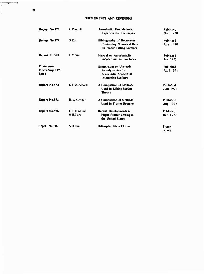
SUPPLEMENTS AND REVISIONS
Rrporl No 57J (; l'u/zoli
Rrpurl No.574 R.Dal
Report No 578
Conferrncf Procvrding» CFSO Part I
Report No 596
I (Pike
Report No 5HJ D.LWoodcock
Report No 592 MCKüssmr
E.F.Batrd and WB.Gark
Arrtwlaslic Test Methods. Experimental Technique«
Uibliography of Documents Containing Numerical Data on Planar Lifting Surfaces
Manual on Aeroelasticity Subject and Author Index
Sympisium on Unsteady Ar, odynamici for Acroelastic Analysis of Interfering Surfaces
A Comparison of Methods Used in Lifting Surface Theory
A Comparison of Methods Used in Flutter Research
Recent Developments in Flight Flutter Testing in the United States
Published Dec. 1970
Published Aug. 1970
Published Jan. 1971
Published April 1971
Published June 1971
Published Aug. 1972
Published Dec. 1972
Report No 607 N.D.Ham Helicopter Bbde Flutter Present report