actwin tutorial 1(118) actwin tutorial - stesag · actwin tutorial this tutorial will ... ladder...
TRANSCRIPT

ActWin Tutorial 1(118)
Copyright © Actwin AB 2001 - 2005 Tutorial version 4.2.0 ActWin version 3.5+
ActWin Tutorial This tutorial will show how to use the most important parts of ActWin through ”walking around” in the menus and creating a small project. (It will therefore not show the shortest way of building a project) Table of contents: Start ActWin .............................................................................................................................4
Design of Window: ............................................................................................................................................. 5 The toolbar include this functions....................................................................................................................... 5 Hardware configuration: ..................................................................................................................................... 6 Allocate Known symbols (e.g. Inputs and Outputs) ........................................................................................... 8
Ladder editing grid mode:.........................................................................................................9 Grid area ........................................................................................................................................................... 10 Enable/disable Ladder editor grid mode. .......................................................................................................... 10 Symbol /address handling: ................................................................................................................................ 11 Select an existing symbol:................................................................................................................................. 12 Create a new symbol: ........................................................................................................................................ 12 Select an address type for the symbol: .............................................................................................................. 12 Select the address number:................................................................................................................................ 12 Using addresses directly: .................................................................................................................................. 12 Make a serial connection: ................................................................................................................................. 13 Ladder editing without symbols:....................................................................................................................... 13 Inverted contact................................................................................................................................................. 14 To make a parallel connection: ......................................................................................................................... 14 To insert a parallel connection: ......................................................................................................................... 14 To connect a contact in series: .......................................................................................................................... 15 To insert a contact in series:.............................................................................................................................. 15 To Delete contact: ............................................................................................................................................. 15 Create a coil: ..................................................................................................................................................... 16 Create a parallel coil: ........................................................................................................................................ 16 Give or change a symbol to (allocate) contacts and coils. ................................................................................ 17 To write a rung comment: ................................................................................................................................. 18 To start a second rung:...................................................................................................................................... 18
Make an H PLC specific Compare box: .................................................................................19 Make an arithmetic box (Code box): ......................................................................................20 Edit the content of an arithmetic box: .....................................................................................22
Write a Comment in a Code box............................................................................................................... 22 Make an H PLC specific Timer delay. ....................................................................................23
To change the Timer Preset value..................................................................................................................... 24 Create an H PLC specific Counter up. ...................................................................................25
Clear current value in a Counter. ...................................................................................................................... 26 To change the Counter preset value. ................................................................................................................. 27
User Library............................................................................................................................28 Included User Library files. .............................................................................................................................. 28
Structure your program by using Section Comments.............................................................30 Print the project ......................................................................................................................31 Export the content of the symbol window...............................................................................31
Test the printout with a preview: ...................................................................................................................... 32 Paper Printout.................................................................................................................................................... 33 Communication settings.................................................................................................................................... 34 Network address................................................................................................................................................ 34
LUMP address: ............................................................................................................................................. 34 Station numbers: ........................................................................................................................................... 34
To change settings............................................................................................................................................. 35 Programming mode........................................................................................................................................... 35 Ladder editor grid mode.................................................................................................................................... 35

ActWin Tutorial 2(118)
Copyright © Actwin AB 2001 - 2005 Tutorial version 4.2.0 ActWin version 3.5+
Auto Popup Properties ...................................................................................................................................... 35 Autosave. .................................................................................................................................................. 35 Automatic generation av Tag data base for import to Exor Designer....................................................... 35 High contrast mode. .................................................................................................................................. 36
Cut and Past /Move rungs and comments .............................................................................37 Search for addresses:................................................................................................................................. 38
Move addresses .....................................................................................................................38 On-Line Programming ............................................................................................................39 Monitor Windows....................................................................................................................40 On-Line Change: ....................................................................................................................41 Data memory tables ...............................................................................................................42 Export from Data Memory ......................................................................................................43 Import to Data Memory...........................................................................................................43 Change driver on an existing project......................................................................................44
Nano: NANOH.DLL ........................................................................................................................... 44 Help ........................................................................................................................................45 Save .......................................................................................................................................45 SFC programming ..................................................................................................................46
Alternative branch:.................................................................................................................................... 48 Parallel branch: ......................................................................................................................................... 48
Action................................................................................................................................................................ 48 Ladder action: ........................................................................................................................................... 48 Symbol action: .......................................................................................................................................... 48
Transition .......................................................................................................................................................... 48 Ladder transition: ...................................................................................................................................... 48 Symbol transition: ..................................................................................................................................... 48
Start to get used to building a network ............................................................................................................. 49 Start a project .................................................................................................................................................... 52
Create Activity condition for the graph ........................................................................................................ 57 Print the project................................................................................................................................................. 60
FBD programming ..................................................................................................................61 How to connect the Functions........................................................................................................................... 64 Print................................................................................................................................................................... 69
IL programming ......................................................................................................................70 Syntax check ..................................................................................................................................................... 74 Copy and past in the program ........................................................................................................................... 75 On-Line and Monitoring ................................................................................................................................... 75 Print Out............................................................................................................................................................ 76
Appendix A: Ladder editing old mode. ...................................................................................77 Ladder editing buttons: ..................................................................................................................................... 77 Create a contact:................................................................................................................................................ 77 Symbol /address handling ................................................................................................................................. 78 Select an existing symbol.................................................................................................................................. 79 Create a new symbol ......................................................................................................................................... 79 Select an address type for the symbol ............................................................................................................... 79 Select the address number................................................................................................................................. 79 Using addresses directly.................................................................................................................................... 79 Make a serial connection................................................................................................................................... 80 Ladder editing without symbols........................................................................................................................ 80 To make a parallel connection .......................................................................................................................... 81 To insert a parallel connection .......................................................................................................................... 81 To connect a contact in series ........................................................................................................................... 82 To insert a contact in series............................................................................................................................... 82 To draw a vertical line ...................................................................................................................................... 82 To select one or more contacts.......................................................................................................................... 83 To Delete contacts............................................................................................................................................. 83 Create a coil ...................................................................................................................................................... 84 Create a parallel coil ......................................................................................................................................... 84 Give or change a symbol to (allocate) contacts and coils. ................................................................................ 84 To write a rung comment .................................................................................................................................. 86 To start a second rung ....................................................................................................................................... 86 The system library............................................................................................................................................. 87

ActWin Tutorial 3(118)
Copyright © Actwin AB 2001 - 2005 Tutorial version 4.2.0 ActWin version 3.5+
To make a compare box or to insert a F or FB: ................................................................................................ 87 To create a User defined Function (F) or Function Block (FB):....................................................................... 88 Create a Function Block.................................................................................................................................... 89
Appendix B: ActWin Macro.....................................................................................................92 How to create a Macro ...................................................................................................................................... 92
1. Define a new macro .................................................................................................................................. 96 2. Insert the macro code ................................................................................................................................ 97
How to use the macro in a project................................................................................................................... 108 Other examples: Macro for PID-loop: ............................................................................................................ 117 Macro for 1 PID (More extended macro) ...................................................................................................... 117

ActWin Tutorial 4(118)
Copyright © Actwin AB 2001 - 2005 Tutorial version 4.2.0 ActWin version 3.5+
Start ActWin
Open ActWin: You will get the following Window: Open an existing project, the latest project (in this case “Maxi_306.apg” or a new project. • Select ”Create new project” with the mouse. • Click on ”OK”
If a dialog appears prompting you to select target system: • Select Hitachi H-series from the list of
selectable target systems • Click OK If it’s stand “DEMO” after the driver, the driver is in DEMO mode.
A new window appears where you can select what PLC language you want to use: • LD (Ladder) • SFC (Sequential Flow Chart) • FBD (Functional Block diagram) • IL (Instruction List) In PLC specific mode only LD is available. In Mixed mode LD and SFC are available. All are available in IEC1131-3 mode. Select PLC Specific Mode and LD, press OK

ActWin Tutorial 5(118)
Copyright © Actwin AB 2001 - 2005 Tutorial version 4.2.0 ActWin version 3.5+
Design of Window: You will now get the following screen with three main Windows:
1. Programming Window (Where you write the program, function blocks etc.) 2. Project Window (Complete hardware and software configuration of the project) 3. Symbol window (Where all symbols like Inputs, Outputs etc. can be edited)
The toolbar include this functions It is divided into following groups:
1. File handling and printout. 2. Cut, paste, undo etc. 3. Zoom tools. 4. Ladder editing (Not available in “Ladder editor grid mode”) 5. Help buttons (Do not forget to use the help system) 6. On-Line and communication
1.
3.
2.
1 2 3 4 5 6

ActWin Tutorial 6(118)
Copyright © Actwin AB 2001 - 2005 Tutorial version 4.2.0 ActWin version 3.5+
Hardware configuration: Open the Hardware configuration to select the hardware to run the PLC program by clicking in the tree on ”HW Configuration”
This will open ten new items. They all symbolise the racks in the configuration. The first is the one containing the CPU. The other ones are the expansion racks. Start to click with the right mouse button
on the first rack. (Instead of right click you can double click) Select the ”Add Module” alternative. You will now get a list of all Groups and modules available. Select a suitable base from the list, e.g. EH-BS8A from the EH-150 Base group .
The item will change name to ”EH-BS8A” and a + will appear to show that we can fill this rack with modules.
Click on the rack item and open it. In this case 10 new folders will appear. They are representing the modules in the base. Double click with the left mouse button on the first module. Select the power supply module. E.g. EH-PSA and press OK.
ActWin Tutorial 7(118)
Copyright © Actwin AB 2001 - 2005 Tutorial version 4.2.0 ActWin version 3.5+
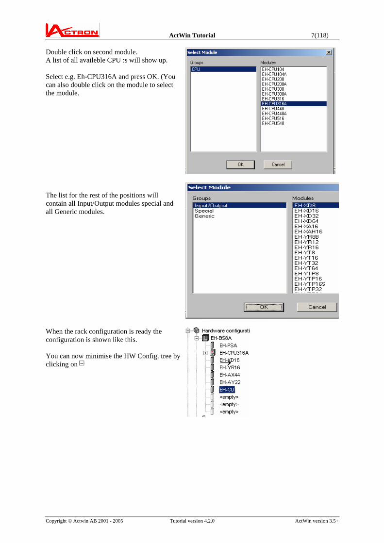
Double click on second module. A list of all availeble CPU :s will show up. Select e.g. Eh-CPU316A and press OK. (You can also double click on the module to select the module.
The list for the rest of the positions will contain all Input/Output modules special and all Generic modules.
When the rack configuration is ready the configuration is shown like this. You can now minimise the HW Config. tree by clicking on
→

ActWin Tutorial 8(118)
Copyright © Actwin AB 2001 - 2005 Tutorial version 4.2.0 ActWin version 3.5+
Allocate Known symbols (e.g. Inputs and Outputs) Right click on the CPU and select “Symbols/Addresses”.
You can type the symbol names on each address type in the CPU. (Some characters, e.g. Space are not allowed due the compatibility to the IEC standard, see help system) To enter the symbols in the I/O modules. You can import symbols from a CAD system or e.g. Word or Excel with Copy/Paste to the Name Column. Mark the first cell and press <Ctrl + V> use these buttons to go from one module to the next.

ActWin Tutorial 9(118)
Copyright © Actwin AB 2001 - 2005 Tutorial version 4.2.0 ActWin version 3.5+
Ladder editing grid mode: (For programming not in grid mode see section “Ladder editing old mode” There is a new and even much more effective way of Ladder editing in ActWin. It is a unique method based on a World patent owned by Actron. The basic idea in the patent is that object where you currently are working decides what you can do. It will present you all options and nothing else. You do not have to go and fetch any tools etc. You will save time and the risk of errors decreases Following main symbols occurs depending on where the cursor is: Description Main interactive symbol Detailed selection If you hold down the Left button a menu will show
the options. Select and release the button. The menu will also appear if you Right click
New rung or comment.
A left click will create a start contact.
New input object. Serial connection
New input object. Parallel connection above or beneath.
New Output object.

ActWin Tutorial 10(118)
Copyright © Actwin AB 2001 - 2005 Tutorial version 4.2.0 ActWin version 3.5+
Grid area If you press the Grid button you will see where the areas are and what symbol will occur in each area. It is not practical to work with the grid pattern on. So we recommend to turn it off again.
Enable/disable Ladder editor grid mode. Select “Tools-Act Win Settings” from the top menu. You can select to use the traditional Act Win ladder editor or the new one. When you test the method we recommend you to Disable Auto Popup Properties. (work without symbols) When you do real programming it is better to Enable this option.
When you start you will see two different cursors on the screen. The black one is for keyboard editing and the white one is for mouse editing.

ActWin Tutorial 11(118)
Copyright © Actwin AB 2001 - 2005 Tutorial version 4.2.0 ActWin version 3.5+
Create a contact: → Move the mouse approximately to the place where you want the contact. Click with left button.
Symbol /address handling: The symbol /address handling is probably the most important part in a PLC programming software. The reason for this is that a significant part of the programming time is spent here. Most programming errors are connected to usage of wrong addresses or double usage of addresses. ActWin gives a maximum comfort, guideline and control in the address allocation. In order to give an easy way to define or search for an address and the symbol name the following window will pop up automatically: Type the name of the symbol. When the symbol name does not exist you will always get a suggestion of the first free address. This makes allocation of new symbols very fast and you will avoid double use of addresses.
Here you can change to an inverted contact or an edge detection.

ActWin Tutorial 12(118)
Copyright © Actwin AB 2001 - 2005 Tutorial version 4.2.0 ActWin version 3.5+
When you type the symbol, all matching symbols will be shown.
Select an existing symbol: Instead of typing the entire symbol name, you can click in the list and select the symbol you want.
Create a new symbol: A new symbol does not have any match. If the suggested address is OK you can press Enter to create the symbol.
Select an address type for the symbol: If you want a special address, then click on the Memory address and select the type you want. You can also type the address with the number directly in the Memory address window.
Select the address number: The first available address of the type you suggested will be suggested. Accept or type the number you want and press Enter for OK.
You can also press the button to get the next available address.
Using addresses directly: Even though it is not recommended it can in some cases be comfortable to use the address directly. Just type the address. The symbol on that address will be used or if there is no symbol a new temporary symbol “__Y200” will be created. (All addresses have to have a symbol) Play a little with the symbol handling and get used to this method and you will realise the comfort.
The button allows you to define any number of symbols in a one operation. (see “arithmetic box” description for more details.)

ActWin Tutorial 13(118)
Copyright © Actwin AB 2001 - 2005 Tutorial version 4.2.0 ActWin version 3.5+
Make a serial connection: Repeat the procedure with the contact and insert the new contact on to the right side of the first one. As you can see, the editing field of the rung is marked (shown as deeper). This means that the rung is not ready and approved by ActWin. When it is completed the marking will disappear. Give the new contact a symbol name and an address: The new symbols will appear in the symbol window. This window will also inform about type, PLC address and the corresponding IEC1131 address Ladder editing without symbols: In order to make some different ladder editing without the symbol procedure for each contact, we can turn the symbol editing off. Make a new contact in series. But instead of giving a symbol name, disable ”Automatic pop up” and press OK. (You can also fetch this window, the Contact Properties, by right-clicking
on a contact) The contact will be drawn without symbol and address

ActWin Tutorial 14(118)
Copyright © Actwin AB 2001 - 2005 Tutorial version 4.2.0 ActWin version 3.5+
Inverted contact To make an inverted contact click and hold down mouse button, a menu will show the options. Select “Inverted contact”.(This can also be changed in the Contact Properties Window)
Note that the width of the ladder diagram is flexible. (the right power line moves rightwards) To make a parallel connection: Move the cursor down from the ladder line to indicate a parallel connection. A symbol for parallel connection appears.
Left click and all possible connection points for the parallel connect are marked with arrows.
Point and click at the correct connection point.
To insert a parallel connection: Make the same procedure as above inside the other connection.

ActWin Tutorial 15(118)
Copyright © Actwin AB 2001 - 2005 Tutorial version 4.2.0 ActWin version 3.5+
To connect a contact in series: Place the mouse arrow on the line where you want the contact. Click on the left mouse button.
To insert a contact in series: Place the mouse arrow on the line between the contacts where you want the contact. Click on the left mouse button.
To Delete contact: Click on the contact that should be deleted. The contact will be marked. Press Delete and the rung will be redrawn without the deleted contact.

ActWin Tutorial 16(118)
Copyright © Actwin AB 2001 - 2005 Tutorial version 4.2.0 ActWin version 3.5+
Create a coil: Place the curser at the right side of the ladder diagram. The cursor will change to a Coil symbol. Left click and the coil will be inserted.
Create a parallel coil: Place the cursor below the coil. The cursor will change to a parallel contact symbol. Right click and select Normal Coil or Set/Reset coil
Click on the arrow and the parallel coil will be completed.

ActWin Tutorial 17(118)
Copyright © Actwin AB 2001 - 2005 Tutorial version 4.2.0 ActWin version 3.5+
Give or change a symbol to (allocate) contacts and coils. Go to the contact or coil you want to allocate. Double Click (or click with the right mouse button
and select ”Properties”)
The Symbol selection and search window will appear. Type the new symbol name. (You are not limited to any length of the symbol. Just use a significant, but not too long symbol names out of practical reason. Note that blanks are not allowed.)
In this case, select Y for output.
If you have not decided the address number from the beginning, press ”Next free” and the software will suggest the first free unused output address.
Press OK and the coil is allocated. Continue with the same procedure or select already existing symbols from the list.

ActWin Tutorial 18(118)
Copyright © Actwin AB 2001 - 2005 Tutorial version 4.2.0 ActWin version 3.5+
Note that before the rung was completed it was shown on a “lower level” When the rung is completed and approved by ActWin the marking disappears.
To write a rung comment:
Place the cursor above or beneath an existing rung. A symbol for contact in a new rung appears. Right click and select “Comment” from the menu.
Click on the <Comment...> symbol. A window will open, where you can write the comment.
Press OK and the comment will be inserted in the ladder diagram.
To start a second rung: Place the cursor above or beneath an existing rung. A symbol for contact in a new rung appears. Click with the left mouse button and a contact in a new rung will be created.

ActWin Tutorial 19(118)
Copyright © Actwin AB 2001 - 2005 Tutorial version 4.2.0 ActWin version 3.5+
Make an H PLC specific Compare box: Treat the Compare box just like a contact but right click or press and hold down left button. Select Compare box from the menu.
Use the Monoculars to allocate the symbols or type a constant value.
Select the type of comparison.
Continue to build the network
ActWin Tutorial 20(118)
Copyright © Actwin AB 2001 - 2005 Tutorial version 4.2.0 ActWin version 3.5+
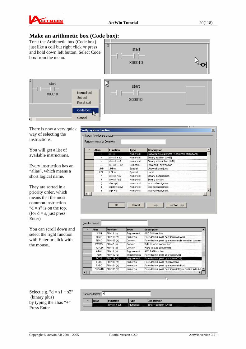
Make an arithmetic box (Code box): Treat the Arithmetic box (Code box) just like a coil but right click or press and hold down left button. Select Code box from the menu.
There is now a very quick way of selecting the instructions. You will get a list of available instructions. Every instruction has an “alias”, which means a short logical name. They are sorted in a priority order, which means that the most common instruction “d = s” is on the top. (for d = s, just press Enter) You can scroll down and select the right function with Enter or click with the mouse..
Select e.g. ”d = s1 + s2” (binary plus) by typing the alias “+” Press Enter

ActWin Tutorial 21(118)
Copyright © Actwin AB 2001 - 2005 Tutorial version 4.2.0 ActWin version 3.5+
Here you can define the symbols that are used in the instruction. The symbol type selectable. WORD is default here. Search or define the symbol like in the contact/coil dialog. Press <Tab> to enter the symbol and move to the next argument.
When the symbols and constants are defined, press OK
A window will pop up where all editing can be done. • Delete button will
delete a line. • Add Button will insert
a new line. You will get a list of all functions.
• Move buttons will move a line up or down
• Edit button will allow you to change an existing line.
Add another instruction and
press the button and the box is completed.

ActWin Tutorial 22(118)
Copyright © Actwin AB 2001 - 2005 Tutorial version 4.2.0 ActWin version 3.5+
Edit the content of an arithmetic box: Double click on the box
(or Right click and select ”Properties”). The edit box will open and allow you to continue editing.
Write a Comment in a Code box. The “Function format or Comment” window allows you to write any text.
This text will become a line comment in a Code box. Use the Move Up button to Move the Comment to the top.
Continue the coding through pressing the Add button (or press Insert)

ActWin Tutorial 23(118)
Copyright © Actwin AB 2001 - 2005 Tutorial version 4.2.0 ActWin version 3.5+
When you are ready, press the Close button.
Make an H PLC specific Timer delay. Create a coil. Give the new symbol a name and select address type TD from the address list. Press OK button.
In the Timer properties window enter Timer Preset time and select Time base. Press OK button
ActWin Tutorial 24(118)
Copyright © Actwin AB 2001 - 2005 Tutorial version 4.2.0 ActWin version 3.5+
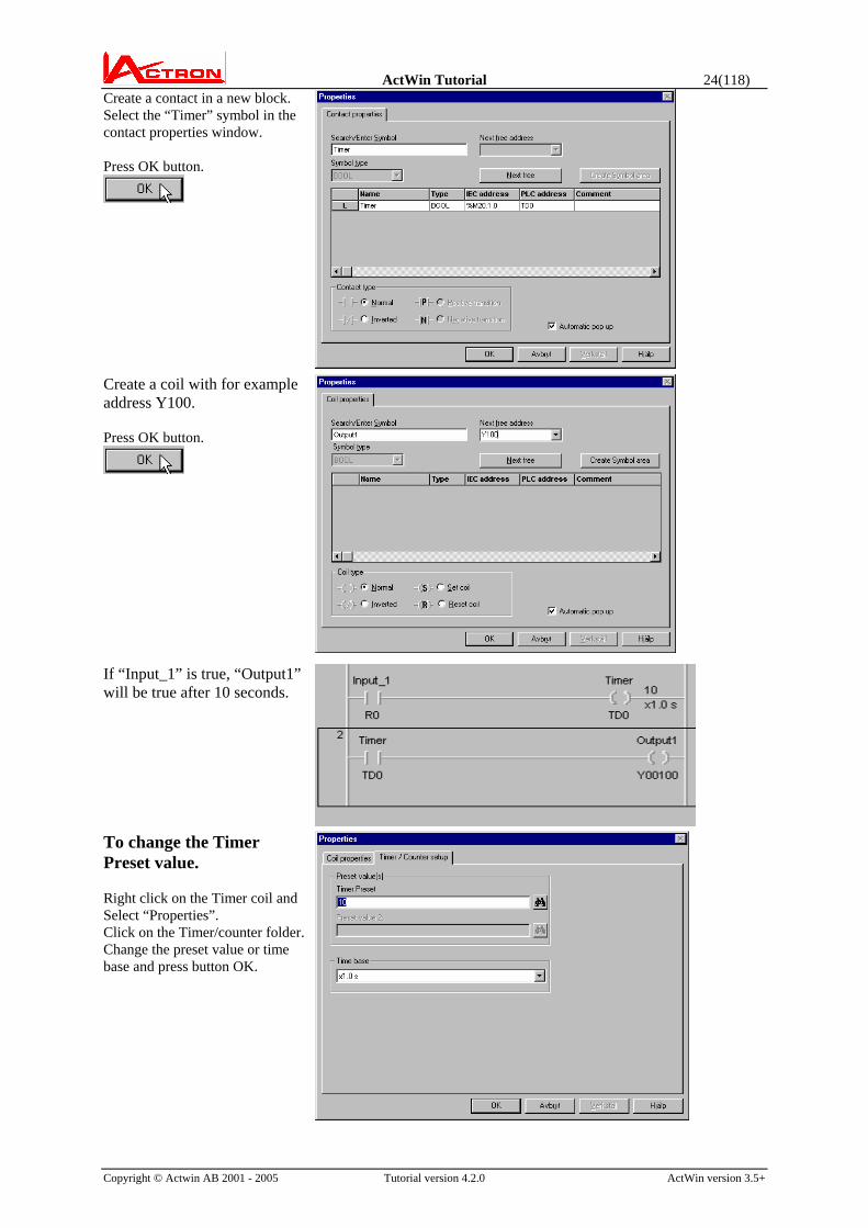
Create a contact in a new block. Select the “Timer” symbol in the contact properties window. Press OK button.
Create a coil with for example address Y100. Press OK button.
If “Input_1” is true, “Output1” will be true after 10 seconds. To change the Timer Preset value. Right click on the Timer coil and Select “Properties”. Click on the Timer/counter folder. Change the preset value or time base and press button OK.
ActWin Tutorial 25(118)
Copyright © Actwin AB 2001 - 2005 Tutorial version 4.2.0 ActWin version 3.5+
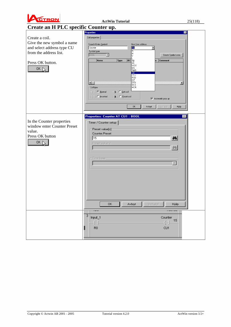
Create an H PLC specific Counter up. Create a coil. Give the new symbol a name and select address type CU from the address list. Press OK button.
In the Counter properties window enter Counter Preset value. Press OK button

ActWin Tutorial 26(118)
Copyright © Actwin AB 2001 - 2005 Tutorial version 4.2.0 ActWin version 3.5+
Create a contact in a new block. Select the “Counter” symbol in the contact properties window. Press OK button.
Create a coil with for example address Y101. Press OK button.
Clear current value in a Counter. Create a contact in a new block. Give the symbol a name and an address.. Press OK button.

ActWin Tutorial 27(118)
Copyright © Actwin AB 2001 - 2005 Tutorial version 4.2.0 ActWin version 3.5+
Create a coil and select the “Counter.CL” symbol in the coil properties window. Press OK button.
Every time “Input_1” goes high, the counter current value will increase with one. When “Clear counter” is high the Counter current value will be set to zero. To change the Counter preset value. Right click on the Counter coil and Select “Properties”. Click on the Timer/counter folder. Change the preset value and press button OK.
ActWin Tutorial 28(118)
Copyright © Actwin AB 2001 - 2005 Tutorial version 4.2.0 ActWin version 3.5+
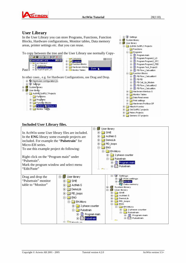
User Library In the User Library you can store Programs, Functions, Function Blocks, Hardware configurations, Monitor tables, Data memory areas, printer settings etc. that you can reuse. To copy between the tree and the User Library use normally Copy-
Past In other cases , e.g. for Hardware Configurations, use Drag and Drop.
Included User Library files. In ActWin some User library files are included. In the ENG library some example projects are included. For example the “Pulsetrain” for Micro-EH series. To use this example project do following: Right click on the “Program main” under “Pulsetrain”. Mark the program window and select menu “Edit/Paste”
Drag and drop the “Pulsetrain” monitor table to “Monitor”

ActWin Tutorial 29(118)
Copyright © Actwin AB 2001 - 2005 Tutorial version 4.2.0 ActWin version 3.5+
The ActWin window will look as follows.
ActWin Tutorial 30(118)
Copyright © Actwin AB 2001 - 2005 Tutorial version 4.2.0 ActWin version 3.5+
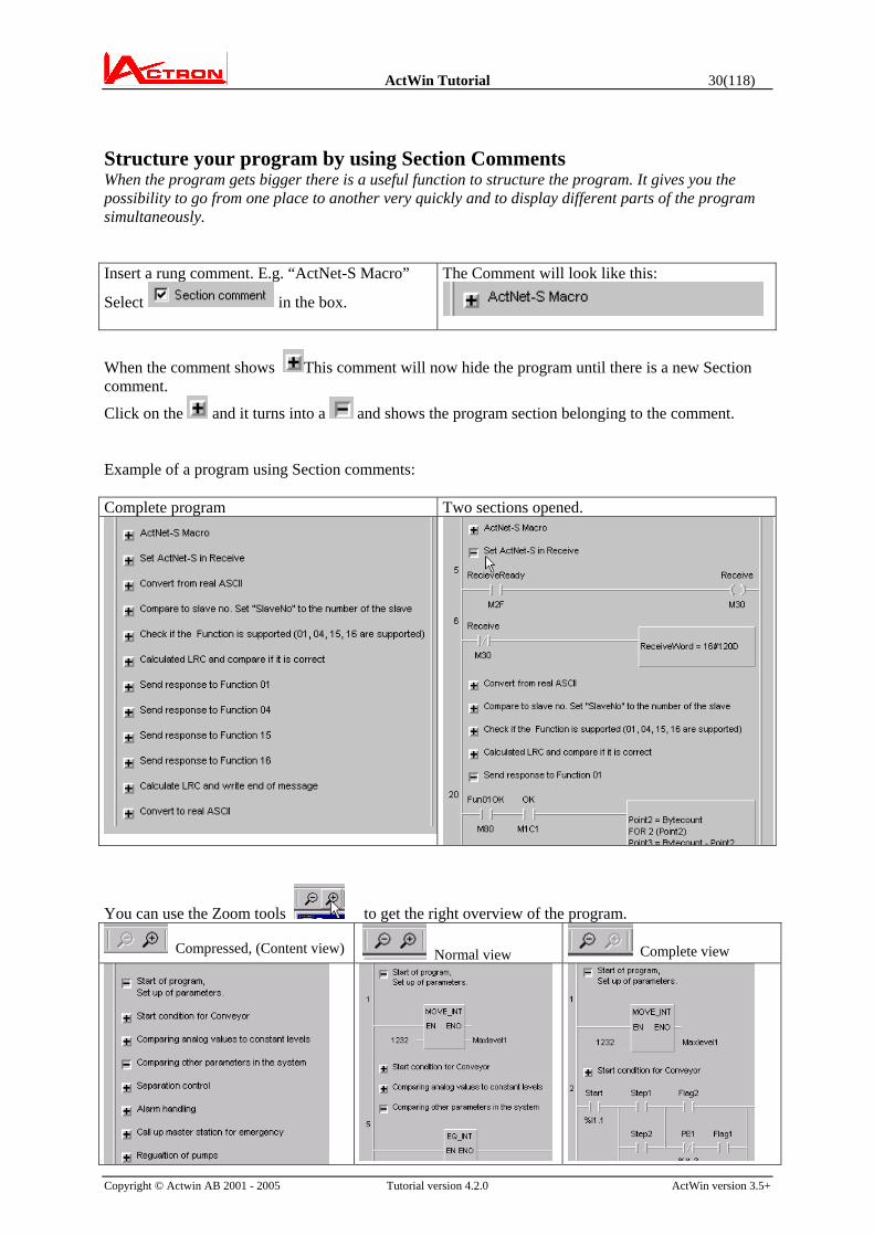
Structure your program by using Section Comments When the program gets bigger there is a useful function to structure the program. It gives you the possibility to go from one place to another very quickly and to display different parts of the program simultaneously. Insert a rung comment. E.g. “ActNet-S Macro”
Select in the box.
The Comment will look like this:
When the comment shows This comment will now hide the program until there is a new Section comment.
Click on the and it turns into a and shows the program section belonging to the comment. Example of a program using Section comments: Complete program Two sections opened.
You can use the Zoom tools to get the right overview of the program.
Compressed, (Content view) Normal view Complete view
ActWin Tutorial 31(118)
Copyright © Actwin AB 2001 - 2005 Tutorial version 4.2.0 ActWin version 3.5+
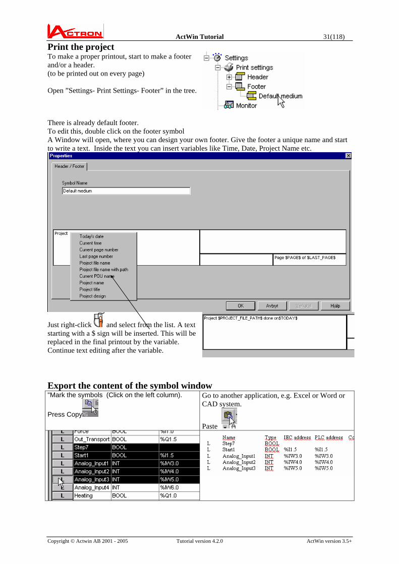
Print the project To make a proper printout, start to make a footer and/or a header. (to be printed out on every page) Open ”Settings- Print Settings- Footer” in the tree.
There is already default footer. To edit this, double click on the footer symbol
A Window will open, where you can design your own footer. Give the footer a unique name and start to write a text. Inside the text you can insert variables like Time, Date, Project Name etc.
Just right-click and select from the list. A text starting with a $ sign will be inserted. This will be replaced in the final printout by the variable. Continue text editing after the variable.
Export the content of the symbol window "Mark the symbols (Click on the left column).
Press Copy
Go to another application, e.g. Excel or Word or CAD system.
Paste

ActWin Tutorial 32(118)
Copyright © Actwin AB 2001 - 2005 Tutorial version 4.2.0 ActWin version 3.5+
Test the printout with a preview:
Click on the symbol for Preview. A page looking like the final paper print out will be shown on the screen. (Here the $ symbols are exchanged to the actual values.)

ActWin Tutorial 33(118)
Copyright © Actwin AB 2001 - 2005 Tutorial version 4.2.0 ActWin version 3.5+
Paper Printout
You can click on the symbol. Then you will get the complete printout. You can also select ”Print” in the File menu to get a more detailed printout command. If you select “Print all” you will get a selection list:
Select what printout you want and press Print. You can select to print out a part of a program. Mark it and then select the program in “Print all”

ActWin Tutorial 34(118)
Copyright © Actwin AB 2001 - 2005 Tutorial version 4.2.0 ActWin version 3.5+
Communication settings Go to menu “Tools-Driver settings” For RS232 communication you can select Comm. port and baud rate. For TCP/IP programming you can enter IP Address and port number. For more information see manual for the Ethernet card (For example EH-ETH)
Network address. From menu “Tools/Driver settings” Select the “Network address” folder. LUMP address: With this you can program/monitor different CPU´s in a LINK system. If you not using LINK connection, the value should be: FF, FF, 00, 00. Link: Link module number. Unit: Sub station number. Station numbers: For multidrop use. Enter station number on unit you should access.

ActWin Tutorial 35(118)
Copyright © Actwin AB 2001 - 2005 Tutorial version 4.2.0 ActWin version 3.5+
To change settings Go to ”Tools-ActWin Settings” Programming mode. We have started in the ”PLC specific” mode, which only allowed us to write programs compatible to traditional programming. If you want to continue in the IEC1131-3 programming, select ”IEC1131-3” or ”Mixed mode” Ladder editor grid mode To select “Ladder editor grid mode” select the “Enable Ladder editor grid mode” Auto Popup Properties Select “Enable Auto Popup Properties” for automatic popup of properties dialog . You can also find folders for Language, Display and Save.
Save folder. Autosave. For auto saving select the “Automatically save project” and set the interval Automatic generation av Tag data base for import to Exor Designer. For automatic generation of Tag data base file for import to Designer select the “Create Tag database when saving project”. The name of the file will be “projectname”.mdb

ActWin Tutorial 36(118)
Copyright © Actwin AB 2001 - 2005 Tutorial version 4.2.0 ActWin version 3.5+
High contrast mode. Under Display you can select a higher contrast display of the ladder diagram in stead of the modern relief type. This is practical on some computer screens. You can also edit the fonts sizes etc. in all screens.
If you select High contrast the screen will look like this:
ActWin Tutorial 37(118)
Copyright © Actwin AB 2001 - 2005 Tutorial version 4.2.0 ActWin version 3.5+
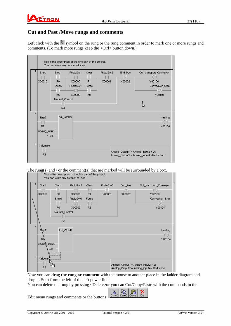
Cut and Past /Move rungs and comments Left click with the symbol on the rung or the rung comment in order to mark one or more rungs and comments. (To mark more rungs keep the <Ctrl> button down.)
The rung(s) and / or the comment(s) that are marked will be surrounded by a box.
Now you can drag the rung or comment with the mouse to another place in the ladder diagram and drop it. Start from the left of the left power line. You can delete the rung by pressing <Delete>or you can Cut/Copy/Paste with the commands in the
Edit menu rungs and comments or the buttons

ActWin Tutorial 38(118)
Copyright © Actwin AB 2001 - 2005 Tutorial version 4.2.0 ActWin version 3.5+
Search for addresses: Try the Find <Ctrl+F3> and Replace <Shift+Ctrl+F3> to find and replace symbols in the program.
A nice way to get a quick overview of the existence of addresses in the program and to go to the relevant place is to Right click on a symbol.
A list will appear informing about the rung numbers and e.g. if it is present as a contact or coil, if it is open or closed etc.
Click on the rung number you want to go to and you will move to that place in the program.
Let us change the rack configuration. We therefore have to change the addresses in the program. Inserted module Move addresses Click on the Move symbol in the symbol Window.
A “Move address” window will pop up. Define first and last address in every group to be moved and the first destination address. Press the Move button and symbols will change.
Continue until all address are moved.

ActWin Tutorial 39(118)
Copyright © Actwin AB 2001 - 2005 Tutorial version 4.2.0 ActWin version 3.5+
All I/O addresses in the list and in the ladder program will change.
On-Line Programming Communication / Transfer: 1 2 3 4 5 6 7 Following buttons are available: 1. RUN (Start the PLC) 2. Stop 3. Monitor. 4. Transfer the program to the PLC 5. Upload the program from the PLC 6. Go On-Line (First Compares PLC-PC) 7. Update program.
Active when program is edited On-Line
You can also use the Communication-menu commands
Transfer the project to the PLC:
Press the On-Line button . When On-Line is OK the button will change to
and the transfer buttons will be inactive
Click on the Monitor button. Now you can see the monitor status in the ladder diagram.
You can move the On-Line tool bar to any place on the screen (Vertical or Horizontal)

ActWin Tutorial 40(118)
Copyright © Actwin AB 2001 - 2005 Tutorial version 4.2.0 ActWin version 3.5+
Monitor Windows Many times you need to see monitor information from different parts of the program, which can not be shown just by a the rungs on the screen. Then you can create one or more I/O Monitor tables:
Right click on the ”Monitor” folder under Settings in the tree. Click on ”New monitor I/O table”. A window will pop up where you can give the Monitor box a unique name. Write e.g. ”MONITOR1”
(Note that the hardware configuration is shown as . That means that it can not be changed during On-Line.)
A symbol in the tree under Monitor will show the new Monitor box. We have to define the content.
Right click on the symbol and select ”New Monitor Symbol”. The Symbol selection and search window will pop up. Select the symbols in the box one after the other.
You can now see the symbols in the tree and if monitor is On then you can see the status.
You can select the symbols in the monitor table in two ways: Click on the S button. The Symbol selection and search window will pop up. or just drag the symbols from the Symbol window.

ActWin Tutorial 41(118)
Copyright © Actwin AB 2001 - 2005 Tutorial version 4.2.0 ActWin version 3.5+
You can place the monitor window anywhere on the screen and decide the size. You can define several Monitor Windows for different purposes and display them together on the screen. You can catch the Monitor table and the current values if you press the Copy button. This can e.g. be copied in to Excel.
You can show value monitor information also in the programming window.
Show Symbol, Address and Symbol/address: Toggling between these display alternatives is done with Shift+F5 There are three alternatives: Show Symbol, Address or Symbol + Address
Example: Symbol + address
Show Symbol(+Address) + Monitor value (Decimal or Hex):
Toggling between these display alternatives is done with Shift+Ctrl+F5 In Monitor the monitor value can be added (Decimal or Hexadecimal)
Example: Symbol + Mon. Value (Decimal)
Example: Symbol + Address +Mon. Value (Hexadecimal)
On-Line Change: Continue to edit the program as you did in Off-Line mode. Now the rung or rungs that are changed and not updated in the PLC are marked. (It looks like the rung is higher) The Update button will
be active .
When you press the button the PLC-program will be updated with all changes and the markings will disappear. The
Update button will be inactive again

ActWin Tutorial 42(118)
Copyright © Actwin AB 2001 - 2005 Tutorial version 4.2.0 ActWin version 3.5+
Data memory tables To make a Data Memory table: Riight click on Data memory in the tree. Select ”New Data Memory table”.
Give a significant name to the table Define the first and the last address in the table. Press OK
The new table will now be present in the tree. Right click on the table to do one of the following: -Upload from the PLC: -Edit the uploaded memory content. -Download to the PLC -or verify that the content in the table and the PLC are equal.
Select From PLC and Edit data memory. You can now modify the content and download to the PLC.

ActWin Tutorial 43(118)
Copyright © Actwin AB 2001 - 2005 Tutorial version 4.2.0 ActWin version 3.5+
Export from Data Memory Make a Data Memory table covering the memory area: Right click on the Data memory table and select FROM PLC. Select EDIT DATA MEMORY Select Decimal Display mode. Press Copy Grid
Export to e.g. Excel to take care of the data
Example of application: Make graphs of the data
Import to Data Memory Copy data from e.g. Excel. Select EDIT DATA MEMORY. Select Decimal mode Mark the first cell to give data into. Press <Ctrl+V> This operation can take a long time if the table has got many values. In such case select smaller tables.

ActWin Tutorial 44(118)
Copyright © Actwin AB 2001 - 2005 Tutorial version 4.2.0 ActWin version 3.5+
Change driver on an existing project Before starting ActWin, change the file name on the driver you should change from: You will find the driver files in the ActWin directory. Driver names: Nano: NANOH.DLL Micro: MICROH.DLL H-Series: HITHLPLC.DLL Example: You have an existing project with the Micro driver. You want to change to H-series driver. Rename the “MICROH.DLL” file name to “__MICROH.DLL”. Start ActWin and open your project. You will get a message that ActWin Cannot find the current target driver: Press OK button. Select the Hitachi H-series driver and press OK. The project will be opened with Hitachi H-series driver. Do not forget to change back to original name for the Micro driver. (MICROH.DLL)

ActWin Tutorial 45(118)
Copyright © Actwin AB 2001 - 2005 Tutorial version 4.2.0 ActWin version 3.5+
Help Do not forget the help system. The key <F1> will always give you help. The help system is a complete manual, which consist of Content, Index and Search. To find Help on a certain item, click on ? button and go with the mouse to the specific item and click again.
The best way to find specific help on an item is to right
click on the item.
E.g. right click on Monitor and select Help. Then you will come directly to the right place in the help system.
Save Do not forget to save the project when you are ready. It is preferable to save more frequent. Therefore you can find an Autosave possibility under ”Tools-ActWin Settings-Save”.
Use the button to save or use the Save / Save As... options in the File menu.
Continue to program and test the Ladder programming in a similar way. Then you will find many more features.
ActWin Tutorial 46(118)
Copyright © Actwin AB 2001 - 2005 Tutorial version 4.2.0 ActWin version 3.5+
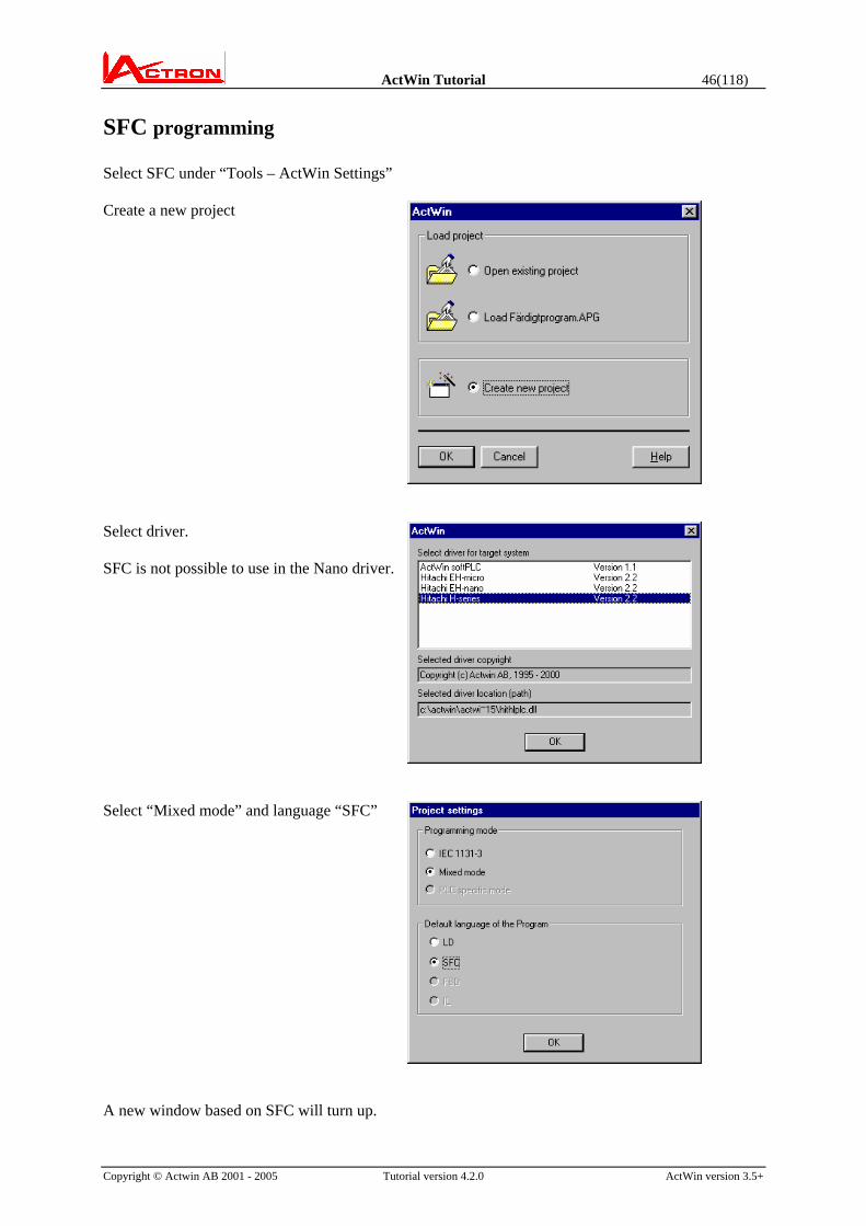
SFC programming Select SFC under “Tools – ActWin Settings” Create a new project
Select driver. SFC is not possible to use in the Nano driver.
Select “Mixed mode” and language “SFC”
A new window based on SFC will turn up.

ActWin Tutorial 47(118)
Copyright © Actwin AB 2001 - 2005 Tutorial version 4.2.0 ActWin version 3.5+
SFC in the IEC 61131 standard is the programming language, which is the upper structure of a project. It takes care of the sequence flow and uses the other programming languages in different parts where it is natural. ActWin also allow let you make the complete program inside the SFC in a comfortable way. The principal of SFC programming is basically very simple. There are steps. These define states where one or more action takes place.
Normal step Start step (one per network)
There are transitions. This defines the condition to move from one step to another.

ActWin Tutorial 48(118)
Copyright © Actwin AB 2001 - 2005 Tutorial version 4.2.0 ActWin version 3.5+
There are two different types of branches. Alternative branch: This means that the flow will be controlled by the transition, which is true. If both are true, there is a possibility to decide the priority by the user. (The default priority is from left to right)
Parallel branch: This means that the flow will occur in both branches simultaneously. The flow will not leave the parallel branches before the last step in each branch is on and the transition following is true.
Action An action is something, which happens when a step is activated. It can be all from setting an output to an activation of a complete sub program. Ladder action: A ladder action is given a name. It contains a complete ladder diagram of any size.
Symbol action: ActWin will allow you to create a Symbol action, which means output control of one symbol, e.g. activation of a motor. This gives an extended comfort in the programming as the majority of actions in a normal program are of this type.
Every action can have a Qualifier This means that you can use e.g. time delays “D”, Set “S” and Reset “R” on an action. If you want the Motor in the example above to start 1.5 s after the step is active then you exchange the N to a D and set the time to 1.5 s. More details about this will follow. Transition There are also two types of transitions: Ladder transition: You can define a condition consisting of one rung of any size including compare functions. The output of the rung is the condition for the transition. Symbol transition: Most transitions are only one simple condition, e.g. an input like “Start_button”. Therefor ActWin allows you to define a “Symbol transition”

ActWin Tutorial 49(118)
Copyright © Actwin AB 2001 - 2005 Tutorial version 4.2.0 ActWin version 3.5+
Start to get used to building a network ActWin has a unique user interface in the design of networks. It is totally dynamic. It will keep the network syntax correct all the time. This feature also means that a real On-Line programming in SFC is possible and supported. There are no specific tools that have to be changed from action to action. This creates a high degree of comfort.
Start to get help from the “Grid help” A grid will appear on the network showing where insertion is possible. Possible to insert Actions Possible to insert Transition- Step Possible to insert Alternative branch Possible to insert Transition Possible to insert Step – Transition Possible to insert Parallel branch
When you move the mouse from the button only the grid will remain. You can always go back and press the button again to get the detailed help. When you get used to the editing you can turn the grid off to get a cleaner network.
Start to insert a new step plus transition. When the mouse arrow is inside the grid the symbol for what is possible to do appears.
Click with the mouse and insert a new step.
Use the same method for branches. When you add a branch a grid showing all available connection points will come up.

ActWin Tutorial 50(118)
Copyright © Actwin AB 2001 - 2005 Tutorial version 4.2.0 ActWin version 3.5+
Click on one of the connection points
A parallel branch is created. Click here to expand the branch. After a short while you will get used to the way of editing and you do not need the grid.
Let us turn off the grid help.
Insert transitions.
Select Symbol transition or Ladder transition. If it is a single symbol you will get the address Search/Enter dialog. If it is a Ladder action you can Enter a name. To create the ladder condition, see example project later in the tutorial. Insert an action.
You will get the Action selection and search box. Select BOOL (Symbol) or LD action and enter a name and address (if it is symbol)
If it is a Ladder action there will be an indicating that it contains code. If you click on it then the action will be hidden.

ActWin Tutorial 51(118)
Copyright © Actwin AB 2001 - 2005 Tutorial version 4.2.0 ActWin version 3.5+
Click on the and you will get a window where you can edit the action (program) code. (see Ladder editing) When you are done, click on the “main program folder” to go back to the SFC.
If you select you will see all places where you can insert a Comment. To edit the complete graph or if you want to mark the graph, right click on the network comment. This will allow you to create a New network, a new Activity Condition or a Reset Condition
Use the zoom tools When the graph is marked you can zoom it individually
small zoom tiny zoom
Continue to get used to the editing method

ActWin Tutorial 52(118)
Copyright © Actwin AB 2001 - 2005 Tutorial version 4.2.0 ActWin version 3.5+
Start a project Let us make a small project:
A simple example showing the simplicity of ActWin SFC
The Green lamp will be lit in the start. When the operator pushes the Start button the conveyor will start (the condition is that the Photo switch in the end of the conveyor is not on and the Lift is down.) When the item passes the Photo switch the lift will go up after 1 s. The Red lamp will be lit when the lift is moving up and down. When the lift reaches the top position the pusher will go out until it reaches the end position. After 1.5 s the pusher will go back simultaneously as the lift goes down. When the lift is down and the pusher is back the machine is ready for a new item and starts from the beginning again. There is an Auto/Manual switch. In Manual mode the Manual Pushbuttons are valid for control of the Conveyor, Lift Up, Lift Down, Pusher Out, Pusher In and Upper Conveyor. There is also one Reset button. If the operator wants to break the process and start from the beginning this button will be used.
Operator Panel: • Start button • Red Lamp • Green Lamp • Reset Button • Auto/Manual SW • 6 manual buttons
Conveyor
End pos pusher Pusher End pos Lift Top PhotoSw sensor Lift End pos Lift Low
Item
Conveyor (manual)

ActWin Tutorial 53(118)
Copyright © Actwin AB 2001 - 2005 Tutorial version 4.2.0 ActWin version 3.5+
Start to make a hardware configuration. This time we will use a EH150 with the EH-BS5 rack..
Right click on the EH_XD16 module and start the input allocation (of the already know inputs). Continue afterwards with the output allocation. Use the buttons to go from one module to another.
In the first step the Green Lamp will be on. Click in the Action field
A window will appear, where you can Add the symbol “Green_Lamp”. As this is a single symbol, select BOOL

ActWin Tutorial 54(118)
Copyright © Actwin AB 2001 - 2005 Tutorial version 4.2.0 ActWin version 3.5+
The step will now show the symbol action Green_Lamp. The next transition will be the start condition. This is a combination of inputs, so we have to use a ladder rung. Click on the transition field. Select LD. Give the transition a descriptive name. e.g. “Startcondition”
Press OK and the network will look like this: To define the ladder condition, double click on the rung. The ladder-editing window will open. Use the same tools as in ActWin Ladder programming.
The start condition is that the Lift is down, the Photo switch on the conveyor is not darkened and the operator pushes the start button. Press the “main” folder to return to SFC
The transition now looks like this. Observe that there is a zoom button on the steps and actions that contain something. Click on the
The transition will look like this:

ActWin Tutorial 55(118)
Copyright © Actwin AB 2001 - 2005 Tutorial version 4.2.0 ActWin version 3.5+
Insert a new step/transition. The conveyor shall move in the next step. Insert the symbol output “Conveyor” The next transition is the Photo switch, which can be inserted as a single symbol.
The symbol transition does not need a ladder rung and it will look like this.
Insert a new Step/Transition When the photo switch indicates the Lift shall go up. Insert the output symbol “Lift_up”. But it shall be a delay of 1 s. Select the Qualifier D (Delay) by right clicking on the “N” and set 1 s.
ActWin Tutorial 56(118)
Copyright © Actwin AB 2001 - 2005 Tutorial version 4.2.0 ActWin version 3.5+
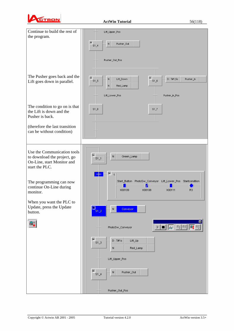
Continue to build the rest of the program. The Pusher goes back and the Lift goes down in parallel. The condition to go on is that the Lift is down and the Pusher is back. (therefore the last transition can be without condition)
Use the Communication tools to download the project, go On-Line, start Monitor and start the PLC. The programming can now continue On-Line during monitor. When you want the PLC to Update, press the Update button.

ActWin Tutorial 57(118)
Copyright © Actwin AB 2001 - 2005 Tutorial version 4.2.0 ActWin version 3.5+
Create Activity condition for the graph We have created the automatic sequence and we want to use the AUTO_Manual switch. Therefor we use the Activity condition. Right click on the network comment and select “Activity Condition”
An activity condition above the network appears. Open and define the condition.
Double clicks on the rung to edit the content just like a transition. To go back to the network, press
(Do not forget to press Update when you want the On-Line Update)
The network will now be monitored with the Activity condition. In AUTO mode (X100 ON) the flow will be as before. In Manual mode (X100 OFF) the flow will be frozen and the outputs (actions) in the network will not be activated.

ActWin Tutorial 58(118)
Copyright © Actwin AB 2001 - 2005 Tutorial version 4.2.0 ActWin version 3.5+
Add a Reset condition. The procedure is the same as to add an Activity Condition. When the RESET condition is ON all steps will be disactivated except the Start step, which will be activated. This makes it possible to start the process from the beginning.
Zoom in the conditions. Now the automatic control of the machine works. We also need a Hand control. These conditions will be described separately.
A very good way to do that is to use a ladder action and simply describe the logic’s in ladder. Make a new network. The only purpose with the network is to keep the new Ladder action. Therefor it will only have a start step and no condition on the transition.
Create a Ladder action.
Open the ladder action

ActWin Tutorial 59(118)
Copyright © Actwin AB 2001 - 2005 Tutorial version 4.2.0 ActWin version 3.5+
Create the typical hand control.
As the hand control only shall be valid in Hand (manual) mode the last thing we have to do is to define the Activity condition.
This is a special way of using a one step network and a Ladder action. There are some more information you have to know, which is due to the standard itself. *1
*1 Note that when you use Ladder actions in other cases an output will keep the status when it leaves the step if you do not connect a special symbol in series with the output. The symbol is called <LadderActionName>.Q In this case “Hand_Control.Q”. An action will be executed one time after it leaves the step. E.g. a counter will count an extra time if you do not connect this special symbol in series. (This could be a little confusing. But it is a consequence of the IEC1131 standard.)

ActWin Tutorial 60(118)
Copyright © Actwin AB 2001 - 2005 Tutorial version 4.2.0 ActWin version 3.5+
Zoom the networks and start the next network Continue to program.
Print the project The documentation procedure is identical to the ladder documentation. Each network will be presented and scaled down to one paper. If the network is too big to be clearly read on one page a number of pages containing the network in full scale but splited will follow. These pages can be put together to a large page for a complete overview.

ActWin Tutorial 61(118)
Copyright © Actwin AB 2001 - 2005 Tutorial version 4.2.0 ActWin version 3.5+
FBD programming Create a new project.
Select driver.
Select programming mode ”IEC 1131-3” and select language “FBD”.
A new window based on FBD will turn up.
The editing screen is blank.
ActWin Tutorial 62(118)
Copyright © Actwin AB 2001 - 2005 Tutorial version 4.2.0 ActWin version 3.5+
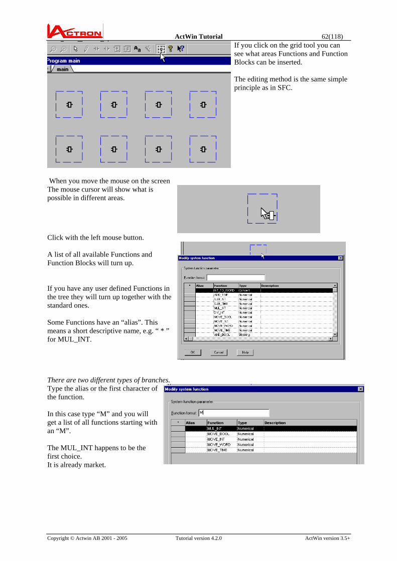
If you click on the grid tool you can see what areas Functions and Function Blocks can be inserted. The editing method is the same simple principle as in SFC.
When you move the mouse on the screen The mouse cursor will show what is possible in different areas.
Click with the left mouse button. A list of all available Functions and Function Blocks will turn up. If you have any user defined Functions in the tree they will turn up together with the standard ones. Some Functions have an “alias”. This means a short descriptive name, e.g. “ * ” for MUL_INT.
There are two different types of branches. Type the alias or the first character of the function. In this case type “M” and you will get a list of all functions starting with an “M”. The MUL_INT happens to be the first choice. It is already market.

ActWin Tutorial 63(118)
Copyright © Actwin AB 2001 - 2005 Tutorial version 4.2.0 ActWin version 3.5+
Press Enter and the Function will appear on the screen.
Insert a second function. In this case we want an ADD_INT.
Continue to build the FBD.
If the function is not on the top when you type the first character, continue to type until it is significant or just scroll down to the wanted Function and press Enter.

ActWin Tutorial 64(118)
Copyright © Actwin AB 2001 - 2005 Tutorial version 4.2.0 ActWin version 3.5+
How to connect the Functions Move the cursor close to the output connection. In this area the cursor will symbolize a connection. Left click and a selection between a line connection and a Symbol connection will be shown.
The default is a line connection. This means that if you only click the FBD will look like this when you release the mouse button.
This symbol means a possible connection point of the right type. (in this case an INT)
Click again where you want to connect.
and the line will be connected.
Connect the other line. On the inputs of the ADD_INT and MUL_INT functions and on the output of the DIV_INT we want to connect Symbols in stead of connection lines. Click as before on the connection.

ActWin Tutorial 65(118)
Copyright © Actwin AB 2001 - 2005 Tutorial version 4.2.0 ActWin version 3.5+
But instead of immediately releasing the mouse button, drag the mouse down to the “S” , which stands for Symbol. Release the mouse button.
The Symbol selection and search window will show up. Type the Symbol name and select the address. In this case we leave it without address.
Connect the other input connections. The method is the same, but the only choice is Symbol.
Connect Factor1 and Factor2 to the MUL_INT without addresses and Analog_Input1, which is connected to the first physical analog input, to the ADD_INT.
Connect a Constant instead of a symbol to the other input of the ADD_INT.
ActWin Tutorial 66(118)
Copyright © Actwin AB 2001 - 2005 Tutorial version 4.2.0 ActWin version 3.5+
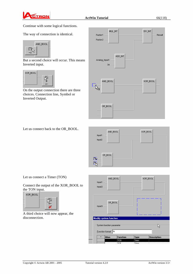
Continue with some logical functions. The way of connection is identical.
But a second choice will occur. This means Inverted input.
On the output connection there are three choices. Connection line, Symbol or Inverted Output.
Let us connect back to the OR_BOOL.
Let us connect a Timer (TON) Connect the output of the XOR_BOOL to the TON input.
A third choice will now appear, the disconnection.

ActWin Tutorial 67(118)
Copyright © Actwin AB 2001 - 2005 Tutorial version 4.2.0 ActWin version 3.5+
The diagram will automatically redraw in the most efficient way. Connect the Timer output and the Elapsed time (ET) to symbols. Let us preset the Timer with the value of above calculation symbol “Result”. ET and PT (Preset time) are of the type Time. But “Result” is of the type INT. This means that we have to make conversion.
Insert a INT_TO_TIME function. It is now OK to connect to the PT input of the TON. But the two boxes are far away from each other on the screen. Let us rearrange. To move a function or Function Block, place the cursor on the element, hold down and move to one of the marked areas.
The result will be:

ActWin Tutorial 68(118)
Copyright © Actwin AB 2001 - 2005 Tutorial version 4.2.0 ActWin version 3.5+
Go On-Line, start and go into Monitor and you can follow the process.
You can insert user defined Functions and Function blocks All the Functions and FBs in the tree will be present in the list.
How to produce your own Functions and Function blocks, see the General tutorial. Connect the inputs and outputs as described above.
ActWin Tutorial 69(118)
Copyright © Actwin AB 2001 - 2005 Tutorial version 4.2.0 ActWin version 3.5+
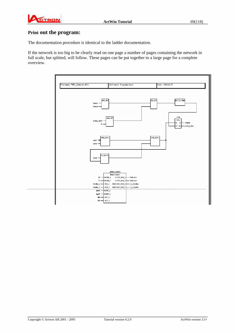
Print out the program: The documentation procedure is identical to the ladder documentation. If the network is too big to be clearly read on one page a number of pages containing the network in full scale, but splitted, will follow. These pages can be put together to a large page for a complete overview.

ActWin Tutorial 70(118)
Copyright © Actwin AB 2001 - 2005 Tutorial version 4.2.0 ActWin version 3.5+
IL programming Create a new project.
Select driver.
Select programming mode “IEC 1131-3” and language “IL”
A new window based on IL will turn up.
The editing screen is blank. The cursor points on the first Line.

ActWin Tutorial 71(118)
Copyright © Actwin AB 2001 - 2005 Tutorial version 4.2.0 ActWin version 3.5+
This is a text editor. But it has got a strong syntax check during the editing. Therefore it is controlled by a “Wizard”, which helps you e.g. to find and enter the correct symbols.
Start to write the first instruction. If this is e.g. “LD” (Load) then you type “L”. The wizard will appear showing all available instructions starting with an L. The alternative LD is already marked. Therefore press Enter. This will select LD and go to the next phase, which is the symbol allocation.
There is an alternative to selecting the instruction with Enter. If you press space the instruction will be selected but you will still stay in the instruction selection window. When a complete instruction is present in the Operator/FUN window and you press <Space> you will also turn to the symbol allocation window. This means that you can use the same keystroke as in free text. The difference is that you will get a syntax check in addition. In next version you will be able to select a “free text” mode. This means that the wizard will help you in the background.

ActWin Tutorial 72(118)
Copyright © Actwin AB 2001 - 2005 Tutorial version 4.2.0 ActWin version 3.5+
Now you can Enter or search for the symbol. The Instruction line is built up here. The Symbol is entered here.
Enter an Input “Start_Button”
Press Enter and the result is:
Continue with the next line. Let us enter a ANDN. Move down to the ANDN instruction and press Enter. You can also use the “alias” starting with an N.

ActWin Tutorial 73(118)
Copyright © Actwin AB 2001 - 2005 Tutorial version 4.2.0 ActWin version 3.5+
The program is built up. To enter a comment, type here. To enter a label for the line, type here.
The result is:
To enter a line comment, go to the line and press Ins.
Press enter and leave the Operator/FUN field free. Just type a Line comment.
To use a Function Block, e.g. a Timer (TON) or a counter. Use the CAL instruction, then select TON.
ActWin Tutorial 74(118)
Copyright © Actwin AB 2001 - 2005 Tutorial version 4.2.0 ActWin version 3.5+
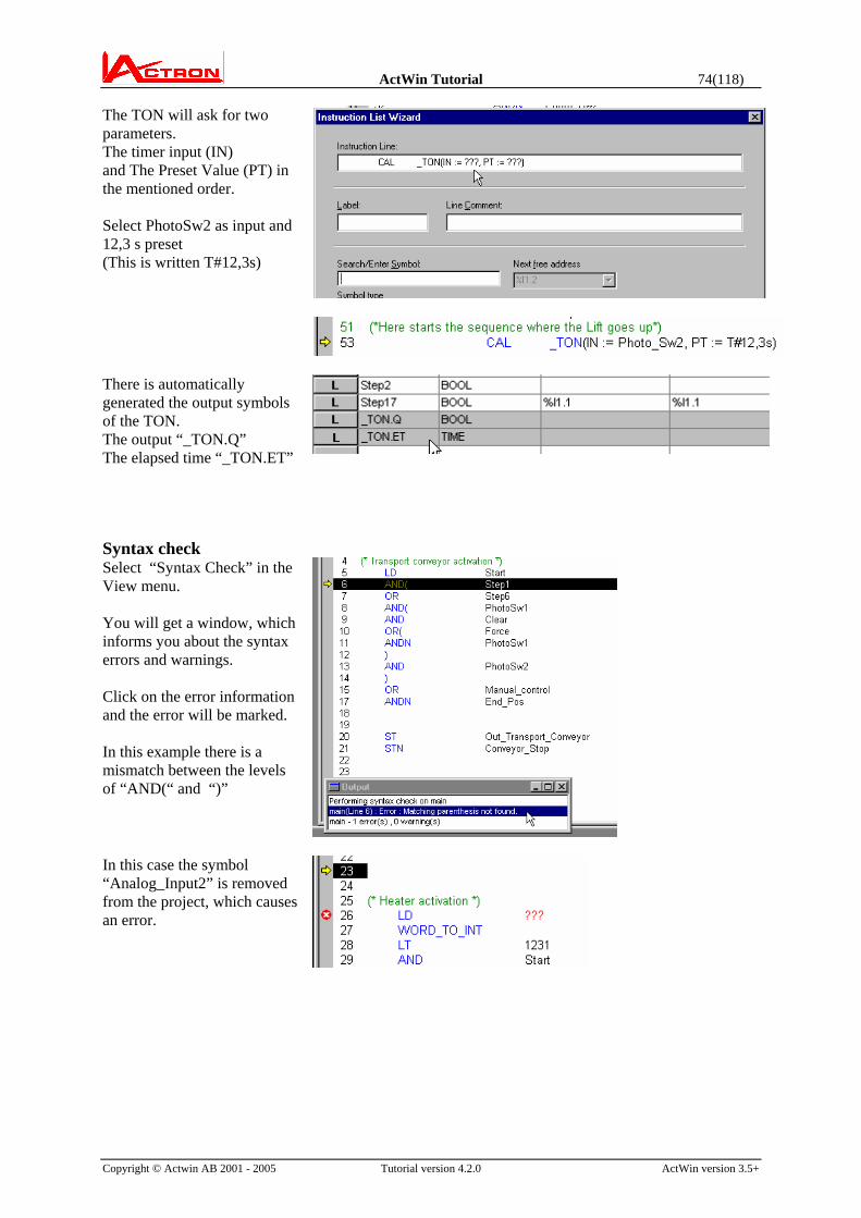
The TON will ask for two parameters. The timer input (IN) and The Preset Value (PT) in the mentioned order. Select PhotoSw2 as input and 12,3 s preset (This is written T#12,3s)
There is automatically generated the output symbols of the TON. The output “_TON.Q” The elapsed time “_TON.ET”
Syntax check Select “Syntax Check” in the View menu. You will get a window, which informs you about the syntax errors and warnings. Click on the error information and the error will be marked. In this example there is a mismatch between the levels of “AND(“ and “)”
In this case the symbol “Analog_Input2” is removed from the project, which causes an error.

ActWin Tutorial 75(118)
Copyright © Actwin AB 2001 - 2005 Tutorial version 4.2.0 ActWin version 3.5+
Copy and past in the program Mark the instructions with the mouse. Use the Copy, Cut and Paste commands.
On-Line and Monitoring Use the On-Line tools in the same way as for the other languages. The Monitor values are present on the right side of the IL.
ActWin Tutorial 76(118)
Copyright © Actwin AB 2001 - 2005 Tutorial version 4.2.0 ActWin version 3.5+
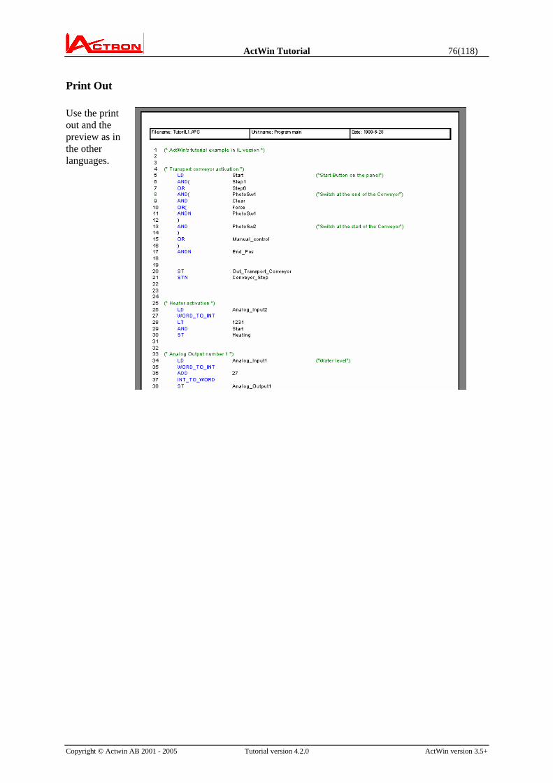
Print Out Use the print out and the preview as in the other languages.

ActWin Tutorial 77(118)
Copyright © Actwin AB 2001 - 2005 Tutorial version 4.2.0 ActWin version 3.5+
Appendix A: Ladder editing old mode. Ladder editing buttons:
Following tools are available
1. Selection 2. Line draw 3. Contact symbol 4. Coil symbol 5. Arithmetic instruction(s) 6. Function box (e.g. Compare box) 7. Compare box 8. Rung Comment or Section comment
1 2 3 4 5 6 7 8
Select the contact symbol with the mouse or press the F10 button.
Create a contact: Move the mouse approximately to the place where you want the contact
Click and keep the left button of the mouse down until you see the symbol below and drop the contact.
Keyboard editing: Move the cursor with the arrow buttons and press Enter or (Shift+Enter)
→
ActWin Tutorial 78(118)
Copyright © Actwin AB 2001 - 2005 Tutorial version 4.2.0 ActWin version 3.5+
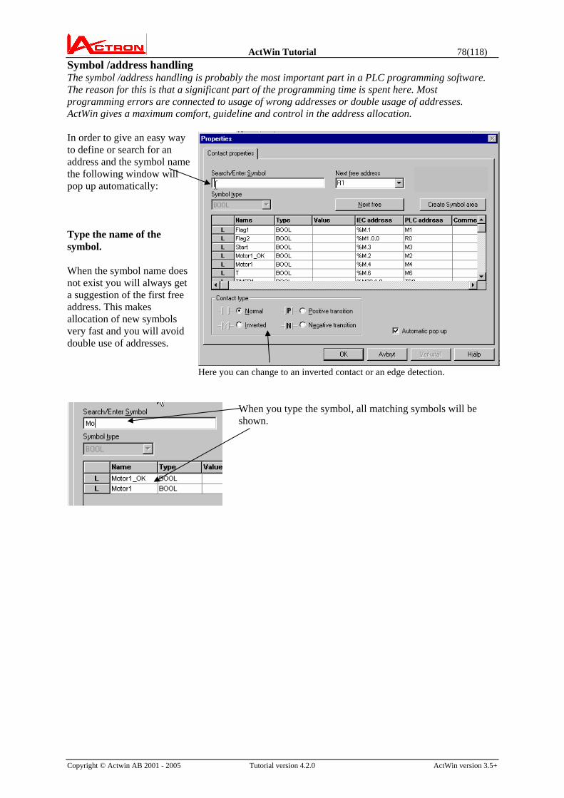
Symbol /address handling The symbol /address handling is probably the most important part in a PLC programming software. The reason for this is that a significant part of the programming time is spent here. Most programming errors are connected to usage of wrong addresses or double usage of addresses. ActWin gives a maximum comfort, guideline and control in the address allocation. In order to give an easy way to define or search for an address and the symbol name the following window will pop up automatically: Type the name of the symbol. When the symbol name does not exist you will always get a suggestion of the first free address. This makes allocation of new symbols very fast and you will avoid double use of addresses.
Here you can change to an inverted contact or an edge detection.
When you type the symbol, all matching symbols will be shown.

ActWin Tutorial 79(118)
Copyright © Actwin AB 2001 - 2005 Tutorial version 4.2.0 ActWin version 3.5+
Select an existing symbol Instead of typing the entire symbol name, you can click in the list and select the symbol you want.
Create a new symbol A new symbol does not have any match. If the suggested address is OK you can press Enter to create the symbol.
Select an address type for the symbol If you want a special address, then click on the Memory address and select the type you want. You can also type the address with the number directly in the Memory address window.
Select the address number The first available address of the type you suggested will be suggested. Accept or type the number you want and press Enter for OK.
You can also press the button to get the next available address.
Using addresses directly Even though it is not recommended it can in some cases be comfortable to use the address directly. Just type the address. The symbol on that address will be used or if there is no symbol a new temporary symbol “__Y200” will be created. (All addresses have to have a symbol) Play a little with the symbol handling and get used to this method and you will realise the comfort.
The button allows you to define any number of symbols in a one operation. (see “arithmetic box” description for more details.)

ActWin Tutorial 80(118)
Copyright © Actwin AB 2001 - 2005 Tutorial version 4.2.0 ActWin version 3.5+
Make a serial connection Repeat the procedure with the contact and drop the new contact close to the right side of the first one. As you can see, the editing field of the rung is marked (shown as deeper). This means that the rung is not ready and approved by ActWin. When it is completed the marking will disappear. Give the new contact a symbol name and an address: The new symbols will appear in the symbol window. This window will also inform about type, (start value) PLC address and the corresponding IEC1131 address (used if IEC1131-programming is selected)
Ladder editing without symbols In order to make some different ladder editing without the symbol procedure for each contact, we can turn the symbol editing off. Make a new contact in series. But instead of giving a symbol name, disable ”Automatic pop up” and press OK. (You can also fetch this window, the Contact Properties, by right-clicking
on a contact)
The contact will be drawn without symbol and address

ActWin Tutorial 81(118)
Copyright © Actwin AB 2001 - 2005 Tutorial version 4.2.0 ActWin version 3.5+
To make an inverted contact, Press the Shift key before you hold the left button on the mouse down. (This can also be changed in the Contact Properties
Window) Note that the width of the ladder diagram is flexible. (the right power line moves rightwards) To make a parallel connection Place the mouse arrow on the horizontal line where the parallel connections shall start. Press the left button and drag the mouse down
Continue to drag the mouse around the contacts you want to connect in parallel. When you reach the horizontal line again, then release the left button.
The connection is completed. Keyboard editing Use the keyboard arrows. Press <Ins>. in the start point and complete with <Enter> in the end point.
To insert a parallel connection Make the same procedure as above inside the other connection.
When you drop the mouse button, then the circuit will be redrawn in a proper way.

ActWin Tutorial 82(118)
Copyright © Actwin AB 2001 - 2005 Tutorial version 4.2.0 ActWin version 3.5+
To connect a contact in series Place the mouse arrow on the line where you want the contact. Press the left button and drop the contact.
To insert a contact in series Place the mouse arrow on the line between the contacts where you want the contact. Press the left button and drop the contact.
To draw a vertical line
Press the line draw tool on the toolbar. Place the mouse on the line where you want you to start. Press the left mouse button and drag to the line where you want to end. Release the button and the line will be completed.
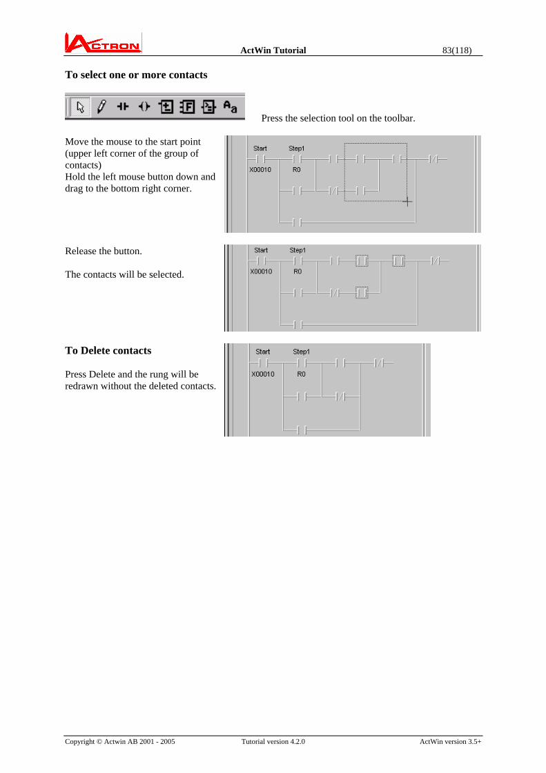
ActWin Tutorial 83(118)
Copyright © Actwin AB 2001 - 2005 Tutorial version 4.2.0 ActWin version 3.5+
To select one or more contacts
Press the selection tool on the toolbar. Move the mouse to the start point (upper left corner of the group of contacts) Hold the left mouse button down and drag to the bottom right corner.
Release the button. The contacts will be selected.
To Delete contacts Press Delete and the rung will be redrawn without the deleted contacts.
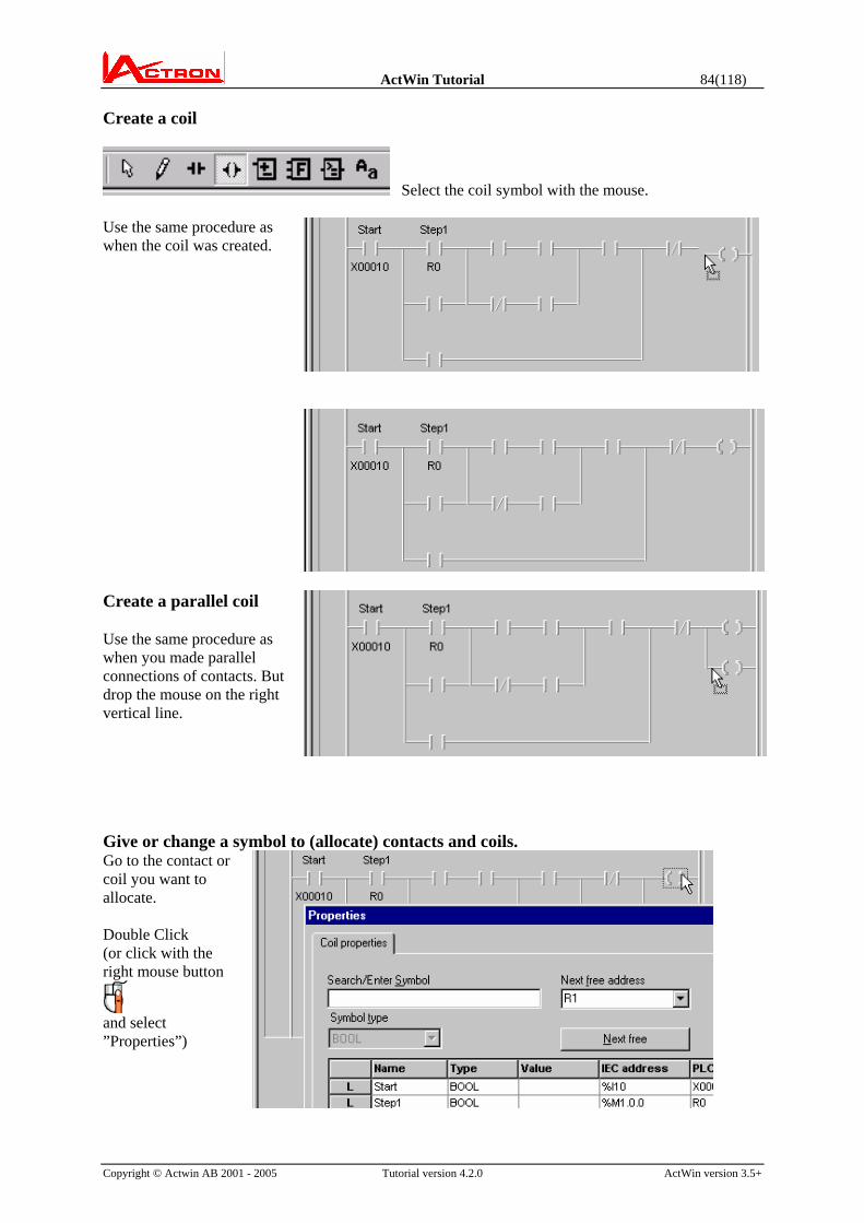
ActWin Tutorial 84(118)
Copyright © Actwin AB 2001 - 2005 Tutorial version 4.2.0 ActWin version 3.5+
Create a coil
Select the coil symbol with the mouse. Use the same procedure as when the coil was created.
Create a parallel coil Use the same procedure as when you made parallel connections of contacts. But drop the mouse on the right vertical line.
Give or change a symbol to (allocate) contacts and coils. Go to the contact or coil you want to allocate. Double Click (or click with the right mouse button
and select ”Properties”)

ActWin Tutorial 85(118)
Copyright © Actwin AB 2001 - 2005 Tutorial version 4.2.0 ActWin version 3.5+
The Symbol selection and search window will appear. Type the new symbol name. (You are not limited to any length of the symbol. Just use a significant, but not too long symbol names out of practical reason. Note that blanks are not allowed.)
In this case, select Y for output.
If you have not decided the address number from the beginning, press ”Next free” and the software will suggest the first free unused output address.
Press OK and the coil is allocated. Continue with the same procedure or select already existing symbols from the list.
Note that before the rung was completed it was shown on a “lower level” When the rung is completed and approved by ActWin the marking disappears.
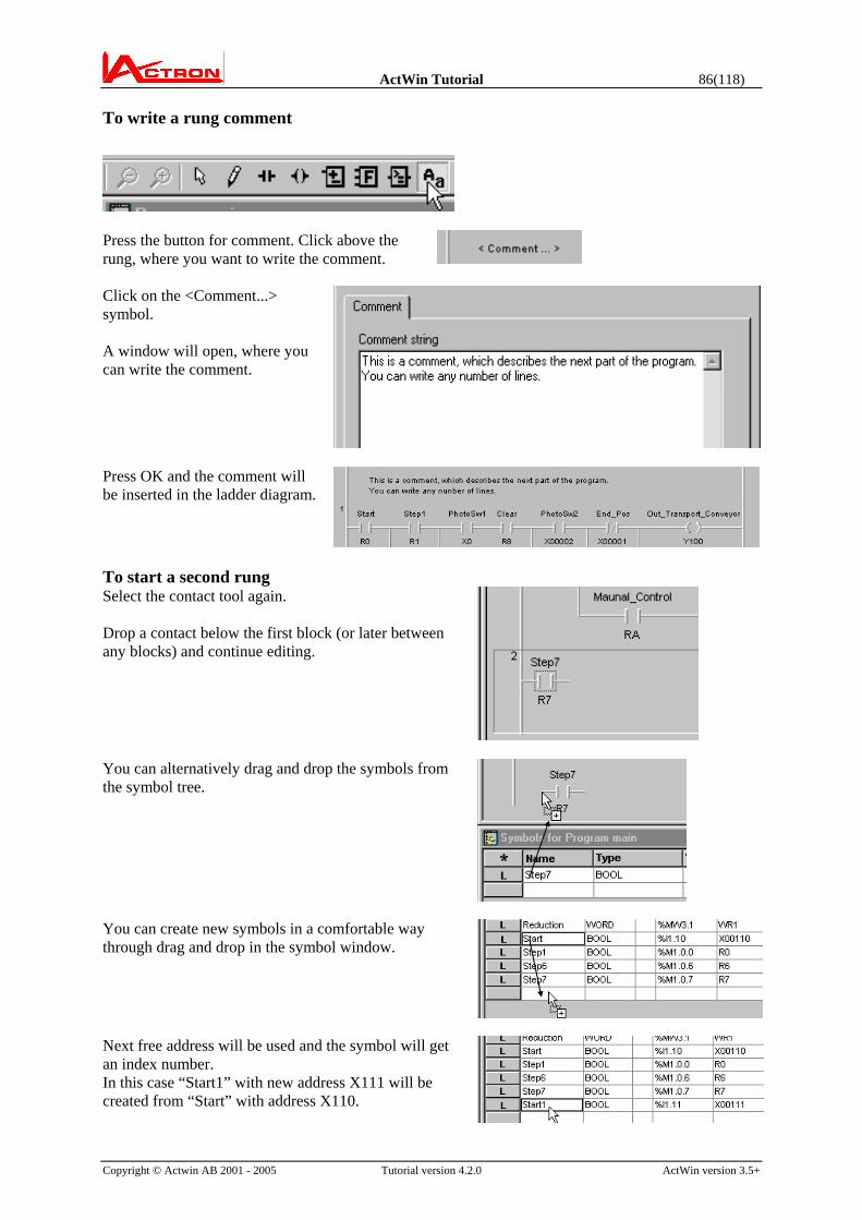
ActWin Tutorial 86(118)
Copyright © Actwin AB 2001 - 2005 Tutorial version 4.2.0 ActWin version 3.5+
To write a rung comment
Press the button for comment. Click above the rung, where you want to write the comment. Click on the <Comment...> symbol. A window will open, where you can write the comment.
Press OK and the comment will be inserted in the ladder diagram.
To start a second rung Select the contact tool again. Drop a contact below the first block (or later between any blocks) and continue editing.
You can alternatively drag and drop the symbols from the symbol tree.
You can create new symbols in a comfortable way through drag and drop in the symbol window.
Next free address will be used and the symbol will get an index number. In this case “Start1” with new address X111 will be created from “Start” with address X110.

ActWin Tutorial 87(118)
Copyright © Actwin AB 2001 - 2005 Tutorial version 4.2.0 ActWin version 3.5+
The system library Open the system library, where you will find ”Hitachi H-series” Open this and you will find three folders. One contains H-specific Functions. The other two contain IEC-specific functions. Depending on the mode we have selected under ”Tools-ActWin Settings-Programming”
the folders are open or locked, e.g. . In this case the only open folder is the ”PLC-specific”
To make a compare box or to insert a F or FB: Select the Function tool.
There is now a very quick way of selecting the functions. You will get a list of available functions. Every function has an “alias”, which means a short logical name. You can scroll down and select the right function.
You can find the right function by typing the beginning of the alias or the beginning of the function name. There is a also a more detailed description of the functions.

ActWin Tutorial 88(118)
Copyright © Actwin AB 2001 - 2005 Tutorial version 4.2.0 ActWin version 3.5+
Click and keep the left mouse button down on the function and drag it approximately to the place where you want to connect it.
You can also insert a function in the ladder diagram (the upper line is the logic condition for the comparison) Drop the button and the function is connected. The two lower lines are the values. To allocate the value lines, double click on the line and define a value or a contant.
To create a User defined Function (F) or Function Block (FB): A part of a program, that will be repeated in the same program or in other programs can be included in a Function or a Function Block. (this must be done in IEC or mixed mode) The difference between Functions and Function Blocks is that a Function does not keep any memory and it is therefore always possible to tell the result of a Function calculation just by looking at it. E.g. an ADD_INT is a function.
A Function Block can keep a status from execution to execution. E.g. a CTU or a TON are Function Blocks.
It is possible to create user defined Functions and FBs.

ActWin Tutorial 89(118)
Copyright © Actwin AB 2001 - 2005 Tutorial version 4.2.0 ActWin version 3.5+
Create a Function Block Right click on the Project Folder and select New Function Block... (also possible from the Insert-menu.)
Give a name to the FB.
The new Function Block appears in the tree.
Double click on the new FB and a new window will appear where you can start to define the FB.
In the application we are producing we use a calculation for water Flow several times. The in parameters are different pulse counters. Build the content of the FB exactly like you build a program. You can also take a part from an existing program simply by Copy and Paste from the program to the FB. There are no physical addresses in the FB. But you have to define if they are Input addresses, Output addresses or if they are only to be represented Locally in the FB

ActWin Tutorial 90(118)
Copyright © Actwin AB 2001 - 2005 Tutorial version 4.2.0 ActWin version 3.5+
. Go to the Symbol Window that has been automatically created for the FB. Double click on the L. “L” stands for Local and all symbols will be Local by default. The property window for the symbol appears. You can now select if you want to change to an Input or Output symbol. Repeat for the other symbols. You can also use these buttons to go quickly between the symbols.
In this case we only need one Input and one Output symbol. The others can stay Local. Go back to the Main program through clicking on the Main folder at the top of the project tree.
The new Function Block is now present in the tree. This means that you can use this block one or several times in the program. Drag the FB from the tree and drop it in the program
Connect an input and an output to the FB.
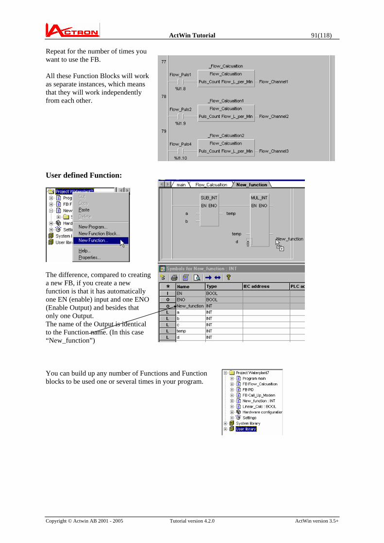
ActWin Tutorial 91(118)
Copyright © Actwin AB 2001 - 2005 Tutorial version 4.2.0 ActWin version 3.5+
Repeat for the number of times you want to use the FB. All these Function Blocks will work as separate instances, which means that they will work independently from each other.
User defined Function:
The difference, compared to creating a new FB, if you create a new function is that it has automatically one EN (enable) input and one ENO (Enable Output) and besides that only one Output. The name of the Output is identical to the Function name. (In this case “New_function”) You can build up any number of Functions and Function blocks to be used one or several times in your program.

ActWin Tutorial 92(118)
Copyright © Actwin AB 2001 - 2005 Tutorial version 4.2.0 ActWin version 3.5+
Appendix B: ActWin Macro The macro handling in ActWin will allow you:
to create any kind of an “H specific Function block” or Macro.
to control fixed addresses, such as specific IO modules etc. which is impossible with standard FB.
Therefore the macro handling in ActWin will allow for the usage of (for the average user) complicated coding and complex modules.
This Tech note describes how to create a macro and how to use it in a program. How to create a Macro Example of a macro to the EH-CU module, the counter module to EH150 system.
First write the code for the part of the program you want to transfer to a macro in the normal way or copy from an existing project. (The code can also be written or modified inside the macro itself.)

ActWin Tutorial 93(118)
Copyright © Actwin AB 2001 - 2005 Tutorial version 4.2.0 ActWin version 3.5+
The general code for an EH CU can look as follows:

ActWin Tutorial 94(118)
Copyright © Actwin AB 2001 - 2005 Tutorial version 4.2.0 ActWin version 3.5+

ActWin Tutorial 95(118)
Copyright © Actwin AB 2001 - 2005 Tutorial version 4.2.0 ActWin version 3.5+
It is clear that this is difficult to write each time for an average programmer and it takes very long time even for an expert.
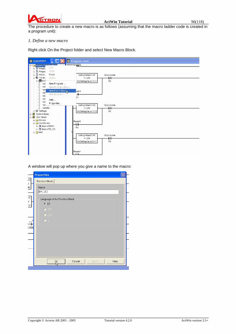
ActWin Tutorial 96(118)
Copyright © Actwin AB 2001 - 2005 Tutorial version 4.2.0 ActWin version 3.5+
The procedure to create a new macro is as follows (assuming that the macro ladder code is created in a program unit): 1. Define a new macro Right click On the Project folder and select New Macro Block.
A window will pop up where you give a name to the macro:

ActWin Tutorial 97(118)
Copyright © Actwin AB 2001 - 2005 Tutorial version 4.2.0 ActWin version 3.5+
A new empty “macro” program unit is now created with a new tab in the programming window.
2. Insert the macro code Go back to the program. Mark all rungs and copy.

ActWin Tutorial 98(118)
Copyright © Actwin AB 2001 - 2005 Tutorial version 4.2.0 ActWin version 3.5+
Go back to the macro and paste:
The program code will be inserted in the Macro. 3. Now the symbols have to be defined: As default all symbols are Local. This means in this case that they will not be shown outside the macro box. To view and access the symbols in the ladder diagram they have to be defined as Input or Output.
Mark the symbol and right click and select Properties.

ActWin Tutorial 99(118)
Copyright © Actwin AB 2001 - 2005 Tutorial version 4.2.0 ActWin version 3.5+
Select Input, Output or Local. In the box you can also select if the symbol shall be on a fixed address. E.g. the Init pulse R7E7 or the real time clock are always fixed addresses. This means that the macro shall always select this physical address. You can also select if the address shall be confirmed by the user when the macro is inserted. E.g. an hardware address belonging to an I/O board will be different depending on where in the rack the modules is and the user can select which module the macro belongs to. The macro symbol allocation is described more detailed later in this document.

ActWin Tutorial 100(118)
Copyright © Actwin AB 2001 - 2005 Tutorial version 4.2.0 ActWin version 3.5+
There is a more comfortable way to select if the symbol shall be Input, Output or Local. Just mark all symbols of one kind in the symbol window.
And press the button “L”, “I” or “O”. All the symbols will change type simultaneously.
Observe that “Local” is not exactly the same as a Local in IEC61131. A local can be used in the main program. In such case the symbol name used will be <macro name>.<Symbol of the Local>. E.g. “Markerenable1” can be referred as “_EH_CU.Markerenable1” in the program. When a macro is inserted into the project the macro symbols will be allocated as follows: Generally, if a symbol is not defined as Confirm or Fixed, ActWin will select a free address when the macro is inserted in the project. In the special case when symbols with overlapping addresses exists, e.g. M0 is used as well as WM0 (or WM21 as well as DM20), then they will normally be allocated together also after inserting the macro even if the actual address could be different. This default behavior can be modified by using the Confirm or Fixed settings or by defining arrays (see below).
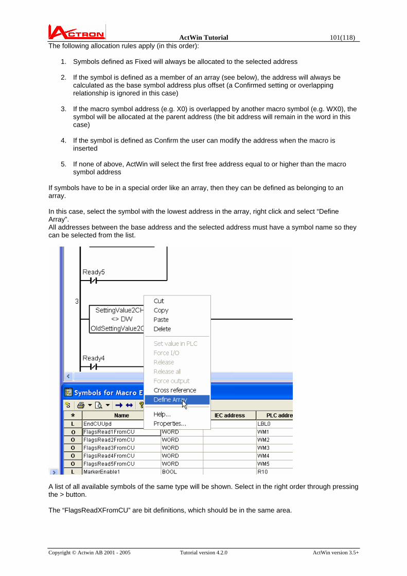
ActWin Tutorial 101(118)
Copyright © Actwin AB 2001 - 2005 Tutorial version 4.2.0 ActWin version 3.5+
The following allocation rules apply (in this order):
1. Symbols defined as Fixed will always be allocated to the selected address
2. If the symbol is defined as a member of an array (see below), the address will always be calculated as the base symbol address plus offset (a Confirmed setting or overlapping relationship is ignored in this case)
3. If the macro symbol address (e.g. X0) is overlapped by another macro symbol (e.g. WX0), the
symbol will be allocated at the parent address (the bit address will remain in the word in this case)
4. If the symbol is defined as Confirm the user can modify the address when the macro is
inserted
5. If none of above, ActWin will select the first free address equal to or higher than the macro symbol address
If symbols have to be in a special order like an array, then they can be defined as belonging to an array. In this case, select the symbol with the lowest address in the array, right click and select “Define Array”. All addresses between the base address and the selected address must have a symbol name so they can be selected from the list.
A list of all available symbols of the same type will be shown. Select in the right order through pressing the > button. The “FlagsReadXFromCU” are bit definitions, which should be in the same area.

ActWin Tutorial 102(118)
Copyright © Actwin AB 2001 - 2005 Tutorial version 4.2.0 ActWin version 3.5+
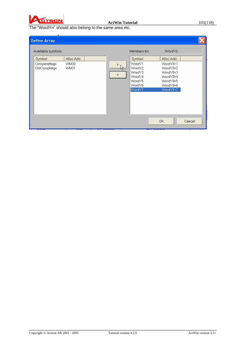
ActWin Tutorial 103(118)
Copyright © Actwin AB 2001 - 2005 Tutorial version 4.2.0 ActWin version 3.5+
The “WordYn” should also belong to the same area etc.

ActWin Tutorial 104(118)
Copyright © Actwin AB 2001 - 2005 Tutorial version 4.2.0 ActWin version 3.5+
Define the physical addresses as Confirm. This will force a popup window when inserting the macro where the user can select addresses depending on module position etc.

ActWin Tutorial 105(118)
Copyright © Actwin AB 2001 - 2005 Tutorial version 4.2.0 ActWin version 3.5+
The total symbol address definition will look like:

ActWin Tutorial 106(118)
Copyright © Actwin AB 2001 - 2005 Tutorial version 4.2.0 ActWin version 3.5+

ActWin Tutorial 107(118)
Copyright © Actwin AB 2001 - 2005 Tutorial version 4.2.0 ActWin version 3.5+
Now the macro is ready: Store the macro in the user library using Copy and Paste. This means that it can be re-used in other projects and you can share the library with other users.

ActWin Tutorial 108(118)
Copyright © Actwin AB 2001 - 2005 Tutorial version 4.2.0 ActWin version 3.5+
How to use the macro in a project If you e.g. want 6 counters (3 EH CU slots) then you will use 3 instances of the macro. Define the hardware configuration.
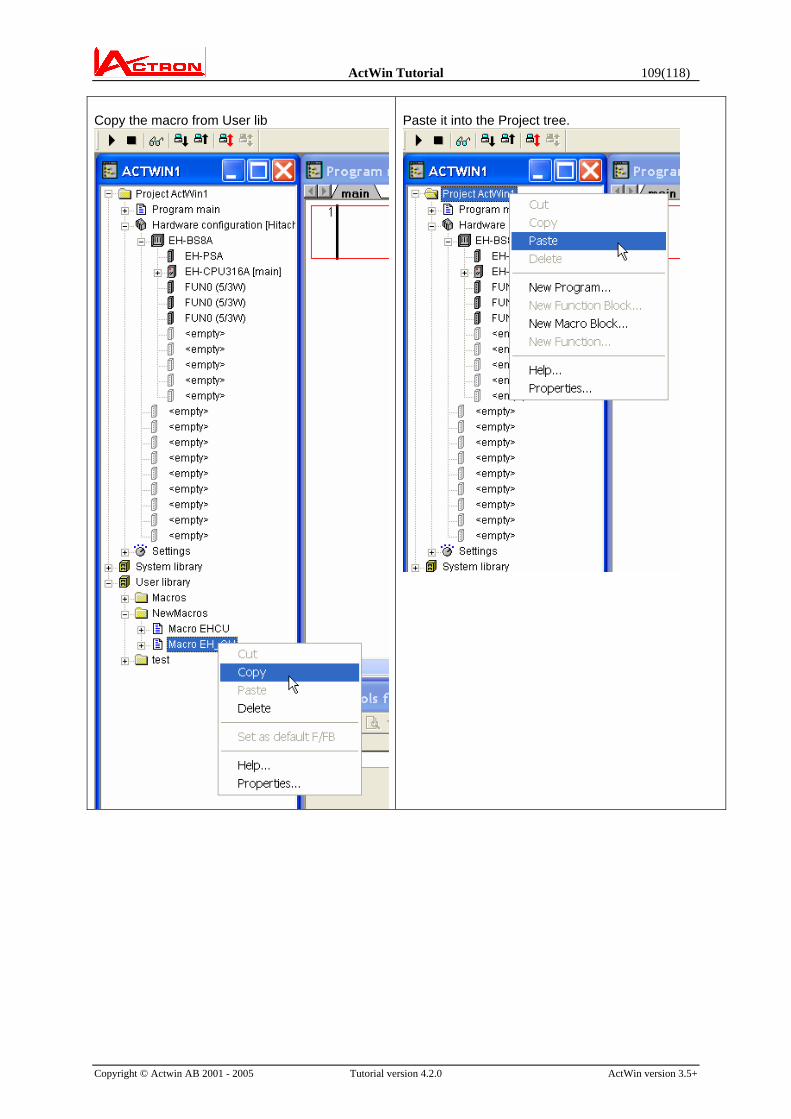
ActWin Tutorial 109(118)
Copyright © Actwin AB 2001 - 2005 Tutorial version 4.2.0 ActWin version 3.5+
Copy the macro from User lib
Paste it into the Project tree.

ActWin Tutorial 110(118)
Copyright © Actwin AB 2001 - 2005 Tutorial version 4.2.0 ActWin version 3.5+
Drag the macro into the program window. ActWin will suggest addresses for the Confirm symbols. You will get an opportunity to modify the address.

ActWin Tutorial 111(118)
Copyright © Actwin AB 2001 - 2005 Tutorial version 4.2.0 ActWin version 3.5+
The macro will now be a part of your ladder diagram.
The Input and Output variables will be accessible on the outside of the macro. Connect the inputs to the symbols you are using in the application program. Booleans can be connected as contacts and coils and the other symbols as well as booleans can be directly connected. Just double click on the line.
For reference, all macro symbols (including Locals) will be listed in the Symbol window.

ActWin Tutorial 112(118)
Copyright © Actwin AB 2001 - 2005 Tutorial version 4.2.0 ActWin version 3.5+

ActWin Tutorial 113(118)
Copyright © Actwin AB 2001 - 2005 Tutorial version 4.2.0 ActWin version 3.5+
When you have connected the first macro, you can insert the second instance. (The macro for the second slot)
Again, ActWin will suggest addresses for the Confirm symbols. You will get an opportunity to modify the address.
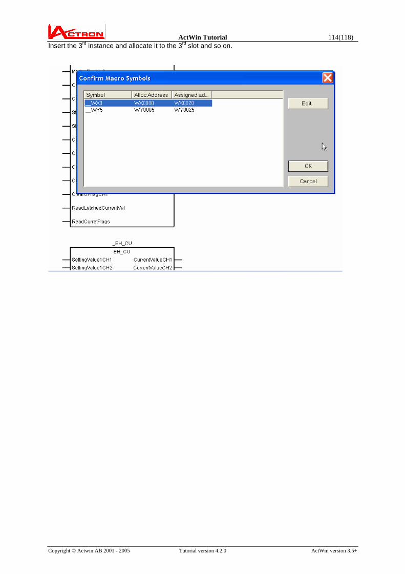
ActWin Tutorial 114(118)
Copyright © Actwin AB 2001 - 2005 Tutorial version 4.2.0 ActWin version 3.5+
Insert the 3rd instance and allocate it to the 3rd slot and so on.

ActWin Tutorial 115(118)
Copyright © Actwin AB 2001 - 2005 Tutorial version 4.2.0 ActWin version 3.5+
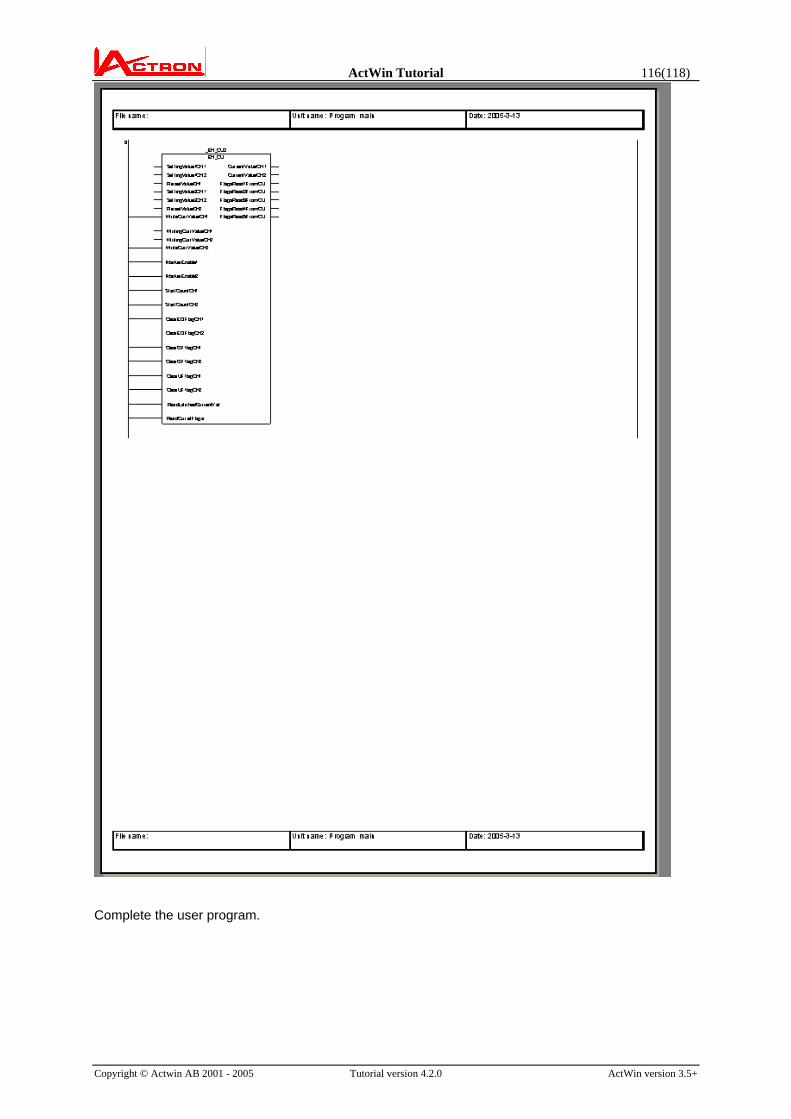
ActWin Tutorial 116(118)
Copyright © Actwin AB 2001 - 2005 Tutorial version 4.2.0 ActWin version 3.5+
Complete the user program.
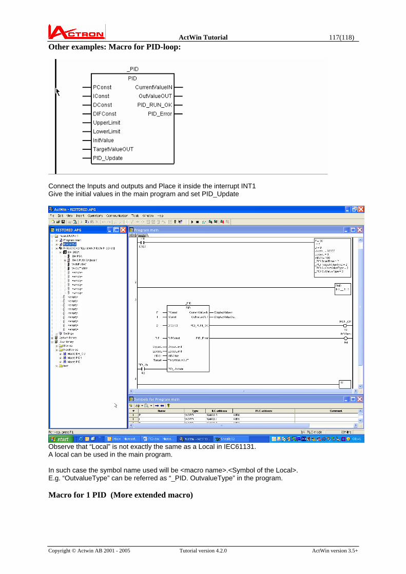
ActWin Tutorial 117(118)
Copyright © Actwin AB 2001 - 2005 Tutorial version 4.2.0 ActWin version 3.5+
Other examples: Macro for PID-loop:
Connect the Inputs and outputs and Place it inside the interrupt INT1 Give the initial values in the main program and set PID_Update
Observe that “Local” is not exactly the same as a Local in IEC61131. A local can be used in the main program. In such case the symbol name used will be <macro name>.<Symbol of the Local>. E.g. “OutvalueType” can be referred as “_PID. OutvalueType” in the program. Macro for 1 PID (More extended macro)

ActWin Tutorial 118(118)
Copyright © Actwin AB 2001 - 2005 Tutorial version 4.2.0 ActWin version 3.5+
Similar macros can be available for more than 1 PID
Note: The programs in this tutorial are meant as examples only and may not be fully featured or completely
tested for usage in an actual application.