actuator line - tech-con.hu · simple shafts, hollow shaft ss-37 accessories ss-38 ordering key...
TRANSCRIPT

Actuator Line
www.rollon.com
General catalogueEnglish
Part 1

When you move. We move
Rollon S.p.A. was set up in 1975 as a manufacturer of linear motion components. Today Rollon group is a
leading name in the design, production and sale of linear rails, telescopic rails and actuators, with headquar-
ters based in Italy and offi ces and distributors located throughout the world. Rollon products are used in many
industries with creative and effi cient solutions in a wide range of applications used on a daily basis.
Solutions for linear motion
Linear Rails Telescopic Rails ActuatorsRails with roller bearings
Rails with caged ball bearings
Rails with recirculating ball bearing
Rails with partial/total extension
Heavy duty rails
Rails for and automated/manual
applications
Belt driven actuators
Ball screw driven actuators
Rack and pinion actuators
Actuator Line
www.rollon.com
EN_Actuator_COVER.indd 1 08/05/2014 10:15:21

Aerospace
Medical Special Vehicles Robotics Packaging
Railway Logistics Industrial
Applications
Core Competencies
Full range of linear rails, telescopic rails and actuators
Worldwide presence with branches and distributors
Fast delivery all over the world
Large technical know-how for applications
Standard solutions Collaboration CustomizationWide range of products and sizes
Linear rails with roller and caged ball
bearings
Heavy duty telescopic rails
Belt or ball screw driven linear actuators
Multi-axis systems
International know-how in several
industries
Project consultancy
Maximizing performance and cost
optimization
Special products
Research and development of new
solutions
Technologies dedicated to different
sectors
Optimal surface trea

Content
Plus SystemTechnical features overview
1 ELM series ELM series description PLS-2
The components PLS-3
The linear motion system PLS-4
ELM 50 SP - ELM 50 CI PLS-5
ELM 65 SP - ELM 65 CI PLS-6
ELM 80 SP - ELM 80 CI PLS-7
ELM 110 SP - ELM 110 CI PLS-8
Lubrication, Planetary gear PLS-9
Simple shaft PLS-10
Hollow shafts PLS-11
Linear units parallel, Accessories PLS-12
Ordering key PLS-14
2 ROBOT series ROBOT series description PLS-15
The components PLS-16
The linear motion system PLS-17
ROBOT 100 SP PLS-18
ROBOT 100 SP-2C PLS-19
ROBOT 100 CE PLS-20
ROBOT 100 CE-2C PLS-21
ROBOT 130 SP PLS-22
ROBOT 130 SP-2C PLS-23
ROBOT 130 CE PLS-24
ROBOT 130 CE-2C PLS-25
ROBOT 160 SP PLS-26
ROBOT 160 SP-2C PLS-27
ROBOT 160 CE PLS-28
ROBOT 160 CE-2C PLS-29
ROBOT 220 SP PLS-30
ROBOT 220 SP-2C PLS-31
Lubrication, Planetary gear PLS-32
Simple shaft PLS-33
Hollow shafts, Accessories PLS-34
Ordering key PLS-39
3 SC series SC series description PLS-40
The components PLS-41
The linear motion system PLS-42
SC 65 SP PLS-43
SC 130 SP PLS-44
SC 160 SP PLS-45
Lubrication, Planetary gear PLS-46
Simple shaft, Hollow shafts PLS-47
Accessories PLS-48
Ordering key PLS-51
Multiaxis systems PLS-52
Plus System
FrontespizioPlusSystem.indd 1 22/11/2014 16:31:32

Clean Room System
Clean Room System
FrontespizioCleanRoomSystem.indd 1 22/11/2014 16:31:12
1 ONE series ONE series description CRS-2
The components CRS-3
The linear motion system CRS-4
ONE 50 CRS-5
ONE 80 CRS-6
ONE 110 CRS-7
Planetary gear CRS-8
Accessories CRS-9
Ordering key CRS-11
Smart System
Smart System
FrontespizioSmartSystem.indd 1 22/11/2014 16:30:42
1 E-SMART series E-SMART series description SS-2
The components SS-3
The linear motion system SS-4
E-SMART 30 SP2 SS-5
E-SMART 50 SP1 - SP2 - SP3 SS-6
E-SMART 80 SP1 - SP2 SS-7
E-SMART 80 SP3 - SP4 SS-8
E-SMART 100 SP1 - SP2 SS-9
E-SMART 100 SP3 - SP4 SS-10
Lubrication SS-11
Simple shafts, Hollow sahft SS-12
Linear units in parallel, Accessories SS-13
Ordering key SS-16
2 R-SMART series R-SMART series description SS-17
The components SS-18
The linear motion system SS-19
R-SMART 120 SP4 - SP6 SS-20
R-SMART 160 SP4 - SP6 SS-21
R-SMART 220 SP4 - SP6 SS-22
Lubrication SS-23
Simple shafts, Hollow shaft SS-24
Accessories SS-25
Ordering key SS-29
3 S-SMART series S-SMART series description SS-30
The components SS-31
The linear motion system SS-32
S-SMART 50 SP SS-33
S-SMART 65 SP SS-34
S-SMART 80 SP SS-35
Lubrication SS-36
Simple shafts, Hollow shaft SS-37
Accessories SS-38
Ordering key SS-41
Multiaxis systems SS-42

Eco System
Eco System
FrontespizioEcoSystem.indd 1 22/11/2014 16:30:23
1 ECO series ECO series description ES-2
The components ES-3
The linear motion system ES-4
ECO 60 SP2 - ECO 60 CI ES-5
ECO 80 SP2 - ECO 80 SP1 - ECO 80 CI ES-6
ECO 100 SP2 - ECO 100 SP1 - ECO 100 CI ES-7
Simple shafts, Hollow shafts ES-8
Linear units in parallel, Accessories ES-9
Ordering key ES-12
Multiaxis systems ES-13
Uniline System1 Uniline A series Uniline A series description US-2
The components US-3
A40 US-4
A55 US-6
A75 US-8
A100 US-10
Lubrication US-14
Accessories US-15
Ordering key US-18
2 Uniline C series Uniline C series description US-20
The components US-21
C55 US-22
C75 US-24
Lubrication US-26
Accessories US-27
Ordering key US-30
3 Uniline E series Uniline E series description US-32
The components US-33
E55 US-34
E75 US-36
Lubrication US-38
Accessories US-39
Ordering key US-42
4 Uniline ED series Uniline ED series description US-44
The components US-45
ED75 US-46
Lubrication US-48
Accessories US-49
Ordering key US-52
5 Uniline H series Uniline H series description US-54
Uniline System
FrontespizioUnilineSystem.indd 1 22/11/2014 16:32:41

Precision System1 TH series TH series description PS-2
The components PS-3
TH 90 SP2 PS-4
TH 90 SP4 PS-5
TH 110 SP2 PS-6
TH 110 SP4 PS-7
TH 145 SP2 PS-8
TH 145 SP4 PS-9
Motor connections PS-10
Lubrication PS-11
Critical speed, Calculation factors PS-12
Accessories PS-14
Ordering key PS-19
2 TT series TT series description PS-20
The components PS-21
TT 100 PS-22
TT 155 PS-24
TT 225 PS-26
TT 310 PS-28
Lubrication PS-30
Accurancy certifi cate PS-31
Critical speed, Calculation factors PS-33
Accessories PS-35
Ordering key PS-38
3 TV series TV series description PS-39
The components PS-40
TV 60 PS-41
TV 80 PS-42
TV 110 PS-43
TV 140 PS-44
Lubrication PS-45
Critical speed, Calculation factors PS-46
Accessories PS-48
Ordering key PS-50
4 TK series TK series description PS-52
The components PS-53
TK 40 PS-54
Precision System
FrontespizioPrecisionSystem.indd 1 22/11/2014 16:31:55
The components US-55
H40 US-56
H55 US-57
H75 US-58
Lubrication US-59
Accessories US-60
Ordering key US-62
6 Belt tension US-63
7 Installation instructions US-65

Static load and service life Plus-Clean Room-Smart-Eco-Precision SL-2
Static load and service life Uniline SL-4
Data sheet SL-9
TK 60 PS-56
TK 80 PS-58
Critical speed PS-60
Ordering key PS-61
Multiaxis systems PS-62


Technical features overview
Reference Section Driving
Anticorrosion Protection
Family Product Balls RollersToothed
belt
Ball
screw
Rack and
pinion
Uniline
SystemA/C/E/ED/H
Eco
SystemECO
Clean Room
SystemONE
Plus
System
ELM
ROBOT
SC
Smart
System
E-SMART
R-SMART
S-SMART
Precision
System
TH
TT
TV
TK
Reported data must be verifi ed according to the application. See verifi cation under static load and lifetime on page SL-2 and SL-7
For a complete overview about technical data, please consult our catalogues at www.rollon.com.
* Longer stroke is available for jointed version

Size
Max. load capacity
per carriage
[N]
Max. static moment
per carriage
[Nm] Max.
travel speed
[m/s]
Max.
acceleration
[m/s²]
Repeatability
accuracy
[mm]
Max. travel
or stroke
(per system)
[mm]F
xF
yF
zM
xM
yM
z
Fz
My
Fy
Fx
Mz
Mx
40-55-75-100 1000 25000 17400 800,4 24917 15752 9 20 ± 0,05 5700*
60-80-100 4070 43400 43400 570 4297 4297 5 50 ± 0,05 6000*
50-80-110 4440 92300 110760 1110 9968 8307 5 50 ± 0,05 6000*
50-65-80-110 4440 79000 79000 1180 7110 7110 5 50 ± 0,05 6000*
100-130-160-220
8510 158000 158000 13588 17696 17696 5 50 ± 0,05 6000*
65-130-160 5957 86800 86800 6770 17577 17577 5 50 ± 0,05 2500
30-50-80-100 4440 87240 87240 1000 5527 5527 4 50 ± 0,05 6000*
120-160-220 8880 237000 237000 20145 30810 30810 4 50 ± 0,05 6000*
50-65-80 2250 51260 51260 520 3742 3742 4 50 ± 0,05 2000
90-110-145 27000 86800 86800 3776 2855 2855 2 ± 0,005 1500
100-155-225-310
58300 230580 274500 30195 26627 22366 2,5 ± 0,005 3000
60-80-110-140
58300 48400 48400 2251 3049 3049 2,5 ± 0,01 4000
40-60-80 12462 50764 50764 1507 622 622 1,48 ± 0,003 810
PLS
CRS
SS
ES
US
PS


Plus System
FrontespizioPlusSystem.indd 1 22/11/2014 16:31:32

PLS-2
ELM series description
1 ELM series
ELM
This is Rollon's highly versatile, premier line of completely enclosed belt
drive linear actuators.
The ELM linear units are available in four sizes from 50 mm to 110 mm.
They have a self-supporting structure with a robust profi le of extruded and
anodized aluminum. The thrust force is transmitted by a steel reinforced,
polyurethane. The moving carriage is precisely guided and supported by a
linear guide system or optional cam roller system.
A polyurethane sealing strip ensures complete protection of the belt drive
and linear guide system against dust, dirt, chips, liquids and other con-
taminants. It avoids the fragility of other sealing systems such as stainless
steel strips.
The components used for linear motion, lubricant reservoir, caged ball
bearing blocks and double-lip seals; promote a "maintenance-free" sys-
tem. The pulleys, bearings and drive shafts are among the most robust in
the industry. ELM is the best product for applications in very aggressive
working environments that also require high speed duty cycles and posi-
tion repeatability.
Corrosion resistant version
All Plus System series of linear actuators are available with stainless steel
elements, for applications in harsh environments and/or subject to fre-
quent washes.
The Plus System linear units are constructed using extruded anodized
6060 and 6082 Anti-Corrosive Aluminum, which houses bearings, linear
rails, nuts and bolts and components made stainless steel, preventing or
delaying corrosion caused by humidity experienced in the environments
where the linear units are used.
Special no-deposit surface treatments are combined with a food grade
lubrication system to allow use in highly sensitive applications, such as
the food and pharmaceutical industries where product contamination
is prohibited.
■ Internal stainless steel elements
■ Anodized 6060 and 6082 Anti-Corrosive Aluminum Profi le
■ AISI 440 stainless steel linear rails
■ Lubricated with organic food grade vegetable oils
Fig. 1
ELM series

PLS-3
Plus System
PLS
The components
Extruded profi le
The anodized 6060 aluminum alloy extrusion used for the profi le of the
Rollon ELM series linear units were designed and manufactured by in-
dustry experts to optimize weight while maintaining mechanical strength.
(see physical-chemical characteristics below).The dimensional tolerances
comply with EN 755-9 standard.
Driving belt
The Rollon ELM series linear units use steel reinforced polyurethane drive
belts with AT pitch. This belt is ideal due to its high load transmission
characteristics, compact size and low noise. Used in conjunction with a
backlash-free pulley, smooth alternating motion can be achieved. Opti-
mization of the maximum belt width/body dimension ratio enables the
following performance characteristics to be achieved:
■ High speed
■ Low noise
■ Low wear
General data about aluminum used: AL 6060
Chemical composition [%]
Physical characteristics
Mechanical characteristics
Carriage
The carriage of the Rollon ELM series linear units are made entirely of
anodized aluminum. Each carriage has mounting holes fi tted with stain-
less steel thread inserts. Rollon offers multiple carriages to accommodate
a vast array of applications. The unique design of the carriage allows for
the sealing strip to pass through the carriage as well as house brush seals
to remove contaminates from the sealing strip.
Sealing strip
Rollon ELM series linear units are equipped with a polyurethane sealing
strip to protect all of the internal components from dust, contaminates,
and other foreign objects. The sealing strip runs the length of the body
and is kept in position by micro-bearings located inside the carriage. This
minimizes frictional resistance as the strip passes through the carriage
while providing maximum protection.
AI Mg Si Fe Mn Zn Cu Impurites
Remainder 0.35-0.60 0.30-0.60 0.30 0.10 0.10 0.10 0.05-0.15
Density Coeff. of
elasticity
Coeff. of thermal expansion
(20°-100°C)
Thermal conductivity
(20°C)
Specifi c heat
(0°-100°C)
Resistivity Melting point
kg___
dm3
kN___
mm2
10-6
___
K
W_____
m . K
J_____
kg . K
Ω . m . 10-9 °C
2.7 69 23 200 880-900 33 600-655
Rm Rp (02) A HB
N___
mm2
N___
mm2
% __
205 165 10 60-80
Tab. 1
Tab. 2
Tab. 3

PLS-4
1 ELM series
The linear motion system
The linear motion system has been designed to meet the load capacity,
speed, and maximum acceleration conditions of a wide variety of applica-
tions. Two linear motion systems are offered:
ELM...SP with ball bearing guides
■ A ball bearing guide with high load capacity is mounted in a dedicated
seat inside the body.
■ The carriage is assembled on two pre-loaded ball bearing blocks.
■ The two ball bearing blocks enable the carriage to withstand loading in
the four main directions.
■ The two blocks have seals on both sides and, if necessary, an addi-
tional scraper can be fi tted for very dusty conditions.
■ The ball bearing carriages of the SP versions are also fi tted with a
retention cage that eliminates "steel-steel" contact between adjacent
revolving parts and prevents misalignment.
■ Lubrication reservoirs (pockets) installed on the front of the ball bear-
ing blocks supply the right amount of grease, thus promoting long
maintenance interval.
The linear motion system described above offers:
■ High speed and acceleration
■ High load capacity
■ High permissible bending moments
■ Low friction
■ Long life
■ Maintenance free (depending on applications)
■ Low noise
ELM...CI with gothic arch bearing guides inside the body
■ Two hardened steel rods (58/60 HRC tolerance h6) are securely in-
serted inside the aluminum body.
■ The carriage is fi tted with four bearing assemblies each having a gothic
arch groove machined into its outer race to run on the steel rods.
■ The four bearings are mounted on steel pins, two of which are eccen-
tric, to allow setting of running clearance and pre-load.
■ To keep the running tracks clean and lubricated, four grease impreg-
nated felt seals, complete with grease reservoirs, are fi tted on the ends
of the carriage.
The linear motion system described above offers:
■ Good positioning accuracy
■ Low noise
■ Maintenance free (depending on applications)
ELM SP section ELM CI section
Fig. 2 Fig. 3

PLS-5
Plus System
PLS
ELM 50 SP - ELM 50 CI
Type
ELM 50 SP ELM 50 CI
Max. useful stroke length [mm] 3700 6000*1
Max. positioning repeatability [mm]*2 ± 0.05 ± 0.05
Max. speed [m/s] 4.0 1.5
Max. acceleration [m/s2] 50 1.5
Type of belt 22 AT 5 22 AT 5
Type of pulley Z 23 Z 23
Pulley pitch diameter [mm] 36.61 36.61
Carriage displacement per pulley turn [mm] 115 115
Carriage weight [kg] 0.4 0.5
Zero travel weight [kg] 1.8 1.7
Weight for 100 mm useful stroke [kg] 0.4 0.3
Starting torque [Nm] 0.4 0.4
Moment of inertia of pulleys [g mm2] 19810 19810
15.5
30.5
70
15.5
75.5
5010
860 .3
1212
26
50
4.2
5050
0701051
803565
108181 26 2662
10150
48
50
50
6.2 4
60
L = 315 + USEFUL STROKE + SAFETY
8xM5 Depth 6
* The length of the safety stroke is provided on request according to the customer's specifi c requirements.
*1) It is possible to obtain strokes up to 9000 mm by means of special Rollon joints
*2) Positioning repeatability is dependent on the type of transmission used
ELM 50 SP - ELM 50 CI Dimension
Technical data
Fig. 4
Tab. 4
Type Fx
[N]
Fy
[N]
Fz
[N]
Mx
[Nm]
My
[Nm]
Mz
[Nm]
Stat. Dyn. Stat. Dyn Stat. Dyn Stat. Dyn Stat. Dyn Stat. Dyn
ELM 50 SP 809 508 7000 4492 7000 4492 42 27 231 148 231 148
ELM 50 CI 809 624 1480 2540 910 1410 16 25 36 55 58 99
ELM 50 - Load capacity
See verifi cation under static load and lifetime on page SL-2 and SL-3 Tab. 7
Type Ix
[107 mm4]
Iy
[107 mm4]
Ip
[107 mm4]
ELM 50 0.025 0.031 0.056
Type Type of
belt
Belt width
[mm]
Weight
kg/m
ELM 50 22 AT 5 22 0.072
Moments of inertia of the aluminum body
Fx
MzFz
Mx
FyMy
Driving belt
The driving belt is manufactured from a friction resistant
polyurethane and with steel cords for high tensile stress
resistance.
Belt length (mm) = 2 x L - 130 (SP and CI Models)
Tab. 5
Tab. 6

PLS-6
1 ELM series
ELM 65 SP - ELM 65 CI
Type
ELM 65 SP ELM 65 CI
Max. useful stroke length [mm]*1 6000 6000
Max. positioning repeatability [mm]*2 ± 0.05 ± 0.05
Max. speed [m/s] 5.0 1.5
Max. acceleration [m/s2] 50 1.5
Type of belt 32 AT 5 32 AT 5
Type of pulley Z 32 Z 32
Pulley pitch diameter [mm] 50.93 50.93
Carriage displacement per pulley turn [mm] 160 160
Carriage weight [kg] 1.1 1.0
Zero travel weight [kg] 3.5 3.3
Weight for 100 mm useful stroke [kg] 0.6 0.5
Starting torque [Nm] 1.5 1.5
Moment of inertia of pulleys [g mm2] 117200 117200
* The length of the safety stroke is provided on request according to the customer's specifi c requirements.
*1) It is possible to obtain strokes up to 11000 mm by means of special Rollon joints
*2) Positioning repeatability is dependent on the type of transmission used
ELM 65 SP - ELM 65 CI Dimension
Technical data
Fig. 5
Tab. 8
Type Fx
[N]
Fy
[N]
Fz
[N]
Mx
[Nm]
My
[Nm]
Mz
[Nm]
Stat. Dyn. Stat. Dyn Stat. Dyn Stat. Dyn Stat. Dyn Stat. Dyn
ELM 65 SP 1344 883 24200 14560 24200 14560 240 138 747 449 747 449
ELM 65 CI 1344 1075 3800 7340 2470 4080 58 96 100 170 160 310
ELM 65 - Load capacity
See verifi cation under static load and lifetime on page SL-2 and SL-3 Tab. 11
Type Ix
[107 mm4]
Iy
[107 mm4]
Ip
[107 mm4]
ELM 65 0.060 0.086 0.146
Type Type of
belt
Belt width
[mm]
Weight
kg/m
ELM 65 32 AT 5 32 0.105
Moments of inertia of the aluminum body
Fx
MzFz
Mx
FyMy
Driving belt
The driving belt is manufactured from a friction resistant
polyurethane and with steel cords for high tensile stress
resistance.
Belt length (mm) = 2 x L - 180 (SP model)
2 x L - 145 (CI model)
Tab. 9
Tab. 10
65
10.
5
6.7
7 4.5 15
3
5
15
65
85 10 80
85
95 42.5
L = 415 + USEFUL STROKE + SAFETY
65
2
0.5
6
5
37.5
35 75 35
37.5
220
8 x M5 Depth 6
45
10 10
64
95.
5
10
65

PLS-7
Plus System
PLS
ELM 80 SP - ELM 80 CI
Type
ELM 80 SP ELM 80 CI
Max. useful stroke length [mm]*1 6000 6000
Max. positioning repeatability [mm]*2 ± 0.05 ± 0.05
Max. speed [m/s] 5.0 1.5
Max. acceleration [m/s2] 50 1.5
Type of belt 32 AT 10 32 AT 10
Type of pulley Z 19 Z 19
Pulley pitch diameter [mm] 60.48 60.48
Carriage displacement per pulley turn [mm] 190 190
Carriage weight [kg] 2.7 2.5
Zero travel weight [kg] 10.5 9.5
Weight for 100 mm useful stroke [kg] 1.0 0.8
Starting torque [Nm] 2.2 2.2
Moment of inertia of pulleys [g mm2] 388075 388075
* The length of the safety stroke is provided on request according to the customer's specifi c requirements.
*1) It is possible to obtain strokes up to 11000 mm by means of special Rollon joints
*2) Positioning repeatability is dependent on the type of transmission used
ELM 80 SP - ELM 80 CI Dimension
Technical data
Fig. 6
Tab. 12
Type Fx
[N]
Fy
[N]
Fz
[N]
Mx
[Nm]
My
[Nm]
Mz
[Nm]
Stat. Dyn. Stat. Dyn Stat. Dyn Stat. Dyn Stat. Dyn Stat. Dyn
ELM 80 SP 2013 1170 43400 34800 43400 34800 570 440 3168 2540 3168 2540
ELM 80 CI 2013 1605 8500 17000 4740 8700 140 250 390 710 700 1390
ELM 80 - Load capacity
See verifi cation under static load and lifetime on page SL-2 and SL-3 Tab. 15
Type Ix
[107 mm4]
Iy
[107 mm4]
Ip
[107 mm4]
ELM 80 0.136 0.195 0.331
Type Type of
belt
Belt width
[mm]
Weight
kg/m
ELM 80 32 AT 10 32 0.185
Moments of inertia of the aluminum body
Fx
MzFz
Mx
FyMy
Driving belt
The driving belt is manufactured from a friction resistant
polyurethane and with steel cords for high tensile stress
resistance.
Belt length (mm) = 2 x L - 230 (SP and CI Models)
Tab. 13
Tab. 14
80
2
6
105
100
L = 540 + USEFUL STROKE + SAFETY
105 15
120 52.5
80
300
49 42 118 42 49
48
8xM6 Depth 8
10 10
78
118
.5
12.
5
80
80
19
4
2
19
8
0
9.5 6
8.2
1
3.2

PLS-8
1 ELM series
ELM 110 SP - ELM 110 CI
Type
ELM 110 SP ELM 110 CI
Max. useful stroke length [mm]*1 6000 6000
Max. positioning repeatability [mm]*2 ± 0.05 ± 0.05
Max. speed [m/s] 5.0 1.5
Max. acceleration [m/s2] 50 1.5
Type of belt 50 AT 10 50 AT 10
Type of pulley Z 27 Z 27
Pulley pitch diameter [mm] 85.94 85.94
Carriage displacement per pulley turn [mm] 270 270
Carriage weight [kg] 5.6 5.1
Zero travel weight [kg] 22.5 21.6
Weight for 100 mm useful stroke [kg] 1.4 1.1
Starting torque [Nm] 3.5 3.5
Moment of inertia of pulleys [g mm2] 2.193·106 2.193·106
* The length of the safety stroke is provided on request according to the customer's specifi c requirements.
*1) It is possible to obtain strokes up to 11000 mm by means of special Rollon joints
*2) Positioning repeatability is dependent on the type of transmission used
ELM 110 SP - ELM 110 CI Dimension
Technical data
Fig. 7
Tab. 16
Type Fx
[N]
Fy
[N]
Fz
[N]
Mx
[Nm]
My
[Nm]
Mz
[Nm]
Stat. Dyn. Stat. Dyn Stat. Dyn Stat. Dyn Stat. Dyn Stat. Dyn
ELM 110 SP 4440 2940 79000 55000 79000 55000 1180 780 7110 4950 7110 4950
ELM 110 CI 4440 3660 19300 41700 12500 24500 330 650 960 1880 1480 3200
ELM 110 - Load capacity
See verifi cation under static load and lifetime on page SL-2 and SL-3 Tab. 19
Type Ix
[107 mm4]
Iy
[107 mm4]
Ip
[107 mm4]
ELM 110 0.446 0.609 1.054
Type Type of
belt
Belt width
[mm]
Weight
kg/m
ELM 110 50 AT 10 50 0.290
Moments of inertia of the aluminum body
Fx
MzFz
Mx
FyMy
Driving belt
The driving belt is manufactured from a friction resistant
polyurethane and with steel cords for high tensile stress
resistance.
Belt length (mm) = 2 x L - 290 (SP and CI Models)
Tab. 17
Tab. 18
110
3
5
135 145 15
145
160
72.5
L = 695 + USEFUL STROKE + SAFETY
110
8xM8 Depth 15 380
60 60 140 60 60
70
10 10
108
162
.5
17.
5
130
110
24
6
2
24
8.5 12
11.
3
18

PLS-9
Plus System
PLS
Tab. 20
Lubrication
SP linear units with ball bearing guides
SP Linear units are equipped with self lubricating linear ball guides.
The ball bearing carriages of the SP versions are also fi tted with a
retention cage that eliminates "steel-steel" contact between adjacent
revolving parts and prevents misalignment of these in the circuits.
Special lubrication reservoirs are mounted on the front plates of the linear
blocks which continuously provide the necessary amount of grease to the
ball raceways under load. These lubrication reservoirs also considerably
reduce the frequency of lubrication of the module. This system guarantees
a long interval between maintenances: SP version: every 5000 km or 1
year of use, based on the value reached fi rst. If a longer service life is
required or in case of high dynamic or high loaded applications please
contact our offi ces for further verifi cation.
CI linear units with gothic arch bearing guides
Linear units with gothic arch bearing guides are equipped with an extended
period lubrication system. Four grease impregnated felt scrapers, complete
with grease reservoirs, guarantee a service life of ca. 6000 km without
relubrication. If relubrication is required to obtain a higher service life
please contact our offi ces.
■ Insert the tip of the grease gun in the specific grease blocks.
■ For lubrication of linear units use lithium soap grease NLGI 2.
■ For specially stressed applications or difficult enviromental
Quantity of lubricant necessary for re-lubrication:
Type Unit: [g]
ELM 50 SP 1
ELM 65 SP 1.6
ELM 80 SP 2.8
ELM 110 SP 5.6
Fig. 8
Planetary gears
Assembly to the right or to the left of the driving head
The series ELM linear units can be fi tted with several different drive
systems. In each case, the driving pulley is attached to the reduction
gearshaft by means of a tapered coupling to ensure high accuracy over a
long period of time.
Fig. 9
Right
Left
Versions with planetary gears
Planetary gears are used for highly dynamic robot, automation and
handling applications involving stressing cycles and with high level
precision requirements. Standard models are available with clearance
from 3' to 15' and with a reduction ratio from 1:3 to 1:1000. For assembly
of non-standard planetary gear, contact our offi ces.
conditions, lubrication should be carried out more frequently.
Apply to Rollon for futher advice.

PLS-10
1 ELM series
Unit Shaft type B D1
ELM 50 AS 12 25 12h7
ELM 65 AS 15 35 15h7
ELM 80 AS 20 40 20h7
ELM 110 AS 25 50 25h7
Simple shaft version
Simple shaft type AS
Position of the simple shaft can be to the right, left, or both sides of the
drive head.Fig. 10
Tab. 22
Tab. 21
Unit Shaft type Head code
AS left
Head code
AS right
Head code
double AS
ELM 50 AS 12 1E 1C 1A
ELM 65 AS 15 1E 1C 1A
ELM 80 AS 20 1E 1C 1A
ELM 110 AS 25 1E 1C 1A
D1
D1 B
B
Unit Head code
AS right + AE
Head code
AS left + AE
ELM 50 VF VG
ELM 65 1G 1I
ELM 80 1G 1I
ELM 110 1G 1I
Simple shaft type AE 10 for encoder assembly + AS
Position of the simple shafts for encoder assembly to the right or to the left
on the drive head.Fig. 11
Tab. 23
4 x M4 8
49
10 8 for ELM 50 20

PLS-11
Plus System
PLS
Unit Shaft
type
D2 D3 M Head code
AS left
Head code
AS right
ELM 50 AS 12 55 70 M5 VQ VP
ELM 65 AS 15 60 85 M6 UQ UP
ELM 80 AS 20 80 100 M8 UN UM
ELM 110 AS 25 110 130 M8 UL UI
Shaft with centering pilot
Fig. 12
Tab. 24
D3
D
2
4 x M
Unit First Second
A B C D
ELM 50 20 10 - -
ELM 65 20 11 14 20
ELM 80 30 20 20 30
ELM 110 45 20.5 33 30
Air Hole
Fig. 13 Tab. 25
A
B
G1/4
FIRST OPTION C
D
G1/4
SECOND OPTION
Hollow shafts
AC hollow shaft type
Fig. 14
Appliable
to unit
Shaft type Head code
ELM 50 AC 12 2A
ELM 80 AC 19 2A
ELM 110 AC 25 2A
ELM 110 AC 32 2C
Tab. 26
Appliable
to unit
Shaft type D1 D2 D3 E F Keyway B x H
ELM 50 AC 12 12H7 60 75 3.5 M5 4 x 4
ELM 80* AC 19 19H7 80 100 3.5 M6 6 x 6
ELM 110 AC 25 25H7 110 130 4.5 M8 8 x 7
ELM 110 AC 32 32H7 130 165 4.5 M10 10 x 8
Dimensions (mm)
An (optional) connection fl ange is required to fi t the standard reduction units
selected by Rollon. For further information contact our offi ces
Rollon can provide driving heads with output shaft, centering diameter and
threads.
* Dimensions of head change (see detail "A" Fig. 14) Tab. 27
D1D3
4 x F Keyway BxH
E
D2
134
92
Detail "for ELM 80"

PLS-12
1 ELM series
Linear units in parallel
Synchronization kit for use of ELM linear units in parallel
When movement consisting of two linear units in parallel is essential, a
synchronization kit must be used. This consists of original Rollon lamina
type precision joints complete with tapered splines and hollow aluminum
drive shafts.
Fig. 15
D
8 L
D
9
D
7
Appliable
to unit
Shaft type D7 D8 D9 Code Formula for length
calculation
ELM 50 AP 12 12 25 45 GK12P...1A L= X-68 [mm]
ELM 65 AP 15 15 40 69.5 GK15P...1A L= X-74 [mm]
ELM 80 AP 20 20 40 69.5 GK20P...1A L= X-97 [mm]
ELM 110 AP 25 25 70 99 GK25P...1A L= X-165 [mm]
Dimensions (mm)
Fig. 16
Tab. 28
Accessories
Fixing by brackets
The linear motion systems used for the Rollon series ELM linear units
enables them to support loads in any direction. They can therefore be
installed in any position.
To install the units, we recommend the use of the dedicated T-slots in the
extruded bodies as shown below.
Warning:
Do not fi x the linear units through the drive ends.Fig. 17
Unit A
(mm)
ELM 50 62
ELM 65 77
ELM 80 94
ELM 110 130
Tab. 29
A
X

PLS-13
Plus System
PLS
Fixing brackets
T-Nuts
Fig. 18
Fig. 19
Fixing bracket
Anodized aluminum block for fi xing the linear units through the side T-slots of the body.
T-nuts
Steel nuts to be used in the T-slots of the body.
Unit A H1 B C E F D1 D2 L L1 Code
ELM 50 20 14 6 16 10 6 10 5.5 35 17.5 1000958
ELM 65 20 17.5 6 16 11.5 6 9.4 5.3 50 25 1001490
ELM 80 20 20.7 7 16 14.7 7 11 6.4 50 25 1001491
ELM 110 36.5 28.5 10 31 18.5 11.5 16.5 10.5 100 50 1001233
Unit D3 D4 G H2 K Code
ELM 50 - M4 - 3.4 8 1001046
ELM 65 6.7 M5 2.3 6.5 10 1000627
ELM 80 8 M6 3.3 8.3 13 1000043
ELM 110 11 M8 2.8 10.8 17 1000932
Dimensions (mm)
Dimensions (mm)
Tab. 30
Tab. 31
LØ D1
Ø D4
Ø D3
Ø D2
H1
H2
G
E
F
A
CB
L1
K
Proximity ELM...SP - ELM...CI series
Dimensions (mm)
Sensor proximity housing kit
Red anodized aluminum sensor holder, equipped with T-nuts for
fi xing onto the profi le.
Sensor dog
L-shaped bracket in zinc-plated iron, mounted on the carriage
and used for proximity switch operations.
Tab. 32
Fig. 20
Unit B4 B5 L4 L5 H4 H5 For
proximity
Sensor dog
code
Sensor proximity
housing kit code
ELM 50 9.5 14 25 29 11.9 22.5 Ø 8 G000268 G000211
ELM 65 17.2 20 50 40 17 32 Ø 12 G000267 G000212
ELM 80 17.2 20 50 40 17 32 Ø 12 G000267 G000209
ELM 110 17.2 20 50 40 17 32 Ø 12 G000267 G000210
L4 L5
Sensor dogSensor proximityhousing kit
B5
H5
H
4
B4
Sensor proximityhousing kit
Sensor dog

PLS-14
Ordering key
Ordering key
Identifi cation codes for the ELM linear unit
E 06
05=50
06=65
08=80
11=110
1C 2000 1A
1A=SP
1C=CI
D
Multiple carriage
Linear motion system see pg. PLS-4
L = total length of the unit
Driving head code see pg. PLS-10 - PLS-11
Linear unit size see from pg. PLS-5 to pg. PLS-8
ELM Series see pg. PLS-2
In order to create identifi cation codes for Actuator Line, you can visit: http://confi gureactuator.rollon.com

PLS-15
Plus System
PLS
ROBOT series description
ROBOT
The ROBOT series is particularly well-suited for heavy load applications
where signifi cant carriage pitch, yaw or roll moments are applied; or for
the linear conveyance of SCARA-type articulated arm robots on a transfer
or factory automation line. As a robust, high load choice, the ROBOT Se-
ries is the linear actuator for the most demanding applications.
Available in four sizes from 100 mm to 220 mm, the ROBOT series linear
units have a rigid structure made by a heavy rectangular cross-section
of extruded and anodized aluminum. The thrust force is transmitted by
a steel reinforced polyurethane. The carriage is running on two paral-
lel linear guides with four self-lubricated "maintenance-free" caged ball
bearing blocks, positioned to support the carriage and all incident loads
and moments. Multiple independent or idler style carriages are available
to further enhance load or moment carrying capacity.
A polyurethane sealing strip ensures complete protection of the driving
belt against dirt, chips, liquids and other contaminants.
The ROBOT series is the clear choice for heavy, high-speed, fl uctuating
load and moment applications in aggressive environments where repeat-
able, maintenance-free industrial automation is required.
For every size of ROBOT series is available also the 2C version, with
2 independent carriages. Each carriage is driven by its own belt. The
driving head can accomodate two gearboxes, one on each side. This solu-
tion is ideal for pick & place application or loading and unloading machine.
Corrosion resistant version
All Plus System series of linear actuators are available with stainless steel
elements, for applications in harsh environments and/or subject to fre-
quent washes.
The Plus System linear units are constructed using extruded anodized
6060 and 6082 Anti-Corrosive Aluminum, which houses bearings, linear
rails, nuts and bolts and components made of stainless steel, preventing
or delaying corrosion caused by humidity experienced in the environments
where the linear units are used.
Special no-deposit surface treatments are combined with a food grade
lubrication system to allow use in highly sensitive applications, such as
the food and pharmaceutical industries where product contamination is
prohibited.
■ Internal stainless steel elements
■ Anodized 6060 and 6082 Anti-Corrosive Aluminum Profi le
■ AISI 440 stainless steel linear rails
■ Lubricated with organic food grade vegetable oils
Fig. 21
ROBOT series

PLS-16
The components
Extruded profi le
The anodized 6060 aluminum alloy extrusion used for the profi le of
the Rollon ROBOT series linear units were designed and manufactured
by industry experts to optimize weight while maintaining mechanical
strength. The dimensional tolerances comply with EN 755-9 standards.
T-slots are provided in the side and bottom faces to facilitate mounting.
Driving belt
The Rollon ROBOT series linear units use steel reinforced polyurethane
drive belts with AT pitch. This belt is ideal due to its high load transmis-
sion characteristics, compact size and low noise. Used in conjunction with
backlash-free pulleys, smooth alternating motion can be achieved. Op-
timization of the maximum belt width/body dimension ratio enables the
following performance characteristics to be achieved:
■ High speed
■ Low noise
■ Low wear
The provision of guidance for the belt within the body causes it to run
central on the pulley, there by ensuring long service life.
Carriage
The carriage of the Rollon ROBOT series linear units are made entirely of
anodized aluminum. Each carriage has mounting holes fi tted with stain-
less steel thread inserts. Rollon offers multiple carriages to accommodate
a vast array of applications. The unique design of the carriage allows for
the sealing strip to pass through the carriage as well as house brush seals
to remove contaminates from the sealing strip.
Sealing strip
Rollon ROBOT series linear units are equipped with a polyurethane sealing
strip to protect all of the internal components from dust, contaminates,
and other foreign objects. The sealing strip runs the length of the body and
is kept in posi-tion by micro-bearings located with in the carriage. This
minimizes frictional resistance as the strip passes through the carriage
while providing maximum protection.
General data about aluminum used: AL 6060
Chemical composition [%]
Physical characteristics
Mechanical characteristics
AI Mg Si Fe Mn Zn Cu Impurites
Remainder 0.35-0.60 0.30-0.60 0.30 0.10 0.10 0.10 0.05-0.15
Density Coeff. of
elasticity
Coeff. of thermal expansion
(20°-100°C)
Thermal conductivity
(20°C)
Specifi c heat
(0°-100°C)
Resistivity Melting point
kg___
dm3
kN___
mm2
10-6
___
K
W_____
m . K
J_____
kg . K
Ω . m . 10-9 °C
2.7 69 23 200 880-900 33 600-655
Rm Rp (02) A HB
N___
mm2
N___
mm2
% __
205 165 10 60-80
Tab. 33
Tab. 34
Tab. 35
2 ROBOT series

PLS-17
Plus System
PLS
The linear motion system
The linear motion system has been designed to meet the load capacity,
speed, and maximum acceleration conditions of a wide variety of applica-
tions. Two linear motion systems are offered:
ROBOT ...SP with ball bearing guides
■ Two ball bearing guides with high load capacity are mounted in two
dedicated seats on the outer sides of the body.
■ The carriage is assembled on four pre-loaded ball bearing blocks.
■ The four ball row confi guration enable the carriage to withstand load-
ing in the four main directions.
■ The four blocks have seals on both sides and, if necessary, an ad-
ditional scraper can be fi tted for very dusty conditions.
■ The ball bearing carriages of the SP versions are also fi tted with a
retention cage that eliminates "steel-steel" contact between adjacent
revolving parts and prevents misalignment.
■ The lubrication reservoirs (pockets) fi tted on the cages considerably
decreases re-lubrication frequency. Lubrication reservoirs (pockets)
installed on the front of the ball bearing blocks supply the right amount
of grease, thus promoting long maintenance interval.
The linear motion system described above offers:
■ High speed and acceleration
■ High load capacity
■ High bending permissible moments
■ Low friction
■ Long duration
■ Maintenance free (dependent on application, see page PLS-32
"Lubrication")
■ Low noise
ROBOT CE with gothic arch bearing guides
■ Two hardened steel rods (58/60 HRC hardness, tolerance: h6) are
securely inserted into the aluminum body.
■ The carriage is fi tted with four bearing assemblies, each having a
gothic arch groove machined into its outer race to run on the steel
rods.
■ The four bearings are mounted on steel pins, of which are eccentric to
allow the running clearance and preload to be set.
■ To keep the running tracks clean and lubricated, four grease impreg-
nated felt seals, complete with grease reservoirs, are fi tted at the ends.
The linear motion system described above offers:
■ Good positioning accuracy
■ Low noise
■ Maintenance free (dependant on application)
ROBOT SP section ROBOT CE section
Fig. 22 Fig. 23
ROBOT 2C
For both the SP an CE linear motion system is available the 2C version,
which features 2 independent carriages on a single actuator.

PLS-18
ROBOT 100 SP
* The length of the safety stroke is provided on request according to the customer's specifi c requirements.
ROBOT 100 SP dimensions
Fig. 24
4040
6xM5 DEPTH 6
GREASE NIPPLES
9010
90
100
65
80
1018010
115
28 124 28
100
115
100
55 6.2
12 76 128.3 4.2 4
15.5
8
81.5 33
.5
27.5
27.5
4545
4545
L = 365 + USEFUL STROKE + SAFETY
2 ROBOT series
Type
ROBOT 100 SP
Max. useful stroke length [mm] 5800
Max. positioning repeatability [mm]*1 ± 0.05
Max. speed [m/s] 4.0
Max. acceleration [m/s2] 50
Type of belt 32 AT 5
Type of pulley Z 23
Pulley pitch diameter [mm] 36.61
Carriage displacement per pulley turn [mm] 115
Carriage weight [kg] 2.4
Zero travel weight [kg] 4.5
Weight for 100 mm useful stroke [kg] 0.8
Starting torque [Nm] 1.3
Moment of inertia of pulleys [g mm2] 87200
*1) Positioning repeatability is dependent on the type of transmission used
Technical data
Tab. 36
Type Fx
[N]
Fy
[N]
Fz
[N]
Mx
[Nm]
My
[Nm]
Mz
[Nm]
Stat. Dyn. Stat. Dyn Stat. Dyn Stat. Dyn Stat. Dyn Stat. Dyn
ROBOT 100 SP 1176 739 25040 16800 25040 16800 851 571 1452 974 1452 974
ROBOT 100 SP - Load capacity
See verifi cation under static load and lifetime on page SL-2 and SL-3 Tab. 39
Type Ix
[107 mm4]
Iy
[107 mm4]
Ip
[107 mm4]
ROBOT 100 0.05 0.23 0.28
Type Type of
belt
Belt width
[mm]
Weight
kg/m
ROBOT 100 SP 32 AT 5 32 0.105
Moments of inertia of the aluminum body
Fx
MzFz
Mx
FyMy
Driving belt
The driving belt is manufactured from a friction resistant
polyurethane and with steel cords for high tensile stress
resistance.
Belt length (mm) = 2 x L - 115
Tab. 37
Tab. 38

PLS-19
Plus System
PLS
ROBOT 100 SP-2C
* The length of the safety stroke is provided on request according to the customer's specifi c requirements.
ROBOT 100 SP-2C dimensions
Fig. 25
Type
ROBOT 100 SP-2C
Max. useful stroke length [mm] 5600
Max. positioning repeatability [mm]*1 ± 0.05
Max. speed [m/s] 4.0
Max. acceleration [m/s2] 50
Type of belt 16 AT 5
Type of pulley Z 23
Pulley pitch diameter [mm] 36.61
Carriage displacement per pulley turn [mm] 115
Carriage weight [kg] 2.4
Zero travel weight [kg] 8.0
Weight for 100 mm useful stroke [kg] 0.8
Starting torque [Nm] 1.3
Moment of inertia of pulleys [g mm2] 16220
*1) Positioning repeatability is dependent on the type of transmission used
Technical data
Tab. 40
Type Fx
[N]
Fy
[N]
Fz
[N]
Mx
[Nm]
My
[Nm]
Mz
[Nm]
Stat. Dyn. Stat. Dyn Stat. Dyn Stat. Dyn Stat. Dyn Stat. Dyn
ROBOT 100 SP-2C 588 370 25040 16800 25040 16800 851 571 1452 974 1452 974
ROBOT 100 SP-2C - Load capacity
See verifi cation under static load and lifetime on page SL-2 and SL-3 Tab. 43
Type Ix
[107 mm4]
Iy
[107 mm4]
Ip
[107 mm4]
ROBOT 100 0.05 0.23 0.28
Type Type of
belt
Belt width
[mm]
Weight
kg/m
ROBOT 100 SP-2C 16 AT 5 16 0.05
Moments of inertia of the aluminum body
Fx
MzFz
Mx
FyMy
Driving belt
The driving belt is manufactured from a friction resistant
polyurethane and with steel cords for high tensile stress
resistance.
Belt length (mm) = 2 x L - 115
Tab. 41
Tab. 42
4040
4040
6xM5 DEPTH 6 6xM5 DEPTH 6
GREASE NIPPLES
9010
90
100
65
100
10 180 10 180 10
28 124 28 28 124 28
80
27.5
27.5
4545
45 45
115
100
55 6.2
12 76 128.3 4.2 4
15.5
8
115
81.5 33
.5L = 555 + USEFUL STROKE + SAFETY

PLS-20
2 ROBOT series
ROBOT 100 CE
* The length of the safety stroke is provided on request according to the customer's specifi c requirements.
ROBOT 100 CE dimensions
Fig. 26
Type
ROBOT 100 CE
Max. useful stroke length [mm] 6000
Max. positioning repeatability [mm]*1 ± 0.05
Max. speed [m/s] 1.5
Max. acceleration [m/s2] 1.5
Type of belt 32 AT 5
Type of pulley Z 23
Pulley pitch diameter [mm] 36.61
Carriage displacement per pulley turn [mm] 115
Carriage weight [kg] 3.4
Zero travel weight [kg] 5.5
Weight for 100 mm useful stroke [kg] 0.8
Starting torque [Nm] 1.3
Moment of inertia of pulleys [g mm2] 87200
*1) Positioning repeatability is dependent on the type of transmission used
Technical data
Tab. 44
Type Fx
[N]
Fy
[N]
Fz
[N]
Mx
[Nm]
My
[Nm]
Mz
[Nm]
Stat. Dyn. Stat. Dyn Stat. Dyn Stat. Dyn Stat. Dyn Stat. Dyn
ROBOT 100 CE 1176 907 3800 7340 2460 4080 120 198 160 265 250 477
ROBOT 100 CE - Load capacity
See verifi cation under static load and lifetime on page SL-2 and SL-3 Tab. 47
Type Ix
[107 mm4]
Iy
[107 mm4]
Ip
[107 mm4]
ROBOT 100 0.05 0.23 0.28
Type Type of
belt
Belt width
[mm]
Weight
kg/m
ROBOT 100-CE 32 AT 5 32 0.105
Moments of inertia of the aluminum body
Fx
MzFz
Mx
FyMy
Driving belt
The driving belt is manufactured from a friction resistant
polyurethane and with steel cords for high tensile stress
resistance.
Belt length (mm) = 2 x L - 115
Tab. 45
Tab. 46
52.5
52.5
6xM5 DEPTH 8
103
90
100
9010
80100
65
1018010
165
28 124 28
165
100
5512 76 12
4.28.36.
2
415
.5
8052
.527
.527
.5
45 45
4545
L = 365 + USEFUL STROKE + SAFETY

PLS-21
Plus System
PLS
ROBOT 100 CE-2C
* The length of the safety stroke is provided on request according to the customer's specifi c requirements.
ROBOT 100 CE-2C dimensions
Fig. 27
Type
ROBOT 100 CE-2C
Max. useful stroke length [mm] 5800
Max. positioning repeatability [mm]*1 ± 0.05
Max. speed [m/s] 1.5
Max. acceleration [m/s2] 1.5
Type of belt 16 AT 5
Type of pulley Z 23
Pulley pitch diameter [mm] 36.61
Carriage displacement per pulley turn [mm] 115
Carriage weight [kg] 3.4
Zero travel weight [kg] 10.5
Weight for 100 mm useful stroke [kg] 0.8
Starting torque [Nm] 1.3
Moment of inertia of pulleys [g mm2] 16220
*1) Positioning repeatability is dependent on the type of transmission used
Technical data
Tab. 48
Type Fx
[N]
Fy
[N]
Fz
[N]
Mx
[Nm]
My
[Nm]
Mz
[Nm]
Stat. Dyn. Stat. Dyn Stat. Dyn Stat. Dyn Stat. Dyn Stat. Dyn
ROBOT 100 CE-2C 588 454 3800 7340 2460 4080 120 198 160 265 250 477
ROBOT 100 CE-2C - Load capacity
See verifi cation under static load and lifetime on page SL-2 and SL-3 Tab. 51
Type Ix
[107 mm4]
Iy
[107 mm4]
Ip
[107 mm4]
ROBOT 100 0.05 0.23 0.28
Type Type of
belt
Belt width
[mm]
Weight
kg/m
ROBOT 100 CE-2C 16 AT 5 16 0.05
Moments of inertia of the aluminum body
Fx
MzFz
Mx
FyMy
Driving belt
The driving belt is manufactured from a friction resistant
polyurethane and with steel cords for high tensile stress
resistance.
Belt length (mm) = 2 x L - 115
Tab. 49
Tab. 50
6xM5 DEPTH 8
52.5
52.5
6xM5 DEPTH 8
52.5
52.5
103
9010
90
100
65
100
10 180 10 180 10
28 124 28 28 124 28
80
27.5
27.5
45 45
4545
165
8052
.5
165
100
55
12 76 124.28.3
6.2
415
.5
L = 555 + USEFUL STROKE + SAFETY
PLS-22
2 ROBOT series
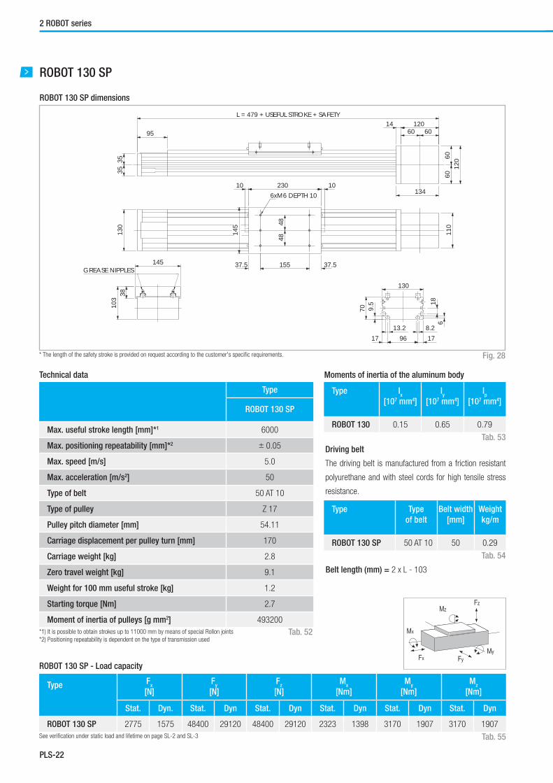
ROBOT 130 SP
* The length of the safety stroke is provided on request according to the customer's specifi c requirements.
ROBOT 130 SP dimensions
Fig. 28
Type
ROBOT 130 SP
Max. useful stroke length [mm]*1 6000
Max. positioning repeatability [mm]*2 ± 0.05
Max. speed [m/s] 5.0
Max. acceleration [m/s2] 50
Type of belt 50 AT 10
Type of pulley Z 17
Pulley pitch diameter [mm] 54.11
Carriage displacement per pulley turn [mm] 170
Carriage weight [kg] 2.8
Zero travel weight [kg] 9.1
Weight for 100 mm useful stroke [kg] 1.2
Starting torque [Nm] 2.7
Moment of inertia of pulleys [g mm2] 493200
*1) It is possible to obtain strokes up to 11000 mm by means of special Rollon joints
*2) Positioning repeatability is dependent on the type of transmission used
Technical data
Tab. 52
Type Fx
[N]
Fy
[N]
Fz
[N]
Mx
[Nm]
My
[Nm]
Mz
[Nm]
Stat. Dyn. Stat. Dyn Stat. Dyn Stat. Dyn Stat. Dyn Stat. Dyn
ROBOT 130 SP 2775 1575 48400 29120 48400 29120 2323 1398 3170 1907 3170 1907
ROBOT 130 SP - Load capacity
See verifi cation under static load and lifetime on page SL-2 and SL-3 Tab. 55
Type Ix
[107 mm4]
Iy
[107 mm4]
Ip
[107 mm4]
ROBOT 130 0.15 0.65 0.79
Type Type
of belt
Belt width
[mm]
Weight
kg/m
ROBOT 130 SP 50 AT 10 50 0.29
Moments of inertia of the aluminum body
Fx
MzFz
Mx
FyMy
Driving belt
The driving belt is manufactured from a friction resistant
polyurethane and with steel cords for high tensile stress
resistance.
Belt length (mm) = 2 x L - 103
Tab. 53
Tab. 54
4848
6xM6 DEPTH 10
37.5 37.5155
12014
120
134
95
110
1023010
145
130
145
130
70 9.5
13.2 8.217 96 17
61810
338
3535
60 60
6060
GREASE NIPPLES
L = 479 + USEFUL STROKE + SAFETY

PLS-23
Plus System
PLS
ROBOT 130 SP-2C
* The length of the safety stroke is provided on request according to the customer's specifi c requirements.
ROBOT 130 SP-2C dimensions
Fig. 29
Type
ROBOT 130 SP-2C
Max. useful stroke length [mm]*1 6000
Max. positioning repeatability [mm]*2 ± 0.05
Max. speed [m/s] 5.0
Max. acceleration [m/s2] 50
Type of belt 25 AT 10
Type of pulley Z 17
Pulley pitch diameter [mm] 54.11
Carriage displacement per pulley turn [mm] 170
Carriage weight [kg] 2.8
Zero travel weight [kg] 14.9
Weight for 100 mm useful stroke [kg] 1.2
Starting torque [Nm] 2.7
Moment of inertia of pulleys [g mm2] 196200
*1) It is possible to obtain strokes up to 11000 mm by means of special Rollon joints
*2) Positioning repeatability is dependent on the type of transmission used
Technical data
Tab. 56
Type Fx
[N]
Fy
[N]
Fz
[N]
Mx
[Nm]
My
[Nm]
Mz
[Nm]
Stat. Dyn. Stat. Dyn Stat. Dyn Stat. Dyn Stat. Dyn Stat. Dyn
ROBOT 130 SP-2C 1388 788 48400 29120 48400 29120 2323 1398 3170 1907 3170 1907
ROBOT 130 SP-2C - Load capacity
See verifi cation under static load and lifetime on page SL-2 and SL-3 Tab. 59
Type Ix
[107 mm4]
Iy
[107 mm4]
Ip
[107 mm4]
ROBOT 130 0.15 0.65 0.79
Type Type of
belt
Belt width
[mm]
Weight
kg/m
ROBOT 130 SP-2C 25 AT 10 25 0.16
Moments of inertia of the aluminum body
Fx
MzFz
Mx
FyMy
Driving belt
The driving belt is manufactured from a friction resistant
polyurethane and with steel cords for high tensile stress
resistance.
Belt length (mm) = 2 x L - 103
Tab. 57
Tab. 58
10 230 10 230 10
4848
6xM6 DEPTH 10
4848
6xM6 DEPTH 10
37.537.5 37.5
37.5155 155
14 120
120
134
95
130
110
145
3535
60 60
6060
ROBOT 130 NTS 2C
145
103
38
130
70 9.5
13.2 8.217 96 17
618
GREASE NIPPLES
L = 719 + USEFUL STROKE + SAFETY

PLS-24
2 ROBOT series
ROBOT 130 CE
* The length of the safety stroke is provided on request according to the customer's specifi c requirements.
ROBOT 130 CE dimensions
Fig. 30
Type
ROBOT 130 CE
Max. useful stroke length [mm]*1 6000
Max. positioning repeatability [mm]*2 ± 0.05
Max. speed [m/s] 1.5
Max. acceleration [m/s2] 1.5
Type of belt 50 AT 10
Type of pulley Z 17
Pulley pitch diameter [mm] 54.11
Carriage displacement per pulley turn [mm] 170
Carriage weight [kg] 4.3
Zero travel weight [kg] 10.3
Weight for 100 mm useful stroke [kg] 1.1
Starting torque [Nm] 2.7
Moment of inertia of pulleys [g mm2] 493200
*1) It is possible to obtain strokes up to 11000 mm by means of special Rollon joints
*2) Positioning repeatability is dependent on the type of transmission used
Technical data
Tab. 60
Type Fx
[N]
Fy
[N]
Fz
[N]
Mx
[Nm]
My
[Nm]
Mz
[Nm]
Stat. Dyn. Stat. Dyn Stat. Dyn Stat. Dyn Stat. Dyn Stat. Dyn
ROBOT 130 CE 2775 2138 3800 17000 4760 8700 300 548 392 724 704 1410
ROBOT 130 CE - Load capacity
See verifi cation under static load and lifetime on page SL-2 and SL-3 Tab. 63
Type Ix
[107 mm4]
Iy
[107 mm4]
Ip
[107 mm4]
ROBOT 130 0.15 0.65 0.79
Type Type of
belt
Belt width
[mm]
Weight
kg/m
ROBOT 130 CE 50 AT 10 50 0.29
Moments of inertia of the aluminum body
Fx
MzFz
Mx
FyMy
Driving belt
The driving belt is manufactured from a friction resistant
polyurethane and with steel cords for high tensile stress
resistance.
Belt length (mm) = 2 x L - 103
Tab. 61
Tab. 62
4050
40
32.5 32.5165
8xM8 DEPTH 16
136
120
12014
134
95
110
1023010
220
130
3535
60 60
6060
130
70 9.5
17 96 1713.2 8.2 6
18
220
96 55.5
L = 479 + USEFUL STROKE + SAFETY

PLS-25
Plus System
PLS
ROBOT 130 CE-2C
* The length of the safety stroke is provided on request according to the customer's specifi c requirements.
ROBOT 130 CE-2C dimensions
Fig. 31
Type
ROBOT 130 CE-2C
Max. useful stroke length [mm]*1 6000
Max. positioning repeatability [mm]*2 ± 0.05
Max. speed [m/s] 1.5
Max. acceleration [m/s2] 1.5
Type of belt 25 AT 10
Type of pulley Z 17
Pulley pitch diameter [mm] 54.11
Carriage displacement per pulley turn [mm] 170
Carriage weight [kg] 4.3
Zero travel weight [kg] 17.4
Weight for 100 mm useful stroke [kg] 1.1
Starting torque [Nm] 2.7
Moment of inertia of pulleys [g mm2] 196200
*1) It is possible to obtain strokes up to 11000 mm by means of special Rollon joints
*2) Positioning repeatability is dependent on the type of transmission used
Technical data
Tab. 64
Type Fx
[N]
Fy
[N]
Fz
[N]
Mx
[Nm]
My
[Nm]
Mz
[Nm]
Stat. Dyn. Stat. Dyn Stat. Dyn Stat. Dyn Stat. Dyn Stat. Dyn
ROBOT 130 CE-2C 1388 1069 3800 17000 4760 8700 300 548 392 724 704 1410
ROBOT 130 CE-2C - Load capacity
See verifi cation under static load and lifetime on page SL-2 and SL-3 Tab. 67
Type Ix
[107 mm4]
Iy
[107 mm4]
Ip
[107 mm4]
ROBOT 130 0.15 0.65 0.79
Type Type of
belt
Belt width
[mm]
Weight
kg/m
ROBOT 130 CE-2C 25 AT 10 25 0.16
Moments of inertia of the aluminum body
Fx
MzFz
Mx
FyMy
Driving belt
The driving belt is manufactured from a friction resistant
polyurethane and with steel cords for high tensile stress
resistance.
Belt length (mm) = 2 x L - 103
Tab. 65
Tab. 66
L = 719 + USEFUL STROKE + SAFETY
8xM8 DEPTH 16
4050
40
32.532.5
165
8xM8 DEPTH 16
4050
40
32.532.5165
10 230 230 1010
136130
70 9.5
17 96 1713.2 8.2 6
18
220
120
12014
134
95
110
220
130
96 55.5
3535
60 60
6060
PLS-26
2 ROBOT series
Type
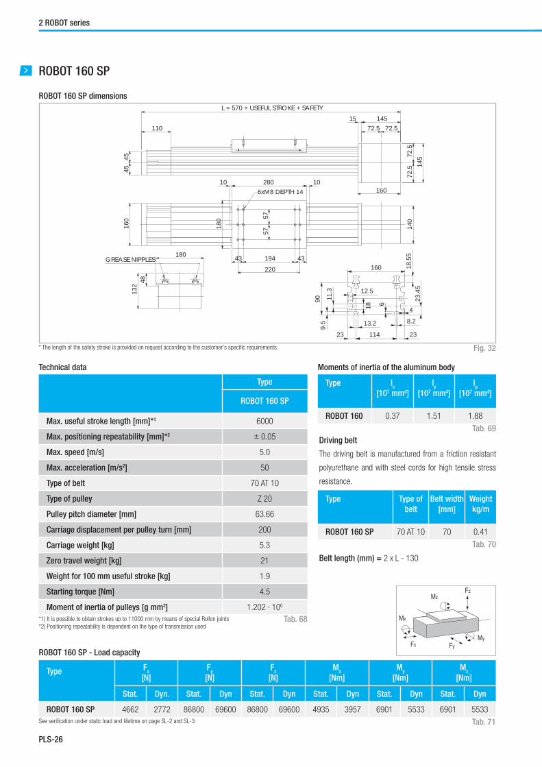
ROBOT 160 SP
Max. useful stroke length [mm]*1 6000
Max. positioning repeatability [mm]*2 ± 0.05
Max. speed [m/s] 5.0
Max. acceleration [m/s2] 50
Type of belt 70 AT 10
Type of pulley Z 20
Pulley pitch diameter [mm] 63.66
Carriage displacement per pulley turn [mm] 200
Carriage weight [kg] 5.3
Zero travel weight [kg] 21
Weight for 100 mm useful stroke [kg] 1.9
Starting torque [Nm] 4.5
Moment of inertia of pulleys [g mm2] 1.202 · 106
*1) It is possible to obtain strokes up to 11000 mm by means of special Rollon joints
*2) Positioning repeatability is dependent on the type of transmission used
Technical data
Tab. 68
Type Fx
[N]
Fy
[N]
Fz
[N]
Mx
[Nm]
My
[Nm]
Mz
[Nm]
Stat. Dyn. Stat. Dyn Stat. Dyn Stat. Dyn Stat. Dyn Stat. Dyn
ROBOT 160 SP 4662 2772 86800 69600 86800 69600 4935 3957 6901 5533 6901 5533
ROBOT 160 SP - Load capacity
See verifi cation under static load and lifetime on page SL-2 and SL-3 Tab. 71
Type Ix
[107 mm4]
Iy
[107 mm4]
Ip
[107 mm4]
ROBOT 160 0.37 1.51 1.88
Type Type of
belt
Belt width
[mm]
Weight
kg/m
ROBOT 160 SP 70 AT 10 70 0.41
Moments of inertia of the aluminum body
Fx
MzFz
Mx
FyMy
Driving belt
The driving belt is manufactured from a friction resistant
polyurethane and with steel cords for high tensile stress
resistance.
Belt length (mm) = 2 x L - 130
Tab. 69
Tab. 70
ROBOT 160 SP
* The length of the safety stroke is provided on request according to the customer's specifi c requirements.
ROBOT 160 SP dimensions
Fig. 32
6xM8 DEPTH 14
5757
180
145
14515
160
110
140
160
1028010
180
43 194
220
43
132 48
4545
72.572.5
72.5
72.5
160
909.
5
23 114 23
13.2 8.2
23.4
5
11.3
18
12.5
4
6
18.5
5
GREASE NIPPLES
L = 570 + USEFUL STROKE + SAFETY

PLS-27
Plus System
PLS
Type
ROBOT 160 SP-2C
Max. useful stroke length [mm]*1 6000
Max. positioning repeatability [mm]*2 ± 0.05
Max. speed [m/s] 5.0
Max. acceleration [m/s2] 50
Type of belt 32 AT 10
Type of pulley Z 19
Pulley pitch diameter [mm] 60.48
Carriage displacement per pulley turn [mm] 190
Carriage weight [kg] 5.3
Zero travel weight [kg] 21
Weight for 100 mm useful stroke [kg] 1.9
Starting torque [Nm] 4.5
Moment of inertia of pulleys [g mm2] 210300
*1) It is possible to obtain strokes up to 11000 mm by means of special Rollon joints
*2) Positioning repeatability is dependent on the type of transmission used
Technical data
Tab. 72
Type Fx
[N]
Fy
[N]
Fz
[N]
Mx
[Nm]
My
[Nm]
Mz
[Nm]
Stat. Dyn. Stat. Dyn Stat. Dyn Stat. Dyn Stat. Dyn Stat. Dyn
ROBOT 160 SP-2C 2013 1170 86800 69600 86800 69600 4935 3957 6901 5533 6901 5533
ROBOT 160 SP - Load capacity
See verifi cation under static load and lifetime on page SL-2 and SL-3 Tab. 75
Type Ix
[107 mm4]
Iy
[107 mm4]
Ip
[107 mm4]
ROBOT 160 0.37 1.51 1.88
Type Type of
belt
Belt width
[mm]
Weight
kg/m
ROBOT 160 SP-2C 32 AT 10 32 0.185
Moments of inertia of the aluminum body
Fx
MzFz
Mx
FyMy
Driving belt
The driving belt is manufactured from a friction resistant
polyurethane and with steel cords for high tensile stress
resistance.
Belt length (mm) = 2 x L - 130
Tab. 73
Tab. 74
ROBOT 160 SP-2C
* The length of the safety stroke is provided on request according to the customer's specifi c requirements.
ROBOT 160 SP-2C dimensions
Fig. 33
57 575757
11015 145
160
43 194220 220
43 43 194 43
145
140
160
10 280 10 280 10
4545
72.5 72.5
72.5
72.5
180
132
48
180
160
909.
5
23 114 23
13.2 8.2
23.4
5
11.3
18
12.5
4
6
18.5
5
GREASE NIPPLES
L = 860 + USEFUL STROKE + SAFETY
6xM8 DEPTH 14 6xM8 DEPTH 14
ATTUATORI_EN.indb PS_27ATTUATORI_EN.indb PS_27 13/04/2015 21:34:2713/04/2015 21:34:27

PLS-28
2 ROBOT series
Type
ROBOT 160 CE
Max. useful stroke length [mm]*1 6000
Max. positioning repeatability [mm]*2 ± 0.05
Max. speed [m/s] 1.5
Max. acceleration [m/s2] 1.5
Type of belt 70 AT 10
Type of pulley Z 20
Pulley pitch diameter [mm] 63.66
Carriage displacement per pulley turn [mm] 200
Carriage weight [kg] 8.6
Zero travel weight [kg] 23
Weight for 100 mm useful stroke [kg] 2.2
Starting torque [Nm] 4.5
Moment of inertia of pulleys [g mm2] 1.202 · 106
*1) It is possible to obtain strokes up to 11000 mm by means of special Rollon joints
*2) Positioning repeatability is dependent on the type of transmission used
Technical data
Tab. 76
Type Fx
[N]
Fy
[N]
Fz
[N]
Mx
[Nm]
My
[Nm]
Mz
[Nm]
Stat. Dyn. Stat. Dyn Stat. Dyn Stat. Dyn Stat. Dyn Stat. Dyn
ROBOT 160 CE 4662 3717 15800 33600 7600 15300 580 1170 820 1650 1710 3630
ROBOT 160 CE - Load capacity
See verifi cation under static load and lifetime on page SL-2 and SL-3 Tab. 79
Type Ix
[107 mm4]
Iy
[107 mm4]
Ip
[107 mm4]
ROBOT 160 0.37 1.51 1.88
Type Type of
belt
Belt width
[mm]
Weight
kg/m
ROBOT 160 CE 70 AT 10 70 0.41
Moments of inertia of the aluminum body
Fx
MzFz
Mx
FyMy
Driving belt
The driving belt is manufactured from a friction resistant
polyurethane and with steel cords for high tensile stress
resistance.
Belt length (mm) = 2 x L - 130
Tab. 77
Tab. 78
ROBOT 160 CE
* The length of the safety stroke is provided on request according to the customer's specifi c requirements.
ROBOT 160 CE dimensions
Fig. 34
8xM8 DEPTH 16
5050
8050
50
145
14515
160
110
140
1028010
280
160
280
6912
1
43 194 43
4545
72.572.5
72.5
72.5
160169
909.
523 114 23
13.2 8.2
23.4
5
418
12.511.3
6
L = 570 + USEFUL STROKE + SAFETY
PLS-29
Plus System
PLS
Type
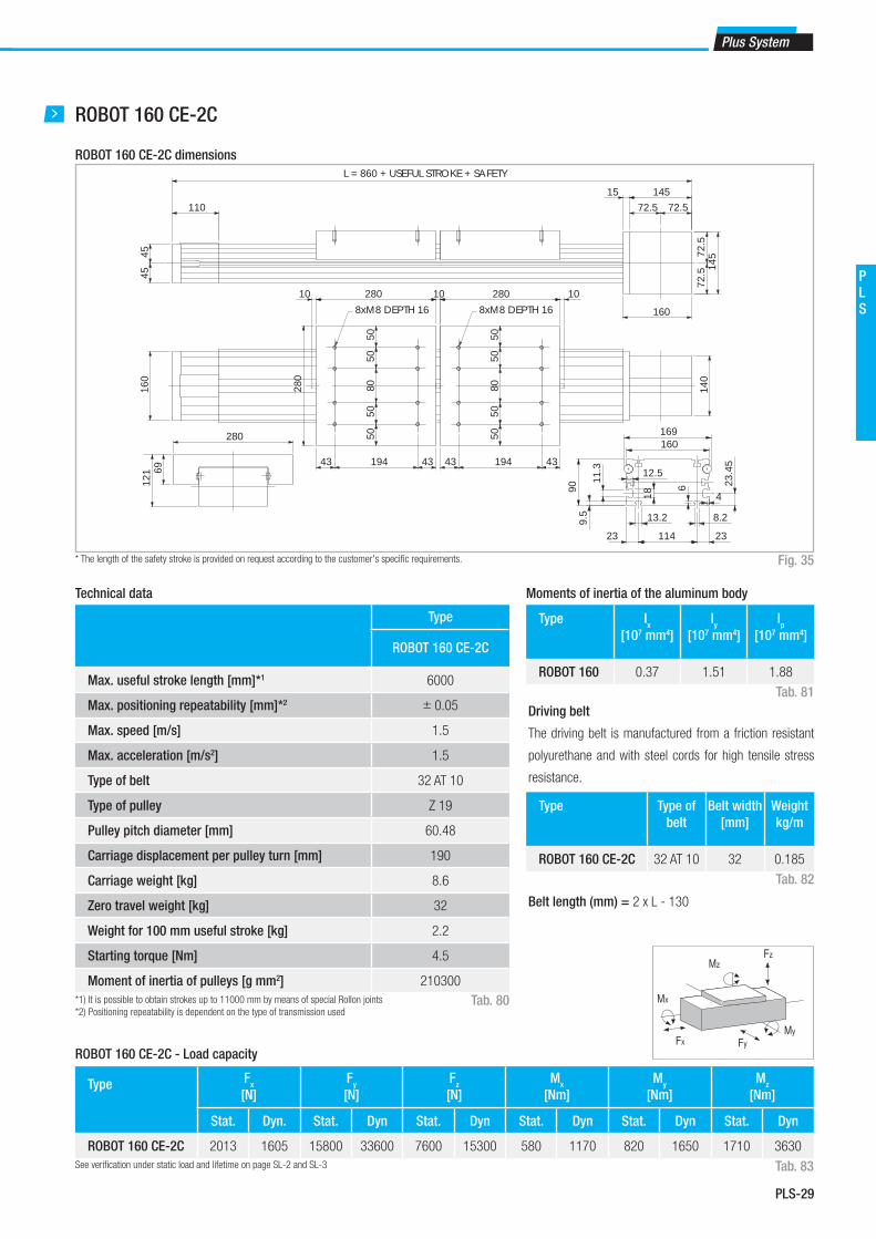
ROBOT 160 CE-2C
Max. useful stroke length [mm]*1 6000
Max. positioning repeatability [mm]*2 ± 0.05
Max. speed [m/s] 1.5
Max. acceleration [m/s2] 1.5
Type of belt 32 AT 10
Type of pulley Z 19
Pulley pitch diameter [mm] 60.48
Carriage displacement per pulley turn [mm] 190
Carriage weight [kg] 8.6
Zero travel weight [kg] 32
Weight for 100 mm useful stroke [kg] 2.2
Starting torque [Nm] 4.5
Moment of inertia of pulleys [g mm2] 210300
*1) It is possible to obtain strokes up to 11000 mm by means of special Rollon joints
*2) Positioning repeatability is dependent on the type of transmission used
Technical data
Tab. 80
Type Fx
[N]
Fy
[N]
Fz
[N]
Mx
[Nm]
My
[Nm]
Mz
[Nm]
Stat. Dyn. Stat. Dyn Stat. Dyn Stat. Dyn Stat. Dyn Stat. Dyn
ROBOT 160 CE-2C 2013 1605 15800 33600 7600 15300 580 1170 820 1650 1710 3630
ROBOT 160 CE-2C - Load capacity
See verifi cation under static load and lifetime on page SL-2 and SL-3 Tab. 83
Type Ix
[107 mm4]
Iy
[107 mm4]
Ip
[107 mm4]
ROBOT 160 0.37 1.51 1.88
Type Type of
belt
Belt width
[mm]
Weight
kg/m
ROBOT 160 CE-2C 32 AT 10 32 0.185
Moments of inertia of the aluminum body
Fx
MzFz
Mx
FyMy
Driving belt
The driving belt is manufactured from a friction resistant
polyurethane and with steel cords for high tensile stress
resistance.
Belt length (mm) = 2 x L - 130
Tab. 81
Tab. 82
ROBOT 160 CE-2C
* The length of the safety stroke is provided on request according to the customer's specifi c requirements.
ROBOT 160 CE-2C dimensions
Fig. 35
8xM8 DEPTH 16 8xM8 DEPTH 16
5050
8050
50
5050
8050
50
145
14515
160
110
140
1028010
160
43 194 43 43 194 43
280 10
4545
72.572.5
72.5
72.5
280
6912
1
280
160169
909.
5
23 114 23
13.2 8.2
23.4
5
418
12.511.3
6
L = 860 + USEFUL STROKE + SAFETY

PLS-30
2 ROBOT series
Type
ROBOT 220 SP
Max. useful stroke length [mm]*1 6000
Max. positioning repeatability [mm]*2 ± 0.05
Max. speed [m/s] 5.0
Max. acceleration [m/s2] 50
Type of belt 100 AT 10
Type of pulley Z 25
Pulley pitch diameter [mm] 79.58
Carriage displacement per pulley turn [mm] 250
Carriage weight [kg] 14.4
Zero travel weight [kg] 41
Weight for 100 mm useful stroke [kg] 2.5
Starting torque [Nm] 6.4
Moment of inertia of each pulley [g mm2] 4.114 · 106
*1) It is possible to obtain strokes up to 11000 mm by means of special Rollon joints
*2) Positioning repeatability is dependent on the type of transmission used
Technical data
Tab. 84
Type Fx
[N]
Fy
[N]
Fz
[N]
Mx
[Nm]
My
[Nm]
Mz
[Nm]
Stat. Dyn. Stat. Dyn Stat. Dyn Stat. Dyn Stat. Dyn Stat. Dyn
ROBOT 220 SP 8510 5520 158000 110000 158000 110000 13588 9460 17696 12320 17696 12320
ROBOT 220 SP - Load capacity
See verifi cation under static load and lifetime on page SL-2 and SL-3 Tab. 87
Type Ix
[107 mm4]
Iy
[107 mm4]
Ip
[107 mm4]
ROBOT 220 0.65 3.26 3.92
Type Type of
belt
Belt width
[mm]
Weight
kg/m
ROBOT 220 SP 100 AT 10 100 0.58
Moments of inertia of the aluminum body
Fx
MzFz
Mx
FyMy
Driving belt
The driving belt is manufactured from a friction resistant
polyurethane and with steel cords for high tensile stress
resistance.
Belt length (mm) = 2 x L - 120
Tab. 85
Tab. 86
ROBOT 220 SP
* The length of the safety stroke is provided on request according to the customer's specifi c requirements.
ROBOT 220 SP dimensions
Fig. 36
5660
56
8xM10 DEPTH 16
5224
242016
11.318
3.512
245
2417224
220
14515
160
145
130
1038010
245
55 270 55
220
170
10015
561
5050
72.5
72.5
72.5 72.5
GREASE NIPPLES
L = 690 + USEFUL STROKE + SAFETY

PLS-31
Plus System
PLS
Type
ROBOT 220 SP-2C
Max. useful stroke length [mm]*1 6000
Max. positioning repeatability [mm]*2 ± 0.05
Max. speed [m/s] 5.0
Max. acceleration [m/s2] 50
Type of belt 40 AT 10
Type of pulley Z 25
Pulley pitch diameter [mm] 79.58
Carriage displacement per pulley turn [mm] 250
Carriage weight [kg] 13.3
Zero travel weight [kg] 46
Weight for 100 mm useful stroke [kg] 2.5
Starting torque [Nm] 6.4
Moment of inertia of pulleys [g mm2] 2.026 · 106
*1) It is possible to obtain strokes up to 11000 mm by means of special Rollon joints
*2) Positioning repeatability is dependent on the type of transmission used
Technical data
Tab. 88
Type Fx
[N]
Fy
[N]
Fz
[N]
Mx
[Nm]
My
[Nm]
Mz
[Nm]
Stat. Dyn. Stat. Dyn Stat. Dyn Stat. Dyn Stat. Dyn Stat. Dyn
ROBOT 220 SP-2C 3404 2208 158000 110000 158000 110000 13588 9460 17696 12320 17696 12320
ROBOT 220 SP-2C - Load capacity
See verifi cation under static load and lifetime on page SL-2 and SL-3 Tab. 91
Type Ix
[107 mm4]
Iy
[107 mm4]
Ip
[107 mm4]
ROBOT 220 0.65 3.26 3.92
Type Type of
belt
Belt width
[mm]
Weight
kg/m
ROBOT 220 SP-2C 40 AT 10 40 0.23
Moments of inertia of the aluminum body
Fx
MzFz
Mx
FyMy
Driving belt
The driving belt is manufactured from a friction resistant
polyurethane and with steel cords for high tensile stress
resistance.
Belt length (mm) = 2 x L - 120
Tab. 89
Tab. 90
ROBOT 220 SP-2C
* The length of the safety stroke is provided on request according to the customer's specifi c requirements.
ROBOT 220 SP-2C dimensions
Fig. 37
5224
242016
5660
56
8xM10 DEPTH 16 8xM10 DEPTH 16
5660
56
13014515
160
145
10 380 10 380 10
220
55 270 55 55 270 55
170
5050
72.5 72.5
72.5
72.5
245
155
61
11.318
3.512
2417224
220
100
245
GREASE NIPPLES
L = 1080 + USEFUL STROKE + SAFETY
ATTUATORI_EN.indb PS_31ATTUATORI_EN.indb PS_31 13/04/2015 21:34:2713/04/2015 21:34:27

PLS-32
2 ROBOT series
Lubrication
SP linear units with ball bearing guides
SP Linear units are equipped with self lubricating linear ball guides.
The ball bearing carriages of the SP versions are also fi tted with a
retention cage that eliminates "steel-steel" contact between adjacent
revolving parts and prevents misalignment of these in the circuits.
Special lubrication reservoirs are mounted on the front plates of the linear
blocks which continuously provide the necessary amount of grease to the
ball raceways under load. These lubrication reservoirs also considerably
reduce the frequency of lubrication of the module. This system guarantees
a long interval between maintenances: SP version: every 5000 km or 1
year of use, based on the value reached fi rst. If a longer service life is
required or in case of high dynamic or high loaded applications please
contact our offi ces for further verifi cation.
Linear units type CE with gothic arch bearing guides
Linear units with gothic arch bearing guides are equipped with along
period lubrication system. Four grease impregnated felt scrapers, complete
with grease reservoirs, guarantee a service life of ca. 6000 km without
relubrication. If relubrication is required to obtain a higher service life
please contact our offi ces.
Tab. 92
■ Insert grease gun in the specifi c grease nipples.
■ Type of lubricant: Lithium soap grease of class NLGI 2.
■ For specially stressed applications or diffi cult environemental condi-
Quantity of lubricant necessary for re-lubrication for each block:
Type Unit: [g]
ROBOT 100 SP 1
ROBOT 130 SP 0.8
ROBOT 160 SP 1.4
ROBOT 220 SP 2.8
Fig. 38
Planetary gears
Assembly to the right or to the left of the driving head
The series Robot linear units can be fi tted with several different drive sys-
tems. In each case, the driving pulley is attached to the reduction gear-
shaft by means of a tapered coupling to ensure high accuracy over a long
period of time.
Right
Left
Versions with planetary gears
Planetary gears are used for highly dynamic robot, automation and han-
dling applications involving stressing cycles and with high level precision
requirements. Standard models are available with clearance from 3' to
15' and with a reduction ratio from 1:3 to 1:1000. For assembly of non-
standard planetary gear, contact our offi ces.
tions, lubrication should be carried out more frequently.
Apply to Rollon for further advice.
Fig. 39
ØD2
ØD3
H

PLS-33
Plus System
PLS
Unit A B Head code
AS right
+ AE
Head code
AS left
+ AE
ROBOT 100 4xM4 Ø49 1G 1I
ROBOT 130 4xM4 Ø79 1G 1I
ROBOT 160 4xM4 Ø76 1G 1I
ROBOT 220 4xM4 Ø76 1G 1I
Simple shaft version
Simple shaft type AS
Simple shaft type AE 10 for encoder assembly + AS
Position of the simple shaft can be to the right, left, or both sides of the
drive head.
Position of the simple shafts for encoder assembly to the right or to the
left on the driving head.
Fig. 40
Fig. 41
Tab. 94
Tab. 95
BB
D1
D1
10
20
B
A
Unit Shaft type Head code
AS left
Head code
AS right
Head code
double AS
ROBOT 100 AS 15 1E 1C 1A
ROBOT 130 AS 20 1E 1C 1A
ROBOT 160 AS 25 1E 1C 1A
ROBOT 220 AS 25 1E 1C 1A
Unit Shaft type B D1
ROBOT 100 AS 15 35 15h7
ROBOT 130 AS 20 40 20h7
ROBOT 160 AS 25 50 25h7
ROBOT 220 AS 25 50 25h7
Tab. 93

PLS-34
2 ROBOT series
Appliable
to unit
Shaft type D1 D2 D3 E F Keyway
B x H
Head
code
ROBOT 100 AC19 19H7 80 100 3 M6 6 x 6 2A
ROBOT 130 AC19 19H7 80 100 4.5 M6 6 x 6 2A
ROBOT 130 AC20 20H7 80 100 4.5 M6 6 x 6 2C
ROBOT 130 AC25 25H7 110 130 4.5 M8 8 x 7 2E
ROBOT 160 AC25 25H7 110 130 4.5 M8 8 x 7 2A
ROBOT 160 AC32 32H7 130 165 4.5 M10 10 x 8 2C
ROBOT 220 AC25 25H7 110 130 4.5 M8 8 x 7 2A
ROBOT 220 AC32 32H7 130 165 4.5 M10 10 x 8 2C
Hollow shafts
AC hollow shaft type
Unit mm
An (optional) connection fl ange is required to fi t the standard reduction
units selected by Rollon.
For further informations contact our offi ces
Fig. 42
Tab. 96
D2
E
D3
N° 4XFKEYWAY BxH
D1
Accessories
Fixing by brackets
The linear motion systems used for the Rollon series ROBOT linear units
enable support of loads in any direction. They can therefore be installed
in any position.
To install the units, we recommend the use of the dedicated T-slots in the
extruded bodies as shown below.
Fig. 43
A Unit A
(mm)
ROBOT 100 112
ROBOT 130 144
ROBOT 160 180
ROBOT 220 240
Tab. 97

PLS-35
Plus System
PLS
Fixing by T-nutsFixing brackets
Warning:
Do not fi x the linear units through the drive ends.
Anodised aluminum block for fixing the linear units through the side
T-slots of the body.
Unit A B C E F D1 D2 H1 L L1 Code
ROBOT 100 20 6 16 10 5.5 9.5 5.3 14 35 17.5 1000958
ROBOT 130 20 7 16 12.7 7 10.5 6.5 18.7 50 25 1001001
ROBOT 160 36.5 10 31 18.5 10.5 16.5 10.5 28.5 100 50 1001233
ROBOT 220 36.5 10 31 18.5 10.5 16.5 10.5 28.5 100 50 1001233
Dimensions (mm)
Fig. 45Fig. 44
Tab. 98
A
D1
F
H1B
D2
C
E
L
L1
C
LI I
L
C
T-nuts
L=Side / C=Central / I=Lower - see fi g. 45
Steel nuts to be used in the slots of the body.
Unit D3 D4 G H2 K Code
ROBOT 100 L-I - M4 - 3.4 8 1001046
ROBOT 130 C - M3 - 4 6 1001097
ROBOT 130 L-I 8 M6 3.3 8.3 13 1000043
ROBOT 160 C - M6 - 5.8 13 1000910
ROBOT 160 I 8 M6 3.3 8.3 13 1000043
ROBOT 160 L 11 M8 2.8 10.8 17 1000932
ROBOT 220 L-I 11 M8 2.8 10.8 17 1000932
Dimensions (mm)
Fig. 46
Tab. 99
K
D4
H2
D3
G

PLS-36
Proximity ROBOT...SPSensor proximity housing kit
Red anodized aluminum sensor holder, equipped with T-nuts for fi xing into
the body slots.
Sensor dog
L-shaped bracket in zinc-plated iron, mounted on the carriage and used
for proximity switch operations.
Fig. 47
Unit B4 B5 L4 L5 H4 H5 For
proximity
Sensor dog
code
Sensor proximity
housing kit code
ROBOT SP 100 9.5 20 25 45 12 25 Ø 8 G000268 G000092
ROBOT SP 130 21 28 50 60 20 40 Ø 12 G000269 G000126
ROBOT SP 160 21 28 50 64 20 40 Ø 12 G000269 G000123
ROBOT SP 220 21 28 50 70 20 40 Ø 12 G000269 G000207
Dimensions (mm)
Tab. 100
PORTA PROXIMITYPATTINO PER PROXIMITYPATTINO PER PROXIMITY
PORTA PROXIMITY
B4
H4H5
B5 L4 L5
Sensor dog Sensor proximityhousing kit
Sensor proximityhousing kit
Sensor dog
Warning:
If a bellow is used, it is not possible to assemble the proximity switch
holders to the aluminum body.
2 ROBOT series
Fig. 48
Unit B4 B5 L4 L5 H4 H5 For
proximity
Sensor dog
code
Sensor proximity
housing kit code
ROBOT CE 100 9.5 47 25 29 12 20 Ø 8 G000268 G000756
ROBOT CE 130 21 57 50 40 20 25 Ø 12 G000269 G000125
ROBOT CE 160 21 57 50 40 20 28.5 Ø 12 G000269 G000124
Dimensions (mm)
Tab. 101
PORTA PROXIMITY
PATTINO PER PROXIMITYPATTINO PER PROXIMITY
PORTA PROXIMITY
H5 H4
B5
B4
L4 L5
Sensor dogSensor dog
Sensor proximityhousing kit
Sensor proximityhousing kit
Warning:
If a bellow is used, it is not possible to assemble the proximity switch
holders to the aluminum body.
Sensor proximity housing kit
Red anodized aluminum sensor holder, equipped with T-nuts for fi xing into
the body slots.
Sensor dog
L-shaped bracket in zinc-plated iron, mounted on the carriage and used
for proximity switch operations.
Proximity ROBOT...CE

PLS-37
Plus System
PLS
Unit A C D E F
ROBOT 130 174 103 95 230 135
ROBOT 160 204 131.5 110 280 160
ROBOT 220 275 149.5 130 380 160
Protections
Dimensions (mm)
Standard protections
The Rollon series ROBOT linear units are equipped with a polyurethane
sealing strip to protect all parts inside the body against dust and foreign
matter. The sealing strip runs the length of the body and is kept in posi-
tion by micro-bearings located within the carriage. This ensures very low
frictional resistance as it passes through the carriage.
Protection of ball bearing guides
The four ball bearing blocks have seals on both sides and, where neces-
sary, an additional scraper can be fi tted for very dusty conditions.
Special protection
To use these linear units in very critical environments, they can be fi tted
with a bellows system in addition to the standard protection. The bellows
is fi xed to the carriage and the ends of the body with Velcro tape for easy
assembly and disassembly.
The total length (L) of the linear unit will vary:
See Fig. 49.
Standard material: Thermally welded nylon coated with polyurethane
Materials on demand: Nylon coated with PVC, fi berglass, stainless steel
Warning: The use of bellows does not allow the assembly of the proximity
switch holders to the aluminum body.
Tab. 102
Fig. 49
D PA E PCH F A
C
L = D + E + F + 2(PCH + 5) + Useful stroke
CE carriage
SP carriage
AP

PLS-38
2 ROBOT series
Kit Code X No rail
at each end (mm)
ROBOT 100 - ELM 65 G000205 75
ROBOT 100 - ROBOT 130 G000201 140
ROBOT 100 - ECO 80 G000203 90
ROBOT 100 - E-SMART 50 G000642 60
ROBOT 130 - ELM 65 G000196 75
ROBOT 130 - ELM 80 G000195 90
ROBOT 130 - ROBOT 130 G000197 140
ROBOT 130 - ROBOT 160 G000198 170
ROBOT 160 - ELM 80 G000204 90
ROBOT 160 - ELM 110 G000452 120
ROBOT 160 - ROBOT 160 G000202 170
ROBOT 160 - ROBOT 220 G000202 230
ROBOT 220 - ELM 110 G000199 120
Tab. 103
Fig. 51Fig. 50
Assembly kits
For the direct assembly of Robot linear units on other types of actuators Rollon offers dedicated assembly kits (brackets) in order to fi x those brackets the
ends of the actuator must be free of rails. The table below gives the codes of the assembly kit. The allowed combination of assembly as well as the lenght
without rails at each end.

PLS-39
Plus System
PLS
R 13
10=100
13=130
16=160
22=220
1C 2000 1A
1A=SP
1E=CE
-075 D
Multiple carriage
ROBOT
on ELM
075 ROBOT 130 - ELM 65 090 ROBOT 130 - ELM 80
075 ROBOT 100 - ELM 65 120 ROBOT 130 - ELM 110
120 ROBOT 130 - ELM 110 see pg. PLS-38
Linear motion system see pg. PLS-17
L = total length of the unit
Driving head code see pg. PLS-33 - PLS-34
Linear unit size see from pg. PLS-18 to pg. PLS-31
Linear unit serie ROBOT see pg. PLS-15
Identifi cation codes for the ROBOT linear unit
Ordering key
In order to create identifi cation codes for Actuator Line, you can visit: http://confi gureactuator.rollon.com

PLS-40
SC series description
SC
The SC series linear units are specifi cally designed for vertical motion in
gantry applications, or in applications where the aluminum profi le must
move while the carriage remains fi xed.
Available in three sizes: 65 mm, 130 mm and 160 mm, the SC linear
actuator has a self-supporting structure made by a profi le (square profi le
for SC 65) of extruded and anodized aluminum.
The SC is a very stiff vertical system, guaranteed by the use of two parallel
linear guides, four "maintenance-free" caged ball bearing blocks and a
very wide belt drive.
The SC Series has been designed for heavy loads and high cycle ap-
plications. It is specifi cally designed and confi gured to be compatible and
assembled with the ROBOT Series actuators without the need for adaptor
plates.
Fig. 52
SC series
3 SC series
Corrosion resistant version
All Plus System series of linear actuators are available with stainless
steel elements, for applications in harsh environments and/or subject
to frequent washes.
The Plus System linear units are constructed using extruded anodized
6060 and 6082 Anti-Corrosive Aluminum, which houses bearings, linear
rails, nuts and bolts and components, all of which are made of low car-
bon SS AISI 303 and 404C steel, to prevent or delay corrosion caused
by humidity experienced in the environments where the linear units are
used.
Special no-deposit surface treatments are combined with a food grade
lubrication system to allow use in highly sensitive applications, such as
the food and pharmaceutical industries where product contamination
is prohibited.
■ Internal stainless steel elements
■ Anodized 6060 and 6082 Anti-Corrosive Aluminum Profi le
■ Very low carbon SS AISI 303 and 404C steel linear rails, nuts and
bolts and components
■ Lubricated with organic food grade vegetable oils

PLS-41
Plus System
PLS
The components
Extruded profi le
The anodized aluminum extrusions used for the profi le of the Rollon SC
series linear units were designed and manufactured by industry experts
to optimize weight while maintaining mechanical strength. The anodized
aluminum alloy 6060 used (see physical-chemical characteristics below)
was extruded with dimensional tolerances complying with EN 755-9
standards.
Side slots are provided for fast, trouble-free mounting of accessories
(proximity switch runner, etc.). Power cables and/or air hoses (gripper,
etc.) can be passed inside the body.
Driving belt
The Rollon SC series linear units use steel reinforced polyurethane
drive belts with AT pitch. This belt is ideal due to its high load transmission
characteristics, compact size and low noise. Used in conjunction with a
backlash-free pulley, smooth alternating motion can be achieved. Opti-
mization of the maximum belt width/body dimension ratio enables the
following performance characteristics to be achieved:
■ High speed
■ Low noise
■ Low wear
Carriage
The carriage is an enveloping structure that houses the entire linear mo-
tion system consisting of a drive pulley and two driven pulleys.The exter-
nal parts are made of anodized aluminum. Dimensions vary according to
type. One of the two confi gurations shown on page PLS-48 can be used
for fast, simple assembly of the SC series. The carriage also houses brush
seals to remove contaminates from the system.
General data about aluminum used: AL 6060
Chemical composition [%]
Physical characteristics
Mechanical characteristics
AI Mg Si Fe Mn Zn Cu Impurites
Remainder 0.35-0.60 0.30-0.60 0.30 0.10 0.10 0.10 0.05-0.15
Density Coeff. of
elasticity
Coeff. of thermal expansion
(20°-100°C)
Thermal conductivity
(20°C)
Specifi c heat
(0°-100°C)
Resistivity Melting point
kg___
dm3
kN___
mm2
10-6
___
K
W_____
m . K
J_____
kg . K
Ω . m . 10-9 °C
2.7 69 23 200 880-900 33 600-655
Rm Rp (02) A HB
N___
mm2
N___
mm2
% __
205 165 10 60-80
Tab. 104
Tab. 105
Tab. 106

PLS-42
The linear motion system
The linear motion system has been designed to meet the load capacity,
speed, and maximum acceleration conditions of a wide variety of applica-
tions.
SC series with ball bearing guides
■ Two ball bearing guides with high load capacity are mounted in two
dedicated seats on the outer sides of the aluminum body.
■ The carriage of the linear unit is assembled on four pre-loaded ball
bearing blocks with plastic retention cages.
■ The four ball row confi guration enables the carriage to withstand load-
ing in the four main directions.
■ The four blocks have seals on both sides and, where necessary, an
additional scraper can be fi tted for very dusty conditions.
■ Lubrication reservoirs (pockets) installed on the front of the ball bear-
ing blocks supply the right amount of grease, thus promoting long
maintenance intervals.
3 SC series
SC section
Fig. 53
The linear motion system described above offers:
■ High speed and acceleration
■ High load capacity
■ High permissible bending moments
■ Low friction
■ Long life
■ Low noise
■ Free maintenance (dependent on application)

PLS-43
Plus System
PLS
Fy
My
Mz
Mx
Tangential
FzRadialFx
Axial
Type
SC 65 SP
Max. useful stroke length [mm] 1500
Max. positioning repeatability [mm]*1 ± 0.05
Max. speed [m/s] 5.0
Max. acceleration [m/s2] 50
Type of belt 32 AT 5
Type of pulley Z 32
Pulley pitch diameter [mm] 50.93
Carriage displacement per pulley turn [mm] 160
Carriage weight [kg] 7.8
Zero travel weight [kg] 11.6
Weight for 100 mm useful stroke [kg] 0.7
Starting torque [Nm] 1.3
*1) Positioning repeatability is dependent on the type of transmission used
Technical data
Tab. 107
Type Fx
[N]
Fy
[N]
Fz
[N]
Mx
[Nm]
My
[Nm]
Mz
[Nm]
Stat. Dyn. Stat. Dyn Stat. Dyn Stat. Dyn Stat. Dyn Stat. Dyn
SC 65 SP 1344 883 48400 29120 48400 29120 1573 946 5808 3494 5808 3494
SC 65 SP - Load capacity
See verifi cation under static load and lifetime on page SL-2 and SL-3 Tab. 110
Type Ix
[107 mm4]
Iy
[107 mm4]
Ip
[107 mm4]
SC 65 0.06 0.09 0.15
Type Type of
belt
Belt width
[mm]
Weight
kg/m
SC 65 32 AT 5 32 0.58
Moments of inertia of the aluminum body
Driving belt
The driving belt is manufactured from a friction resistant
polyurethane and with steel cords for high tensile stress
resistance.
Belt length (mm) = L + 85
Tab. 108
Tab. 109
SC 65 SP
* The length of the safety stroke is provided on request according to the customer's specifi c requirements.
SC 65 SP Dimensions
Fig. 54
100 160
340 100
5093
47
6576
8x M12x1.0
L = 540 + USEFUL STROKE + SAFETY
6597.4
155
180
24.5484839.5
6.4
133 65
1535
15
4.57
6.7
10.5
1294

PLS-44
Fy
My
Mz
Mx
Tangential
FzRadialFx
Axial
Type
SC 130 SP
Max. useful stroke length [mm] 2000
Max. positioning repeatability [mm]*1 ± 0.05
Max. speed [m/s] 5.0
Max. acceleration [m/s2] 50
Type of belt 50 AT 10
Type of pulley Z 20
Pulley pitch diameter [mm] 63.66
Carriage displacement per pulley turn [mm] 200
Carriage weight [kg] 13.5
Zero travel weight [kg] 23
Weight for 100 mm useful stroke [kg] 1.4
Starting torque [Nm] 3
*1) Positioning repeatability is dependent on the type of transmission used
Technical data
Tab. 111
Type Fx
[N]
Fy
[N]
Fz
[N]
Mx
[Nm]
My
[Nm]
Mz
[Nm]
Stat. Dyn. Stat. Dyn Stat. Dyn Stat. Dyn Stat. Dyn Stat. Dyn
SC 130 SP 3330 1980 48400 29120 48400 29120 3073 1849 8155 4907 8155 4907
SC 130 SP - Load capacity
See verifi cation under static load and lifetime on page SL-2 and SL-3 Tab. 114
Type Ix
[107 mm4]
Iy
[107 mm4]
Ip
[107 mm4]
SC 130 0.15 0.65 0.79
Type Type
of belt
Belt width
[mm]
Weight
kg/m
SC 130 50 AT 10 50 0.209
Moments of inertia of the aluminum body
Driving belt
The driving belt is manufactured from a friction resistant
polyurethane and with steel cords for high tensile stress
resistance.
Belt length (mm) = L + 101
Tab. 112
Tab. 113
SC 130 SP
* The length of the safety stroke is provided on request according to the customer's specifi c requirements.
SC 130 SP Dimensions
Fig. 55
115
70
8
4.5
195
440 115
60
1
14
49.
5
8 x M12X1
L = 670 + USEFUL STROKE + SAFETY
15
1
05.5
C
159
1
30
240
2
20
48 57 57 33
8.5
199
130
70
1
7
17 96 17
8.2
1
3.2
8.2 13.2 9.5 6
101
38
99
16
1
6
14.5 14.5
28
77
M10
M8
11
9
M10
M
8
20
20
3 SC series

PLS-45
Plus System
PLS
Fy
My
Mz
Mx
Tangential
FzRadialFx
Axial
Type
SC 160 SP
Max. useful stroke length [mm] 2500
Max. positioning repeatability [mm]*1 ± 0.05
Max. speed [m/s] 5.0
Max. acceleration [m/s2] 50
Type of belt 70 AT 10
Type of pulley Z 25
Pulley pitch diameter [mm] 79.58
Carriage displacement per pulley turn [mm] 250
Carriage weight [kg] 32
Zero travel weight [kg] 48
Weight for 100 mm useful stroke [kg] 1.9
Starting torque [Nm] 6.1
*1) Positioning repeatability is dependent on the type of transmission used
Technical data
Tab. 115
Type Fx
[N]
Fy
[N]
Fz
[N]
Mx
[Nm]
My
[Nm]
Mz
[Nm]
Stat. Dyn. Stat. Dyn Stat. Dyn Stat. Dyn Stat. Dyn Stat. Dyn
SC 160 SP 5957 3864 86800 69600 86800 69600 6770 5429 17577 14094 17577 14094
SC 160 SP - Load capacity
See verifi cation under static load and lifetime on page SL-2 and SL-3 Tab. 118
Type Ix
[107 mm4]
Iy
[107 mm4]
Ip
[107 mm4]
SC 160 0.37 1.50 1.88
Type Type
of belt
Belt width
[mm]
Weight
kg/m
SC 160 70 AT 10 70 0.407
Moments of inertia of the aluminum body
Driving belt
The driving belt is manufactured from a friction resistant
polyurethane and with steel cords for high tensile stress
resistance.
Belt length (mm) = L + 121
Tab. 116
Tab. 117
SC 160 SP
* The length of the safety stroke is provided on request according to the customer's specifi c requirements.
SC 160 SP Dimensions
Fig. 56
90
1
08
260 525 120
65
1
32
63
L = 765 + USEFUL STROKE + SAFETY
120
20
1
35.5
C
160
1
97
300
2
70
36.5 56 60 56 51.5
246
114 23 23 160
90
8.2 13.2 6
4
45.
5 44.
5
12.5
23.
45
11.
3
18
160 58 58
89.
7 2
0
21
46 46 5
34
21
2
0
20
20
1414
M12
M12
19.5
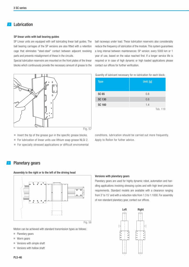
PLS-46
3 SC series
Planetary gears
Assembly to the right or to the left of the driving head
Motion can be achieved with standard transmission types as follows:
■ Planetary gears
■ Worm gears
■ Versions with simple shaft
■ Versions with hollow shaft
SP linear units with ball bearing guides
SP Linear units are equipped with self lubricating linear ball guides. The
ball bearing carriages of the SP versions are also fi tted with a retention
cage that eliminates "steel-steel" contact between adjacent revolving
parts and prevents misalignment of these in the circuits.
Special lubrication reservoirs are mounted on the front plates of the linear
blocks which continuously provide the necessary amount of grease to the
Tab. 119
Lubrication
■ Insert the tip of the grease gun in the specific grease blocks.
■ For lubrication of linear units use lithium soap grease NLGI 2.
■ For specially stressed applications or difficult enviromental
Type Unit: [g]
SC 65 0.8
SC 130 0.8
SC 160 1.4
Fig. 57
Quantity of lubricant necessary for re-lubrication for each block:
Fig. 58
Left Right
ball raceways under load. These lubrication reservoirs also considerably
reduce the frequency of lubrication of the module. This system guarantees
a long interval between maintenances: SP version: every 5000 km or 1
year of use, based on the value reached fi rst. If a longer service life is
required or in case of high dynamic or high loaded applications please
contact our offi ces for further verifi cation.
Versions with planetary gears
Planetary gears are used for highly dynamic robot, automation and han-
dling applications involving stressing cycles and with high level precision
requirements. Standard models are available with a clearance ranging
from 3' to 15' and with a reduction ratio from 1:3 to 1:1000. For assembly
of non-standard planetary gear, contact our offi ces.
conditions, lubrication should be carried out more frequently.
Apply to Rollon for futher advice.

PLS-47
Plus System
PLS
Simple shaft version
Simple shaft type AS
Position of the simple shaft can be to the left or right of the drive head.Fig. 59
Tab. 121
Unit Shaft type Head code
AS left
Head code
AS right
Head code
double AS
SC 65 AS 20 1EA 1CA 1AA
SC 130 AS 25 1EA 1CA 1AA
SC 160 AS 25 1EA 1CA 1AA
Unit Shaft type B D1
SC 65 AS 20 40 20h7
SC 130 AS 25 50 25h7
SC 160 AS 25 50 25h7
Tab. 120
B
D1 B
D1
Appliable
to unit
Shaft
type
D1 D2 D3 A B E F Keyway
B x H
Head
code
SC 65 SP AC 19 19H7 80 100 90 13 3 M6 6 x 6 2AA
SC 65 SP AC 20 20H7 80 100 90 13 3 M6 6 x 6 2BA
SC 130 SP AC 20 20H7 80 100 115 19 4.5 M6 6 x 6 2AA
SC 130 SP AC 25 25H7 110 130 115 19 4.5 M8 8 x 7 2BA
SC 160 SP AC 32 32H7 130 165 140 22 5.5 M10 10 x 8 2AA
Hollow shafts
AC hollow shaft type
Unit mm
An (optional) connection fl ange is required to fi t the standard reduction
units selected by Rollon.
For further information contact our offi ces
Fig. 60
Tab. 122
E D2
C
A
D
1
D3 4 x F

PLS-48
Accessories
Fixing by brackets
The ball bearing guide linear drive systems of Rollon SC series linear units
enable support of loads in any direction. They can therefore be installed in
any position. To install the SC series units, we recommend use of one of
the two systems indicated below:
Fixing brackets Material: Anodized aluminum
Direct fi xing
Unit A
(mm)
SC 65 SP 147
SC 130 SP 213
SC 160 SP 266
Unit A B C E F D1 D2 H1 L Code
SC 65 SP 20 6 16 10 5.5 9.5 5.3 14 35 1001491
SC 130 SP 20 7 16 12.7 7 10.5 6.5 18.7 50 1001491
SC 160 SP 36.5 10 31 18.5 10.5 16.5 10.5 28.5 100 1001233
Fig. 61
Fig. 62
Fig. 63
Tab. 123
Tab. 124
A
L D1
A
F
H1
E
C
B
D2
3 SC series

PLS-49
Plus System
PLS
T-nuts
Steel nuts to be used in the slots of the body
L = Side - I = Lower - C=Central
Proximity
Fitting of the proximity switch
Proximity switches can be mounted on four threaded mounting holes that
are positioned on the sides of the carriage. Do not over-torque the switch-
es during installation as this can cause interference with the proximity
switch runner and damage the sensor.
Sensor dog
L-shaped bracket in zinc-plated iron, mounted on the carriage and used
for proximity switch operations.
Unit Slot D3 D4 G H2 K Code
SC 65 L 6.7 M5 2.3 6.5 10 1000627
SC 130 L-I 8 M6 3.3 8.3 13 1000043
SC 130 C - M3 - 4 6 1001097
SC 160 I 8 M6 3.3 8.3 13 1000043
SC 160 L 11 M8 2.8 10.8 17 1000932
SC 160 C - M6 - 5.8 13 1000910
Tab. 125
Tab. 126
Fig. 66
Fig. 64
4 holes M12x1
Sensor dogProximityL4
B4
H4
Fixing by T-nuts
Warning:
Do not fi x the linear units through the drive ends.
Fig. 65
I ILL
CC
Unit B4 H4 L4 Sensor dog
Code
SC 65 8.5 23 50 G000270
SC 130 8.4 25 50 G000271
SC 160 10 27 50 G000272

PLS-50
3 SC series
Unit A B C D E
SC 65 135 109 54,5 100 340
SC 130 212 130 64 115 440
SC 160 248 150 73 120 525
Protections
Dimensions (mm)
Protection of ball bearing guides
The four ball bearing blocks have seals on both sides and, where neces-
sary, an additional scraper can be fi tted for very dusty conditions.
Special protection
For use in hostile conditions, the SC can be fi tted with bellows system in
addition to the standard protection. The bellows is fi xed to the carriage
and drive ends with hook and loop fasteners for ease of assembly and
disassembly.
The total length (L) of the linear unit will vary:
See Fig. 67.
Standard material: Thermally welded nylon coated with polyurethane
Materials on demand: Nylon coated with PVC, fi berglass, stainless steel
Warning: The use of bellows does not allow the assembly of the proximity
switch holders to the aluminum body.
Tab. 127
Fig. 67
D Pa E Pch D L = 2D + E + 2(Pch+5) + USEFUL STROKE
AP
A
B
C

PLS-51
Plus System
PLS
Identifi cation codes for the SC linear unit
Ordering key
S 13
06=65
13=130
16=160
1 CA 2000 1A
1A=SP
Linear motion system see pg. PLS-42
L = total length of the unit
Driving head code see pg. PLS-47
Linear unit size see from pg. PLS-43 to pg. PLS-45
Linear unit series SC see pg. PLS-40
In order to create identifi cation codes for Actuator Line, you can visit: http://confi gureactuator.rollon.com
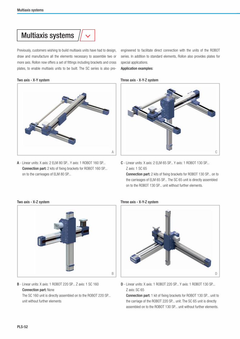
PLS-52
Two axis - X-Y system
Three axis - X-Y-Z system
Three axis - X-Y-Z system
Two axis - X-Z system
A
B D
A - Linear units: X axis: 2 ELM 80 SP... Y axis: 1 ROBOT 160 SP...
Connection part: 2 kits of fi xing brackets for ROBOT 160 SP...
on to the carrieages of ELM 80 SP...
C - Linear units: X axis: 2 ELM 65 SP... Y axis: 1 ROBOT 130 SP...
Z axis: 1 SC 65
Connection part: 2 kits of fi xing brackets for ROBOT 130 SP... on to
the carrieages of ELM 65 SP... The SC 65 unit is directly assembled
on to the ROBOT 130 SP... unit without further elements.
B - Linear units: X axis: 1 ROBOT 220 SP... Z axis: 1 SC 160
Connection part: None
The SC 160 unit is directly assembled on to the ROBOT 220 SP...
unit without further elements
D - Linear units: X axis: 1 ROBOT 220 SP... Y axis: 1 ROBOT 130 SP...
Z axis: SC 65
Connection part: 1 kit of fi xing brackets for ROBOT 130 SP... unit to
the carriage of the ROBOT 220 SP... unit. The SC 65 unit is directly
assembled on to the ROBOT 130 SP... unit without further elements.
Multiaxis systems
Multiaxis systems
Previously, customers wishing to build multiaxis units have had to design,
draw and manufacture all the elements necessary to assemble two or
more axis. Rollon now offers a set of fi ttings including brackets and cross
plates, to enable multiaxis units to be built. The SC series is also pre-
engineered to facilitate direct connection with the units of the ROBOT
series. In addition to standard elements, Rollon also provides plates for
special applications.
Application examples:
C

PLS-53
Plus System
PLS
Notes


Clean Room System
FrontespizioCleanRoomSystem.indd 1 22/11/2014 16:31:12
Linear units ONE series
INTL. PATENT PENDING

CRS-2
ONE series description
1 ONE series
Fig. 1
ONE series
The ONE series actuators are belt driven linear actuators specifi cally de-
signed for Clean Room applications. The ONE series is certifi ed compliant
with ISO CLASS 3 (DIN EN ISO 14644-1) and CLASS 1 US FED STD 209E
cleanroom standards by the Fraunhofer Institute IPA in Stuttgard.
The ONE series reduces particle contamination using a specially designed
straight seal that isolates the internals of the actuator from the environ-
ment. In addition to particle containment, the ONE series can support a
vacuum pump (up to 0,8 bar) to remove and transport contaminates from
the interior of the actuator to fi ltration sites. The 2 vacuum ports are lo-
cated on the drive and idle head.
All internal components of the ONE series actuators are designed to mini-
mize particle release. Component materials are limited to stainless steel.
Where stainless steel is not an option, special treatments are used to
ensure low particle release.
Special lubrications designed for use in cleanroom or vacuum environ-
ments are used for all bearings and linear rails.

CRS-3
Clean Room System
CRS
The components
General data about aluminum used: AL 6060
Chemical composition [%]
Physical characteristics
Mechanical characteristics
AI Mg Si Fe Mn Zn Cu Impurites
Remainder 0.35-0.60 0.30-0.60 0.30 0.10 0.10 0.10 0.05-0.15
Density Coeff. of
elasticity
Coeff. of thermal expansion
(20°-100°C)
Thermal conductivity
(20°C)
Specifi c heat
(0°-100°C)
Resistivity Melting point
kg___
dm3
kN___
mm2
10-6
___
K
W_____
m . K
J_____
kg . K
Ω . m . 10-9 °C
2.7 69 23 200 880-900 33 600-655
Rm Rp (02) A HB
N___
mm2
N___
mm2
% __
205 165 10 60-80
Extruded bodies
The anodized aluminium extrusions used for the bodies of the Rollon ONE
series linear units were designed and manufactured in cooperation with
a leading company in this field to obtain the right combination of high
mechanical strenght and reduced weight. Aluminium alloy 6060 is used
(see physical-chemical characteristics below).The dimensional tolerances
comply with EN 755-9 standard.
Driving belt
ONE Series is the fi rst linear units driven by timing belt capable to achieve
ISO CLASS 3.
We are using selected higth quality polyurethane timing belts, AT profi le,
manufactured by leading companies in this fi eld.
Tab. 1
Tab. 2
Tab. 3
Carriage
The carriage of the Rollon ONE series linear units are made entirely of
anodized aluminum. Each carriage has mounting holes fi tted with stain-
less steel thread inserts. Rollon offers multiple carriages to accommodate
a vast array of applications. The unique design of the carriage allows for
the sealing strip to pass through the carriage.
Sealing strip
Rollon ONE series linear units are equipped with a polyurethane sealing
strip to prevent particles generated inside the unit to go outside. The seal-
ing strip runs the length of the body and is kept in position by micro-bear-
ings located with in the carriage. This minimizes frictional resistance as
the strip passes through the carriage while providing maximum protection.

CRS-4
The linear motion system
Certifi ed Clean Room Class
ONE Series is a device tested by FRAUNHOFER IPA Institute - Stuttgart (D).
Rollon achieved the ISO CLASS 3 (DIN EN ISO 14644-1) and CLASS 1
US FED STD 209E cleanroom standard using a combination of a vacuum
pump and our special sealing belt (Intl. Patend Pending).
Vacuum system
The ONE series actuator has specifi c connection ports on the drive and
the idle end of the unit to connect a vacuum system. The vacuum quality
must be evaluated case by case, but Rollon has had success with 0,8 bar
on a ONE 80 with a stroke of 1.000 mm up to 4.000 mm. A vacuum was
used in conjunction to Rollon's special sealing strip to achieve ISO CLASS
3 (DIN EN ISO 14644-1) and CLASS 1 US FED STD 209E
Selected mechanical components
ONE Series is assembled with select high-quality components.
Only Stainless Steel (AISI 303, AISI 440C) is used for bearings, linear
guides, shafts, pulleys, and other metallic components. Where it is impos-
sible to use Stainless Steel, Rollon provides a special treatment tested
under severe conditions and under particle generation.
Lubrication
ONE Series is equiped with "innovate and hi-tech linear guides" that fea-
ture special ball cages to maintain spacing. This feature supports a long-
term maintenance and a low particle generation if combined with special
lubricant, specifi cally developed and adopted for Clean Room applications.
Range
ONE Series is now available in 3 different sizes, for multi axes combina-
tions:
■ ONE 50
■ ONE 80
■ ONE 100
Maximum stroke is 6.000 mm, except ONE 50 where the maximum stroke
is 3.700 mm.
For technical details and load capacities, please refer to next pages.
ONE SP section
Fig. 2
1 ONE series
Linear units ONE series
INTL. PATENT PENDING
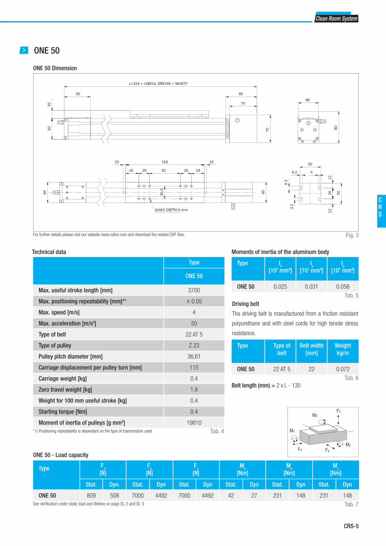
CRS-5
Clean Room System
CRS
ONE 50
ONE 50 Dimension
Fig. 3
70
70
80
2050
65
L=315 + USEFUL STROKE + SAFETY
10 10
6050
150
1826622618
30.5
8xM5 DEPTH 6 mm 4.2
8.3
50
1226
12
50
6.2 4
48
80
For further details please visit our website www.rollon.com and download the related DXF fi les.
Type
ONE 50
Max. useful stroke length [mm] 3700
Max. positioning repeatability [mm]*1 ± 0.05
Max. speed [m/s] 4
Max. acceleration [m/s2] 50
Type of belt 22 AT 5
Type of pulley Z 23
Pulley pitch diameter [mm] 36,61
Carriage displacement per pulley turn [mm] 115
Carriage weight [kg] 0.4
Zero travel weight [kg] 1.8
Weight for 100 mm useful stroke [kg] 0.4
Starting torque [Nm] 0.4
Moment of inertia of pulleys [g mm2] 19810
*1) Positioning repeatability is dependant on the type of transmission used
Technical data
Tab. 4
Type Fx
[N]
Fy
[N]
Fz
[N]
Mx
[Nm]
My
[Nm]
Mz
[Nm]
Stat. Dyn. Stat. Dyn Stat. Dyn Stat. Dyn Stat. Dyn Stat. Dyn
ONE 50 809 508 7000 4492 7000 4492 42 27 231 148 231 148
ONE 50 - Load capacity
See verifi cation under static load and lifetime on page SL-2 and SL-3 Tab. 7
Type Ix
[107 mm4]
Iy
[107 mm4]
Ip
[107 mm4]
ONE 50 0.025 0.031 0.056
Type Type of
belt
Belt width
[mm]
Weight
kg/m
ONE 50 22 AT 5 22 0.072
Moments of inertia of the aluminum body
Fx
MzFz
Mx
FyMy
Driving belt
The driving belt is manufactured from a friction resistant
polyurethane and with steel cords for high tensile stress
resistance.
Tab. 5
Tab. 6
Belt length (mm) = 2 x L - 130

CRS-6
ONE 80
ONE 80 Dimension
Fig. 4
105
105
120
3080
100
L=540 + USEFUL STROKE + SAFETY
10 10
8080
300
49421184249
48
8xM6 DEPTH 6 mm 8.4
13.5
80
1942
19
80
9.8 6
78
122.
5
For further details please visit our website www.rollon.com and download the related DXF fi les.
Type
ONE 80
Max. useful stroke length [mm] 6000
Max. positioning repeatability [mm]*1 ± 0.05
Max. speed [m/s] 5
Max. acceleration [m/s2] 50
Type of belt 32 AT 10
Type of pulley Z 19
Pulley pitch diameter [mm] 60.48
Carriage displacement per pulley turn [mm] 190
Carriage weight [kg] 2.7
Zero travel weight [kg] 10.5
Weight for 100 mm useful stroke [kg] 1
Starting torque [Nm] 2.2
Moment of inertia of pulleys [g mm2] 388075
*1) Positioning repeatability is dependant on the type of transmission used
Technical data
Tab. 8
Type Fx
[N]
Fy
[N]
Fz
[N]
Mx
[Nm]
My
[Nm]
Mz
[Nm]
Stat. Dyn. Stat. Dyn Stat. Dyn Stat. Dyn Stat. Dyn Stat. Dyn
ONE 80 2013 1170 38480 21735 46176 25875 398 223 3371 1889 2809 1587
ONE 80 - Load capacity
See verifi cation under static load and lifetime on page SL-2 and SL-3 Tab. 11
Type Ix
[107 mm4]
Iy
[107 mm4]
Ip
[107 mm4]
ONE 80 0.136 0.195 0.331
Type Type of
belt
Belt width
[mm]
Weight
kg/m
ONE 80 32 AT 10 32 0.185
Moments of inertia of the aluminum body
Fx
MzFz
Mx
FyMy
Driving belt
The driving belt is manufactured from a friction resistant
polyurethane and with steel cords for high tensile stress
resistance.
Tab. 9
Tab. 10
Belt length (mm) = 2 x L - 230
1 ONE series

CRS-7
Clean Room System
CRS
ONE 110
ONE 110 Dimension
Fig. 5
145
145
160
4011
0
135
L=695 + USEFUL STROKE + SAFETY
10 10
130
110
380
60601406060
70
8xM8 DEPTH 6 mm 11.3
18
110
2462
24
110
12 8.5
108
167.
5
For further details please visit our website www.rollon.com and download the related DXF fi les.
Type
ONE 110
Max. useful stroke length [mm] 6000
Max. positioning repeatability [mm]*1 ± 0.05
Max. speed [m/s] 5
Max. acceleration [m/s2] 50
Type of belt 50 AT 10
Type of pulley Z 27
Pulley pitch diameter [mm] 85.94
Carriage displacement per pulley turn [mm] 270
Carriage weight [kg] 5.6
Zero travel weight [kg] 22.5
Weight for 100 mm useful stroke [kg] 1.4
Starting torque [Nm] 3.5
Moment of inertia of pulleys [g mm2] 2.193 · 106
*1) Positioning repeatability is dependant on the type of transmission used
Technical data
Tab. 12
Type Fx
[N]
Fy
[N]
Fz
[N]
Mx
[Nm]
My
[Nm]
Mz
[Nm]
Stat. Dyn. Stat. Dyn Stat. Dyn Stat. Dyn Stat. Dyn Stat. Dyn
ONE 110 4440 2940 92300 46003 110760 54765 1110 549 9968 4929 8307 4140
ONE 110 - Load capacity
See verifi cation under static load and lifetime on page SL-2 and SL-3 Tab. 15
Type Ix
[107 mm4]
Iy
[107 mm4]
Ip
[107 mm4]
ONE 110 0.446 0.609 1.054
Type Type of
belt
Belt width
[mm]
Weight
kg/m
ONE 110 50 AT 10 50 0.290
Moments of inertia of the aluminum body
Fx
MzFz
Mx
FyMy
Driving belt
The driving belt is manufactured from a friction resistant
polyurethane and with steel cords for high tensile stress
resistance.
Tab. 13
Tab. 14
Belt length (mm) = 2 x L - 290

CRS-8
Right
Left
Unit Shaft type D2 D3 M Head code
AS left
Head code
AS right
ONE 50 AS 12 55 70 M5 VB VA
ONE 80 AS 20 80 100 M6 VB VA
ONE 110 AS 25 110 130/160 M8 VB VA
Shaft with centering
Fig. 7
Tab. 16
1 ONE series
D3
D
2
4 x M
Planetary gears
Assembly to the right or to the left of the driving head
The series ONE linear units can be fi tted with several different drive
systems. In each case, the driving pulley is attached to the reduction
gearshaft by means of a tapered coupling to ensure high accuracy over a
long period of time.
Fig. 6
Versions with planetary gears
Planetary gears are used for highly dynamic robot, automation and
handling applications involving stressing cycles and with high level
precision requirements. Standard models are available with clearance
from 3' to 15' and with a reduction ratio from 1:3 to 1:1000. For assembly
of non-standard planetary gear, contact our offi ces.

CRS-9
Clean Room System
CRS
Accessories
Fixing by brackets
The linear motion systems used for the Rollon series ONE linear units
enables them to support loads in any direction. They can therefore be
installed in any position.
To install the units, we recommend the use of the dedicated T-Slots in the
extruded bodies as shown below.
Warning:
Do not fi x the linear units through the drive ends.
Fixing brackets
T-Nuts
Fig. 8
Fig. 9
Fig. 10
Unit A
(mm)
ONE 50 62
ONE 80 94
ONE 110 130
Tab. 17
Fixing bracket
Anodized aluminum block for fi xing the linear units through the side T-Slots of the body.
T-nuts
Steel nuts to be used in the slots of the body.
Unit A H1 B C E F D1 D2 L L1 Code
ONE 50 20 14 6 16 10 6 10 5.5 35 17.5 1000958
ONE 80 20 20.7 7 16 14.7 7 11 6.4 50 25 1001491
ONE 110 36.5 28.5 10 31 18.5 11.5 16.5 10.5 100 50 1001233
Unit D3 D4 G H2 K Code
ONE 50 - M4 - 3.4 8 1001046
ONE 80 8 M6 3.3 8.3 13 1000043
ONE 110 11 M8 2.8 10.8 17 1000932
Dimensions (mm)
Dimensions (mm)
Tab. 18
Tab. 19
LØ D1
Ø D4
Ø D3
Ø D2
H1
H2
G
E
F
A
CB
L1
K
A

CRS-10
Proximity
Dimensions (mm)
Sensor proximity housing kit
Red anodized aluminum sensor holder, equipped with T-nuts for fi xing
onto the profi le.
Sensor dog
L-shaped bracket in zinc-plated iron, mounted on the carriage and used
for proximity switch operations.
Tab. 20
Fig. 11
Unit B4 B5 L4 L5 H4 H5 For
proximity
Sensor dog
code
Sensor proximity
housing kit code
ONE 50 9.5 14 25 29 11.9 22.5 Ø 8 G000268 G000211
ONE 80 17.2 20 50 40 17 32 Ø 12 G000267 G000209
ONE 110 17.2 20 50 40 17 32 Ø 12 G000267 G000210
L4 L5
Sensor dog
Sensor proximityhousing kit
B5
H5
H
4
B4
Sensor proximityhousing kit
Sensor dog
1 ONE series

CRS-11
Clean Room System
CRS
Ordering key
Identifi cation codes for the ONE linear unit
N 08
05=50
08=80
10=100
VA O2000 3B
SP stainless steel see pg. CRS-3
L= total length of the unit
Driving head code see pg. CRS-8
Linear unit size see from pg. CRS-5 to pg. CRS-7
ONE Series see pg. CRS-2
In order to create identifi cation codes for Actuator Line, you can visit: http://confi gureactuator.rollon.com


Smart System
FrontespizioSmartSystem.indd 1 22/11/2014 16:30:42

SS-2
1 E-SMART series
E-SMART
The E-SMART series linear units have an extruded and anodized aluminum
self-supporting structure with a profi le available in four sizes from 30 to
100mm. Transmission is achieved with a polyurethane steel reinforced
driving belt. Also featured is a single rail with one or more recirculating
ball bearing runner blocks.
E-SMART series description
Fig. 1
E-SMART series

SS-3
Smart System
SS
General data about aluminum used: AL 6060
Chemical composition [%]
Physical characteristics
Mechanical characteristics
AI Mg Si Fe Mn Zn Cu Impurites
Remainder 0.35-0.60 0.30-0.60 0.30 0.10 0.10 0.10 0.05-0.15
Density Coeff. of
elasticity
Coeff. of thermal expansion
(20°-100°C)
Thermal conductivity
(20°C)
Specifi c heat
(0°-100°C)
Resistivity Melting point
kg___
dm3
kN___
mm2
10-6
___
K
W_____
m . K
J_____
kg . K
Ω . m . 10-9 °C
2.7 70 23.8 200 880-900 33 600-655
Rm Rp (02) A HB
N___
mm2
N___
mm2
% __
250 200 10 75
Tab. 1
Tab. 2
Tab. 3
The components
Extruded bodies
The anodized aluminum extrusions used for the bodies of the Rollon
SMART series linear units were designed and manufactured in coopera-
tion with a leading company in this fi eld to obtain the right combination
of high mechanical strength and reduced weight. The anodized aluminum
alloy 6060 used (see physical chemical characteristics below for further
information) was extruded with dimensional tolerances complying with EN
755-9 standards.
Driving belt
The Rollon SMART series linear units use steel reinforced polyurethane
drive belts with AT pitch. This type of belt is ideal due to its high load trans-
mission characteristics, compact size, and low noise. Used in conjunction
with a backlash-free pulley, smooth alternating motion can be achieved.
Optimization of the maximum belt width/body dimension ratio enables the
following performance characteristics to be achieved:
■ High speed
■ Low noise
■ Low wear
Carriage
The carriage of the Rollon SMART series linear units is made entirely of
machined anodized aluminum. The dimensions vary depending on the type.
Rollon offers multiple carriages to accomodate a vast array of applications.

SS-4
1 E-SMART series
The linear motion system
The linear motion system has been designed to meet the load capacity,
speed, and maximum acceleration conditions of a wide variety of applica-
tions.
Performance characteristics:
■ The ball bearing guides with high load capacity are mounted in a dedi-
cated seat on the aluminum body.
■ The carriage of the linear unit is assembled on preloaded ball bearing
blocks that enables the carriage to withstand loading in the four main
directions.
■ The ball bearing carriages of the SP versions are also fi tted with a
retention cage that eliminates "steel-steel" contact between adjacent
revolving parts and prevents misalignment.
■ The blocks have seals on both sides and, when necessary, an addi-
tional scraper can be fi tted for very dusty conditions.
Fig. 2
E-SMART section
The linear motion system described above offers:
■ High speed and acceleration
■ High load capacity
■ High permissible bending moments
■ Low friction
■ Long life
■ Low noise
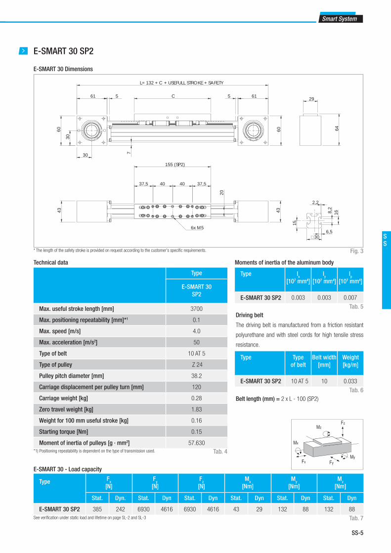
SS-5
Smart System
SS
E-SMART 30 SP2
* The length of the safety stroke is provided on request according to the customer's specifi c requirements.
E-SMART 30 Dimensions
Type
E-SMART 30
SP2
Max. useful stroke length [mm] 3700
Max. positioning repeatability [mm]*1 0.1
Max. speed [m/s] 4.0
Max. acceleration [m/s2] 50
Type of belt 10 AT 5
Type of pulley Z 24
Pulley pitch diameter [mm] 38.2
Carriage displacement per pulley turn [mm] 120
Carriage weight [kg] 0.28
Zero travel weight [kg] 1.83
Weight for 100 mm useful stroke [kg] 0.16
Starting torque [Nm] 0.15
Moment of inertia of pulleys [g · mm2] 57.630
*1) Positioning repeatability is dependent on the type of transmission used.
Technical data
Tab. 4
Type Fx
[N]
Fy
[N]
Fz
[N]
Mx
[Nm]
My
[Nm]
Mz
[Nm]
Stat. Dyn. Stat. Dyn Stat. Dyn Stat. Dyn Stat. Dyn Stat. Dyn
E-SMART 30 SP2 385 242 6930 4616 6930 4616 43 29 132 88 132 88
E-SMART 30 - Load capacity
See verifi cation under static load and lifetime on page SL-2 and SL-3 Tab. 7
Type Ix
[107 mm4]
Iy
[107 mm4]
Ip
[107 mm4]
E-SMART 30 SP2 0.003 0.003 0.007
Type Type
of belt
Belt width
[mm]
Weight
[kg/m]
E-SMART 30 SP2 10 AT 5 10 0.033
Moments of inertia of the aluminum body
Driving belt
The driving belt is manufactured from a friction resistant
polyurethane and with steel cords for high tensile stress
resistance.
Tab. 5
Tab. 6
Fig. 3
Fx
MzFz
Mx
FyMy
Belt length (mm) = 2 x L - 100 (SP2)
7
61
60
30
60
61
30
L= 132 + C + USEFULL STROKE + SAFETY
C 5 5 29
64
43
155 (SP2)
20
40 40 37,5 37,5
6x M5
43
30
2,2
6,5
16
8
,2
15

SS-6
1 E-SMART series
E-SMART 50 SP1 - SP2 - SP3
* The length of the safety stroke is provided on request according to the customer's specifi c requirements.
E-SMART 50 Dimensions
Type
E-SMART
50 SP1
E-SMART
50 SP2
E-SMART
50 SP3
Max. useful stroke length [mm]*16120 6050 5950
Max. positioning repeatability [mm]*20.1 0.1 0.1
Max. speed [m/s] 4.0 4.0 4.0
Max. acceleration [m/s2] 50 50 50
Type of belt 25 AT 5 25 AT 5 25 AT 5
Type of pulley Z 40 Z 40 Z 40
Pulley pitch diameter [mm] 63.66 63.66 63.66
Carriage displacement per pulley turn [mm] 200 200 200
Carriage weight [kg] 0.54 0.85 1.21
Zero travel weight [kg] 4.89 5.4 6.16
Weight for 100 mm useful stroke [kg] 0.34 0.34 0.34
Starting torque [Nm] 0.35 0.345 0.55
Moment of inertia of pulleys [g · mm2] 891.270 891.270 891.270
*1) It is possible to obtain stroke up to 11.270 (SP1), 11.200 (SP2), 11.100 (SP3) by means of special Rollon joints.
*2) Positioning repeatability is dependent on the type of transmission used.
Technical data
Tab. 8
Type Fx
[N]
Fy
[N]
Fz
[N]
Mx
[Nm]
My
[Nm]
Mz
[Nm]
Stat. Dyn. Stat. Dyn Stat. Dyn Stat. Dyn Stat. Dyn Stat. Dyn
E-SMART 50 SP1 1050 750 15280 9945 15280 9945 120 78 90 59 90 59
E-SMART 50 SP2 1050 750 30560 19890 30560 19890 240 156 856 557 856 557
E-SMART 50 SP3 1050 750 45840 29835 45840 29835 360 234 2582 1681 2582 1681
E-SMART 50 - Load capacity
See verifi cation under static load and lifetime on page SL-2 and SL-3 Tab. 11
Type Ix
[107 mm4]
Iy
[107 mm4]
Ip
[107 mm4]
E-SMART 50 SP 0.021 0.020 0.041
Type Type
of belt
Belt width
[mm]
Weight
[kg/m]
E-SMART 50 SP 25 AT 5 25 0.080
Moments of inertia of the aluminum body
Driving belt
The driving belt is manufactured from a friction resistant
polyurethane and with steel cords for high tensile stress
resistance.
Tab. 9
Tab. 10
Fig. 4
Fx
MzFz
Mx
FyMy
C 89
85.
5
42.
1
99 41.5
89
L = 189 + C + USEFUL STROKE + SAFETY
5.5 5.5
70
70
230 (SP2)
30
49 66 66 49
6 x M5
48
88
160 (SP1)
48
30
47.5 65 47.5
4 x M5
48
30
49 75 82 75 49
330 (SP3) 8 x M5
50
25
11.5
8.2
21
3
Belt length (mm) = 2 x L - 60 (SP1)
2 x L - 125 (SP2)
2 x L - 225 (SP3)

SS-7
Smart System
SS
Belt length (mm) = 2 x L - 135 (SP1)
2 x L - 225 (SP2)
E-SMART 80 SP1 - SP2
* The length of the safety stroke is provided on request according to the customer's specifi c requirements.
E-SMART 80 Dimensions
Type
E-SMART
80 SP1
E-SMART
80 SP2
Max. useful stroke length [mm]*1 6060 5970
Max. positioning repeatability [mm]*2 0.1 0.1
Max. speed [m/s] 4.0 4.0
Max. acceleration [m/s2] 50 50
Type of belt 32 AT 10 32 AT 10
Type of pulley Z 21 Z 21
Pulley pitch diameter [mm] 66,84 66,84
Carriage displacement per pulley turn [mm] 210 210
Carriage weight [kg] 1.34 1.97
Zero travel weight [kg] 9.94 11.31
Weight for 100 mm useful stroke [kg] 0.76 0.76
Starting torque [Nm] 0.95 1.3
Moment of inertia of pulleys [g · mm2] 938.860 938.860
*1) It is possible to obtain stroke up to 11.190 (SP1), 11.100 (SP2) by means of special Rollon joints.
*2) Positioning repeatability is dependent on the type of transmission used.
Technical data
Tab. 12
Type Fx
[N]
Fy
[N]
Fz
[N]
Mx
[Nm]
My
[Nm]
Mz
[Nm]
Stat. Dyn. Stat. Dyn Stat. Dyn Stat. Dyn Stat. Dyn Stat. Dyn
E-SMART 80 SP1 2250 1459 25630 18318 25630 18318 260 186 190 136 190 136
E-SMART 80 SP2 2250 1459 51260 36637 51260 36637 520 372 1874 1339 1874 1339
E-SMART 80 - Load capacity
See verifi cation under static load and lifetime on page SL-2 and SL-3 Tab. 15
Type Ix
[107 mm4]
Iy
[107 mm4]
Ip
[107 mm4]
E-SMART 80 SP 0.143 0.137 0.280
Type Type
of belt
Belt width
[mm]
Weight
[kg/m]
E-SMART 80 SP 32 AT 10 32 0.186
Moments of inertia of the aluminum body
Driving belt
The driving belt is manufactured from a friction resistant
polyurethane and with steel cords for high tensile stress
resistance.
Tab. 13
Tab. 14
Fig. 5
Fx
MzFz
Mx
FyMy
77
118 10 C 11810
118.
6
57.5
115
118.
6
L= 256 + C + USELFUL STROKE + SAFETY
65 85 85 65300 (SP2)
50 80.4
80.4
6x M6
124
78
2040
20
20 40 20
80
8.2
311.5
20
65 80 65
78
210 (SP1) 5
0 4x M6

SS-8
Belt length (mm) = 2 x L - 325 (SP3)
2 x L - 405 (SP4)
E-SMART 80 SP3 - SP4
* The length of the safety stroke is provided on request according to the customer's specifi c requirements.
E-SMART 80 Dimensions
Type
E-SMART
80 SP3
E-SMART
80 SP4
Max. useful stroke length [mm]*1 5870 5790
Max. positioning repeatability [mm]*2 0.1 0.1
Max. speed [m/s] 4.0 4.0
Max. acceleration [m/s2] 50 50
Type of belt 32 AT 10 32 AT 10
Type of pulley Z 21 Z 21
Pulley pitch diameter [mm] 66,84 66,84
Carriage displacement per pulley turn [mm] 210 210
Carriage weight [kg] 2.63 3.23
Zero travel weight [kg] 12.83 14.06
Weight for 100 mm useful stroke [kg] 0.76 0.76
Starting torque [Nm] 1.4 1.52
Moment of inertia of pulleys [g · mm2] 938.860 938.860
*1) It is possible to obtain stroke up to 11.000 (SP3), 10.920 (SP4) by means of special Rollon joints.
*2) Positioning repeatability is dependent on the type of transmission used.
Technical data
Tab. 16
Type Fx
[N]
Fy
[N]
Fz
[N]
Mx
[Nm]
My
[Nm]
Mz
[Nm]
Stat. Dyn. Stat. Dyn Stat. Dyn Stat. Dyn Stat. Dyn Stat. Dyn
E-SMART 80 SP3 2250 1459 76890 54956 76890 54956 780 557 4870 3481 4870 3481
E-SMART 80 SP4 2250 1459 102520 73274 102520 73274 1040 743 7689 5496 7689 5496
E-SMART 80 - Load capacity
See verifi cation under static load and lifetime on page SL-2 and SL-3 Tab. 19
Type Ix
[107 mm4]
Iy
[107 mm4]
Ip
[107 mm4]
E-SMART 80 SP 0.143 0.137 0.280
Type Type
of belt
Belt width
[mm]
Weight
[kg/m]
E-SMART 80 SP 32 AT 10 32 0.186
Moments of inertia of the aluminum body
Driving belt
The driving belt is manufactured from a friction resistant
polyurethane and with steel cords for high tensile stress
resistance.
Tab. 17
Tab. 18
Fig. 6
Fx
MzFz
Mx
FyMy
77
118 10 C 11810
118.
6
57.5
115
118.
6
L= 256 + C + USELFUL STROKE + SAFETY
124
78
400 (SP3)
78
50
65 140 65 65 65
8 x M6 480 (SP4)
78
50
65 70 70 70 70 70 65
12 x M6
1 E-SMART series

SS-9
Smart System
SS
Belt length (mm) = 2 x L - 120 (SP1)
2 x L - 275 (SP2)
E-SMART 100 SP1 - SP2
* The length of the safety stroke is provided on request according to the customer's specifi c requirements.
E-SMART 100 Dimensions
Type
E-SMART
100 SP1
E-SMART
100 SP2
Max. useful stroke length [mm]*1 6025 5870
Max. positioning repeatability [mm]*2 0.1 0.1
Max. speed [m/s] 4.0 4.0
Max. acceleration [m/s2] 50 50
Type of belt 50 AT 10 50 AT 10
Type of pulley Z 27 Z 27
Pulley pitch diameter [mm] 85.94 85.94
Carriage displacement per pulley turn [mm] 270 270
Carriage weight [kg] 2.72 4.42
Zero travel weight [kg] 18.86 22.38
Weight for 100 mm useful stroke [kg] 1.3 1.3
Starting torque [Nm] 2.1 2.4
Moment of inertia of pulleys [g · mm2] 4.035.390 4.035.390
Technical data
Tab. 20
Type Fx
[N]
Fy
[N]
Fz
[N]
Mx
[Nm]
My
[Nm]
Mz
[Nm]
Stat. Dyn. Stat. Dyn Stat. Dyn Stat. Dyn Stat. Dyn Stat. Dyn
E-SMART 100 SP1 4440 3060 43620 31192 43620 31192 500 358 450 322 450 322
E-SMART 100 SP2 4440 3060 87240 62385 87240 62385 1000 715 5527 3952 5527 3952
E-SMART 100 Load capacity
See verifi cation under static load and lifetime on page SL-2 and SL-3 Tab. 23
Type Ix
[107 mm4]
Iy
[107 mm4]
Ip
[107 mm4]
E-SMART 100 SP 0.247 0.316 0.536
Type Type
of belt
Belt width
[mm]
Weight
[kg/m]
E-SMART 100 SP 50 AT 10 50 0.290
Moments of inertia of the aluminum body
Driving belt
The driving belt is manufactured from a friction resistant
polyurethane and with steel cords for high tensile stress
resistance.
Tab. 21
Tab. 22
Fig. 7
Fx
MzFz
Mx
FyMy
98
149
63.5
134
137 10 C 13710
L = 294 + C + USEFUL STROKE + SAFETY
146.
5
146.
5
8311
0.4
400 (SP2)70 60 140 60 70
70
8 x M8
110.
47098
45.560
6045.5
8 x M8
245 (SP1) 8.3 11.8
20
8
.35
25 50 25 100
25
4
0
25
*1) It is possible to obtain stroke up to 11.155 (SP1), 11.000 (SP2) by means of special Rollon joints.
*2) Positioning repeatability is dependent on the type of transmission used.

SS-10
1 E-SMART series
Belt length (mm) = 2 x L - 395 (SP3)
2 x L - 252 (SP4)
E-SMART 100 SP3 - SP4
* The length of the safety stroke is provided on request according to the customer's specifi c requirements.
E-SMART 100 Dimensions
Type
E-SMART
100 SP3
E-SMART
100 SP4
Max. useful stroke length [mm]*1 5790 5620
Max. positioning repeatability [mm]*2 0.1 0.1
Max. speed [m/s] 4.0 4.0
Max. acceleration [m/s2] 50 50
Type of belt 50 AT 10 50 AT 10
Type of pulley Z 27 Z 27
Pulley pitch diameter [mm] 85.94 85.94
Carriage displacement per pulley turn [mm] 270 270
Carriage weight [kg] 5.85 7.34
Zero travel weight [kg] 25.22 28.25
Weight for 100 mm useful stroke [kg] 1.3 1.3
Starting torque [Nm] 2.6 2.8
Moment of inertia of pulleys [g · mm2] 4.035.390 4.035.390
Technical data
Tab. 24
Type Fx
[N]
Fy
[N]
Fz
[N]
Mx
[Nm]
My
[Nm]
Mz
[Nm]
Stat. Dyn. Stat. Dyn Stat. Dyn Stat. Dyn Stat. Dyn Stat. Dyn
E-SMART 100 SP3 4440 3060 130860 93577 130860 93577 1500 1073 12039 8609 12039 8609
E-SMART 100 SP4 4440 3060 174480 124770 174480 124770 200 1430 19416 13884 19416 13884
E-SMART 100 Load capacity
See verifi cation under static load and lifetime on page SL-2 and SL-3 Tab. 27
Type Ix
[107 mm4]
Iy
[107 mm4]
Ip
[107 mm4]
E-SMART 100 SP 0.247 0.316 0.536
Type Type
of belt
Belt width
[mm]
Weight
[kg/m]
E-SMART 100 SP 50 AT 10 50 0.290
Moments of inertia of the aluminum body
Driving belt
The driving belt is manufactured from a friction resistant
polyurethane and with steel cords for high tensile stress
resistance.
Tab. 25
Tab. 26
Fig. 8
Fx
MzFz
Mx
FyMy
*1) It is possible to obtain stroke up to 10.880 (SP3), 10.750 (SP4) by means of special Rollon joints.
*2) Positioning repeatability is dependent on the type of transmission used.
137 10
C
146
.5
83
63.5 134
137 10
146
.5
L = 294 + C + USEFUL STROKE + SAFETY 1
10.4
400 (SP4)
70 60 140 60 70
8 x M8
70
98
149
98
520 (SP3)
70
60 60 140 60 60 70 70
12 x M8 650 (SP4)
98
70
75 60 60 60 140 60 60 60 75
16 x M8

SS-11
Smart System
SS
Lubrication
SP linear units with ball bearing guides
The ball bearing carriages of the SP versions are fi tted with a retention
cage that eliminates "steel-steel" contact between adjacent revolving
parts and prevents misalignment of these in the circuits.
This system guarantees a long interval between maintenances: SP ver-
sion: every 5000 km or 1 year of use, based on the value reached fi rst. If
■ Insert the tip of the grease gun into the specifi c grease blocks.
■ Type of lubricant: Lithium soap grease of class NLGI 2.
■ For specially stressed applications or hostile environmental conditions,
lubrication should be applied out more frequently.
Contact Rollon for further advice
Tab. 28
E-SMART
Type Unit [g]
E-SMART 30 1
E-SMART 50 1
E-SMART 80 2-3
E-SMART 100 5-6
a longer service life is required or in case of high dynamic or high loaded
applications please contact our offi ces for further verifi cation.
Fig. 9
Quantity of lubricant necessary for re-lubrication for each block:
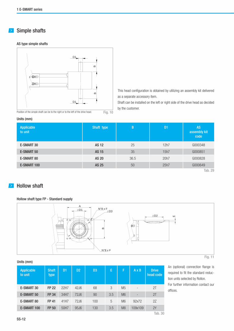
SS-12
Applicable
to unit
Shaft type B D1 AS
assembly kit
code
E-SMART 30 AS 12 25 12h7 G000348
E-SMART 50 AS 15 35 15h7 G000851
E-SMART 80 AS 20 36.5 20h7 G000828
E-SMART 100 AS 25 50 25h7 G000649
Simple shafts
AS type simple shafts
Units (mm)
Position of the simple shaft can be to the right or to the left of the drive head. Fig. 10
Tab. 29
B
D1
B
D1
1 E-SMART series
Hollow shaft
Hollow shaft type FP - Standard supply
Units (mm)
Fig. 11
Tab. 30
An (optional) connection fl ange is
required to fi t the standard reduc-
tion units selected by Rollon.
For further information contact our
offi ces.
This head confi guration is obtained by utilizing an assembly kit delivered
as a separate accessory item.
Shaft can be installed on the left or right side of the drive head as decided
by the customer.
Applicable
to unit
Shaft
type
D1 D2 D3 E F A x B Drive
head code
E-SMART 30 FP 22 22H7 42J6 68 3 M5 - 2T
E-SMART 50 FP 34 34H7 72J6 90 3.5 M6 - 2T
E-SMART 80 FP 41 41H7 72J6 100 5 M6 92x72 2Z
E-SMART 100 FP 50 50H7 95J6 130 3.5 M8 109x109 2Y
D2
E
D3
A
B
N°8 x F
N°8 x F
D1

SS-13
Smart System
SS
Linear units in parallel
Synchronization kit for use of SMART linear units in parallel
When movement consisting of two linear units in parallel is essential, a
synchronization kit must be used. This consists of original Rollon lamina
type precision joints complete with tapered splines and hollow aluminum
drive shafts.
Fig. 12
Applicable
to unit
Shaft type D7 D8 D9 Code Formula for length
calculation
E-SMART 30 AP 12 12 25 45 GK12P...1A L= X-51 [mm]
E-SMART 50 AP 15 15 40 69.5 GK15P...1A L= X-79 [mm]
E-SMART 80 AP 20 20 40 69.5 GK20P...1A L= X-97 [mm]
E-SMART 100 AP 25 25 70 99 GK25P...1A L= X-145 [mm]
Dimensions (mm)
Fig. 13
Tab. 31
D
8 L
D
9
D
7
X
Accessories
Fixing by brackets
The ball bearing guide linear drive system of Rollon SMART System series
linear units enables them to support loads in any direction.
They can therefore be installed in any position.
To install the SMART System series units, we recommend use of one of
the systems indicated below:
A B
E-SMART 30 42 -
E-SMART 50 62 -
E-SMART 80 92 40
E-SMART 100 120 50
Fig. 14
Dimensions (mm)
Tab. 32
A B

SS-14
T-nuts
C H L D Cod. Rollon
E-SMART 30 16 17.5 50 M5 1001490
E-SMART 50 16 26.9 50 M5 1000097
E-SMART 80 16 20.7 50 M5 1000111
E-SMART 100 31 28.5 100 M10 1002377
Hole Length Cod. Rollon
E-SMART 30 M5 20 6000436
E-SMART 50 M6 20 6000437
E-SMART 80 M6 20 6000437
E-SMART 100 M6 20 6000437
Dimensions (mm) Units (mm)
Fig. 15 Fig. 16
Tab. 33 Tab. 34
Proximity
Units (mm)
Fig. 17
Tab. 35
B4 B5 L4 L5 H4 H5 For proximity Sensor dog
code
Sensor
proximity
kit code
E-SMART 30 30 30 30 30 15 30 Ø 8 G000847 G000901
E-SMART 50 26 30 15 30 32 30 Ø 8 G000833 G000838
E-SMART 80 26 30 15 30 32 30 Ø 8 G000833 G000838
E-SMART 100 26 30 15 30 32 30 Ø 8 G000833 G000838
Sensor dog
Sensor proximity housing kit
B4
B5
H5H4
L5
L4
Sensor proximity housing kit
Aluminum block equipped with T-nuts for fi xing
Sensor dog
Iron plate mounted on the carriage used for the proximity operation
1 E-SMART series
L L/2
H
C
D
Fixing brackets
Steel nuts to be used in the slots of the body.

SS-15
Smart System
SS
Unit
type
Gearbox type
(not included)
Kit Code
E-SMART 30
MP053 G000356
LCO50; LPO50; PE2 G000357
SW030 G000383
E-SMART 50
MP060; PLE60 G000852
LCO70; MPV00; LPO70; PE3 G000853
SW040 G000854
E-SMART 80
P3 G000824
MP080 G000826
LCO90; MPV01; LPO90; PE4 G000827
MP105 G000830
PE3; LP070 G001078
SPO75; PLN090 G000859
SP060; PLN070 G000829
SW040 G000866
SW050 G000895
E-SMART 100
MP130 G000482
LC120; MPV02; LP120; PE5 G000483
LC090 G000525
MP105 G000527
SW050 G000717
Tab. 36
Fig. 18 Fig. 19
Adapter fl ange for gearbox assembly
Assembly kit includes: shrink disk; adapter plate; fi xing hardware
For other gearbox type ask Rollon

SS-16
Identifi cation codes for the E-SMART linear unit
Ordering key
L 10
03 = 30
05 = 50
08 = 80
10 = 100
2Y 02000 2A
Type (30) 2S=SP2
Type (50-80) 1T=SP1 - 2T=SP2 - 3T=SP3 - 4T=SP4
Type (100) 1A=SP1 - 2A=SP2 - 3A=SP3 - 4A=SP4
L=total length of the unit
Drive head code see pg. SS-12
Linear unit type see from pg. SS-5 to pg. SS-10
Linear unit series E-SMART see pg. SS-2
Ordering key
In order to create identifi cation codes for Actuator Line, you can visit: http://confi gureactuator.rollon.com

SS-17
Smart System
SS
R-SMART
The R-SMART series linear units are particularly suitable for: heavy loads,
pulling and pushing very heavy weights, demanding work cycles, possible
cantilever or gantry mounting, and operation in industrial automated lines.
The extruded and anodized aluminum self-supporting structure with a
rectangular section is available in three sizes ranging from 120 to 220
mm. Transmission is achieved with a polyurethane steel reinforced driving
belt. Also featured is a dual rail system with four or more recirculating ball
bearing runner blocks. Multiple sliders are available to further improve
load capacity.
These units are best used in applications requiring very heavy loads in
extremely confi ned spaces, and where machines cannot be stopped to
carry out ordinary system maintenance.
R-SMART series description
Fig. 20
R-SMART series
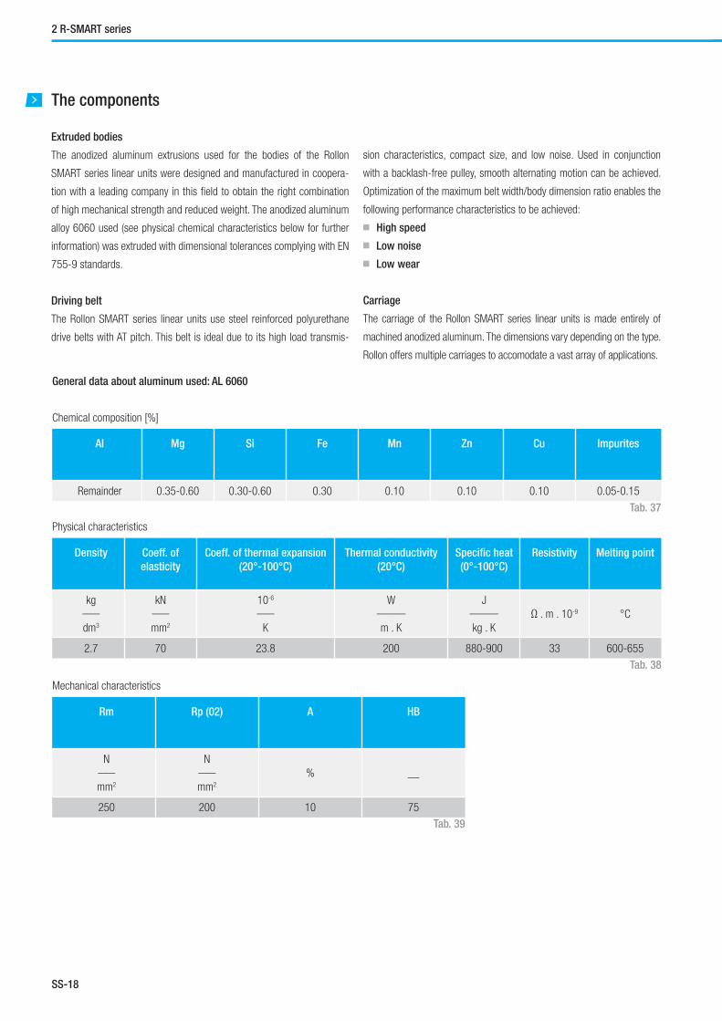
SS-18
The components
General data about aluminum used: AL 6060
Chemical composition [%]
Physical characteristics
Mechanical characteristics
AI Mg Si Fe Mn Zn Cu Impurites
Remainder 0.35-0.60 0.30-0.60 0.30 0.10 0.10 0.10 0.05-0.15
Density Coeff. of
elasticity
Coeff. of thermal expansion
(20°-100°C)
Thermal conductivity
(20°C)
Specifi c heat
(0°-100°C)
Resistivity Melting point
kg___
dm3
kN___
mm2
10-6
___
K
W_____
m . K
J_____
kg . K
Ω . m . 10-9 °C
2.7 70 23.8 200 880-900 33 600-655
Rm Rp (02) A HB
N___
mm2
N___
mm2
% __
250 200 10 75
Tab. 37
Tab. 38
Tab. 39
Extruded bodies
The anodized aluminum extrusions used for the bodies of the Rollon
SMART series linear units were designed and manufactured in coopera-
tion with a leading company in this fi eld to obtain the right combination
of high mechanical strength and reduced weight. The anodized aluminum
alloy 6060 used (see physical chemical characteristics below for further
information) was extruded with dimensional tolerances complying with EN
755-9 standards.
Driving belt
The Rollon SMART series linear units use steel reinforced polyurethane
drive belts with AT pitch. This belt is ideal due to its high load transmis-
2 R-SMART series
sion characteristics, compact size, and low noise. Used in conjunction
with a backlash-free pulley, smooth alternating motion can be achieved.
Optimization of the maximum belt width/body dimension ratio enables the
following performance characteristics to be achieved:
■ High speed
■ Low noise
■ Low wear
Carriage
The carriage of the Rollon SMART series linear units is made entirely of
machined anodized aluminum. The dimensions vary depending on the type.
Rollon offers multiple carriages to accomodate a vast array of applications.

SS-19
Smart System
SS
The linear motion system
The linear motion system has been designed to meet the load capacity,
speed, and maximum acceleration conditions of a wide variety of applica-
tions. Rollon SMART series systems feature a linear motion system with
ball bearing guides:
Performance characteristics:
■ The ball bearing guides with high load capacity are mounted in a dedi-
cated seat on the aluminum body.
■ The carriage of the linear unit is assembled on preloaded ball bearing
blocks that enables the carriage to withstand loading in the four main
directions.
■ The ball bearing carriages of the SP versions are also fi tted with a
retention cage that eliminates "steel-steel" contact between adjacent
revolving parts and prevents misalignment.
■ The blocks have seals on both sides and, when necessary, an addi-
tional scraper can be fi tted for very dusty conditions.
R-SMART section
Fig. 21
The linear motion system described above offers:
■ High speed and acceleration
■ High load capacity
■ High permissible bending moments
■ Low friction
■ Long life
■ Low noise

SS-20
R-SMART 120 SP4 - SP6
* The length of the safety stroke is provided on request according to the customer's specifi c requirements.
R-SMART 120 Dimensions
Type
R-SMART
120 SP4
R-SMART
120 SP6
Max. useful stroke length [mm]*1 6050 5930
Max. positioning repeatability [mm]*2 0.1 0.1
Max. speed [m/s] 4.0 4.0
Max. acceleration [m/s2] 50 50
Type of belt 40 AT 10 40 AT 10
Type of pulley Z 21 Z 21
Pulley pitch diameter [mm] 66.84 66.84
Carriage displacement per pulley turn [mm] 210 210
Carriage weight [kg] 3 4
Zero travel weight [kg] 12.9 15
Weight for 100 mm useful stroke [kg] 0.9 0.9
Starting torque [Nm] 1.95 2.3
Moment of inertia of pulleys [g · mm2] 1.054.300 1.054.300
Technical data
Tab. 40
Type Fx
[N]
Fy
[N]
Fz
[N]
Mx
[Nm]
My
[Nm]
Mz
[Nm]
Stat. Dyn. Stat. Dyn Stat. Dyn Stat. Dyn Stat. Dyn Stat. Dyn
R-SMART 120 SP4 2812 1824 48400 29120 48400 29120 2226 1340 3122 1878 3122 1878
R-SMART 120 SP6 2812 1824 72600 43680 72600 43680 3340 2009 5953 3582 5953 3582
R-SMART 120 - Load capacity
See verifi cation under static load and lifetime on page SL-2 and SL-3 Tab. 43
Type Ix
[107 mm4]
Iy
[107 mm4]
Ip
[107 mm4]
R-SMART 120 SP 0.108 0.367 0.475
Type Type
of belt
Belt width
[mm]
Weight
[kg/m]
R-SMART 120 SP 40 AT 10 40 0.23
Moments of inertia of the aluminum body
Driving belt
The driving belt is manufactured from a friction resistant
polyurethane and with steel cords for high tensile stress
resistance.
Tab. 41
Tab. 42
Fig. 22
Fx
MzFz
Mx
FyMy
L= 270 + C + USEFUL STROKE + SAFETY
103.
5
101.
5
125 10 12510
51
53
86 134
37.515537.548
4819
19
6 x M6
120
SP4 C = 230
103.
5
120
134
20 80 20
2020
8.35
11.3
8.3
20
20
6.6
13
10.2
3
8.3511.38.3
404040
SP6 C = 35077.5 77.5
134 15 x M6
1948
4819
32.5656532.5
*1) It is possible to obtain stroke up to 11.200 (SP4), 11.080 (SP6) by means of special Rollon joints.
*2) Positioning repeatability is dependent on the type of transmission used.
Belt length (mm) = 2 x L - 115 (SP4)
2 x L - 235 (SP6)
2 R-SMART series

SS-21
Smart System
SS
R-SMART 160 SP4 - SP6
* The length of the safety stroke is provided on request according to the customer's specifi c requirements.
R-SMART 160 Dimensions
Type
R-SMART
160 SP4
R-SMART
160 SP6
Max. useful stroke length [mm]*1 6000 5880
Max. positioning repeatability [mm]*2 0.1 0.1
Max. speed [m/s] 4.0 4.0
Max. acceleration [m/s2] 50 50
Type of belt 50 AT 10 50 AT 10
Type of pulley Z 27 Z 27
Pulley pitch diameter [mm] 85.94 85.94
Carriage displacement per pulley turn [mm] 270 270
Carriage weight [kg] 5.4 7.5
Zero travel weight [kg] 24.4 27.9
Weight for 100 mm useful stroke [kg] 1.75 1.75
Starting torque [Nm] 3.4 3.95
Moment of inertia of pulleys [g · mm2] 4.035.390 4.035.390
Technical data
Tab. 44
Type Fx
[N]
Fy
[N]
Fz
[N]
Mx
[Nm]
My
[Nm]
Mz
[Nm]
Stat. Dyn. Stat. Dyn Stat. Dyn Stat. Dyn Stat. Dyn Stat. Dyn
R-SMART 160 SP4 4440 3060 86800 69600 86800 69600 5034 4037 7118 5707 7118 5707
R-SMART 160 SP6 4440 3060 130200 104400 130200 104400 7552 6055 12109 9709 12109 9709
R-SMART 160 SP4 - R-SMART 160 SP6 - Load capacity
See verifi cation under static load and lifetime on page SL-2 and SL-3 Tab. 47
Type Ix
[107 mm4]
Iy
[107 mm4]
Ip
[107 mm4]
R-SMART 160 SP 0.383 1.313 1.696
Type Type
of belt
Belt width
[mm]
Weight
[kg/m]
R-SMART 160 SP 50 AT 10 50 0.29
Moments of inertia of the aluminum body
Driving belt
The driving belt is manufactured from a friction resistant
polyurethane and with steel cords for high tensile stress
resistance.
Tab. 45
Tab. 46
Fig. 23
Fx
MzFz
Mx
FyMy
142
180
160
137.
7
L = 336 + C + USEFUL STROKE + SAFETY158 1581010
137.
7
142
70
73
301101103033
5757
33
160
180
9 x M8
SP4 C = 280
110.
4
180
110 110
15 x M8
57.5 32.5 32.5 57.5
3357
5733
SP6 C = 40025 110 25
2540
2540
54.55154.5
8.2
11.8
8.3
21
21
8.2
12.1
141710.5
6.8
8.3
*1) It is possible to obtain stroke up to 11.200 (SP4), 11.080 (SP6) by means of special Rollon joints
*2) The positioning repeatability depends upon the type of transmission used
Belt length (mm) = 2 x L - 150 (SP4)
2 x L - 270 (SP6)

SS-22
R-SMART 220 SP4- SP6
* The length of the safety stroke is provided on request according to the customer's specifi c requirements.
R-SMART 220 Dimensions
Type
R-SMART
220 SP4
R-SMART
220 SP6
Max. useful stroke length [mm]*1 5900 5730
Max. positioning repeatability [mm]*2 0.1 0.1
Max. speed [m/s] 4.0 4.0
Max. acceleration [m/s2] 50 50
Type of belt 100 AT 10 100 AT 10
Type of pulley Z 32 Z 32
Pulley pitch diameter [mm] 101.86 101.86
Carriage displacement per pulley turn [mm] 320 320
Carriage weight [kg] 12.1 16.95
Zero travel weight [kg] 41.13 49.93
Weight for 100 mm useful stroke [kg] 2.45 2.45
Starting torque [Nm] 4.3 7
Moment of inertia of pulleys [g · mm2] 12.529.220 12.529.220
Technical data
Tab. 48
Type Fx
[N]
Fy
[N]
Fz
[N]
Mx
[Nm]
My
[Nm]
Mz
[Nm]
Stat. Dyn. Stat. Dyn Stat. Dyn Stat. Dyn Stat. Dyn Stat. Dyn
R-SMART 220 SP4 8880 6360 158000 110000 158000 110000 13430 9350 17380 12100 17380 12100
R-SMART 220 SP6 8880 6360 237000 165000 237000 165000 20145 14025 30810 21450 30810 21450
R-SMART 220 SP4 - R-SMART 220 SP6 - Load capacity
See verifi cation under static load and lifetime on page SL-2 and SL-3 Tab. 51
Type Ix
[107 mm4]
Iy
[107 mm4]
Ip
[107 mm4]
R-SMART 220 SP 0.663 3.658 4.321
Type Type
of belt
Belt width
[mm]
Weight
[kg/m]
R-SMART 220 SP 100 AT 10 100 0.58
Moments of inertia of the aluminum body
Driving belt
The driving belt is manufactured from a friction resistant
polyurethane and with steel cords for high tensile stress
resistance.
Tab. 49
Tab. 50
Fig. 24
Fx
MzFz
Mx
FyMy
158 15877L= 336 + C + USELFUL STROKE + SAFETY*
7314
9
50
154
130
7 x M8 14
174
220
245
27055 55
5660
56
36.5
36.5
9 x M10
1104.
15
149
162
220
245
85 135 135 85
5660
5636
.536
.5
5555
245
SP6 C = 55020 x M10
2525
2525
8.2
21
8.2
21
12.13.8
12.13.8
170 2525
11.8
3.5
8.2
21
8.2
21
11.8
3.5
Detail A
Detail B
AB
SP4 C = 380
*1) It is possible to obtain stroke up to 11.100 (SP4), 10.930 (SP6) by means of special Rollon joints.
*2) Positioning repeatability is dependent on the type of transmission used.
Belt length (mm) = 2 x L - 130 (SP4)
2 x L - 300 (SP6)
2 R-SMART series

SS-23
Smart System
SS
Tab. 52
Lubrication
SP linear units with ball bearing guides
SP Linear units are equipped with self lubricating linear ball guides. The
ball bearing carriages of the SP versions are also fi tted with a retention
cage that eliminates "steel-steel" contact between adjacent revolving
parts and prevents misalignment.
Special lubrication reservoirs are mounted on the front plates of the linear
blocks which continuously provide the necessary amount of grease to the
■ Insert the tip of the grease gun into the specifi c grease blocks.
■ Type of lubricant: Lithium soap grease of class NLGI 2.
■ For specially stressed applications or hostile environmental conditions,
lubrication should be applied out more frequently.
Contact Rollon for further advice
R-SMART
Type Quantity of Grease
(g)
R-SMART 120 1
R-SMART 160 2-3
R-SMART 220 5-6
ball raceways under load. These lubrication reservoirs also considerably
reduce the frequency of lubrication of the module. This system guarantees
a long interval between maintenances: SP version: every 5000 km or 1
year of use, based on the value reached fi rst. If a longer service life is
required or in case of high dynamic or high loaded applications please
contact our offi ces for further verifi cation.
Fig. 25
Quantity of lubricant necessary for re-lubrication for each block:

SS-24
Applicable
to unit
Shaft type B D1 AS
assembly kit
code
R-SMART 120 AS 20 36 20h7 G000828
R-SMART 160 AS 25 50 25h7 G000649
R-SMART 220 AS 25 50 25h7 G000649
Simple shafts
AS type simple shafts
Units (mm)
Position of the simple shaft can be to the right or to the left of the drive head. Fig. 26
Tab. 53
BD1
B
D1
Hollow shaft
Hollow shaft type FP - Standard supply
Units (mm)
Fig. 27
Tab. 54
An (optional) connection fl ange is
required to fi t the standard reduc-
tion units selected by Rollon.
For further information contact our
offi ces.
This head confi guration is obtained by utilizing an assembly kit delivered
as a separate accessory item.
Shaft can be installed on the left or right side of the drive head as decided
by the customer.
Applicable
to unit
Shaft
type
D1 D2 D3 E F A x B Drive
head code
R-SMART 120 FP 41 41H7 72J6 100 3.5 M6 92x72 2Y
R-SMART 160 FP 50 50H7 95J6 130 3.5 M8 109x109 2Y
R-SMART 220 FP 50 50H7 110J6 130 4 M8 109x109 2Y
D2 E
2 R-SMART series
D3
A
B
N°8 x F
N°8 x F
D1

SS-25
Smart System
SS
T-nuts
C H L D Code
Rollon
R-SMART 120 16 20.7 50 M5 1000111
R-SMART 160 31 28.5 100 M10 1002377
R-SMART 220 31 28.5 100 M10 1002377
Hole Length Code
Rollon
R-SMART 120 M6 20 6000437
R-SMART 160 M6 20 6000437
R-SMART 160 M8 20 6001544
R-SMART 220 M6 20 6000437
R-SMART 220 M8 20 6001544
Dimensions (mm)
Units (mm)
Fig. 29
Fig. 30
Tab. 56
Tab. 57
L L/2
H
C
D
Accessories
Fixing by brackets
The ball bearing guide linear drive system of Rollon SMART System se-
ries linear units enables them to support loads in any direction. They can
therefore be installed in any position.
To install the SMART System series units, we recommend use of one of
the systems indicated below:
A B
R-SMART 120 132 80
R-SMART 160 180 110
R-SMART 220 240 170
Fig. 28
Units (mm)
Tab. 55
Fixing brackets
Steel nuts to be used in the slots of the body.
A B

SS-26
Proximity
Units (mm)
Tab. 58
B4 B5 L4 L5 H4 H5 For proximity Sensor dog Sensor proximity
housing kit
R-SMART 120 26 30 15 30 32 30 Ø 8/12 G000833 G000844
R-SMART 160 26 30 15 30 32 30 Ø 8/12 G000833 G000838
R-SMART 220 26 30 15 30 32 30 Ø 8/12 G000833 G000838
Sensor proximity housing kit
Aluminum block equipped with T-nuts for fi xing
Sensor dog
Iron plate mounted on the carriage used for the proximity operation
Fig. 31
Sensor dog
Sensor proximity housing kit
B4
B5
H5H4
L5
L4
2 R-SMART series

SS-27
Smart System
SS
Kit Code X No rail
at each end (mm)
R-SMART 120 on E-SMART 50 G000899 60
R-SMART 120 on E-SMART 80 G000863 90
R-SMART 160 on E-SMART 80 G000902 90
R-SMART 160 on E-SMART 100 G000903 110
R-SMART 220 on E-SMART 100 G001207 110
Tab. 59
Fig. 32 Fig. 33
Assembly kits
For the direct assembly of R-SMART linear units on other types of actuators Rollon offers dedicated assembly kits. The table below shows the allowed
combinations as well as the assembly kit codes.

SS-28
Unit
type
Gearbox type
(not included)
Kit Code
R-SMART 120
P3 G000824
MP080 G000826
LC90; MPV01; LP090; PE4 G000827
MP105 G000830
PE3; LP070 G001078
SP060; PLN070 G000829
SP070; PLN090 G000859
SW040 G000866
R-SMART 160
MP130 G000482
LC120; MPV02; LP120; PE5 G000483
LC090; LP090 G000525
MP105 G000527
SP075; PLN090 G000526
SW050 G000717
R-SMART 220
MP130 G001045
MP105 G001047
LC120; MPV02; LP120; PE5 G001049
Tab. 60
Fig. 34 Fig. 35
Adapter fl ange for gearbox assembly
Assembly kit includes: shrink disk; adapter plate; fi xing hardware
For other gearbox type ask Rollon S.p.A.
2 R-SMART series

SS-29
Smart System
SS
Identifi cation codes for the R-SMART linear unit
Ordering key
D 12
12=120
16=160
22=220
2Y 02000 4A
Type (120-160-220) 4A=SP4 6A=SP6
L=total length of the unit
Drive head code see pg. SS-24
Linear unit type see from pg. SS-20 to pg. SS-22
Linear unit series R-SMART see pg. SS-17
In order to create identifi cation codes for Actuator Line, you can visit: http://confi gureactuator.rollon.com

SS-30
S-SMART
The S-SMART series linear units were designed to meet the vertical mo-
tion requirements in gantry applications or for applications where the alu-
minum profi le must be moving and the carriage must be fi xed.
The self-supporting extruded and anodized aluminum structure is avail-
able in three sizes. Since it is a rigid system, it is ideal for a "Z" axis in a
3-axis system by using a linear guide rail.
In addition, the S-SMART series has been specifi cally designed and con-
fi gured to be easily assembled with the R-SMART series by using a simple
bracket.
S-SMART series description
Fig. 36
S-SMART series
3 S-SMART series

SS-31
Smart System
SS
The components
General data about aluminum used: AL 6060
Chemical composition [%]
Physical characteristics
Mechanical characteristics
AI Mg Si Fe Mn Zn Cu Impurites
Remainder 0.35-0.60 0.30-0.60 0.30 0.10 0.10 0.10 0.05-0.15
Density Coeff. of
elasticity
Coeff. of thermal expansion
(20°-100°C)
Thermal conductivity
(20°C)
Specifi c heat
(0°-100°C)
Resistivity Melting point
kg___
dm3
kN___
mm2
10-6
___
K
W_____
m . K
J_____
kg . K
Ω . m . 10-9 °C
2.7 70 23.8 200 880-900 33 600-655
Rm Rp (02) A HB
N___
mm2
N___
mm2
% __
250 200 10 75
Tab. 61
Tab. 62
Tab. 63
Extruded profi le
The anodized aluminum extrusions used for the bodies of the Rollon
SMART series linear units were designed and manufactured in coopera-
tion with a leading company in this fi eld to obtain the right combination
of high mechanical strength and reduced weight. The anodized aluminum
alloy 6060 used (see physical chemical characteristics below for further
information) was extruded with dimensional tolerances complying with EN
755-9 standards.
Driving belt
The Rollon SMART series linear units use steel reinforced polyurethane
drive belts with AT pitch. This belt is ideal due to its high load transmission
characteristics, compact size and low noise. Used in conjunction with a
backlash-free pulley, smooth alternating motion can be achieved. Opti-
mization of the maximum belt width/body dimension ratio enables the
following performance characteristics to be achieved:
■ High speed
■ Low noise
■ Low wear
Carriage
The carriage of the Rollon SMART series linear units is made entirely of
anodized aluminum. The dimensions vary depending on the type.

SS-32
The linear motion system
The linear motion system has been designed to meet the load capacity,
speed, and maximum acceleration conditions of a wide variety of applica-
tions. Rollon SMART System series systems feature a linear motion sys-
tem with ball bearing guides:
Performance characteristics:
■ The ball bearing guides with high load capacity are mounted in a dedi-
cated seat on the aluminum body.
■ The carriage of the linear unit is assembled on pre-loaded ball bearing
blocks that enables the carriage to withstand loading in the four main
directions.
■ The ball bearing carriages of the SP versions are also fi tted with a
retention cage that eliminates "steel-steel" contact between adjacent
revolving parts and prevents misalignment (except S-SMART 50).
■ The blocks have seals on both sides and, when necessary, an addi-
tional scraper can be fi tted for very dusty conditions.
S-SMART section
Fig. 37
The linear motion system described above offers:
■ High speed and acceleration
■ High load capacity
■ High permissible bending moments
■ Low friction
■ Long life
■ Low noise
3 S-SMART series

SS-33
Smart System
SS
S-SMART 50 SP
* The length of the safety stroke is provided on request according to the customer's specifi c requirements.
S-SMART 50 SP Dimensions
Type
S-SMART 50 SP
Max. useful stroke length [mm] 1000
Max. positioning repeatability [mm]*1 0.1
Max. speed [m/s] 4.0
Max. acceleration [m/s2] 50
Type of belt 22 AT 5
Type of pulley Z 23
Pulley pitch diameter [mm] 36.61
Carriage displacement per pulley turn [mm] 115
Carriage weight [kg] 2
Zero travel weight [kg] 5.7
Weight for 100 mm useful stroke [kg] 0.4
Starting torque [Nm] 0.25
*1) Positioning repeatability is dependent on the type of transmission used
Technical data
Tab. 64
Type Fx
[N]
Fy
[N]
Fz
[N]
Mx
[Nm]
My
[Nm]
Mz
[Nm]
Stat. Dyn. Stat. Dyn Stat. Dyn Stat. Dyn Stat. Dyn Stat. Dyn
S-SMART 50 SP 809 508 6930 4616 6930 4616 43 29 229 152 229 152
S-SMART 50 SP - Load capacity
See verifi cation under static load and lifetime on page SL-2 and SL-3 Tab. 67
Type Ix
[107 mm4]
Iy
[107 mm4]
Ip
[107 mm4]
S-SMART 50 SP 0.025 0.031 0.056
Type Type
of belt
Belt width
[mm]
Weight
[kg/m]
S-SMART 50 SP 22 AT 5 22 0.072
Moments of inertia of the aluminum body
Driving belt
The driving belt is manufactured from a friction resistant
polyurethane and with steel cords for high tensile stress
resistance.
Tab. 65
Tab. 66
Fig. 38
Fx
MzFz
Mx
FyMy
GREASE NIPPLES
L = 380 + USEFUL STROKE + SAFETY
180 100100
5063
25202555 5545
8 x M5
50
30
20
58
6 x M5
2510
10
15
10
5087
137
4 x M5
1226
1226
2.26.2
4.2 8.
3
Belt length (mm) = L + 30

SS-34
S-SMART 65 SP
* The length of the safety stroke is provided on request according to the customer's specifi c requirements.
S-SMART 65 SP Dimensions
Type
S-SMART 65 SP
Max. useful stroke length [mm] 1500
Max. positioning repeatability [mm]*1 0.1
Max. speed [m/s] 4.0
Max. acceleration [m/s2] 50
Type of belt 32 AT 5
Type of pulley Z 32
Pulley pitch diameter [mm] 50.93
Carriage displacement per pulley turn [mm] 160
Carriage weight [kg] 3.6
Zero travel weight [kg] 7.3
Weight for 100 mm useful stroke [kg] 0.6
Starting torque [Nm] 0.60
*1) Positioning repeatability is dependent on the type of transmission used
Technical data
Tab. 68
Type Fx
[N]
Fy
[N]
Fz
[N]
Mx
[Nm]
My
[Nm]
Mz
[Nm]
Stat. Dyn. Stat. Dyn Stat. Dyn Stat. Dyn Stat. Dyn Stat. Dyn
S-SMART 65 SP 1344 922 30560 19890 30560 19890 240 156 985 641 985 641
S-SMART 65 SP - Load capacity
See verifi cation under static load and lifetime on page SL-2 and SL-3 Tab. 71
Type Ix
[107 mm4]
Iy
[107 mm4]
Ip
[107 mm4]
S-SMART 65 SP 0.060 0.086 0.146
Type Type
of belt
Belt width
[mm]
Weight
[kg/m]
S-SMART 65 SP 32 AT 5 32 0.105
Moments of inertia of the aluminum body
Driving belt
The driving belt is manufactured from a friction resistant
polyurethane and with steel cords for high tensile stress
resistance.
Tab. 69
Tab. 70
Fig. 39
Fx
MzFz
Mx
FyMy
GREASE NIPPLES
L=500+USEFUL STROKE + SAFETY
140 220 140
6585
65
70 30 20 30 7060
8 x M6
7460
166.
565
101.
5
12.5 40 17.5
30
4 x M5
2215
15
6 xM6
3515
3515
7 4.5
6.7
10.5
Belt length (mm) = L + 35
3 S-SMART series
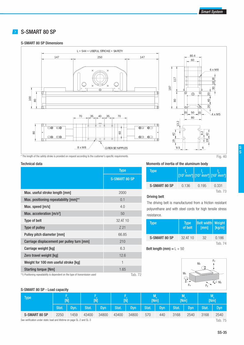
SS-35
Smart System
SS
S-SMART 80 SP
* The length of the safety stroke is provided on request according to the customer's specifi c requirements.
S-SMART 80 SP Dimensions
Type
S-SMART 80 SP
Max. useful stroke length [mm] 2000
Max. positioning repeatability [mm]*1 0.1
Max. speed [m/s] 4.0
Max. acceleration [m/s2] 50
Type of belt 32 AT 10
Type of pulley Z 21
Pulley pitch diameter [mm] 66.85
Carriage displacement per pulley turn [mm] 210
Carriage weight [kg] 6.3
Zero travel weight [kg] 12.6
Weight for 100 mm useful stroke [kg] 1
Starting torque [Nm] 1.65
*1) Positioning repeatability is dependent on the type of transmission used
Technical data
Tab. 72
Type Fx
[N]
Fy
[N]
Fz
[N]
Mx
[Nm]
My
[Nm]
Mz
[Nm]
Stat. Dyn. Stat. Dyn Stat. Dyn Stat. Dyn Stat. Dyn Stat. Dyn
S-SMART 80 SP 2250 1459 43400 34800 43400 34800 570 440 3168 2540 3168 2540
S-SMART 80 SP - Load capacity
See verifi cation under static load and lifetime on page SL-2 and SL-3 Tab. 75
Type Ix
[107 mm4]
Iy
[107 mm4]
Ip
[107 mm4]
S-SMART 80 SP 0.136 0.195 0.331
Type Type
of belt
Belt width
[mm]
Weight
[kg/m]
S-SMART 80 SP 32 AT 10 32 0.186
Moments of inertia of the aluminum body
Driving belt
The driving belt is manufactured from a friction resistant
polyurethane and with steel cords for high tensile stress
resistance.
Tab. 73
Tab. 74
Fig. 40
Fx
MzFz
Mx
FyMy
GREASE NIPPLES
L = 544 + USEFUL STROKE + SAFETY
250 147147
80100
70 35 40 35 7060
8 x M8
80
50
40
4 x M5
80.460
3018
18
6 x M8
2020
1515
80
8011
7
197
4219 19
42
9.5 6
8.2
13.2
Belt length (mm) = L + 50

SS-36
Tab. 76
Fig. 41
Lubrication
SP linear units with ball bearing guides
The ball bearing carriages of the SP versions are fi tted with a retention
cage that eliminates "steel-steel" contact between adjacent revolving
parts and prevents misalignment of these in the circuits.
This system guarantees a long interval between maintenances: SP ver-
sion: every 5000 km or 1 year of use, based on the value reached fi rst. If
S-SMART
Type Quantity of Grease
(g)
S-SMART 50 2
S-SMART 65 2
S-SMART 80 5-6
a longer service life is required or in case of high dynamic or high loaded
applications please contact our offi ces for further verifi cation.
■ Insert the tip of the grease gun into the specifi c grease blocks.
■ Type of lubricant: Lithium soap grease of class NLGI 2.
■ For specially stressed applications or hostile environmental conditions,
lubrication should be applied out more frequently.
Contact Rollon for further advice
3 S-SMART series
Quantity of lubricant necessary for re-lubrication:

SS-37
Smart System
SS
Hollow shaft
Hollow shaft type FP - Standard supply
Units (mm)
Fig. 43
Tab. 78
An (optional) connection fl ange is
required to fi t the standard reduc-
tion units selected by Rollon.
For further information contact our
offi ces.
Applicable
to unit
Shaft
type
D1 D2 D3 E F Drive
head code
S-SMART 50 FP 26 26H7 47J6 75 2.5 M5 2YA
S-SMART 65 FP 34 34H7 62J6 96 2.5 M6 2YA
S-SMART 80 FP 41 41H7 72J6 100 5 M6 2ZA
Ø D2
E
Ø D3Ø D14 x Ø F
Applicable
to unit
Shaft type B D1 AS Assembly
kit code
S-SMART 50 AS 12 26 12h7 G000652
S-SMART 65 AS 15 35 15h7 G000851
S-SMART 80 AS 20 40 20h7 G000828
Simple shafts
AS type simple shafts
Units (mm)
Position of the simple shaft can be to the right or to the left of the drive head. Fig. 42
Tab. 77
This head confi guration is obtained by utilizing an assembly kit delivered
as a separate accessory item.
Shaft can be installed on the left or right side of the drive head as decided
by the customer.
B
D1
D1
B

SS-38
Accessories
The ball bearing guide linear drive system of Rollon SMART System se-
ries linear units enables them to support loads in any direction. They can
therefore be installed in any position.
To install the SMART System series units, we recommend use of one of
the systems indicated below:
T-nuts
Hole Length Code
Rollon
S-SMART 50 M4 8 1001046
S-SMART 65 M5 10 1000627
S-SMART 80 M6 13 1000043
Units (mm)
Fig. 44 Tab. 79
Proximity
Units (mm)
Fig. 45
Tab. 80
B4 B5 L4 L5 H4 H5 For
proximity
Sensor dog
code
Sensor proximity
housing code
S-SMART 50 30 30 30 30 15 30 Ø 8/12 G000835 G000834
S-SMART 65 30 30 30 30 15 30 Ø 8/12 G000836 G000834
S-SMART 80 30 30 30 30 15 30 Ø 8/12 G000837 G000834
Sensor proximity housing kit
Sensor dog
B4
H5B5
L4
L5H4
Proximity switch holder
Aluminum block equipped with T-nuts for fi xing
Proximity switch runner
Iron plate mounted on the carriage used for the proximity operation
Steel nuts to be used in the slots of the body.
3 S-SMART series
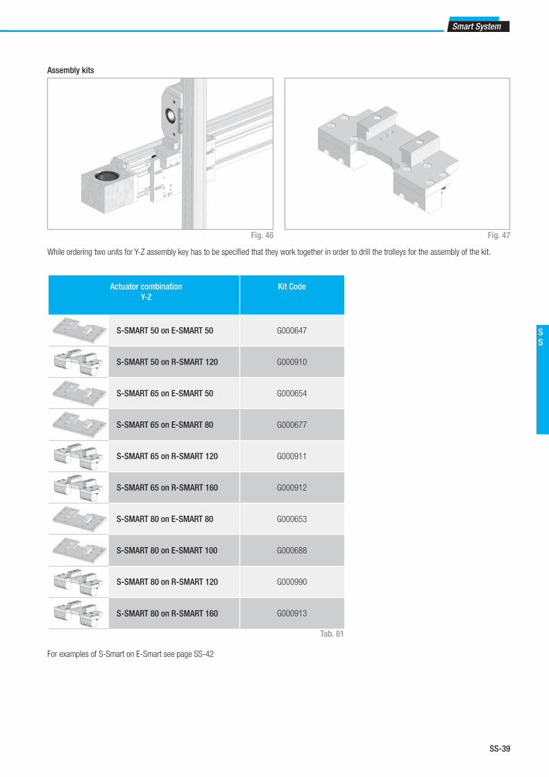
SS-39
Smart System
SS
Actuator combination
Y-Z
Kit Code
S-SMART 50 on E-SMART 50 G000647
S-SMART 50 on R-SMART 120 G000910
S-SMART 65 on E-SMART 50 G000654
S-SMART 65 on E-SMART 80 G000677
S-SMART 65 on R-SMART 120 G000911
S-SMART 65 on R-SMART 160 G000912
S-SMART 80 on E-SMART 80 G000653
S-SMART 80 on E-SMART 100 G000688
S-SMART 80 on R-SMART 120 G000990
S-SMART 80 on R-SMART 160 G000913
Tab. 81
Fig. 46 Fig. 47
Assembly kits
While ordering two units for Y-Z assembly key has to be specifi ed that they work together in order to drill the trolleys for the assembly of the kit.
For examples of S-Smart on E-Smart see page SS-42
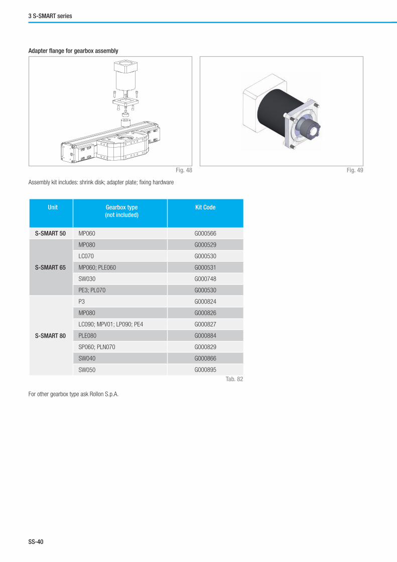
SS-40
Unit Gearbox type
(not included)
Kit Code
S-SMART 50 MP060 G000566
S-SMART 65
MP080 G000529
LC070 G000530
MP060; PLE060 G000531
SW030 G000748
PE3; PL070 G000530
S-SMART 80
P3 G000824
MP080 G000826
LC090; MPV01; LP090; PE4 G000827
PLE080 G000884
SP060; PLN070 G000829
SW040 G000866
SW050 G000895
Tab. 82
Fig. 48 Fig. 49
Adapter fl ange for gearbox assembly
Assembly kit includes: shrink disk; adapter plate; fi xing hardware
For other gearbox type ask Rollon S.p.A.
3 S-SMART series

SS-41
Smart System
SS
Identifi cation codes for the S-SMART linear unit
Ordering key
F 08
05 = 50
06 = 65
08 = 80
2ZA 1300 1A
1A=SP
Linear motion system see pg. SS-31
L=total length of the unit
Drive head code see pg. SS-36
Linear unit type see from pg. SS-32 to pg. SS-34
Linear unit series S-SMART see pg. SS-29
In order to create identifi cation codes for Actuator Line, you can visit: http://confi gureactuator.rollon.com

SS-42
One axis system
Three axis - X-Y-Z system
Two axis Y-Z system
Two parallel axis system
A C
B D
A - X Axis: E-SMART C - Linear units: Y Axis 2 E-SMART - Z Axis 1 S-SMART
Connection kit:
Connection plate Kit for S-SMART (Z axis) on 2 E-SMART (Y axis)
B - Linear units: 2 E-SMART
Connection kit: Parallel Kit
D - Linear units: X Axis 2 E-SMART - Y Axis 2 E-SMART - Z Axis 1 S-SMART
Connection kit: 2 fi xing brackets Kit for 2 E-SMART (X axis) on
2 E-SMART (Y axis). Connection plate Kit for S-SMART (Z axis) on
2 E-SMART (Y axis). Parallel Kit
Multiaxis systems
Previously, customers wishing to build multiaxis units have had to design,
draw and manufacture all the elements necessary to assemble two or
more axes. Rollon now offers a set of components, including brackets and
plates, to enable multiaxis units to be built.
In addition to the standard elements, Rollon can supply plates for special
applications.
Application examples:
Multiaxis systems

SS-43
Smart System
SS
Three axis X-Y-Z systemTwo axis Y-Z system
E F
E - Linear units: Y Axis 1 R-SMART - Z Axis 1 S-SMART
Connection kit: Connection plate Kit for S-SMART (Z axis) on
R-SMART (Y axis). Parallel Kit
F - Linear units: X Axis 2 E-SMART - Y Axis 1 R-SMART - Z Axis 1 S-SMART
Connection kit: 2 fi xing brackets Kit for 2 R-SMART (Y axis) on
2 E-SMART (X axis). Connection plate Kit for S-SMART (Z axis) on
2 R-SMART (Y axis). Parallel Kit


Eco System
FrontespizioEcoSystem.indd 1 22/11/2014 16:30:23

ES-2
1 ECO series
The ECO SYSTEM units are linear actuators made of a self-supporting
extruded aluminum frame and are driven by a polyurethane belt with AT
metric profi le steel inserts.
■ Three different sizes available: 60mm, 80mm, 100mm
■ Version available with recirculating ball bearing or roller rails
■ Reduced weight ensured by the light frame and the aluminum sliders
■ High sliding speed
The ECO SYSTEM series actuators are offered with two motion systems:
ECO SYSTEM – SP
Featuring a maintenance free recirculating linear guide rail fi tted inside
the profi le.
ECO SYSTEM – CI
Featuring four rollers with a Gothic arch outer profi le sliding on hardened
steel bars placed inside the profi le.
ECO series description
Fig. 1
ECO series

ES-3
Eco System
ES
The components
General data about aluminum used: AL 6060
Chemical composition [%]
Physical characteristics
Mechanical characteristics
AI Mg Si Fe Mn Zn Cu Impurites
Remainder 0.35-0.60 0.30-0.60 0.30 0.10 0.10 0.10 0.05-0.15
Density Coeff. of
elasticity
Coeff. of thermal expansion
(20°-100°C)
Thermal conductivity
(20°C)
Specifi c heat
(0°-100°C)
Resistivity Melting point
kg___
dm3
kN___
mm2
10-6
___
K
W_____
m . K
J_____
kg . K
Ω . m . 10-9 °C
2.70 69 23 200 880-900 33 600-655
Rm Rp (02) A HB
N___
mm2
N___
mm2
% __
205 165 10 60-80
Tab. 1
Tab. 2
Tab. 3
Extruded bodies
The anodised aluminum extrusion used for the profi le of the Rollon ECO
series linear units was designed and manufactured by industry experts
to optimise weight while maintaining mechanical strength. The anodised
aluminum alloy 6060 used (see physical-chemical characteristics below)
was extruded with dimensional tolerances complant with EN 755-9 stand-
ards.
Driving belt
The Rollon ECO series linear units use steel reinforced polyurethane
drive belts with AT pitch. This belt is ideal due to its high load transmis-
sion characteristics, compact size and low noise. Used in conjunction
with a backlash-free pulley, smooth alternating motion can be achieved.
Optimisation of the maximum belt width/body dimension ratio enables the
following performance characteristics to be achieved:
■ High speed
■ Low noise
■ Low wear
The driving belt is guided by specifi c slots in the aluminum extruded body
thus covering the inside components.
Carriage
The carriage of the Rollon ECO series linear units is made of anodised
aluminum. Two different length carriages are available for each type of
linear unit.
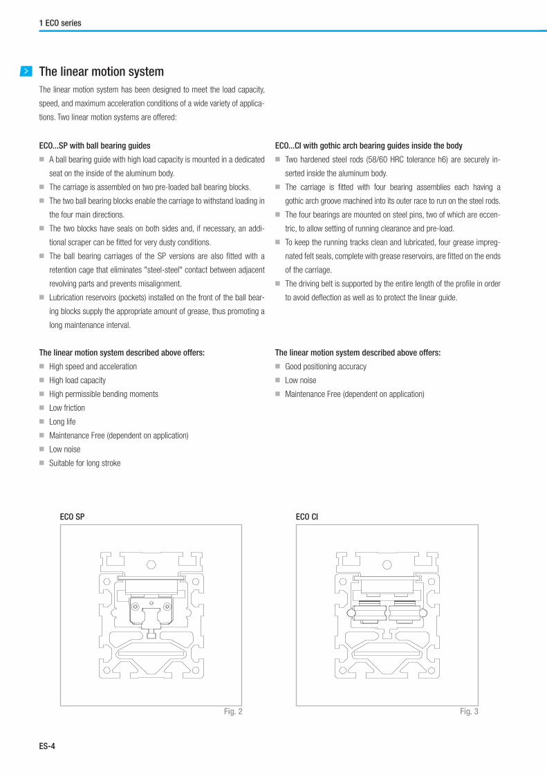
ES-4
1 ECO series
The linear motion system
The linear motion system has been designed to meet the load capacity,
speed, and maximum acceleration conditions of a wide variety of applica-
tions. Two linear motion systems are offered:
ECO...SP with ball bearing guides
■ A ball bearing guide with high load capacity is mounted in a dedicated
seat on the inside of the aluminum body.
■ The carriage is assembled on two pre-loaded ball bearing blocks.
■ The two ball bearing blocks enable the carriage to withstand loading in
the four main directions.
■ The two blocks have seals on both sides and, if necessary, an addi-
tional scraper can be fi tted for very dusty conditions.
■ The ball bearing carriages of the SP versions are also fi tted with a
retention cage that eliminates "steel-steel" contact between adjacent
revolving parts and prevents misalignment.
■ Lubrication reservoirs (pockets) installed on the front of the ball bear-
ing blocks supply the appropriate amount of grease, thus promoting a
long maintenance interval.
The linear motion system described above offers:
■ High speed and acceleration
■ High load capacity
■ High permissible bending moments
■ Low friction
■ Long life
■ Maintenance Free (dependent on application)
■ Low noise
■ Suitable for long stroke
ECO...CI with gothic arch bearing guides inside the body
■ Two hardened steel rods (58/60 HRC tolerance h6) are securely in-
serted inside the aluminum body.
■ The carriage is fi tted with four bearing assemblies each having a
gothic arch groove machined into its outer race to run on the steel rods.
■ The four bearings are mounted on steel pins, two of which are eccen-
tric, to allow setting of running clearance and pre-load.
■ To keep the running tracks clean and lubricated, four grease impreg-
nated felt seals, complete with grease reservoirs, are fi tted on the ends
of the carriage.
■ The driving belt is supported by the entire length of the profi le in order
to avoid defl ection as well as to protect the linear guide.
The linear motion system described above offers:
■ Good positioning accuracy
■ Low noise
■ Maintenance Free (dependent on application)
ECO SP ECO CI
Fig. 2 Fig. 3

ES-5
Eco System
ES
ECO 60 SP2 - ECO 60 CI
* The length of the safety stroke is provided on request according to the customer's specifi c requirements.
ECO 60 SP2 - ECO 60 CI Dimensions
Fig. 4
84
70
84
70
34.5
34.5
L = 188 + C + USEFUL STROKE + SAFETY
80 80
10 10
5.3
10.5
8.53
A (2.5:1)B (5:1)
6.7
7
10.5
4.5
(2.5:1)C
4058
60
73
15 30 15
1530
15
60
B
A
Type
ECO 60 SP2 ECO 60 CI
Max. useful stroke length [mm] 3700 6000
Max. positioning repeatability [mm]*1 ± 0.05 ± 0.05
Max. speed [m/s] 4.0 1.5
Max. acceleration [m/s2] 50 1.5
Type of belt 32 AT 5 32 AT 5
Type of pulley Z 28 Z 28
Pulley pitch diameter [mm] 44.56 44.56
Carriage displacement per pulley turn [mm] 140 140
Carriage weight [kg] 0.51 0.80
Zero travel weight [kg] 3.5 3.2
Weight for 100 mm useful stroke [kg] 0.45 0.68
Starting torque [Nm] 0.24 0.32
Moment of inertia of pulleys [g mm2] 163.000 163.000
*1) Positioning repeatability is dependant on the type of transmission used
Technical data
Tab. 4
ECO 60 SP2 C=225ECO 60 CI C=225
Type Ix
[107 mm4]
Iy
[107 mm4]
Ip
[107 mm4]
ECO 60 0.037 0.054 0.093
Type Type of
belt
Belt width
[mm]
Weight
kg/m
ECO 60 32 AT 5 32 0.105
Moments of inertia of the aluminum body
Fx
MzFz
Mx
FyMy
Driving belt
The driving belt is manufactured with friction resistant pol-
yurethane, with steel cord reinforcement for high tensile
stress resistance.
Belt length (mm) SP2/CI = 2 x L - 166
Tab. 5
Tab. 6
Type Fx
[N]
Fy
[N]
Fz
[N]
Mx
[Nm]
My
[Nm]
Mz
[Nm]
Stat. Dyn. Stat. Dyn Stat. Dyn Stat. Dyn Stat. Dyn Stat. Dyn
ECO 60 SP2 1360 1020 6930 4616 6930 4616 43 29 319 212 319 212
ECO 60 CI 1360 1020 1480 2540 910 1410 20 30 50 78 82 140
ECO 60 SP2 - ECO 60 CI - Load capacity
See verifi cation under static load and lifetime on page SL-2 and SL-3 Tab. 7

ES-6
1 ECO series
ECO 80 SP2 - ECO 80 SP1 - ECO 80 CI
* The length of the safety stroke is provided on request according to the customer's specifi c requirements.
ECO 80 SP2 - ECO 80 SP1 - ECO 80 CI Dimensions
Fig. 5
Type
ECO 80
SP2
ECO 80
SP1
ECO 80
CI
Max. useful stroke length [mm] 6000 6000 6000
Max. positioning repeatability [mm]*1 ± 0.05 ± 0.05 ± 0.05
Max. speed [m/s] 5.0 5.0 1.5
Max. acceleration [m/s2] 50 50 1.5
Type of belt 50 AT 5 50 AT 5 50 AT 5
Type of pulley Z 37 Z 37 Z 37
Pulley pitch diameter [mm] 58.89 58.89 58.89
Carriage displacement per pulley turn [mm] 185 185 185
Carriage weight [kg] 1.6 0.9 2.1
Zero travel weight [kg] 7.7 5.9 8.2
Weight for 100 mm useful stroke [kg] 0.8 0.8 0.65
Starting torque [Nm] 0.75 0.75 0.75
Moment of inertia of pulleys [g mm2] 706.000 706.000 706.000
*1) Positioning repeatability is dependant on the type of transmission used
Technical data
Tab. 8
110
45
110
93 93
48
10 10C
105
105
6.5
13.2
10.53.5
A (2:1)
12.5
4.5
208.2
C (5:1)
9.5
13.2
8.2
6
B (5:1)
78
55
97 8019
4219
204020
BC
A
80
L = 240 + C + USEFUL STROKE + SAFETY
ECO 80 SP1 C=150ECO 80 SP2 C=300ECO 80 CI C=300
Type Ix
[107 mm4]
Iy
[107 mm4]
Ip
[107 mm4]
ECO 80 0.117 0.173 0.280
Type Type of
belt
Belt width
[mm]
Weight
kg/m
ECO 80 50 AT 5 50 0.164
Moments of inertia of the aluminum body
Fx
MzFz
Mx
FyMy
Driving belt
The driving belt is manufactured with friction resistant pol-
yurethane, with steel cord reinforcement for high tensile
stress resistance.
Belt length (mm) SP2/CI = 2 x L - 240
SP1= 2 x L - 90
Tab. 9
Tab. 10
Type Fx
[N] Fy [N] F
z [N] M
x [Nm] M
y [Nm] M
z [Nm]
Stat. Dyn. Stat. Dyn Stat. Dyn Stat. Dyn Stat. Dyn Stat. Dyn
ECO 80 SP2 2120 1590 24200 14560 24200 14560 240 138 1706 1026 1706 1026
ECO 80 SP1 2120 1590 12100 7280 12100 7280 120 69 66 37 66 37
ECO 80 CI 2120 1590 3800 7340 2470 4080 68 110 210 340 320 610
ECO 80 SP2 - ECO 80 SP1 - ECO 80 CI - Load capacity
See verifi cation under static load and lifetime on page SL-2 and SL-3 Tab. 11

ES-7
Eco System
ES
ECO 100 SP2 - ECO 100 SP1 - ECO 100 CI
* The length of the safety stroke is provided on request according to the customer's specifi c requirements.
ECO 100 SP2 - ECO 100 SP1 - ECO 100 CI Dimensions
Fig. 6
Type
ECO 100
SP2
ECO 100
SP1
ECO100
CI
Max. useful stroke length [mm] 6000 6000 6000
Max. positioning repeatability [mm]*1 ± 0.05 ± 0.05 ± 0.05
Max. speed [m/s] 5.0 5.0 1.5
Max. acceleration [m/s2] 50 50 1.5
Type of belt 50 AT 10 50 AT 10 50 AT 10
Type of pulley Z 24 Z 24 Z 24
Pulley pitch diameter [mm] 76.39 76.39 76.39
Carriage displacement per pulley turn [mm] 240 240 240
Carriage weight [kg] 2.9 1.5 3.3
Zero travel weight [kg] 16.7 12.5 17.1
Weight for 100 mm useful stroke [kg] 1.3 1.3 1.1
Starting torque [Nm] 1.90 1.35 1.35
Moment of inertia of pulleys [g mm2] 2070.000 2070.000 2070.000
*1) Positioning repeatability is dependant on the type of transmission used
Technical data
Tab. 12
Type Ix
[107 mm4]
Iy
[107 mm4]
Ip
[107 mm4]
ECO 100 0.342 0.439 0.781
Type Type of
belt
Belt width
[mm]
Weight
kg/m
ECO 100 50 AT 10 50 0.290
Moments of inertia of the aluminum body
Fx
MzFz
Mx
FyMy
Driving belt
The driving belt is manufactured with friction resistant pol-
yurethane, with steel cord reinforcement for high tensile
stress resistance.
Belt length (mm) SP1 = 2 x L - 112
SP2/CI = 2 x L - 312
Tab. 13
Tab. 14
Type Fx
[N] Fy [N] F
z [N] M
x [Nm] M
y [Nm] M
z [Nm]
Stat. Dyn. Stat. Dyn Stat. Dyn Stat. Dyn Stat. Dyn Stat. Dyn
ECO 100 SP2 4410 3310 43400 34800 43400 34800 570 440 4297 3445 4297 3445
ECO 100 SP1 4410 3310 21700 17400 21700 17400 285 220 155 120 155 120
ECO 100 CI 4410 3310 8500 17000 4740 8700 160 300 520 950 930 1850
ECO 100 SP2 - ECO 100 SP1 - ECO 100 CI - Load capacity
See verifi cation under static load and lifetime on page SL-2 and SL-3 Tab. 15
58
58
116
140140
116
C 1010
130
130
A (2:1)
8.3
16.3
134.5
12.5
4.5
208.2
C (5:1)
12
8.5
11.3 18
B (5:1)
70
98
10012
1
30 40 30
2452
24
100
B
C
A
(2:1)
L = 300 + C + USEFUL STROKE + SAFETY
ECO 100 SP1 C=200ECO 100 SP2 C=400ECO 100 CI C=400

ES-8
1 ECO series
Unit Shaft type D1 D2 D3 L Key way
BxH
F G Drive
head code
ECO 60 AC 12 12H7 60J6 75 3.5 4 x 4 M5 12 2A
ECO 80 AC 19 19H7 80J6 100 3.5 6 x 6 M6 16 2A
ECO 100 AC 25 25H7 110J6 130 4.5 8 x 7 M8 20 2A
Hollow shafts
Hollow shafts
Fig. 8
Tab. 17
Transmission of torque to the drive pulley
Torque is transmitted to the drive pulley from a hollow shaft and keyway.
This system may create backlash in the case of alternating loads and high
level acceleration. For further information, contact our offi ces.
An (optional) connection fl ange is
required to fi t the standard reduc-
tion units selected by Rollon.
For further information, contact
our offi ces
Applicable
to unit
Shaft type D1 D2 D3 l2 F G Head code
AS left
Head code
AS right
ECO 60 AS 12 12 60 75 25 M5 12 2G 2I
ECO 80 AS 20 20 80 100 36.5 M6 16 2G 2I
ECO 100 AS 25 25 110 130 50 M8 20 2G 2I
Simple shafts
AS type simple shafts
Hollow shaft
Dimensions (mm)
Position of the simple shaft can be to the left or right of the drive head. Fig. 7
Tab. 16
N° 4 FxG
Ø D2 H7
Ø D3
Ø D1 h7
I2
Ø D1 h7
I2
FxG - N.4
H7ØD1
Ø D3
ØD2
Keyway BxH
L

ES-9
Eco System
ES
Linear units in parallel
Tab. 18
Synchronisation kit for use of ECO linear units in parallel
When movement consisting of two linear units in parallel is essential, a
synchronisation kit must be used. The kit contains original Rollon blade
type precision joints complete with tapered splines and hollow aluminum
drive shafts.
Unit Shaft type D1 D2 D3 Code Formula for length
calculation
ECO 60 AP 12 12 25 45 GK12P...1A L= X-88 [mm]
ECO 80 AP 20 20 40 69.5 GK20P...1A L= X-116 [mm]
ECO 100 AP 25 25 70 99 GK25P...1A L= X-165 [mm]
Fig. 9 Fig. 10
Fig. 11
Ø D
1
Ø D
3
Ø D
2
Ø D
1
L
X
Accessories
Fixing by brackets
The linear motion systems used for the Rollon ECO series linear units
enables them to support loads in any direction. They can therefore be
installed in any position.
To install the units, we recommend use of the dedicated T-slots in the
aluminum extruded bodies as shown below.
A BTab. 19
Unit A
(mm)
B
(mm)
ECO 60 72 30
ECO 80 94 40
ECO 100 120 40

ES-10
1 ECO series
Fig. 12
Tab. 20
Unit A H1 B C E F D1 D2 L L1 Code
ECO 60 20 17.5 6 16 11.5 6 9.4 5.3 50 25 1001490
ECO 80 20 20.7 7 16 14.7 7 11 6.4 50 25 1001491
ECO 100 36.5 28.5 10 31 18.5 11.5 16.5 10.5 100 50 1001233
AD1
F
H1
B
D2
C
E
LL1
Fixing brackets
Anodised aluminum block for fi xing the linear units through the side slots of the body
Fig. 13Tab. 21
T-nuts
Unit D3 D4 G H2 K Code
ECO 60 L 6.7 M5 2.3 6.5 10 1000627
ECO 60 C - M5 - 5 10 1000620
ECO 80 L 8 M6 3.3 8.3 13 1000043
ECO 80 C - M6 - 5.8 13 1000910
ECO 80 I - M6 - 6.5 17 1000911
ECO 100 L 11 M8 3 11 17 1000932
ECO 100 C - M8 - 8 16 1000942
ECO 100 I - M8 - 6.5 17 1000943
Dimensions (mm)
L = Side - C = Carriage - I = Lower
K
D4
H2
D3
G
Steel nuts to be used in the slots of the body.

ES-11
Eco System
ES
Fig. 14
Tab. 22
Sensor proximity housing kit
Anodized aluminum block, red colour, equipped with T-nuts for fi xing into
the body slots.
Sensor dog
L-shaped bracket in zinc-plated iron, mounted on the carriage and used
for the proximity switch operation.
Unit B4 B5 L4 L5 H4 H5 For proximity Sensor dog
Code
Sensor proximity
housing kit code
ECO 60 9.5 14 25 29 12 22.5 Ø 8 G000268 G000213
ECO 80 17.2 20 50 40 17 32 Ø 12 G000267 G000209
ECO 100 17.2 20 50 40 17 32 Ø 12 G000267 G000210
B4
F
= =
L5L4
F
B5
H4H5
Sensor dog
Sensor dog
Sensor proximity housing kit
Sensor proximityhousing kit
H5
Proximity

ES-12
Ordering key
Ordering key
Identifi cation codes for the ECO linear unit
C 06
06=60
08=80
10=100
2A O 2000 1A
1A=SP1
2A=SP2
1C=CI
Linear motion system see pg. ES-4
L=total length of the unit
Driving head code see pg. ES-8
Linear unit size see from pg. ES-5 to pg. ES-7
ECO series see pg. ES-2
In order to create identifi cation codes for Actuator Line, you can visit: http://confi gureactuator.rollon.com

ES-13
Eco System
ES
Two axis X-Y system
ECO axis system
A - Linear units: X axis 1 ECO 80
B - Linear units: X axis: 2 ECO 80 - Y axis 1 ECO 80
Connection kit: 2 Kits of fi xing brackets for the ECO 80 unit (Y axis) on the carriages of the ECO 80 units (X axis).
Multiaxis systems
Previously, customers wishing to build multiaxis units have had to design,
draw and manufacture all the elements necessary to assemble two or
more axis. Rollon now offers a set of fi ttings including brackets and cross
plates to enable multiaxis units to be built. In addition to standard ele-
ments, Rollon also provides plates for special applications.
B
A

Uniline System
FrontespizioUnilineSystem.indd 1 22/11/2014 16:32:41
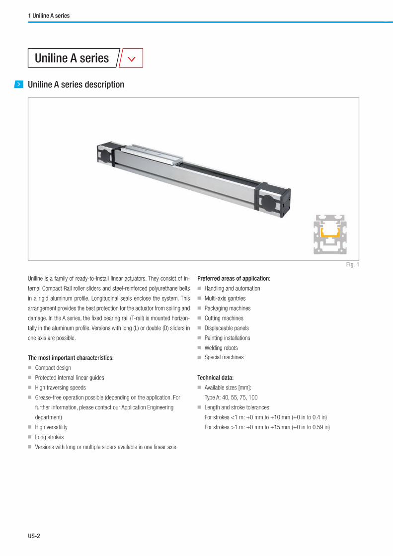
US-2
1 Uniline A series
Uniline A series description
Uniline is a family of ready-to-install linear actuators. They consist of in-
ternal Compact Rail roller sliders and steel-reinforced polyurethane belts
in a rigid aluminum profile. Longitudinal seals enclose the system. This
arrangement provides the best protection for the actuator from soiling and
damage. In the A series, the fixed bearing rail (T-rail) is mounted horizon-
tally in the aluminum profile. Versions with long (L) or double (D) sliders in
one axis are possible.
The most important characteristics:
■ Compact design
■ Protected internal linear guides
■ High traversing speeds
■ Grease-free operation possible (depending on the application. For
further information, please contact our Application Engineering
department)
■ High versatility
■ Long strokes
■ Versions with long or multiple sliders available in one linear axis
Preferred areas of application:
■ Handling and automation
■ Multi-axis gantries
■ Packaging machines
■ Cutting machines
■ Displaceable panels
■ Painting installations
■ Welding robots
■ Special machines
Technical data:
■ Available sizes [mm]:
Type A: 40, 55, 75, 100
■ Length and stroke tolerances:
For strokes <1 m: +0 mm to +10 mm (+0 in to 0.4 in)
For strokes >1 m: +0 mm to +15 mm (+0 in to 0.59 in)
Fig. 1
Uniline A series
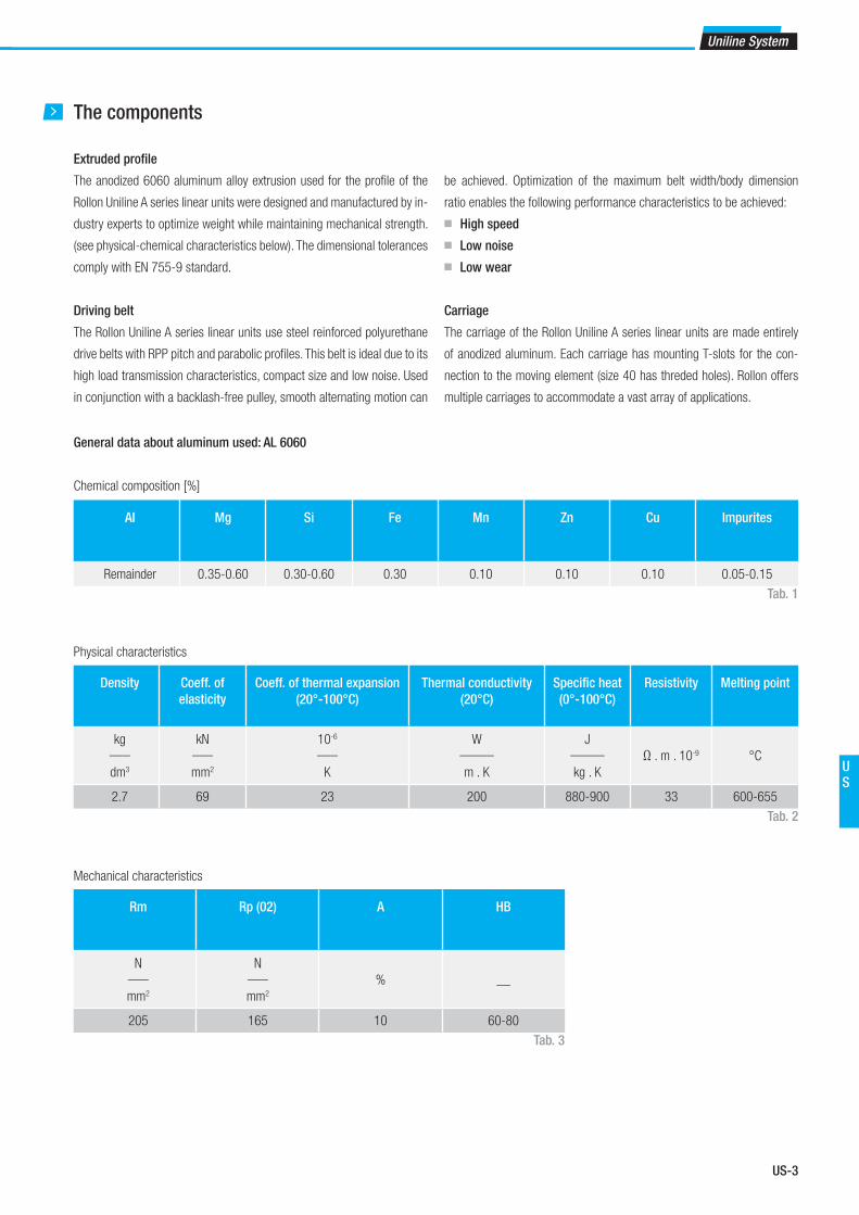
US-3
Uniline System
US
The components
Extruded profi le
The anodized 6060 aluminum alloy extrusion used for the profi le of the
Rollon Uniline A series linear units were designed and manufactured by in-
dustry experts to optimize weight while maintaining mechanical strength.
(see physical-chemical characteristics below). The dimensional tolerances
comply with EN 755-9 standard.
Driving belt
The Rollon Uniline A series linear units use steel reinforced polyurethane
drive belts with RPP pitch and parabolic profi les. This belt is ideal due to its
high load transmission characteristics, compact size and low noise. Used
in conjunction with a backlash-free pulley, smooth alternating motion can
General data about aluminum used: AL 6060
Chemical composition [%]
Physical characteristics
Mechanical characteristics
be achieved. Optimization of the maximum belt width/body dimension
ratio enables the following performance characteristics to be achieved:
■ High speed
■ Low noise
■ Low wear
Carriage
The carriage of the Rollon Uniline A series linear units are made entirely
of anodized aluminum. Each carriage has mounting T-slots for the con-
nection to the moving element (size 40 has threded holes). Rollon offers
multiple carriages to accommodate a vast array of applications.
AI Mg Si Fe Mn Zn Cu Impurites
Remainder 0.35-0.60 0.30-0.60 0.30 0.10 0.10 0.10 0.05-0.15
Density Coeff. of
elasticity
Coeff. of thermal expansion
(20°-100°C)
Thermal conductivity
(20°C)
Specifi c heat
(0°-100°C)
Resistivity Melting point
kg___
dm3
kN___
mm2
10-6
___
K
W_____
m . K
J_____
kg . K
Ω . m . 10-9 °C
2.7 69 23 200 880-900 33 600-655
Rm Rp (02) A HB
N___
mm2
N___
mm2
% __
205 165 10 60-80
Tab. 1
Tab. 2
Tab. 3

US-4
A40
A40 system
Fig. 2
Type A
[mm]
B
[mm]
C*
[mm]
E
[mm]
F
[mm]
G*
[mm]
H
[mm]
I
[mm]
J
[mm]
K
[mm]
M
[mm]
N
[mm]
S
[mm]
V
[mm]
W
[mm]
Z
[mm]
Stroke**
[mm]
A40 40 51.5 57 43.5 20 26 14 Ø 14,9 5 30 2.3 Ø 32 165 0.5 39 91.5 1900
Tab. 4
Z Slider S Stroke** ZL
42,5 80
7,5
15
4 M4 threads
A
AB
J KH
9
16,5
8,2
2,2
F
EC G
A
A
Bore diameter *
V W V
I
MA
M
AF
N
Section A-A
* For information on the motor connection bores, see ordering key. ** The length of the safety stroke is provided on request according to the customer's specifi c requirements.
* The length of the safety stroke is provided on request according to the customer's specifi c requirements.
* The length of the safety stroke is provided on request according to the customer's specifi c requirements.
* For the position of the T-nuts when using our motor adapter plates, see pg. US-15ff
** Maximum stroke for a single-piece guiding rail. For longer strokes, see tab. 9
A40L with long slider
Fig. 3
Fig. 4
Type Smin
[mm]
Smax
[mm]
Sn
[mm]
Z
[mm]
Stroke*
[mm]
A40L 240 400 Sn = Smin
+ n · 10 91.5 1660
Tab. 5
42,5 = =
7,5
15
SnZL
Stroke* Z
6 M4 threads
* Maximum stroke for a single-piece guiding rail and a maximum slider plate length Smax
For longer strokes, see tab. 9
A40D with double slider
7,5
15
Z 42,5 80 Slider S Stroke* ZL
Ln
4 M4 threads
4 M4 threads
Type S
[mm]
Lmin
[mm]
Lmax
**
[mm]
Ln
[mm]
Z
[mm]
Stroke*
[mm]
A40D 165 235 1900 Ln = Lmin
+ n · 5 91.5 1660
Tab. 6* Maximum stroke for a single-piece guiding rail and a minimum slider plate distance Lmin
** Maximum distance Lmax
between the centres of slider plates at a stroke of 0 mm
For longer strokes, see tab. 9
1 Uniline A series

US-5
Uniline System
US
A40
Load ratings, moments and characteristic data
Fig. 5
Type C
[N]
C0rad
[N]
C0ax
[N]
Mx
[Nm]
My
[Nm]
Mz
[Nm]
A40 1530 820 300 2.8 5.6 13.1
A40-L 3060 1640 600 5.6 22 to 70 61 to 192
A40-D 3060 1640 600 5.6 70 to 570 193 to 1558
Tab. 8For the calculation of the allowed moments, please observe pages SL-5ff
C0ax
My
Mz
Mx
C0rad
Technical dataType
A40
Standard belt tension [N] 160
Moment at no load [Nm] 0.14
Max. traversing speed [m/s] 3
Max. acceleration [m/s²] 10
Repeat accuracy [mm] 0.1
Linear accuracy [mm] 0.8
Compact Rail guiding rail TLV18
Slider type CS18 spec.
Moment of inertia Iy [cm4] 12
Moment of inertia Iz [cm4] 13.6
Pitch diameter of pulley [m] 0.02706
Moment of inertia of each pulley [gmm²] 5055
Stroke per shaft revolution [mm] 85
Mass of slider [g] 220
Weight with zero stroke [g] 1459
Weight with 1 m stroke [g] 3465
Max. stroke [mm] 3500
Working temperature from -20 °C to + 80 °C
Tab. 9
Tab. 7
Type Type of belt Belt width
[mm]
Weight
kg/m
A40 10RPP5 10 0.041
Driving belt
The driving belt is manufactured from a friction resistant polyurethane and
with steel cords for high tensile stress resistance.
Belt length (mm) = 2 x L - 168 Standard slider
Belt length (mm) = 2 x L - Sn-3 Long slider
Belt length (mm) = 2 x L - Ln - 168 Double slider

US-6
A55 system
Z Slider S Stroke** ZL
Type A
[mm]
B
[mm]
C*
[mm]
D
[mm]
E
[mm]
F
[mm]
G*
[mm]
H
[mm]
I
[mm]
J
[mm]
K
[mm]
M
[mm]
N
[mm]
S
[mm]
X
[mm]
Y
[mm]
V
[mm]
W
[mm]
Z
[mm]
Stroke**
[mm]
A55 55 71 67.5 25 50.5 27.5 32.5 15 Ø 24.9 1.5 52 2.35 Ø 47 200 28 12 0.5 54 108 3070
GCE
F
A
A
Bore diameter *
IN
MA
M
FA
V W VSection A-A
A
A BJ K
Y X
HD
2,2
16,5
9
8,2
Z Slider S Slider S Stroke* Z
Ln
L
A55
Fig. 6
Tab. 10
* For information on the motor connection bores, see ordering key. ** The length of the safety stroke is provided on request according to the customer's specifi c requirements.
A55L with long slider
Fig. 7
Fig. 8
Type Smin
[mm]
Smax
[mm]
Sn
[mm]
Z
[mm]
Stroke*
[mm]
A055-L 310 500 Sn = Smin
+ n · 10 108 2770
Tab. 11
A55D with double slider
Type S
[mm]
Lmin
[mm]
Lmax
**
[mm]
Ln
[mm]
Z
[mm]
Stroke*
[mm]
A55D 200 300 3070 Ln = Lmin
+ n · 5 108 2770
Tab. 12* Maximum stroke for a single-piece guiding rail and a minimum slider plate distance Lmin
** Maximum distance Lmax
between the centres of slider plates at a stroke of 0 mm
For longer strokes, see tab. 15
Z Sn ZL
Stroke*
1 Uniline A series
* The length of the safety stroke is provided on request according to the customer's specifi c requirements.
* The length of the safety stroke is provided on request according to the customer's specifi c requirements.
* For the position of the T-nuts when using our motor adapter plates, see pg. US-15ff
** Maximum stroke for a single-piece guiding rail. For longer strokes, see tab. 15
* Maximum stroke for a single-piece guiding rail and a maximum slider plate length Smax
For longer strokes, see tab. 15

US-7
Uniline System
US
A55
Load ratings, moments and characteristic data
Fig. 9
Type C
[N]
C0rad
[N]
C0ax
[N]
Mx
[Nm]
My
[Nm]
Mz
[Nm]
A55 4260 2175 750 11.5 21.7 54.4
A55-L 8520 4350 1500 23 82 to 225 239 to 652
A55-D 8520 4350 1500 23 225 to 2302 652 to 6677
Tab. 14For the calculation of the allowed moments, please observe pages SL-5ff
C0ax
My
Mz
Mx
C0rad
Technical dataType
A55
Standard belt tension [N] 220
Moment at no load [Nm] 0.22
Max. traversing speed [m/s] 5
Max. acceleration [m/s²] 15
Repeat accuracy [mm] 0.1
Linear accuracy [mm] 0.8
Compact Rail guiding rail TLV28
Slider type CS28 spec.
Moment of inertia Iy [cm4] 34.6
Moment of inertia Iz [cm4] 41.7
Pitch diameter of pulley [m] 0.04138
Moment of inertia of each pulley [gmm²] 45633
Stroke per shaft revolution [mm] 130
Mass of slider [g] 475
Weight with zero stroke [g] 2897
Weight with 1 m stroke [g] 4505
Max. stroke [mm] 5500
Working temperature from -20 °C to + 80 °C
Tab. 15
Tab. 13
Type Type of belt Belt width
[mm]
Weight
kg/m
A55 18RPP5 18 0.074
Driving belt
The driving belt is manufactured from a friction resistant polyurethane and
with steel cords for high tensile stress resistance.
Belt length (mm) = 2 x L - 182 Standard slider
Belt length (mm) = 2 x L - Sn+18 Long slider
Belt length (mm) = 2 x L - Ln - 182 Double slider

US-8
A75 system
Type A
[mm]
B
[mm]
C*
[mm]
D
[mm]
E
[mm]
F
[mm]
G*
[mm]
H
[mm]
I
[mm]
J
[mm]
K
[mm]
M
[mm]
N
[mm]
S
[mm]
X
[mm]
Y
[mm]
V
[mm]
W
[mm]
Z
[mm]
Stroke**
[mm]
A75 75 90 71.5 35 53.5 38.8 34.5 20 Ø 29.5 5 65 4.85 Ø 55 285 36 14.5 2.3 70.4 116 3420
1 Uniline A series
A75
Fig. 10
Tab. 16
* For information on the motor connection bores, see ordering key. ** The length of the safety stroke is provided on request according to the customer's specifi c requirements.
A75L with long slider
Fig. 11
Fig. 12
Type Smin
[mm]
Smax
[mm]
Sn
[mm]
Z
[mm]
Stroke*
[mm]
A75-L 440 700 Sn = Smin
+ n · 10 116 3000
Tab. 17* Maximum stroke for a single-piece guiding rail and a maximum slider plate length Smax
For longer strokes, see tab. 21
A75D with double slider
Type S
[mm]
Lmin
[mm]
Lmax
**
[mm]
Ln
[mm]
Z
[mm]
Stroke*
[mm]
A75D 285 416 3416 Ln = Lmin
+ n · 8 116 3000
Tab. 18* Maximum stroke for a single-piece guiding rail and a minimum slider plate distance Lmin
** Maximum distance Lmax
between the centres of slider plates at a stroke of 0 mm
For longer strokes, see tab. 21
Z Slider S Stroke** ZL
GCE
F
A
A
Bore diameter *
IN
MA
M
FA
V W VSection A-A
A
A BJ K
Y X
HD
2,2
16,5
9
8,2
Z Slider S Slider S Stroke* Z
Ln
L
Z Sn ZL
Stroke*
* The length of the safety stroke is provided on request according to the customer's specifi c requirements.
* The length of the safety stroke is provided on request according to the customer's specifi c requirements.
* For the position of the T-nuts when using our motor adapter plates, see pg. US-15ff
** Maximum stroke for a single-piece guiding rail. For longer strokes, see tab. 21
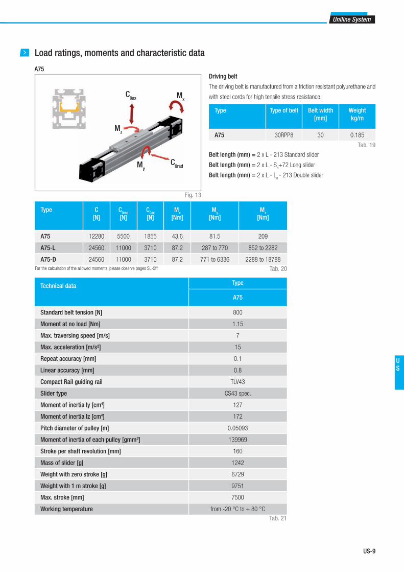
US-9
Uniline System
US
A75
Load ratings, moments and characteristic data
Fig. 13
Type C
[N]
C0rad
[N]
C0ax
[N]
Mx
[Nm]
My
[Nm]
Mz
[Nm]
A75 12280 5500 1855 43.6 81.5 209
A75-L 24560 11000 3710 87.2 287 to 770 852 to 2282
A75-D 24560 11000 3710 87.2 771 to 6336 2288 to 18788
Tab. 20For the calculation of the allowed moments, please observe pages SL-5ff
C0ax
My
Mz
Mx
C0rad
Technical dataType
A75
Standard belt tension [N] 800
Moment at no load [Nm] 1.15
Max. traversing speed [m/s] 7
Max. acceleration [m/s²] 15
Repeat accuracy [mm] 0.1
Linear accuracy [mm] 0.8
Compact Rail guiding rail TLV43
Slider type CS43 spec.
Moment of inertia Iy [cm4] 127
Moment of inertia Iz [cm4] 172
Pitch diameter of pulley [m] 0.05093
Moment of inertia of each pulley [gmm²] 139969
Stroke per shaft revolution [mm] 160
Mass of slider [g] 1242
Weight with zero stroke [g] 6729
Weight with 1 m stroke [g] 9751
Max. stroke [mm] 7500
Working temperature from -20 °C to + 80 °C
Tab. 21
Tab. 19
Type Type of belt Belt width
[mm]
Weight
kg/m
A75 30RPP8 30 0.185
Driving belt
The driving belt is manufactured from a friction resistant polyurethane and
with steel cords for high tensile stress resistance.
Belt length (mm) = 2 x L - 213 Standard slider
Belt length (mm) = 2 x L - Sn+72 Long slider
Belt length (mm) = 2 x L - Ln - 213 Double slider

US-10
A100
A100 system
Fig. 14
Z Slider S Stroke* Z
1745
35 35 130 35 8 M8 threads
1L
2
25 20 180 2010
4 M6 threads (on both sides)
Type A
[mm]
A1
[mm]
B
[mm]
D
[mm]
H
[mm]
J
[mm]
K
[mm]
S
[mm]
Z1
[mm]
Z2
[mm]
Stroke*
[mm]
A100 101 105 122.5 45 32.5 10.5 79 300 123 117 3420
Tab. 22* Maximum stroke for a single-piece guiding rail. For longer strokes, see tab. 27
1 Uniline A series
B
AA
KJ
HD
1
20,1
6
10,3
13
* The length of the safety stroke is provided on request according to the customer's specifi c requirements.

US-11
Uniline System
US
A100L with long slider
Fig. 15
10
25 20 284 20 4 M6 threads (on both sides)
1745
35 35 234 35
Z Sn Stroke* Z
8 M8 threads
1L
2
Tab. 23* Maximum stroke for a single-piece guiding rail and a maximum slider plate length Smax
For longer strokes, see tab. 27
A100D with double slider
Fig. 16
Ln
Slider SL
35 35 130 35Slider S
35 35 130 35Stroke*Z Z1 2
Type S
[mm]
Lmin
[mm]
Lmax
**
[mm]
Ln
[mm]
Z1
[mm]
Z2
[mm]
Stroke*
[mm]
A100D 300 396 3396 Ln = Lmin
+ n · 50 123 117 3024
Tab. 24* Maximum stroke for a single-piece guiding rail and a minimum slider plate distance Lmin
** Maximum distance Lmax
between the centres of slider plates at a stroke of 0 mm
For longer strokes, see tab. 27
* The length of the safety stroke is provided on request according to the customer's specifi c requirements.
* The length of the safety stroke is provided on request according to the customer's specifi c requirements.
Type Smin
[mm]
Smax
[mm]
Sn
[mm]
Z1
[mm]
Z2
[mm]
Stroke*
[mm]
A100L 404 404 Sn = Smin
= Smax
123 117 3316

US-12
A100
Load ratings, moments and characteristic data
Fig. 17
Type C
[N]
C0rad
[N]
C0ax
[N]
Mx
[Nm]
My
[Nm]
Mz
[Nm]
A100 30750 12500 7200 250 250 600
A100-L 30750 12500 7200 250 500 1200
A100-D 61500 25000 14400 500 2851 to 24451 4950 to 42450
Tab. 26For the calculation of the allowed moments, please observe pages SL-5ff
C0ax
My
Mz
Mx
C0rad
Technical dataType
A100
Standard belt tension [N] 1000
Moment at no load [Nm] 2.3
Max. traversing speed [m/s] 9
Max. acceleration [m/s²] 20
Repeat accuracy [mm] 0.1
Linear accuracy [mm] 0.8
Compact Rail guiding rail TLV63
Slider type CS63 spec.
Moment of inertia Iy [cm4] 500
Moment of inertia Iz [cm4] 400
Pitch diameter of pulley [m] 0.06048
Moment of inertia of each pulley [gmm²] 330000
Stroke per shaft revolution [mm] 190
Mass of slider [g] 4200
Weight with zero stroke [g] 12700
Weight with 1 m stroke [g] 15950
Max. stroke [mm] 5600
Working temperature from -20 °C to + 80 °C
Tab. 27
1 Uniline A series
Tab. 25
Type Type of belt Belt width
[mm]
Weight
kg/m
A100 36AT10 36 0.220
Driving belt
The driving belt is manufactured from a friction resistant polyurethane and
with steel cords for high tensile stress resistance.
Belt length (mm) = 2 x L - 197 Standard slider
Belt length (mm) = 2 x L + 301 Long slider
Belt length (mm) = 2 x L - Ln - 197 Double slider

US-13
Uniline System
US
A100 motor connection – model A
Motor connection via key
Fig. 18* For information on the motor connection bores, see ordering key
** For information on the motor drive shaft, see chapter Accessories, pg. US-15
4 M6 threads (on both sides)
C C
GG
Bore diameter *A
NI
M
A1
Type A
[mm]
A1
[mm]
C
[mm]
G
[mm]
I
[mm]
M
[mm]
N
[mm]
A100 101 105 32.5 32.5 Ø 39,5 4 Ø 68
Tab. 28
A100 motor connection – model B
Motor connection via Shrink Disk
Fig. 19* See chapter Accessories, pg. US-15
4 M6 threads (on both sides)
GG
C CBore diameter *
A
NI
M
A1

US-14
Lubrication
The raceways of the guide rails in the Uniline linear axes are prelubricated.
To achieve the calculated service life, a lubrication film must always be
present between the raceway and the roller. The lubrication film also pro-
vides anticorrosion protection to the ground raceways. An approximate
value for the lubrication period is every 100 km or every six months. The
recommended lubricant is a lithium-based roller bearing grease of me-
dium consistency.
Lubrication of the raceways
Proper lubrication under normal conditions:
■ reduces friction
■ reduces wear
■ reduces stress on the contact faces
■ reduces running noise
Tab. 29
Lubricants Thickeners Temperature range
[°C]
Dynamic viscosity [mPas]
Roller bearing grease Lithium soap -30 to +170 <4500
Relubrication of the guide rails
These types of rails have a lubricating conduit on the side of the slider
plate (type A100 is equipped with lubricating nipple) through which the
lubricant can be applied directly to the raceways. Lubrication can be done
in one of two ways:
1. Relubrication using a grease gun:
This is done by inserting the tip of the grease gun into the conduit at the
slider plate and injecting the grease inside (see fig. 20). Please note that
the grease has to fill the whole conduit in order to lubricate the rail prop-
erly; for this reason sufficient grease must be used.
2. Automatic lubrication system:
To connect the unit to an automatic greasing system, use a proper adapt-
er/connector* that attaches to the threaded hole on the side of the trolley. Fig. 20
Fig. 21
AA BB
CC
The advantage of this solution is the possibility of rail re-lubrication with-
out machine downtime.
*(Any adapter that may be necessary must be manufactured on site)
Cleaning the guide rails
It is always recommended to clean the slider rail prior to any relubrication,
in order to remove grease residues. This can be done while performing
maintenance work or during a scheduled machine stop.
1. Unscrew the safety screws C (on top of the slider plate) from the belt
tensioning device A (see fig. 21).
2. Also completely unscrew the belt tensioning screws B and remove the
belt tensioning devices A from their housings.
3. Lift the toothed belt until the guide rails can be seen.
Important: Ensure that the side seal is not damaged.
4. Clean the rail raceways with a clean and dry cloth. Ensure that all
grease and dirt residues from previous work processes are removed.
To ensure that the rails are cleaned over their entire length, the slider
plate should be moved once over its entire length.
5. Apply a sufficient amount of grease to the raceways.
1 Uniline A series
6. Re-insert the belt tensioning devices A into their housings and mount
the belt tensioning screws B. Re-adjust the belt tension (see pg. US-
63).
7. Fasten the safety screws C.
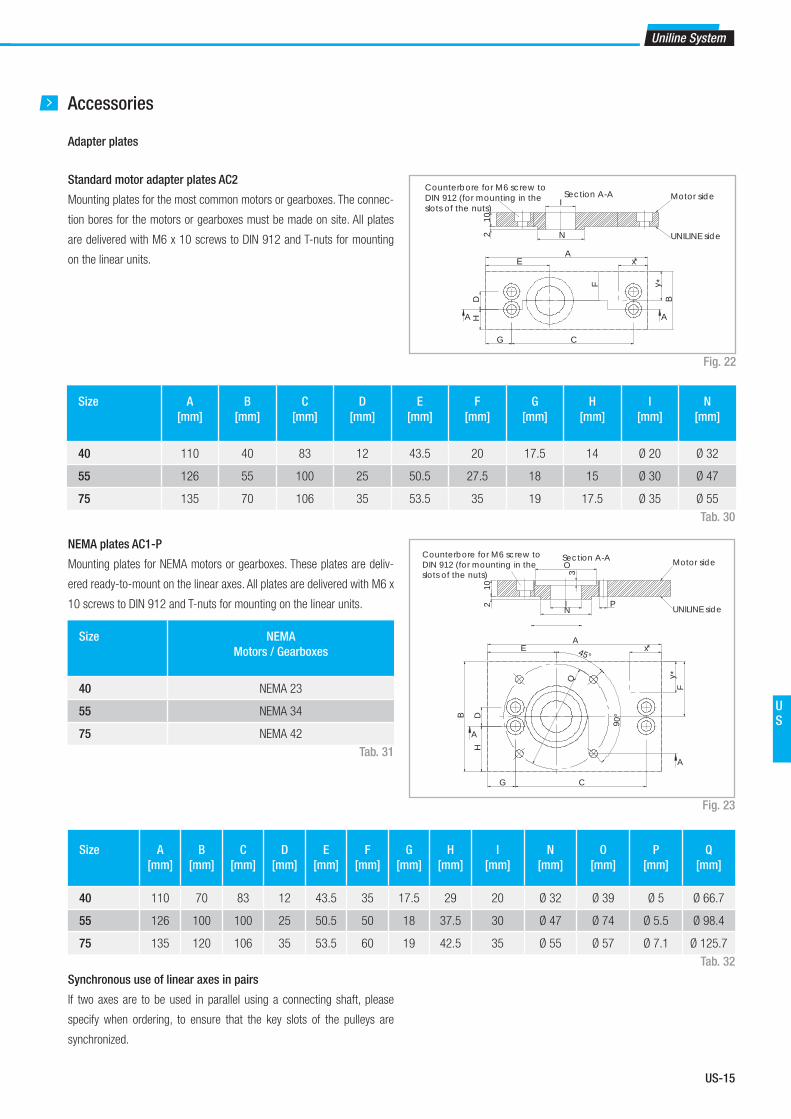
US-15
Uniline System
US
Accessories
Adapter plates
Standard motor adapter plates AC2
Mounting plates for the most common motors or gearboxes. The connec-
tion bores for the motors or gearboxes must be made on site. All plates
are delivered with M6 x 10 screws to DIN 912 and T-nuts for mounting
on the linear units.
Size A
[mm]
B
[mm]
C
[mm]
D
[mm]
E
[mm]
F
[mm]
G
[mm]
H
[mm]
I
[mm]
N
[mm]
40 110 40 83 12 43.5 20 17.5 14 Ø 20 Ø 32
55 126 55 100 25 50.5 27.5 18 15 Ø 30 Ø 47
75 135 70 106 35 53.5 35 19 17.5 Ø 35 Ø 55
Fig. 22
Tab. 30
HD
G C
EA
F
B
x
y
A A
*
*
210
N
ISection A-A Motor side
UNILINE side
Counterbore for M6 screw to DIN 912 (for mounting in the slots of the nuts)
NEMA plates AC1-P
Mounting plates for NEMA motors or gearboxes. These plates are deliv-
ered ready-to-mount on the linear axes. All plates are delivered with M6 x
10 screws to DIN 912 and T-nuts for mounting on the linear units.
Fig. 23
Size A
[mm]
B
[mm]
C
[mm]
D
[mm]
E
[mm]
F
[mm]
G
[mm]
H
[mm]
I
[mm]
N
[mm]
O
[mm]
P
[mm]
Q
[mm]
40 110 70 83 12 43.5 35 17.5 29 20 Ø 32 Ø 39 Ø 5 Ø 66.7
55 126 100 100 25 50.5 50 18 37.5 30 Ø 47 Ø 74 Ø 5.5 Ø 98.4
75 135 120 106 35 53.5 60 19 42.5 35 Ø 55 Ø 57 Ø 7.1 Ø 125.7
Tab. 32
Size NEMA
Motors / Gearboxes
40 NEMA 23
55 NEMA 34
75 NEMA 42
Tab. 31 HDB
A
G C
E
F
45°
90°
Q
x
y
A
A
*
*
102 I
N
3O
P
Section A-A Motor side
UNILINE side
Counterbore for M6 screw to DIN 912 (for mounting in the slots of the nuts)
Synchronous use of linear axes in pairs
If two axes are to be used in parallel using a connecting shaft, please
specify when ordering, to ensure that the key slots of the pulleys are
synchronized.

US-16
Fixing brackets APF-2
Fixing clamp (for all sizes except A100) for simple mounting of a linear
axis on a mounting surface or for connecting two units with or without a
connection plate (see pg. US-68).
A spacer* may be necessary.
*(Any spacer that may be necessary must be manufactured on site)
Fig. 24
7,51530
6,52 holes 4,5
Section A-A5
4
208,
5
35
7,3
40
20
A
A
T-nut
The maximum tightening torque is 10 Nm.
Fig. 25
Sizes 40 - 75
A100 double AS
For type A100 with motor connection A only.
Fig. 26
168
Ø19
*
6 x 6 x 25 key slot to DIN 6885 A6 x 6 x 32 key slot to DIN 6885 A
Ø19
*
31,331,3
* Also available with a 20 mm diameter shaft
16,5M6
7,9
A A
1,5
6
Section A-A
A100 conical fi tting device AC-10MA01
For type A100 with motor connection B only.
Fig. 27
Ø19
Ø24
8 106,342,9
M6
Motor Intermediate plate*
RollonFitting device
* Any intermediate plate that may be necessary must be manufactured on site.
The maximum transferrable torque is 63 Nm.
1 Uniline A series

US-17
Uniline System
US
T-connection plate APC-1
T-connection plate allows two units to be mounted perpendicu-
lar to each other (see pg. US-65). The plate will not interfere with
the strokes of either unit. All plates are delivered with M6 x 10
screws to DIN 912 and T-nuts for mounting on the linear units.
Fig. 28
Size Fixing holes
for the slider
Fixing holes
for the profi le
40 Holes 1 Holes 4
55 Holes 2 Holes 5
75 Holes 3 Holes 6
Tab. 33
Size Fixing holes
for the slider
Fixing holes
for the profi le
40 Holes 1 Holes 4
55 Holes 2 Holes 5
75 Holes 3 Holes 6
Tab. 34
Fig. 29
55 55165
150
11 1
1
2
2
2
2
3
3 3
3
4
4
5
5 5
56
6 6
6
Aluminum profile mounting side
Counterbore for M6 screw to DIN 912 (for mounting in the slots of the nuts)
Slider mounting side
Angle connection plate APC-2
allows the right angle mounting of two units. The trolley of one unit can
be mounted to the side of the other (see pg. US-66). The plate will not
interfere with the strokes of either unit. All plates are delivered with M6 x
10 screws to DIN 912 and T-nuts for mounting to the linear units.
Assembly kits
75
165
8
1
1 1
1 2
2
2
2
3
3
3
3
Aluminum profile mounting side
873 4
5566
Slider mounting side
Counterbore for M6 screw to DIN 912 (for mounting in the slots of the nuts)
X connection plate APC-3
X connection plate for mounting two sliders perpendicular to each other
(see pg. US-67). The plate will not interfere with the strokes of either unit.
All plates are delivered with M6 x 10 screws to DIN 912 and T-nuts for
mounting on the linear units.
Fig. 30
Size Fixing holes
for slider 1
Fixing holes
for slider 2
40 Holes 1 Holes 4
55 Holes 2 Holes 5
75 Holes 3 Holes 6
Tab. 35
52,5 55160
52,5
55160 1 1
1 1
2 2
2 23
3 3
3
4 4
4 4
55
556 6
66
10
Counterbore for M6 screw to DIN 912(for mounting in the slots of the nuts)

US-18
Ordering key
Identifi cation code for Uniline linear unit
U A 07
04=40
05=55
07=75
10=100
1A 1190 1A D 500 L 350
Indices of long slider plate
see pg. US-4 - US-6 - US-8 - US-10
Indices of double slider plate, distance of the centers of slider plates
see pg. US-4 - US-6 - US-8 - US-10
Profi le/Rail code
L= Total length of the unit
Driving head code
Size see pg. US-4 - US-6 - US-8 - US-10
Type
Uniline prefi x
Ordering example: UA 07 1A 1190 1A D 500 L 350
Ordering key
In order to create identifi cation codes for Actuator Line, you can visit: http://confi gureactuator.rollon.com

US-19
Uniline System
US
Accessories
Standard motor adapter plate
A 07
04=40
05=55
07=75
10=100
AC2
Standard motor adapter plates see pg. US-15
Size see pg. US-15
Type (except A100)
Ordering example: A07-AC2
NEMA motor adapter plates
A 07
04=40
05=55
07=75
10=100
AC1
NEMA motor adapter plates see pg. US-15
Size see pg. US-15
Type (except A100)
Ordering example: A07-AC1
T-connection plate Order code: APC-1 (for all sizes except A100), s. pg. US-17
Angle connection plate Order code: APC-2 (for all sizes except A100), s. pg. US-17
X connection plate Order code: APC-3 (for all sizes except A100), s. pg. US-17
Fixing clamp Order code: APF-2 (for all sizes except A100), s. pg. US-16
Size
Head
codeHole [Ø] 40 55 75 100
Metric [mm]with slot for key
10G8 / 3js9 12G8 / 4js9 14G8 / 5js9 19G8 / 6js9 1A
10G8 / 3js9 16G8 / 5js9 20G8 / 6js9 2A
14G8 / 5js9 19G8 / 6js9 3A
16G8 / 5js9 4A
Metric [mm]for compression
coupling
18 1B
24 2B
Inch [in]with slot for key
3⁄8 / 1⁄8 1⁄2 / 1⁄8 5⁄8 / 3⁄16 1P
3⁄8 / 1⁄8 2P
5⁄8 / 3⁄16 3P
The highlighted connection bores are standard connections
Metric: key seat for keys to DIN 6885 form A
Inch: key seat for keys to BS 46 Part 1: 1958
Motor connection bores
Tab. 36

US-20
2 Uniline C series
Uniline C series description
Uniline is a family of ready-to-install linear actuators. They consist of in-
ternal Compact Rail roller sliders and steel-reinforced polyurethane belts
in a rigid aluminum profile. Longitudinal seals enclose the system. This
arrangement provides the best protection for the actuator from soiling and
damage. In the C series, the fixed bearing rail (T-rail) and the compensat-
ing bearing rail (U-rail) are mounted in the aluminum profile vertically.
Versions with long (L) or double (D) sliders in one axis are possible.
The most important characteristics:
■ Compact design
■ Protected internal linear guides
■ High traversing speeds
■ Grease-free operation possible (depending on the application. For
further information, please contact our Application Engineering
department)
■ High versatility
■ Long strokes
■ Versions with long or multiple sliders available in one linear axis
Preferred areas of application:
■ Handling and automation
■ Multi-axis gantries
■ Packaging machines
■ Cutting machines
■ Displaceable panels
■ Painting installations
■ Welding robots
■ Special machines
Technical data:
■ Available sizes [mm]:
Type C: 55, 75
■ Length and stroke tolerances:
For strokes <1 m: +0 mm to +10 mm (+0 in to 0.4 in)
For strokes >1 m: +0 mm to +15 mm (+0 in to 0.59 in)
Fig. 31
Uniline C series

US-21
Uniline System
US
The components
Extruded profi le
The anodized 6060 aluminum alloy extrusion used for the profi le of the
Rollon Uniline C series linear units were designed and manufactured by in-
dustry experts to optimize weight while maintaining mechanical strength.
(see physical-chemical characteristics below).The dimensional tolerances
comply with EN 755-9 standard.
Driving belt
The Rollon Uniline C series linear units use steel reinforced polyurethane
drive belts with RPP pitch and parabolic profi les. This belt is ideal due to its
high load transmission characteristics, compact size and low noise. Used
in conjunction with a backlash-free pulley, smooth alternating motion can
General data about aluminum used: AL 6060
Chemical composition [%]
Physical characteristics
Mechanical characteristics
be achieved. Optimization of the maximum belt width/body dimension
ratio enables the following performance characteristics to be achieved:
■ High speed
■ Low noise
■ Low wear
Carriage
The carriage of the Rollon Uniline C series linear units are made entirely
of anodized aluminum. Each carriage has mounting T-slots for the con-
nection to the moving element. Rollon offers multiple carriages to accom-
modate a vast array of applications.
AI Mg Si Fe Mn Zn Cu Impurites
Remainder 0.35-0.60 0.30-0.60 0.30 0.10 0.10 0.10 0.05-0.15
Density Coeff. of
elasticity
Coeff. of thermal expansion
(20°-100°C)
Thermal conductivity
(20°C)
Specifi c heat
(0°-100°C)
Resistivity Melting point
kg___
dm3
kN___
mm2
10-6
___
K
W_____
m . K
J_____
kg . K
Ω . m . 10-9 °C
2.7 69 23 200 880-900 33 600-655
Rm Rp (02) A HB
N___
mm2
N___
mm2
% __
205 165 10 60-80
Tab. 37
Tab. 38
Tab. 39

US-22
Z Slider SL
Stroke** Z
A
A B
J KY X
H
2,2
16,5
9
8,2
C55 system
Type A
[mm]
B
[mm]
C*
[mm]
E
[mm]
F
[mm]
G*
[mm]
H
[mm]
I
[mm]
J
[mm]
K
[mm]
M
[mm]
N
[mm]
S
[mm]
X
[mm]
Y
[mm]
V
[mm]
W
[mm]
Z
[mm]
Stroke**
[mm]
C55 55 71 67.5 50.5 27.5 32.5 15 Ø 24.9 1.5 52 2.35 Ø 47 200 28 12 0.5 54 108 1850
C55
Fig. 32
Tab. 40* For the position of the T-nuts when using our motor adapter plates, see pg. US-27ff
** Maximum stroke for a single-piece guiding rail. For longer strokes, see tab. 45
C55L with long slider
Fig. 33
Fig. 34
Type Smin
[mm]
Smax
[mm]
Sn
[mm]
Z
[mm]
Stroke*
[mm]
C55L 310 500 Sn = Smin
+ n ·10 108 1550
Tab. 41* Maximum stroke for a single-piece guiding rail and a maximum slider plate length Smax
For longer strokes, see tab. 45
C55D with double slider
Type S
[mm]
Lmin
[mm]
Lmax
**
[mm]
Ln
[mm]
Z
[mm]
Stroke*
[mm]
C55D 200 300 1850 Ln = Lmin
+ n · 5 108 1570
Tab. 42* Maximum stroke for a single-piece guiding rail and a minimum slider plate distance Lmin
** Maximum distance Lmax
between the centres of slider plates at a stroke of 0 mm
For longer strokes, see tab. 45
C GE
F
A
A
Bore diameter *
IN
V W V
M MA
AF
Section A-A
ZL
Slider Sn Stroke* Z
ZL
Slider S Slider S Stroke* Z
Ln
2 Uniline C series
* For information on the motor connection bores, see ordering key. ** The length of the safety stroke is provided on request according to the customer's specifi c requirements.
* The length of the safety stroke is provided on request according to the customer's specifi c requirements.
* The length of the safety stroke is provided on request according to the customer's specifi c requirements.

US-23
Uniline System
US
Load ratings, moments and characteristic data
Type C
[N]
C0rad
[N]
C0ax
[N]
Mx
[Nm]
My
[Nm]
Mz
[Nm]
C55 560 300 1640 18.5 65.6 11.7
C55-L 1120 600 3280 37 213 to 525 39 to 96
C55-D 1120 600 3280 37 492 to 3034 90 to 555
Tab. 44For the calculation of the allowed moments, please observe pages SL-5ff
Technical dataType
C55
Standard belt tension [N] 220
Moment at no load [Nm] 0.3
Max. traversing speed [m/s] 3
Max. acceleration [m/s²] 10
Repeat accuracy [mm] 0.1
Linear accuracy [mm] 0.8
Compact Rail guiding rail TLV18 / ULV18
Slider type 2 CS18 spec.
Moment of inertia Iy [cm4] 34.4
Moment of inertia Iz [cm4] 45.5
Pitch diameter of pulley [m] 0.04138
Moment of inertia of each pulley [gmm²] 45633
Stroke per shaft revolution [mm] 130
Mass of slider [g] 549
Weight with zero stroke [g] 2971
Weight with 1 m stroke [g] 4605
Max. stroke [mm] 5500
Working temperature from -20 °C to + 80 °C
Tab. 45
Fig. 35
C0ax
My
Mz
Mx
C0rad
C55
Tab. 43
Type Type of belt Belt width
[mm]
Weight
kg/m
C55 18RPP5 18 0.074
Driving belt
The driving belt is manufactured from a friction resistant polyurethane and
with steel cords for high tensile stress resistance.
Belt length (mm) = 2 x L - 182 Standard slider
Belt length (mm) = 2 x L - Sn+18 Long slider
Belt length (mm) = 2 x L - Ln - 182 Double slider

US-24
C75 system
Type A
[mm]
B
[mm]
C*
[mm]
E
[mm]
F
[mm]
G*
[mm]
H
[mm]
I
[mm]
J
[mm]
K
[mm]
M
[mm]
N
[mm]
S
[mm]
X
[mm]
Y
[mm]
V
[mm]
W
[mm]
Z
[mm]
Stroke**
[mm]
C75 75 90 71.5 53.5 38.8 34.5 20 Ø 29.5 5 65 4.85 Ø 55 285 36 14.5 2.3 70.4 116 3000
C75
Fig. 36
Tab. 46* For the position of the T-nuts when using our motor adapter plates, see pg. US-27ff
** Maximum stroke for a single-piece guiding rail. For longer strokes, see tab. 51
C75L with long slider
Fig. 37
Fig. 38
Type Smin
[mm]
Smax
[mm]
Sn
[mm]
Z
[mm]
Stroke*
[mm]
C75L 440 700 Sn = Smin
+ n ·10 116 2610
Tab. 47* Maximum stroke for a single-piece guiding rail and a maximum slider plate length Smax
For longer strokes, see tab. 51
C75D with double slider
Type S
[mm]
Lmin
[mm]
Lmax
**
[mm]
Ln
[mm]
Z
[mm]
Stroke*
[mm]
C75D 285 416 3024 Ln = Lmin
+ n · 8 116 2610
Tab. 48* Maximum stroke for a single-piece guiding rail and a minimum slider plate distance Lmin
** Maximum distance Lmax
between the centres of slider plates at a stroke of 0 mm
For longer strokes, see tab. 51
2 Uniline C series
Z Slider SL
Stroke** Z
A
A B
J KY X
H
2,2
16,5
9
8,2
C GE
F
A
A
Bore diameter *
IN
V W V
M MA
AF
Section A-A
ZL
Slider Sn Stroke* Z
ZL
Slider S Slider S Stroke* Z
Ln
* For information on the motor connection bores, see ordering key. ** The length of the safety stroke is provided on request according to the customer's specifi c requirements.
* The length of the safety stroke is provided on request according to the customer's specifi c requirements.
* The length of the safety stroke is provided on request according to the customer's specifi c requirements.

US-25
Uniline System
US
Load ratings, moments and characteristic data
Type C
[N]
C0rad
[N]
C0ax
[N]
Mx
[Nm]
My
[Nm]
Mz
[Nm]
C75 1470 750 4350 85.2 217 36.1
C75-L 2940 1500 8700 170.4 674 to 1805 116 to 311
C75-D 2940 1500 8700 170.4 1809 to 13154 312 to 2268
Tab. 50For the calculation of the allowed moments, please observe pages SL-5ff
Technical dataType
C75
Standard belt tension [N] 800
Moment at no load [Nm] 1.3
Max. traversing speed [m/s] 5
Max. acceleration [m/s²] 15
Repeat accuracy [mm] 0.1
Linear accuracy [mm] 0.8
Compact Rail guiding rail TLV28 / ULV28
Slider type 2 CS28 spec.
Moment of inertia Iy [cm4] 108
Moment of inertia Iz [cm4] 155
Pitch diameter of pulley [m] 0.05093
Moment of inertia of each pulley [gmm²] 139969
Stroke per shaft revolution [mm] 160
Mass of slider [g] 1666
Weight with zero stroke [g] 6853
Weight with 1 m stroke [g] 9151
Max. stroke [mm] 7500
Working temperature from -20 °C to + 80 °C
Tab. 51
Fig. 39
C0ax
My
Mz
Mx
C0rad
C75
Tab. 49
Type Type of belt Belt width
[mm]
Weight
kg/m
C75 30RPP8 30 0.185
Driving belt
The driving belt is manufactured from a friction resistant polyurethane and
with steel cords for high tensile stress resistance.
Belt length (mm) = 2 x L - 213 Standard slider
Belt length (mm) = 2 x L - Sn+72 Long slider
Belt length (mm) = 2 x L - Ln - 213 Double slider

US-26
Lubrication
The raceways of the guide rails in the Uniline linear axes are prelubricated.
To achieve the calculated service life, a lubrication film must always be
present between the raceway and the roller. The lubrication film also pro-
vides anticorrosion protection to the ground raceways. An approximate
value for the lubrication period is every 100 km or every six months. The
recommended lubricant is a lithium-based roller bearing grease of me-
dium consistency.
Lubrication of the raceways
Proper lubrication under normal conditions:
■ reduces friction
■ reduces wear
■ reduces stress on the contact faces
■ reduces running noise
Tab. 52
Lubricants Thickeners Temperature range
[°C]
Dynamic viscosity [mPas]
Roller bearing grease Lithium soap -30 to +170 <4500
Fig. 41
AA BB
CC
Cleaning the guide rails
It is always recommended to clean the slider rail prior to any relubrication,
in order to remove grease residues. This can be done while performing
maintenance work or during a scheduled machine stop.
1. Unscrew the safety screws C (on top of the slider plate) from the belt
tensioning device A (see fig. 41).
2. Also completely unscrew the belt tensioning screws B and remove the
belt tensioning devices A from their housings.
3. Lift the toothed belt until the guide rails can be seen.
Important: Ensure that the side seal is not damaged.
4. Clean the rail raceways with a clean and dry cloth. Ensure that all
grease and dirt residues from previous work processes are removed.
To ensure that the rails are cleaned over their entire length, the slider
plate should be moved once over its entire length.
5. Apply a sufficient amount of grease to the raceways.
2 Uniline C series
Relubrication of the guide rails
1. Slide the slider plate to one end of the unit.
2. At about half the stroke press and manually move the belt in order to
see one of the two rails inside the unit (see Fig. 40).
It may be necessary to release or loosen the belt tension. See chapter
Belt tension (pg. US-63).
3. By using a grease syringe (not supplied by ROLLON) or an alternative
tool (i.e. brush), apply a sufficient quantity of grease on the raceways.
4. If required, re-establish the recommended belt tension (see pg. US-
63).
5. Finally slide the slider plate back and forth over the entire stroke, in
order to distribute the grease over the entire length of the rail.
Fig. 40
6. Re-insert the belt tensioning devices A into their housings and mount
the belt tensioning screws B. Re-adjust the belt tension (see pg. US-63).
7. Fasten the safety screws C.
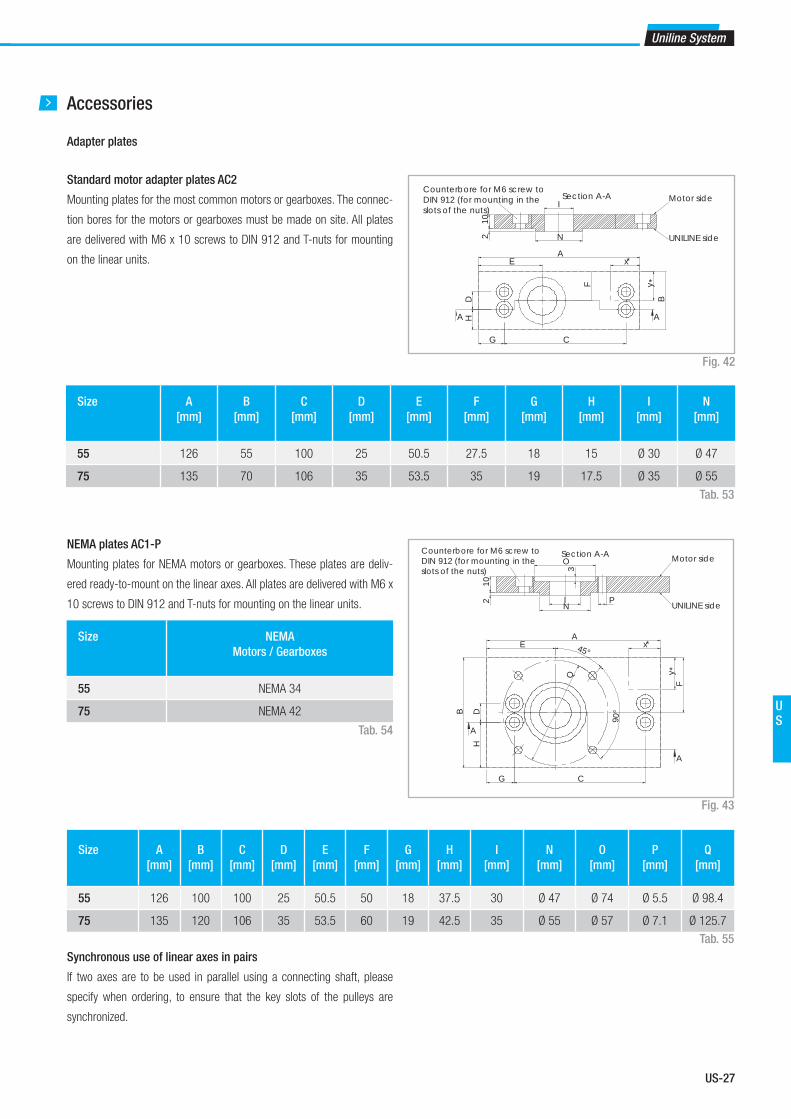
US-27
Uniline System
US
Accessories
Adapter plates
Standard motor adapter plates AC2
Mounting plates for the most common motors or gearboxes. The connec-
tion bores for the motors or gearboxes must be made on site. All plates
are delivered with M6 x 10 screws to DIN 912 and T-nuts for mounting
on the linear units.
Size A
[mm]
B
[mm]
C
[mm]
D
[mm]
E
[mm]
F
[mm]
G
[mm]
H
[mm]
I
[mm]
N
[mm]
55 126 55 100 25 50.5 27.5 18 15 Ø 30 Ø 47
75 135 70 106 35 53.5 35 19 17.5 Ø 35 Ø 55
Fig. 42
Tab. 53
HD
G C
EA
F
B
x
y
A A
*
*
210
N
ISection A-A Motor side
UNILINE side
Counterbore for M6 screw to DIN 912 (for mounting in the slots of the nuts)
NEMA plates AC1-P
Mounting plates for NEMA motors or gearboxes. These plates are deliv-
ered ready-to-mount on the linear axes. All plates are delivered with M6 x
10 screws to DIN 912 and T-nuts for mounting on the linear units.
Fig. 43
Size A
[mm]
B
[mm]
C
[mm]
D
[mm]
E
[mm]
F
[mm]
G
[mm]
H
[mm]
I
[mm]
N
[mm]
O
[mm]
P
[mm]
Q
[mm]
55 126 100 100 25 50.5 50 18 37.5 30 Ø 47 Ø 74 Ø 5.5 Ø 98.4
75 135 120 106 35 53.5 60 19 42.5 35 Ø 55 Ø 57 Ø 7.1 Ø 125.7
Tab. 55
Size NEMA
Motors / Gearboxes
55 NEMA 34
75 NEMA 42
Tab. 54
HDB
A
G C
E
F
45°
90°
Q
x
y
A
A
*
*
A
102 I
N
3O
P
Section A-A Motor side
UNILINE side
Counterbore for M6 screw to DIN 912 (for mounting in the slots of the nuts)
Synchronous use of linear axes in pairs
If two axes are to be used in parallel using a connecting shaft, please
specify when ordering, to ensure that the key slots of the pulleys are
synchronized.

US-28
Fixing brackets APF-2
Fixing clamp for simple mounting of a linear axis on a mounting surface
or for connecting two units with or without a connection plate (see pg.
US-68).
A spacer* may be necessary.
*(Any spacer that may be necessary must be manufactured on site)
Fig. 44
7,51530
6,52 holes 4,5
Section A-A5
4
208,
5
35
7,3
40
20
A
A
T-nut
The maximum tightening torque is 10 Nm.
Fig. 45
Sizes 40 - 75
16,5M6
7,9
A A
1,5
6
Section A-A
T-connection plate APC-1
T-connection plate allows two units to be mounted perpendicu-
lar to each other (see pg. US-65). The plate will not interfere with
the strokes of either unit. All plates are delivered with M6 x 10
screws to DIN 912 and T-nuts for mounting on the linear units.
Fig. 46
Size Fixing holes
for the slider
Fixing holes
for the profi le
55 Holes 2 Holes 5
75 Holes 3 Holes 6
Tab. 56
55 55165
150
11 1
1
2
2
2
2
3
3 3
3
4
4
5
5 5
56
6 6
6
Aluminum profile mounting side
Counterbore for M6 screw to DIN 912 (for mounting in the slots of the nuts)
Slider mounting side
Assembly kits
2 Uniline C series

US-29
Uniline System
US
Size Fixing holes
for the slider
Fixing holes
for the profi le
55 Holes 2 Holes 5
75 Holes 3 Holes 6
Tab. 57
Fig. 47
Angle connection plate APC-2
allows the right angle mounting of two units. The trolley of one unit can
be mounted to the side of the other (see pg. US-66). The plate will not
interfere with the strokes of either unit. All plates are delivered with M6 x
10 screws to DIN 912 and T-nuts for mounting to the linear units.
75
165
8
1
1 1
1 2
2
2
2
3
3
3
3
Aluminum profile mounting side
873 4
5566
Slider mounting side
Counterbore for M6 screw to DIN 912 (for mounting in the slots of the nuts)
X connection plate APC-3
X connection plate for mounting two sliders perpendicular to each other
(see pg. US-67). The plate will not interfere with the strokes of either unit.
All plates are delivered with M6 x 10 screws to DIN 912 and T-nuts for
mounting on the linear units.
Fig. 48
Size Fixing holes
for slider 1
Fixing holes
for slider 2
55 Holes 2 Holes 5
75 Holes 3 Holes 6
Tab. 58
52,5 55160
52,5
55160 1 1
1 1
2 2
2 23
3 3
3
4 4
4 4
55
556 6
66
10
Counterbore for M6 screw to DIN 912(for mounting in the slots of the nuts)

US-30
Identifi cation code for Uniline linear unit
Ordering example: UC 07 1A 1190 1A D 500 L 350
Ordering key
In order to create identifi cation codes for Actuator Line, you can visit: http://confi gureactuator.rollon.com
Ordering key
U C 07
05=55
07=75
1A 1190 1A D 500 L 350
Indices of long slider plate
see from pg. US-22 to pg. US-24
Indices of double slider plate, distance of the centers of slider plates see from pg. US-22 to pg. US-24
Profi le/Rail code
L= Total length of the unit
Driving head code
Size see from pg. US-22 to pg. US-24
Type
Uniline prefi x

US-31
Uniline System
US
Accessories
Standard motor adapter plate
C 07
05=55
07=75
AC2
Standard motor adapter plates see pg. US-27
Size see pg. US-27
Type
Ordering example: C07-AC2
NEMA motor adapter plates
C 07
05=55
07=75
AC1
NEMA motor adapter plates see pg. US-27
Size see pg. US-27
Type
Ordering example: C07-AC1
T-connection plate Order code: APC-1, s. pg. US-28
Angle connection plate Order code: APC-2, s. pg. US-29
X connection plate Order code: APC-3, s. pg. US-29
Fixing clamp Order code: APF-2, s. pg. US-28
Size
Head
codeHole [Ø] 55 75
Metric [mm]with slot for key
12G8 / 4js9 14G8 / 5js9 1A
10G8 / 3js9 16G8 / 5js9 2A
14G8 / 5js9 19G8 / 6js9 3A
16G8 / 5js9 4A
Metric [mm]for compression
coupling
18 1B
24 2B
Inch [in]with slot for key
1⁄2 / 1⁄8 5⁄8 / 3⁄16 1P
3⁄8 / 1⁄8 2P
5⁄8 / 3⁄16 3P
The highlighted connection bores are standard connections
Metric: key seat for keys to DIN 6885 form A
Inch: key seat for keys to BS 46 Part 1: 1958
Motor connection bores
Tab. 59

US-32
3 Uniline E series
Uniline E series description
Uniline is a family of ready-to-install linear actuators. They consist of in-
ternal Compact Rail roller sliders and steel-reinforced polyurethane belts
in a rigid aluminum profile. Longitudinal seals enclose the system. This
arrangement provides the best protection for the actuator from soiling and
damage. In the E series, the fixed bearing rail (T-rail) is mounted horizon-
tally in the aluminum profile, and the compensating bearing rail (U-rail) is
flanged to the outside of the profile as moment support. Versions with long
(L) or double (D) sliders in one axis are possible.
The most important characteristics:
■ Compact design
■ Protected internal linear guides
■ High traversing speeds
■ Grease-free operation possible (depending on the application. For
further information, please contact our Application Engineering
department)
■ High versatility
■ Long strokes
■ Versions with long or multiple sliders available in one linear axis
Preferred areas of application:
■ Handling and automation
■ Multi-axis gantries
■ Packaging machines
■ Cutting machines
■ Displaceable panels
■ Painting installations
■ Welding robots
■ Special machines
Technical data:
■ Available sizes [mm]:
Type E: 55, 75
■ Length and stroke tolerances:
For strokes <1 m: +0 mm to +10 mm (+0 in to 0.4 in)
For strokes >1 m: +0 mm to +15 mm (+0 in to 0.59 in)
Fig. 49
Uniline E series

US-33
Uniline System
US
The components
Extruded profi le
The anodized 6060 aluminum alloy extrusion used for the profi le of the
Rollon Uniline E series linear units were designed and manufactured by in-
dustry experts to optimize weight while maintaining mechanical strength.
(see physical-chemical characteristics below).The dimensional tolerances
comply with EN 755-9 standard.
Driving belt
The Rollon Uniline E series linear units use steel reinforced polyurethane
drive belts with RPP pitch and parabolic profi les. This belt is ideal due to its
high load transmission characteristics, compact size and low noise. Used
in conjunction with a backlash-free pulley, smooth alternating motion can
General data about aluminum used: AL 6060
Chemical composition [%]
Physical characteristics
Mechanical characteristics
be achieved. Optimization of the maximum belt width/body dimension
ratio enables the following performance characteristics to be achieved:
■ High speed
■ Low noise
■ Low wear
Carriage
The carriage of the Rollon Uniline E series linear units are made entirely
of anodized aluminum. Each carriage has mounting T-slots for the con-
nection to the moving element. Rollon offers multiple carriages to accom-
modate a vast array of applications.
AI Mg Si Fe Mn Zn Cu Impurites
Remainder 0.35-0.60 0.30-0.60 0.30 0.10 0.10 0.10 0.05-0.15
Density Coeff. of
elasticity
Coeff. of thermal expansion
(20°-100°C)
Thermal conductivity
(20°C)
Specifi c heat
(0°-100°C)
Resistivity Melting point
kg___
dm3
kN___
mm2
10-6
___
K
W_____
m . K
J_____
kg . K
Ω . m . 10-9 °C
2.7 69 23 200 880-900 33 600-655
Rm Rp (02) A HB
N___
mm2
N___
mm2
% __
205 165 10 60-80
Tab. 60
Tab. 61
Tab. 62

US-34
ZL
Slider S Stroke** Z
A
AB
J KY X
HD
2,2
8,216
,5
9
F
C GE
A
A
Bore diameter *
IN
M MA
A
V W V
F
Section A-A
Z Slider S Slider S Stroke* ZL
Ln
E55 system
E55
Fig. 50
Tab. 63* For the position of the T-nuts when using our motor adapter plates, see pg. US-39ff
** Maximum stroke for a single-piece guiding rail. For longer strokes, see tab. 68
E55L with long slider
Fig. 51
Fig. 52
Type Smin
[mm]
Smax
[mm]
Sn
[mm]
Z
[mm]
Stroke*
[mm]
E55L 310 500 Sn = Smin
+ n ·10 108 2770
Tab. 64* Maximum stroke for a single-piece guiding rail and a maximum slider plate length Smax
For longer strokes, see tab. 68
E55D with double slider
Type S
[mm]
Lmin
[mm]
Lmax
**
[mm]
Ln
[mm]
Z
[mm]
Stroke*
[mm]
E55D 200 300 3070 Ln = Lmin
+ n · 5 108 2770
Tab. 65* Maximum stroke for a single-piece guiding rail and a minimum slider plate distance Lmin
** Maximum distance Lmax
between the centres of slider plates at a stroke of 0 mm
For longer strokes, see tab. 68
Type A
[mm]
B
[mm]
C*
[mm]
D
[mm]
E
[mm]
F
[mm]
G*
[mm]
H
[mm]
I
[mm]
J
[mm]
K
[mm]
M
[mm]
N
[mm]
S
[mm]
X
[mm]
Y
[mm]
V
[mm]
W
[mm]
Z
[mm]
Stroke**
[mm]
E55 55 71 67.5 25 50.5 27.5 32.5 15 Ø 24.9 1.5 71 2.35 Ø 47 200 28 12 0.5 54 108 3070
ZL
Slider Sn Stroke* Z
3 Uniline E series
* For information on the motor connection bores, see ordering key. ** The length of the safety stroke is provided on request according to the customer's specifi c requirements.
* The length of the safety stroke is provided on request according to the customer's specifi c requirements.
* The length of the safety stroke is provided on request according to the customer's specifi c requirements.

US-35
Uniline System
US
Load ratings, moments and characteristic data
Type C
[N]
C0rad
[N]
C0ax
[N]
Mx
[Nm]
My
[Nm]
Mz
[Nm]
E55 4260 2175 1500 25.5 43.4 54.4
E55-L 8520 4350 3000 51 165 to 450 239 to 652
E55-D 8520 4350 3000 51 450 to 4605 652 to 6677
Tab. 67For the calculation of the allowed moments, please observe pages SL-5ff
Technical dataType
E55
Standard belt tension [N] 220
Moment at no load [Nm] 0.3
Max. traversing speed [m/s] 3
Max. acceleration [m/s²] 10
Repeat accuracy [mm] 0.1
Linear accuracy [mm] 0.8
Compact Rail guiding rail TLV28 / ULV18
Slider type CS28 spec. / CPA 18
Moment of inertia Iy [cm4] 34.6
Moment of inertia Iz [cm4] 41.7
Pitch diameter of pulley [m] 0.04138
Moment of inertia of each pulley [gmm²] 45633
Stroke per shaft revolution [mm] 130
Mass of slider [g] 635
Weight with zero stroke [g] 3167
Weight with 1 m stroke [g] 5055
Max. stroke [mm] 5500
Working temperature from -20 °C to + 80 °C
Tab. 68
E55
Fig. 53
C0ax
My
Mz
Mx
C0rad
Tab. 66
Type Type of belt Belt width
[mm]
Weight
kg/m
E55 18RPP5 18 0.074
Driving belt
The driving belt is manufactured from a friction resistant polyurethane and
with steel cords for high tensile stress resistance.
Belt length (mm) = 2 x L - 182 Standard slider
Belt length (mm) = 2 x L - Sn+18 Long slider
Belt length (mm) = 2 x L - Ln - 182 Double slider

US-36
E75 system
E75
Fig. 54
Tab. 69* For the position of the T-nuts when using our motor adapter plates, see pg. US-39ff
** Maximum stroke for a single-piece guiding rail. For longer strokes, see tab. 74
Type A
[mm]
B
[mm]
C*
[mm]
D
[mm]
E
[mm]
F
[mm]
G*
[mm]
H
[mm]
I
[mm]
J
[mm]
K
[mm]
M
[mm]
N
[mm]
S
[mm]
X
[mm]
Y
[mm]
V
[mm]
W
[mm]
Z
[mm]
Stroke**
[mm]
E75 75 90 71.5 35 53.5 38.8 34.5 20 Ø 29.5 5 95 4.85 Ø 55 285 36 14.5 2.3 70.4 116 3420
3 Uniline E series
ZL
Slider S Stroke** Z
A
AB
J KY X
HD
2,2
8,216
,5
9
F
C GE
A
A
Bore diameter *
IN
M MA
A
V W V
F
Section A-A
Z Slider S Slider S Stroke* ZL
Ln
E75L with long slider
Fig. 55
Fig. 56
Type Smin
[mm]
Smax
[mm]
Sn
[mm]
Z
[mm]
Stroke*
[mm]
E75L 440 700 Sn = Smin
+ n ·10 116 3000
Tab. 70* Maximum stroke for a single-piece guiding rail and a maximum slider plate length Smax
For longer strokes, see tab. 74
E75D with double slider
Type S
[mm]
Lmin
[mm]
Lmax
**
[mm]
Ln
[mm]
Z
[mm]
Stroke*
[mm]
E75D 285 416 3416 Ln = Lmin
+ n · 8 116 3000
Tab. 71* Maximum stroke for a single-piece guiding rail and a minimum slider plate distance Lmin
** Maximum distance Lmax
between the centres of slider plates at a stroke of 0 mm
For longer strokes, see tab. 74
ZL
Slider Sn Stroke* Z
* For information on the motor connection bores, see ordering key. ** The length of the safety stroke is provided on request according to the customer's specifi c requirements.
* The length of the safety stroke is provided on request according to the customer's specifi c requirements.
* The length of the safety stroke is provided on request according to the customer's specifi c requirements.

US-37
Uniline System
US
Load ratings, moments and characteristic data
Type C
[N]
C0rad
[N]
C0ax
[N]
Mx
[Nm]
My
[Nm]
Mz
[Nm]
E75 12280 5500 3710 85.5 163 209
E75-L 24560 11000 7420 171 575 to 1540 852 to 2282
E75-D 24560 11000 7420 171 1543 to 12673 2288 to 18788
Tab. 73For the calculation of the allowed moments, please see pages SL-5ff
Technical dataType
E75
Standard belt tension [N] 800
Moment at no load [Nm] 1.3
Max. traversing speed [m/s] 5
Max. acceleration [m/s²] 15
Repeat accuracy [mm] 0.1
Linear accuracy [mm] 0.8
Compact Rail guiding rail TLV43 / ULV28
Slider type CS43 spec. / CPA 28
Moment of inertia Iy [cm4] 127
Moment of inertia Iz [cm4] 172
Pitch diameter of pulley [m] 0.05093
Moment of inertia of each pulley [gmm²] 139969
Stroke per shaft revolution [mm] 160
Mass of slider [g] 1772
Weight with zero stroke [g] 7544
Weight with 1 m stroke [g] 10751
Max. stroke [mm] 7500
Working temperature from -20 °C to + 80 °C
Tab. 74
E75
Fig. 57
C0ax
My
Mz
Mx
C0rad
Tab. 72
Type Type of belt Belt width
[mm]
Weight
kg/m
E75 30RPP8 30 0.185
Driving belt
The driving belt is manufactured from a friction resistant polyurethane and
with steel cords for high tensile stress resistance.
Belt length (mm) = 2 x L - 213 Standard slider
Belt length (mm) = 2 x L - Sn+72 Long slider
Belt length (mm) = 2 x L - Ln - 213 Double slider

US-38
Lubrication
The raceways of the guide rails in the Uniline linear axes are prelubricated.
To achieve the calculated service life, a lubrication film must always be
present between the raceway and the roller. The lubrication film also pro-
vides anticorrosion protection to the ground raceways. An approximate
value for the lubrication period is every 100 km or every six months. The
recommended lubricant is a lithium-based roller bearing grease of me-
dium consistency.
Lubrication of the raceways
Proper lubrication under normal conditions:
■ reduces friction
■ reduces wear
■ reduces stress on the contact faces
■ reduces running noise
Tab. 75
Lubricants Thickeners Temperature range
[°C]
Dynamic viscosity [mPas]
Roller bearing grease Lithium soap -30 to +170 <4500
Relubrication of the guide rails
These types of rails have a lubricating conduit on the side of the slider
plate through which the lubricant can be applied directly to the raceways.
Lubrication can be done in one of two ways:
1. Relubrication using a grease gun:
This is done by inserting the tip of the grease gun into the conduit at the
slider plate and injecting the grease inside (see fig. 58). Please note that
the grease has to fill the whole conduit in order to lubricate the rail prop-
erly; for this reason sufficient grease must be used.
2. Automatic lubrication system:
To connect the unit to an automatic greasing system, use a proper adapt-
er/connector* that attaches to the threaded hole on the side of the trolley. Fig. 58
Fig. 59
AA BB
CC
The advantage of this solution is the possibility of rail re-lubrication with-
out machine downtime.
*(Any adapter that may be necessary must be manufactured on site)
Cleaning the guide rails
It is always recommended to clean the slider rail prior to any relubrication,
in order to remove grease residues. This can be done while performing
maintenance work or during a scheduled machine stop.
1. Unscrew the safety screws C (on top of the slider plate) from the belt
tensioning device A (see fig. 59).
2. Also completely unscrew the belt tensioning screws B and remove the
belt tensioning devices A from their housings.
3. Lift the toothed belt until the guide rails can be seen.
Important: Ensure that the side seal is not damaged.
4. Clean the rail raceways with a clean and dry cloth. Ensure that all
grease and dirt residues from previous work processes are removed.
To ensure that the rails are cleaned over their entire length, the slider
plate should be moved once over its entire length.
5. Apply a sufficient amount of grease to the raceways.
3 Uniline E series
6. Re-insert the belt tensioning devices A into their housings and mount
the belt tensioning screws B. Re-adjust the belt tension (see pg. US-63).
7. Fasten the safety screws C.

US-39
Uniline System
US
Accessories
Adapter plates
Standard motor adapter plates AC2
Mounting plates for the most common motors or gearboxes. The connec-
tion bores for the motors or gearboxes must be made on site. All plates
are delivered with M6 x 10 screws to DIN 912 and T-nuts for mounting
on the linear units.
Size A
[mm]
B
[mm]
C
[mm]
D
[mm]
E
[mm]
F
[mm]
G
[mm]
H
[mm]
I
[mm]
N
[mm]
55 126 55 100 25 50.5 27.5 18 15 Ø 30 Ø 47
75 135 70 106 35 53.5 35 19 17.5 Ø 35 Ø 55
Fig. 60
Tab. 76
HD
G C
EA
F
B
x
y
A A
*
*
210
N
ISection A-A Motor side
UNILINE side
Counterbore for M6 screw to DIN 912 (for mounting in the slots of the nuts)
NEMA plates AC1-P
Mounting plates for NEMA motors or gearboxes. These plates are deliv-
ered ready-to-mount on the linear axes. All plates are delivered with M6 x
10 screws to DIN 912 and T-nuts for mounting on the linear units.
Fig. 61
Size A
[mm]
B
[mm]
C
[mm]
D
[mm]
E
[mm]
F
[mm]
G
[mm]
H
[mm]
I
[mm]
N
[mm]
O
[mm]
P
[mm]
Q
[mm]
55 126 100 100 25 50.5 50 18 37.5 30 Ø 47 Ø 74 Ø 5.5 Ø 98.4
75 135 120 106 35 53.5 60 19 42.5 35 Ø 55 Ø 57 Ø 7.1 Ø 125.7
Tab. 78
Size NEMA
Motors / Gearboxes
55 NEMA 34
75 NEMA 42
Tab. 77
HDB
A
G C
E
F
45°
90°
Q
x
y
A
A
*
*
102 I
N
3O
P
Section A-A Motor side
UNILINE side
Counterbore for M6 screw to DIN 912 (for mounting in the slots of the nuts)
Synchronous use of linear axes in pairs
If two axes are to be used in parallel using a connecting shaft, please
specify when ordering, to ensure that the key slots of the pulleys are
synchronized.

US-40
3 Uniline E series
Fixing brackets APF-2
Fixing clamp for simple mounting of a linear axis on a mounting surface
or for connecting two units with or without a connection plate (see pg.
US-68).
A spacer* may be necessary.
*(Any spacer that may be necessary must be manufactured on site)
Fig. 62
7,51530
6,52 holes 4,5
Section A-A5
4
208,
5
35
7,3
40
20
A
A
T-nut
The maximum tightening torque is 10 Nm.
Fig. 63
Sizes 40 - 75
16,5M6
7,9
A A
1,5
6
Section A-A
T-connection plate APC-1
T-connection plate allows two units to be mounted perpendicu-
lar to each other (see pg. US-65). The plate will not interfere with
the strokes of either unit. All plates are delivered with M6 x 10
screws to DIN 912 and T-nuts for mounting on the linear units.
Fig. 64
Size Fixing holes
for the slider
Fixing holes
for the profi le
55 Holes 2 Holes 5
75 Holes 3 Holes 6
Tab. 79
Note
This adapter plate can be used with types E and ED only to a limited
extent. For further information, please contact our Application Engineering
Department.
55 55165
150
11 1
1
2
2
2
2
3
3 3
3
4
4
5
5 5
56
6 6
6
Aluminum profile mounting side
Counterbore for M6 screw to DIN 912 (for mounting in the slots of the nuts)
Slider mounting side
Assembly kits

US-41
Uniline System
US
Size Fixing holes
for the slider
Fixing holes
for the profi le
55 Holes 2 Holes 5
75 Holes 3 Holes 6
Tab. 80
Fig. 65
Angle connection plate APC-2
allows the right angle mounting of two units. The trolley of one unit can
be mounted to the side of the other (see pg. US-66). The plate will not
interfere with the strokes of either unit. All plates are delivered with M6 x
10 screws to DIN 912 and T-nuts for mounting to the linear units.
Note
This adapter plate can be used with types E and ED only to a limited
extent. For further information, please contact our Application Engineering
Department.75
165
8
1
1 1
1 2
2
2
2
3
3
3
3
Aluminum profile mounting side
873 4
5566
Slider mounting side
Counterbore for M6 screw to DIN 912 (for mounting in the slots of the nuts)
X connection plate APC-3
X connection plate for mounting two sliders perpendicular to each other
(see pg. US-67). The plate will not interfere with the strokes of either unit.
All plates are delivered with M6 x 10 screws to DIN 912 and T-nuts for
mounting on the linear units.
Fig. 66
Size Fixing holes
for slider 1
Fixing holes
for slider 2
55 Holes 2 Holes 5
75 Holes 3 Holes 6
Tab. 8152,5 55
160
52,5
55160 1 1
1 1
2 2
2 23
3 3
3
4 4
4 4
55
556 6
66
10
Counterbore for M6 screw to DIN 912(for mounting in the slots of the nuts)

US-42
Identifi cation code for Uniline linear unit
Ordering example: UE 07 1A 1190 1A D 500 L 350
Ordering key
In order to create identifi cation codes for Actuator Line, you can visit: http://confi gureactuator.rollon.com
U E 07
05=55
07=75
1A 1190 1A D 500 L 350
Indices of long slider plate
see from pg. US-34 to pg. US-36
Indices of double slider plate, distance of the centers of slider plates see from pg. US-34 to pg. US-36
Profi le/Rail code
L= Total length of the unit
Driving head code
Size see from pg. US-34 to pg. US-36
Type
Uniline prefi x
Ordering key
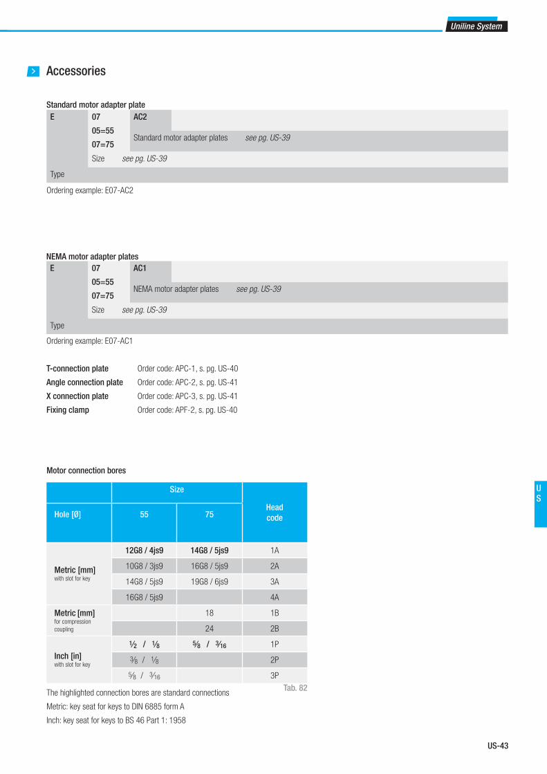
US-43
Uniline System
US
Accessories
Standard motor adapter plate
E 07
05=55
07=75
AC2
Standard motor adapter plates see pg. US-39
Size see pg. US-39
Type
Ordering example: E07-AC2
NEMA motor adapter plates
E 07
05=55
07=75
AC1
NEMA motor adapter plates see pg. US-39
Size see pg. US-39
Type
Ordering example: E07-AC1
T-connection plate Order code: APC-1, s. pg. US-40
Angle connection plate Order code: APC-2, s. pg. US-41
X connection plate Order code: APC-3, s. pg. US-41
Fixing clamp Order code: APF-2, s. pg. US-40
Size
Head
codeHole [Ø] 55 75
Metric [mm]with slot for key
12G8 / 4js9 14G8 / 5js9 1A
10G8 / 3js9 16G8 / 5js9 2A
14G8 / 5js9 19G8 / 6js9 3A
16G8 / 5js9 4A
Metric [mm]for compression
coupling
18 1B
24 2B
Inch [in]with slot for key
1⁄2 / 1⁄8 5⁄8 / 3⁄16 1P
3⁄8 / 1⁄8 2P
5⁄8 / 3⁄16 3P
The highlighted connection bores are standard connections
Metric: key seat for keys to DIN 6885 form A
Inch: key seat for keys to BS 46 Part 1: 1958
Motor connection bores
Tab. 82

US-44
4 Uniline ED series
Uniline ED series description
Uniline is a family of ready-to-install linear actuators. They consist of in-
ternal Compact Rail roller sliders and steel-reinforced polyurethane belts
in a rigid aluminum profile. Longitudinal seals enclose the system. This
arrangement provides the best protection for the actuator from soiling and
damage. In the ED series, a compensating bearing rail (U-rail) is mounted
horizontally in the aluminum profile, and for increased moment support,
two more compensating bearing rails (U-rail) are flanged to the profile
externally. Versions with long (L) or double (D) sliders in one axis are pos-
sible.
The most important characteristics:
■ Compact design
■ Protected internal linear guides
■ High traversing speeds
■ Grease-free operation possible (depending on the application. For
further information, please contact our Application Engineering
department)
■ High versatility
■ Long strokes
■ Versions with long or multiple sliders available in one linear axis
Preferred areas of application:
■ Handling and automation
■ Multi-axis gantries
■ Packaging machines
■ Cutting machines
■ Displaceable panels
■ Painting installations
■ Welding robots
■ Special machines
Technical data:
■ Available sizes [mm]:
Type ED: 75
■ Length and stroke tolerances:
For strokes <1 m: +0 mm to +10 mm (+0 in to 0.4 in)
For strokes >1 m: +0 mm to +15 mm (+0 in to 0.59 in)
Fig. 67
Uniline ED series

US-45
Uniline System
US
The components
Extruded profi le
The anodized 6060 aluminum alloy extrusion used for the profi le of the
Rollon Uniline ED series linear units were designed and manufactured
by industry experts to optimize weight while maintaining mechanical
strength. (see physical-chemical characteristics below).The dimensional
tolerances comply with EN 755-9 standard.
Driving belt
The Rollon Uniline ED series linear units use steel reinforced polyurethane
drive belts with RPP pitch and parabolic profi les. This belt is ideal due to its
high load transmission characteristics, compact size and low noise. Used
in conjunction with a backlash-free pulley, smooth alternating motion can
General data about aluminum used: AL 6060
Chemical composition [%]
Physical characteristics
Mechanical characteristics
be achieved. Optimization of the maximum belt width/body dimension
ratio enables the following performance characteristics to be achieved:
■ High speed
■ Low noise
■ Low wear
Carriage
The carriage of the Rollon Uniline ED series linear units are made entirely
of anodized aluminum. Each carriage has mounting T-slots for the con-
nection to the moving element. Rollon offers multiple carriages to accom-
modate a vast array of applications.
AI Mg Si Fe Mn Zn Cu Impurites
Remainder 0.35-0.60 0.30-0.60 0.30 0.10 0.10 0.10 0.05-0.15
Density Coeff. of
elasticity
Coeff. of thermal expansion
(20°-100°C)
Thermal conductivity
(20°C)
Specifi c heat
(0°-100°C)
Resistivity Melting point
kg___
dm3
kN___
mm2
10-6
___
K
W_____
m . K
J_____
kg . K
Ω . m . 10-9 °C
2.7 69 23 200 880-900 33 600-655
Rm Rp (02) A HB
N___
mm2
N___
mm2
% __
205 165 10 60-80
Tab. 83
Tab. 84
Tab. 85

US-46
Z Slider S Stroke** ZL
A
A B
K
HD
YX
8,2
9
2,2
16,5
F
C GE
A
A
Bore diameter *
IN
M MA
A
V W V
F
Section A-A
ZL
Slider S Stroke* Z
ED75 system
ED75
Fig. 68
Tab. 86* For the position of the T-nuts when using our motor adapter plates, see pg. US-49ff
** Maximum stroke for a single-piece guiding rail. For longer strokes, see tab. 91
ED75L with long slider
Fig. 69
Fig. 70
Type Smin
*
[mm]
Smax
[mm]
Sn
[mm]
Z
[mm]
Stroke**
[mm]
ED75L 440 700 Sn = Smin
+ n · 10 116 2500
Tab. 87* The length of 440 mm is considered standard, all other lengths are considered special dimensions
** Maximum stroke for a single-piece guiding rail and a maximum slider plate length Smax
For longer strokes, see tab. 91
ED75D with double slider
Type S
[mm]
Lmin
[mm]
Lmax
**
[mm]
Ln
[mm]
Z
[mm]
Stroke*
[mm]
ED75D 330 416 2864 Ln = Lmin
+ n · 8 116 2450
Tab. 88* Maximum stroke for a single-piece guiding rail and a minimum slider plate distance Lmin
** Maximum distance Lmax
between the centres of slider plates at a stroke of 0 mm
For longer strokes, see tab. 91
Type A
[mm]
B
[mm]
C*
[mm]
D
[mm]
E
[mm]
F
[mm]
G*
[mm]
H
[mm]
I
[mm]
K
[mm]
M
[mm]
N
[mm]
S
[mm]
X
[mm]
Y
[mm]
V
[mm]
W
[mm]
Z
[mm]
Stroke**
[mm]
ED75 75 90 71.5 35 53.5 38.8 34.5 20 Ø 29.5 135 4.85 Ø 55 330 36 49.5 2.3 70.4 116 2900
Z Slider S Slider S Stroke* ZL
Ln
4 Uniline ED series
* For information on the motor connection bores, see ordering key. ** The length of the safety stroke is provided on request according to the customer's specifi c requirements.
* The length of the safety stroke is provided on request according to the customer's specifi c requirements.
* The length of the safety stroke is provided on request according to the customer's specifi c requirements.

US-47
Uniline System
US
Type ED
Fig. 71
Type C
[N]
C0rad
[N]
C0ax
[N]
Mx
[Nm]
My
[Nm]
Mz
[Nm]
ED75 9815 5500 8700 400.2 868 209
ED75-L 19630 11000 8700 400.2 1174 to 2305 852 to 2282
ED75-D 19630 11000 17400 800.4 3619 to 24917 2288 to 15752
Tab. 90For the calculation of the allowed moments, please see pages SL-5ff
Tab. 91
Technical dataType
ED75
Standard belt tension [N] 1000
Moment at no load [Nm] 1.5
Max. traversing speed [m/s] 5
Max. acceleration [m/s²] 15
Repeat accuracy [mm] 0.1
Linear accuracy [mm] 0.8
Compact Rail guiding rail ULV43 / ULV28
Slider type CS43 spec. / CS28 spec.
Moment of inertia Iy [cm4] 127
Moment of inertia Iz [cm4] 172
Pitch diameter of pulley [m] 0.05093
Moment of inertia of each pulley [gmm²] 139969
Stroke per shaft revolution [mm] 160
Mass of slider [g] 3770
Weight with zero stroke [g] 9850
Weight with 1 m stroke [g] 14400
Max. stroke [mm] 7500
Working temperature from -20 °C to + 80 °C
C0ax
My
Mz
Mx
C0rad
Tab. 89
Type Type of belt Belt width
[mm]
Weight
kg/m
ED75 30RPP8 30 0.185
Driving belt
The driving belt is manufactured from a friction resistant polyurethane and
with steel cords for high tensile stress resistance.
Belt length (mm) = 2 x L - 258 Standard slider
Belt length (mm) = 2 x L - Sn+72 Long slider
Belt length (mm) = 2 x L - Ln - 258 Double slider
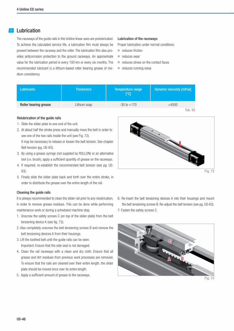
US-48
Lubrication
The raceways of the guide rails in the Uniline linear axes are prelubricated.
To achieve the calculated service life, a lubrication film must always be
present between the raceway and the roller. The lubrication film also pro-
vides anticorrosion protection to the ground raceways. An approximate
value for the lubrication period is every 100 km or every six months. The
recommended lubricant is a lithium-based roller bearing grease of me-
dium consistency.
Lubrication of the raceways
Proper lubrication under normal conditions:
■ reduces friction
■ reduces wear
■ reduces stress on the contact faces
■ reduces running noise
Tab. 92
Lubricants Thickeners Temperature range
[°C]
Dynamic viscosity [mPas]
Roller bearing grease Lithium soap -30 to +170 <4500
Fig. 73
AA BB
CC
Cleaning the guide rails
It is always recommended to clean the slider rail prior to any relubrication,
in order to remove grease residues. This can be done while performing
maintenance work or during a scheduled machine stop.
1. Unscrew the safety screws C (on top of the slider plate) from the belt
tensioning device A (see fig. 73).
2. Also completely unscrew the belt tensioning screws B and remove the
belt tensioning devices A from their housings.
3. Lift the toothed belt until the guide rails can be seen.
Important: Ensure that the side seal is not damaged.
4. Clean the rail raceways with a clean and dry cloth. Ensure that all
grease and dirt residues from previous work processes are removed.
To ensure that the rails are cleaned over their entire length, the slider
plate should be moved once over its entire length.
5. Apply a sufficient amount of grease to the raceways.
Relubrication of the guide rails
1. Slide the slider plate to one end of the unit.
2. At about half the stroke press and manually move the belt in order to
see one of the two rails inside the unit (see Fig. 72).
It may be necessary to release or loosen the belt tension. See chapter
Belt tension (pg. US-63).
3. By using a grease syringe (not supplied by ROLLON) or an alternative
tool (i.e. brush), apply a sufficient quantity of grease on the raceways.
4. If required, re-establish the recommended belt tension (see pg. US-
63).
5. Finally slide the slider plate back and forth over the entire stroke, in
order to distribute the grease over the entire length of the rail.
Fig. 72
4 Uniline ED series
6. Re-insert the belt tensioning devices A into their housings and mount
the belt tensioning screws B. Re-adjust the belt tension (see pg. US-63).
7. Fasten the safety screws C.

US-49
Uniline System
US
Accessories
Adapter plates
Standard motor adapter plates AC2
Mounting plates for the most common motors or gearboxes. The connec-
tion bores for the motors or gearboxes must be made on site. All plates
are delivered with M6 x 10 screws to DIN 912 and T-nuts for mounting
on the linear units.
Size A
[mm]
B
[mm]
C
[mm]
D
[mm]
E
[mm]
F
[mm]
G
[mm]
H
[mm]
I
[mm]
N
[mm]
75 135 70 106 35 53.5 35 19 17.5 Ø 35 Ø 55
Fig. 74
Tab. 93H
D
G C
EA
F
B
x
y
A A
*
*
210
N
ISection A-A Motor side
UNILINE side
Counterbore for M6 screw to DIN 912 (for mounting in the slots of the nuts)
* Area of plate needs to be cut if used for ED75 linear unit. (Adding 20 mm to total length of unit will
render this modification unnecessary). Othewise it gets in contact with the outer rail.
X = 20 mm; Y = 35 mm
NEMA plates AC1-P
Mounting plates for NEMA motors or gearboxes. These plates are deliv-
ered ready-to-mount on the linear axes. All plates are delivered with M6 x
10 screws to DIN 912 and T-nuts for mounting on the linear units.
Fig. 75
Size A
[mm]
B
[mm]
C
[mm]
D
[mm]
E
[mm]
F
[mm]
G
[mm]
H
[mm]
I
[mm]
N
[mm]
O
[mm]
P
[mm]
Q
[mm]
75 135 120 106 35 53.5 60 19 42.5 35 Ø 55 Ø 57 Ø 7.1 Ø 125.7
Tab. 95
Size NEMA
Motors / Gearboxes
75 NEMA 42
Tab. 94
* Area of plate needs to be cut if used for ED75 linear unit. (Adding 20 mm to total length of unit will
render this modification unnecessary). Othewise it gets in contact with the outer rail.
X = 20 mm; Y = 60 mm
HDB
A
G C
E
F
45°
90°
Q
x
y
A
A
*
*A
102 I
N
3O
P
Section A-A Motor side
UNILINE side
Counterbore for M6 screw to DIN 912 (for mounting in the slots of the nuts)
Synchronous use of linear axes in pairs
If two axes are to be used in parallel using a connecting shaft, please
specify when ordering, to ensure that the key slots of the pulleys are
synchronized.
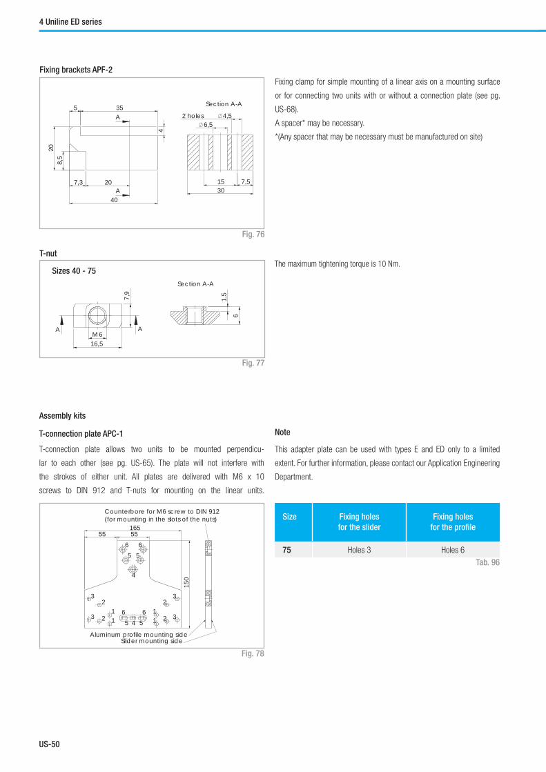
US-50
Fixing brackets APF-2
Fixing clamp for simple mounting of a linear axis on a mounting surface
or for connecting two units with or without a connection plate (see pg.
US-68).
A spacer* may be necessary.
*(Any spacer that may be necessary must be manufactured on site)
Fig. 76
7,51530
6,52 holes 4,5
Section A-A5
4
208,
5
35
7,3
40
20
A
A
T-nut
The maximum tightening torque is 10 Nm.
Fig. 77
Sizes 40 - 75
16,5M6
7,9
A A
1,5
6
Section A-A
T-connection plate APC-1
T-connection plate allows two units to be mounted perpendicu-
lar to each other (see pg. US-65). The plate will not interfere with
the strokes of either unit. All plates are delivered with M6 x 10
screws to DIN 912 and T-nuts for mounting on the linear units.
Fig. 78
Size Fixing holes
for the slider
Fixing holes
for the profi le
75 Holes 3 Holes 6
Tab. 96
Note
This adapter plate can be used with types E and ED only to a limited
extent. For further information, please contact our Application Engineering
Department.
55 55165
150
11 1
1
2
2
2
2
3
3 3
3
4
4
5
5 5
56
6 6
6
Aluminum profile mounting side
Counterbore for M6 screw to DIN 912 (for mounting in the slots of the nuts)
Slider mounting side
Assembly kits
4 Uniline ED series
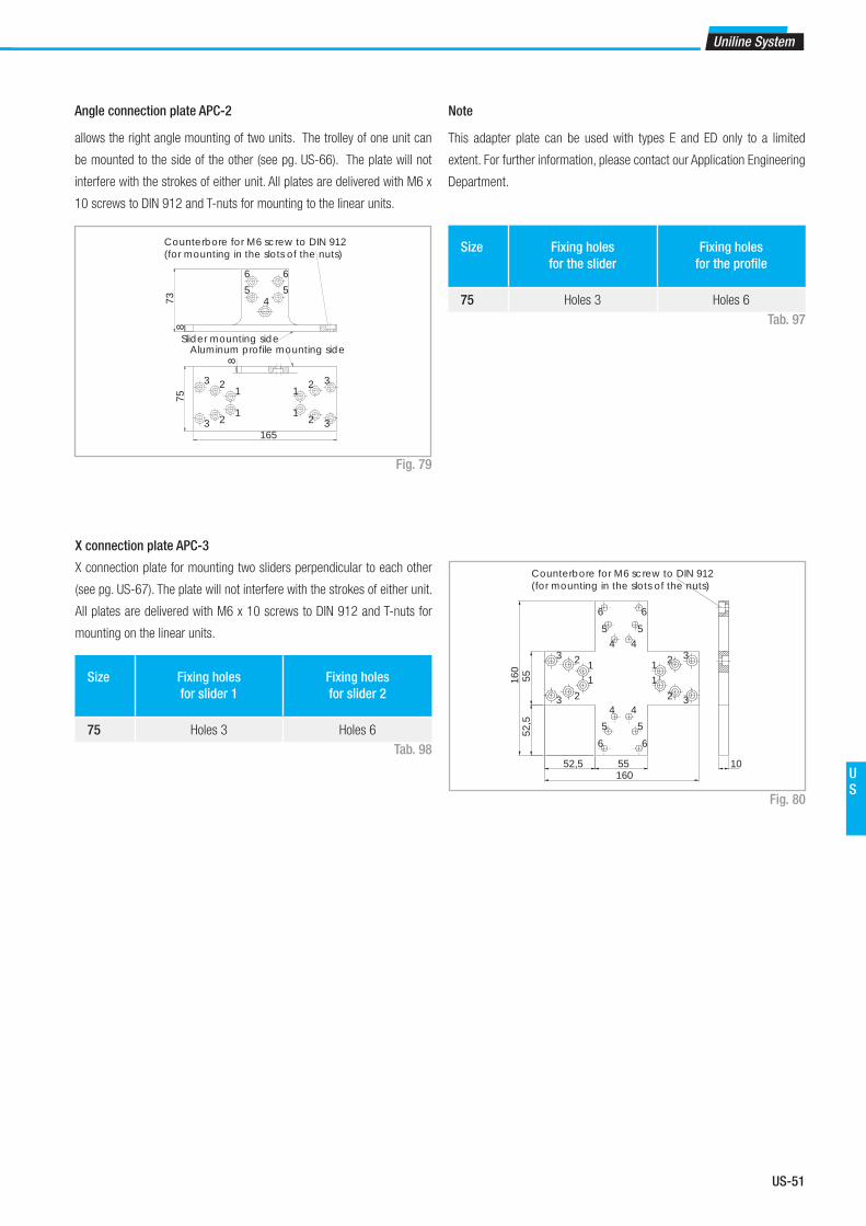
US-51
Uniline System
US
Size Fixing holes
for the slider
Fixing holes
for the profi le
75 Holes 3 Holes 6
Tab. 97
Fig. 79
Angle connection plate APC-2
allows the right angle mounting of two units. The trolley of one unit can
be mounted to the side of the other (see pg. US-66). The plate will not
interfere with the strokes of either unit. All plates are delivered with M6 x
10 screws to DIN 912 and T-nuts for mounting to the linear units.
Note
This adapter plate can be used with types E and ED only to a limited
extent. For further information, please contact our Application Engineering
Department.75
165
8
1
1 1
1 2
2
2
2
3
3
3
3
Aluminum profile mounting side
873 4
5566
Slider mounting side
Counterbore for M6 screw to DIN 912 (for mounting in the slots of the nuts)
X connection plate APC-3
X connection plate for mounting two sliders perpendicular to each other
(see pg. US-67). The plate will not interfere with the strokes of either unit.
All plates are delivered with M6 x 10 screws to DIN 912 and T-nuts for
mounting on the linear units.
Fig. 80
Size Fixing holes
for slider 1
Fixing holes
for slider 2
75 Holes 3 Holes 6
Tab. 9852,5 55
160
52,5
55160 1 1
1 1
2 2
2 23
3 3
3
4 4
4 4
55
556 6
66
10
Counterbore for M6 screw to DIN 912(for mounting in the slots of the nuts)

US-52
Identifi cation code for Uniline linear unit
Ordering example: UD 07 1A 1190 1A D 500 L 350
Ordering key
In order to create identifi cation codes for Actuator Line, you can visit: http://confi gureactuator.rollon.com
U D 07
07=75
1A 1190 1A D 500 L 350
Indices of long slider plate
see pg. US-46
Indices of double slider plate, distance of the centers of slider plates see pg. US-46
Profi le/Rail code
L= Total length of the unit
Driving head code
Size see pg. US-46
Type
Uniline prefi x
Ordering key

US-53
Uniline System
US
Accessories
Standard motor adapter plate
D 07
07=75
AC2
Standard motor adapter plates see pg. US-49
Size see pg. US-49
Type
Ordering example: D07-AC2
NEMA motor adapter plates
D 07
07=75
AC1
NEMA motor adapter plates see pg. US-49
Size see pg. US-49
Type
Ordering example: D07-AC1
T-connection plate Order code: APC-1, s. pg. US-50
Angle connection plate Order code: APC-2, s. pg. US-51
X connection plate Order code: APC-3, s. pg. US-51
Fixing clamp Order code: APF-2, s. pg. US-50
Size
Head
codeHole [Ø] 75
Metric [mm]with slot for key
14G8 / 5js9 1A
16G8 / 5js9 2A
19G8 / 6js9 3A
4A
Metric [mm]for compression
coupling
18 1B
24 2B
Inch [in]with slot for key
5⁄8 / 3⁄16 1P
2P
3P
The highlighted connection bores are standard connections
Metric: key seat for keys to DIN 6885 form A
Inch: key seat for keys to BS 46 Part 1: 1958
Motor connection bores
Tab. 99

US-54
5 Uniline H series
Uniline H series description
Uniline is a family of ready-to-install linear actuators. They consist of in-
ternal Compact Rail roller sliders in a rigid aluminum profile. Longitudinal
seals enclose the system. This arrangement provides the best protection
for the actuator from soiling and damage. In the H series, the compensat-
ing bearing rail (U-rail) is mounted horizontally in the aluminum profile.
The H series is used as a compensating bearing axis for load absorption
of radial forces, and in combination with the other series, as support bear-
ing for the resulting moments. Versions with long (L) or double (D) sliders
in one axis are possible. H series is a slave actuator, it has not the driving
belt.
The most important characteristics:
■ Compact design
■ Protected internal linear guides
■ High traversing speeds
■ Grease-free operation possible (depending on the application. For
further information, please contact our Application Engineering
department)
■ High versatility
■ Long strokes
■ Versions with long or multiple sliders available in one linear axis
Preferred areas of application:
■ Handling and automation
■ Multi-axis gantries
■ Packaging machines
■ Cutting machines
■ Displaceable panels
■ Painting installations
■ Welding robots
■ Special machines
Technical data:
■ Available sizes [mm]:
Type H: 40, 55, 75
■ Length and stroke tolerances:
For strokes <1 m: +0 mm to +10 mm (+0 in to 0.4 in)
For strokes >1 m: +0 mm to +15 mm (+0 in to 0.59 in)
Fig. 81
Uniline H series

US-55
Uniline System
US
The components
Extruded profi le
The anodized 6060 aluminum alloy extrusion used for the profi le of the
Rollon Uniline series linear units were designed and manufactured by in-
dustry experts to optimize weight while maintaining mechanical strength.
(see physical-chemical characteristics below).The dimensional tolerances
comply with EN 755-9 standard.
General data about aluminum used: AL 6060
Chemical composition [%]
Physical characteristics
Mechanical characteristics
Carriage
The carriage of the Rollon Uniline H series linear units are made entirely
of anodized aluminum. Each carriage has mounting T-slots for the con-
nection to the moving element. Rollon offers multiple carriages to accom-
modate a vast array of applications.
AI Mg Si Fe Mn Zn Cu Impurites
Remainder 0.35-0.60 0.30-0.60 0.30 0.10 0.10 0.10 0.05-0.15
Density Coeff. of
elasticity
Coeff. of thermal expansion
(20°-100°C)
Thermal conductivity
(20°C)
Specifi c heat
(0°-100°C)
Resistivity Melting point
kg___
dm3
kN___
mm2
10-6
___
K
W_____
m . K
J_____
kg . K
Ω . m . 10-9 °C
2.7 69 23 200 880-900 33 600-655
Rm Rp (02) A HB
N___
mm2
N___
mm2
% __
205 165 10 60-80
Tab. 100
Tab. 101
Tab. 102

US-56
H40
H40 system
ZL
Slider S Stroke* Z
7,5
15
42,5 80 4 M4 threads
A
AB
J K
H
9
16,5
8,2
2,2
Type* A
[mm]
Bnom
[mm]
Bmin
[mm]
Bmax
[mm]
D
[mm]
H
[mm]
J
[mm]
K
[mm]
S
[mm]
X
[mm]
Y
[mm]
Z
[mm]
Stroke**
[mm]
H40 40 51.5 51.2 52.6 - 14 5 30 165 - - 12 1900
* Including long or double slider. See chapter 3 Product dimensions Types A...L and A...D
** Maximum stroke for a single-piece guiding rail. For longer strokes, see tab. 105
H40
Fig. 83
Mz
C0rad
My
C0ax
Mx
Type C
[N]
C0rad
[N]
C0ax
[N]
Mx
[Nm]
My
[Nm]
Mz
[Nm]
H40 1530 820
0 0 0
13.1
H40-L 3060 1640 61 to 192
H40-D 3060 1640 192 to 1558
For the calculation of the allowed moments, please see pages SL-5ff
Technical dataType
H40
Max. traversing speed [m/s] 3
Max. acceleration [m/s²] 10
Repeat accuracy [mm] 0.1
Linear accuracy [mm] 0.8
Compact Rail guiding rail ULV18
Slider type CS18 spec.
Moment of inertia Iy [cm4] 12
Moment of inertia Iz [cm4] 13.6
Mass of slider [g] 220
Weight with zero stroke [g] 860
Weight with 1 m stroke [g] 3383
Max. stroke [mm] 3500
Working temperature from -20 °C to + 80 °C
5 Uniline H series
Tab. 103
Tab. 104 Tab. 105
* The length of the safety stroke is provided on request according to the customer's specifi c requirements. Fig. 82

US-57
Uniline System
US
H55
H55 system
Fig. 84
Type* A
[mm]
Bnom
[mm]
Bmin
[mm]
Bmax
[mm]
D
[mm]
H
[mm]
J
[mm]
K
[mm]
S
[mm]
X
[mm]
Y
[mm]
Z
[mm]
Stroke**
[mm]
H55 55 71 70.4 72.3 25 15 1.5 52 200 28 12 13 3070
* Including long or double slider. See chapter 3 Product dimensions Types A...L and A...D
** Maximum stroke for a single-piece guiding rail. For longer strokes, see tab. 108
H55
Fig. 85
Mz
C0rad
My
C0ax
Mx
Type C
[N]
C0rad
[N]
C0ax
[N]
Mx
[Nm]
My
[Nm]
Mz
[Nm]
H55 4260 2175
0 0 0
54.5
H55-L 8520 4350 239 to 652
H55-D 8520 4350 652 to 6677
For the calculation of the allowed moments, please see pages SL-5ff
Technical dataType
H55
Max. traversing speed [m/s] 5
Max. acceleration [m/s²] 15
Repeat accuracy [mm] 0.1
Linear accuracy [mm] 0.8
Compact Rail guiding rail ULV28
Slider type CS28 spec.
Moment of inertia Iy [cm4] 34.6
Moment of inertia Iz [cm4] 41.7
Mass of slider [g] 475
Weight with zero stroke [g] 1460
Weight with 1 m stroke [g] 4357
Max. stroke [mm] 5500
Working temperature from -20 °C to + 80 °C
Z Slider S Stroke* ZL
A
A B
J KY X
HD
2,2
16,5
9
8,2
Tab. 106
Tab. 107 Tab. 108
* The length of the safety stroke is provided on request according to the customer's specifi c requirements.

US-58
Fig. 86
H75
H75 system
Type* A
[mm]
Bnom
[mm]
Bmin
[mm]
Bmax
[mm]
D
[mm]
H
[mm]
J
[mm]
K
[mm]
S
[mm]
X
[mm]
Y
[mm]
Z
[mm]
Stroke**
[mm]
H75 75 90 88.6 92.5 35 20 5 65 285 36 14.5 13 3420
* Including long or double slider. See chapter 3 Product dimensions Types A...L and A...D
** Maximum stroke for a single-piece guiding rail. For longer strokes, see tab. 111
H75
Fig. 87
Type C
[N]
C0rad
[N]
C0ax
[N]
Mx
[Nm]
My
[Nm]
Mz
[Nm]
H75 12280 5500
0 0 0
209
H75-L 24560 11000 852 to 2282
H75-D 24560 11000 2288 to 18788
For the calculation of the allowed moments, please see pages SL-5ff
Technical dataType
H75
Max. traversing speed [m/s] 7
Max. acceleration [m/s²] 15
Repeat accuracy [mm] 0.1
Linear accuracy [mm] 0.8
Compact Rail guiding rail ULV43
Slider type CS43 spec.
Moment of inertia Iy [cm4] 127
Moment of inertia Iz [cm4] 172
Mass of slider [g] 1242
Weight with zero stroke [g] 4160
Weight with 1 m stroke [g] 9381
Max. stroke [mm] 7500
Working temperature from -20 °C to + 80 °C
Z Slider S Stroke* ZL
A
A B
J KY X
HD
2,2
16,5
9
8,2
5 Uniline H series
Tab. 109
Tab. 111Tab. 110
* The length of the safety stroke is provided on request according to the customer's specifi c requirements.
Mz
C0rad
My
C0ax
Mx

US-59
Uniline System
US
Lubrication
The raceways of the guide rails in the Uniline linear axes are prelubricated.
To achieve the calculated service life, a lubrication film must always be
present between the raceway and the roller. The lubrication film also pro-
vides anticorrosion protection to the ground raceways. An approximate
value for the lubrication period is every 100 km or every six months. The
recommended lubricant is a lithium-based roller bearing grease of me-
dium consistency.
Lubrication of the raceways
Proper lubrication under normal conditions:
■ reduces friction
■ reduces wear
■ reduces stress on the contact faces
■ reduces running noise
Tab. 112
Lubricants Thickeners Temperature range
[°C]
Dynamic viscosity [mPas]
Roller bearing grease Lithium soap -30 to +170 <4500
Relubrication of the guide rails
These types of rails have a lubricating conduit on the side of the slider
plate through which the lubricant can be applied directly to the raceways.
Lubrication can be done in one of two ways:
1. Relubrication using a grease gun:
This is done by inserting the tip of the grease gun into the conduit at the
slider plate and injecting the grease inside (see fig. 88). Please note that
the grease has to fill the whole conduit in order to lubricate the rail prop-
erly; for this reason sufficient grease must be used.
2. Automatic lubrication system:
To connect the unit to an automatic greasing system, use a proper adapt-
er/connector* that attaches to the threaded hole on the side of the trolley. Fig. 88
The advantage of this solution is the possibility of rail re-lubrication with-
out machine downtime.
*(Any adapter that may be necessary must be manufactured on site)
Cleaning the guide rails
It is always recommended to clean the slider rail prior to any relubrication,
in order to remove grease residues. This can be done while performing
maintenance work or during a scheduled machine stop.
1. Clean the rail raceways with a clean and dry cloth. Ensure that all
grease and dirt residues from previous work processes are removed.
To ensure that the rails are cleaned over their entire length, the slider
plate should be moved once over its entire length.
2. Apply a sufficient amount of grease to the raceways.
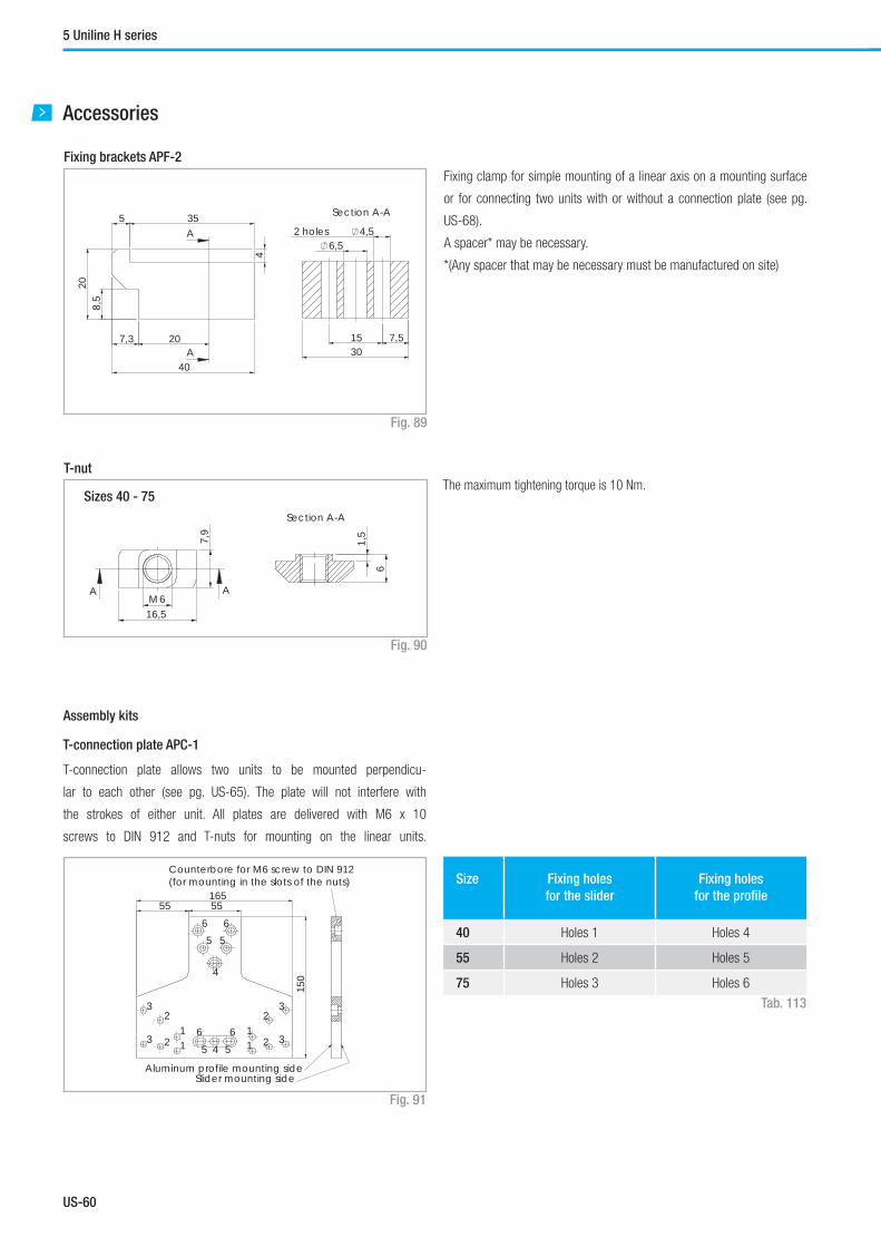
US-60
5 Uniline H series
Accessories
Fixing brackets APF-2
Fixing clamp for simple mounting of a linear axis on a mounting surface
or for connecting two units with or without a connection plate (see pg.
US-68).
A spacer* may be necessary.
*(Any spacer that may be necessary must be manufactured on site)
Fig. 89
7,51530
6,52 holes 4,5
Section A-A5
4
208,
5
35
7,3
40
20
A
A
T-nut
The maximum tightening torque is 10 Nm.
Fig. 90
Sizes 40 - 75
16,5M6
7,9
A A
1,5
6
Section A-A
T-connection plate APC-1
T-connection plate allows two units to be mounted perpendicu-
lar to each other (see pg. US-65). The plate will not interfere with
the strokes of either unit. All plates are delivered with M6 x 10
screws to DIN 912 and T-nuts for mounting on the linear units.
Fig. 91
Size Fixing holes
for the slider
Fixing holes
for the profi le
40 Holes 1 Holes 4
55 Holes 2 Holes 5
75 Holes 3 Holes 6
Tab. 113
Note
This adapter plate can be used with types E and ED only to a limited
extent. For further information, please contact our Application Engineering
Department.
55 55165
150
11 1
1
2
2
2
2
3
3 3
3
4
4
5
5 5
56
6 6
6
Aluminum profile mounting side
Counterbore for M6 screw to DIN 912 (for mounting in the slots of the nuts)
Slider mounting side
Assembly kits

US-61
Uniline System
US
Size Fixing holes
for the slider
Fixing holes
for the profi le
40 Holes 1 Holes 4
55 Holes 2 Holes 5
75 Holes 3 Holes 6
Tab. 114
Fig. 92
Angle connection plate APC-2
allows the right angle mounting of two units. The trolley of one unit can
be mounted to the side of the other (see pg. US-66). The plate will not
interfere with the strokes of either unit. All plates are delivered with M6 x
10 screws to DIN 912 and T-nuts for mounting to the linear units.
Note
This adapter plate can be used with types E and ED only to a limited
extent. For further information, please contact our Application Engineering
Department.75
165
8
1
1 1
1 2
2
2
2
3
3
3
3
Aluminum profile mounting side
873 4
5566
Slider mounting side
Counterbore for M6 screw to DIN 912 (for mounting in the slots of the nuts)
X connection plate APC-3
X connection plate for mounting two sliders perpendicular to each other
(see pg. US-67). The plate will not interfere with the strokes of either unit.
All plates are delivered with M6 x 10 screws to DIN 912 and T-nuts for
mounting on the linear units.
Fig. 93
Size Fixing holes
for slider 1
Fixing holes
for slider 2
40 Holes 1 Holes 4
55 Holes 2 Holes 5
75 Holes 3 Holes 6
Tab. 115
52,5 55160
52,5
55160 1 1
1 1
2 2
2 23
3 3
3
4 4
4 4
55
556 6
66
10
Counterbore for M6 screw to DIN 912(for mounting in the slots of the nuts)

US-62
Ordering key
Identifi cation code for Uniline linear unit
Ordering example: UH 07 1A 1190 1A D 500 L 350
Ordering key
In order to create identifi cation codes for Actuator Line, you can visit: http://confi gureactuator.rollon.com
U H 07
04=40
05=55
07=75
1A 1190 1A D 500 L 350
Indices of long slider plate
see pg. US-56 - US-57 - US-58
Indices of double slider plate, distance of the centers of slider plates see pg. US-56 - US-57 - US-58
Profi le/Rail code
L= Total length of the unit
Driving head code
Size see pg. US-56 - US-57 - US-58
Type
Uniline prefi x

US-63
Uniline System
US
Belt tension
All Uniline linear axes are all supplied with a standard belt tension suitable
for most applications (see tab. 116).
Fig. 94
AA BB
CC
Size 40 55 75 ED75 100
Belt tension [N] 160 220 800 1000 1000
Tab. 116
The belt tensioning system (located at the ends of the slider plates for
sizes 45 to 75, and at the deflection head for size 100) allows the toothed
belt tension to be set in accordance with requirements.
To set the belt tension for sizes 40 to 75, the following steps must be fol-
lowed (the reference values are standard values):
1. Determine the deviation of the belt tension from the standard value.
2. Figures 95 and 96 show how many turns the belt tensioning screws B
must be for the required belt tension deviation.
3. Calcualte the length of the belt (m), with the formula:
L = 2 x stroke (m) + 0.515 m (size 40);
L = 2 x stroke (m) + 0.630 m (size 55);
L = 2 x stroke (m) + 0.792 m (size 75).
4. Multiply the number of turns (see step 2) by the toothed belt length m
(see step 3) to calculate the required number of turns to achieve the
new desired belt tension..
5. Unscrew the safety screw C.
6. Turn the belt tensioning screws B in accordance with the above expla-
nation. Re-tighten the safety screw C.
Belt
tens
ion
[N]
Turns of the belt screw B per metre of toothed belt [U/m]
00
100
200
300
400
0,5 1 1,5 2
Size 40Size 55
Fig. 95
Belt
tens
ion
[N]
Turns of the belt screw B per metre of toothed belt [U/m]
00
500
1000
1500
0,5 1 1,5 2
Size 75
Fig. 96
Example:
Increasing the belt tension from 220 N to 330 N for an A55 - 1070:
1. deviation = 330 N - 220 N = 110 N.
2. Figures 95 and 96 show that the value by which the belt tensioning
screws B must be turned to increase the belt tension by 110 N is 0.5
turns.
3. Formula for calculating the toothed belt length:
L = 2 x stroke (m) + 0.630 m = 2 x 1.070 + 0.630 = 2.77 m.
4. This means that the required number of turns is:
0.5 rpm x 2.77 m = 1.4 turns.
5. Unscrew the safety screw C.
6. Turn the belt tensioning screws B by 1.4 turns with the aid of an exter-
nal reference.
7. Re-tighten the safety screw C.

US-64
6 Belt tension
Fig. 97
Belt tension A100
Belt
tens
ion
[N]
Offset of the belt deflection pulley A in mm per metre of stroke
00
500
1000
1500
2000
0,5 1 1,5 2
Fig. 98
To set the belt tension for size 100, the following steps must be followed
(the reference values are standard values):
1. Determine the deviation of the belt tension from the standard value.
2. Figure 97 shows how far the belt deflection pulley must be offset at the
deflection head via the set screws A, in order to obtain the desired belt
tension.
3. Multiply the offset by the stroke length.
4. Turn the set screws A in accordance with the above explanation.
Example:
Increasing the belt tension from 1000 N auf 1500 N for an
A100-2000:
1. Deviation = 1500 N - 1000 N = 500 N.
2. The graphic shows that the offset of the belt deflection pulley required
for increasing the belt tension by 500 N is 0.5 mm per metre of stroke.
Offset = 0.5 mm x 2 (stroke) = 1 mm
Note:
If the linear unit is used such that the load acts directly on the toothed
belt, it is important not to exceed the specified values for the belt tension.
Otherwise, the positional accuracy and stability of the toothed belt cannot
be guaranteed. If higher values are required for the belt tension, please
contact our Application Engineering Department.
AA
AA

US-65
Uniline System
US
Motor adapter plates AC2 and AC1-P, sizes 40 - 75
To connect the linear units to the motor and gearbox, suitable adapter
plates must be used. Rollon offers these plates in two different designs
(see chapter Accessories), except for size A100. The standard plates are
already provided with the holes required for mounting to the linear unit.
The fixing holes must be made on site. Ensure that the mounted plate will
not interfere with the stroke of the traversing slider plate.
Connection to motor and gearbox
1. Attach the motor adapter plate to the motor or gearbox.
2. Connect the T-nuts by inserting the screws without tightening them and
align the nuts in parallel to the slots of the unit.
3. Insert the connecting shaft into the drive head by aligning the key in
the key slot.
4. Attach the motor adapter plate to the drive head of the linear axis by
means of nuts and make sure that the nuts in the slots were rotated by
90° (see Accessories). Ensure correct fit of the adapter plate.
Fig. 99
Note:
■ The connecting plates for the Uniline A40 are delivered with four fixing
holes, even though only two holes are required for the connection. The
presence of four holes give the plate a symmetric design which allows
it to be used on any side of the unit.
■ Due to the constructive design of the aluminum profile, only
three fixing holes can be used the for the Uniline C series.
(see pg. US-22, fig. 32).
Installation instructions
Connection of two linear axes is achieved by means of the T-connection
plate APC-1 (see chapter Accessories). To mount the above-mentioned
configuration, the following steps should be carried out:
1. Prepare the connection plate by inserting the screws into the existing
holes on the APC-1 (see fig. 100).
2. Connect the T-nuts by introducing the screws without tightening them
and align the nuts in parallel to the slots of the unit.
3. Place the plate against the long side of unit 1 and tighten the screws.
Ensure that the nuts in the slots were rotated by 90°.
4. To fasten the plate to unit 2, insert the screws from the the long side of
unit 1 (see fig. 101).
5. Connect the T-nuts by introducing the screws without tightening them
and align the nuts in parallel to the slots of the slider plate of unit 2.
6. Place the plate against the slider plate and tighten the screws. Impor-
tant: Please make sure that the nuts in the slots were rotated by 90°.
T-connection plate APC-1, sizes 40 - 75
Fig. 101
Fig. 100
11
11
22

US-66
The connection of the two units is attained by means of the parallel slider
plates and the drive heads. For this configuration, we recommend using
our connection plate APC-1.
Example 1: System consisting of 2 X-axes and 1 Y-axis
Fig. 102
Connection of two linear axes is achieved by means of the angle con-
nection plate APC-2. To mount the above-mentioned configuration, the
following steps should be carried out:
1. Insert the screws to be used for the connection to unit 1 into the pre-
pared holes (see fig. 103).
2. Connect the T-nuts by inserting the screws without tightening them and
align the nuts in parallel to the slots of the slider plates.
3. Place the connection plate against the slider plate and tighten the
screws. Ensure that the nuts in the slots were rotated by 90°.
4. To fix the connection plate to unit 2, insert the screws into the prepared
holes on the short plate side (see fig. 104).
5. Connect the T-nuts by inserting the screws without tightening them and
align the nuts in parallel to the slots of the aluminum profile of unit 2.
6. Place the connection plate against the slider plate and tighten
the screws. Ensure that the nuts in the slots were rotated by 90°.
Angle connection plate APC-2, sizes 40 - 75
Fig. 103
11
Fig. 104
11
22
With this configuration, the Z-axis is connected to the slider plate of the
X-axis by means of the angle connection plate APC-2.
Example 2 – System consisting of 1 X-axis and 1 Z-axis
Fig. 105
7 Installation instructions

US-67
Uniline System
US
Connection of the two linear axes is achieved by means of the X connec-
tion plate APC-3 (see chapter Accessories). To mount the above-men-
tioned configuration, the following steps should be carried out:
1. Insert the screws from one side of the connection plate into the pre-
pared holes (see fig. 106).
2. Connect the T-nuts by inserting the screws without tightening them and
align the nuts in parallel to the slots of the slider plate of unit 1.
3. Place the connection plate against the slider plate and tight-
en the screws. Ensure that the nuts in the slots were rotated
by 90°.
4. Insert the screws from the other side of the connection plate (see fig.
107).
5. Connect the T-nuts by inserting the screws without tightening them and
align the nuts in parallel to the slots of the slider plate of unit 2.
6. Place the connection plate against the slider plate and tighten the
screws. Ensure that the nuts in the slots were rotated by 90°.
Fig. 106
X connection plate APC-3, sizes 40 - 75
Fig. 107
11
11
22
Connect four linear units to create a 3-axis gantry. The vertical axis is
arranged to be self-supporting on the central unit. To do so, connect
the two slider plates to each other, using the X connection plate APC-3.
Example 3 – System consisting of 2 X-axes, 1 Y-axis and 1 Z-axis
Fig. 108
The connection of the two parallel axes to the central unit is attained by
means of the T-connection plate APC-1.

US-68
7 Installation instructions
The connection of the Y-axis to the parallel slider plates is attained via the
fixing clamps APF-2.
Example 4 – System consisting of 1 Y-axis and 2 Z-axes
Fig. 110
Connection of two linear axes is achieved by means of the fixing clamps
APF-2 (see chapter Accessories). To mount the above-mentioned con-
figuration, the following steps should be carried out:
1. Insert the fastening screws into the clamp and, if necessary, place a
spacer* between the clamp and the slider plate.
*(Any spacer that is to be used must be manufactured on site)
2. Connect the T-nuts by inserting the screws without tightening them and
align the nuts in parallel to the slots of the slider plates.
3. Insert the projecting part of the clamp into the lower slot of the alu-
minum profile of unit 1.
4. Position the clamp lengthwise according to the desired position of the
slider plate of unit 2.
Fig. 109
Fixing clamp APF-2, sizes 40 - 75
11
22
5. Tighten the fastening screws. Ensure that the nuts in the slots were
rotated by 90°.
6. Repeat this operation for the required number of fixing clamps.

US-69
Uniline System
US
Notes


Precision System

PS-2
TH linear actuators are rigid and compact, ball screw driven linear units,
that enable high positioning accuracy and repeatability in all process phas-
es. With optimal performance assured, TH actuators have a repeatability
within 5 μm.
Thrust force transmission is achieved by means of super high effi cient ball
screws, which are available in several precision classes and a variety of
leads. Linear motion is based on two or four preloaded re-circulating ball
bearing blocks, with ball retainer technology, mounted on two precision
aligned parallel rails. The TH series is available in single carriage or double
carriage versions to meet different load requirements.
The TH linear units also feature safe rail and screw lubrication through a
dedicated channel for each component. The incredibly compact structure
of the TH actuator makes it the ideal solution for applications where space
is limited.
■ Extremely compact dimensions
■ High positioning accuracy
■ High load capacity and stiffness
■ Preloaded ball screw
■ Block with ball retainer
■ Internal protected rails and ball screw
■ Safe lubrication through dedicated channels
for each component (block and ball screw)
1 TH series
Fig. 1
TH series description
TH series

PS-3
Precision System
PS
The components
Aluminum base unit and carriage
The anodized extrusions used for the profi le and carriages of the Rollon
TH-series linear units were designed and manufactured in cooperation
with industry experts to achieve high-level accuracy and to maximize me-
chanical properties. The anodized aluminum alloy 6060 used and was ex-
truded with dimensional tolerances complying with UNI 3879 standards.
Linear motion system
Precision ball bearing guides with ground rails and preloaded blocks are
used on Rollon TH series linear units. Use of this technology makes it pos-
sible to obtain the following features:
■ High accuracy running parallelism
■ High positioning accuracy
■ High level of rigidity
■ Reduced wear
■ Low resistance to movement
Drive system
Rollon TH-series linear units use precision ball screws with either preload-
ed or non-preloaded ball screw nuts. The standard precision class of the
ball screws used is ISO 7, however ISO 5 precision class is also available
upon request. The ballscrew on the TH unit is available in different diam-
eters and leads (see specifi cations tables). Use of this type of technology
makes it possible to obtain the following features:
■ High speed (for long pitch screws)
■ High load capacity and accurate thrust forces
■ Superior mechanical performance
■ Reduced wear
■ Low resistance to movement
Protection
Rollon TH series linear units are equipped with sealing strips in order to
protect the mechanical components inside the linear unit against contami-
nants. In addition, the ball bearing guides and ball screws have their own
protection system, including scrapers and lip seals to remove contami-
nates from the raceways of the ball bearings.
General data about aluminum used: AL 6060
Chemical composition [%]
Physical characteristics
Mechanical characteristics
AI Mg Si Fe Mn Zn Cu Impurites
Remainder 0.35-0.60 0.30-0.60 0.30 0.10 0.10 0.10 0.05-0.15
Density Coeff. of
elasticity
Coeff. of thermal expansion
(20°-100°C)
Thermal conductivity
(20°C)
Specifi c heat
(0°-100°C)
Resistivity Melting point
kg___
dm3
kN___
mm2
10-6
___
K
W_____
m . K
J_____
kg . K
Ω . m . 10-9 °C
2.7 69 23 200 880-900 33 600-655
Rm Rp (02) A HB
N___
mm2
N___
mm2
% __
205 165 10 60-80
Tab. 1
Tab. 2
Tab. 3

PS-4
TH 90 SP2
hole M3x6 for ball screw lubrication hole M3x6 for right block lubrication
Lubrication Holes
L = 32 + 34 + 85 + USEFUL STROKE + SAFETY
hole M3x6 for left block lubrication Ø 4x6 H7 (2x)
M4x8 (4x)
21
54
Ø 8
h7
35
20 32 34
27
70.5
45.5 25
TH 90 SP2 Dimensions (single carriage)
Type
TH 90 SP2
Max. useful stroke length [mm] 665
Max. speed [m/s] See page PS-12
Carriage weight [kg] 0.65
Zero travel weight [kg] 1.41
Weight for 100 mm useful stroke [kg] 0.6
Technical data
Tab. 4
Type Fy
[N]
Fz
[N]
Mx
[Nm]
My
[Nm]
Mz
[Nm]
Stat. Dyn. Stat. Dyn. Stat. Dyn. Stat. Dyn. Stat. Dyn.
TH 90 SP2 6930 4616 6930 4616 188 126 26 17 26 17
Type Fx
[N]
Screw Stat. Dyn.
TH 90 SP212-05 9000 4300
12-10 6600 3600
TH 90 SP2 - Load capacity
TH 90 SP2 - Load capacity FX
See verifi cation under static load and lifetime on page SL-2 and SL-3 Tab. 8
Tab. 5
Type Ix
[107 mm4]
Iy
[107 mm4]
Ip
[107 mm4]
TH 90 SP2 0.0130 0.0968 0.1098
Type Max. positioning
precision [mm/300mm]
Max. repeatability
precision [mm]
ISO 5 ISO 7 ISO 5 ISO 7
TH 90 / 12-05 0.023 0.05 0.02 0.02
TH 90 / 12-10 0.023 0.05 0.02 0.02
Moments of inertia of the aluminum body
Ball screw precision
Tab. 6
Tab. 7
Fig. 2
Fx
MzFz
Mx
FyMy
1 TH series

PS-5
Precision System
PS
Type Max. positioning
precision [mm/300mm]
Max. repeatability
precision [mm]
ISO 5 ISO 7 ISO 5 ISO 7
TH 90 / 12-05 0.023 0.05 0.02 0.02
TH 90 / 12-10 0.023 0.05 0.02 0.02
Ball screw precision
TH 90 SP4
21Ø
8 h
7
35
20 32
125 2565
45.5 79.5 25
34
27
54
35 Lubrication Holes
L = 32 + 34 + 150 + USEFUL STROKE + SAFETY
hole M3x6 for right block lubrication hole M3x6 for right block lubrication
hole M3x6 for left block lubrication hole M3x6 for left block lubrication
M4x8 (4x)Ø 4x6 H7 (4x)
hole M3x6 for ball screw lubrication
TH 90 SP4 Dimensions (dual carriage)
Type
TH 90 SP4
Max. useful stroke length [mm] 600
Max. speed [m/s] See page PS-12
Carriage weight [kg] 0.90
Zero travel weight [kg] 2.04
Weight for 100 mm useful stroke [kg] 0.6
Technical data
Tab. 9
Type Fy
[N]
Fz
[N]
Mx
[Nm]
My
[Nm]
Mz
[Nm]
Stat. Dyn Stat. Dyn Stat. Dyn Stat. Dyn Stat. Dyn
TH 90 SP4 13860 9232 13860 9232 377 251 450 300 450 300
Type Fx
[N]
Screw Stat. Dyn
TH 90 SP412-05 9000 4300
12-10 6600 3600
TH 90 SP4 - Load capacity
TH 90 SP4 - Load capacity FX
See verifi cation under static load and lifetime on page SL-2 and SL-3 Tab. 13
Type Ix
[107 mm4]
Iy
[107 mm4]
Ip
[107 mm4]
TH 90 SP4 0.0130 0.0968 0.1098
Moments of inertia of the aluminum body
Fx
MzFz
Mx
FyMy
Tab. 11
Tab. 12Tab. 10
Note: for SP4 model the load capacities are valid only when the sliders are fi xed together
Fig. 3

PS-6
TH 110 SP2
hole M5x8 for ball screw lubrication hole M5x8 for right block lubrication
Lubrication Holes
L = 36 + 39 + 89 + USEFUL STROKE + SAFETY
hole M5x8 for left block lubrication Ø 5x8 H7(2x)
M5x8 (4x)
25.5
66
Ø 1
1 h7
39
32 36 39
30
88.5
38.5 50
TH 110 SP2 Dimensions (single carriage)
Type
TH 110 SP2
Max. useful stroke length [mm] 1411
Max. speed [m/s] See page PS-12
Carriage weight [kg] 0.76
Zero travel weight [kg] 2.65
Weight for 100 mm useful stroke [kg] 0.83
Technical data
Tab. 14
Tab. 15
Type Fy
[N]
Fz
[N]
Mx
[Nm]
My
[Nm]
Mz
[Nm]
Stat. Dyn. Stat. Dyn. Stat. Dyn. Stat. Dyn. Stat. Dyn.
TH 110 SP2 24200 14560 24200 14560 774 466 132 74 132 74
Type Fx
[N]
Screw Stat. Dyn.
TH 110 SP2
16-05 17195 12640
16-10 13420 9900
16-16 13900 9900
TH 110 SP2 - Load capacity
TH 110 SP2 - Load capacity FX
See verifi cation under static load and lifetime on page SL-2 and SL-3 Tab. 18
Type Ix
[107 mm4]
Iy
[107 mm4]
Ip
[107 mm4]
TH 110 SP2 0.0287 0.2040 0.2327
Moments of inertia of the aluminum body
Fx
MzFz
Mx
FyMy
Tab. 16
Tab. 17
Fig. 4
1 TH series
Type Max. positioning
precision [mm/300mm]
Max. repeatability
precision [mm]
ISO 5 ISO 7 ISO 5 ISO 7
TH 110 / 16-05 0.023 0.05 0.005 0.045
TH 110 / 16-10 0.023 0.05 0.005 0.045
TH 110 / 16-16 0.023 0.05 0.005 0.045
Ball screw precision

PS-7
Precision System
PS
Tab. 20
Fx
MzFz
Mx
FyMy
TH 110 SP4
25.5
Ø 1
1 h7
39
32 36
146.5 2085
38.5 108 20
39
30
66
39 Lubrication Holes
L = 36 + 39 + 175 + USEFUL STROKE + SAFETY
hole M5x8 for right block lubrication hole M5x8 for right block lubrication
hole M5x8 for left block lubrication hole M5x8 for left block lubrication
M5x8 (4x)Ø5x8 H7 (4x)
hole M5x8 for ball screw lubrication
TH 110 SP4 Dimensions (Dual carriage)
Type
TH 110 SP4
Max. useful stroke length [mm] 1325
Max. speed [m/s] See page PS-12
Carriage weight [kg] 1.26
Zero travel weight [kg] 4.00
Weight for 100 mm useful stroke [kg] 0.83
Technical data
Tab. 19
Type Fy
[N]
Fz
[N]
Mx
[Nm]
My
[Nm]
Mz
[Nm]
Stat. Dyn Stat. Dyn Stat. Dyn Stat. Dyn Stat. Dyn
TH 110 SP4 48400 29120 48400 29120 1549 932 1356 816 1356 816
Type Fx
[N]
Screw Stat. Dyn
TH 110 SP4
16-05 17195 12640
16-10 13420 9900
16-16 13900 9900
TH 110 SP4 - Load capacity
TH 110 SP4 - Load capacity FX
See verifi cation under static load and lifetime on page SL-2 and SL-3 Tab. 23
Type Ix
[107 mm4]
Iy
[107 mm4]
Ip
[107 mm4]
TH 110 SP4 0.0287 0.2040 0.2327
Moments of inertia of the aluminum body
Tab. 21
Tab. 22
Note: for SP4 model the load capacities are valid only when the sliders are fi xed together
Fig. 5
Ball screw precision
Type Max. positioning
precision [mm/300mm]
Max. repeatability
precision [mm]
ISO 5 ISO 7 ISO 5 ISO 7
TH 110 / 16-05 0.023 0.05 0.005 0.045
TH 110 / 16-10 0.023 0.05 0.005 0.045
TH 110 / 16-16 0.023 0.05 0.005 0.045

PS-8
1 TH series
TH 145 SP2
hole M5x10 for ball screw lubrication hole M5x10 for right block lubrication
Lubrication Holes
L = 44 + 45 + 110 + USEFUL STROKE + SAFETY
hole M5x10 for left block lubrication Ø 6x10 H7 (2x)
M6x12 (4x)
34
88
Ø 1
4 h7
49
44 44 45
36
115
45 70
TH 145 SP2 Dimensions (single carriage)
Type
TH 145 SP2
Max. useful stroke length [mm] 1690
Max. speed [m/s] See page PS-12
Carriage weight [kg] 1.45
Zero travel weight [kg] 5.9
Weight for 100 mm useful stroke [kg] 1.6
Technical data
Tab. 24
Tab. 25
Type Fy
[N]
Fz
[N]
Mx
[Nm]
My
[Nm]
Mz
[Nm]
Stat. Dyn. Stat. Dyn. Stat. Dyn. Stat. Dyn. Stat. Dyn.
TH 145 SP2 43400 34800 43400 34800 1888 1514 310 240 310 240
Type Fx
[N]
Screw Stat. Dyn.
TH 145 SP2
20-05 23545 14700
20-20 19445 12250
25-10 29573 16270
TH 145 SP2 - Load capacity
TH 145 SP2 - Load capacity FX
See verifi cation under static load and lifetime on page SL-2 and SL-3 Tab. 28
Type Ix
[107 mm4]
Iy
[107 mm4]
Ip
[107 mm4]
TH 145 SP2 0.090 0.659 0.749
Moments of inertia of the aluminum body
Fx
MzFz
Mx
FyMy
Tab. 26
Tab. 27
Fig. 6
Type Max. positioning
precision [mm/300mm]
Max. repeatability
precision [mm]
ISO 5 ISO 7 ISO 5 ISO 7
TH 145 / 20-05 0.023 0.05 0.005 0.045
TH 145 / 20-20 0.023 0.05 0.005 0.045
TH 145 / 25-10 0.023 0.05 0.005 0.045
Ball screw precision

PS-9
Precision System
PS
TH 145 SP4
34Ø
14
h7
49
44 44
174 30100
45 129 30
45
36
88
49 Lubrication Holes
L = 44 + 45 + 210 + USEFUL STROKE + SAFETY
hole M5x10 for right block lubrication hole M5x10 for right block lubrication
hole M5x10 for left block lubrication hole M5x10 for left block lubrication
M6x12 (4x)Ø 6x10 H7 (4x)
hole M5x10 for ball screw lubrication
TH 145 SP4 Dimensions (dual carriage)
Type
TH 145 SP4
Max. useful stroke length [mm] 1590
Max. speed [m/s] See page PS-12
Carriage weight [kg] 2.42
Zero travel weight [kg] 8.3
Weight for 100 mm useful stroke [kg] 1.6
Technical data
Tab. 29
Type Fy
[N]
Fz
[N]
Mx
[Nm]
My
[Nm]
Mz
[Nm]
Stat. Dyn. Stat. Dyn. Stat. Dyn. Stat. Dyn. Stat. Dyn.
TH 145 SP4 86800 69600 86800 69600 3776 3028 2855 2290 2855 2290
Type Fx
[N]
Screw Stat. Dyn.
TH 145 SP4
20-05 23545 14700
20-20 19445 12250
25-10 29573 16270
TH 145 SP4 - Load capacity
TH 145 SP4 - Load capacity FX
See verifi cation under static load and lifetime on page SL-2 and SL-3 Tab. 33
Type Ix
[107 mm4]
Iy
[107 mm4]
Ip
[107 mm4]
TH 145 SP4 0.090 0.659 0.749
Moments of inertia of the aluminum body
Fx
MzFz
Mx
FyMy
Tab. 31
Tab. 32
Note: for SP4 model the load capacities are valid only when the sliders are fi xed together
Fig. 7
Tab. 30
Type Max. positioning
precision [mm/300mm]
Max. repeatability
precision [mm]
ISO 5 ISO 7 ISO 5 ISO 7
TH 145 / 20-05 0.023 0.05 0.005 0.045
TH 145 / 20-20 0.023 0.05 0.005 0.045
TH 145 / 25-10 0.023 0.05 0.005 0.045
Ball screw precision

PS-10
Tab. 34
Fig. 8
Motor connections
E (4x)
D (4x)
D (4x)
Detail 1 (TH 145, TH 110)
Detail 2 (TH 145, TH 110, TH 90)
B
Ø A
H7 Ø
F h
7
3425
.5
CI L 40
ZR
UQ
VT
P SH H
70
Ø 60
30°
30°
28
M
G
N
G
O
E (4x)
TH 110
TH 145
G
29
D (4x)
H
L
21
I
M
N
==
= =H
4,5
Q
3,4
TH 90
Detail 3 (TH 90)
2
3
2
1
LI
M
H
==
==
Type A B C D E F G H I L M N O P Q R S T U V Z
TH 90 28 2.5 20 M4x8 - 8 41 8 40 39 90 4 4.5 - 4.8 - - 5.5 3.8 2.7 1.3
TH 110 40 2.5 32 M4x8 M6x10 11 40 10 50 49 110 4 9.5 8 4.8 2.5 5.2 5.5 3.8 2.7 1.3
TH 145 48 2.5 44 M6x10 M6x12 14 40 12 65 64 145 4 9.5 8 5.7 2.5 5.2 5.5 3.8 2.7 1.3
1 TH series
Units [mm]

PS-11
Precision System
PS
Tab. 37
Tab. 35
Tab. 36
Lubrication
SP linear units with ball bearing guides
SP Linear units are equipped with self lubricating linear ball guides. The
ball bearing carriages of the SP versions are also fi tted with a retention
cage that eliminates "steel-steel" contact between adjacent revolving
parts and prevents misalignment of these in the circuits.
Special lubrication reservoirs are mounted on the front plates of the linear
blocks which continuously provide the necessary amount of grease to the
ball raceways under load. These lubrication reservoirs also considerably
reduce the frequency of lubrication of the module. This system guarantees
a long interval between maintenances: SP version: every 5000 km or 1
year of use, based on the value reached fi rst. If a longer service life is
required or in case of high dynamic or high loaded applications please
contact our offi ces for further verifi cation.
Amount of lubricant needed to lubricate carriages:
Type Quantity [ g ]
TH 90 1
TH 110 0.8
TH 145 1.4
Fig. 9
Fig. 10
Fig. 11
Fig. 12
■ Insert grease gun into the specifi c grease nipples.
■ Type of lubrifi cant: Lithium soap grease of class NLGI 2.
■ For specially stressed applications or difficult enviromental
conditions, lubrication should be carried out more frequently.
Apply to Rollon for futher advice.
Hole for lubrication of left block
Hole for lubrication of right block Hole for lubrication of ball screw
Ball screws
The ball screw nuts for the Rollon TH series linear slides should be
re-lubricated every 50 million revolutions. Use the following conver-
sion table to determine the re-lubrication interval in linear distance
traveled (km) as shown.
TypeQuantity [g]
for grease nipple
12-05 0.3
12-10 0.3
16-05 0.6
16-10 0.8
16-16 1.0
20-05 0.9
20-20 1.7
25-10 1.7
Comparison table for no.
of revolutions/linear distance
Turns 50 ·106
Lead 5 250 km
Lead 10 500 km
Lead 16 750 km
Lead 20 1000 km
Hole for lubrication of block 2
Hole for lubrication of ball screw Hole for lubrication of block 3
Hole for lubrication of block 4
Hole for lubrication of block 1
Block 3 lubricator
(available only on SP4)
Block 4 lubricator
(available only on SP4)
Block 1 lubricator
Ball screw lubricator
Block 2 lubricator

PS-12
1 TH series
Critical speed
Calculation factors
The maximum linear speed of Rollon TH -series linear units depends on
the critical speed of the screw (based on its diameter and length) and on
the max. permissible speed of the ball screw nut used. The limit speed
for Rollon TH series units can be calculated using the following formula:
fV
max = ——— [m/s]
ln2
Screw diameter and lead Calculation factor (f) Critical length of the screw
( ln ) [mm]
12-05 0.629 ·105
LT - Culn = LT - ( ———— ) 2
12-10 1.258 ·105
16-05 1.487 ·105
16-10 3.160 ·105
16-16 5.230 ·105
20-05 2.155 ·105
20-20 8.608 ·105
25-10 5.352 ·105
LT = Total length
Cu = Useful stroke
Tab. 39
Tab. 40
Tab. 38
Screw diameter and lead Max. linear speed
of the bell screw nut [m/s]
ISO 7
Max. linear speed
of the bell screw nut [m/s]
ISO 5
12-05 0.56 0.69
12-10 1.11 1.39
16-05 0.42 0.52
16-10 0.83 1.04
16-16 1.33 1.67
20-05 0.33 0.42
20-20 1.33 1.67
25-10 0.53 0.67
The maximum linear speed, which depends on the ball screw nut, is indicated directly in the table below.

PS-13
Precision System
PS
150
200
300
400
500
600
700
800
1,60
1,20
1,40
1,00
0,80
0,60
0,40
0,20
0,00
Critical speed on TH 90
1,60
1,80
1,20
1,40
1,00
0,80
0,60
0,40
0,20
0,00
200
300
400
500
600
700
800
900
1000
1100
1200
1300
1400
1500
1600
Critical speed on TH 110
1,60
1,80
1,20
1,40
1,00
0,80
0,60
0,40
0,20
0,00
200
300
400
500
600
700
800
900
1000
1100
1200
1300
1400
1500
1600
1700
1800
1900
Critical speed on TH 145
V m
ax [m
/s]
V m
ax [m
/s]
V m
ax [m
/s]
L [mm]
L [mm]
L [mm]
20x05 ISO7
20x05 ISO520x10 ISO7
20x10 ISO5
20x20 ISO7
20x20 ISO5
16x05 ISO7
16x10 ISO7
16x16 ISO7
16x05 ISO5
16x10 ISO5
16x16 ISO5
12x10 ISO5
12x05 ISO5
12x05 ISO7
12x10 ISO7
Fig. 13

PS-14
1 TH series
Accessories
H
C E
D
L
Counterbore holes
L
A
B
L
B
B
B
A
Fixing brackets
Fixing by brackets
T nuts
A
B MOD. 1
MOD. 2
A
Type A
Unit mm
TH 90 102
TH 110 126
TH 145 161
Type A B C
TH 90 Mod. 2 M5 - Mod. 1 M2.5
TH 110 Mod. 2 M5 Mod. 1 M4 Mod. 1 M2.5
TH 145 Mod. 2 M6 Mod. 1 M4 Mod. 1 M2.5
Code 6000436 (M5)/6000437 (M6) 963.0407.81 6001361
Type N°
holes
Counterbore
for screw
A B C D E H L Code
Rollon
TH 90
2 M4 11 40 10.5 4.5 14.5 9.1 62 1003385
4 M4 8.5 30 10.5 4.5 14.5 9.1 107 1003509
4 M4 8.5 20 10.5 4.5 14.5 9.1 77 1003510
1 M4 - - 10.5 4.5 14.5 9.1 25 1003612
TH 110
TH 145
4 M5 8.5 30 15 7 19.3 11.5 107 1002805
4 M6 11 40 15 7 19.3 11.5 142 1002864
1 M6 - - 15 7 19 11.5 25 1002970
2 M6 11 40 15 7 19 11.5 62 1002971
4 M5 20 20 15 7 19 11.5 100 1003311
Dimensions (mm)
Units (mm)
Units (mm)
Fig. 14
Fig. 15
Fig. 16
Tab. 41
Tab. 42
Tab. 43

PS-15
Precision System
PS
Proximity
B5
B4
H5
H
4
PROXIMITY SWITCH HOLDER
SENSOR DOG L4
L5
SENSOR DOG
PROXIMITY SWITCH HOLDER
B6
H6
L6
REED holder set
B4 B5 B6 L4 L5 L6 H4 H5 H6 Sensor Proximity
holder set
Sensor
dog
REED
holder set
TH 90 10 15 9.5 12 25 35 6 15 16 Ø 8 G001193 G001203 G001204
TH 110 10 15 9.5 30 25 35 12 15 16 Ø 8 G001193 G001198 G001204
TH 145 10 15 9.5 30 25 35 12 15 16 Ø 8 G001193 G001198 G001204
Units (mm)
Fig. 17
Tab. 44

PS-16
1 TH series
Coupling Motor bell Kit
External carriage for SP2
Type A B C D E F L Code
TH 90 90 16 15 20 20 6.8 60 G001195
TH 110 110 16 25 20 20 9.5 60 G001059
TH 145 145 20 19 40 27 9.5 80 G001062
External carriage
Fig. 18
Tab. 47
Tab. 45
External carriagefor SP4
Type A B C D E F L Code
TH 90 90 16 15 20 20 6.8 125 G001194
TH 110 110 16 25 20 20 9.5 150 G001060
TH 145 145 20 19 40 27 9.5 190 G001061
Tab. 46
A
B
C D E D
F
20
145
19 40 27 40
B
J
5,2
2,5 5,2
8
6 R1,5
6,9
TH90
16
90
15 20
I
K
L 8,2
2
x45°
8
7,2
45°
2,2
TH90-110
8,35 3
,5
3,5
9
10,
8 1
,5x4
5°
30°
3,5
TH145
B
A
C D E D AB
4,6
4,8
R1
4
0,8
4,5
DET.A
DET.B
TH110-145
Grease nipple for left slider(not available for SP2 version)
Grease nipplefor ball screw
Grease nipplefor left slider
Grease nipplefor right slider(not available for SP2 version)
Grease nipplefor right slider
see pg. PS-18

PS-17
Precision System
PS
Kit Code
TH 90 - TH 90 XY G001199
TH 90 - TH 110 XZ G001205
TH 110 - TH 110 XY G001080
TH 110 - TH 110 XZ G001083
TH 110 - TH 145 XY G001079
TH 110 - TH 145 XZ G001084
TH 145 - TH 145 XY G001081
TH 145 - TH 145 XZ G001085
Tab. 48
Fig. 19 Fig. 20
Assembly kits
While ordering two units for Y-Z assembly key has to be specifi ed that they work together in order to drill the trolleys for the assembly of the kit. For the direct assembly of TH linear units on multiple axis system Rollon offers dedicated assembly kits. The table below shows the allowed combina-
tions as well as the assembly kit codes.
X-Y X-Z

PS-18
1 TH series
Unit Ratio A B C D E F M Code
TH 110 1 : 1 Ø 40 Ø 63 40.5 Ø 14 233 88 M4 G001011
TH 110 1 : 1 Ø 50 Ø 70 40.5 Ø 14 233 88 M4 G001055
TH 110 1 : 1 Ø 60 Ø 75 40.5 Ø 14 233 88 M6 G001013
TH 145 1 : 1 Ø 80 Ø 100 52 Ø 14 273 100 M6 G000984
TH 145 1 : 1 Ø 95 Ø 115 52 Ø 19 273 100 M8 G000988
Unit D1 D2 D3 D4 L L3 Code
TH90 Ø 40 Ø 63 56 M5 50 3 G001192
TH110 Ø 60 Ø 75 65 M6 68 4 G001051
TH110 Ø 73,1 Ø 98,4 86 M5 76.7 2 G001074
TH110 Ø 60 Ø 75 65 M5 68 4 G001119
TH110 Ø 50 Ø 70 65 Ø 5.4 75 11 G001200
TH145 Ø 50 Ø 70 80x60 M4 92 21 G000979
TH145 Ø 70 Ø 85 80x85 M6 92 4 G001066
TH145 Ø 70 Ø 90 80x85 M5 92 5 G001067
TH145 Ø 80 Ø 100 90 M6 92 4 G001068
TH145 Ø 50 Ø 65 80x85 M5 92 21 G001069
TH145 Ø 60 Ø 75 80x85 M6 92 4 G001070
TH145 Ø 50 Ø 70 80x85 M5 92 21 G001071
TH145 Ø 73 Ø 98,4 85 M5 92 4 G001072
TH145 Ø 55 68X40 85x60 Ø6,4 82 11 G001073
Tab. 49
Tab. 50
Fig. 21
Fig. 22
Wrap around kit
For further information please contact Rollon Technical Dept.
A
D
B
M
E
F G
/2
G/2
C
D3
D1H7
D2
4 x D4
L
L3
Mounting of the motor
Rollon TH Series linear units can be supplied with different types of motor
mounts, adapter fl anges, and with torsionally stiff couplings for screw and
motor connections that enable fast, hassle-free assembly of the motors.
The types of bells available for the related units are shown in the table
motor mounts:
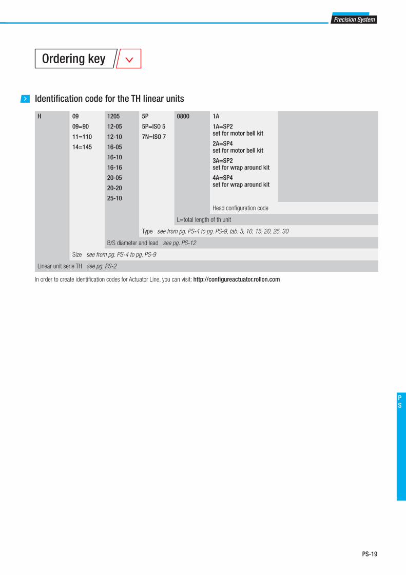
PS-19
Precision System
PS
Identifi cation code for the TH linear units
H 09
09=90
11=110
14=145
1205
12-05
12-10
16-05
16-10
16-16
20-05
20-20
25-10
5P
5P=ISO 5
7N=ISO 7
0800 1A
1A=SP2 set for motor bell kit
2A=SP4 set for motor bell kit
3A=SP2set for wrap around kit
4A=SP4 set for wrap around kit
Head confi guration code
L=total length of th unit
Type see from pg. PS-4 to pg. PS-9, tab. 5, 10, 15, 20, 25, 30
B/S diameter and lead see pg. PS-12
Size see from pg. PS-4 to pg. PS-9
Linear unit serie TH see pg. PS-2
Ordering key
In order to create identifi cation codes for Actuator Line, you can visit: http://confi gureactuator.rollon.com
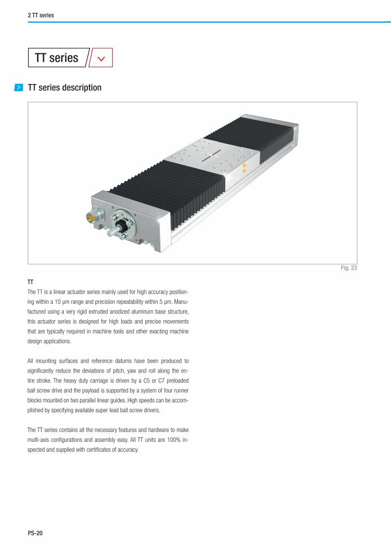
PS-20
TT series description
TT series
Fig. 23
2 TT series
TT
The TT is a linear actuator series mainly used for high accuracy position-
ing within a 10 μm range and precision repeatability within 5 μm. Manu-
factured using a very rigid extruded anodized aluminum base structure,
this actuator series is designed for high loads and precise movements
that are typically required in machine tools and other exacting machine
design applications.
All mounting surfaces and reference datums have been produced to
signifi cantly reduce the deviations of pitch, yaw and roll along the en-
tire stroke. The heavy duty carriage is driven by a C5 or C7 preloaded
ball screw drive and the payload is supported by a system of four runner
blocks mounted on two parallel linear guides. High speeds can be accom-
plished by specifying available super lead ball screw drivers.
The TT series contains all the necessary features and hardware to make
multi-axis confi gurations and assembly easy. All TT units are 100% in-
spected and supplied with certifi cates of accuracy.

PS-21
Precision System
PS
The components
Aluminum base unit and carriage
The base and carriages of the Rollon TT series linear units were designed
and manufactured in co-operation with industry experts to obtain the
high-level of accuracy and maximize mechanical properties. Anodized
aluminum alloy 6060 was used with dimensional tolerances complying
with UNI 3879 standards. To guarantee highly precise movement, the bod-
ies are precision machined on all outer surfaces and in the areas where
the mechanical components are fi tted, such as ball bearing guides and
ball screw supports.
Linear motion system
Precision ball bearing guides with ground rails and preloaded blocks are
used on Rollon TT series linear units. Use of this technology makes it pos-
sible to obtain the following features:
■ High accuracy running parallelism
■ High positioning accuracy
■ High level of rigidity
■ Reduced wear
■ Low resistance to movement
Drive system
Rollon TT-series linear units use precision ball screws with either preload-
ed or non-preloaded ball screw nuts. The standard precision class of the
ball screws used is ISO 5, however ISO 7 precision class is also available
upon request. The ballscrew on the TH unit is available in different diam-
eters and leads (see specifi cations tables). Use of this type of technology
makes it possible to obtain the following features:
■ High speed (for long pitch screws)
■ High load capacity and accurate thrust forces
■ Superior mechanical performance
■ Reduced wear
■ Low resistance to movement
Protection
Rollon TT-series linear units are equipped with bellows in order to protect
the mechanical and electrical components inside the linear unit against
contaminants. In addition to the bellows system, the ball bearing guides
and ball screws have their own protection including scrapers and lip seals
to remove contaminates from the raceways of the ball bearings.
General data about aluminum used: AL 6060
Chemical composition [%]
Physical characteristics
Mechanical characteristics
AI Mg Si Fe Mn Zn Cu Impurites
Remainder 0.35-0.60 0.30-0.60 0.30 0.10 0.10 0.10 0.05-0.15
Density Coeff. of
elasticity
Coeff. of thermal expansion
(20°-100°C)
Thermal conductivity
(20°C)
Specifi c heat
(0°-100°C)
Resistivity Melting point
kg___
dm3
kN___
mm2
10-6
___
K
W_____
m . K
J_____
kg . K
Ω . m . 10-9 °C
2.7 69 23 200 880-900 33 600-655
Rm Rp (02) A HB
N___
mm2
N___
mm2
% __
205 165 10 60-80
Tab. 51
Tab. 52
Tab. 53

PS-22
2 TT series
TT 100
TT 100 Dimensions
Fig. 24
50
6
h7 PC 120
48
PC CU
28
h7
15
29 5
26 400 20
G N x 100 G
LT = 166 + (2 x Pc) + Cu
SOCKET INDUCTIVE SENSORS(on demand, please see pag. PS-36)
INDUCTIVE SENSORS(on demand, please see pag. PS-36)
27,
5
50 50 23,1
29,
75
60
60°
4 x M4 10 98
50
27,
5
19,
5
59 85
100
7,5 7,5
A
7
3
6,4
11
3
12
19,
5
4,2
8,3
6,2
4
B
DETAIL ASCALE 2 : 3
LATERAL REFERENCE SURFACE
LATERAL REFERENCE SURFACE FOR CARRIAGE
DETAIL BSCALE 5 : 1
"V" REFERENCE
19
6
0
19
20 80 20
4 x M6 8

PS-23
Precision System
PS
Note: for the ballscrew 12/10 the max. useful stroke is 664 mm.
Useful stroke
CU [mm]
Total length LT
[mm]
G Dimension
[mm]
Weight
[ Kg ]
46 246 50 2.5
114 346 50 3
182 446 50 4
252 546 50 5
320 646 50 6
390 746 50 7
458 846 50 7
526 946 50 8
596 1046 50 9
664 1146 50 10
734 1246 50 11
802 1346 50 11
940 1546 50 13
Technical data
Type
TT 100
Max. speed [m/s] See page PS-33
Carriage weight [kg] 0.93
Technical data
Tab. 56
Type Fy
[N]
Fz
[N]
Mx
[Nm]
My
[Nm]
Mz
[Nm]
Stat. Dyn. Stat. Dyn. Stat. Dyn. Stat. Dyn. Stat. Dyn.
TT 100 14000 8985 14000 8985 385 247 490 314 490 314
Type Fx
[N]
Screw Stat. Dyn.
TT 100 12-05 12000 6600
TT 100 - Load capacity
TT 100 - Load capacity FX
See verifi cation under static load and lifetime on page SL-2 and SL-3 Tab. 59
Type Ix
[107 mm4]
Iy
[107 mm4]
Ip
[107 mm4]
TT 100 0.006 0.144 0.150
Moments of inertia of the aluminum body
Fx
MzFz
Mx
FyMy
Tab. 57
Tab. 54
Tab. 58
Tab. 55
Type Max. positioning
precision [mm/300mm]
Max. repeatability
precision [mm]
ISO 5 ISO 7 ISO 5 ISO 7
TT 100 / 12-05 0.023 0.05 - 0.010
TT 100 / 12-10 0.023 0.05 - 0.010
Ball screw precision

PS-24
2 TT series
TT 155
TT 155 Dimensions
Fig. 25
65,
5
10
h7 PC 150
59
CU PC
G G N X 120
30 LP 30 40
LT = 210 + (2 X PC) + CU
5
25
55
h7
A
INDUCTIVE SENSORS(on demand, please see pag. PS-36)
38
20
50 5
0
4 X M6 11
GREASE NIPPLELINEAR BLOCKS
GREASE NIPPLELINEAR BLOCKS
GREASE NIPPLEBALL SCREW NUT 1 153
3
60
3
3
23,
2
135 155
10 10
B
LATERAL REFERENCE SURFACE OF CARRIAGE
7
2,5
16,
2 5
5
6,4 10,4
DETAIL B
LATERAL REFERENCESURFACE
17,5 35 45 35 17,5 150
153
115
1
9
19
6 P
6
6 P6
80
36
8 X M6 10 DETAIL A
"V" REFERENCE
SOCKET INDUCTIVE SENSORS(on demand, please see pag. PS-36)
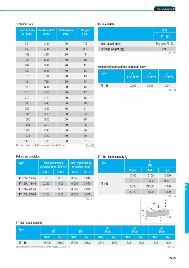
PS-25
Precision System
PS
Note: for the ballscrew Ø16 the max. useful stroke is 994 mm.
Useful stroke
CU [mm]
Total length LT
[mm]
G Dimension
[mm]
Weight
[ Kg ]
92 340 20 7.5
140 400 50 8.5
188 460 20 9
236 520 50 10
282 580 20 11
330 640 50 12
378 700 20 13
424 760 50 13
520 880 50 15
614 1000 50 17
710 1120 50 18
806 1240 50 20
900 1360 50 21
994 1480 50 23
1090 1600 50 25
1184 1720 50 26
1280 1840 50 28
1376 1960 50 30
1470 2080 50 31
Technical data Technical data
Type
TT 155
Max. speed [m/s] See page PS-33
Carriage weight [kg] 2.93
Tab. 62
Tab. 60
Type Fx
[N]
Screw Stat. Dyn.
TT 155
16-05 16100 12300
16-10 12300 9600
20-05 21500 14300
20-20 18800 13300
TT 155 - Load capacity FX
Type Ix
[107 mm4]
Iy
[107 mm4]
Ip
[107 mm4]
TT 155 0.009 0.531 0.54
Moments of inertia of the aluminum body
Tab. 63
Tab. 64
Type Fy
[N]
Fz
[N]
Mx
[Nm]
My
[Nm]
Mz
[Nm]
Stat. Dyn. Stat. Dyn. Stat. Dyn. Stat. Dyn. Stat. Dyn.
TT 155 48400 29120 48400 29120 2541 1529 1533 922 1533 922
TT 155 - Load capacity
See verifi cation under static load and lifetime on page SL-2 and SL-3 Tab. 65
Fx
MzFz
Mx
FyMy
Tab. 61
Type Max. positioning
precision [mm/300mm]
Max. repeatability
precision [mm]
ISO 5 ISO 7 ISO 5 ISO 7
TT 155 / 16-05 0.023 0.05 0.005 0.045
TT 155 / 16-10 0.023 0.05 0.005 0.045
TT 155 / 20-05 0.023 0.05 0.005 0.045
TT 155 / 20-20 0.023 0.05 0.005 0.045
Ball screw precision
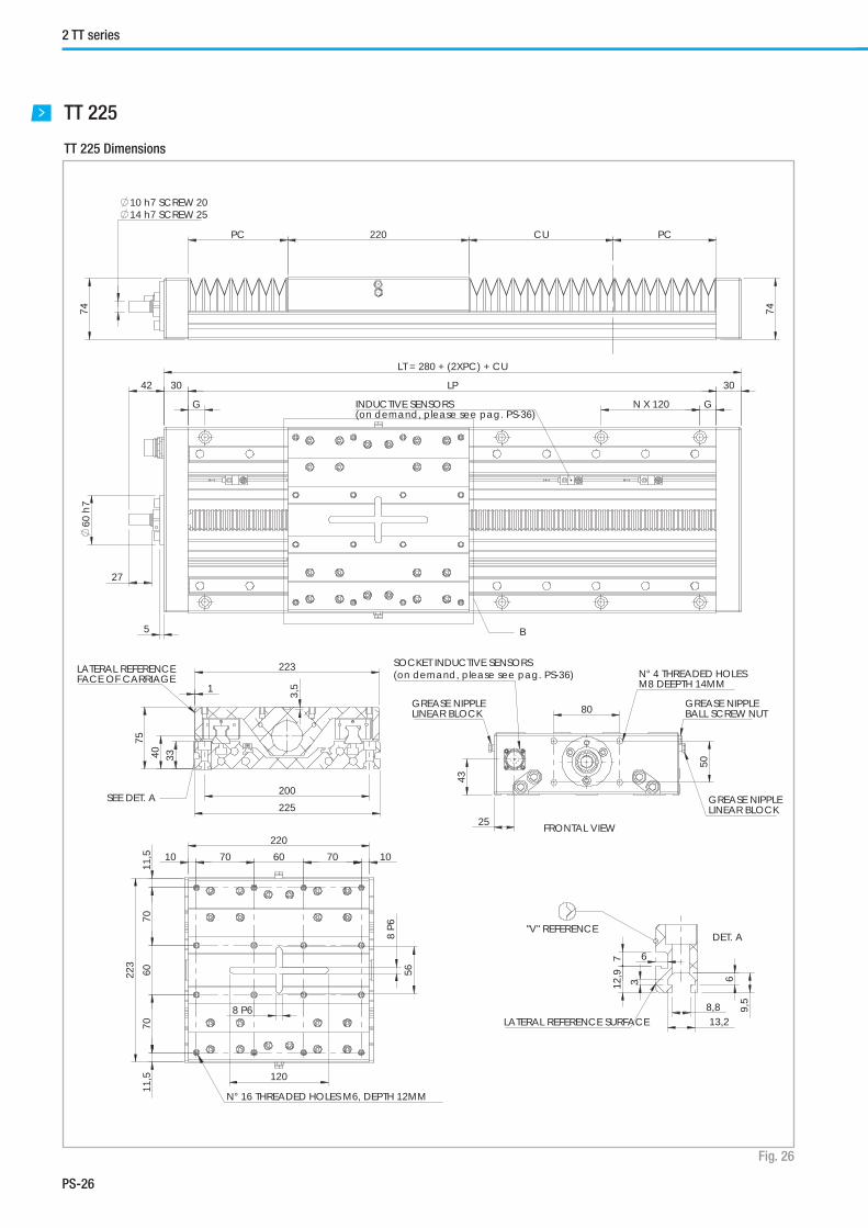
PS-26
2 TT series
TT 225
TT 225 Dimensions
Fig. 26
74
10 h7 SCREW 2014 h7 SCREW 25
PC 220
74
PC CU
27
60
h7
42 30 LP 30
G
5
LT = 280 + (2XPC) + CU
G N X 120
B
INDUCTIVE SENSORS(on demand, please see pag. PS-36)
25
43
80 5
0
GREASE NIPPLELINEAR BLOCK
GREASE NIPPLELINEAR BLOCK
GREASE NIPPLEBALL SCREW NUT
SOCKET INDUCTIVE SENSORS(on demand, please see pag. PS-36) N° 4 THREADED HOLES
M8 DEEPTH 14MM
75
4
0
33
3,5
1
223
225 200
SEE DET. A
LATERAL REFERENCEFACE OF CARRIAGE
9,5
6
3
8,8 13,2
12,
9 7
6
DET. A
LATERAL REFERENCE SURFACE
"V" REFERENCE
220
223
10 70 60 70 10
11,
5
70
6
0
70
1
1,5
8 P
6
8 P6
56
120
N° 16 THREADED HOLES M6, DEPTH 12MM
FRONTAL VIEW

PS-27
Precision System
PS
Note: for the ballscrew Ø20 the max. useful stroke is 1440 mm.
* For the indicated lengths Rollon does not guarantee the tolerance
values shown on pag. PS-31
Useful stroke
CU [mm]
Total length LT
[mm]
G Dimension
[mm]
Weight
[ Kg ]
92 400 50 15
144 460 20 16
196 520 50 17
248 580 20 19
300 640 50 20
352 700 20 21
404 760 50 23
508 860 50 25
612 1000 50 28
714 1120 50 31
818 1240 50 33
922 1360 50 36
1026 1480 50 39
1234 1720 50 44
1440 1960 50 49
1648* 2200 50 54
1856* 2440 50 60
2062* 2680 50 65
2270* 2920 50 70
Technical data
Tab. 66
Type Fx
[N]
Screw Stat. Dyn.
TT 225
20-05 21500 14300
20-20 18800 13300
25-05 27200 15900
25-10 27000 15700
25-25 23300 14700
TT 225 - Load capacity FX
Technical data
Type
TT 225
Max. speed [m/s] See page PS-33
Carriage weight [kg] 5.4
Tab. 68
Type Ix
[107 mm4]
Iy
[107 mm4]
Ip
[107 mm4]
TT 225 0.038 2.289 2.327
Moments of inertia of the aluminum body
Tab. 69
Tab. 70
Type Fy
[N]
Fz
[N]
Mx
[Nm]
My
[Nm]
Mz
[Nm]
Stat. Dyn. Stat. Dyn. Stat. Dyn. Stat. Dyn. Stat. Dyn.
TT 225 86800 69600 86800 69600 6944 5568 5642 4524 5642 4524
TT 225 - Load capacity
See verifi cation under static load and lifetime on page SL-2 and SL-3 Tab. 71
Fx
MzFz
Mx
FyMy
Tab. 67
TypeMax. positioning
precision [mm/300mm]
Max. repeatability
precision [mm]
ISO 5 ISO 7 ISO 5 ISO 7
TT 225 / 20-05 0.023 0.05 0.005 0.045
TT 225 / 20-20 0.023 0.05 0.005 0.045
TT 225 / 25-05 0.023 0.05 0.005 0.045
TT 225 / 25-10 0.023 0.05 0.005 0.045
TT 225 / 25-25 0.023 0.05 0.005 0.045
Ball screw precision

PS-28
2 TT series
TT 310
TT 310 Dimensions
Fig. 27
104
Ø 2
2 h7
104
CU PCLCPC
2055 49 LP
GN X 280G
42
13
Ø 8
5 h7
LT = 69+(2XPC)+LC+CU
307
55
30
105
310280
7676
120
65
49
M10 X 20
SOCKET SENSOR(on demand, please see pag. PS-36)GREASE NIPPLE BALL SCREW
NUT AND LINEAR GUIDE GREASE NIPPLE BALL SCREW NUT AND LINEAR GUIDE
SEE DETAIL "A" FRONTAL VIEW
320
52,5 76 63 76 52,5
290
8080
260
80 80(8X) M12 X 24
307
23,5
260
23,5
20 H920 h
9
DEEPTH 4.9 MM
15,5
24
13,5
DETAIL "A"

PS-29
Precision System
PS
* For the indicated lengths Rollon does not guarantee the tolerance
values shown on pag. PS-31
Useful stroke
CU [mm]
Total length LT
[mm]
G Dimension
[mm]
Weight
[ Kg ]
100 560 140 47
150 625 175.5 50
200 690 65 53
250 760 100 56
300 825 132.5 59
350 895 167.5 62
400 965 62.5 65
450 1030 95 68
500 1100 130 71
600* 1235 197.5 77
800* 1505 192.5 89
1000* 1750 175 100
1200* 2000 160 111
1600* 2495 127.5 133
2000* 2990 235 156
2400* 3485 202.5 178
3000* 4225 292.5 211
Technical data
Type Fx
[N]
Screw Stat. Dyn.
TT 310
32-05 40000 21600
32-10 58300 31700
32-32 34000 19500
TT 310 - Load capacity FX
Technical data
Tab. 74
Tab. 72
Type Ix
[107 mm4]
Iy
[107 mm4]
Ip
[107 mm4]
TT 310 0.060 7.048 8.008
Moments of inertia of the aluminum body
Tab. 75
Tab. 76
Type Fy
[N]
Fz
[N]
Mx
[Nm]
My
[Nm]
Mz
[Nm]
Stat. Dyn. Stat. Dyn. Stat. Dyn. Stat. Dyn. Stat. Dyn.
TT 310 230580 128516 274500 146041 30195 16064 26627 14166 22366 12466
TT 310 - Load capacity
See verifi cation under static load and lifetime on page SL-2 and SL-3 Tab. 77
Fx
MzFz
Mx
FyMy
Type
TT 310
Max. speed [m/s] See page PS-33
Carriage weight [kg] 16.91
Tab. 73
Type Max. positioning
precision [mm/300mm]
Max. repeatability
precision [mm]
ISO 5 ISO 7 ISO 5 ISO 7
TT 310 / 32-05 0.023 0.05 0.008 0.045
TT 310 / 32-10 0.023 0.05 0.008 0.045
TT 310 / 32-32 0.023 0.05 0.008 0.045
Ball screw precision

PS-30
2 TT series
Turns Lead
5
Lead
10
Lead
20
Lead
25
Lead
32
50 · 106 250 km 500 km 1000 km 1250 km 1600 km
Type Quantity [ g ] for grease nipple
12-05 0.3
12-10 0.3
16-05 0.6
16-10 0.8
20-05 0.9
20-20 1.7
25-05 1.4
25-10 1.7
25-25 2.4
32-05 2.3
32-10 2.8
32-32 3.7
Ball screws
The ball screw nuts of Rollon TT-series linear units must be relubricated
every 50 ·106 revolutions. Therefore, using the following conversion table,
according to the lead of the screw, the units must be re-lubricated when
the linear travel distance (in km) indicated below has been reached.
Standard lubrication
Lubrication of the ball bearing blocks and the ball screw nut is facilitated
by grease nipples located on the sides of the carriage of the Rollon TT
series actuators. The linear units are lubricated with class NLGI2 lithium
soap grease.
Tab. 78
Tab. 80
Tab. 79
Lubrication
SP linear units with ball bearing guides
SP Linear units are equipped with self lubricating linear ball guides. The
ball bearing carriages of the SP versions are also fi tted with a retention
cage that eliminates "steel-steel" contact between adjacent revolving
parts and prevents misalignment of these in the circuits.
Special lubrication reservoirs are mounted on the front plates of the linear
blocks which continuously provide the necessary amount of grease to the
ball raceways under load. These lubrication reservoirs also considerably
reduce the frequency of lubrication of the module. This system guarantees
a long interval between maintenances: SP version: every 5000 km or 1
year of use, based on the value reached fi rst. If a longer service life is
required or in case of high dynamic or high loaded applications please
contact our offi ces for further verifi cation.
■ Insert the tip in the specifi c grease nipples:
A - Linear block - B - Ball screw nut
■ Type of lubricant: Lithium soap grease of class NLGI 2.
■ For specially stressed applications or diffi cult enviromental
conditions, lubrication should be carried out more frequently.
Apply to Rollon for futher advice.
Quantity of lubricant necessary for block re-lubrication:
N° turns / linear path comparison table Amount of lubricant recommended for ball screw nut re-lubrication
Type Quantity [ g ]
for grease nipple
TT 100 1.4
TT 155 1.6
TT 225 2.8
TT 310 5.6
Fig. 28
A
A
B

PS-31
Precision System
PS
Accurancy certifi cate
The Rollon TT series linear units are high accurate products. The base and
the carriages are made of aluminum extrusions that are manufactured by
means of high precision machining of all external faces and all mounting
surfaces of mechanical components (linear guides, ball screw supports,
etc.). This results in excellent repeatability, positioning accuracy and run-
ning parallelism. Rollon TT series linear units are 100% tested and will be
delivered with a certifi cate of accuracy.
ROLLON S.r.l.Via Trieste 26 I20059 Vimercate (MB)
Tel.: (+39) 039 62 59 1Fax: (+39) 039 62 59 205E-Mail: [email protected]
Type Screw Fixing torques screws 12.9
On aluminum On steel
TT 100 M6 10 Nm 14 Nm
TT 155 M6 10 Nm 14 Nm
TT 225 M8 15 Nm 30 Nm
TT 310 M12 60 Nm 120 Nm
Tab. 81
Note :Values for base unit length (Lt) <_ 2000 mm
These values are measured while linear unit is fi xed with brackets on a reference table with paral-
lelism error < 2 μm.
The fi xing torques of the bolt must follow the indicated values in the table.
The certifi cate shows all parallel tolerances during the movement of
the carriage on the base unit. The fi gures can be used for eventual
electronic compensations during the movement of the linear units.
The maximum deviations are shown as follows:
G1 - rolling 50 μm
G2 - pitching 50 μm
G3 - yawing 50 μm
G4 - parallelism carriage/base unit 50μm

PS-32
2 TT series
µµ m
µ m
µ m
µ m
80
6050403020100
-10-20-30-40-50-60-80
0 20 40 60 80 100 120 140 160 180 200 220 240 260 280
L (mm) A B
L (mm)
L (mm)
L (mm)
µ m
µ m
µ m
µ m
L (mm) A B
80
6050403020100
-10-20-30-40-50-60-80
0 20 40 60 80 100 120 140 160 180 200 220 240 260 280L (mm)
L (mm)
L (mm)
µ m
µ m
µ m
µ m
L (mm) A B
L (mm)
100
80
6050403020100
-10-20-30-40-50-60-80
-1000 20 40 60 80 100 120 140 160 180 200 220 240 260 280
L (mm)
L (mm)
µ m
µ m
µ m
µ m
L (mm) A B
L (mm)
L (mm)
100
80
6050403020100
-10-20-30-40-50-60-80
-1000 20 40 60 80 100 120 140 160 180 200 220 240 260 280
L (mm)
ATTENTION: The mentioned accuracy grades are valid only if the linear
unit is fi xed on a continuous mounting surface with the same length. The
errors of the mounting surface may negatively infl uence the accuracy of
the Rollon linear unit. Rollon does not guarantee the above mentioned
parallelism tolerances for applications, when the linear unit is mounted
without support or as a cantilever.
The graphs below show an example of measurement of accuracy along
the stroke the deviation is given.
Each actuator delivered is provided with the graphs.
Precision G1
Precision G2
Precision G3
Precision G4
Fig. 29
Fig. 30
Fig. 31
Fig. 32
+
-
[// - G2]
+
-
[// - G3]
+
-
[// - G4]
A B
+
-

PS-33
Precision System
PS
Critical speed
Calculation factors
The maximum linear speed of Rollon TT -series linear units depends on
the critical speed of the screw (based on its diameter and length) and on
the max. permissible speed of the ball screw nut used. The limit speed for
Rollon TT series units can be verifi ed using the following formula:
fV
max = ——— [m/s]
ln2
Screw diameter and lead Calculation factor (f) Critical length of the screw
( ln ) [mm]
12-05 0.65 ·105
LT - Culn = LT - ( ———— ) 2
12-10 1.30 ·105
16-05 1.63 ·105
16-10 3.25 ·105
20-05 2.13 ·105
20-20 8.42 ·105
25-05 2.76 ·105
25-10 5.52 ·105
25-25 13.48 ·105
32-05 3.58 ·105
32-10 7.03 ·105
32-32 22.50 ·105
LT = Total length
Cu = Useful stroke
Tab. 83
Tab. 82
Screw diameter and leadMax. linear speed
of the bell screw nut
[m/s]
12-05 0.5
12-10 1.0
16-05 0.5
16-10 1.0
20-05 0.5
20-20 2.0
25-05 0.5
25-10 1.0
25-25 2.5
32-05 0.4
32-10 0.8
32-32 2.5
The maximum linear speed, which depends on the ball screw nut, is indicated directly in the table below.
Tab. 84

PS-34
2 TT series
200
300
400
500
600
700
800
900
1000
1100
1200
1300
1400
1500
1600
1200
1000
800
600
400
200
0
Vm
ax [
mm
/s]
LTLT [mm]
[mm]
[mm]
[mm]
200
300
400
500
600
700
800
900
1000
1100
1200
1300
1400
1500
1600
1700
1800
1900
2000
2100
2200
2500
2000
1500
1000
500
0
200
300
400
500
600
700
800
900
1000
1100
1200
1300
1400
1500
1600
1700
1800
1900
2000
2100
2200
2300
2400
2500
2600
2700
2800
2900
3000
3000
2500
2000
1500
1000
500
0
400
800
1200
1600
2000
2400
2800
3200
3600
4000
4400
3000
2500
2000
1500
1000
500
0
12 x 10
12 x 05
20 x 20
16 x 10
20 x 05
16 x 05
25 x 25
20 x 20
25 x 10
25 x 0520 x 05
32 x 32
32 x 10
32 x 05
Critical speed on TT 100
Critical speed on TT 155
Critical speed on TT 225
Critical speed on TT 310
Vm
ax [
mm
/s]
Vm
ax [
mm
/s]
Vm
ax [
mm
/s]
LTLT
LTLT
LTLT
Fig. 33

PS-35
Precision System
PS
Fig. 34
Tab. 85
Mounting of the motor
Rollon TT Series linear units can be supplied with different types of motor
mounts, adapter fl anges, and with torsionally stiff couplings for screw and
motor connections that enable fast, hassle-free assembly of the motors.
Type of
unit
Ø D1 Ø D2 Ø D3 D4 Ø D5 L1 L3 L4 Kit
code
min. max. min. max.
TT 100
60 75 65 M6 5 16 68 4 25 27 G000321
73.1 98.4 86 M5 5 16 76.7 2 33.7 35.7 G000322
40 64.5 65 M5 5 16 68 4 25 27 G000336
50 70 65 M5 5 16 77.5 3.5 34.5 36.5 G000433
TT 155
70 85 80 M6 10 20 90 4 20 34 G000311
70 90 80 M5 10 20 90 5 20 34 G000312
80 100 90 M6 10 20 90 4 20 34 G000313
50 65 80 M5 10 20 90 5 20 34 G000314
60 75 80 M6 10 20 90 4 20 34 G000315
50 70 80 M5 10 20 90 5 20 34 G000316
73 98.4 85 M5 10 20 90 4 20 34 G000317
55.5 125.7 105 M6 10 20 100 5 30 44 G000318
60 99 85 M6 10 20 98 4 28 42 G000319
TT 225
80 100 100 M6 10 28 106 5 30 48 G000302
95 115 100 M8 10 28 106 5 30 48 G000303
110 130 115 M8 10 28 106 5 30 48 G000304
60 75 100 M6 10 28 106 5 30 48 G000305
70 85 100 M6 10 28 106 5 30 48 G000306
70 90 100 M5 10 28 106 5 30 48 G000307
50 70 96x75 M4 10 28 101 4 30 48 G000308
55.5 125.7 105 M6 10 28 106 5 30 48 G000309
73.1 98.4 96 M5 10 28 101 3 30 48 G000310
130 165 150 M10 10 28 106 5 30 48 G000363
TT 310 Option
The types of bells available for the related units are shown in the table
motor mounts:
Accessories
Units [mm]
L3
L4L1 D3
4xD4
ØD1-H7ØD2
ØD
5

PS-36
2 TT series
9 Pin Fixed Connector Type Code
TT 100 G000191
TT 155 G000191
TT 225 G000191
TT 310 /
Cable Strain Relief Type Code
TT 100 G000249
TT 155 G000248
TT 225 G000248
TT 310 /
9 Pin Back-Shell Connector
Type To crimp To solder
TT 100 6000516 6000589
TT 155 6000516 6000589
TT 225 6000516 6000589
TT 310 / /
End cap Type Code
TT 100 G000245
TT 155 G000244
TT 225 G000244
TT 310 /
Proximity Type PNP-NO PNP-NC
TT 100 G000192 G000475
TT 155 G000192 G000475
TT 225 G000192 G000475
TT 310 / /
C
D
E
B
A
B
A
L
L1 A
B
C
E H
1 F
Type A
Unit mm
B
Unit mm
TT 100 112 59
TT 155 167 135
TT 225 237 200
Type Ø A B C D Ø E Code
Rollon
TT 100 M4 8 - 3.4 - 1001046
TT 155 M5 10 6.5 4.2 6.7 1000627
TT 225 M6 13 8.3 5 8 1000043
Fixing brackets
Fixing by brackets
T nuts
Type A B C E F D1 D2 H1 L L1 Code
Rollon
TT 100 18.5 6 16 7 4.5 9.5 5.3 9.8 50 25 1002353
TT 155 20 6 16 11 7 9.5 5.3 15.8 50 25 1002167
TT 225 20 6 16 13 7 9.5 5.3 17.8 50 25 1002354
Fig. 35
Fig. 36
Fig. 37
Tab. 86
Tab. 87
Tab. 88
Tab. 89
Tab. 90
Tab. 91
Tab. 92
Tab. 93

PS-37
Precision System
PS
Assembly kits
The Rollon TT series linear units must be mounted to the application's
surface in an appropriate way in order to achieve maximum accuracy
of the system. The evenness of the mounting surface determines the fi -
nal result of the movement of the system.The aluminum base and the
carriage of the Rollon TT linear units have a lateral reference surface,
indicated by a groove (except on the TT 310). On the carriage's surface
are two reference slots at 90° angles, useful for accurate mounting of
X-Y-systems. The Rollon TT series linear units can be fi xed to the mount-
ing surface from above the base unit by screws (fi g. 38), through T-slots
(fi g. 39), or through appropriate mounting brackets (fi g. 40), depending
on the application. For high accuracy applications, Rollon recommends
bolting the unit down from above. For mounting dimensions please refer
to the dimensional drawings of the units.
Fig. 38
Fig. 39
Fig. 40
Base unit
Lateral reference
R max. 0,3
face of carriage
Base unit
Lateral referenceface of carriage
R max. 0,3
T-nut(see accessories)
Base unit
Mounting bracket(see accessories)

PS-38
Ordering key
Identifi cation code for the TT linear units
T 10
10=100
15=155
22=225
31=310
1205
12-05
12-10
16-05
16-10
20-05
20-20
25-05
25-10
25-25
32-05
32-10
32-32
5P
5P=ISO 5
7N=ISO 7
0880 1A
Head confi guration code
L=total length of th unit
Type see from pg. PS-22 to pg. PS-29
B/S diameter and lead see from pg. PS-22 to pg. PS-29
Size see from pg. PS-22 to pg. PS-29
Linear unit series TT see pg. PS-20
Ordering key
In order to create identifi cation codes for Actuator Line, you can visit: http://confi gureactuator.rollon.com

PS-39
Precision System
PS
TV series description
TV series
Fig. 41
TV
TV series linear units have a rigid anodized aluminum extrusion with a
square cross-section (rectangular in the case of the TV 140). Transmis-
sion of motion is achieved by means of a precision C5 or C7 rolled ball
screw drive.
The payload is supported by a dual block, single linear guide system (a
dual block/dual guide system for TV 140) which ensures high precision
and high rigidity.
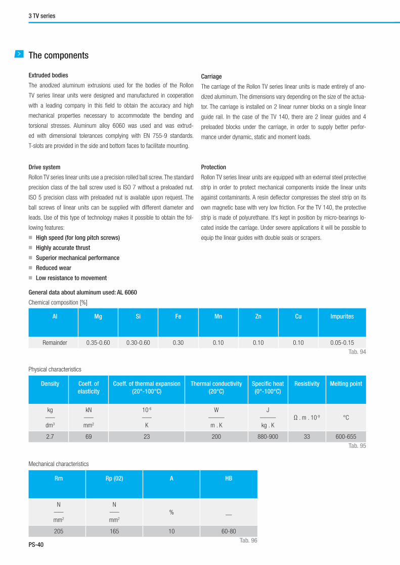
PS-40
3 TV series
The components
Extruded bodies
The anodized aluminum extrusions used for the bodies of the Rollon
TV series linear units were designed and manufactured in cooperation
with a leading company in this fi eld to obtain the accuracy and high
mechanical properties necessary to accommodate the bending and
torsional stresses. Aluminum alloy 6060 was used and was extrud-
ed with dimensional tolerances complying with EN 755-9 standards.
T-slots are provided in the side and bottom faces to facilitate mounting.
Drive system
Rollon TV series linear units use a precision rolled ball screw. The standard
precision class of the ball screw used is ISO 7 without a preloaded nut.
ISO 5 precision class with preloaded nut is available upon request. The
ball screws of linear units can be supplied with different diameter and
leads. Use of this type of technology makes it possible to obtain the fol-
lowing features:
■ High speed (for long pitch screws)
■ Highly accurate thrust
■ Superior mechanical performance
■ Reduced wear
■ Low resistance to movement
Carriage
The carriage of the Rollon TV series linear units is made entirely of ano-
dized aluminum. The dimensions vary depending on the size of the actua-
tor. The carriage is installed on 2 linear runner blocks on a single linear
guide rail. In the case of the TV 140, there are 2 linear guides and 4
preloaded blocks under the carriage, in order to supply better perfor-
mance under dynamic, static and moment loads.
Protection
Rollon TV series linear units are equipped with an external steel protective
strip in order to protect mechanical components inside the linear units
against contaminants. A resin defl ector compresses the steel strip on its
own magnetic base with very low friction. For the TV 140, the protective
strip is made of polyurethane. It's kept in position by micro-bearings lo-
cated inside the carriage. Under severe applications it will be possible to
equip the linear guides with double seals or scrapers.
General data about aluminum used: AL 6060
Chemical composition [%]
Physical characteristics
Mechanical characteristics
AI Mg Si Fe Mn Zn Cu Impurites
Remainder 0.35-0.60 0.30-0.60 0.30 0.10 0.10 0.10 0.05-0.15
Density Coeff. of
elasticity
Coeff. of thermal expansion
(20°-100°C)
Thermal conductivity
(20°C)
Specifi c heat
(0°-100°C)
Resistivity Melting point
kg___
dm3
kN___
mm2
10-6
___
K
W_____
m . K
J_____
kg . K
Ω . m . 10-9 °C
2.7 69 23 200 880-900 33 600-655
Rm Rp (02) A HB
N___
mm2
N___
mm2
% __
205 165 10 60-80
Tab. 94
Tab. 95
Tab. 96

PS-41
Precision System
PS
TV 60
TV 60 Dimensions
Type
TV 60
Max. useful stroke length [mm] 2000
Max. speed [m/s] See page PS-46
Basement length LM [mm] LT - 58
Total length LT [mm] Stroke + 360
Zero travel weight [kg] 4.6
Weight for 100 mm useful stroke [kg] 0.65
Technical data
Tab. 97
Type Fy
[N]
Fz
[N]
Mx
[Nm]
My
[Nm]
Mz
[Nm]
Stat. Dyn. Stat. Dyn. Stat. Dyn. Stat. Dyn. Stat. Dyn.
TV 60 21294 11664 25350 13255 169 88 1483 775 1246 682
Type Fx
[N]
Screw Stat. Dyn.
TV 60
16-05 16100 12300
16-10 12300 9600
16-16 12000 9300
TV 60 - Load capacity
TV 60 - Load capacity FX
See verifi cation under static load and lifetime on page SL-2 and SL-3 Tab. 101
Type Ix
[107 mm4]
Iy
[107 mm4]
Ip
[107 mm4]
TV 60 0.064 0.081 0.145
Moments of inertia of the aluminum body
Fx
MzFz
Mx
FyMy
Tab. 99
Tab. 100
Fig. 42
Tab. 98
Type Max. positioning
precision [mm/300mm]
Max. repeatability
precision [mm]
ISO 5 ISO 7 ISO 5 ISO 7
TV 60 / 16-05 0.023 0.05 0.01 0.05
TV 60 / 16-10 0.023 0.05 0.01 0.05
TV 60 / 16-16 0.023 0.05 0.01 0.05
Ball screw precision
635
LM L
28 52,5 85
4X M4X8
11
2462833 STROKE 28 25
70
4385
30
65 4X M6X12
190
Ø10
h6
Ø38
h6
46 5 65
2618
405
6

PS-42
TV 80
TV 80 Dimensions
Type
TV 80
Max. useful stroke length [mm] 3000
Max. speed [m/s] See page PS-46
Basement length LM [mm] LT - 60
Total length LT [mm] Stroke + 460
Zero travel weight [kg] 7.8
Weight for 100 mm useful stroke [kg] 0.95
Technical data
Tab. 102
Type Fy
[N]
Fz
[N]
Mx
[Nm]
My
[Nm]
Mz
[Nm]
Stat. Dyn. Stat. Dyn. Stat. Dyn. Stat. Dyn. Stat. Dyn.
TV 80 29610 16344 35250 18573 320 169 1827 963 1535 847
Type Fx
[N]
Screw Stat. Dyn.
TV 8020-05 21500 14300
20-20 18800 13300
TV 80 - Load capacity
TV 80 - Load capacity FX
See verifi cation under static load and lifetime on page SL-2 and SL-3 Tab. 106
Type Ix
[107 mm4]
Iy
[107 mm4]
Ip
[107 mm4]
TV 80 0.106 0.152 0.258
Moments of inertia of the aluminum body
Fx
MzFz
Mx
FyMy
Tab. 104
Tab. 105
Fig. 43
Tab. 103
Type Max. positioning
precision [mm/300mm]
Max. repeatability
precision [mm]
ISO 5 ISO 7 ISO 5 ISO 7
TV 80 / 20-05 0.023 0.05 0.01 0.05
TV 80 / 20-20 0.023 0.05 0.01 0.05
Ball screw precision
3 TV series
32,5 65 65 65260
8X M6X11
60 L M L
636
42 87,5 85
7
4X M4X83442840 2028 STROKE
22
44
LUBRICATION HOLE
70
5410
0
30
80 4X M6X12
Ø 1
2 h6Ø
46
h6
55
8
12
7
1825
20

PS-43
Precision System
PS
TV 110
TV 110 Dimensions
Type
TV 110
Max. useful stroke length [mm] 3000
Max. speed [m/s] See page PS-46
Basement length LM [mm] LT - 75
Total length LT [mm] Stroke + 525
Zero travel weight [kg] 16.8
Weight for 100 mm useful stroke [kg] 1.9
Technical data
Tab. 107
Type Fy
[N]
Fz
[N]
Mx
[Nm]
My
[Nm]
Mz
[Nm]
Stat. Dyn. Stat. Dyn. Stat. Dyn. Stat. Dyn. Stat. Dyn.
TV 110 45990 26262 54750 29843 572 312 3477 1895 2920 1668
Type Fx
[N]
Screw Stat. Dyn.
TV 110
32-05 40000 21600
32-10 58300 31700
32-32 34000 19500
TV 110 - Load capacity
TV 110 - Load capacity FX
See verifi cation under static load and lifetime on page SL-2 and SL-3 Tab. 111
Type Ix
[107 mm4]
Iy
[107 mm4]
Ip
[107 mm4]
TV 110 0.432 0.594 1.026
Moments of inertia of the aluminum body
Fx
MzFz
Mx
FyMy
Tab. 109
Tab. 110
Fig. 44
Tab. 108
Type Max. positioning
precision [mm/300mm]
Max. repeatability
precision [mm]
ISO 5 ISO 7 ISO 5 ISO 7
TV 110 / 32-05 0.023 0.05 0.01 0.05
TV 110 / 32-10 0.023 0.05 0.01 0.05
TV 110 / 32-32 0.023 0.05 0.01 0.05
Ball screw precision
85
42,5 75 75 75310
8X M8X18
LM L
1355
Ø 22
h6
Ø 85
f8
423942850 STROKE 2825
LUBRICATION HOLE
25
60,6
86
86
7312
9
110 4X M10X20
85 8
58
12
122560
4520
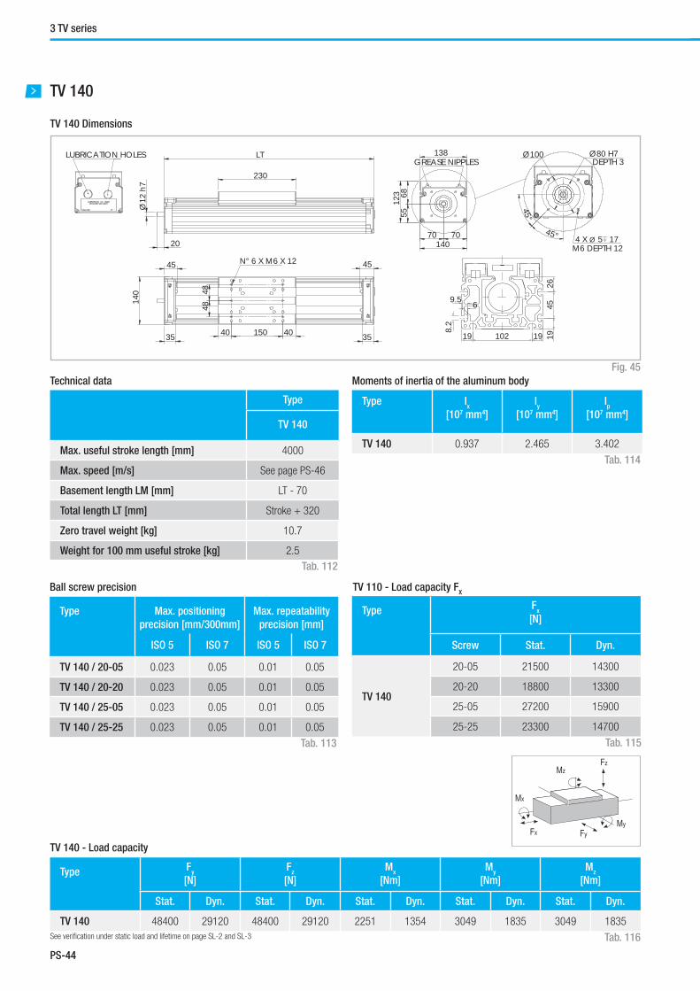
PS-44
TV 140
TV 140 Dimensions
Type
TV 140
Max. useful stroke length [mm] 4000
Max. speed [m/s] See page PS-46
Basement length LM [mm] LT - 70
Total length LT [mm] Stroke + 320
Zero travel weight [kg] 10.7
Weight for 100 mm useful stroke [kg] 2.5
Technical data
Tab. 112
Type Fy
[N]
Fz
[N]
Mx
[Nm]
My
[Nm]
Mz
[Nm]
Stat. Dyn. Stat. Dyn. Stat. Dyn. Stat. Dyn. Stat. Dyn.
TV 140 48400 29120 48400 29120 2251 1354 3049 1835 3049 1835
Type Fx
[N]
Screw Stat. Dyn.
TV 140
20-05 21500 14300
20-20 18800 13300
25-05 27200 15900
25-25 23300 14700
TV 140 - Load capacity
TV 110 - Load capacity FX
See verifi cation under static load and lifetime on page SL-2 and SL-3 Tab. 116
Type Ix
[107 mm4]
Iy
[107 mm4]
Ip
[107 mm4]
TV 140 0.937 2.465 3.402
Moments of inertia of the aluminum body
Fx
MzFz
Mx
FyMy
Tab. 114
Tab. 115
Fig. 45
Tab. 113
Type Max. positioning
precision [mm/300mm]
Max. repeatability
precision [mm]
ISO 5 ISO 7 ISO 5 ISO 7
TV 140 / 20-05 0.023 0.05 0.01 0.05
TV 140 / 20-20 0.023 0.05 0.01 0.05
TV 140 / 25-05 0.023 0.05 0.01 0.05
TV 140 / 25-25 0.023 0.05 0.01 0.05
Ball screw precision
3 TV series
Ø12
h7
20
LT
230
LUBRICATION HOLES 138
123
5
5
68
70 70 140
GREASE NIPPLES
35 35
140
40 150 40
48
48
N° 6 X M6 X 12 45 45
Ø100 Ø80 H7DEPTH 3
45°
45° 4 X Ø 5 17 M6 DEPTH 12
1910219
9.5 6
1945
26
8.2

PS-45
Precision System
PS
Tab. 118
Lubrication
TV 60, TV 80, TV 110 linear units
Rollon TV-series linear units are equipped with ball bearing guides lubri-
cated with grease lithium soap based grade 2. Re-lubrication is required
every 3-6 months or approximately 100 km of linear travel. The appli-
cation environment and applied loads may infl uence the re-lubrication
periods.
TV 140 linear units
SP Linear units are equipped with self lubricating linear ball guides.
The ball bearing carriages of the SP versions are also fi tted with a
retention cage that eliminates "steel-steel" contact between adjacent
■ Insert the tip of the oil can in the specifi c grease nipples:
A - Linear block - B - Ball screw nut
■ Type of lubricant: Lithium soap grease of class NLGI 2.
■ For specially stressed applications or diffi cult enviromental conditions,
lubrication should be carried out more frequently.
Apply to Rollon for futher advice.
Quantity of lubricant necessary for block re-lubrication:
Type Quantity [ g ] of grease
for each nipple
TV 60 1.4
TV 80 2.6
TV 110 5.0
TV 140 1.3
Fig. 46
revolving parts and prevents misalignment of these in the circuits.
Special lubrication reservoirs are mounted on the front plates of the linear
blocks which continuously provide the necessary amount of grease to the
ball raceways under load. These lubrication reservoirs also considerably re-
duce the frequency of lubrication of the module. This system guarantees a
long interval between maintenances: SP version: every 5000 km or 1 year
of use, based on the value reached fi rst. If a longer service life is required
or in case of high dynamic or high loaded applications please contact our
offi ces for further verifi cation.
Turns Lead
5mm
Lead
10mm
Lead
16mm
Lead
20mm
Lead
25mm
Lead
32mm
50 · 106 250 km 500 km 800 km 1000 km 1250 km 1600 km
Type Quantity [ g ] for grease nipple
16-05 0.6
16-10 0.8
16-16 1.0
20-05 0.9
20-20 1.7
25-05 1.4
25-25 2.4
32-05 2.3
32-10 2.8
32-32 3.7
Ball screws
The ball screw nuts of Rollon TV-series linear units must be re-lubricated
every 50 ·106 revolutions. Therefore, using the following conversion table,
according to the pitch of the screw, the units must be re-lubricated when
the linear travel distance (in km) indicated above has been reached.
Grease Nipples position
The position of grease nipples for the linear blocks and for the ball screw
nuts are indicated in the specifi c drawings of each product.
Tab. 117 Tab. 119
N° turns / linear path comparison table
Amount of lubricant recommended for ball screw nut re-lubrication
A
A
B

PS-46
Critical speed
Calculation factors
The maximum linear speed of Rollon TV series linear units depends on the
critical speed of the screw (based on its diameter and length) and on the
max. permissible speed of the ball screw nut used. The limit speed for
Rollon TV series units can be verifi ed using the following formula:
fV
max = ——— [m/s]
ln2
Screw diameter and lead Calculation factor (f) Critical length of the screw
( ln )
16-05 1.63 ·105
LT - Culn = LT - ( ———— ) 2
16-10 3.25 ·105
16-16 5.20 ·105
20-05 2.13 ·105
20-20 8.42 ·105
25-05 2.76 ·105
25-25 13.48 ·105
32-05 3.58 ·105
32-10 7.03 ·105
32-32 22.50 ·105
Screw diameter and leadMax. linear speed
of the ball screw nut
[m/s]
16-05 0.5
16-10 1.0
16-16 1.6
20-05 0.5
20-20 2.0
25-05 0.5
25-25 2.5
32-05 0.4
32-10 0.8
32-32 2.5
The maximum linear speed, which depends on the ball screw nut, is indicated directly in the table below.
Tab. 121
Tab. 120
Tab. 122
LT = Total length
Cu = Useful stroke
3 TV series
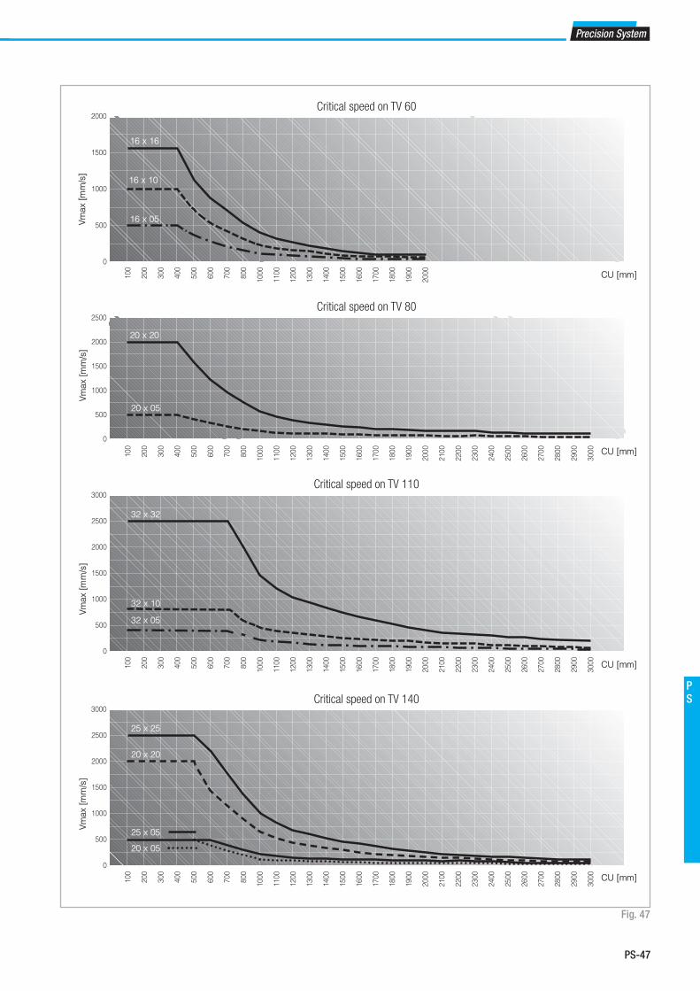
PS-47
Precision System
PS
Fig. 47
100
200
300
400
500
600
700
800
1000
1100
1200
1300
1400
1500
1600
1700
1800
1900
2000
100
200
300
400
500
600
700
800
1000
1100
1200
1300
1400
1500
1600
1700
1800
1900
2000
2100
2200
2300
2400
2500
2600
2700
2800
2900
3000
2000
1500
1000
500
0
Vm
ax [
mm
/s]
CU [mm]
CU [mm]
CU [mm]
CU [mm]
2500
2000
1500
1000
500
0
100
200
300
400
500
600
700
800
1000
1100
1200
1300
1400
1500
1600
1700
1800
1900
2000
2100
2200
2300
2400
2500
2600
2700
2800
2900
3000
3000
2500
2000
1500
1000
500
0
100
200
300
400
500
600
700
800
1000
1100
1200
1300
1400
1500
1600
1700
1800
1900
2000
2100
2200
2300
2400
2500
2600
2700
2800
2900
3000
3000
2500
2000
1500
1000
500
0
16 x 16
16 x 10
16 x 05
20 x 20
20 x 05
32 x 32
32 x 10
32 x 05
25 x 25
20 x 20
25 x 05
20 x 05
Critical speed on TV 60
Critical speed on TV 140
Critical speed on TV 110
Critical speed on TV 80
Vm
ax [
mm
/s]
Vm
ax [
mm
/s]
Vm
ax [
mm
/s]

PS-48
Accessories
Fixing by brackets
The linear motion systems used for the Rollon TV series linear units ena-
bles them to support loads in any direction. They can therefore be installed
in any position. To install the units, we recommend the use of the dedi-
cated slots in the extruded bodies as shown below.
Fixing bracket
Anodized aluminum block for fi xing the linear units through the side slots
of the body.
T-nuts
Steel nuts to be used in the slots of the body.
TypeA
[mm]
TV 60 77
TV 80 94
TV 110 130
TV 140 154
Type C H L D Code
Rollon
TV 60 16 19.5 35 M5 1002358
TV 80 16 20 50 M6 1002359
TV 110 31 27 100 M10 1002360
TV 140 16 22 50 M6 1001491
Slot M5 M6 M8
5 6001038 - -
8 6001044 6001045
8.2 - 1000043 -
Tab. 123
Tab. 124
Tab. 125
Warning: Do not secure the linear units by means of the T-slots in the
Drive head or Idle head at either end of the actuator.
Dimensions / Unit [mm]
Code Rollon
Fig. 48
Fig. 49
Fig. 50
3 TV series
L L/2
H
C
D
A

PS-49
Precision System
PS
Fig. 51
Tab. 126
Proximity switch holder
Red anodized aluminum block, equipped with T-nuts for fi xing into the
body slots.
Sensor dog
Zinc-plated steel plate, mounted on the carriage and used for the proxim-
ity switch operation.
B4 B5 L4 L5 H4 H5 Sensor Proximity
holder set
Sensor
dog
TV 60 20 20 105 40 10 32 Ø12 G000849 G000581
TV 80 20 20 105 40 10 32 Ø12 G000849 G000581
TV 110 20 20 105 40 10 32 Ø12 G000850 G000581
TV 140 21 20 50 40 20 32 Ø12 G000209 G000269
Proximity
Unit [mm]
L5L4B5
B4H4H5
SENSOR DOG
PROXIMITYSWITCH HOLDER
SENSOR DOG
PROXIMITY SWITCH HOLDER

PS-50
Identifi cation code for the TV linear units
V 06
06=60
08=80
11=110
14=140
1605
16-05
16-10
16-16
20-05
20-20
25-05
25-25
32-05
32-10
32-32
5P
5P=ISO 5
7N=ISO 7
0800 1A
L=total length of th unit
Type see from pg. PS-39 to pg. PS-42, tab. 100, 105, 110, 115
B/S diameter and lead
Size see from pg. PS-39 to pg. PS-42
Linear unit series TV see pg. PS-37
Ordering key
Ordering key
In order to create identifi cation codes for Actuator Line, you can visit: http://confi gureactuator.rollon.com

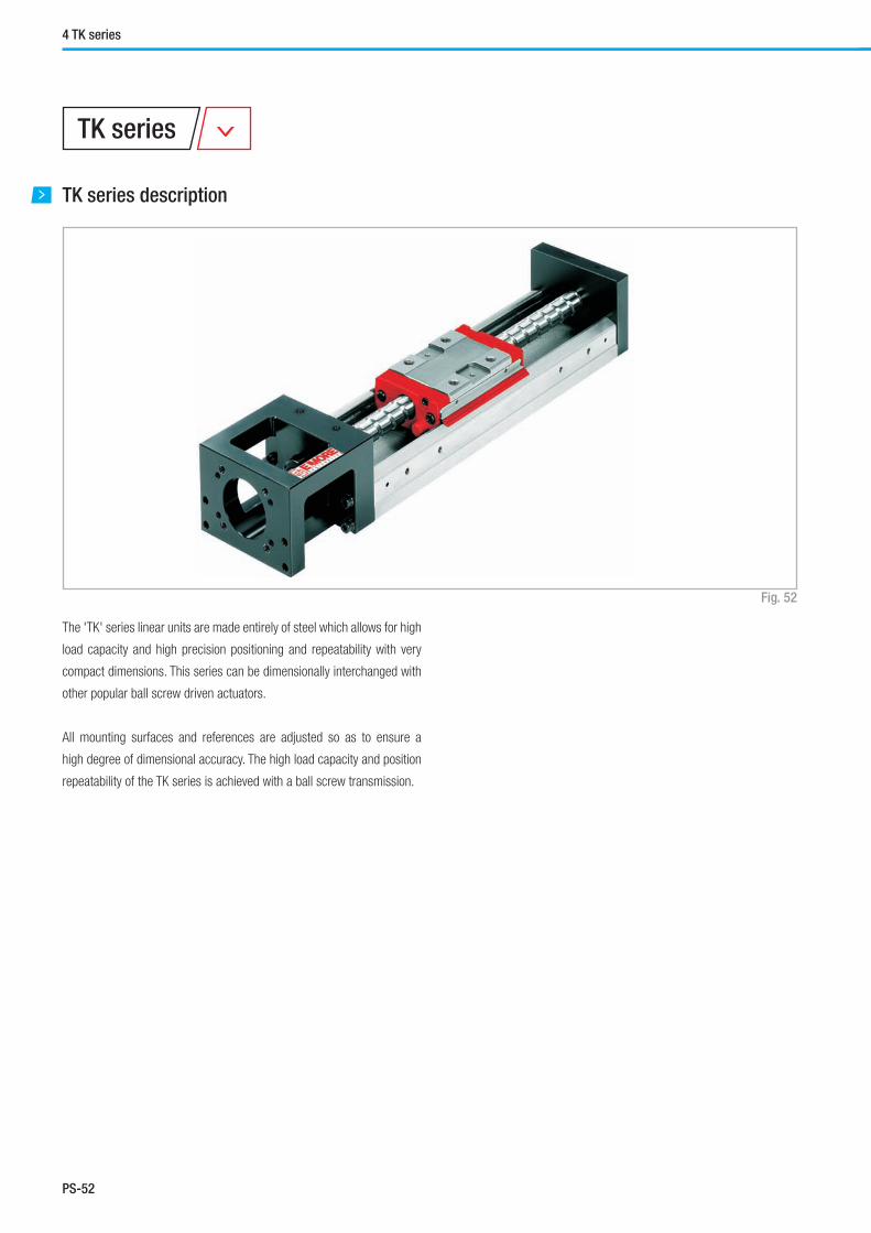
PS-52
TK series description
TK series
Fig. 52
The 'TK' series linear units are made entirely of steel which allows for high
load capacity and high precision positioning and repeatability with very
compact dimensions. This series can be dimensionally interchanged with
other popular ball screw driven actuators.
All mounting surfaces and references are adjusted so as to ensure a
high degree of dimensional accuracy. The high load capacity and position
repeatability of the TK series is achieved with a ball screw transmission.
4 TK series

PS-53
Precision System
PS
The components
The steel profi le
The profi le of Rollon TK series linear unit is made by a hot drawn bearing
grade steel. The ball grooves are located on the inner side of the U shaped
steel profi le. These grooves are hardened and grinded in order to obtain
a high accuracy running parallelism similar to a ball bearing linear guide.
Carriage
The carriage of Rollon TK series linear units is made from the same steel
alloy as the profi le. The carriage combines the functions of both a linear
bearing as well as a ball nut in one unit. The body is hardened and ground
on the ball grooves of the nut and on the ball grooves of the linear block.
Protection
Rollon TK series linear units are equipped with front and lateral seals in
order to protect the carriage and the nut during operation of the guide
on the ball screw. High temperature resistant bellows are mounted upon
request for Rollon TK series linear units, except on the TK 40.
Drive system
The standard precision class is ISO 5 with a light preload. ISO 7 is avail-
able with a controlled clearance upon request. The ball screws of the
linear units can be supplied with different diameter and leads. Use of this
technology makes it possible to obtain the following features:
■ High stiffness and compact system
■ High load capacity and thrust force
■ Superior mechanical performance
■ Reduced wear
■ Low resistance to movement

PS-54
TK 40
Fig. 53
TK 40 Dimensions
4 TK series
1.2
10
27
0.5
814.5
251249
0 4h
7
0 20
h7
G60
(N-1)X60
58
33
20
39.6
6
2.5
18 18
5
L2
L1
2XN - 03.4 06.5X3 DEPTH 4-M3X4.5 DEPTH
2X2-M2.6X4 DEPTH
2-M2.6X4 DEPTH
10
30°
30°Ø29
0.5
1329
.5
30
4-M3X6 DEPTH
1118
40
20
13 13.5
18
26

PS-55
Precision System
PS
Type Fx
[N]
Screw Stat. Dyn.
TK 40 08-01 1284 676
TK 40 - Load capacity FX
Technical data
Tab. 127
Tab. 129
TK 40 - Load capacity
See verifi cation under static load and lifetime on page SL-2 and SL-3 Tab. 130
Fx
MzFz
Mx
FyMy
Type
TK 40
Useful stroke 1 carriage CU1 [mm] 36 86 136
Useful stroke 2 carriages CU2 [mm] - 34 84
G Dimension [mm] 20 15 40
n Dimension [mm] 2 3 3
Max. speed [m/s] See page PS-60
Guide length L2 [mm] 100 150 200
Total length LT [mm] 159 209 259
Weight 1 carriage [Kg] 0.48 0.6 0.72
Weight 2 carriages [Kg] - 0.67 0.79
Type Fy
[N]
Fz
[N]
Mx
[Nm]
My
[Nm]
Mz
[Nm]
Stat. Dyn. Stat. Dyn. Stat. Dyn. Stat. Dyn. Stat. Dyn.
TK 40 1 carriage 6468 3920 6468 3920 81 - 33 - 33 -
TK 40 2 carriages 12976 7840 12976 7840 162 - 182 - 182 -
Tab. 128
Type Starting torque
[Nm]
Max. positioning
precision [mm/300mm]
Max. repeatability
precision [mm]
ISO 5 ISO 7 ISO 5 ISO 7 ISO 5 ISO 7
TK 40 / 08-01 0.012 0.008 0.02 - 0.003 0.01
Ball screw precision

PS-56
TK 60
Fig. 54
TK 60 Dimensions
4 TK series
Ø 2
8 h7
Ø 6
h7
915.5
18.5 30.559
G100
(N-1)X100
11
1.5
153060
15
33
2322
4230
45°
45°
30°
30°
0.5
44.5
Ø40
4-M4X8 DEPTH4-M3X8 DEPTH
59.6
6GKL2
L1
15305182
2XM-M2.6X4 DEPTH 4-M5X8 DEPTH2XN Ø5.5 TROUGH Ø9.5X4.7DEPTH
2-M2.6X3 DEPTH
30 30
53
52
5266
414 - M6 - DEPTH 18MM

PS-57
Precision System
PS
Type
TK 60
Useful stroke 1 carriage CU1 [mm]Without bellows 60 110 210 310 410 510
With bellows 45 77 151 230 300 376
Useful stroke 2 carriages CU2 [mm]Without bellows - - 135 235 335 435
With bellows - - 93 165 241 317
G dimension 25 50 50 50 50 50
K dimension 100 100 200 100 200 100
n dimension [mm] 2 2 3 4 5 6
m dimension 2 3 2 4 3 6
Max. speed [m/s] See page PS-60
Guide length L2 [mm] 150 200 300 400 500 600
Total length LT [mm] 220 270 370 470 570 670
Weight 1 carriage [Kg] 1.5 1.8 2.4 3 3.6 4.2
Weight 2 carriages [Kg] - - 2.7 3.3 3.9 4.6
Technical data
Tab. 131
Type Fx
[N]
Screw Stat. Dyn.
TK 6012-05 5625 3377
12-10 3234 2107
TK 60 - Load capacity FX
Tab. 133
TK 60 - Load capacity
See verifi cation under static load and lifetime on page SL-2 and SL-3 Tab. 134
Fx
MzFz
Mx
FyMy
Type Fy
[N]
Fz
[N]
Mx
[Nm]
My
[Nm]
Mz
[Nm]
Stat. Dyn. Stat. Dyn. Stat. Dyn. Stat. Dyn. Stat. Dyn.
TK 60 1 carriage 21462 13230 21462 13230 419 - 152 - 152 -
TK 60 2 carriages 42924 26460 42924 26460 838 - 348 - 348 -
Tab. 132
Type Starting torque
[Nm]
Max. positioning
precision [mm/300mm]
Max. repeatability
precision [mm]
ISO 5 ISO 7 ISO 5 ISO 7 ISO 5 ISO 7
TK 60 / 12-05 0.15 0.07 0.02 - 0.003 0.01
TK 60 / 12-10 0.15 0.07 0.025 - 0.003 0.01
Ball screw precision

PS-58
4 TK series
TK 80
Fig. 55
TK 80 Dimensions
Ø 5
0+0.0
5-0
Ø 4
6Ø 8
h7
3.5
182823
5087
70100(N-1)X200L2
L1
13
4660
46
1930 32
204686
85
30°
45°
30°45°
32
131
63
Ø70
Ø60
4-M5X10 DEPTH4-M4X8 DEPTH
85
7.5H200
(M-1)X200
154675116
4646
2XN- Ø6.6 Ø11X6 DEPTH4-M6X12 DEPTH
2-M2.6X4 DEPTH2XM-M2.6X4 DEPTH
76
76
60
7090
4 - M8 - DEPTH 28MM

PS-59
Precision System
PS
Type
TK 80
Useful stroke 1 carriage CU1 [mm]Without bellows 210 310 410 510 610 810
With bellows 174 248 327 410 491 654
Useful stroke 2 carriages CU2 [mm]Without bellows 100 200 300 400 500 700
With bellows 84 158 237 319 399 561
H dimension 70 20 70 20 70 70
n dimension [mm] 3 4 5 6 7 9
m dimension 2 3 3 4 4 5
Max. speed [m/s] See page PS-60
Guide length L2 [mm] 340 440 540 640 740 940
Total length LT [mm] 440 540 640 740 840 1040
Weight 1 carriage [Kg] 5.7 6.9 8 9.2 10.4 11.6
Weight 2 carriages [Kg] 6.5 7.7 8.8 10 11.2 12.4
Type Fx
[N]
Screw Stat. Dyn.
TK 8015-10 11387 6429
15-20 6889 4175
TK 80 - Load capacity FX
Technical data
Tab. 135
Tab. 137
TK 80 - Load capacity
See verifi cation under static load and lifetime on page SL-2 and SL-3 Tab. 138
Fx
MzFz
Mx
FyMy
Type Fy
[N]
Fz
[N]
Mx
[Nm]
My
[Nm]
Mz
[Nm]
Stat. Dyn. Stat. Dyn. Stat. Dyn. Stat. Dyn. Stat. Dyn.
TK 80 1 carriage 50764 31458 50764 31458 1507 - 622 - 622 -
TK 80 2 carriages 101348 62916 101348 62916 3014 - 3050 - 3050 -
Tab. 136
Type Starting torque
[Nm]
Max. positioning
precision [mm/300mm]
Max. repeatability
precision [mm]
ISO 5 ISO 7 ISO 5 ISO 7 ISO 5 ISO 7
TK 80 / 15-10 0.17 0.1 0.03 - 0.003 0.01
TK 80 / 15-20 0.17 0.1 0.03 - 0.003 0.01
Ball screw precision

PS-60
Critical speed
TypeBall screw lead
[mm]
Rail length
[mm]
Maximun speed
[m/sec]
ISO 5 ISO 7
TK 40/08-01 1
100 0.190 0.190
150 0.190 0.190
200 0.190 0.190
TK 60/12-05 5
150 0.550 0.390
200 0.550 0.390
300 0.550 0.390
400 0.550 0.390
500 0.550 0.390
600 0.340 0.340
TK 60/12-10 10
150 1.100 0.790
200 1.100 0.790
300 1.100 0.790
400 1.100 0.790
500 1.100 0.790
600 0.670 0.670
TK 80/15-10 10
340 0.740 0.520
440 0.740 0.520
540 0.740 0.520
640 0.740 0.520
740 0.740 0.520
940 n.a. 0.430
TK 80/15-20 20
340 1.480 1.050
440 1.480 1.050
540 1.480 1.050
640 1.480 1.050
740 1.480 1.050
940 1.220 0.870
Tab. 139
4 TK series

PS-61
Precision System
PS
Identifi cation code for the TK linear units
K 04
04=40
06=60
08=80
0801
08-01
12-05
12-10
15-10
15-20
5P
5P=ISO 5
7N=ISO 7
0800 1A
1A = 1 carriage
2A = 2 carriages
Carriage confi guration code
L=total length of th unit
Type see from pg. PS-52 to pg. PS-56, tab. 131, 135, 139
B/S diameter and lead
Size see from pg. PS-52 to pg. PS-56
Linear unit series TK see pg. PS-50
Ordering key
In order to create identifi cation codes for Actuator Line, you can visit: http://confi gureactuator.rollon.com

PS-62
Ordering key
System with 2 horizontal axes Three-axes system
System with 2 horizontal axes
A
B
A - Direct fastening of the Y-axis on the X-axis ("base unit on carriage"
assembly) using screws without intermediate brackets.
C - Fastening of the Y-axis on the X-axis (“base unit on carriage“
assembly) using 90° brackets.
Fastening of the Z-axis on the Y-axis (“carriage on carriage" assem-
bly) using a “cross“ plate.
B - Fastening of the Y-axis on the X-axis ("carriage on carriage" assem-
bly) using a "cross" plate.
Multiaxis systems
AA
BB
Rollon Precision System series linear units have been specifi cally designed
to be modular and therefore to permit fast, trouble-free setup of multi-axis
systems. Rollon can provide all the connection elements necessary for com-
bining the various sizes and lengths of Precision System series linear units.
Connection plates are available only upon request
C
Three-axes system
D
D - Fastening of the Y-axis on the X-axis (“base unit on carriage
assembly) using 90° brackets.

PS-63
Precision System
PS
Notes

Static load
In the static load test, the radial load rating Fy, the axial load rating F
z,
and the moments Mx, M
y und M
z indicate the maximum allowed load val-
ues. Higher loads will impair the running characteristics. To check the
static load, a safety factor S0 is used, which accounts for the special
conditions of the application defi ned in more detail in the table below:
Safety factor S0
Belt safety factor referred to the dynamic FX
Fig. 1
No shocks or vibrations, smooth and low-frequency change in direction
High mounting accuracy, no elastic deformations, clean environment2 - 3
Normal assembly conditions 3 - 5
Shocks and vibrations, high-frequency changes in direction, substantial elastic deformations 5 - 7
Fig. 2
Fig. 3
The above formulae only apply to a one load case. If one or more of the
forces described are acting simultaneously, the following calculation must
be carried out:
The ratio of the actual to the maximum allowed load must not be higher
than the reciprocal value of the assumed safety factor S0.
Pfy
1
Fy S
0
≤P
fz 1
Fz S
0
≤M
1 1
Mx S
0
≤M
2 1
My S
0
≤M
3 1
Mz S
0
≤
Pfy = acting load (y direction) (N)
Fy = static load rating (y direction) (N)
Pfz = acting load (z direction) (N)
Fz = static load rating (z direction) (N)
M1, M
2, M
3 = external moments ( Nm)
Mx, M
y, M
z = maximum allowed moments in the different load directions (Nm)
Pfy
Pfz M
1 M
2 M
3
Fy F
z M
x M
y M
z
+ + + + ≤1
S0
The safety factor S0 can be at the lower limit given if the acting forces can
be determined with suffi cient accuracy. If shocks and vibrations act on
the system, the higher value should be selected. In dynamic applications,
higher safeties are required. For further information, please contact our
Application Engineering Department.
Static load and service life Plus-Clean Room-Smart-Eco-Precision
Impact and
vibrations
Speed /
acceleration
Orietation Safety
Factor
No impacts
and/or vibrationsLow
horizontal 1.4
vertical 1.8
Light impacts
and/or vibrationsMedium
horizontal 1.7
vertical 2.2
Strong impacts
and/or vibrationsHigh
horizontal 2.2
vertical 3
Tab. 1
Static load and service life Plus-Clean Room-Smart-Eco-Precision
SL-2

For SP types
For CI and CE types
Peq
= Pfy + P
fz + ( ––– + ––– + ––– ) · F
y
M1
Mx
M2
My
M3
Mz
Peq
= Pfy + ( ––– + ––– + ––– + ––– ) · F
y
Pfz
Fz
M1
Mx
M2
My
M3
Mz
Fig. 5
Fig. 6
The external constants are assumed to be constant over time. Short-term
loads that do not exceed the maximum load ratings have no relevant effect
on the service life and can therefore be neglected in the calculation.
The effective equivalent load Peq
is the sum of the forces and moments
acting simultaneously on a slider. If these different load components are
known, P is obtained from the following equation:
f i
no shocks or vibrations, smooth and low-frequency changes in direction; (α < 5m/s2)
clean operating conditions; low speeds (<1 m/s) 1.5 - 2
Slight vibrations; medium speeds;
(1-2 m/s) and medium-high frequency of the changes in direction (5m/s2 < α < 10 m/s2)2 - 3
Shocks and vibrations; high speeds (>2 m/s) and high-frequency changes in direction; (α > 10m/s2)
high contamination, very short stroke> 3
Tab. 2
Service life
Calculation of the service life
The dynamic load rating C is a conventional quantity used for calculating
the service life. This load corresponds to a nominal service life of 100 km.
Fig. 4
Lkm
= 100 km · ( ––– · ––– )3C
P
1
fi
Lkm
= theoretical service life (km)
C = dynamic load rating (N)
P = acting equivalent load (N)
fi = service factor (see tab. 2)
The calculated service life, dynamic load rating and equivalent load are
linked by the following formula:
Service factor fi
SL-3

Static load and service life Uniline
Static loadIn the static load test, the radial load rating C
0rad, the axial load rating
C0ax
, and the moments Mx, M
y und M
z indicate the maximum allowed
load values. Higher loads will impair the running characteristics. To check
the static load, a safety factor S0 is used, which accounts for the special
conditions of the application defi ned in more detail in the table below:
Safety factor S0
Fig. 7
No shocks or vibrations, smooth and low-frequency change in direction
High mounting accuracy, no elastic deformations, clean environment1 - 1.5
Normal assembly conditions 1.5 - 2
Shocks and vibrations, high-frequency changes in direction, substantial elastic deformations 2 - 3.5
Fig. 8
Fig. 9
The above formulae apply to a one load case. If one or more of the forces
described are acting simultaneously, the following test must be carried
out:
The ratio of the actual to the maximum allowed load must not be higher
than the reciprocal value of the assumed safety factor S0.
P0rad
1
C0rad
S0
≤P
0ax 1
C0ax
S0
≤M
1 1
Mx S
0
≤M
2 1
My S
0
≤M
3 1
Mz S
0
≤
P0rad
= acting radial load (N)
C0rad
= allowed radial load (N)
P0ax
= acting axial load (N)
C0ax
= allowed axial load (N)
M1, M
2, M
3 = external moments ( Nm)
Mx, M
y, M
z = maximum allowed moments
in the different load directions (Nm)
P0rad
P0ax
M1 M
2 M
3
C0rad
C0ax
Mx M
y M
z
+ + + + ≤1
S0
The safety factor S0 can be at the lower limit given if the acting forces can
be determined with suffi cient accuracy. If shocks and vibrations act on
the system, the higher value should be selected. In dynamic applications,
higher safeties are required. For further information, please contact our
Application Engineering Department.
Static load and service life Uniline
SL-4

Calculation formulaeMoments M
y and M
z for linear units with long slider plate
The allowed loads for the moments My and M
z depend on the length of the
slider plate. The allowed moments Mzn and M
yn for each slider plate length
are calculated by the following formulae:
Fig. 10
Mzn = ( 1+ ––––––– ) · M
z min
Sn - S
min
K
Mzn = allowed moment (Nm)
Mz min
= minimum values (Nm)
Myn = allowed moment (Nm)
My min
= minimum values (Nm)
Sn = length of the slider plate (mm)
Smin
= minimum length of the slider plate (mm)
ΔS = factor of the change in slider length
K
= constant
Type My min
[Nm]
Mz min
[Nm]
Smin
[mm]
ΔS K
A40L 22 61 240
10
74
A55L 82 239 310 110
A75L 287 852 440 155
C55L 213 39 310 130
C75L 674 116 440 155
E55L 165 239 310 110
E75L 575 852 440 155
ED75L (Mz) 1174 852 440 155
ED75L (My) 1174 852 440 270
Tab. 3
Myn = ( 1+ ––––––– ) · M
y min
Sn - S
min
K
Sn = S
min + n · ΔS
SL-5

Static load and service life Uniline
Moments My and M
z for linear units with two slider plates
The allowed loads for the moments My and M
z are related to the value of
the distance between the centers of the sliders. The allowed moments Myn
and Mzn for each distance between the centers of the sliders are calculat-
ed by the following formulae:
Fig. 11
Mz = ( ––– ) · M
z min
Ln
Lmin
My = allowed moment (Nm)
Mz = allowed moment (Nm)
My min
= minimum values (Nm)
Mz min
= minimum values (Nm)
Ln = distance between the centers of the sliders (mm)
Lmin
= minimum value for the distance between the centers of the sliders (mm)
ΔL = factor of the change in slider length
My = ( ––– ) · M
y min
Ln
Lmin
Type My min
[Nm]
Mz min
[Nm]
Lmin
[mm]
ΔL
A40D 70 193 235 5
A55D 225 652 300 5
A75D 771 2288 416 8
A100D 2851 4950 396 50
C55D 492 90 300 5
C75D 1809 312 416 8
E55D 450 652 300 5
E75D 1543 2288 416 8
ED75D 3619 2288 416 8
Ln = L
min + n · ΔL
The effective equivalent load P is the sum of the forces and moments
acting simultaneously on a slider. If these different load components are
known, P is obtained from the following equation:
Service life
Calculation of the service life
The dynamic load rating C is a conventional quantity used for calculating
the service life. This load corresponds to a nominal service life of 100 km.
The corresponding values for each liner unit are listed in Table 45 shown
Fig. 12
Lkm
= 100 km · ( ––– · ––– · fh )3
C
P
fc
fi
Lkm
= theoretical service life (km)
C = dynamic load rating (N)
P = acting equivalent load (N)
fi = service factor (see tab. 5)
fC = contact factor (see tab. 6)
fh = stroke factor (see fi g. 13)
below. The calculated service life, dynamic load rating and equivalent load
are linked by the following formula:
Tab. 4
SL-6

P = Pr + ( ––– + ––– + ––– + ––– ) · C
0rad
Pa
C0ax
M1
Mx
M2
My
M3
Mz
Fig. 13
The external constants are assumed to be constant over time. Short-term
loads that do not exceed the maximum load ratings have no relevant effect
on the service life and can therefore be neglected in the calculation.
f i
No shocks or vibrations, smooth and low-frequency changes in direction; clean operating
conditions; low speeds (<1 m/s)1 - 1.5
Slight vibrations; medium speeds;
(1-2,5 m/s) and medium-high frequency of the changes in direction1.5 - 2
Shocks and vibrations; high speeds (>2.5 m/s) and high-frequency changes in direction; high
contamination2 - 3.5
Tab. 5
Service factor fi
The stroke factor fh accounts for the higher stress on the raceways and
rollers when short strokes are carried out at the same total run distance.
The following diagram shows the corresponding values (for strokes above
1 m, fh remains 1):
Fig. 14
Stroke [m]
f h
fc
Standard slider 1
Long slider 0.8
Double slider 0.8
Tab. 6
Contact factor fc
Stroke factor fh
The torque Cm required at the drive head of the linear axis is calculated by
the following formula:
Determination of the motor torque
Fig. 15
Cm = C
v + ( F · ––– )
Dp
2
Cm = torque of the motor (Nm)
Cv = starting torque (Nm)
F = force acting on the toothed belt (N)
Dp
= pitch diameter of pulley (m)
SL-7

Notes
SL-8
Notes

General data: Date: ................................................ Inquiry N°: .............................................................................
Address: ................................................................................................................................................... Contact: ....................................................................................................................................................
Company: ............................................................................................................................................... Date: ...........................................................................................................................................................
Phone: ....................................................................................................................................................... Fax: ..............................................................................................................................................................
X axis Y axis Z axis
Useful stroke (Including safety overtravel) S [mm]
Load to be translated P [kg]
Location of Load in the X-Direction LxP [mm]
Y-Direction LyP [mm]
Z-Direction LzP [mm]
Additional force Direction (+/-) Fx (Fy, Fz) [N]
Position of force X-Direction Lx Fx (Fy, Fz) [mm]
Y-Direction Ly Fx (Fy, Fz) [mm]
Z-Direction Lz Fx (Fy, Fz) [mm]
Assembly position (Horizontal/Vertical/Transversal
Max. speed V [m/s]
Max. acceleration a [m/s2]
Positioning repeatability Δs [mm]
Required life L yrs
Technical data:
Attention: Please enclose drawing, sketches and sheet of the duty cycle
Horizontal position
Transversal position
Vertical position
Fx
Fz
Fy
+
++
-
--
L Px
L Pz
L PyP
Data sheet
SL-9


Via Trieste 26
I-20871 Vimercate (MB)
Phone: (+39) 039 62 59 1
www.rollon.it - [email protected]
ROLLON S.p.A. - ITALY
Rep. Offi ces:
117105, Moscow, Varshavskoye
shosse 17, building 1, offi ce 207.
Phone: +7 (495) 508-10-70
www.роллон.рфроллон.рф - [email protected]
ROLLON S.p.A. - RUSSIA
R. Joaquim Floriano, 397, 2o. andar
Itaim Bibi - 04534-011, São Paulo, BRASIL
Phone: +55 (11) 3198 3645
www.rollonbrasil.com.br - [email protected]
ROLLON - SOUTH AMERICA
Regional Manager:
1st fl oor, Regus Gem Business Centre, 26/1
Hosur Road, Bommanahalli, Bangalore 560068
Phone: (+91) 80 67027066
www.rollonindia.in - [email protected]
ROLLON India Pvt. Ltd. - INDIA
DistributorConsult the other ranges of products
All addresses of our global sales partners can also be found at www.rollon.com
Branches:
Bonner Strasse 317-319
D-40589 Düsseldorf
Phone: (+49) 211 95 747 0
www.rollon.de - [email protected]
ROLLON GmbH - GERMANY
Ringbaan Zuid 8
6905 DB Zevenaar
Phone: (+31) 316 581 999
www.rollon.nl - [email protected]
ROLLON B.V. - NETHERLANDS
101 Bilby Road. Suite B
Hackettstown, NJ 07840
Phone: (+1) 973 300 5492
www.rolloncorp.com - [email protected]
ROLLON Corporation - USA
Les Jardins d‘Eole, 2 allée des Séquoias
F-69760 Limonest
Phone: (+33) (0) 4 74 71 93 30
www.rollon.fr - [email protected]
ROLLON S.A.R.L. - FRANCE
51/F Raffl es City, 268 Xi Zang Middle Road,
200001 Shanghai (China)
Phone: (+86) 021 2312 7582
www.rollon.cn.com - [email protected]
ROLLON Ltd - CHINA
Changes and errors excepted. The text and images may be used only with our permission. ALT1_GC_EN_03/15
Rollon Branches & Rep. Offi ces
Distributors