active travel facilities design - city services...cycle facilities edition 1 revision 1 june 2007...
TRANSCRIPT
ACTIVE TRAVEL FACILITIES DESIGNMUNICIPAL INFRASTRUCTURE STANDARDS 05
Transport Canberra and City Services
APRIL 2019

ACT Government 2
Publication Number: MIS 05 Edition 1 Revision 0
Date of Effect:
Supersedes:
Design Standard for Urban Infrastructure Works Section 13 Pedestrian and Cycle Facilities Edition 1 Revision 1 June 2007 Design Standard for Urban Infrastructure Works Section 13 Pedestrian and Cycle Facilities Supplement 1 Treatments at Roundabouts, Share the Path sign May 2011
Endorsed By:
Approved By:
Document Information
Document Key Information
Document Title MIS 05 Active Travel Facilities Design
Next review date
Key words
AUS-SPEC Base Document Not applicable
Revision Register
Edition/ Revision Number Clause Number Description of Revision Authorised By Date
1/0
APRIL 2019
Karl Cloos - Director, Infrastructure Planning
Ken Marshall - Executive Branch Manager, Roads ACT

ACT Government 3
CONTENTS
1 DOCUMENTS FOR THE DESIGN OF ACTIVE TRAVEL FACILITIES ................ 9
1.1 ACT Active Travel Framework ....................................................................................... 9
2 GENERAL ............................................................................................... 9
2.1 Responsibilities ............................................................................................................. 9
2.1.1 Objective ................................................................................................................................ 9 2.2 Cross references .......................................................................................................... 10
2.2.1 Design standards – Key documents ..................................................................................... 10 2.2.2 ACT Legislation and major policy ......................................................................................... 10 2.2.3 ACT Active Travel Infrastructure guidelines ......................................................................... 11 2.2.4 Australian Standards ............................................................................................................ 11 2.2.5 Austroads guidelines ............................................................................................................ 11 2.2.6 ACT Design Guides................................................................................................................ 11 2.2.7 Use of other guidelines for supplementary guidance .......................................................... 11
2.3 Interpretations ............................................................................................................ 12
2.3.1 Abbreviations used in this document .................................................................................. 12 2.3.2 Glossary of terms used in this document ............................................................................. 13
3 PLANNING AND DESIGN POLICIES AND PRINCIPLES .............................. 18
3.1 ACT policies ................................................................................................................. 18
3.2 Active Travel Routes ................................................................................................... 20
3.3 ATR Planning process and definitions ......................................................................... 23
3.3.1 Preliminary design for facilities ............................................................................................ 24 3.3.2 Estate development – facilities in new or redeveloped areas ............................................. 25 3.3.3 Retrofit – Provision of facilities in established areas ........................................................... 27 3.3.4 Movement and Place ........................................................................................................... 28 3.3.5 Community engagement ...................................................................................................... 28
4 DESIGN OF FACILITIES FOR COMMUNITY ROUTES ................................. 29
4.1 Design principles for Community Routes ................................................................... 30
4.2 Design requirements and criteria for paths on Community Routes........................... 32
4.3 Separation of modes ................................................................................................... 38
4.4 Paths on Community Routes ...................................................................................... 40
4.4.1 Path design ........................................................................................................................... 41 4.4.2 Path gradient and disabled access ....................................................................................... 41 4.4.3 Path cross section ................................................................................................................. 42 4.4.4 Pavement materials ............................................................................................................. 42 4.4.5 Pavement design .................................................................................................................. 43 4.4.6 Proximity of trees, root barriers and moisture control barriers .......................................... 43 4.4.7 Vehicle access restriction to paths ....................................................................................... 44

ACT Government 4
4.4.8 Use of speed management devices on paths....................................................................... 45 4.4.9 Provision for paths at bridges and underpasses .................................................................. 46 4.4.10 Lighting of paths, bridges and underpasses ......................................................................... 46 4.4.11 Paths and floodways ............................................................................................................ 47 4.4.12 Traffic calming devices interaction with paths..................................................................... 47
4.5 Bicycle-only paths ....................................................................................................... 48
4.5.1 Use and selection of bicycle-only path types ....................................................................... 48 4.5.2 Design of bicycle-only paths ................................................................................................. 49 4.5.3 One-way paired bicycle-only paths ...................................................................................... 49 4.5.4 Two-way bicycle-only paths ................................................................................................. 50 4.5.5 Connections between one-way and two-way paths ............................................................ 51
4.6 Pedestrian-only paths ................................................................................................. 51
4.7 Community Route path junctions, terminations and street crossings ....................... 52
4.7.1 Path junctions ....................................................................................................................... 53 4.7.2 Path crossings and terminations with streets – general ...................................................... 53 4.7.3 Zebra crossings ..................................................................................................................... 54 4.7.4 Children’s crossings .............................................................................................................. 56 4.7.5 Path Priority crossings .......................................................................................................... 56 4.7.6 Signalised intersections, crossings and slip lane treatments ............................................... 57 4.7.7 Bicycle-only facilities at intersections - Signalised ............................................................... 58 4.7.8 Bicycle-only facilities at intersections - Unsignalised ........................................................... 59 4.7.9 Roundabouts ........................................................................................................................ 60 4.7.10 Refuge islands ...................................................................................................................... 61 4.7.11 Path crossings and terminations – uncontrolled ................................................................. 62 4.7.12 Continuous verges ................................................................................................................ 62 4.7.13 Driveway crossings across Community Routes .................................................................... 63 4.7.14 Path to roadway connections............................................................................................... 63
4.8 Facilities for Community Routes on streets ................................................................ 64
4.8.1 General ................................................................................................................................. 64 4.8.2 Active travel streets ............................................................................................................. 64 4.8.3 Shared zones ........................................................................................................................ 66 4.8.4 Shared space ........................................................................................................................ 66 4.8.5 Community Route facilities on-streets with narrow verge paths ........................................ 68 4.8.6 Community Route facilities on-streets without verge paths ............................................... 69
4.9 Integration with public transport – bus and light rail stops ....................................... 69
4.10 Directional signage for Community Routes ........................................................... 70
4.10.1 Planning for directional signs ............................................................................................... 70 4.10.2 Destinations and focal point names ..................................................................................... 71 4.10.3 Directional sign families ....................................................................................................... 72 4.10.4 Destination inclusion range .................................................................................................. 73 4.10.5 Destinations to be included on destination signage ............................................................ 74

ACT Government 5
4.10.6 Destination abbreviations .................................................................................................... 74 4.10.7 Directional signage design.................................................................................................... 75 4.10.8 Wayfinding on streets with mixed traffic ............................................................................. 81 4.10.9 Behavioural signage ............................................................................................................. 82 4.10.10 Minimum facility requirements to allow route signing ........................................................ 82 4.10.11 Directional sign locations and installation ........................................................................... 85 4.10.12 Directional sign distance measurement ............................................................................... 87
5 DESIGN OF FACILITIES FOR ACCESSIBLE PEDESTRIAN ROUTES ............... 88
5.1 General ........................................................................................................................ 88
5.2 Tactile ground surface indicators ............................................................................... 88
5.3 Indicator types ............................................................................................................ 89
5.4 Design of TGSI at crossing points ................................................................................ 90
5.5 Luminance contrast for TGSI ....................................................................................... 91
6 DESIGN OF FACILITIES FOR EQUESTRIAN ROUTES ................................. 92
6.1 General ........................................................................................................................ 92
6.2 Facilities for Equestrians ............................................................................................. 92
6.2.1 Equestrian trails ................................................................................................................... 92 6.2.2 Path crossings ....................................................................................................................... 94 6.2.3 Road crossings ...................................................................................................................... 94 6.2.4 Floodway crossings .............................................................................................................. 95 6.2.5 Directional signage for Equestrian Routes ........................................................................... 95 6.2.6 Activity and agistment areas ................................................................................................ 95
7 DESIGN OF FACILITIES FOR ON-ROAD CYCLING ROUTES ........................ 97
7.1 Facilities for On-Road Cycling Routes ......................................................................... 98
7.1.1 Bicycle lanes ......................................................................................................................... 99 7.1.2 Marked shoulders .............................................................................................................. 103 7.1.3 Termination of bicycle lanes and marked shoulders ......................................................... 103 7.1.4 Bicycle lanes adjacent to bus lanes .................................................................................... 103 7.1.5 Pavement marking of Main On-Road Cycling Routes ........................................................ 104 7.1.6 Raised retroreflective pavement markers ......................................................................... 104 7.1.7 Removal of redundant linemarking and RRPMs ................................................................ 104 7.1.8 Provision for cycling on-street at traffic calming devices .................................................. 104
7.2 Facilities for On-Road Cycling Routes at intersections ............................................. 105
7.2.1 General ............................................................................................................................... 105 7.2.2 Signalised intersection treatments .................................................................................... 106 7.2.3 Bicycle lanes at path crossings (signalised and unsignalised) ............................................ 107 7.2.4 Unsignalised intersection treatments ................................................................................ 107 7.2.5 Roundabouts ...................................................................................................................... 107 7.2.6 Roadway to path transitions .............................................................................................. 111

ACT Government 6
7.3 Coloured pavement treatment ................................................................................. 112
7.3.1 Warrant for use of coloured pavement treatment on Roadways ...................................... 112 7.4 On-Road Cycling Routes directional signage ............................................................ 114
7.4.1 General ............................................................................................................................... 114 7.5 Connection between On-Road Cycling Routes and Principal and Main Community Routes ................................................................................................................................. 114
7.5.1 Provision at structures ....................................................................................................... 114 7.5.2 Use of cycle rest rails .......................................................................................................... 115
8 DESIGN OF FACILITIES FOR RECREATIONAL ROUTES ............................ 116
8.1 General ...................................................................................................................... 116
8.2 Principal Recreational Trails ...................................................................................... 116
8.2.1 Design considerations ........................................................................................................ 116 8.2.2 Principal Recreational Trails signage .................................................................................. 116
8.3 Principal Cycle Racing/Training Routes ..................................................................... 117
8.3.1 Training route signage ........................................................................................................ 117 8.3.2 Cycle racing signage ........................................................................................................... 117
ACT Government 7
LIST OF TABLES
Table 5-1 Typical Active Travel Network facilities for Active Travel Routes ............................................ 22 Table 5-2 Scope of Section 4 – Facilities for Community Routes ............................................................. 29 Table 5-3 Key design principles of facilities for Community Routes (cycling use) ................................... 31 Table 5-4 Community Route facilities in Estate Development ................................................................. 32 Table 5-5 Minimum separation from traffic lanes for paths .................................................................... 39 Table 5-6 Path types ................................................................................................................................. 40 Table 5-7 Minor path gradients ................................................................................................................ 42 Table 5-8 Path speed-management devices ............................................................................................ 45 Table 5-9 Path junctions, terminations and crossing types ..................................................................... 52 Table 5-10 Priority crossing risk minimisation design requirements ......................................................... 55 Table 5-11 Recommended traffic management devices for Bicycle Boulevard installations .................... 65 Table 5-12 Community Routes destinations inclusion range ..................................................................... 73 Table 5-13 Community Route directional sign types ................................................................................. 75 Table 5-14 Risk assessment guidance prior to signing of routes ............................................................... 83 Table 5-15 Guidance on signage types required for various locations ...................................................... 86 Table 5-16 Design parameters for Accessible Pedestrian Routes .............................................................. 88 Table 5-17 Sample range of luminance contrast values for materials available in Canberra .................... 91 Table 5-18 Scope of Section 7 – Facilities for use on On-Road Cycling Routes .......................................... 97 Table 5-19 Types of bicycle facilities for On-Road Cycling Routes ............................................................. 98 Table 5-20 Bicycle lane widths on arterial roads and collectors in Retrofit ............................................. 101 Table 5-21 Provision of cycling treatments at roundabouts for On-Road Cycling Routes ....................... 110 Table 5-22 Warrant system for coloured pavement systems .................................................................. 113
ACT Government 8
LIST OF FIGURES
Figure 5-1 Implementation of ATN facilities in new development areas. ................................................. 26 Figure 5-2 Facility provision for Active Travel Routes referenced to road hierarchy. ............................... 35 Figure 5-3 Facilities for cyclists on CRs in Estate Development conceptual diagram. ............................... 36 Figure 5-4 Methods of separation ............................................................................................................. 38 Figure 5-5 One-way paired bicycle-only path ............................................................................................ 48 Figure 5-6 Two-way bicycle-only path at a minor street with continuous verge treatment .................... 50 Figure 5-7 Path Priority crossing of a local access street .......................................................................... 56 Figure 5-8 Two-way bicycle-only paths at a signalised intersection ......................................................... 58 Figure 5-9 Shared space providing vehicle access to a parking structure ................................................. 67 Figure 5-10 Bicycle lanes (above left – kerbside lane, above right – car-side lane) .................................... 99 Figure 5-11 Bicycle lane retrofitted to an arterial road ............................................................................. 100 Figure 5-12 The six design elements of a signalised intersection ............................................................. 105

ACT Government 9
1 DOCUMENTS FOR THE DESIGN OF ACTIVE TRAVEL FACILITIES
1.1 ACT Active Travel Framework The active travel routes are an ACT wide system of transport and recreational routes catering for walkers, cyclists and equestrian of all ages and abilities. This system is designed to facilitate the planning, design and ongoing maintenance of appropriate infrastructure that will encourage and provide for the widest possible range of active travel journeys.
The active travel network represents infrastructure that exists at any given time. The planning requirements for existing and future active travel routes and the development of the network are covered by the document Planning for Active Travel in the ACT referred to in detail in Section 3 of this document.
The remainder of this design standard (Sections 4 to 8) provides comprehensive guidance for the design and construction of infrastructure facilities which make up the ATN. Each section covers a different route type and the standard for facilities is governed by route hierarchy, land use and development contexts (refer Section 3)
A spatial overlay of the ATN and ATRs may establish where facilities in established areas do not meet the requirements of this Standard. All facilities are to meet the requirements of this Standard.
2 GENERAL 2.1 Responsibilities 2.1.1 Objective This Standard sets requirements related to the provision of infrastructure for active travel users including pedestrians, cyclists and equestrians which will:
> Encourage activity for transportation and recreational purposes; > Provide safe and convenient infrastructure which meets user needs; and, > Maintain a satisfactory level of service for all pedestrians, cyclists and equestrians including the aged
and people with disabilities and limited mobility.
This document covers the design of active travel infrastructure (pedestrian, cyclist and equestrian) associated with all ACT roads and urban open space areas. On-road bicycle facilities associated with arterial roads are covered in brief in the ACT Trunk Roads Infrastructure Standards and are referenced back to the detailed coverage provided in this Design Standard. Equestrian facilities design is also covered, including infrastructure design requirements for path/trail crossings and multi-use trails.
These Design Standards have been developed to assist road designers, engineers, landscape architects and planners to design for the construction of high-quality active travel facilities for the people of the ACT.
This document is intended to be used as a guide to best practice. Discretion and professional judgement should always be exercised by practitioners in the application of these Design Standards to ensure that the many factors which may influence the eventual choice, design and construction of traffic management treatments are fully taken into account.

ACT Government 10
The facilities to be installed should always match the Active Travel Route type present or planned. This Design Standard has been structured with separate sections detailing the design guidance for the facilities required for each of the five Active Travel Route types. A number of different facility types may be appropriate on a section of an Active Travel Route with the design of the most appropriate facilities dependant on any overlap of routes, route types and land-use and development contexts.
2.2 Cross references The ACT Standard Drawings (ACTSD) are a set of design plans for infrastructure facilities and treatments referenced in ACT Government standards. Pedestrian and cyclist facilities are generally covered in the 0500 series of drawings and equestrian facilities by the 0600 series, however other drawings (eg 3500 series for linemarking, symbols and crossing layouts) may also include relevant information. ACTSDs provide recommended standard treatments, designs, dimensions, linemarking information and construction details that are referenced from this Design Standard.
The design for temporary traffic management measures that allow for walking and cycling is included in MIS 01 Street planning and design.
2.2.1 Design standards – Key documents This document is intended to provide technical assistance on a range of conditions particular to the ACT and should be read in conjunction with the Key Documents listed in Sections 2.2.2 to 2.2.7. Where there are differences between these Design Standards or lack of coverage on particular facility types, the advice provided in this document will prevail.
This Design Standard is intended to act as a technical support for the Key Documents. It aims not to repeat information already contained in these documents but to act as a supplement including elements of design and requirements that are specific to the ACT.
All relevant design principles contained in the Key Documents except where noted in this document are to be integrated into the design and planning of pedestrian and cycling facilities and their associated infrastructure.
The Australian Road Rules (ARRs) are enforced in the ACT and practitioners should not design or allow installation of any facility that requires or encourages road users to contravene an Australian Road Rule. Note that a number of key amendments to the ARRs specific to the ACT are contained in the Road Transport (Road Rules) Regulation 2017.
All planning requirements to inform and provide the appropriate context for walking, cycling and equestrian infrastructure design are contained in Planning for Active Travel in the ACT.
The guidelines and standards listed below with their reference codes are referred to or are implicit in this document. Practitioners should always consult the most recent version of these documents.
2.2.2 ACT Legislation and major policy Road Transport (Safety & Traffic Management) Act 1999
Road Transport (Road Rules) Regulation 2017
Australian Road Rules (current ACT version)
Road Transport (General) Act 1999
ACT Discrimination Act 1992
Transport for Canberra
Active Travel Framework
ACT Government 11
2.2.3 ACT Active Travel Infrastructure guidelines TMSPGS Traffic Management and Safety: A Practical Guide for Schools
PATACT Planning for Active Travel in the ACT
2.2.4 Australian Standards AS1428 Design for Access and Mobility
AS1428.4.1 Tactile Indicators
AS1742 Manual of Uniform Traffic Control Devices
AS1742.9 Bicycle Facilities
AS1742.10 Pedestrian Control and Protection
AS1742.13 Manual of Uniform Traffic Control Devices – Local Area Traffic Management
AS2890.3 Parking Facilities – Bicycle Parking Facilities
AS2890.5 Parking Facilities – On-Street Parking
AS2890.6 Parking Facilities – Off-Street Parking for People with Disabilities
2.2.5 Austroads guidelines AGRD03 Guide to Road Design – Part 3 Geometric Design
AGRD04 Guide to Road Design – Part 4 Intersections and Crossings General
AGRD04A Guide to Road Design – Part 4A Unsignalised and Signalised Intersections
AGRD04B Guide to Road Design – Part 4B Roundabouts
AGRD06A Guide to Road Design – Part 6A Pedestrian and Cyclist Paths
AGTM04 Guide to Traffic Management – Part 4 Network Management
AGTM05 Guide to Traffic Management – Part 5 Road Management
AGTM06 Guide to Traffic Management – Part 6 Intersections, Interchanges and Crossings
AGTM07 Guide to Traffic Management – Part 7 Traffic Management in Activity Centres
AGTM08 Guide to Traffic Management – Part 8 Local Area Traffic Management
AGTM10 Guide to Traffic Management – Part 10 Traffic Control and Communication Devices
2.2.6 ACT Design Guides ACTBPGC - ACT Bicycle Parking General Code 2013
Territory Plan - Estate Development Code
TRIS02 Road Design
MIS03 Pavement Design
MIS13 Traffic Control Devices
MIS14 Public Lighting
2.2.7 Use of other guidelines for supplementary guidance For specific types of treatments and management practices not covered in the Key Documents, best practice guidelines from other jurisdictions have been recommended from documents listed in the bibliography below and appropriately referenced in the text.

ACT Government 12
Bibliography – Subsidiary standards
AS2156 Walking Tracks
AS2156.1 Classification and signage
AS2156.2 Infrastructure design
NSWBG NSW Bicycle Guidelines. 2005. RMS. Sydney, NSW.
The following documents are mentioned in the text for guidance only:
NATSPEC DES 024 Water sensitive urban design (WSUD).
Equestrian Design Guidebook for Trails, Trailheads, and Campgrounds. Search for this US Federal Highway Administration on-line design manual, at http://www.fhwa.dot.gov.
2.3 Interpretations 2.3.1 Abbreviations used in this document ACTSD ACT Standard Drawings
ATIPT Active Travel Infrastructure – Practitioner Tool (http://activeinfrastructure.net.au/)
ATN Active Travel Network
ATR Active Travel Routes
ATRA Active Travel Route Alignments
APR Accessible Pedestrian Route
CR Community Route
ER Equestrian Route
ET Equestrian Trail (a facility type along an Equestrian Route)
LCR Local Community Routes
LORCR Local On-road Cycling Route
MCR Main Community Route
MORCR Main On-Road Cycling Route
ORCR On-Road Cycling Route
PCRR Principal Cycle Racing Route (a type of Recreational Route)
PCTR Principal Cycle Training Route (a type of Recreational Route)
PRT Principal Recreation Trail (a type of Recreational Route)
RR Recreational Route
TGSI Tactile ground surface indicators

ACT Government 13
2.3.2 Glossary of terms used in this document Absolute Minimum – A dimension suitable for use in Retrofit only and below which the treatment cannot be used under any circumstances.
Active Travel Network (ATN) – The collective description for all existing facilities associated with active travel.
Active Travel Routes (ATR) – The five Active Travel Route types as detailed in this Design Standard (refer Section 3.2).
Active Travel Route Alignments (ATRA) – The spatial alignment datasets of the five Active Travel Route types.
Active Travel Street (ATS) – Streets carrying Main or Local Community Routes where traffic management measures have been installed to achieve vehicle volume reduction to < 3,000 vehicles per day (vpd) and a reduction in vehicle speeds to 30km/h by design.
Active Travel Infrastructure Practitioner Tool (ATIPT) – A web-based user interface that provides access to spatial mapping of the Active Travel Routes for walking, cycling and equestrian routes (ATRA) as well as access to planning and design policies, guides and other information relevant to the planning and design of active travel infrastructure in the ACT. The tool is available for use by all stakeholders including government agencies, developers and consultants and may be accessed at http://activeinfrastructure.net.au/
Arterial Road – A road with a prime function to provide for major regional and inter-regional traffic movements, usually with traffic volumes of greater than 6,000vpd.
Bicycle Boulevard (BB) – An on-road cycling facility used to implement the cycling component of an ATS. BBs are designed or retrofitted to streets to achieve , low traffic volume and 30km/h speed environment by design where bicycle travel is favoured over motor vehicle movements.
Bicycle lane – A special purpose on-road traffic lane for the exclusive use of cyclists marked in accordance with Australian Road Rule 153 and as described in AS1742.9 and AGRD03 Section 4.6.7. Bicycle lanes may be of varying widths depending on the road speed environment and their use is defined by the Australian Road Rules for cyclists and other road users.
Bicycle-only path – A facility designated for the exclusive use of cyclists by signage or pavement marking as detailed in Australian Road Rule 239.
Bicycle/car parking lane – Usually a wide kerbside lane marked by an edge line located to provide sufficient space for parked cars and safe operating space for cyclists. These lanes are not favoured where the distance between parked cars and the expected tracking position of cyclists does not provide clearance for car door opening.
Collector – A street with a prime function to distribute traffic between arterial roads and local access streets. There are two categories of collector road: > Major Collector – with traffic volumes generally between 3,000 - 6,000vpd which are access
controlled; and, > Minor Collector – with traffic volumes generally between 1,000 - 3,000vpd.
Continuous Verge – A raised verge and path across a minor side street to improve pedestrian access and amenity. Under the road rules, a verge is a road related area. When entering, or crossing, a road related area from a road, drivers must give way to any pedestrian or other road users on the road related area. The introduction of a continuous verge treatment reinforces the road rules.
City – The retail, employment, cultural, entertainment and tourist centre of Canberra. (Also known as Civic).

ACT Government 14
Coloured surfacing – Coloured surfacing is used on pedestrian and cycling facilities to highlight potential conflict areas and interaction points. This includes between pedestrians and cyclists with vehicles and between each other at for example the end of a bicycle-only path at traffic signals.
> Paths (shared) - Red is used to mark crossings and other interaction areas. When concrete is the substrate, red oxide in a shade to provide contrast to both the adjoining paths and roadway is to be specified. When a coloured pavement treatment is to be used, the colour is to be AS2700: R13 Signal Red or equivalent.
> Bicycle-only paths and Bicycle lanes – Green is used to mark crossings and other interaction areas, refer to Section 7.3 for colour and use details.
Cycle rest rail – A rail used by cyclists to assist them to avoid having to remove/detach their feet/shoes from their pedals, so they can wait in a cycle-ready position at intersections. Also used as a visual marker of a walking/cycle crossing on Main Community Routes. Includes both dual and single post rails, refer to ACTSD-0525 for details.
Design speed – A speed unlikely to be exceeded by most cyclists or drivers as appropriate, and not less than the 85th percentile speed. It is used to co-ordinate sight distance, radius, super-elevation and friction demand for elements of the road or path so that cyclists or drivers negotiating each element will not be exposed to unexpected hazards.
Desirable – The dimension provided in tables specifying the width of a path treatment or bicycle lane, which is normally used. It is mandatory to use this dimension in Estate Development and it is to be used wherever possible in Retrofit.
Desire line – Alignment chosen by the majority of pedestrians or cyclists (or other road or path users if relevant) irrespective of the presence of a path or other facility.
Development context – There are two development contexts, Estate Development or Retrofit that set the standard for facilities, refer to Section 3.3 for details.
Equestrian Trail – A track or trail identified for use by equestrians. Equestrian trails are also known as bridle paths or bridleways and can be either naturally-formed or gravel-surfaced on sections of high usage.
Estate Development – A context of development that sets the standard for facilities, refer to Section 3.3 for details.
Exposure length – The length of a bicycle lane, typically at a slip lane, in which the cyclist can be regarded as having high risk of conflict with vehicular traffic.
Facility – Any engineering or traffic management intervention (including traffic control devices) which provides safe, comfortable and efficient travel for ATN users.
Footpath – A minor path for use by pedestrians and cyclists. In the ACT unless designated otherwise, a path may be designated for pedestrians only if it conforms to the requirements of the Australian Road Rule 239 to become a separated footpath and signed accordingly.
Gifted assets – Infrastructure constructed by developers to be accepted by the ACT Government to own and maintain.
Gradient – The longitudinal slope of a road or path, usually represented as the ratio of a one metre vertical rise to the horizontal distance (eg. 1:50), or expressed as a percentage (eg. 2%).
Group centre – An intermediate size retail, community and employment centre serving a number of suburbs, typically providing for weekly grocery shopping and services. Group Centres are named in the Territory Plan.
Kerb ramp – Provides a smooth change in the level between a path and roadway. See Section 4.5.2.
Kerb slot – An at grade ramp through a traffic or refuge island.

ACT Government 15
Key documents – Standards and guideline documents which should be used in the planning and design of active travel facilities. These are listed in Sections 2.2.3 to 2.2.7.
Land use context – There are two principal land use contexts, inner urban and suburban that inform the standard of facilities, refer to Section 3.3 for details.
Link paths – Bicycle-only one- or two-way paths of varying length depending on the proximity of On-Road Cycling and Community Routes, provide connectivity between the facilities of the route types. Link paths are also used at roundabouts to provide connections between bicycle lanes or marked shoulders and adjacent shared paths and crossings. Link paths may also be provided at intersections and path crossings of roads to enable cyclists to move easily and safely between off- and on-road facilities, and vice versa.
Local centre – A small retail, community and employment centre serving a catchment of one or two suburbs, typically providing for goods and services on a daily basis.
Major community & recreation facility – A facility used for community purposes that will generate a significant number of local trips such as health, education, community services, arts, sport and recreation. Examples include: hospitals, schools, universities, community centre, major places of worship, transport hub, theatres, galleries, indoor recreation centres, pools and district playing fields.
Marked shoulder – Refers to the sealed edge of roads outside of the travelled carriageway defined by an edge line (the shoulder) where cyclists are legally allowed to travel. This facility is almost invariably associated with unkerbed roads and is often used on rural roads.
Minimum requirement (in Retrofit) – Where facilities are retrofitted as part of existing infrastructure, the Road Authority requires that the added facilities improve, or at a minimum do not diminish, the performance, function and safety of the facility. The minimum design requirements for Estate Development are to apply in Retrofit unless it can be proved to the satisfaction of the Road Authority that application of the required standard is not possible, in which case the minimum specified for Retrofit may be used.
Mixed traffic – Those parts of the street network where bicycles are not separated from traffic by physical barriers such as kerbs or visually through linemarking. In these situations, bicycles share the streets with motor vehicles.
National Capital Authority – The Commonwealth Government Agency responsible for planning in areas identified as Designated Areas in the National Capital Plan.
New development areas – Areas of land where the Estate Development context is to be applied.
Inner urban – A land use context that informs the standard for facilities, for details refer to Section 3.3.
Path – A paved off-road facility of varying width and surfacing, for shared use by pedestrians and cyclists. In some established areas, paths through underpasses or pinch points may, by necessity, be shared with equestrians. All paths in the ACT, including paths adjacent to streets, are shared by pedestrians and cyclists, differing from NSW and Victoria where cyclists over 16 or 12 years of age respectively are not permitted to ride on paths unless appropriately designated.
Path Priority crossing – A crossing type that includes Give Way or Stop sign control to give priority to pedestrians and cyclists over motor vehicles.
Pavement marking – A marking on the road pavement or path for regulatory purposes such as separating opposing vehicles. Some forms of pavement marking, such as sharrows, bicycle symbols plus arrowheads, are advisory and can be used to denote bicycle routes on mixed traffic streets. Pavement markings also include pavement linemarking referred to in the Australian Road Rules as a road marking such as those used to mark a bicycle lane (Rule 153(4)) and a bicycle-only path (Rule 239(4))
Percentile speed – Speed at or below which the nominated percentage (e.g. 15, 50, 85) of vehicles are observed to travel under free flow conditions.

ACT Government 16
Planning Authority – The ACT Government agency responsible for planning in all parts of the ACT except those areas identified as Designated Areas in the National Capital Plan.
Principal Community Route –A subset of Main Community Routes that form direct links between town centres. There are routes that are to include route labels and branding.
Priority crossing – A crossing type that gives priority to pedestrians and cyclists over motor vehicles and includes Path Priority crossings (Give Way or Stop sign controlled), Zebra crossings, and Children’s crossings.
Refuge islands – An uncontrolled crossing arrangement usually consisting of two traffic islands placed in the centre of a street. Refuge islands enable pedestrians and cyclists to cross each traffic flow separately. By crossing in stages they are more likely to find two single gaps in traffic rather than one situation in which gaps for both directions coincide. This reduces crossing delays and improves crossing safety.
Retrofit – A category of development that sets the standard for facilities, for details refer to Section 3.3.
Road Authority – The ACT Government agency responsible for ownership and maintenance of road and path infrastructure.
Road reserve – Land comprising the road and verge. And also referred to as the road or street corridor in this Standard.
Roadway – The road pavement including the area trafficked by motor vehicles and the sealed shoulder if present or the area between kerbs if present.
Route – An alignment designed for active travel, active recreational travel or special needs connecting origins to destinations. See Section 3.2 for a full explanation of the five main Active Travel Route types and their various sub categories.
Separation – The separation of either pedestrians and cyclists or vehicles and cyclists. This may be by visual means such as linemarking or through physical means such as grade, median or verge separation. Where separation is not provided a path is said to be “shared” and a road labelled as “mixed traffic” (ie: sharing with no separation).
Separated footpath – A section of path designated for the exclusive use of pedestrians by signage or pavement marking as detailed in Australian Road Rule 239.
Shared path – In the ACT it is legal for cyclists and pedestrians to use all paths unless signed otherwise. A shared path is a type of facility used in other jurisdictions where legal sharing of paths is not permitted. The term shared path is not used in these guidelines – see “Path” definition above.
Speed environment – Effectively the 85th percentile speed for a particular road or path section.
Squeeze point – A narrowing in a travelled section of a path or road that may be hazardous to cyclists who are forced to move nearer to or into an adjacent or opposing stream of pedestrian, cycle or vehicular traffic.
Suburban – A land use context that informs the standard for facilities, for details refer to Section 3.3.
Town centre – The retail, community and employment centre of a district, providing for higher order goods and services which are bought less frequently and for which customers would travel further. The Town Centres are Gungahlin, Belconnen, Woden and Tuggeranong.
Trail – An off-road facility for walking and/or cycling or horse riding with a surfacing to suit the general recreational purpose and its intended user group(s). May be coincident with, and share the same facilities as, a Community Route.
Transitions – A facility which permits the easy access between off-road and on-road facilities or vice versa. The term may relate to a number of components such as ramps, linking paths and on-road lane terminations/continuations.

ACT Government 17
User groups – Pedestrians, cyclists and equestrians are made up of different groups of users that have different values and needs. Pedestrian user groups include walkers, joggers, people pushing prams or strollers and those using wheelchairs, both motorised or non-motorised. Cyclist user groups include primary and secondary school children, family groups / recreational cyclists, commuters, neighbourhood / utility cyclists, and touring and training cyclists (refer AGTM04 Table 4.12).
Verge – Public land within a road reserve between the road kerb and the property boundary also referred to as the road related area in the Australian Road Rules.
Vehicular cyclist – A cyclist electing to use on-road facilities within the roadway when off-road facilities are provided (typically a more experienced cyclist). A cyclist on a roadway is subject to different road rules than when on a path and this term is used to differentiate this context.
Wheeled recreational device – Includes roller blades, roller skates, a skateboard or similar wheeled device.
Wide kerbside lane – A vehicle lane free of parked cars, and of sufficient width to permit cyclists and other vehicles to travel along a road within a lane generally located at the left side of a road, without significant impact on each other’s travel paths. May be associated with a two-way / two-lane road or a multi-lane road.
ACT Government 18
3 PLANNING AND DESIGN POLICIES AND PRINCIPLES 3.1 ACT policies The ACT Government is building an integrated transport network which aims to increase the proportion of people walking, cycling, horse riding and accessing public transport; and to improve the safety and convenience of these travel choices across the ACT.
The Active Travel Framework is a key ACT Government policy for the delivery of the active travel components of strategic policies such as Transport for Canberra, the ACT Planning Strategy and Action Plan 2 (ACT Climate Change Strategy), the City Plan and other master plans.
National policies
Getting more people regularly walking, cycling, horse riding, and catching public transport achieves objectives across multiple policy areas at both national and territory level. Relevant national policies and policy bodies supported by the ACT Government include:
> Cycling and Walking Australia and New Zealand; > The National Road Safety Strategy; > The National Disability Strategy; and, > The National Preventative Health Strategy.
Transport for Canberra and ACT policies
Transport for Canberra, the ACT Planning Strategy, Healthy Weight Action Plan and AP2: A New Climate Change Strategy and Action Plan for the ACT operate at a strategic government policy level setting the goals and objectives for the coming decades. Transport for Canberra aims to increase the journey to work modal split to 7% for cycling and 7% for walking by 2026. A key action of the plan is to develop a master plan for trunk walking and cycling routes and to develop design standards to inform the delivery of the facilities required to provide an integrated Active Travel Network. This Design Standard and the guideline Planning for Active Travel in the ACT are responses to this action.
These strategies and plans promote an increase in walking and cycling to reduce private car use and to support greater usage of public transport. Health and recreation policies also strongly support walking, cycling and horse riding to improve community health and fitness, reduce greenhouse gas emissions and vehicle-produced noise and air pollution.
ACT Active Travel Framework
The Active Travel Framework is an integrated element of ACT policy and planning which operates at the planning and infrastructure coordination level, cascading down into specific network plans, master plans and, finally, the specific delivery and project plans.
The provision of pedestrian and cycling facilities and their ongoing maintenance in the ACT is a significant task for Government seeking to increase amenity to existing users and encourage new users to achieve Transport for Canberra mode share targets. Efforts should be made to minimise costs while meeting the performance requirements design objectives of the ACT Active Travel Framework.

ACT Government 19
Walking and cycling operational policies
Examples of ACT Government policies which support walking and active mobility are 40km/h speed limits in town and group centres, provision of paths on all streets and a system of Accessible Pedestrian Routes in town, group and local centres. The ACT Disability Discrimination Act (DDA) compliant bus stop improvements policy also supports walking and access to public transport.
It is also ACT Government policy to provide bicycle lanes on all new arterial and major collectors and to include retrofitted on-road cycling facilities when undertaking maintenance such as resurfacing works which involve removal and reinstatement of linemarking on arterial and major collectors. All new road projects including gifted assets will provide for the needs of cyclists and pedestrians in the design of signposting, linemarking, crossings and other traffic arrangements with particular regard to the requirements of this Design Standard.
Equestrian policies
The ACT has one of the largest ratios of recreational horses to population in Australia. Equestrian sport and recreation activities are part of the history and social fabric of the ACT and surrounding region and the ACT Government is committed to ensuring the long-term sustainability of the equestrian sector in Canberra.
A 2012 Memorandum of Understanding (MoU) between the ACT Government, the ACT Equestrian Association (ACTEA) and Bicentennial National Trail Ltd, acknowledged the national importance of the Bicentennial National Trail and outlined general principles for the use and maintenance of the route and established a formula for a co-operative working relationship between the parties.
A 2014 MoU between the ACT Government and the ACTEA promotes a more integrated approach to planning and managing existing and future equestrian infrastructure with a whole of government approach in the consideration of equestrian interests in relevant government planning and decision-making processes.
The provision of equestrian facilities as detailed in this Standard are broadly consistent with the MoUs and are designed to provide high standard facilities integrated with the other transport modes.
Current ACT policies on the provision of Active Travel facilities
ACT Government operational policies on active travel facilities planning and provision are subject to change and practitioners should refer to the Road Authority’s website for current policies whenever planning or designing infrastructure for a project.
ACT Government 20
3.2 Active Travel Routes In order to provide for the widest range of human powered user types and to provide infrastructure that caters adequately to the current major walking and cycling user groups identified in AGTM04 and for equestrians, the ACT Government has developed the Active Travel Routes (ATRs) to inform the development of an integrated network of walking, cycling and equestrian facilities known as the Active Travel Network.
The ATRs consist of five route types, which identify the standard requirements and alignments of the facilities to meet the needs of active travellers; walking, cycling or horse riding for transportation or recreation. The Routes may run singularly or overlap with the required facilities determined from the Routes at the specific location. The five route types can be divided into three purpose groups and the planning for the alignments of the various route types that run through the ACT is based on these groupings.
> Active transportation routes are for people wanting to travel from A to B and link destinations from the front door to the bus stop or all the way to employment, shopping, education and community facilities.
> Active travel recreational routes are for people that may value and enjoy the experience of getting around more than arriving at a particular destination.
> Special needs routes are for people with a vision or mobility impairment.
The five route types which make up the ATRs are:
> Community Routes – These routes provide active transportation for all walkers and cyclists. Community Routes are generally associated with roads but this is not a necessity. In Canberra many routes are distant from the road network and follow green corridors providing a more attractive environment away from the noise and fumes of arterial roads.
To enable facilities to be designed and built to provide for the likely usage, Community Routes are planned with a hierarchy similar to roads. There are four levels in the Community Route hierarchy, Principal, Main, Local and Access. Main Community Routes (MCRs) connect town and group centres while Local Community Routes connect the MCRs to local centres and local destinations as well as forming a web of interconnections between these destinations (refer to Section 4.10 for the details of the destinations serviced by MCRs and LCRs) Principal Community Routes (PCRs) are a subset of Main Community Routes that provide direct links generally between town centres, PCRs also link to some other key active travel destinations such as Stromlo Forest Park. PCRs have all infrastructure except directional signage the same as for MCRs, consequently PCRs are generally not referred to in this standard except in Section 4.10. Access Community Routes identify the alignment of facilities that are to provide the interconnecting web of links between the higher order Community Routes and any destination including local residences, parks, bus stops, primary schools etc. – usually the important first/last 100 metres of urban trips. There are three sub types of Access Community Routes, General, Feeder and Special as follows:
• ACR - General – connect to local residences, buildings and parks with lower user volumes and generally include a minor path.
• ACR - Feeder – connect to an MCR / LCR with higher user volumes that require facilities with a greater capacity than a minor path. Appropriate facilities may include intermediate or trunk paths or bicycle only paths.
• ACR - Special – run adjacent to or connect to major community facilities not on the MCR / LCR networks such as primary schools, elderly people’s homes, leisure centres etc. and may include an intermediate or trunk path or a fully paved verge when adjacent the destination.

ACT Government 21
> Accessible Pedestrian Routes – These are special needs type routes which have been identified in all town, group and local centres in Canberra. These routes include consistent guidance through the installation of devices such as tactile indicators and shorelining for people with vision impairment. They also include surfacing, grade and crossing treatments to assist mobility impaired people access destinations along the identified routes.
> Equestrian Routes – These routes provide a network of facilities for people on horseback engaged in active recreation, riding locally to and from the various horse paddocks, pony club grounds, equestrian parks and riding on the Bicentennial National Trail. Facilities such as major road crossings and wayfinding marker signage are provided to improve safety for equestrian trail users. In established areas, including paths through existing underpasses or pinch points, Equestrian Routes may share facilities with other route types (eg Community and Recreational Routes).
> On-Road Cycling Routes – These routes provide active transportation for cyclists only. Intended for more experienced ‘road’ riders or people using electric bikes, On-Road Cycling Routes provide quick and efficient A to B travel. These routes represent the basic right of cyclists to use the roadway if they choose to behave as a vehicle.
This route type benefits from the opportunities provided in Canberra through its existing system of wide arterial and collector roads. On these roads safety is improved for cyclists by the addition of on-road bicycle lanes in the road shoulders. To date, improvements to roadways for cycling have been incremental and achieved at minimal cost through the reallocation of road space to reduce traffic lane widths and include a bicycle lane as part of the ongoing road maintenance program. A hierarchy of Main, Local and Access On-Road Cycling Routes ensures facilities cater for user needs across the ATN. Main On-Road Cycling Routes (MORCRs) generally connect town and group centres utilising arterial roads but may use lower order roads if more direct with a similar level of service and safety profile. Local On-Road Cycling Routes (LORCRs) generally run along major collector roads but include some arterial and minor collector roads to connect to local centres. Access On-Road Cycling Routes are any minor collectors and local access streets not identified as Main or Local On-Road Cycling Routes and provide essential access for the important final/first 100m of any journey. Access On-Road Cycling Routes typically offer cyclists a low-speed, low traffic volume connection between Main and Local On-Road Routes and residences and may be used by all types of riders comfortable riding on the roadway.
> Recreational Routes – These routes provide active recreation for people walking and cycling on differing types of bikes and include Principal Recreational Trails such as the Canberra Centenary Trail and the Lake Circuits, with facilities provided to match user needs. These may also include identified routes through parkland that may be surfaced, signed, lit or maintained to a higher level than other trails. Other trails through parkland and open space areas are known as Recreational Trails and these may be surfaced or unsurfaced and generally would form an interconnecting web within a parkland / open space area.
Also included in this route type are Principal Cycle Training Routes and Principal Cycle Racing Routes which are On-Road Cycling Routes identified as regularly used by cyclists racing or training, including use by groups (pelotons) of faster moving cyclists. Facilities such as mid-block and intersection treatments and wayfinding marker signage are provided to improve safety for this type of user.
The planning principles and processes associated with the development of ATRs are fully described in the guideline Planning for Active Travel in the ACT (PATACT). The facilities associated with each route type are described briefly in Table 5-1. The facilities associated with each of the route types are to be designed in accordance with this Design Standard to ensure that the different needs and safety perceptions of all users are met whenever infrastructure is built or redeveloped.

ACT Government 22
Table 5-1 Typical Active Travel Network facilities for Active Travel Routes
Route type Purpose Target user groups Facilities
Active Transportation Routes
Community Routes
To connect all origins and destinations for A to B active transportation for the entire community
Members of the community from 8 to 80 who want to walk and cycle for a range of trip purposes in a relatively traffic-free environment
- Paths with width, crossing priority, lighting and signage determined by the route hierarchy level.
- Consists of Principal, Main, Local and Access routes with facilities designed to the standard as defined for Estate Development or Retrofit with consideration of land use context, either suburban or inner urban. Principal CRs are to be designed to the same standard as MCRs.
- Bicycle-only paths where separation of users is warranted.
- Active Travel Streets, low traffic speed and volume streets with cycling on the roadway.
- Link paths to On-Road Cycling Routes.
On-Road Cycling Routes
Enable quick access to major centres by competent and confident cyclists using cycling facilities associated with the road system
Bicycle commuters, utility cyclists, touring cyclists and sports and fitness cyclists comfortable sharing the roadway with vehicles
- Facilities provided on the road system including bicycle lanes in both Estate Development and Retrofit and marked shoulders or pavement markings in Retrofit only. Not specially signed.
- Consists of Main, Local and Access routes with facilities designed to the standard as defined for Estate Development and Retrofit.
- Link paths to Community Routes facilities.
Special Needs Routes
Accessible Pedestrian Routes
To provide access for people with disabilities in town, group and local centres
Pedestrians with a visual impairment or in a wheelchair
Defined routes in town, group and local centres with TGSI and shorelining/crossing facilities provided in a consistent and systematic way; maintained to the required standards.
Active Travel Recreational Routes
Recreational Routes (Walking and Cycling)
Major recreational and tourist routes for walking and cycling. Marked fitness/ training routes that overlay On-Road Cycling Routes. Active travel experience may be more valued than arrival at a destination.
Pedestrians and cyclists for active recreation, fitness and tourism, wide range of users from dog walkers to training cyclists
- Recreational routes signed specifically for recreation and tourism.
- Principal Recreational Trails may overlap sections of Community Routes with common or separate facilities eg Centenary Trail, Lake Circuits etc.
- Recreational Trails form a web of interconnected trails through parkland and open space and may include a sealed or granular surfacing.
- Principal Cycle Racing / Training Routes for fitness cyclists possibly riding in pelotons are usually on arterial or rural roads and overlap with On-Road Cycling Routes.

ACT Government 23
Route type Purpose Target user groups Facilities
Equestrian Routes
Identified alignments of trails and locations for horse paddocks suitable for use by equestrians
Horse riders - Equestrian Trails including the Bicentennial National Trail and support facilities (horse paddocks, pony club grounds and Curtin Equestrian Park) in and around the ACT suburban and rural land use contexts.
- The Bicentennial National Trail allows for use by walkers and cyclists however principal use is by equestrians.
Special road crossing facilities (may be shared with Community Routes in Retrofit situations).
3.3 ATR Planning process and definitions ACT Government planning policy comprises three stages - strategic, statutory and implementation with masterplans produced to guide the implementation process. Planning for Active Travel in the ACT (PATACT) provides the detail on planning the ATN and includes references to other key documents and policies including the Territory Plan, Transport for Canberra, the Active Travel Framework and the Estate Development Code.
The Active Travel Route Alignments (ATRA) available through http://activeinfrastructure.net.au/ detail the spatial alignments of the five route types as outlined in Table 5-1, both within established areas and into new development areas (or Future Urban Areas- FUAs). The ATRA is under continual review as detailed in PATACT.
Two development contexts are used in defining the standards for ATN facilities:
> Estate Development (often referred to as ‘greenfield development’) which is generally on land where the proponent is creating block boundaries, constructing services and the public domain (developments subject to an Estate Development Plan) where there are no limitations imposed by existing landscape, services, property boundaries etc. Estate Development context can also include all or parts of a redevelopment (often referred to as ‘brownfields development’) if property boundaries can be modified along the existing streetscape to remove any limitations on infrastructure development. Refer to Section 3.3.2 for more details.
> Retrofit - Development that includes construction and maintenance of existing road pavements, street furniture, paths, verge infrastructure etc. This type of development may be subject to limitations imposed by landscape, existing services, topography and budgetary constraints if it is a publicly funded project (generally Development Application exempt public works). Refer to Section 3.3.3 for more details.
Adjacent land use will indicate the volume of usage and guide the design of the streetscape. The principal land use contexts which influence the design of facilities include:
> Inner urban: Areas identified in the Territory Plan as Urban (RZ3), Medium (RZ4) and High Density (RZ5) Residential Areas, all Commercial Zones (CZ1 to CZ6) and Community Facility Zones. Also may include Industrial Zones (IZ1 & IZ2) depending on the development density.
> Suburban: Areas identified in the Territory Plan as Suburban (RZ1 & RZ2) areas.

ACT Government 24
Other land use context areas include:
> Open space, recreation, roads and services areas: (PRZ1, PRZ2, TSZ1, TSZ2) – which may include Recreational Routes (RRs), Equestrian Routes (ERs) or links to other surrounding parts of the ATN.
> Non-urban: (Rural, broad acre etc.) that are outside the urban area of Canberra and may be treated the same as open space areas. These areas generally include RRs and ERs.
> Designated land: The areas where the National Capital Authority (NCA) has planning jurisdiction which includes the parliamentary zone, around Lake Burley Griffin and most of the inner hills and the approach routes into Canberra. The NCA may apply different standards than those detailed in this Design Standard. Areas covered by this land.
The locations and definitions of the land use zones are as shown in the Territory Plan which may be accessed through the ATIPT, or ACTMapi for more comprehensive information.
3.3.1 Preliminary design for facilities Walking and cycling facilities
Issues to address in the provision of facilities in the preliminary design and planning phases include:
> The desirable requirements of the Key Documents and these Guidelines are to be complied with for all facilities provided in Estate Development. In Retrofit the use of minimum or acceptable requirements may be considered but only if proved to the satisfaction of the Road Authority that Estate Development requirements cannot be provided (refer Section 4.2);
> All new development and redevelopment areas are designed to be walking and cycling friendly according to the requirements of PATACT and relevant ACT Codes, ATN facilities planning as indicated by the ATRA (accessed through the ATIPT) and following the key design principles outlined in Section 4.1;
> Paths should address the requirements of aged people and people with disabilities including access to public transport with connecting paths and crossing points to allow suitable access to bus stops;
> Providing paths where there are no desire lines is to be avoided; and, > Paths should be designed to suit the environment, eg. in open spaces facilities on Community Routes
should be of appropriate surfacing, width and alignment to meet the route hierarchy level as distinct from a path for recreational purposes or internal park access. If a Community and Recreational Route follow the same alignment, the facilities should be designed to meet both purposes. This may require separation of users or travel modes.
Based on the experience of the Road Authority, the following special concerns are to be taken into account at an early stage of the design process:
> missing path elements; > unsafe conditions:
• encroaching bushes; • blind spots; • clearances to objects; • path damage by vehicles and tree roots; • sediment wash-over of paths; • tight radius/high speed off-camber corners;
> elimination of ‘trip hazards’ such as ramp lips, existing utility service covers, and gaps in jointing between structures;
> effective lighting; > directional and warning signage (use existing lighting or power poles wherever possible);

ACT Government 25
> drainage (avoid pooling; use adjacent swales with transverse drainage culverts under paths when adjacent permeable road kerb may lead to high volumes of cross flow); and,
> path edge conditions (ensure suitable edges with maximum 4% grade and clear of obstacles for 1.0m (minimum 0.5m).
Equestrian facilities
Facilities on Equestrian Routes are to be designed (see Section 6.2) and implemented in the ACT to:
> Consider equestrian activities in all new development areas in accordance with PATACT and provide improvements to existing facilities where appropriate;
> Provide safe routes for equestrian riding, linked with agistment paddocks and equestrian activity areas, and connected to rural trails;
> Incorporate venues for equestrian recreation in the urban area, facilitating the keeping of horses and encouraging a healthy recreation activity; and,
> Enable horse agistment and grazing for ad-hoc management of broad acre areas which may otherwise be costly to maintain.
3.3.2 Estate development – facilities in new or redeveloped areas Walking, cycling and equestrian facilities
The Planning Authority provides strategic network planning for the pedestrian, cycling and equestrian routes in new and developing residential areas. Practitioners are to ensure the physical conditions of the facilities meet standards for each of the route types as defined in this Standard and the facilities align with the routes as shown on ATRA. Active Travel Routes (ATRs) are to be planned to comply with the strategic planning requirements of PATACT.
The connectivity of routes for transportation and recreation are checked against the ATRA. Figure 5-1 shows the implementation process in new urban areas (Estate Development context) and redevelopments in existing areas where the Active Travel Routes are aligned to most suit user needs. Route alignments are informed by terrain and directness to destinations and should not be dictated by road hierarchy.
If there is a need to modify ATRs as shown on ATRA (for economic reasons for instance), practitioners will liaise with the Planning Authority to obtain acceptance. This should be documented in the Design Acceptance submission for the development.
Path provision requirements for verges are prescribed in the Estate Development Code (EDC), However, as the EDC requirements are related directly to road hierarchy and the ATN may utilise other green corridors for Main and Local Community Routes, the Estate Development Code may be modified to implement ATN facilities to more closely match ATR requirements (Refer Table 5-4 for more detail).
Access Community Routes are not defined in ATRA so the EDC requirement should always be adhered to and compliment Main and Local Community Routes provided within the road corridor to ensure suitable access between residences and the ATN.
Direct routes that take account of grade and separation at intersections require the early identification of alignments for Active Travel Routes through new areas. The urban structure or concept planning for a suburb includes an outline of the required routes for MCR, LCR, ER and MORCRs at an early stage to identify locations which need grade separated crossings of arterial roads. The location of equestrian route crossings of arterial roads is noted and design provision for shared and separated underpasses included in the early design process.

ACT Government 26
Figure 5-1 Implementation of ATN facilities in new development areas.
ACT Government 27
This process also highlights routes where facilities may require upgrade or completion as part of the development sequence to link destinations in existing areas to newly established suburbs. The design of new residential areas considers the identified route types - for example, block layout and access design does not locate driveway crossings on Main or Local Community Routes. In this instance blocks should be rear loaded or have battle-axe access from an adjacent street.
Refer to MIS14 Public Lighting for requirements for lighting of paths and underpasses.
3.3.3 Retrofit – Provision of facilities in established areas Walking, cycling and equestrian facilities
The Road Authority is generally responsible for the planning, design and upgrade/retrofitting of pedestrian, cycling and equestrian facilities in established areas. Other Government Agencies and private developers may also be required to deliver infrastructure through works on their developments in established areas. This Standard and the ATR system have been developed in response to increased community expectations on amenity and safety levels including increased priority for pedestrians and cyclists over vehicles. This will require upgrading facilities within the existing urban structure whenever opportunities arise over time to meet the resultant change in standards.
Active travel facilities are to be upgraded and improved whenever possible through development works in established areas, whether sponsored by public or private developers. Reference to ATRA will allow for the identification of the location of any ATRs and facilities for each ATR type affected by the development works are to be improved and upgraded as required, in accordance with this Standard.
The upgrade and retrofit of facilities through capital works is determined through an evaluation process including review of facilities on identified routes in established areas. This process identifies missing links, community priorities for improvements and operational safety issues such as the need to improve sight lines. A warrant system including a database developed for community identified path improvements is maintained by the Road Authority to prioritise projects to meet budget requirements. Retrofit projects are developed to include risk assessment and mitigation if the minimum requirements are not achievable.
Pedestrian, cycling and equestrian facilities are upgraded wherever possible in Retrofit to meet the Estate Development requirements of this Standard including performance, function and safety improvements. Consideration of key design principles (refer Section 4.1) should be part of this planning process.
Facilities to improve identified APRs including consistent and better definition of shorelining, installation of TGSI, improvements to kerb ramps and path alignments, and removal of any existing obstructions are also included in Retrofit.
When considering retrofit works on roundabouts, potential cyclist-motor vehicle conflict points are to be identified. Safety improvements, such as coloured pavement in bicycle lanes (refer Section 7.3) or grade separated or signalised crossing points should always be considered. This is particularly important at intersections where higher volumes of pedestrians and cyclists are expected. Priority crossings may also be installed on Main and Local Community Routes adjacent roundabouts with treatments similar to those used adjacent to intersections (refer Section 4.7.9)
Facilities are provided to improve equestrian access including provision of separated routes where these parallel existing Community Routes. Improved management of existing shared underpasses and the provision of clearly marked and separated approaches to separated underpasses is to be included in path upgrade and refurbishment projects.
ACT Government 28
3.3.4 Movement and Place The Movement and Place (also known as Link and Place) Framework (see detailed coverage in AGTM04) has been developed to manage the different priorities placed on the road transport network. The framework, which is to be applied to all planning and provision for Active Travel, considers the different function of each road type within the road network and how it performs its function to meet the community and user needs. A key outcome of this approach to transport planning and implementation is the provision of a more favourable street environments for pedestrians and cyclists while also ensuring that motor vehicles can still move about reliably and productively.
The Movement and Place Framework identifies the role of each street or road through a movement and place matrix (as shown in AGTM04 Figure 2.1). This is based on the strategic significance of the road to move people and goods and the strategic significance of the land use interacting with the road.
The position of a road or street on the movement axis is determined by its strategic significance within the road network hierarchy. The position of a road or street on the place axis is determined by the strategic significance and community value of a place. Places can be urban activity centres that generate pedestrian activity, traditional strip shopping centres, transport hubs such as airport precincts or central railway stations, educational institutions and community centres.
The framework considers all movements not just car-based, so some roads may be high on the movement axis as a result of the strategic significance and intensity of cycling or pedestrian flows.
3.3.5 Community engagement General
In stakeholder consultation, sufficient time should be scheduled in the design and implementation program for a stakeholder consultation process.
For larger projects the ACT Community Engagement Section should be consulted regarding management of issues and communications with stakeholders - early consultation can save time and expense.
Walking, cycling and equestrian facilities
Local groups representing cycling interests are Pedal Power Inc. representing general every-day cycling, and the ACT Veteran and Canberra Cycling Clubs representing training and racing cyclists' interests. The local bicycle advisory group, which includes both these groups, meets regularly with the Road Authority and other relevant ACT Government agencies to discuss general issues and the provision of cycling facilities. Practitioners are strongly encouraged to consult with Pedal Power Inc. and other user groups in the design of new and gifted cycle infrastructure assets.
An equivalent equestrian consultative group, the Equestrian Forum meets periodically with relevant Government departments and representatives of the ACT Equestrian Association to consider maintenance of trails and infrastructure, development of new trails and facilities, impacts on equestrian users and other planning issues.
The Road Authority may require practitioners to consult with the abovementioned local groups, as well as Living Streets Canberra and Heart Foundation Walking representing pedestrians and other groups. Other groups may include commercial traders and residents’ groups when paths or works on roads are being considered near shops or public facilities.
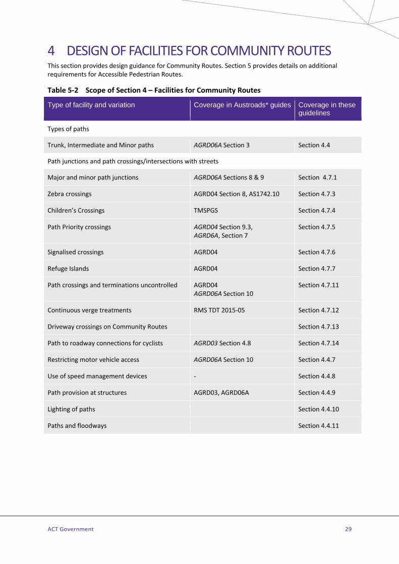
ACT Government 29
4 DESIGN OF FACILITIES FOR COMMUNITY ROUTES This section provides design guidance for Community Routes. Section 5 provides details on additional requirements for Accessible Pedestrian Routes.
Table 5-2 Scope of Section 4 – Facilities for Community Routes
Type of facility and variation Coverage in Austroads* guides Coverage in these guidelines
Types of paths
Trunk, Intermediate and Minor paths AGRD06A Section 3 Section 4.4
Path junctions and path crossings/intersections with streets
Major and minor path junctions AGRD06A Sections 8 & 9 Section 4.7.1
Zebra crossings AGRD04 Section 8, AS1742.10 Section 4.7.3
Children’s Crossings TMSPGS Section 4.7.4
Path Priority crossings AGRD04 Section 9.3, AGRD6A, Section 7
Section 4.7.5
Signalised crossings AGRD04 Section 4.7.6
Refuge Islands AGRD04 Section 4.7.7
Path crossings and terminations uncontrolled AGRD04 AGRD06A Section 10
Section 4.7.11
Continuous verge treatments RMS TDT 2015-05 Section 4.7.12
Driveway crossings on Community Routes Section 4.7.13
Path to roadway connections for cyclists AGRD03 Section 4.8 Section 4.7.14
Restricting motor vehicle access AGRD06A Section 10 Section 4.4.7
Use of speed management devices - Section 4.4.8
Path provision at structures AGRD03, AGRD06A Section 4.4.9
Lighting of paths Section 4.4.10
Paths and floodways Section 4.4.11
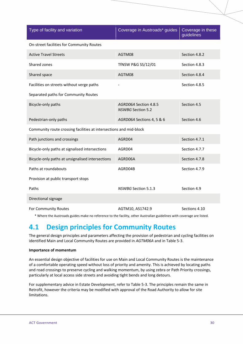
ACT Government 30
Type of facility and variation Coverage in Austroads* guides Coverage in these guidelines
On-street facilities for Community Routes
Active Travel Streets AGTM08 Section 4.8.2
Shared zones TfNSW P&G SS/12/01 Section 4.8.3
Shared space AGTM08 Section 4.8.4
Facilities on streets without verge paths - Section 4.8.5
Separated paths for Community Routes
Bicycle-only paths AGRD06A Section 4.8.5 NSWBG Section 5.2
Section 4.5
Pedestrian-only paths AGRD06A Sections 4, 5 & 6 Section 4.6
Community route crossing facilities at intersections and mid-block
Path junctions and crossings AGRD04 Section 4.7.1
Bicycle-only paths at signalised intersections AGRD04 Section 4.7.7
Bicycle-only paths at unsignalised intersections AGRD06A Section 4.7.8
Paths at roundabouts AGRD04B Section 4.7.9
Provision at public transport stops
Paths NSWBG Section 5.1.3 Section 4.9
Directional signage
For Community Routes AGTM10, AS1742.9 Sections 4.10
* Where the Austroads guides make no reference to the facility, other Australian guidelines with coverage are listed.
4.1 Design principles for Community Routes The general design principles and parameters affecting the provision of pedestrian and cycling facilities on identified Main and Local Community Routes are provided in AGTM06A and in Table 5-3.
Importance of momentum
An essential design objective of facilities for use on Main and Local Community Routes is the maintenance of a comfortable operating speed without loss of priority and amenity. This is achieved by locating paths and road crossings to preserve cycling and walking momentum, by using zebra or Path Priority crossings, particularly at local access side streets and avoiding tight bends and long detours.
For supplementary advice in Estate Development, refer to Table 5-3. The principles remain the same in Retrofit, however the criteria may be modified with approval of the Road Authority to allow for site limitations.
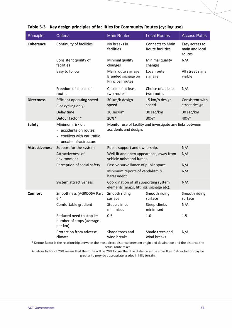
ACT Government 31
Table 5-3 Key design principles of facilities for Community Routes (cycling use)
Principle Criteria Main Routes Local Routes Access Paths
Coherence Continuity of facilities No breaks in facilities
Connects to Main Route facilities
Easy access to main and local routes
Consistent quality of facilities
Minimal quality changes
Minimal quality changes
N/A
Easy to follow Main route signage Branded signage on Principal routes
Local route signage
All street signs visible
Freedom of choice of routes
Choice of at least two routes
Choice of at least two routes
N/A
Directness
Efficient operating speed (For cycling only)
30 km/h design speed
15 km/h design speed
Consistent with street design
Delay time 20 sec/km 30 sec/km 30 sec/km Detour factor * 20%* 30%* 40%*
Safety Minimum risk of: - accidents on routes - conflicts with car traffic - unsafe infrastructure
Monitor use of facility and investigate any links between accidents and design.
Attractiveness Support for the system Public support and ownership. N/A Attractiveness of environment
Well-lit and open appearance, away from vehicle noise and fumes.
N/A
Perception of social safety Passive surveillance of public space. N/A Minimum reports of vandalism & harassment.
N/A.
System attractiveness Coordination of all supporting system elements (maps, fittings, signage etc).
N/A.
Comfort Smoothness (AGRD06A Part 6.4
Smooth riding surface
Smooth riding surface
Smooth riding surface
Comfortable gradient Steep climbs minimised
Steep climbs minimised
N/A
Reduced need to stop ie: number of stops (average per km)
0.5 1.0 1.5
Protection from adverse climate
Shade trees and wind breaks
Shade trees and wind breaks
N/A
* Detour factor is the relationship between the most direct distance between origin and destination and the distance the actual route takes.
A detour factor of 20% means that the route will be 20% longer than the distance as the crow flies. Detour factor may be greater to provide appropriate grades in hilly terrain.

ACT Government 32
4.2 Design requirements and criteria for paths on Community Routes
The ATRA shows the spatial route alignments and the hierarchy for Community Routes within future urban and established areas. Community Routes may include facilities located within the street verge or in open space reserves and may be co-located with floodways, landscape corridors or wetlands and retention basins. The path facilities provided on Community Routes within street corridors may vary against the EDC requirement when other route-siting opportunities are applied.
Facilities on Community Routes are provided in accordance with the route hierarchy as shown in ATRA. In street corridors Community Route facilities generally parallel On-Road Cycling facilities to provide for a wide range of cyclist needs. On most types of streets there is a verge path on each side to provide for Community Routes (see discussion below). Table 5-4 shows the provision for different types of Community Route facilities in Estate Development with reference to route hierarchy, land use context and the corridor where the route is located, open space reserve or a street verge.
The selection of facilities for use on CRs should always be considered according to the Community Route hierarchy and separately to the road network. For example, a Main or Local Community Route may be located in the verge on one side of a minor collector road (using a 3.0m wide trunk path) with an Access Community Route located on the opposite side of the road. The path type usually associated with this route type (ACR – General) is a minor path (1.5m wide). If this Access Community Route is a ACR-Special, for example located adjacent to a major community facility such as a school the facility type should be an intermediate path (2.0m wide) or may be a fully paved verge.
The siting of Main and Local Community Routes should ensure that property accesses do not impede or present a hazard to users of these facilities and are not generally permitted across these route types.
Table 5-4 Community Route facilities in Estate Development
Community Route type
Typical corridor types
Typical AT Facility provision for Inner Urban land use
Typical AT Facility provision for Suburban land use
Typical crossing provision
Main Open space, Parkways, Arterials, Major collectors
Trunk path Bicycle-only path
In road corridor separated in landscaped verge or through greenspace areas
Traffic signals Grade separated (under or overpasses)
Minor collectors Local access
Trunk path Bicycle-only path Marked paved verge Active Travel Street Shared space
Trunk path (No driveway accesses) Bicycle-only path (bus routes) Active Travel Streets
Path Priority crossing (May also use Zebra crossing if low cyclist and higher pedestrian volumes)
Local route Open space, Parkways, Arterials, Major collectors
Trunk path Bicycle-only path
In road corridor separated in landscaped verge or through greenspace areas
Traffic signals Grade separated (under or overpasses)

ACT Government 33
Community Route type
Typical corridor types
Typical AT Facility provision for Inner Urban land use
Typical AT Facility provision for Suburban land use
Typical crossing provision
Minor collectors Local access
Trunk path Bicycle-only path Marked paved verge Active Travel Street Shared space
Trunk path (No driveway accesses) Bicycle-only path (bus routes) Active Travel Streets
Zebra (May also use Path Priority crossing if higher cyclist volumes)
Access route – General
Arterials, Major collectors
Minor path or fully paved verge for destination connectivity
Minor path for network connectivity
Traffic signals Grade separated (under or overpasses)
Minor collectors Local access
Minor path or fully paved verge for destination connectivity
Minor path for network connectivity
Zebra (If warranted)
Access route – Special
Minor collectors Local access
Fully paved verge Intermediate path
Intermediate or trunk path
School Zebra (If warranted)
Access route – Feeder
Open space Arterial Major collector Minor collectors Local access
Fully paved verge Active Travel Street Shared space
Intermediate or trunk path Bicycle-only path Active Travel Streets In road corridor separated in landscaped verge or greenspace areas
Zebra (If warranted) Path Priority crossing (for bicycle-only path)
In relation to the road network, facilities for Community Routes are generally provided along both sides of collectors but provided only on one side of minor local access streets. Facilities for Community Routes are not located close to arterial roads if more appropriate alignments are available through adjacent open space. Access Community Routes provide network connectivity and facilities for these routes are generally minor paths but may be wider paths or other facilities if an ACR - Feeder or – Special. ACRs should exist wherever people need to travel by foot or bike such as to public transport stops and community facilities. Refer to Figure 5-2 for an illustration of the Community Routes referenced against road hierarchy.
Paths are the primary type of facility used for Main and Local Community Routes and may be shared or separated. Paths within parks having a recreational function only and accessing local facilities usually form Recreational Routes (refer Section 8).
All paths in the ACT can be legally used by pedestrians and cyclists so it is not necessary to sign paths as shared paths except in legacy locations where paths are shared with equestrians. In these situations, additional signage is used to indicate the wider shared use (see ACTSD-0611).
On paths, pedestrians and users of wheelchairs, including motorised wheel-chairs, have priority over cyclists (including e-bikes) and users of wheeled recreational devices (scooters, rollerblades, roller skates

ACT Government 34
and skateboards) and behavioural signage (refer to Section 4.10.9). is used where needed along with appropriate directional and wayfinding signage (refer to Section 4.10).
Estate development
Main, Local and Access Community Routes generally utilise paths and are designed for pedestrians and cyclists in accordance with the relevant ACTSD, the Estate Development Code and the approved Estate Development Plan. Design issues to address include:
> All new neighbourhoods should be made walking and cycling-friendly by following the key design principles outlined in Section 3.
> Community Routes facilities such as paths are generally located on both sides of the roadway however there are exceptions and the ATRA should be referenced for all Main and Local Community Route alignments. A trunk path may be provided for a Main or Local Community Route on one side of a street and a minor path provided on the other side for an Access Community Route. Facilities on Access Community Routes are provided extensively to ensure the door to door connectivity of the network.
> Main and Local Community Routes need not necessarily follow road alignments. When these routes are located in verges, facility provision is influenced by land use as shown in Table 5-4.
> Access Community Routes generally utilise minor paths except where identified as a Feeder or Special ACR where wider paths or other facilities may be required. Overlap of route types may also require a wider path for the Access Community Route.
> Refer to Figure 5-2 for examples of facilities on active travel routes referenced to road hierarchy. The example facilities may need to be modified if there is an overlay of a special needs or active recreational travel route.
Estate Development and Retrofit
Paths
> Path design should meet the requirements of people with disabilities for access to public transport, including connecting paths and suitable crossing points. Paths on APRs should be designed to specific requirements, refer Section 5.
> Paths should follow "desire lines" as closely as possible, except when there is reason to believe that factors such as danger or inconvenience have discouraged the use of potentially valuable routes.
> Paths should be designed appropriately to suit the environment. > Minimum clearances may not be applicable where road and open space planning provides ample
space for paths to be located with greater separations to trees, kerbs, fences, etc.
Refer to MIS 14 Public lighting for requirements for lighting of paths and pedestrian underpasses.
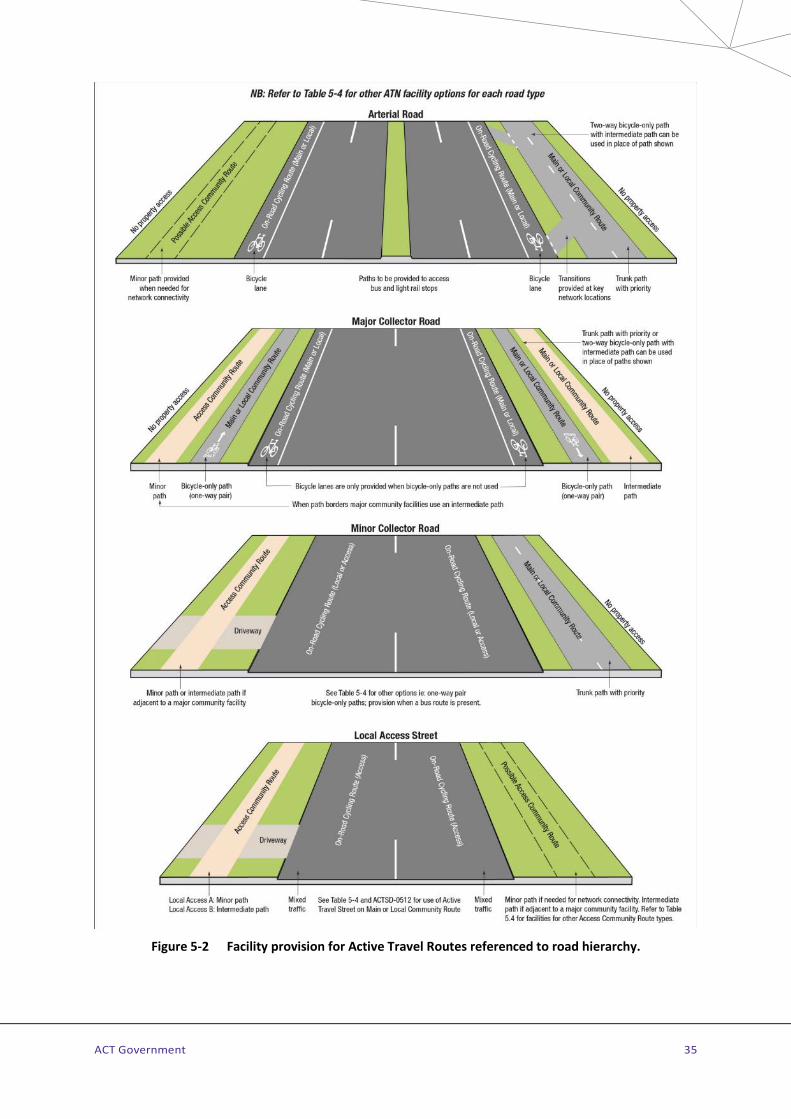
ACT Government 35
Figure 5-2 Facility provision for Active Travel Routes referenced to road hierarchy.
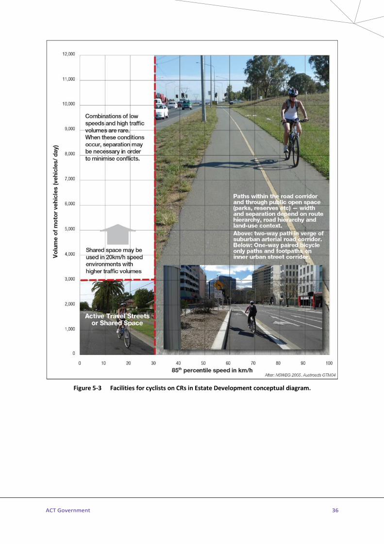
ACT Government 36
Figure 5-3 Facilities for cyclists on CRs in Estate Development conceptual diagram.

ACT Government 37
Bicycle facilities
Figure 5-3 presents different types of appropriate facilities for bicycle use on Main and Local Community Routes, on or away from road corridors in Estate Development. Key design considerations are represented by the two axes of the graph: vertical, representing traffic volume; and, horizontal, representing traffic speed of the adjacent roadway.
> The relationship between the prevailing traffic speed and volume is an important factor in the decision to provide and locate cycling facilities for Main and Local Community Routes either as separated from the roadway, or as mixed traffic. Where cycling is on the roadway, paths are always provided for pedestrians and as an alternative for cyclists who prefer off-road conditions (children, elderly and inexperienced).
> Separation of bicycles from vehicles is beneficial to all road users, refer to Section 4.5 for guidance on separated facilities.
Retrofit only
Facilities should be provided to meet the appropriate requirements of this Standard. In some Retrofit situations facilities of a lower standard may be preferable to doing nothing at all.
The minimum criteria may only be adopted where “desirable” criteria are not achievable because of physical conditions such as existing boundaries, services and landscape or budget limitations.
Guidance on the type of facilities where a lower standard is acceptable are included in this Design Standard. Proposals not complying with this Design Standard must be discussed with the Road Authority and endorsement obtained prior to submitting the design for approval.
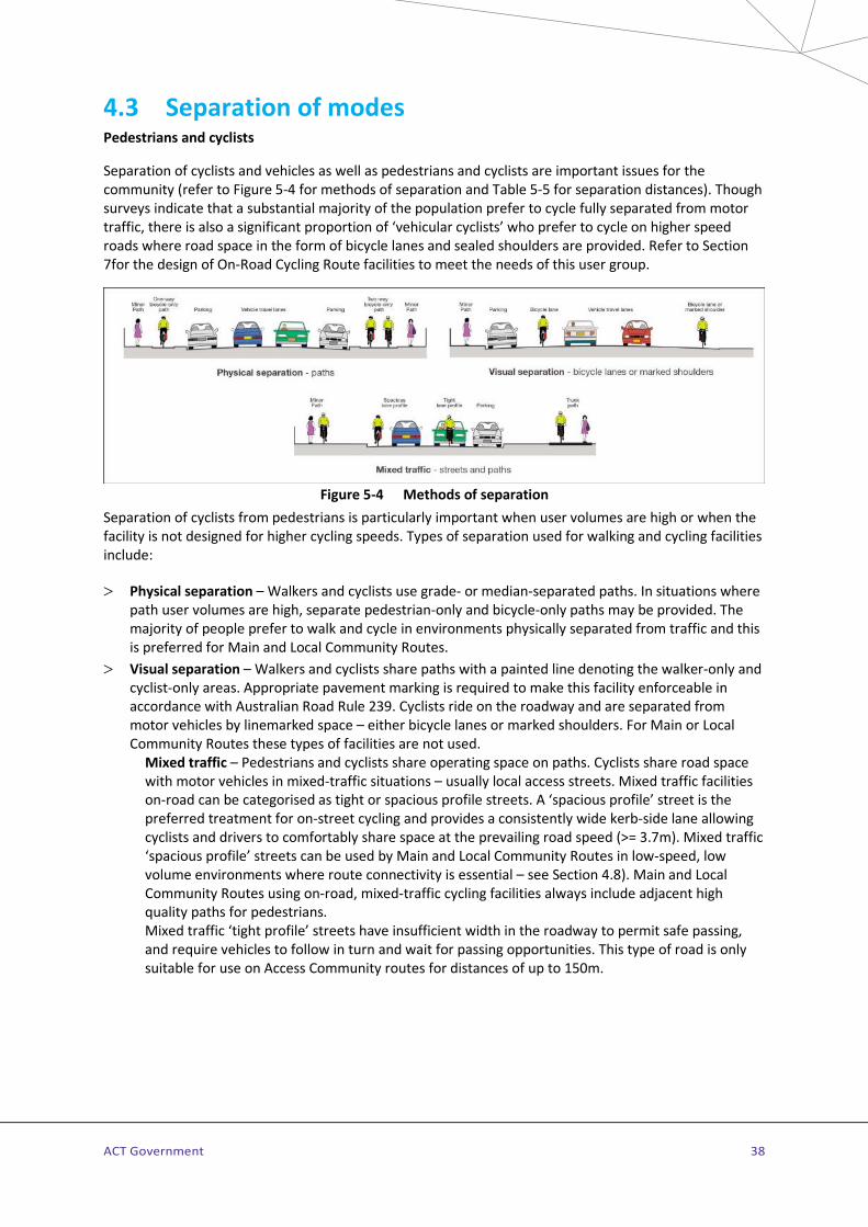
ACT Government 38
4.3 Separation of modes Pedestrians and cyclists
Separation of cyclists and vehicles as well as pedestrians and cyclists are important issues for the community (refer to Figure 5-4 for methods of separation and Table 5-5 for separation distances). Though surveys indicate that a substantial majority of the population prefer to cycle fully separated from motor traffic, there is also a significant proportion of ‘vehicular cyclists’ who prefer to cycle on higher speed roads where road space in the form of bicycle lanes and sealed shoulders are provided. Refer to Section 7for the design of On-Road Cycling Route facilities to meet the needs of this user group.
Figure 5-4 Methods of separation
Separation of cyclists from pedestrians is particularly important when user volumes are high or when the facility is not designed for higher cycling speeds. Types of separation used for walking and cycling facilities include:
> Physical separation – Walkers and cyclists use grade- or median-separated paths. In situations where path user volumes are high, separate pedestrian-only and bicycle-only paths may be provided. The majority of people prefer to walk and cycle in environments physically separated from traffic and this is preferred for Main and Local Community Routes.
> Visual separation – Walkers and cyclists share paths with a painted line denoting the walker-only and cyclist-only areas. Appropriate pavement marking is required to make this facility enforceable in accordance with Australian Road Rule 239. Cyclists ride on the roadway and are separated from motor vehicles by linemarked space – either bicycle lanes or marked shoulders. For Main or Local Community Routes these types of facilities are not used.
Mixed traffic – Pedestrians and cyclists share operating space on paths. Cyclists share road space with motor vehicles in mixed-traffic situations – usually local access streets. Mixed traffic facilities on-road can be categorised as tight or spacious profile streets. A ‘spacious profile’ street is the preferred treatment for on-street cycling and provides a consistently wide kerb-side lane allowing cyclists and drivers to comfortably share space at the prevailing road speed (>= 3.7m). Mixed traffic ‘spacious profile’ streets can be used by Main and Local Community Routes in low-speed, low volume environments where route connectivity is essential – see Section 4.8). Main and Local Community Routes using on-road, mixed-traffic cycling facilities always include adjacent high quality paths for pedestrians. Mixed traffic ‘tight profile’ streets have insufficient width in the roadway to permit safe passing, and require vehicles to follow in turn and wait for passing opportunities. This type of road is only suitable for use on Access Community routes for distances of up to 150m.

ACT Government 39
Separated facilities in Estate development
The primary method of separation from motor vehicles for Community Routes is physical separation located in the verge, either paths or bicycle-only paths combined with paths. The minimum recommended separation of paths from traffic lanes is as shown in Table 5-5. Separation between cyclists and pedestrians is provided in high-volume situations and where safe sharing is compromised by restricted path width or the character of the path environment (APR, passive recreation areas, near aged care facilities etc).
Main and Local Community Routes can utilise Active Travel Streets, mixed traffic local access streets which have been traffic calmed to remove traffic volumes and reduce traffic speeds - see Section 4.8.2.
Table 5-5 Minimum separation from traffic lanes for paths
Road speed environment
Separation width*
Road environment
Recommended kerb
Comments
<60km/h 1.0m Parking permitted
Barrier kerb
400mm No parking Barrier kerb
60-80km/h 3.0m No parking Mountable kerb and verge
Passive surveillance and light spill from the road should be considered in setting the path offset.
80-100km/h 5.0m No parking Mountable or flush kerb and verge
Crash barrier at locations of potential road traffic run-off. Passive surveillance and light spill from the road should be considered in setting the path offset.
>100km/h 8.0m No parking Mountable or flush kerb and verge with vegetation
Crash barrier at locations of potential road traffic run-off
* This dimension is the minimum separation width measured from the edge of the traffic lane to the inside edge of the path
Separated facilities in Retrofit only
The inclusion of a single separated facility to serve both Community and On-Road Cycling Routes should not lead to a loss of functionality for existing On-Road Cycling Route users. The operating needs of existing users (training/high speed commuters) to be preserved in any joint facility are:
> priority at intersections; > riding two abreast; > treatment of the facility at intersections and roundabouts; and, > issues which affect safety when travelling at speed, such as the space to avoid debris/broken glass by
moving into a traffic lane, and overtaking parked vehicles and buses at bus stops.
Physical separation devices must not pose a hazard to cyclists or motor vehicles. Any hazard potentially resulting from a proposed separation device should be assessed and endorsed by the Road Authority as acceptable prior to installation.

ACT Government 40
4.4 Paths on Community Routes Estate development
Table 5-6 details the path types and dimensions in use in the ACT in Estate Development.
Table 5-6 Path types
Facility type Community Route level and land use
Function Width
Minor Path Access - General Predominately for pedestrian use, cyclist use permitted: low volumes, Local access street A.
1.5m
Intermediate Path
Access - General Predominately for pedestrian use, cyclist use permitted, Local access street B.
2.0m
Intermediate / Trunk Path
Access – Special Higher levels of pedestrian and/or cyclist use associated with a major community facility
2.0m – 3.0m*
Access – Feeder Higher levels of pedestrian and/or cyclist use associated with access from a residential catchment to a Main or Local Community Route
2.0m – 3.0m*
Trunk Path
Main or Local in suburban or inner urban land use
High levels of pedestrian and cyclist use in both directions: commuting; speeds greater than 20km/h. May require greater width when overlaid with an APR or RR.
5.0m* 3.0m min
Bicycle-only path (one-way pair)
Main or Local in inner urban land use
Bicycle-only use where separation from pedestrians is required due to conflict issues, high volumes or other reasons including overlay with APR or RR.
2.0m 1.5m min if no kerbs*
Main, Local or Access – Feeder on major collector roads in suburban land use
May be considered to achieve separation of cyclists from both vehicles and pedestrians
Access on minor collector roads with a bus route in suburban areas
May be considered for use on minor collector roads with a bus route in suburban land use, verge paths may be reduced to 1.5m.
Bicycle-only path (two-way)
Main or Local in inner urban land use
Bicycle-only use where separation from pedestrians is required due to conflict issues, high volumes or other reasons including overlay with an APR or RR.
3.0m 2.5m min* Main, Local or Access –
Feeder in suburban land use May be considered to achieve separation of cyclists from both vehicles and pedestrians
Pedestrian-only path
Main in inner urban land use Pedestrian-only use where separation from cyclists is required due to conflict issues, high volumes or other reasons including the presence of an APR or RR.
2.0m 1.5m min*
* Refer to AGRD06A Section 5.3 and Queensland Transport and Main Roads Technical Note 133: Guidance on the Widths of Shared Paths and Separated Bicycle Paths for additional guidance on calculating the optimum widths of paths and bicycle-only paths according to user
volumes. Paths may be wider due to overlay of other route types including a Recreational Route.
ACT Government 41
Retrofit
Existing paths on Community Routes as identified in the ATRA are to be upgraded on replacement of any demolished sections of path generally greater than 50m in length. A minimum path width of 3.0m is required on Main Community Routes and a minimum path width of 2.5m on Local Community Routes.
4.4.1 Path design Estate Development and Retrofit
Path design is to consider land use and route hierarchy contexts. For example, a trunk path on a Main Community Route through a green corridor in a suburban context will have a higher design speed than a trunk path on Local Community Route in an inner urban context. Path design will comply with AGRD06A, references to the relevant sections of AGRD06A are shown in brackets:
> Width (AGRD06A Section 5.1) > Bicycle operating speeds (AGRD06A Section 5.2) > Horizontal curvature (AGRD06A Section 5.3) > Path gradients (AGRD06A Section 5.4) > Clearances and the need for fences (AGRD06A Section 5.5) > Crossfall and drainage (AGRD06A Section 5.6) > Sight distance (AGRD06A Section 5.7) > Changes in level (AGRD06A Section 5.8) > Surface treatments and tolerances (AGRD06A Section 5.9 and 5.10) > Lighting and underground services (AGRD06A Section 5.11 and 5.12)
Paths should not be located directly adjacent to property boundaries because of the risk of blind spots particularly from drivers exiting from driveways. Paths should not be located abutting kerbs as they may locate path users in the car door opening zone or may be obstructed by refuse bins on collection days (see Table 5-5). Refer to MIS 01 Street planning and design for technical requirements for street cross section planning.
4.4.2 Path gradient and disabled access Estate Development and Retrofit
Path design and construction will incorporate disabled access in accordance with AS1428.1 Design for Access and Mobility and AS1428.4 Tactile Indicators where these paths form part of an Accessible Pedestrian Route (refer Section 5). The location of APRs may be found in the ATRA.
For minor paths, the Key Documents do not give clear guidance on requirements for maximum gradient. Paths associated with building developments should comply with AS1428. It is not always possible to apply this standard to all minor paths, eg. suburban land use area paths in verges with steep slopes. However, all paths in inner urban land use areas should be designed to meet the requirements wherever possible.
ACT Government 42
Table 5-7 recommends suitable pedestrian pathway gradients. In cases of minor non-compliance, practitioners should identify alternative routes. If an APR requires realignment from that shown in ATRA the alignment should be amended as detailed in the PATACT.
Ramps and stairs comply with AS1657 Fixed platforms, walkways, stairways and ladders and AS1428.1. Careful consideration should be given to the treatment of approaches to crossings on steeper paths.
Table 5-7 Minor path gradients
Gradient Type Conditions Compliance with Access & Mobility
< 3% Minor path NIL Yes
3% to 5% Minor path – suburban NIL No
3% to 5% Minor path – APR or inner urban
1.5m landings every 18m for 3% grade (landings every 25m for 5% grade). Can include driveways as landings.
Yes
5% to 7% Ramp* – APR or inner urban
To be AS1428 compliant a step ramp must be used.
No. See comment left
5% to 12.5% Minor path NIL No
> 37% Stairs NIL No
* Ramps are not suitable in urban environments.
4.4.3 Path cross section Estate Development and Retrofit
The Key Documents provide the design requirements for the cross section details of various path types. Notwithstanding these requirements, paths will comply with the following:
> Maximum 4% crossfall and clear of obstacles for 1.0m (absolute minimum 0.5m in Retrofit) on Main and Local Community Routes. On minor paths, clearances may be reduced to 0.5m. In new areas and Retrofit situations with consistently steep terrain, a greater path crossfall may be used with the approval of the Road Authority after due consideration of path usage.
> Maximum 2.5% crossfall for paths on Accessible Pedestrian Routes. > For paths on Main and Local Community Routes, a 1.0m wide “shoulder” (absolute minimum 0.5m in
Retrofit) has the same crossfall as the path before transitioning to the batter slope.
Path cross section details are shown in ACTSD-0501.
4.4.4 Pavement materials Estate Development and Retrofit
The most appropriate pavement type should be selected to suit the particular specific or shared function. See MIS 01 Street planning and design for details.
Paths may use the following pavement types:
> Asphalt (preferred pavement type for trunk paths on Main and Local Community Routes with the exception of special treatments at path junctions);

ACT Government 43
> In situ reinforced concrete (preferred type for intermediate and minor paths adjacent to a street in the verge);
> Clay or concrete pavers (pavers are to be avoided as a surfacing on Main Community Routes likely to be used by higher speed commuter and training cyclists); and,
> Composite surfaces.
Construction details for path pavement materials used on Community Routes are shown in ACTSD-0501.
4.4.5 Pavement design Estate development
Practitioners should adopt the pavement designs shown in MIS 03 Pavement design and ACTSD-0501.
Flexible pavements with asphalt surfacing should be used for paths on Main and Local Community Routes only. Asphalt paths may be edged to prevent spreading and cracking of the pavement dependant on adjoining landscape treatments. Path edging will be flush to the pavement with a 1.0m run-off area on each side of the path. Root barriers are installed where there is a risk of damage by invasive plant species and as a measure to precent longitudinal cracking in asphalt pavements due to clay subgrades (refer to ACTSD-0501 for details).
Concrete is the preferred surface treatment for minor paths and intermediate paths within the verge. Reinforcement should be included in concrete paths if they are constructed prior to completion of building construction.
Appropriate reinforcement is included where service pits are installed in any pathway. Service pits located under or to the side of paths will have non-slip, flush covers with associated pavement jointing smoothly filled.
Retrofit only
Typical path pavement design details for use on Community Routes in Retrofit are shown in ACTSD-0501. Asphalt is preferred for use on trunk paths retrofitted on Main and Local Community Routes.
Retrofitted paths are designed to match the pavement of all connecting paths. Concrete with black oxide is preferred when patching asphalt paths following services installations. The section of path cut out should be wide enough to allow the reinforced patching slab to bridge the services trench.
4.4.6 Proximity of trees, root barriers and moisture control barriers Estate Development and Retrofit
Where trees, tree roots, or wet shaded zones may damage pavement surfaces, consideration needs to be given to the selection of suitable paving material and to the existing or planned trees policy. Root barriers are to be installed when paths are located close to tree species that have invasive roots. A desirable clearance between vegetation and path edge of 1.0m (500 minimum) should be provided.
Refer MIS 24 Soft landscape design for details of when root barriers are required and for water sensitive design techniques.
Asphalt paths are susceptible to longitudinal cracking in a Canberra context when underlain by thicker layers of local clay subgrades. To reduce the moisture variation in clay subgrades under asphalt paths the installation of moisture control barriers as detailed on ACTSD-0501 is recommended.

ACT Government 44
4.4.7 Vehicle access restriction to paths Estate Development and Retrofit
Physical barriers are often necessary to prevent damage by unauthorised vehicles to parkland or infrastructure such as bridges not designed to take the weight of a vehicle. Barriers placed at the termination of paths, on bridge approaches and at property boundaries can present a danger to cyclists and pedestrians if not carefully designed and sited.
Access restriction devices to prevent unauthorised vehicle entry should be assessed in conjunction with the land custodian of the affected area or asset (bridges etc) and installed only if the following conditions are warranted:
> there is a documented recurrent issue with unauthorised vehicle access; > an existing contiguous barrier designed to protect the asset is not effective in preventing vehicle
access; > the issue cannot be resolved by other methods (CCTV, police enforcement, user reports); or, > vehicle access may damage path infrastructure (for example, lightweight bridges etc).
Acceptable arrangements of physical barriers for use in the ACT depend on Community Route hierarchy level and land use context (inner urban or suburban). Guidance on the provision of physical barriers is shown with reference to path width and ACTSD-0502 provides details for trunk and intermediate paths and ACTSD-0503 for minor paths.
Retrofit only
On Main or Local Community Routes with intermediate paths where space adjacent to the path is not available for widening and central positioning of a bollard, the path edge may be restricted through the use of bollards and line marking as detailed in ACTSD-0502.
Vehicle restriction (banana) rails may not be used as access restriction devices under any circumstances.
Assessment of the need to install physical barriers should follow an approach similar to the US Federal Highway Administration’s web-based guidance tool “Bicycle Path Entry Control”, proposing an escalating approach to access management – if the first step does not work, escalate to the next:
1. Install regulatory signs identifying the infrastructure as a path which prohibits motor vehicle entry. In the case of regular park vehicle use, install “authorised vehicles only” and load limit signage at the entry.
2. Re-design path entry appearance to discourage vehicle access.
3. Use physical barriers as a last resort, where the risk of damage to infrastructure from occasional unauthorised entry exceeds the risk of a permanent hazard to path users. Provide separate authorised vehicular access for maintenance/emergency vehicles where possible.
4. Barriers on paths through reserves regularly used by park maintenance must be removable to allow temporary vehicle access. Temporary barriers should not present a hazard to users when they are removed or when in the opened state. Use flush mounted footing covers and locks.
5. When path entry gates are used, a permanent well-marked two-way paved bypass path(s) should be constructed to the side of the gate. The gate should be fitted with hazard marking using reflective tape in the standard white/red/white pattern.
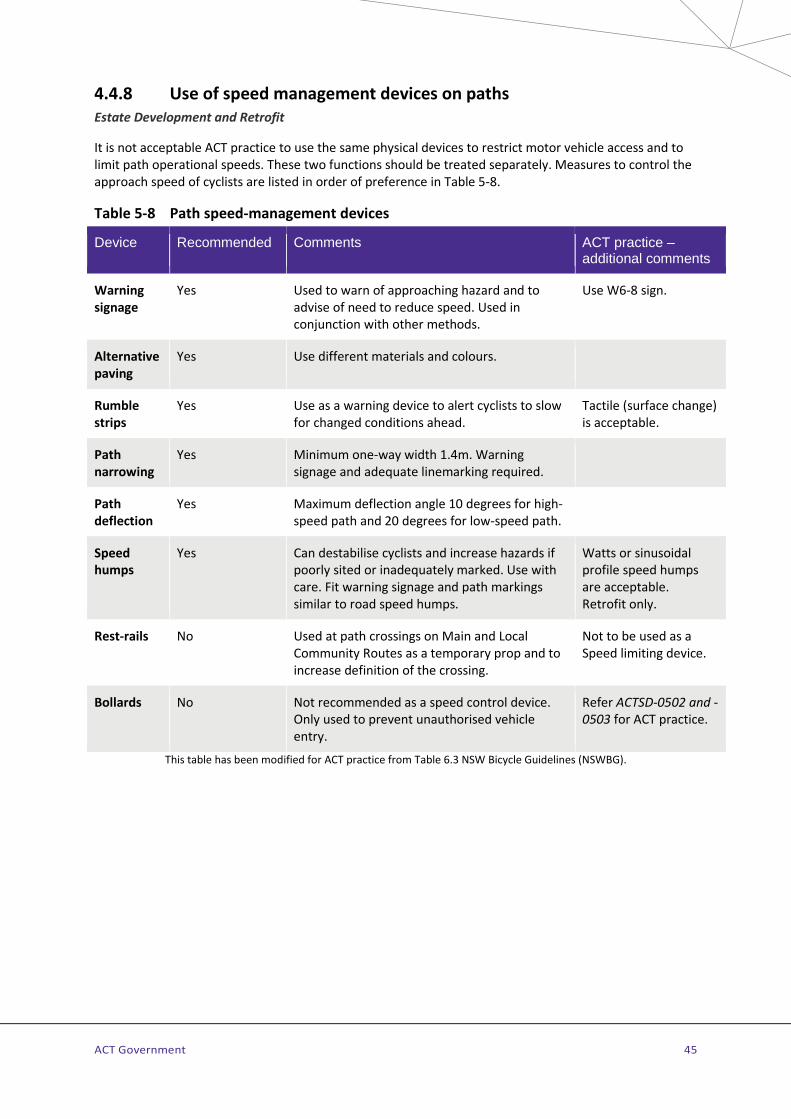
ACT Government 45
4.4.8 Use of speed management devices on paths Estate Development and Retrofit
It is not acceptable ACT practice to use the same physical devices to restrict motor vehicle access and to limit path operational speeds. These two functions should be treated separately. Measures to control the approach speed of cyclists are listed in order of preference in Table 5-8.
Table 5-8 Path speed-management devices
Device Recommended Comments ACT practice – additional comments
Warning signage
Yes Used to warn of approaching hazard and to advise of need to reduce speed. Used in conjunction with other methods.
Use W6-8 sign.
Alternative paving
Yes Use different materials and colours.
Rumble strips
Yes Use as a warning device to alert cyclists to slow for changed conditions ahead.
Tactile (surface change) is acceptable.
Path narrowing
Yes Minimum one-way width 1.4m. Warning signage and adequate linemarking required.
Path deflection
Yes Maximum deflection angle 10 degrees for high-speed path and 20 degrees for low-speed path.
Speed humps
Yes Can destabilise cyclists and increase hazards if poorly sited or inadequately marked. Use with care. Fit warning signage and path markings similar to road speed humps.
Watts or sinusoidal profile speed humps are acceptable. Retrofit only.
Rest-rails No Used at path crossings on Main and Local Community Routes as a temporary prop and to increase definition of the crossing.
Not to be used as a Speed limiting device.
Bollards No Not recommended as a speed control device. Only used to prevent unauthorised vehicle entry.
Refer ACTSD-0502 and -0503 for ACT practice.
This table has been modified for ACT practice from Table 6.3 NSW Bicycle Guidelines (NSWBG).
ACT Government 46
4.4.9 Provision for paths at bridges and underpasses Estate Development and Retrofit
Paths should be designed for uninterrupted movement and provide adequate clearances from barriers, fences, bridges, trees, adjoining vegetation, underpasses and vertical walls. Refer to AGRD06A Section 5.5 and Appendices for design requirements.
The Key Documents provide information on:
> Minimum and desirable widths and clearances for path types – AGRD06A Section 5.1. > Handrails, batters and fences – AGRD06A Section 5.5. > Bridges and approach ramps– AGRD06A Section 8.2. > Underpasses – AGRD06A Section 8.3. > Refer to MIS 09 Bridges and related structures for specific requirements for bridges on municipal
roads (to major collectors) and TRIS 07 Bridges and related structures for bridges on arterial roads.
Arterial road underpasses used by paths on Community Routes and shared with equestrians are designed and managed using the additional guidance provided in Section 6.2.3.
Where a path forming a Main or Local Community Route is adjacent to the road and is required to be continuous along the road route, the path is continued across the bridge at the same path width with a minimum clearance to balustrades on each side of 500mm. It is generally not acceptable to divert a path from the bridge to dip through an underpass or low level crossing.
4.4.10 Lighting of paths, bridges and underpasses Estate development
Main and Local Community Routes including priority crossings and underpasses remote from the street lighting system are to be adequately illuminated for public safety and community surveillance in accordance with MIS14 Public Lighting.
Retrofit only
The Road Authority will assess lighting requirements on a site by site basis according to community need and operational safety requirements. Refer to AGRD06A Section 5.11 for guidance on path lighting in locations remote from the road network street lighting system.

ACT Government 47
4.4.11 Paths and floodways Estate development
Paths should be designed to protect pedestrians and cyclists from flood events and provide access to suitable alternatives in the event of flooding.
Paths forming Main or Local Community Routes should be located above the flood level of a storm event with a 20% Annual Exceedance Probability (AEP). When paths are within the flood area of larger waterways such as major rivers or creeks with faster moving water and longer inundation periods, a higher level of protection up to 10% AEP is to be considered.
Paths parallel to floodways should be as high as possible. Recreational paths not serving a transport function may be protected against lower AEP events, but consideration should be given to maintenance requirements resulting from more frequent inundation.
At-grade floodway crossings may be provided for Minor and Intermediate Paths (Access routes) under the following conditions:
> Consideration has first been given to utilising nearby existing or proposed alternative high level crossings.
> Suitable structures satisfy appropriate performance criteria for paths on Main and Local Community Routes.
Retrofit only
In Retrofit, protection of paths to less than a 20% AEP flood event may be appropriate with careful consideration of the following:
> Need for the path. > Economic feasibility of providing 20% AEP flood event protection. > Suitable alternatives for when the path is unserviceable. > Length of time path is unserviceable in the 20% AEP flood event. > Risk of use in the 20% AEP flood event; danger of depth and velocity of flow. > Relaxation of the 20% AEP flood protection requires the endorsement of the Road Authority.
Where there is a definite desire line of travel that crosses a floodway for any type of path and a good quality high level crossing exists nearby (to which the cycleway or footpath would be connected), then the desire line can also be satisfied by an at-grade crossing.
4.4.12 Traffic calming devices interaction with paths Estate Development and Retrofit
Where raised platforms are installed for LATM purposes, there should be no ambiguity as to the raised platform being used as a zebra crossing. If there is a risk of use as a de facto zebra crossing, suitable landscape treatment or barriers should be installed to discourage crossing by pedestrians. Raised platforms should not be installed on pedestrian desire lines to avoid this possibility. Refer to AGTM08 Figure 7.5 and ACTSD-3531 for details.
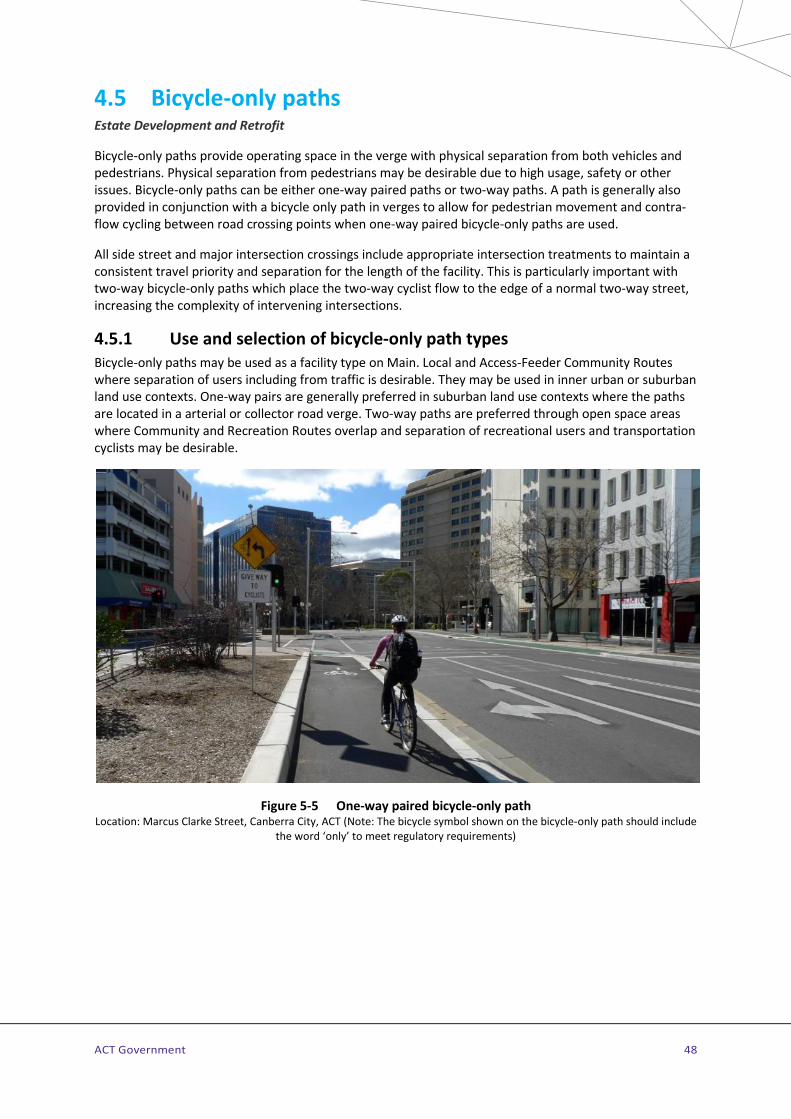
ACT Government 48
4.5 Bicycle-only paths Estate Development and Retrofit
Bicycle-only paths provide operating space in the verge with physical separation from both vehicles and pedestrians. Physical separation from pedestrians may be desirable due to high usage, safety or other issues. Bicycle-only paths can be either one-way paired paths or two-way paths. A path is generally also provided in conjunction with a bicycle only path in verges to allow for pedestrian movement and contra-flow cycling between road crossing points when one-way paired bicycle-only paths are used.
All side street and major intersection crossings include appropriate intersection treatments to maintain a consistent travel priority and separation for the length of the facility. This is particularly important with two-way bicycle-only paths which place the two-way cyclist flow to the edge of a normal two-way street, increasing the complexity of intervening intersections.
4.5.1 Use and selection of bicycle-only path types Bicycle-only paths may be used as a facility type on Main. Local and Access-Feeder Community Routes where separation of users including from traffic is desirable. They may be used in inner urban or suburban land use contexts. One-way pairs are generally preferred in suburban land use contexts where the paths are located in a arterial or collector road verge. Two-way paths are preferred through open space areas where Community and Recreation Routes overlap and separation of recreational users and transportation cyclists may be desirable.
Figure 5-5 One-way paired bicycle-only path Location: Marcus Clarke Street, Canberra City, ACT (Note: The bicycle symbol shown on the bicycle-only path should include
the word ‘only’ to meet regulatory requirements)
ACT Government 49
Figure 5-5 shows one-way paired bicycle-only paths on a street in an inner urban land use context. One-way bicycle-only path pairs are preferable to two-way bicycle-only paths in inner urban land use contexts as cyclists travel in the same direction on the same side of the street as other vehicular traffic resulting in fewer potential conflict points. The exception to this would be in inner urban land use where most of the destinations may lie on the inside of a loop and therefore make a two-way bicycle-only path on the same side preferable.
The downside of one-way paired bicycle-only paths can be connectivity to two-way facilities on one side of a road that require cyclists to cross the road, possibly twice to use the one-way pair. The location and area required to provide safe and attractive connections, including road crossings at each end should form a key consideration in the decision to select this facility type (Refer to ACTSD-0508 and -0509 for example facility connection details).
4.5.2 Design of bicycle-only paths Bicycle-only paths are part of the verge and are usually separated by a landscaped space, a kerb or a median separator and are regulated by a bicycle pavement symbol used with elongated “ONLY” lettering and directional arrow at the commencement of the facility or at intersections where other vehicular traffic may access the path. Refer to ACTSD-3522 for pavement marking arrangement details. A pavement marking symbol/arrow arrangement is used on separated paths to indicate travel direction. Solid edge lines in high traffic areas define the riding area and act as a navigation aid in low light conditions. Raised platforms with Priority crossings and green pavement treatment increase user awareness and route continuity at side street crossings.
Bicycle-only paths paralleling roads should be afforded the same priority as the parallel road at all minor street intersections. Australian Road Rule 71 provides for Give Way signage as a means of regulating approaching vehicles on side streets. Stop sign control is to be installed when warranted.
4.5.3 One-way paired bicycle-only paths One-way paired bicycle-only paths are usually located at verge level and are separated from the main carriageway by a landscaped verge or by a median separator (path at road grade). Refer to ACTSD-0506 for design details in Retrofit and inner urban land use context and ACTSD-0507 for suburban land use context. Where parking is permitted on the adjacent roadway the minimum verge width from the path or median separator is 1.0m to clear cyclists of the car-door zone. Where no parking is present, a 400mm minimum median may be used.
Use of one-way paired bicycle only paths remove the need to include bicycle lanes to cater for M/LORCRs on arterial and major collector roads. One-way paired bicycle only paths are designed for use by both on-road and community route cyclists as a single facility. The kerbside traffic lane should also be set to a width of more than 3.7m to allow sufficient width for a motorist and cyclist to safely share the lane in accordance with Austroads requirements.
The preferred treatments at unsignalised intersections and pavement markings for one-way paired bicycle-only paths are shown in ACTSD-0506 and -0507. At intersections with narrow verges and the bicycle-only path is located close to the kerb, a bent-in treatment, where the path is ramped down to the road and continued through the intersection as a bicycle lane, is recommended as shown on ACTSD-0506. Where the bicycle-only path is in a wider verge and located away from the kerb, a bent-out treatment as shown on ACTSD-0507 is recommended.
At minor intersections such as laneways in an inner urban land use, a continuous verge treatment can be used which maintains the bicycle-only path and the adjacent path at verge grade across the street opening. This treatment converts the side street crossing into a road related area where pedestrians and cyclists are afforded priority over vehicles crossing the road related area by Australian Road Rules 74 and 75.

ACT Government 50
The termination or connection (to continuing separated or shared paths) of one-way paired bicycle-only paths is designed and constructed to provide a safe and seamless connection with minimal loss of level of service. The connection of one-way paired paths to a two-way path requires the cyclists in one travel direction to cross the street to connect to the two-way path. This crossing is generally made mid-block as intersection transitions often involve multiple and complicated movements with increased risk of collision. See ACTSD-0508 for an example of a connection treatment between one-way paired and two-way bicycle-only paths and ACTSD-0509 for an example of a connection between a one-way paired bicycle-only path and a trunk path including to bicycle lanes.
4.5.4 Two-way bicycle-only paths In some street environments it may be preferable to provide a two-way bicycle-only path along one side of the street. This requires special design consideration at intersections as cyclists are using the path in a two-way direction in the verge of the adjacent two-way roadway. Standard Drawing ACTSD-0505 shows design details for this facility located either at verge-level in Estate Development or road-level allowable in Retrofit.
At larger intersections a bent-out treatment is used to create a crossing of the side street with sufficient offset to permit a vehicle turning into the side street to squarely face the control device (Path Priority crossing signs). At minor side street intersections in inner urban land use, a continuous verge treatment for the bicycle-only path and adjacent path can be provided using contrasting pavement material at verge level (see example in Figure 5-6).
Green coloured pavement treatment is to be used for 5m on each side of path junctions and continuous verge treatments where there is a likelihood of inadvertent use of the bicycle-only path by pedestrians.
Refer to ACTSD-0509 for guidance on connection details between a two-way bicycle-only path and a one-way paired bicycle-only path as well as a trunk path.
Figure 5-6 Two-way bicycle-only path at a minor street with continuous verge treatment Location: Bourke Street Cycleway, Darlinghurst, NSW

ACT Government 51
4.5.5 Connections between one-way and two-way paths The connectivity at each end of one-way paired bicycle-only paths to other facilities requires careful consideration to ensure the ease of use and attractiveness of this facility type. This includes:
> the connection to a two-way trunk or bicycle-only path that is located on one side of a road via an appropriate crossing for cyclists travelling one-way parallel with the direction of traffic to join the two-way path on the other side of the road.
> Connection designs that minimise and effectively manage any conflict in the required travel paths of cyclists and pedestrians. Movements to be allowed for in the connection design at each end of the one-way paired bicycle-only path include:
• from the path or paved verge area that is parallel to the one-way bicycle-only path to allow for walking and contra flow cycling between road crossing points; and
• path to on-road connections to allow users to move from the bicycle-path to an on-road facility if they choose and vice versa at the commencement and end of the one-way bicycle-only paths.
Refer to ACTSD-0508 to -0509 for guidance on connection details between one-way paired bicycle-only paths and other facilities including two-way bicycle-only and trunk paths, and bicycle lanes.
Retrofit only
Pavement markings in accordance with ACTSD-0526 are required at driveway crossings of retrofitted bicycle only paths.
4.6 Pedestrian-only paths Estate Development and Retrofit
Pedestrian-only paths may be implemented when an APR requires cycling to be separated. When used in parallel to bicycle-only paths, width, grade and clearances will comply with Section 4.4 appropriate to the Community Route level. Signage and pavement symbols are installed on pedestrian-only paths in accordance AS1742.9.
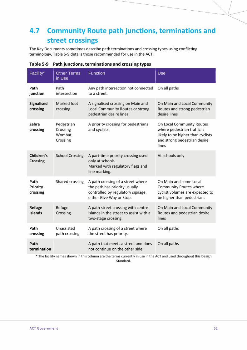
ACT Government 52
4.7 Community Route path junctions, terminations and street crossings
The Key Documents sometimes describe path terminations and crossing types using conflicting terminology, Table 5-9 details those recommended for use in the ACT.
Table 5-9 Path junctions, terminations and crossing types
Facility* Other Terms in Use
Function Use
Path junction
Path intersection
Any path intersection not connected to a street.
On all paths
Signalised crossing
Marked foot crossing
A signalised crossing on Main and Local Community Routes or strong pedestrian desire lines.
On Main and Local Community Routes and strong pedestrian desire lines
Zebra crossing
Pedestrian Crossing Wombat Crossing
A priority crossing for pedestrians and cyclists.
On Local Community Routes where pedestrian traffic is likely to be higher than cyclists and strong pedestrian desire lines
Children’s Crossing
School Crossing A part-time priority crossing used only at schools. Marked with regulatory flags and line marking.
At schools only
Path Priority crossing
Shared crossing A path crossing of a street where the path has priority usually controlled by regulatory signage, either Give Way or Stop.
On Main and some Local Community Routes where cyclist volumes are expected to be higher than pedestrians
Refuge Islands
Refuge Crossing
A path street crossing with centre islands in the street to assist with a two-stage crossing.
On Main and Local Community Routes and pedestrian desire lines
Path crossing
Unassisted path crossing
A path crossing of a street where the street has priority.
On all paths
Path termination
A path that meets a street and does not continue on the other side.
On all paths
* The facility names shown in this column are the terms currently in use in the ACT and used throughout this Design Standard.

ACT Government 53
4.7.1 Path junctions Estate Development and Retrofit
Path junctions on Main and Local Community Routes should be designed and linemarked in accordance with AGRD06A Section 6.4 with line types as detailed on ACTSD-3501. Directional signage is to be installed as per Section 4.10 and the examples shown in ACTSD-0590 to 0595.
4.7.2 Path crossings and terminations with streets – general Estate Development and Retrofit
Where a path on a Community Route intersects with the road network and continues on the other side of the street, it is defined as a path crossing. Where the path does not continue across the street it is referred to as a path termination. Path treatments at crossings and terminations are similar, however, at a crossing the designer should always consider the through movement for path users across the street in addition to the layout and design issues common to both facility types.
Under the Australian Roads Rules a path is terminated when it meets a street, and cyclists and pedestrians are required to give way to traffic before entering or crossing the street, unless signed otherwise.
AGRD06A identifies two objectives in the design of path crossings and termination treatments:
> Warning path users of the path’s termination at, or the street crossing, and > Restricting access to the path by unauthorised vehicles.
It is not acceptable practice in the ACT to combine these two objectives into a physical barrier or set of barriers. It is essential that these issues be considered separately. Path users should be given the highest priority in the overall design of the termination. Advice on the provision, design of any placement of vehicle access barriers is provided in Section 4.4.7.
Crossings and terminations will include appropriate path grades, wide kerb ramps, width adjustment for waiting, lighting, sight distance and signage for Main and Local Community Routes.
AGRD04 Sections 8 and 9 (pedestrian and cyclist street crossings), AGRD06A Section 7 (street crossings) and AGRD06A Section 7.2 (terminal treatments) provide general guidance on the design of these facilities.
Path and street approaches to crossings
Wherever possible, paths should be designed to warn cyclists and pedestrians to be alert to street conditions before negotiating any crossing. Paths should provide strong visual indication that there is a change in conditions ahead (refer to Section 4.4.8 for details on speed management methods on paths). To prevent shortcutting of paths near crossings or terminations, appropriate landscape treatments which do not interfere with sight lines may be installed. Maintenance requirements and sightline issues should always be taken into account when including landscaping treatments in path infrastructure.
Use of rails, bollards or other devices to prevent shortcutting may present a hazard to cyclists and are therefore not permitted.
Safe path design at crossings and terminations should ensure sight distances are adequate for all road and path users and that crossings are conveniently located. Parking should be prohibited for 20m on approach and 10m on departure of the path where it intersects with a street. Where kerb extensions or indented car parking is used, the no parking zone may be restricted to 1.5m either side of the outer edges of the kerb ramps if the foot of the kerb ramp is 2.0m from the kerb alignment of the adjacent parking.
ACT Government 54
Kerb ramps
Kerb ramps at path crossings, terminations and at intersections are to comply with ACTSD-0515 (for suburban land use areas), -0516 (for inner urban land use) and -0517 (for kerb ramps and slots in traffic islands). In Retrofit, kerb ramp details may be modified to suit constructability, existing infrastructure and aesthetic in accordance with the key design principles as detailed on the drawings.
It is important that kerb ramps be aligned in the direction of travel to guide vision-impaired pedestrians directly across the street and not out into the intersection, see ACTSD-0515 and -0516 for design details.
Particular attention should be paid to the design of any kerb ramps which are also on Accessible Pedestrian Routes. Tactile ground surface indicators (TGSI) should only be applied systematically to paths on APRs. Warning: Directional TGSIs should never be applied on kerb ramps because they can be a slip hazard. TGSIs are only used as per Section 5.2.
Cycle rest rails
Cycle rest rails are crossing aids for cyclists and also provide important visual cues to road users at crossing locations. Rail positioning and the use of the prescribed reflective tape arrangement is important to define the crossing location to approaching road users. To avoid confusion, cycle rest rails should never be provided where a cyclist has priority.
Cycle rest rails are to be provided on Main and Local Community Routes at:
> all non-priority road crossings; > link paths at roundabouts for diversion of on-road cyclists; and, > at traffic signal crossings.
Refer to ACTSD-0525 for details of types, reflective tape arrangement and appropriate positioning of cycle rest rails. Community Route directional and marker signage is installed on Main and Local Community Routes at all path crossings in accordance with Section 4.10.
4.7.3 Zebra crossings Estate Development and Retrofit
Basic requirements for the installation of Zebra Crossings are as per AS1742.10 Section 6.3. As Zebra Crossings in the ACT may be used by pedestrians and cyclists, the term “Zebra Crossing” is used in preference to the AS1742 and Austroads terminology – “Pedestrian Crossing” – to refer to its broader use in this jurisdiction.
This type of facility is designed and installed in accordance with ACTSD-3530 and -0522 and AGRD04 Section 8.2.3. As cyclists are permitted to approach a Zebra crossing at 10km/h, sightlines are modified from a Pedestrian Crossing and should be determined with consideration of vehicle approach speed. ACTSD-0522 provides guidance on sightlines required for various vehicle approach speeds to define the visibility splay for Zebra crossings where parking is not permitted, and visual obstructions are to be minimised.
Zebra Crossings are suitable for use on Local Community Routes and some Main Community Routes with high to moderate pedestrian usage where it is important to maintain continuous route priority. This includes use at uncontrolled or signalised intersections with slip lane crossings and mid-block crossings. They may also be installed for safety purposes and to service major community facilities subject to the approval of the Road Authority.
Zebra crossings are generally installed on pavement platforms at intersections and mid-block in Estate Development. Platforms are generally to be a red colour through use of red oxide in the concrete, refer to

ACT Government 55
Coloured surfacing in Section 2.3.2 for colour details. Details of Zebra Crossing arrangements at intersections for Main and Local Community Routes in Estate Development are shown on ACTSD-0528. Details on the construction and layout of raised pavement platforms are provided on ACTSD-3531 and -3532.
Refer to MIS14 for crossing lighting requirements, the path approaches are to be lit to the extent of the visibility splay as shown on ACTSD-0522.
Risk minimisation
As cyclists and pedestrians have different operating characteristics, warning signage and physical treatments may be applied in different situations in response to user behaviour and site issues. Table 5-10 lists a three-level application of warning signage and physical measures to reduce operational risks each Zebra crossing. The application of these measures is further detailed in ACTSD-0523.
Table 5-10 Priority crossing risk minimisation design requirements
Level
Risks addressed Recommended installation
1a Basic requirement for Zebra and Path Priority crossing in retrofit
Facility design and installation as per AS1742.10 with additional ACT design requirements as detailed in ACTSD-3530 and ACTSD-0522.
1b Basic requirement for Zebra and Path Priority crossing in Estate Development
Facility design and installation as per AS1742.10 with additional ACT design requirements (raised pavement platform and path approach deflection offsets) as detailed in ACTSD-3530, -3531, -3532, 0521 and -0522.
2a High incidence of excessive approach speeds by cyclists
Install temporary approach warning signage as detailed in ACTSD-0523.
2b Persistent incidence of high approach speeds by cyclists
Install permanent path approach warning signage and permanent pavement markings as detailed in ACTSD-0523 and -3524
2c Persistent incidence of high approach speeds by cyclists with an increased level of serious incidents at site
Install raised pavement platform on crossing as detailed in ACTSD-3531, warning signs and pavement markings on both path approaches to crossing as detailed in ACTSD-0523 and ACTSD-3524
3a High incidence of excessive approach speeds by motorists
Install raised pavement platform on crossing as detailed in ACTSD-3531
3b Continuing and persistent incidence of high approach speeds by motorists with an increased level of serious incidents at site
Install raised pavement platform on crossing as detailed in ACTSD-3531, speed cushions or asphaltic concrete raised pavement platforms on both street approaches to crossing as detailed in MIS13.3.19 and ACTSD-3533. Also, pavement markings as detailed in ACTSD-0523 and ACTSD-3524
Retrofit only
Zebra crossings may be installed at-grade at intersections and mid-block in retrofit and details of crossing arrangements at intersections are provided on ACTSD-0529.

ACT Government 56
4.7.4 Children’s crossings Estate Development and Retrofit
A Children’s Crossing is a part-time facility operating only when a “Children Crossing” flag is displayed. It is essential that schools or the operators of Children’s Crossings remove flags when crossings are not in use.
Design details can be found in AS1742.10, ACTSD-3530 and TMSPGS. The details shown in ACTSD-3530 take precedence over other guidelines for the layout, linemarking and signing of this facility. This crossing gives pedestrian priority over vehicles along desire lines close to school yard entrances. Care should be taken when installing crossings on paths directly adjacent to the road pavement to ensure flags do not obscure children waiting to cross from approaching motorists or represent a hazard to path users. Children’s Crossings can be implemented at all schools including pre-schools and colleges. Further information on the application of Children’s Crossings can be found in TMSPGS.
4.7.5 Path Priority crossings Estate Development and Retrofit
Path Priority crossings should always be considered on Main Community Routes to provide improved route continuity and path user amenity and safety. Mid-block Path Priority crossings are designed in accordance with ACTSD-0521, -0528 and -0529. Additional guidance can be found in AGRD04 Section 9.3. Path Priority crossings are used on Main and Local Community Routes for mid-block priority crossings of local access and minor collector streets where traffic volume on the path exceeds the street volume.
The preferred treatment for a Path Priority crossing is a full raised platform though site considerations (cross-fall and drainage) may require variations in platform design. Platforms are generally to be a red colour through use of red oxide in the concrete, refer to Coloured surfacing in Section 2.3.2 for colour details. The mid-block Path Priority crossing in Figure 5-7 shows a four-way platform installed at the crossing in Retrofit. See ACTSD-3532 for platform details.
Figure 5-7 Path Priority crossing of a local access street Location: Lyneham, ACT. Inset detail shows crossing area speed hump and ACT linemarking detail.

ACT Government 57
Other calming devices may be used in conjunction with a Path Priority crossing to slow traffic in advance of the crossing on both the roadway and the path approaches. The risk management process listed in Table 5-10 and as illustrated on ACTSD-0523 may be applied to Path Priority crossings to improve safety.
A ‘bent-out’ Path Priority crossing, is used for crossing intersecting streets when the route is located in the verge of a continuing street. See ACTSD-0528 and -0529 for details. The use of Path Priority crossings on slip lanes is shown on ACTSD-0520.
A Zebra crossing is preferred on Main Community Route crossings where the volume of cyclists is considered low and with the approval of the Road Authority.
Refer to MIS14 for crossing lighting requirements, the path approaches are to be lit to the extent of the visibility splay as shown on ACTSD-0522.
Retrofit only
In Retrofit the Path Priority crossing may be installed at grade as shown on ACTSD-0529. ACTSD-0520 shows the arrangement for use of the crossing at slip lanes, carpark entries and local access streets in Retrofit in a Suburban land use context. Use of red coloured pavement treatment
Bicycle-only Path Priority crossings - are always considered on sections of Main or Local Community Routes where bicycle-only paths are provided, refer to Section 4.7.5 for details.
4.7.6 Signalised intersections, crossings and slip lane treatments Estate Development and Retrofit
An intersection with bicycle or pedestrian signals may reduce stress and delays for Community Route users and discourage illegal and unsafe crossing manoeuvres. At signalised intersections in the ACT it is permissible for cyclists to use pedestrian signalised crosswalks without special bicycle signal lanterns. By law cyclists must obey the pedestrian lanterns and give way to pedestrians on the crosswalk.
At signalised road junctions, potential conflicts should be regulated by the layout, marking and signal phasing of the intersection. Separate three aspect signals are used on bicycle-only paths to increase safety by indicating separate bicycle movements to avoid conflicting vehicle movements. Consideration should be given to a separate turning phase or ‘head start’ for bicycle-only path turnings.
In-ground detector loops for cyclists should be installed on bicycle-only path facilities. Diamond pavement markings indicate the optimum waiting position for activation loops.
Traffic signal phasing should not impose a time penalty on Main or Local Community Routes as this discourages the use of the facilities and degrades their value for transportation. At signalised crossings on these routes, signal phasing timing is optimised to provide a high level of service to the route crossing. In off-peak times where traffic in the intersection roadways is minimal, call-up times for are reduced to a minimum.
Signal posts, cycle rest rails and activation buttons (where used) are located to provide clear, safe access to the crossing approaches and storage at the intersection. Cycle rest rails are located close to activation buttons.
On identified Main Community and Local Community Routes Path Priority crossings are installed across slip lanes which link to signalised crossings. Generally, these will be Path Priority crossings on Main Community Routes and Zebra crossings (see ACTSD-0520) on Local Community Routes. Alternatively, in inner urban land use contexts the slip lane may be removed. Refer to Section 4.7 for details on crossing types.

ACT Government 58
Estate Development and Retrofit
Signalised pedestrian/cyclist crossings (also known as marked foot crossings) are designed and linemarked in accordance with AGRD04 Appendices and ACTSD-3501. If the crossing is located close to a school refer to TMSPGS for design details.
Signalised pedestrian/cyclist crossings may be considered where peak traffic volumes on the road exceed 1,000 vehicles per hour and peak path usage is greater than 100 users per hour. On signalised crossings of Main and Local Community Routes, the crossing width is 3.0m – see ACTSD-3501. Signalised crossings should only be installed in appropriate locations and their function can be co-ordinated with other sets of traffic signals. Paths are to be fitted with advance detector loops at signalised crossings in addition to activation buttons to improve the level of service for path users. Refer to ACTSD-3911 and -3912.
4.7.7 Bicycle-only facilities at intersections - Signalised Estate Development and Retrofit
The Key Documents do not provide detailed guidance for bicycle-only paths at signalised intersections. Refer to ACTSD-0560 for detailed advice on preferred intersection designs for two-way bicycle-only paths and ACTSD-0561 for one-way paired bicycle-only paths. Protected intersection designs are preferred when bicycle-only paths are used at signalised intersections – see Figure 5-8.
Refer to MIS 13 Traffic Control Devices and ACTSD-3540 for details of linemarking at signalised intersections.
Figure 5-8 Two-way bicycle-only paths at a signalised intersection Location: Bells Creek, Queensland, Photo courtesy of Queensland Department of Transport and Main Roads.
On bicycle-only path approaches to signalised intersections, detection loops should be placed in the path surface at the holding line and in advance of intersections to minimise delay time for cyclists and to allow them to proceed through on the green phase. See US NACTO design manual Urban Bikeway Design Guide, Second Edition 2014 (Signals section) for information on location of path surface detection loops. Adjacent paths are physically separated from bicycle-only paths through the intersection regardless of the level/grade of each facility.
ACT Government 59
The length of the marked approach waiting lane for bicycle-only paths is 4.0m (two bicycle lengths). The width of this lane at the holding line depends on the volume of bicycle traffic using the intersection. It is important to allow a generous amount of space at approaches to intersections (wider than the minimum recommended one-way bicycle-only path width of 2.0m with kerbs, 1.5m without kerbs) due to the extra space often needed by cyclists on starting up.
At three-way signalised intersections and intersections with high volumes of left turning vehicles, a separate bicycle crossing light may be used which allows cyclists to cross the stop line when green independent of the traffic light in accordance with the ACT Traffic Regulations. This allows prioritised crossing independent of road traffic on three-way signalised intersections and cyclists an advance start prior to vehicles turning left at other signalised intersections.
4.7.8 Bicycle-only facilities at intersections - Unsignalised Estate Development and Retrofit
Bicycle-only paths on Main and Local Community Routes at unsignalised side street intersections use a bent-out treatment at major crossings with Path Priority or Zebra crossings, see ACTSD-0505 to -0509 and AGRD04 Section 9.3 for design details.
At minor side streets a continuous verge treatment shown in ACTSD-0505 and -0506 is used – see Section 4.7.12 for details.
Refer to related advice in Section 0 for information on intersection facilities for On-Road Cycling Routes.
Path Priority crossings associated with bicycle-only paths are usually planned and executed alongside Zebra crossings. It is common practice to place the Path Priority crossing between the motor vehicle lanes and the Zebra crossing. Conflicts between cyclists, pedestrians and motor vehicles should be minimised by the intersection design and Path Priority crossings on two-way bicycle-only paths are always on raised pavement platforms in Estate Development.
One-way paired bicycle-only paths may use a bent-in treatment in lower speed inner urban land use contexts where the bicycle-only path (at verge grade) is brought down to road grade on approach to the intersection and proceeds through the side street intersection as a bicycle lane. This treatment is shown in ACTSD-0506 and in AGRD04 Figure 9.11. A bent-out treatment is preferred In suburban land use contexts when a bicycle-only path is in a wider verge and located away from the kerb as shown on ACTSD-0507.
Straight Path Priority crossings at verge grade can be used on one-way bicycle-only paths on side street crossings and located adjacent to a Zebra crossing as shown in ACTSD-0506. A continuous verge treatment may be used to provide path priority on minor street crossings as shown on ACTSD-0506, also refer to Section 4.7.12 for more details.
Two-way bicycle-only paths at side street intersections use a bent-out treatment at crossings of collectors and higher volume local access streets, see ACTSD-0505 and AGRD04 Section 9.6.3 for design details. Continuous verge treatments may also be used to provide path priority on minor street crossings as shown on ACTSD-0505, also refer to Section 4.7.12 for more details.
Where bicycle-only Path Priority crossings are provided at side streets, due to the complex nature of this facility, Stop signs may be used in place of Give Way signs and a raised pavement platform installed in Retrofit when Stop signs are required.

ACT Government 60
Where the path does not have priority over the roadway cycle rest rails can provide a visual marker of the crossing location and propping assistance to queuing cyclists. Cycle rest rails are only to be placed on crossings where the roadway has priority, placed on the left side of the path approach and must not impede pedestrian or cycle movement through the intersection. Placement in the centre of the path is not permitted. Paths and the areas between path and road should be kept free of all obstructions to improve visibility, manoeuvrability and maximum storage space at the intersection.
Retrofit only
Two-way bicycle-only Path Priority crossings may be installed at grade in Retrofit only, refer to ACTSD-0505 for details.
4.7.9 Roundabouts Estate Development and Retrofit
The operating requirements and network needs of pedestrians and cyclists should always be considered in the design of roundabouts. While roundabouts can greatly assist the flow of motorised traffic flow, on higher-speed, high-trafficked roads they generally deliver a poor outcome for pedestrians and cyclists and tend to discourage active travel. Other intersection treatments should always be considered ahead of roundabouts where Community Routes are present.
A discussion of treatments and design solutions applicable to roundabouts is provided in AGRD04B Part 5. This section supplements or replaces treatments shown in that document in response to ACT conditions and refers to Community Route and On-Road Cycling Route treatments (refer to Section 7.2.5 for on-road cycling routes at roundabouts).
ACTSD-0551 to 0554 provide guidance on the design of treatments for pedestrians and cyclists at roundabouts, based on ACT road hierarchy, speed environment and the function of the intersecting streets. Design of roundabouts includes provision for potentially faster-moving on-road cyclists according to the hierarchy of the On-Road Cycling Route identified in the ATRA.
Link paths to allow on-road cyclists to connect safely with the off-road Community Route facilities are to be provided. Treatments should consider the potential conflicts between faster-moving cyclists exiting from the roadway with users of Community Route facilities.
Supplementary guidance on roundabout design can be obtained from the Queensland Transport and Main Roads (TMR) Technical Note Providing for Cyclists at Roundabouts, (see TMR website in Technical Publications/Technical Notes). Cities and towns within this jurisdiction have a similar urban form, road designs and rules to those in the ACT.
a) Issues relating to Community Routes at all roundabouts
Traffic signals are preferred on higher speed / traffic volume roads to improve access for pedestrians and cyclists. Where there may be a strong preference for introducing a roundabout, provision of grade separated access for pedestrians and cyclists should be considered. If surface paths are to be provided, consideration should be given to limiting the approach and departure speed environment especially through crossing points. This would normally require implementation of physical measures to reduce vehicle speeds, such as the geometry of the roundabout etc. Any speed reduction measures at the roundabout would require coordination with speed limits along approach roads.
Priority crossings may be installed on Main and Local Community Routes that cross the roadway adjacent to a roundabout similar to the treatments shown for use on Priority crossings of side streets. Any Priority crossing installation adjacent to a roundabout must consider the approach and departure speeds for the particular roundabout and a staged crossing provided in lieu of a Priority crossing if speed and safety issues cannot be adequately addressed through the installation of calming measures .

ACT Government 61
Where cycle rest rail turn-outs are used at Community Route crossings adjacent to roundabout exits, a Safe Systems approach should be followed in the appropriate siting of the rest rails to minimise any possible collision impacts by motor vehicles. To minimise the risk of vehicle collisions on high speed roundabout exits, consideration should be given to the installation of single post rest rails.
b) Issues relating to roundabouts with speeds of 50km/h or less
When the cycling component of Main and Local Community Routes is located on-road as an Active Travel Street, single-lane roundabouts may be used. Separate and parallel path provision should always be provided along these streets (and around roundabouts) for pedestrians and cyclists preferring to ride on paths. Refer to ACTSD-0551 for details of this type of roundabout.
c) Issues relating to roundabouts with speeds of above 50km/h
On-road facilities for Main and Local Community Routes are not provided in this type of roundabout. paths will be provided for Community Route users and include link paths to connect any on-road facilities provided as part of On-Road Cycling Routes. Priority crossings may be provided across side streets for Main and Local Community Routes at roundabouts. Bypass paths should be provided through three-legged roundabouts. Refer to ACTSD-0552 and -0553 for details on roundabouts with speeds above 50km/h.
Higher speed and traffic volume roundabouts may present significant risks to pedestrians and off-road cyclists using Community Route facilities As part of the planning and design process, practitioners should consider the following:
> Reducing the approach and departure speeds and number of approach or circulating lanes through revised geometry or other modifications to improve the integration and safe travel of pedestrians and cyclists across the approaches and departures to the roundabout.
> Installing a standard signalised intersection to improve access both for pedestrians and on-road and off-road cyclists.
> Installing grade separation (underpasses or overpasses). > Reducing the speed environment (and speed limit) on roads feeding an intersection to improve safety
and access for cyclists (and pedestrians) at uncontrolled intersections on roundabout feeder roads. This normally requires physical measures to reduce the speed environment and should be coordinated with the speed limits along the length of the road.
4.7.10 Refuge islands Estate Development and Retrofit
Refuge islands assist pedestrians and cyclists to cross streets by breaking the crossing into two parts thus reducing crossing difficulty and reducing crossing delay. Refuge islands are designed, signed and linemarked in accordance with ACTSD-3504 and with additional advice from AGRD04 Appendices. Signage assembly details for refuge islands are in ACTSD-3611.
In Estate Development the width of refuge islands is 3.0m (2.0m minimum width in Retrofit) along the line of the crossing to cater for the full range of bicycle types. The width of the kerb slot is to be a 3.0m on Main and Local Community Routes and 2.0m in Retrofit and at all other crossings.
On higher-use routes, it may be necessary to increase the width of the crossing path to provide greater storage capacity. The width of both kerb ramps and the path between the islands should always match the width of the path connecting to the facility.
Refuges may be required on wide streets with higher traffic volumes (eg. major collectors). The need for a refuge is determined on a case by case basis, addressing issues such as sight distances, vehicle speeds,

ACT Government 62
proximity to shops, primary schools etc. which will determine if a two-stage crossing is warranted. Before considering the installation of refuge islands, other measures to reduce the crossing distance such as kerb extensions from the footpath, and/or local area traffic management (LATM) treatments to reduced vehicle speeds, should be considered.
Refuges and any associated kerb extensions should not be used where resultant narrowing of the road lanes would create a squeeze point for on-road cyclists. Refer to Section 7.1.8 for further details.
Refuges on narrow streets are primarily useful to pedestrians – particularly the elderly. Cyclists can cross streets and roads more quickly and easily in one movement so narrowing the street by use of kerb extensions on low volume streets may be a more useful treatment for all users than the installation of refuge islands. Refuge islands are generally inappropriate on local access streets with low traffic volumes and speeds.
Refuge islands at roundabouts should provide refuge within the island for pedestrians and cyclists (except on local access streets). The crossing should be located 6m (or one car length) behind the hold line. This latter condition may not be possible in minor or mini roundabouts.
Care is to be taken in the installation of ‘target boards’ on refuge islands in areas near primary schools where the specified height above the kerb slot pavement level is not to exceed 700mm, refer ACTSD-3611, as these devices can obscure children from the view of approaching road users.
4.7.11 Path crossings and terminations – uncontrolled Estate Development and Retrofit
Uncontrolled path crossings and terminations are designed in accordance with the general installation requirements for crossings and terminations listed in Section 4.7.2, AGRD06A Section 7 and AGRD04 Appendices. Kerb ramps and the path/street interface are designed in accordance with ACTSD-0515 and -0516 and AGRD04 Figure 9.1.
Where a trunk path meets a street without a kerb, path give way linemarking and signage is used to provide additional definition to clearly mark the street crossing or path termination.
Kerb ramps at path crossings and intersections should be located to minimise deviations from the desire line, and also to minimise crossing distances.Additional design requirements for uncontrolled street crossings of Community Routes and Equestrian Routes is provided in Section 6.2.2.
4.7.12 Continuous verges Pedestrian and cyclist prioritisation is desirable in inner urban land use such as town and group centres, shopping precincts, around public transport hubs and entertainment venues. It may also be desirable in higher density residential areas to encourage pedestrian/cyclist activity, maintain route continuity and reduce real and perceived motor vehicle dominance. Where vehicle traffic volumes are relatively low (<1,000vpd), potential conflicts are also relatively low and regulatory pedestrian prioritisation treatments may not be warranted. In such locations, pedestrian/cyclist priority may be provided by continuous verge treatments which are a continuation of the path/verge parallel with the main street, at verge grade across side street intersections – see Figure 5-6.
Continuous verge treatments are located within the road related area and use platform ramps to raise the roadway to verge level, area paving (or continuous paths at verge grade) supported by give way linemarking and active travel direction indicators to further define the facility. In situations where traffic volumes exceed 1,000vpd, regulatory crossings (Path Priority or Zebra crossings) are installed. Layout and signage details for continuous verge treatments on Main and Local Community Routes are detailed in ACTSD-0505 and -0506 for bicycle-only paths with adjacent (shared) paths and ACTSD-0528 for (shared) paths.

ACT Government 63
Estate Development and Retrofit
Continuous verge treatments are used across low volume / low speed side streets or major driveway crossings to encourage active travel and to improve network continuity. Area paving of a contrasting colour to the crossing street and adjacent paths is used (as shown in ACTSD-0505, -0506, -0528 and Figure 5-6) for inner urban land use. In suburban land use, area paving is not required, and paths are maintained through the continuous verge area.
In suburban land use, on trunk paths shared by pedestrians and cyclists on Main and Local Community Routes, red pavement colour is used in the continuous verge area if traffic on the side street is >100vpd. Green pavement colour on bicycle-only paths through continuous verges is used if traffic in the side street is >100vpd. The (shared) path adjacent to the bicycle-only path should be a contrasting colour through the continuous verge with red colour required when traffic i in the side street is >100vpd. Refer to Coloured surfacing in Section 2.3.2 for colour details.
High volume trunk path crossings across minor side streets without continuous verges use street-grade Zebra crossings.
4.7.13 Driveway crossings across Community Routes A driveway is a defined area used by motor vehicles travelling between a public street or road and a property adjacent or near to the road. As a driveway is always located in the verge it is always essential that they are designed to look like a driveway and not a street or road.
Estate development
Where a path on a Main or Local Community Route is located in the verge, the verge and adjacent blocks are to be designed so that there are no driveway crossings across the path.
Retrofit only
Paths on Main and Local Community Routes retrofitted to existing streets are laid out to ensure maximum sightline vision on all crossing driveways. Where possible the path should be located away from obscuring fence lines and street poles in the centre of the verge area.
Where existing driveways cross Main and Local Community Route facilities warning linemarking and surface colour is applied where the path and driveway intersects to warn users of a possible conflict zone. The treatment to be applied is determined by the number of vehicle spaces to be accessed by the driveway and the treatment including the linemarking/surface colour is to be applied in strict accordance with ACTSD-0526 for bicycle-only paths and ACTSD-0527 for (shared) paths.
4.7.14 Path to roadway connections Estate Development and Retrofit
Link paths should be conveniently provided where possible for cyclists wishing to switch between paths on Community Routes and On-Road Cycling Routes. The transition type should be provided to suit on-road facilities in accordance with ACTSD-0510. See also Section 7.2.6 for details of link paths when used at roundabouts.

ACT Government 64
4.8 Facilities for Community Routes on streets 4.8.1 General Estate development
Facilities associated with Main and Local Community Routes for Estate Development are to be located in the verge or adjacent open space except on certain local access streets where the route may be located on-street either as an Active Travel Street, Shared Zone or Shared Space.
In inner urban land use contexts, provision for general cycling on the roadway should always be included when setting the carriageway width. This width should consider the particular traffic environment such as traffic-speed, traffic-volume, parking provision, active commercial vehicle traffic, frequent stopping and turning movements. Special attention should also be paid to design details for pavement surfacing, kerb radii and at crossings and intersections.
Retrofit only
In established areas where Main or Local Community Route facilities meeting Estate Development requirements cannot be installed, it may be necessary for an Active Travel Street, Shared Zone or Shared Space to be installed to provide route continuity as detailed below.
4.8.2 Active travel streets Estate Development and Retrofit
Active Travel Streets are low-speed, low-volume, traffic calmed streets optimised for bicycle travel on-road with improved adjacent path provision for pedestrians. The on-road cycling component of an Active Travel Street is called a “Bicycle Boulevard” – a type of mixed traffic facility which aims to create a bicycle-friendly street environment by the introduction of a package of LATM measures to reduce traffic volumes and traffic speeds to below 30km/h by design. In the ACT an Active Travel Street facility always includes measures to improve pedestrian safety and amenity along the Active Travel Street.
Active Travel Streets can be used for Main and Local Community Routes in both Estate Development and Retrofit situations (see below) and are particularly suited for retrofit use in inner urban land use contexts.
Active Travel Streets can be used to provide a more attractive and safer walking and cycling environment to arterial or major collector road corridors by utilising parallel local access streets with bicycle boulevard treatments and suitable path enhancements. This approach can also apply to minor collectors to minimise the risk of driveway crossings and interactions with busses when also a bus route.
Design examples and information on developing Active Travel Streets are provided in ACTSD-0512. Additional design information on Bicycle Boulevard treatments can be obtained from the US National Association of City Transportation Officials (NACTO) design manual Urban Bikeway Design Guide Second Edition 2014 (Bicycle Boulevards section).
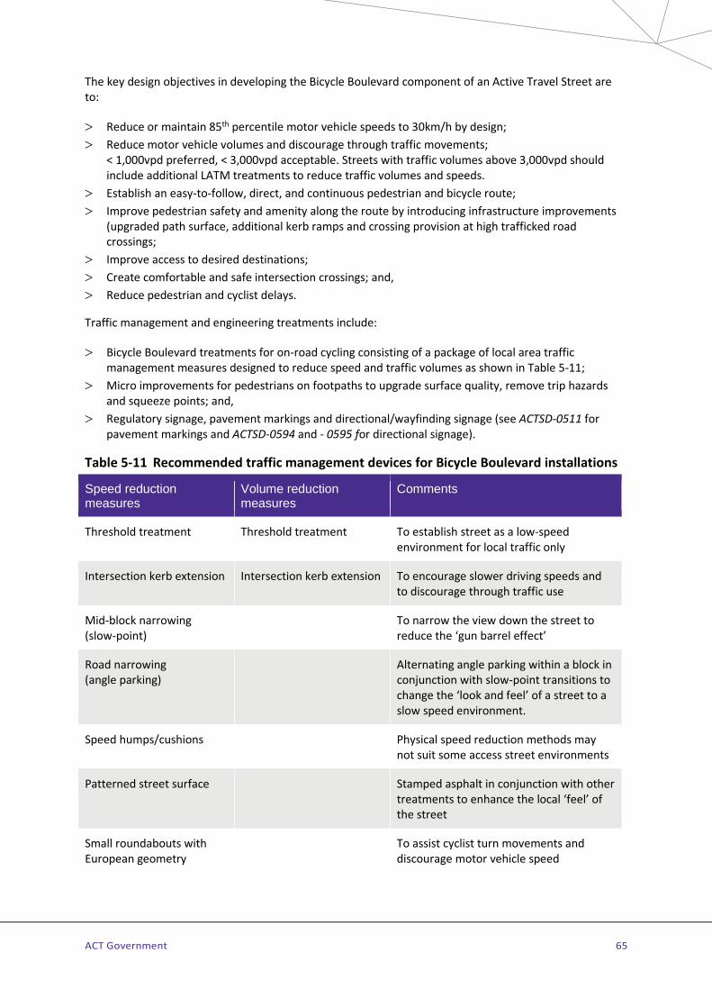
ACT Government 65
The key design objectives in developing the Bicycle Boulevard component of an Active Travel Street are to:
> Reduce or maintain 85th percentile motor vehicle speeds to 30km/h by design; > Reduce motor vehicle volumes and discourage through traffic movements;
< 1,000vpd preferred, < 3,000vpd acceptable. Streets with traffic volumes above 3,000vpd should include additional LATM treatments to reduce traffic volumes and speeds.
> Establish an easy-to-follow, direct, and continuous pedestrian and bicycle route; > Improve pedestrian safety and amenity along the route by introducing infrastructure improvements
(upgraded path surface, additional kerb ramps and crossing provision at high trafficked road crossings;
> Improve access to desired destinations; > Create comfortable and safe intersection crossings; and, > Reduce pedestrian and cyclist delays.
Traffic management and engineering treatments include:
> Bicycle Boulevard treatments for on-road cycling consisting of a package of local area traffic management measures designed to reduce speed and traffic volumes as shown in Table 5-11;
> Micro improvements for pedestrians on footpaths to upgrade surface quality, remove trip hazards and squeeze points; and,
> Regulatory signage, pavement markings and directional/wayfinding signage (see ACTSD-0511 for pavement markings and ACTSD-0594 and - 0595 for directional signage).
Table 5-11 Recommended traffic management devices for Bicycle Boulevard installations
Speed reduction measures
Volume reduction measures
Comments
Threshold treatment Threshold treatment To establish street as a low-speed environment for local traffic only
Intersection kerb extension Intersection kerb extension To encourage slower driving speeds and to discourage through traffic use
Mid-block narrowing (slow-point)
To narrow the view down the street to reduce the ‘gun barrel effect’
Road narrowing (angle parking)
Alternating angle parking within a block in conjunction with slow-point transitions to change the ‘look and feel’ of a street to a slow speed environment.
Speed humps/cushions Physical speed reduction methods may not suit some access street environments
Patterned street surface Stamped asphalt in conjunction with other treatments to enhance the local ‘feel’ of the street
Small roundabouts with European geometry
To assist cyclist turn movements and discourage motor vehicle speed
ACT Government 66
Speed reduction measures
Volume reduction measures
Comments
Traffic diversion Angled traffic diversion with through access for cyclists
Give way signs Breaks the through-route momentum for motor vehicles. A minor inconvenience for cyclists
Partial street closure Provides only one way access for motor vehicles but two way access for bicycles
Full street closure Landscaped closure with through access for cyclists and pedestrians only.
Modified t-intersection Realigns the priority of the intersection flow to favour cyclist movements
For details of Bicycle Boulevard implementation examples and pavement marking layouts indicating on-street cycle travel and wayfinding for Main or Local Community Routes refer to ACTSD-0512 and ACTSD-0511 and -3523 for details of the pavement markings for use on roadways.
4.8.3 Shared zones Retrofit only
A Shared Zone is a road or cluster of roads where the road space is shared safely by motor vehicle drivers, cyclists and pedestrians. The facility is defined in AS1742.10, AGTM08 and the Transport for NSW policy and guidelines document SS/12/01 – Shared Zones. The maximum speed limit is usually 10 km/h or as determined by Road Authority assessment.
Unlike Shared Space, a broader concept involving other urban design elements, a Shared Zone is usually installed on an inner urban street where there are high volumes of pedestrians and pedestrian access is paramount but access for other modes needs to be maintained.
A Shared Zone may be at verge level and free of centre linemarking and kerb and guttering to provide a strong visual message that pedestrians and vehicles operate on equal terms. Drivers and riders must give way to pedestrians at all times. Vehicles can only stop in a Shared Zone if they obey the parking signs and park in marked bays, if provided.
4.8.4 Shared space Estate Development and Retrofit
Shared Space is a concept of road design where a thoroughfare appears less like a road and more like a plaza – an open space engineered and landscaped to be shared more equitably and safely by pedestrians, cyclists and motor vehicles. A shared space has a very different visual and physical ‘feel’ from the traditional road where factors such as grade separation of road and paths and defined crossings encourage the dominance of the motor vehicle.
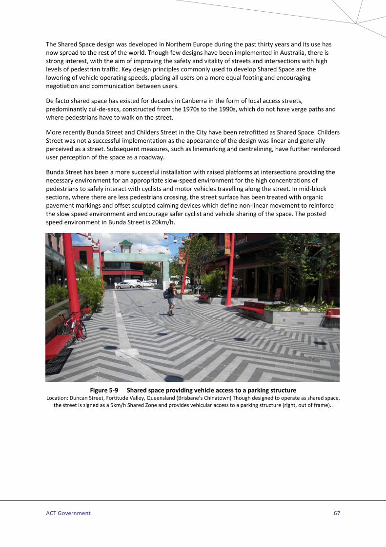
ACT Government 67
The Shared Space design was developed in Northern Europe during the past thirty years and its use has now spread to the rest of the world. Though few designs have been implemented in Australia, there is strong interest, with the aim of improving the safety and vitality of streets and intersections with high levels of pedestrian traffic. Key design principles commonly used to develop Shared Space are the lowering of vehicle operating speeds, placing all users on a more equal footing and encouraging negotiation and communication between users.
De facto shared space has existed for decades in Canberra in the form of local access streets, predominantly cul-de-sacs, constructed from the 1970s to the 1990s, which do not have verge paths and where pedestrians have to walk on the street.
More recently Bunda Street and Childers Street in the City have been retrofitted as Shared Space. Childers Street was not a successful implementation as the appearance of the design was linear and generally perceived as a street. Subsequent measures, such as linemarking and centrelining, have further reinforced user perception of the space as a roadway.
Bunda Street has been a more successful installation with raised platforms at intersections providing the necessary environment for an appropriate slow-speed environment for the high concentrations of pedestrians to safely interact with cyclists and motor vehicles travelling along the street. In mid-block sections, where there are less pedestrians crossing, the street surface has been treated with organic pavement markings and offset sculpted calming devices which define non-linear movement to reinforce the slow speed environment and encourage safer cyclist and vehicle sharing of the space. The posted speed environment in Bunda Street is 20km/h.
Figure 5-9 Shared space providing vehicle access to a parking structure Location: Duncan Street, Fortitude Valley, Queensland (Brisbane’s Chinatown) Though designed to operate as shared space,
the street is signed as a 5km/h Shared Zone and provides vehicular access to a parking structure (right, out of frame)..

ACT Government 68
Though some regulatory measures may be required (such as a reduced speed limit), Shared Space differs from Shared Zones by using urban design elements to reinforce the primacy of pedestrians and other active modes within a redesigned streetscape. Successful implementation of Shared Space is achieved by area paving, landscaping, discrete location of street furniture and revised drainage to minimise the visual impact of linear kerb and guttering. Signs and markings are minimal and when used should be in keeping with the visual effect of the streetscape (ie: parking bays if present, should be defined by contrasting paving rather than paint. Treatments including along car parking edges should not provide linemarking or linear patterning leading to a perception of a roadway. It is important that the design does not appear to give priority to vehicles, for this would undermine the principle of shared space. Organic or broken patterns are preferred to promote this requirement.
In inner urban land use contexts, the movement and place function of the street should be carefully considered . All streets should provide for good active travel connectivity and for streets that require minimal vehicle movements design should reflect the street as a place for vehicles and favour the movement of active travel. Shared Space may be used on all levels of the Community Route hierarchy with the design of treatments set by whether the street forms part of a Main or Local Community Route and the type of the required vehicle traffic through the space.
Shared space is a design process which functions within the existing road rules and guidelines paying particular attention to the techniques and processes detailed in AGRD03, AGRD4A and AGTM08. The posted speed limit for shared spaces is generally 20km/h in the ACT. Design approval for shared space treatments requires the approval of the Road Authority. Further advice on the design philosophy and principles of shared space can be obtained in the UK Department for Transport Local Transport Note 1/11, October 2011. Information on the design, development and operation of existing Canberra shared space projects (eg: Bunda Street and Childers Street) should be sought before commencing detail designs.
4.8.5 Community Route facilities on-streets with narrow verge paths Retrofit only
The development of Main and Local Community Routes through established areas aims to provide safe and comfortable active travel for a wide range of walkers and cyclists (from ages 8 to 80). This is usually done through the provision of paths separated from motor vehicle traffic either on street verges or through public open space.
In some established areas, Community Routes may be located along streets with narrow verges and paths unsuitable for shared use.
When a path for both user groups cannot be provided to meet the requirements of Table 5-4, cycling provision may be provided on streets. This should generally comply with the mixed traffic, low-speed, low-volume cycling environment guidance in Section 4.8.2, ACTSD-0512 and in Austroads.
Path facilities for pedestrians should always be provided when the cycling component of Main and Local Community Routes is located on-road in mixed-traffic streets. It is essential to consider vulnerable users such as school children and elderly riders who may not feel comfortable riding on the roadway in any circumstance. When upgrading street pavements in these locations, upgrades of adjacent footpaths should be carried out at the same time.
ACT Government 69
4.8.6 Community Route facilities on-streets without verge paths Retrofit only
For Main and Local Community Routes through established areas the achievement of a continuous, direct and easy-graded route using as much available greenspace as available is often not possible without utilising short connecting sections of local access streets. In many established areas these streets are narrow and have not been designed or built with verge paths. Such streets generally have low-traffic volumes and slow traffic speeds and are usually older ACT Code legacy access streets with speed limit ≤50km/h.
When a path for both user groups cannot be provided to meet the facilities and conditions listed in Table 5-4, cycling and walking provision may be provided on the street as detailed in ACTSD-0513 and -0514. This should generally comply with the mixed traffic, low-speed, low-volume cycling environment guidance for the facility described as an Active Travel Street as detailed in Section 4.8.2 and in Austroads.
4.9 Integration with public transport – bus and light rail stops
Estate Development and Retrofit
Facilities on Community Routes should be well connected to public transport stops and amenities to ensure effective mode integration. Where paths for Community Routes are located in the verge adjacent to bus and light rail stops they should provide a continuous path for pedestrians and cyclists clear of waiting passengers.
Paths on Main or Local Community Routes paralleling roads should be designed to pass the bus or light rail stop to the rear of the pad or shelter structure; the through path should be aligned to allow adequate sight distance with allowance for any shelter associated with the public transport stop. Zebra crossings are not generally provided on access paths to public transport stops across bicycle-only paths.
Access to public transport stops is provided for pedestrians and cyclists in accordance with Standard Drawings ACTSD-0530 to -0532 and the NSW Bicycle Guidelines Section 5.1.3. Acceptable grades for DDA access especially in Retrofit situations should also be carefully considered.
Bicycle parking facilities should be provided at major light rail and bus stops including the provision of transport smart card operated bicycle lock-up cages at high volume stops and interchanges.

ACT Government 70
4.10 Directional signage for Community Routes 4.10.1 Planning for directional signs Estate Development and Retrofit
The principles of Community Route directional signage are based on the hierarchy of active travel transportation routes and destinations. The Active Travel Route Alignments (ATRA), available through the ATIPT shows Principal, Main and Local Community Routes, all of which are to be signed over time and maintained. The ATIPT also provides access to the destination names (focal point names) to be used consistently throughout the sign system.
Unless approved by the Road Authority, directional signage for pedestrians and cyclists is restricted to Principal, Main and Local Community Routes.
Principal Community Routes (PCRs) are a branded subset of Main Community Routes providing the most direct and rapid connections between town centres and some other key active travel destinations. Main Community Routes connect PCRs to group and employment centres and Local Community Routes provide linkages to local centres and major community destinations.
Main Community Route directional signs serve both primary destinations (City, Town Centres and Queanbeyan) and secondary destinations (predominately Group Centres). Local Community Route signage serves local destinations such as local centres and major community destinations. Principal Community Route signage provides branding for the identified Main Community Routes.
Community Route directional signs are to be installed at the following locations:
Key decision points - A key decision point is defined as the intersection of the following:
> two or more Principal, Main or Local Community Routes > a direct access to a local destination that may not be on a Principal, Main or Local Community Route. > main access points to destinations, generally the entrance to destinations such as shopping
areas/centres at town, group or local centres, hospitals, tertiary institutions and district parks and playing fields.
Other decision points – Reassurance signage with no destinations is to be installed at other decision points where guidance is required to allow users to continue on the identified route.
Route reassurance points – Route reassurance signage may also be installed along a route where no decision points are present for an extended distance (approximately 750m -1km). In these instances, reassurance signage may be co-located with behavioural signage.
ACT Government 71
4.10.2 Destinations and focal point names Estate Development and Retrofit
There are three destination types; primary, secondary and local destinations, Each destination has a focal point which is the exact location where distances are to be measured and a focal point name which is the exact name that is to appear on destination signs,
Primary Destinations
The seven primary destinations nominated for the Canberra region are as follows:
> Belconnen > City > Gungahlin > Queanbeyan > Tuggeranong > Weston Creek > Woden
Belconnen, Gungahlin, Tuggeranong and Woden are defined as town centres as they are areas subject to Commercial A and B land use policies in the Territory Plan. Civic is also defined as a town centre, however, it is always to be signed as City. Weston Creek is a primary destination, though it is a group centre rather than a town centre.
Within two kilometres of the destination point of the four listed town centres the destinations are signed as “Town Centre”. Weston Creek becomes Coolemon Court within 2km of the focal point.
Secondary Destinations
Secondary destinations are generally connected by Main Community Routes. Signage for secondary destinations is to be as follows:
Group centres are signed as: “Amaroo Centre” “Calwell Centre”, “Casey Centre” “Charnwood Shops”, “Chisholm Centre”, “Cooleman Court”, “Curtin Shops”, “Dickson Shops”, “Erindale Centre”, “Hawker Shops”, “Jamison Centre”, “Kaleen Plaza”, “Kambah Village”, “Kingston Shops”, “Kippax”, “Lanyon Marketplace”, “Molonglo Centre “, “Moncrieff Centre “, “Manuka Shops”, “Southlands” and “Wanniassa Shops”.
Industrial areas (main only) are signed as: “Fyshwick” and “Mitchell”. Hume and Belconnen are minor industrial areas.
Employment areas are signed as: “Bruce”, “Russell”, "Airport" and “Parliamentary Zone”. Symonston, Symonston (North) and Symonston (West) are not signed.
Tertiary institutions are typically signed using the acronym eg: Australian National University – “ANU”; University of Canberra – “UC”; and Canberra Institute of Technology – “CIT”. The Australian Defence Force Academy “ADFA”, Australian Catholic University, National Theological Centre are signed as destinations on Local Community Routes.
Other destinations not listed above may be signed with the approval of the Road Authority and available as updated through the ATIPT.
ACT Government 72
Local destinations
Local destinations are typically signed using Local Community Route signs in accordance with Section 4.10.7 and Table 5-15 (also refer ACTSD-0570, -0572 and -0574). Signage for local destinations is as follows:
Local centres are signed from Principal and Main Community Routes with Local Community Route signage and are connected to each other and other major community destinations by Local Community Routes. The current list of approved local centres names and locations is available as updated through the ATIPT.
Major community destinations include colleges and high schools, hospitals district playing fields and parks. The current list of approved major community destination focal point names and focal points are available as updated through the ATIPT.
4.10.3 Directional sign families Estate Development and Retrofit
Directional sign families
There are two Community Route directional signage families as follows:
Main Community Route (MCR) directional sign family –for use on PCRs and MCRs. Signs in this family consist of:
> MCR marker signs - installed above destination signs at key decision points and for route reassurance to indicate to the user they are following an MCR or a PCR.
> MCR destination signs – single destination or multi destination signs with directional arrows. (Font size 60mm). Used on both MCRs and PCRs.
> MCR reassurance signs – installed only on MCRs at decision points to assist users reach their intended destination. These may include signs placed on bollards or poles.
> Route commencement sign – Installed at the commencement of a route generally at the point where the Principal or Main CR leaves the Primary or Secondary destination area.
Principal Community Route (PCR) signs –for use only on the identified PCRs branded as CBR Cycle Routes. PCRs are branded and labelled with the following additional signs which are included in the MCR sign family for use on PCRs:
> PCR label signs – installed between the MCR marker sign and destination signs. > PCR reassurance signs – like an MCR reassurance sign except this sign includes the PCR route brand.
Local Community Route (LCR) directional sign family – for use on LCRs and MCRs forming Town Centre loops and Active Travel Streets, consisting of the following signs:
> LCR directional fingerboard signs – these signs are based on a 150mm deep street signs for inclusion of a single destination) or 200mm deep signs for inclusion of two destinations or a single destination with amenity plates. They have a smaller font size than MCR directional signage (50mm high)
> LCR reassurance sign – same as an MCR reassurance sign. > Route commencement signs – sign that includes multiple destinations for installation at main
entrances to local destinations
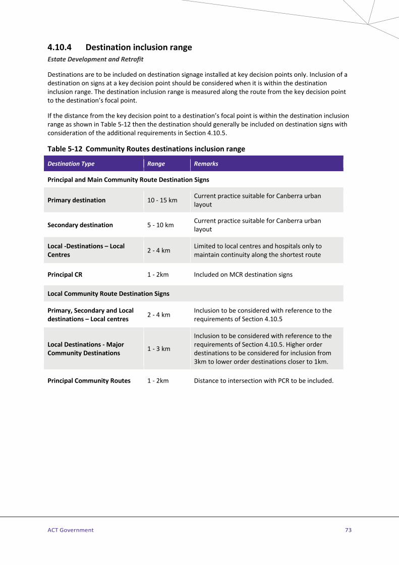
ACT Government 73
4.10.4 Destination inclusion range Estate Development and Retrofit
Destinations are to be included on destination signage installed at key decision points only. Inclusion of a destination on signs at a key decision point should be considered when it is within the destination inclusion range. The destination inclusion range is measured along the route from the key decision point to the destination’s focal point.
If the distance from the key decision point to a destination’s focal point is within the destination inclusion range as shown in Table 5-12 then the destination should generally be included on destination signs with consideration of the additional requirements in Section 4.10.5.
Table 5-12 Community Routes destinations inclusion range
Destination Type Range Remarks
Principal and Main Community Route Destination Signs
Primary destination 10 - 15 km Current practice suitable for Canberra urban layout
Secondary destination 5 - 10 km Current practice suitable for Canberra urban layout
Local -Destinations – Local Centres 2 - 4 km Limited to local centres and hospitals only to
maintain continuity along the shortest route
Principal CR 1 - 2km Included on MCR destination signs
Local Community Route Destination Signs
Primary, Secondary and Local destinations – Local centres 2 - 4 km Inclusion to be considered with reference to the
requirements of Section 4.10.5
Local Destinations - Major Community Destinations 1 - 3 km
Inclusion to be considered with reference to the requirements of Section 4.10.5. Higher order destinations to be considered for inclusion from 3km to lower order destinations closer to 1km.
Principal Community Routes 1 - 2km Distance to intersection with PCR to be included.
ACT Government 74
4.10.5 Destinations to be included on destination signage Estate Development and Retrofit
The following requirements should be utilised to determine the destinations to be included on signage when the destination is within the inclusion range. Note that this will require the web of interconnecting routes that link destinations to be analysed to resolve the destinations to be included at each key decision point.
Continuity – Once a destination has been included on destination signage, the destination is to be shown on destination signage at each key decision point until that destination is reached, to avoid the user becoming lost within the network.
Route to be signed – Where MCRs or LCRs provide for multiple routes to reach the same destination the shortest route from the key decision point only should generally be signed.
Maximum destinations per direction – The maximum number of destinations varies for MCR and LCR destination signs as follows:
> PCR and MCR destination signs - should generally only include a maximum of two destinations per direction. This may be extended to an absolute maximum of four destinations where considered warranted in exceptional circumstances, such as at route commencement from inner urban loops.
> LCR destination signs – the number of destinations signed from a key decision point should be limited to a maximum of four destinations in each direction (2 x 200mm deep fingerboards stacked one on top of the other).
Commencement of inclusion of a destination on signage – In determining the first decision point along a route for signing a destination, the number of destinations which may need to appear on signs at key decision points closer to the destination should be considered. The following points should also be considered:
> To keep the number of destinations on directional signage within the desirable limits, local destinations would not generally be included on destination signs at key decision points on the far side of a town or group centre from the destinations.
> The lower end of the focal distance range may also be used when several destination focal points are near to each other with the higher order destination favoured. In this regard the following destination hierarchy is to be followed on Local Community route signage from higher to lower:
• Local Centres • Hospitals • Links to Primary Community Routes • Colleges; • High schools • District parks • District playing fields
4.10.6 Destination abbreviations Estate Development and Retrofit
The abbreviation of some destinations for focal point names – mainly major community destinations – may be necessary to avoid signs of excessive length resulting in unacceptable wind-loading. The maximum length of fingerboard signs is 1.2m (0.8m preferred) and may restrict destination names to approximately 18 characters (excluding spaces in multi part focal names). Focal point names as they are to appear on signs are available through the ATIPT.

ACT Government 75
4.10.7 Directional signage design Estate Development and Retrofit
General
Layout and design details for all PCR, MCR and LCR directional signs are included below and are detailed on ACTSD-0570-0575. Directional signage types and some brief guidance on use is included in Table 5-13.
MCR and LCR Destination and marker type signs have a white background with AS2700 B23 Bright Blue lettering and symbols. Directional signs use AS1744:2015 Series C typeface. In instances where a more condensed typeface is required to keep sign content length to within maximum limits, AS1744:2015 Series B may be used. PCR route label and reassurance signs are white on bright blue.
CR directional signs utilise the pedestrian and bicycle symbol as a brand for this route type. The symbols face the direction of the arrow, or right when the direction is straight ahead, when included on sign types that include arrows.
Guidance for the design of CR directional signs are shown on ACTSD-0574 with details provided on the following aspects of design:
> Lettering and white space details, edge, letter and line spacings; > Signage layout including arrow placement and list order; > Distance information format and alignment; and > Symbol sizing and arrangements.
For details of the PCR route labels and route brands (CBR Cycle Routes) to be included on CR directional signage refer to ACTSD-0575.
Table 5-13 Community Route directional sign types
Sign No
Type and Example Guidance
GC-01 Main Community Route Marker (also for use on PCRs) To be installed on Principal and Main Community Routes as a route marker at all key decision points in conjunction with MCR destination signs (GC-10 & GC21). Also used for reassurance in Retrofit only. For MCRs – use in conjunction with a GC-04. For PCRs - use with both a GC-09 and GC-04. For full design details refer to ACTSD-0570

ACT Government 76
Sign No
Type and Example Guidance
GC-02 PCR Reassurance sign For use at decision points on PCRs. Note the walker and cyclist are to face in the direction of the arrow or to the right for a straight arrow. S, L, R, LOBL & ROBL GC-02LOBL, GC-02S and GC-02R shown For full design details refer to ACTSD-0570
GC-03 MCR and LCR reassurance sign To be installed at decision points on all Main and Local Community Routes. Note the walker and cyclist are to face in the direction of the arrow or to the right for a straight arrow. S, L, R, LOBL & ROBL GC-03L, GC-03R and GC-03S shown For full design details refer to ACTSD-0570
GC-04 CR Reassurance arrow (Retrofit only) For use in Retrofit only to replace signs on existing routes. Note there are two arrow types, a straight arrow that may be rotated for left and right and an oblique arrow for left and right oblique. S, L, R, LOBL & ROBL GC-04L and GC-04ROBL shown. Design and sign stack details for P/MCRs are on ACTSD-0570
GC-05 PCR Route Label. One route – one direction
Route Label signs are installed on Principal Community Routes at key decision points The alignments of Principal Community Routes and their labels are available through the

ACT Government 77
Sign No
Type and Example Guidance
GC06 PCR Route Label. Single route – two directions
ATIPT. Note that route labels are reversible, and the label is to be shown such that the destination in the label is on the same side of the sign as the destination direction. At route commencement the destination of the route should be shown last in the label. Arrow direction on PCR Route label signs should match those shown on destination signs on the same sign stack. For sign layout details refer to ACTSD-0571 PCRs are branded as CBR Cycle Routes with details of the route brands and labels included on ACTSD-0575.
GC07 PCR Route Label. Two routes – same direction PCR Route Label. Two routes – two directions
GC08 PCR Route Label. Link path
GC-09 PCR Route Brand (Retrofit only)
For use in Retrofit only to be installed to indicate Principal Community Routes. Installed between a GC-01 and GC-04. Further design details are on ACTSD-0571. Route label and route branding details are on ACTSD-0575.
GC-10 MCR Destination sign – Single direction
For installation on PCRs and MCRs at key decision points at intersections between PCRs and / or MCRs only. Sign may include two or more destinations. Single destination signs at PCR / MCR route commencement may include a maximum of generally four destinations. For full design details refer to ACTSD-0570
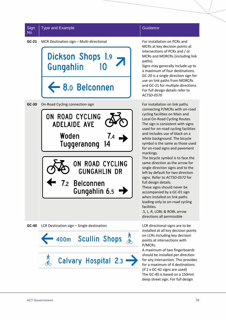
ACT Government 78
Sign No
Type and Example Guidance
GC-21 MCR Destination sign – Multi-directional
For installation on PCRs and MCRs at key decision points at intersections of PCRs and / or MCRs and MORCRs (including link paths). Signs may generally include up to a maximum of four destinations. GC-20 is a single direction sign for use on link paths from MORCRs and GC-21 for multiple directions. For full design details refer to ACTSD-0570
GC-30 On-Road Cycling connection sign
For installation on link paths connecting P/MCRs with on-road cycling facilities on Main and Local On-Road Cycling Routes. The sign is consistent with signs used for on-road cycling facilities and includes use of black on a white background. The bicycle symbol is the same as those used for on-road signs and pavement markings. The bicycle symbol is to face the same direction as the arrow for single direction signs and to the left by default for two direction signs. Refer to ACTSD-0572 for full design details. These signs should never be accompanied by a GC-01 sign when installed on link paths leading only to on-road cycling facilities. .S, L, R, LOBL & ROBL arrow directions all permissible
GC-40 LCR Destination sign – Single destination
LCR directional signs are to be installed at all key decision points on LCRs including key decision points at intersections with P/MCRs. A maximum of two fingerboards should be installed per direction for any intersection. This provides for a maximum of 4 destinations (if 2 x GC-42 signs are used) The GC-40 is based on a 150mm deep street sign. For full design

ACT Government 79
Sign No
Type and Example Guidance
GC-41 LCR Destination sign – Single destination with amenity plates
details refer to ACTSD-0572. No distance is required for destinations within view of the signed destination. GC-41 signs are based on a 200mm deep street sign. For full design details refer to ACTSD-0572 Installation is as for GC-40 signs. Refer to ACTSD-0573 for full listing and details of permissible amenity plates for use. When PCR Route labels are included, the distance should be measured to the intersection with the PCR. PCR route labels and route brands are as shown on ACTSD-0575.
GC-41 LCR Destination sign – Single destinations with PCR link
GC-42 LCR Destination sign – Two destinations
GC-42 signs are based on a 200mm deep street sign. For full design details refer to ACTSD-0572 Installation is as for GC-40 signs,
GC-43 LCR Route commencement sign – Single direction Directional signage on inner urban loops– Single direction
Route commencement signs are to be installed at primary and secondary destinations including town and group centres and local destinations including local centres. For full design details refer to ACTSD-0572 At group and local centres signs are to be installed to be visible from main entrances to shopping centres / areas. For town centres the signs are to be installed at the commencement of P/MCRs from any loop MCR around the town centre rather than close to the focal point.

ACT Government 80
Sign No
Type and Example Guidance
GC-44 LCR Route commencement sign – Multi direction Directional signage on inner urban loops– Two direction
Installation of a GC-44 sign is as for a GC-43 Two GC-43 signs are preferred over a single GC-44 sign when there are more than a total of 6 destinations on a GC-44 sign. Examples of typical sign installations for various destinations are included for: Local centres - ACTSD-0593 and -0594 Group centres - ACTSD-0594 Use of a GC-44 signs on an inner urban loop is as for a GC-45 sign.
GC-45 Directional signage on inner urban loops– Three direction
An LCR type directional sign may be included on P/MCR inner urban loops, generally around Town Centres. In these environments’ facilities are generally located within busy highly urban streetscapes. CR Directional signage should be designed to provide information on a single sign on each approach close to a decision point and be obviously visible and discernible from road signage. Examples of typical sign installations are included on ACTSD-0592
Other signs to assist with wayfinding
Street name signs - Street name signs should be provided in the following circumstances
> at street crossings on P/MCRs if existing signage is not visible from the crossing point. This allows path users to locate themselves on their journey. This requirement may be relaxed if street signs are visible within 50 metres of the crossing. The street sign should be installed parallel with the street crossed, in a location clearly visible and as close as possible to the path crossing.
> on P/MCRs through open space, access paths linking to local streets should be signed with “To “ in front of the street name along the route.
ACT Government 81
4.10.8 Wayfinding on streets with mixed traffic Estate Development
For Principal, Main or Local Community Routes using Active Travel Streets details of directional signage and wayfinding pavement symbols are as for Retrofit.
Retrofit
Directional signs
Where Principal, Main or Local Community Routes use local access streets or minor collectors and a path of the required width is not provided, cyclists may use either the street or the paths (see Sections 4.8.2 and 4.8.5). In these situations, directional signs are to be installed at locations to clearly indicate travel paths and route continuity for both path users and cyclists choosing to use the roadway.
In established areas where MCRs and LCRs use sections of streets without verge paths (see Section 4.8.6) directional signs should be sited to be visible from the street as indicated in ACTSD-0513 and -0514.
For inner urban loops that may include bicycle-only paths directional signs are to be located to minimise clutter in highly-urban streetscapes. The destinations for all directional choices are to be shown on a single GC-43 or GC-44 direction sign on the approach to each decision point.
Wayfinding pavement symbols
Wayfinding is enhanced through installation of pavement symbols that utilise an elongated cyclist symbol with double arrowheads above to indicate the direction of travel on these routes. A walker is included as part of the symbol group on streets without verge paths. These pavement symbols are also installed to raise the awareness of road users to the presence of cyclists that may not usually be comfortable travelling on the roadway and walkers on streets without verge paths.
The pavement symbols also provide guidance on positioning within the roadway for cyclists. The position of the symbol (from the kerb) may vary to respond to the conditions along sections of the street, however symbol positioning should not vary between symbols and be constant between intersections wherever possible. Road centrelines should generally be removed with the installation of wayfinding pavement symbols.
Guidance for the use of wayfinding pavement symbols on roadways to compliment directional signage for Active Travel Streets are shown on ACTSD-0511 and for streets without verge paths refer to ACTSD-0513 and -0514. Pavement markings for use on roadways including layouts and dimensioning are as detailed on ACTSD-3523.
ACT Government 82
4.10.9 Behavioural signage Estate Development and Retrofit
The ‘Share the Path’ Sign (GC-50) has been developed for use on Principal and Main Community Routes to encourage appropriate walking and cycling behaviour by path users. Refer to ACTSD-0580 for sign layout and design details.
The ‘Share the Path’ sign should be used in pairs facing path users approaching from each direction, generally at a spacing of 500m to 1km on Principal and Main Community Routes. Major inflow points onto a Main Community Route, such as paths at a main road junction may require a split installation of the sign to address people moving from the inflow path(s) in either direction on the Main Community Route. Refer to ACTSD-0591 for examples of a split installation. At other locations the signs may be installed on each side of a single pole.
GC-50 signs may also be installed on Local Community Routes and only installed at specific locations to address reported behavioural issues.
4.10.10 Minimum facility requirements to allow route signing Estate Development
Main, Principal and Local Community Route directional signs are only installed when appropriate facilities exist to the destinations to be listed on the signs. Signs are therefore installed on a route by route basis. Ad hoc installation of direction signage is not recommended as isolated signage does not provide for good wayfinding.
Signs may be installed as part of development works which replace or enhance sections of already signed routes. Prior to the installation of directional signs along a route, the route is surveyed and issues addressed regarding any existing facilities, as per the Retrofit requirements outlined below.
Retrofit
Signing a route in Retrofit may bring increased traffic and a perception by users that the route is “safe for use”. The entire route to be signed should be surveyed prior to signing and hazards identified and assessed. Any works required to mitigate hazards are to be completed prior to signing the route. Table 5-14 provides advice on the risk assessment of facilities to identify minimum additional works required to make routes suitable for signing.
The following minimum measures are to be included for directional signage installation projects utilising existing path or street infrastructure:
> Appropriately placed signage in accordance with ACTSD-0592 to warn path users and motorists of crossings ahead
> Removal of all NCDC directional and behavioural signage (yellow letters on brown background) and all other redundant signage
> Installation or repair of cycle rest rails at road crossings where the cyclist does not have priority. Installation is to be at all crossings of minor and major collectors and arterial roads
> Marking with high visibility tape any obstacle within 1m of the path edge including bollards, cycle rest rails and the approach side of fall protection barriers on Main Community Routes
> Linemarking to define priority at Key Decision Points. > Installation of calming treatments on mixed traffic streets to provide an Active Travel Street
environment as detailed in Section 4.8.2 and on ACTSD-0512.

ACT Government 83
Table 5-14 Risk assessment guidance prior to signing of routes
Issue Description Short-term remedial actions Longer-term remedial actions
Path adequacy Is the path adequate to accommodate estimated user traffic? Are good sight lines maintained, and blind driveways and building entrances minimised?
Signing and marking. Repair path imperfections and serious hazards. Sign or mark blind entrances or driveways. If cycling is required on-street, mark the pavement for cycling awareness. Refer to ACTSD-0511 and install measures as detailed in ACTSD-0512 to promote a lower speed environment preferably less than 40km/h
Rebuild path to required width and alignment. Relocate obstructions such as power poles, trees, signage. Install measures to provide an Active Travel Street along the route with a speed environment of 30 km/h
Physical hazards in the roadway or path environment
Are there physical deficiencies or hazards on the roadway or path (drainage grates, large cracks, blind driveways or hidden entrances, bollards and poles on paths etc)?
Sign and mark hazards within 1m of the path edge with reflective tape. Provide contrasting pavement and / or pavement markings on driveway crossings to the requirements of ACTSD-0527 for paths
Complete removal of hazard.
Sight lines and clearances
Are sight lines obscured by obstacles such as signs, trees, fences or parked cars?
Signing and marking to improve sightlines.
Complete removal of hazard.
Intersections, general
Is there adequate operating space in the intersection to accommodate user needs?
Signing and marking. Repair road imperfections and hazards. Refer to ACTSD-0511 and -0592x
Develop paths as a parallel system.
Signalised intersections
Can users comfortably negotiate the intersection? Is there sufficient storage space on any islands for anticipated user volumes?
Signing and marking. Repair road and path imperfections and serious hazards. Investigate installation of priority crossing on slip lanes on Main at crossings (see ACTSD-0520) and Zebra crossings on Local Community Routes (see Section 4.7.3) .
Include user needs in signal phasing and priority crossings for Main and Local Community Routes.
Path crossings of roadways
Is the crossing point adequately marked and signed?
Cycle rest rails at crossings and crossing warning signs on Main and Local Community Routes, install refuge, Path Priority and / or Zebra crossings if warranted. Refer to Sections 4.7.3, 4.7.5 and 4.7.7 for guidance on crossing type selection and details
Installation of Priority and / or refuge crossings or other engineering treatments.
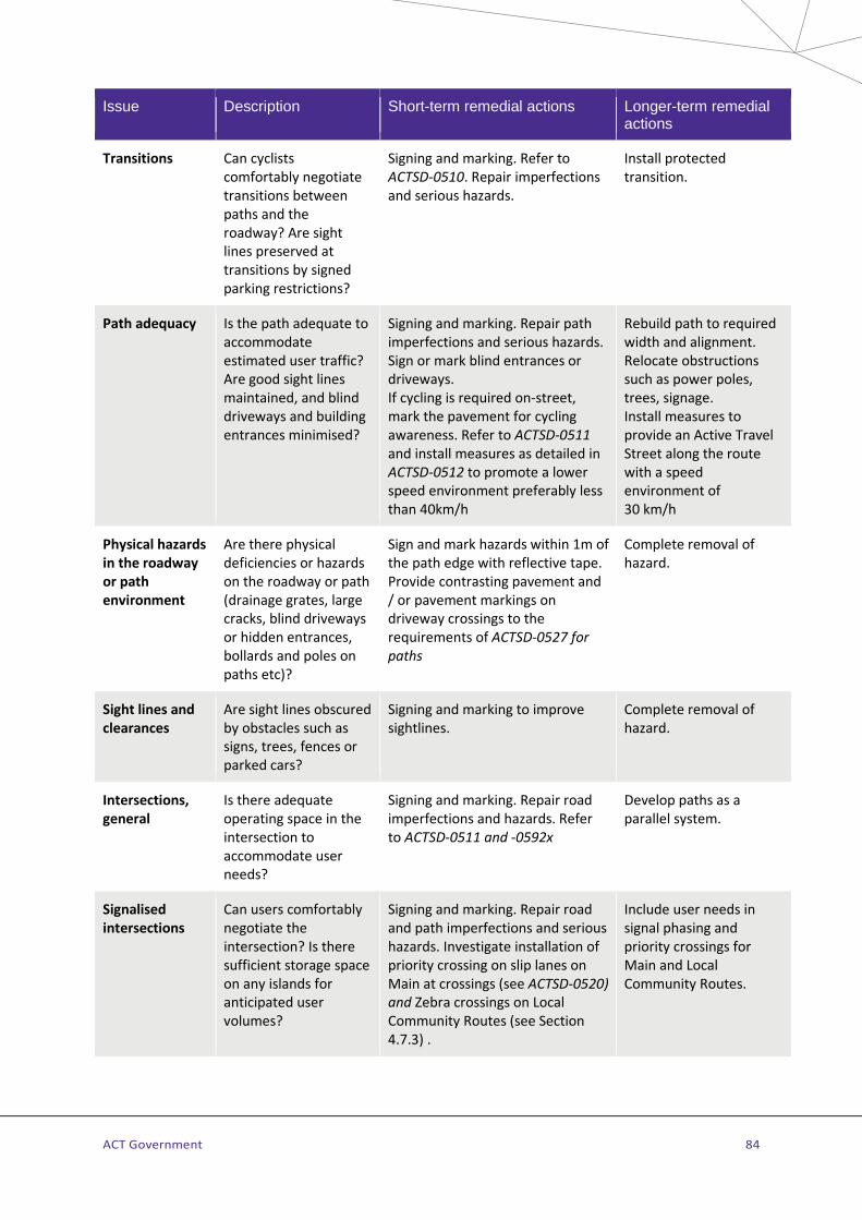
ACT Government 84
Issue Description Short-term remedial actions Longer-term remedial actions
Transitions Can cyclists comfortably negotiate transitions between paths and the roadway? Are sight lines preserved at transitions by signed parking restrictions?
Signing and marking. Refer to ACTSD-0510. Repair imperfections and serious hazards.
Install protected transition.
Path adequacy Is the path adequate to accommodate estimated user traffic? Are good sight lines maintained, and blind driveways and building entrances minimised?
Signing and marking. Repair path imperfections and serious hazards. Sign or mark blind entrances or driveways. If cycling is required on-street, mark the pavement for cycling awareness. Refer to ACTSD-0511 and install measures as detailed in ACTSD-0512 to promote a lower speed environment preferably less than 40km/h
Rebuild path to required width and alignment. Relocate obstructions such as power poles, trees, signage. Install measures to provide an Active Travel Street along the route with a speed environment of 30 km/h
Physical hazards in the roadway or path environment
Are there physical deficiencies or hazards on the roadway or path (drainage grates, large cracks, blind driveways or hidden entrances, bollards and poles on paths etc)?
Sign and mark hazards within 1m of the path edge with reflective tape. Provide contrasting pavement and / or pavement markings on driveway crossings to the requirements of ACTSD-0527 for paths
Complete removal of hazard.
Sight lines and clearances
Are sight lines obscured by obstacles such as signs, trees, fences or parked cars?
Signing and marking to improve sightlines.
Complete removal of hazard.
Intersections, general
Is there adequate operating space in the intersection to accommodate user needs?
Signing and marking. Repair road imperfections and hazards. Refer to ACTSD-0511 and -0592x
Develop paths as a parallel system.
Signalised intersections
Can users comfortably negotiate the intersection? Is there sufficient storage space on any islands for anticipated user volumes?
Signing and marking. Repair road and path imperfections and serious hazards. Investigate installation of priority crossing on slip lanes on Main at crossings (see ACTSD-0520) and Zebra crossings on Local Community Routes (see Section 4.7.3) .
Include user needs in signal phasing and priority crossings for Main and Local Community Routes.

ACT Government 85
Issue Description Short-term remedial actions Longer-term remedial actions
Path crossings of roadways
Is the crossing point adequately marked and signed?
Cycle rest rails at crossings and crossing warning signs on Main and Local Community Routes, install refuge, Path Priority and / or Zebra crossings if warranted. Refer to Sections 4.7.3, 4.7.5 and 4.7.7 for guidance on crossing type selection and details
Installation of Priority and / or refuge crossings or other engineering treatments.
Transitions Can cyclists comfortably negotiate transitions between paths and the roadway? Are sight lines preserved at transitions by signed parking restrictions?
Signing and marking. Refer to ACTSD-0510. Repair imperfections and serious hazards.
Install protected transition.
4.10.11 Directional sign locations and installation General
All signs are to be installed based on site observations and require approval by the Road Authority prior to detailed design and installation.
Signage should be visible and legible for pedestrians and cyclists with particular regard to the eye height and sight lines of users. Signage should be placed as low as possible to permit good visibility by pedestrians and cyclists. Wherever possible, signage should be placed to maximise visibility at night using existing lighting.
Community Route directional signage is to be placed to minimise confusion with road signage. Directional signage for paths is not to be co-located (fixed to the same pole) with road directional signage.
Wherever possible, signs should be installed to minimise the number of new poles, either through use of existing light poles where opportunity allows or use of the back of separated paired signs such as Road Ahead or “Share the path” signs.
Installation layout examples
Examples of signage installation layouts are shown on ACTSD-0590 to -0595. Guidance on directional signs required for various decision points and circumstances are included in Table 5-15.
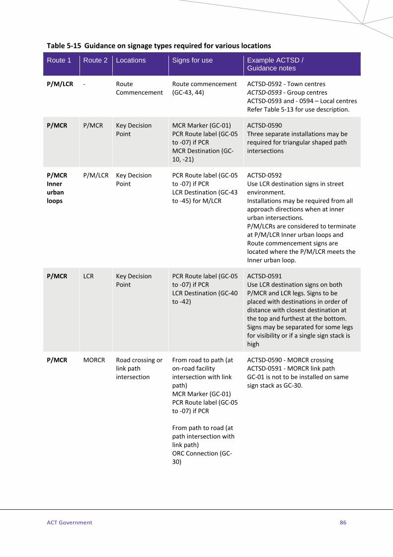
ACT Government 86
Table 5-15 Guidance on signage types required for various locations
Route 1 Route 2 Locations Signs for use Example ACTSD / Guidance notes
P/M/LCR - Route Commencement
Route commencement (GC-43, 44)
ACTSD-0592 - Town centres ACTSD-0593 - Group centres ACTSD-0593 and - 0594 – Local centres Refer Table 5-13 for use description.
P/MCR P/MCR Key Decision Point
MCR Marker (GC-01) PCR Route label (GC-05 to -07) if PCR MCR Destination (GC-10, -21)
ACTSD-0590 Three separate installations may be required for triangular shaped path intersections
P/MCR Inner urban loops
P/M/LCR Key Decision Point
PCR Route label (GC-05 to -07) if PCR LCR Destination (GC-43 to -45) for M/LCR
ACTSD-0592 Use LCR destination signs in street environment. Installations may be required from all approach directions when at inner urban intersections. P/M/LCRs are considered to terminate at P/M/LCR Inner urban loops and Route commencement signs are located where the P/M/LCR meets the Inner urban loop.
P/MCR LCR Key Decision Point
PCR Route label (GC-05 to -07) if PCR LCR Destination (GC-40 to -42)
ACTSD-0591 Use LCR destination signs on both P/MCR and LCR legs. Signs to be placed with destinations in order of distance with closest destination at the top and furthest at the bottom. Signs may be separated for some legs for visibility or if a single sign stack is high
P/MCR MORCR Road crossing or link path intersection
From road to path (at on-road facility intersection with link path) MCR Marker (GC-01) PCR Route label (GC-05 to -07) if PCR From path to road (at path intersection with link path) ORC Connection (GC-30)
ACTSD-0590 - MORCR crossing ACTSD-0591 - MORCR link path GC-01 is not to be installed on same sign stack as GC-30.

ACT Government 87
Route 1 Route 2 Locations Signs for use Example ACTSD / Guidance notes
LCR LCR Key Decision Point
LCR Destination (GC40 to -42)
ACTSD-0593 to -0595 Signs to indicate each leg of the intersection with clear sightlines on each approach.
P/M/LCR Access CR to off-route Focal point
Key Decision Point
LCR Destination (GC40 to -42)
ACTSD-0594 Shortest Access CR is to be signed from each approach direction along the route.
P/M/LCR Access CR
Decision point PCR Reassurance (GC-02) if PCR M/LCR Reassurance (GC-03) if M/LCR Bollard may be used to mount the sign instead of a pole installation (refer ACTSD-0593
ACTSD-0593 and -594 Use at intersections where route direction may be unclear or ambiguous. Required for example where a trunk path forms an intersecting Access CR.
P/MCR or LCR
- Route Reassurance Point
PCR Reassurance (GC-02) if PCR MCR Reassurance (GC-03) if MCR or LCR Bollard may be used to mount the sign instead of a pole installation (refer ACTSD-0593
When P/MCRs or LCRs traverse open space and there are no directional signs for more than 1km install at maximum spacing of 750m – 1km.
P/MCR or LCR
Local Street
Road crossing including underpasses
PCR Reassurance (GC-02) if PCR MCR Reassurance (GC-03) if MCR or LCR G5-1 Street name sign
ACTSD-0591 This requirement may be relaxed if street signs are visible within 50 metres of the crossing.
4.10.12 Directional sign distance measurement Focal point locations for the purpose of the measurement of distances to be included on CR directional signs are available through the ATIPT. The distance included on signs is to be to the nearest 100m as measured from the subject sign location to the focal point location for each destination shown on the sign.
The distance is to be measured is to follow the appropriate P/M/LCR to reach the destination focal point from the subject sign. If the destination focal point is not located on a P/M/LCR then the shortest route using appropriate Access Community Route facilities to reach the destination focal point from the P/M/LCR is to be measured and included as the distance to the destination focal point. For example, an Access Community Route that required the use of stairs to reach the destination would not be appropriate and an alternative route that is accessible by cyclists and pedestrians is to be identified and measured.

ACT Government 88
5 DESIGN OF FACILITIES FOR ACCESSIBLE PEDESTRIAN ROUTES
5.1 General Estate Development and Retrofit
Accessible Pedestrian Routes (see Table 5-1) provide logical and clear walking and wheelchair-accessible routes around prescribed areas to enable people with a vision or mobility impairment to access community facilities in a safe and easy manner. This involves definition of continuous, clear paths of travel (including shorelining provision) with access to all features such as taxi ranks, set down areas, bus stops, building entrances and fixtures.
Main and Local Community Route facilities are not provided where these routes may overlap with an Accessible Pedestrian Route. Ideally where Accessible Pedestrian Routes and Main or Local Community Routes share the same street corridor appropriate facilities should be located in opposite street verges with suitable crossing facilities provided where routes intersect.
Tactile Ground Surface Indicators (TGSIs) are consistently provided on these routes and maintained to the required standards. These routes are also accessible for motorised wheelchairs and people with prams.
The application of TGSI and APR facilities should comply with the advice provided in this section. Refer to the ATRA for the location of APRs.
5.2 Tactile ground surface indicators Estate Development and Retrofit
The purpose of TGSIs is to alert a person with a vision impairment of a hazard, or assist in wayfinding. They are particularly important in public spaces and where pedestrian and vehicle paths cross. They also assist in alerting everyone to potential hazards.
Table 5-16 describes where TGSI are to be installed and provides guidance on the locations.
Table 5-16 Design parameters for Accessible Pedestrian Routes
Location Design requirements
Town and Group centres
A complete network of TGSIs is to be provided on the identified APRs as shown on the ATRA.
Local centres A complete network of TGSIs is provided within local centres as shown on the ATRA or, if not shown, then TGSIs are provided to paths, bus stops and at any path vehicle crossing points on either side of the stop.
Industrial / employment areas
Use of TGSIs is discretionary. In these areas most access is generally by vehicles and pedestrian movement is low.
Suburban land use context
TGSIs are only installed at bus stops or other transport stopping points, paths to bus stops that cross bicycle-only paths and at vehicle crossing points that serve community facilities such as schools, childcare centres, galleries etc,
ACT Government 89
5.3 Indicator types Estate Development and Retrofit
Strict adherence to design requirements is essential to enable consistent interpretation of the two types of TGSIs by people with a vision impairment:
> Warning indicators - a series of raised dots, warning of an impending hazard. or to indicate a change of direction.
> Directional indicators - a series of raised lines providing directional orientation, placed between warning indicators and in a continuous run from the Accessible Pedestrian Routes to the feature to which access is required.
AS1428.4.1 details requirements for the type of TGSIs to be used including sizes, types and finishes.
TGSI manufactured forms TGSIs are manufactured in two forms:
> Discrete TGSIs which are individually installed, and either provide a homogenous luminance for the sloping and upper surface of the truncated cone, or for composite versions, have differing luminance for the sloping and upper surface of the truncated cone. Typically, these TGSI are installed into ground surfaces.
> Integrated TGSIs are in a defined pattern and are of the same luminance and material as the base surface. Typically, they are in mat form, and are recessed or set atop ground surfaces.
Discrete TGSIs are typically located at high amenity, high pedestrian traffic areas such as Group and Town Centres as they provide a ’soft touch’ urban design. However, they require more consideration to ensure the required contrast between the TGSI and the base surface in which they will be installed. They are also used in situations where large tile TGSI (typically integrated TGSIs) are difficult to install due to physical constraints such as complex curves or varying grades.
Integrated TGSIs have a homogenous luminance and material to their base surface, meaning they are often more conspicuous in the urban space. They offer a wide coverage area, generally an easier installation method, and a more cost-effective solution.
Integrated TGSIs are the preferred choice for use on APRs and must be installed into the substrate and not as. ‘blade’ or ‘strip’ installations. Discrete TGSIs should not be used.
TGSIs made from ceramic (non-flexible) material or composite stainless steel are preferred. TGSIs made from other materials (complete stainless-steel products or polyurethane and concrete polymer) should only be used where other materials are not site suitable.
TGSIs should be flush inset into the substrate so as not to create a trip hazard.
ACT Government 90
TGSI locations
Warning indicators are located in accordance with AS1428.4.1 and are required at the following locations on Accessible Pedestrian Routes:
> Road crossings including kerb ramps and at grade island crossings. > Vehicular crossings with poor sight lines. > Overhead obstructions lower than 2m without a kerb or another barrier at least 150mm high. > Sloping faces intruding into the clear path of travel at a point lower than 2m, 300mm out from base
(Note: Such obstacles will meet the 30% luminance criteria). > Top and bottom of stairs and ramps with a gradient of between 1 in 14 and 1 in 20. > Mid-landing of stairs and ramps without continuous handrail. Warning indicators need be 300mm in
depth across the full width of the trafficable surface. > At the end of or at stopping point of directional indicators, or at change of direction of directional
indicators. > At bus stops in accordance with ACTSD-0530 to -0532.
Directional indicators are required on Accessible Pedestrian Routes as follows:
> Midblock crossings. > At T intersections. > To bus timetables. > At bus stops in accordance with ACTSD-0530 to -0532. > To major signage (beacons).
Across large open spaces where no other route or tactile cueing is available, installation of directional indicators may be beneficial (eg to a point of entry to a significant public facility).
5.4 Design of TGSI at crossing points Estate Development and Retrofit
Warning TGSIs should be installed at crossing points to meet the following requirements:
> at least 1,000mm wide and cross the path of travel (or access way); > perpendicular to the path of travel; > set back at 300mm +/- 10mm from the edge of the hazard (a vehicle crossing or road is a hazard); and, > a depth of 600mm to 800mm.
Where a change of direction indication is required, or where connection to directional TGSI is required:
> on a kerb ramp which is part of the access way, and > at bus and light rail stops, as shown in ACTSD-0530-33
Directional TGSIs should be installed:
> to guide users from one point to another (usually bounded by warning TGSI); and, > at mid-block or similar crossings to indicate the position of the crossing.
Directional TGSIs should be installed to meet the following requirements:
> 600mm wide at the main access-way location, or > 300mm wide if between warning TGSI.
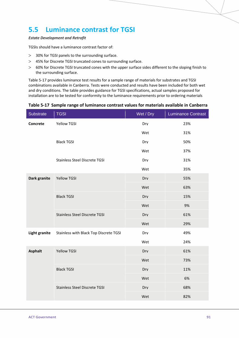
ACT Government 91
5.5 Luminance contrast for TGSI Estate Development and Retrofit
TGSIs should have a luminance contrast factor of:
> 30% for TGSI panels to the surrounding surface. > 45% for Discrete TGSI truncated cones to surrounding surface. > 60% for Discrete TGSI truncated cones with the upper surface sides different to the sloping finish to
the surrounding surface.
Table 5-17 provides luminance test results for a sample range of materials for substrates and TGSI combinations available in Canberra. Tests were conducted and results have been included for both wet and dry conditions. The table provides guidance for TGSI specifications, actual samples proposed for installation are to be tested for conformity to the luminance requirements prior to ordering materials
Table 5-17 Sample range of luminance contrast values for materials available in Canberra
Substrate TGSI Wet / Dry Luminance Contrast
Concrete Yellow TGSI Dry 23%
Wet 31%
Black TGSI Dry 50%
Wet 37%
Stainless Steel Discrete TGSI Dry 31%
Wet 35%
Dark granite Yellow TGSI Dry 55%
Wet 63%
Black TGSI Dry 15%
Wet 9%
Stainless Steel Discrete TGSI Dry 61%
Wet 29%
Light granite Stainless with Black Top Discrete TGSI Dry 49%
Wet 24%
Asphalt Yellow TGSI Dry 61%
Wet 73%
Black TGSI Dry 11%
Wet 6%
Stainless Steel Discrete TGSI Dry 68%
Wet 82%
ACT Government 92
6 DESIGN OF FACILITIES FOR EQUESTRIAN ROUTES 6.1 General Estate Development and Retrofit
Equestrian Routes (ERs) are a series of defined routes for horse riders in suburban and rural land use contexts within the ACT. ERs are generally located on the periphery of residential areas, along river corridors and through inter-town buffer spaces (see Table 5-1). Routes are kept away from schools, sportsgrounds, shops and playgrounds. Equestrian Routes are often located in open space corridors adjacent to principal recreational trails and walker-only trails.
Refer to the ATRA for the location of ERs.
6.2 Facilities for Equestrians Four classes of facility are used in the Equestrian Route component of the ATR:
> Equestrian Trails (see ACTSD-0601) > Cavalettis, horse gates, underpasses, bridges and floodway crossings (see ACTSD-0602, -0610, -0611
and -0615) > Road and path crossings (see ACTSD-0605, and ACTSD-0606 for signalised crossings) > Horse paddocks and agistment areas including activity centres
6.2.1 Equestrian trails Estate Development and Retrofit
There are three types of equestrian trails: urban, rural and interstate. An example of an interstate trail is the National Bicentennial National Trail which passes through the ACT. All trails are signed with priority accorded to urban trails with trail signposting installed across the ACT trail network.
Equestrian trails are usually developed with a minimum of road crossings to allow riders to cover longer distances with fewer interactions with traffic. Equestrian trails are usually provided for a horse-and-rider. Where special trails are provided to include harness horses these trails should be compatible with the management intentions of the areas adjacent to the trail and allow for wheeled vehicles, including harness rigs. This type of trail is not possible in many areas as the 3.0m wide gates required by harness horses would permit unauthorised trail access by motor vehicles and trail bikes.
Trail width
Normal use – grassed surface - minimum width: 5.0m. desirable width: 10m. High use - granular surface – minimum width: 3.0m
Requirements (see also ACTSD-0601):
> 5m wide trails should not be bordered by barbed wire fencing or similarly hazardous obstacles. Trails located adjacent to existing barbed wire stock fencing, should be sited with 5.0m clearance to the stock fence.
> In high usage situations or where the existing or proposed trail alignment is subject to infrequent inundation and erosion, a stabilised surface trail of 3.0m minimum width will be provided as per ACTSD-0601.
> Where an ER parallels a Community Route, facilities are to be separated by a verge of at least 3.0m.

ACT Government 93
Overhead clearance:
Clearance along equestrian routes from overhanging branches and similar obstructions should be 5.0m. See Section 6.2.3 for underpass clearances.
Trail surface
Equestrian trails do not require a solid paved surface such as concrete or asphalt. Where trail erosion is most likely to occur, a packed (small diameter) gravel base with side drainage should be provided.
Surfacing considerations (see ACTSD-0601 for details on high-use trails):
> On longitudinal gradients of more than 1:4 or cross slopes of more than 1:6, the surface must be free draining and firm. Muddy or gravely surfaces at slopes greater than those quoted are more likely to cause horse and rider to fall, particularly in wet weather. Non-slip surface treatments must be applied where the risk of slippage is real. The US Federal Highway Administration on-line design manual Equestrian Design Guidebook for Trails, Trailheads, and Campgrounds provides guidance on surface treatments. Search for manual at http://www.fhwa.dot.gov.
> Where usage is heavy, consideration may need to be given to stabilising the surface against erosion. See equestrian trail granular surfacing material specification on ACTSD-0601.
> Low level crossings of watercourses are acceptable on equestrian routes, provided the bottom of the crossing is firm, and ramps leading to the crossing do not exceed slopes of 1:4.
> Warning signs and depth indicators should be provided on signed equestrian routes.
Bridges and provision at structures
Bridges used by equestrians should be a minimum of 2.0m wide, particularly on the Bicentennial National Trail for packhorse traffic. Bridge decking should provide an even surface free of gaps or mesh which may catch and present a hazard to horseshoes.
Safety wings should be provided to guide users onto and off the bridge. Bridge railings may be timber or steel and are mounted at a minimum height of 1.5m to present a smooth continuous surface free of protrusions or bracketing which may snag a passing horse or rider. Fixing bolt heads should be countersunk or recessed into the railing material.
Horse Gates
Gates with an opening width of 1.5m to regulate access to and from equestrian trails should be designed to swing freely and without obstruction in both directions. Signage should not impede the horse-rider’s approach to, nor opening of, the gate.
Spring-loaded horse gates are not preferred. They are difficult to manage and can cause injury to horses and riders. Farm gates that swing both ways are preferred. Horse gates have a tendency to drop over time and they are rarely maintained. Drop latches are preferred on gates as they are easier to manage from a horse.
Gates are hung as high as possible, so they are not so easily impeded by vegetation growth. These gates can be easily managed from horse back with one hand. Gates should be sited on level ground, not on sloping ground. Horse gates are not used on the Bicentennial National Trail as pack horses cannot negotiate them.
Cavalettis
Cavalettis, or step-through gates, are used in the Canberra region as horse gates where other measures cannot exclude motor bikes. Design and construction guidance for cavalettis is provided in ACTSD-0602.
ACT Government 94
6.2.2 Path crossings Estate Development and Retrofit
Where ERs cross Main and Local Community Routes warning signage is provided as detailed on ACTSD-0605). The siting and layout of Equestrian / Community Route crossings should provide adequate sight distances and clearances applicable to a normal Community Route junction – See Section 4.7.1.
6.2.3 Road crossings Estate Development and Retrofit
Equestrian trail crossings of arterial roads and rural roads are provided either by means of underpasses – see ACTSD-0610 and -o611, or at-grade signalised equestrian-compliant crossings (Pegasus Crossing) – see ACTSD-0606, or uncontrolled crossings – see ACTSD-0605. At most sites it will be possible to include provision for equestrians in any existing or new signalised crossing or uncontrolled crossing.
On other road types, careful siting, warning signage and, if necessary, parking restrictions and reduced speed limits are used to provide clear indication and warning of the crossing point (ACTSD-0605). Refuge islands are not used for ER uncontrolled street crossings.
Additional design guidance on equestrian compliant crossings can be found in US Federal Highway Administration on-line design manual, Equestrian Design Guidebook for Trails, Trailheads, and Campgrounds. Search for this title at http://www.fhwa.dot.gov.
Underpasses
Estate development
Where Community and Equestrian Routes run parallel or coincide, arterial road underpasses are designed to provide separate travel paths for equestrians and walkers/cyclists. Details for Community Route underpasses are provided in 0. Underpasses designed for equestrians have a clearance height of 3.7m. See ACTSD-0610 for an example of a separated underpass that includes a road and Community and Equestrian Routes. ACTSD-0610 includes an example of an underpass with separated Community and Equestrian Route facilities. Both drawings provide details of signage and marking details.
Retrofit
For existing situations where the underpass infrastructure does not allow for separation, the ER and CR may share the same underpass and path requires signage to become a designated multi-use path – see ACTSD-0611 for signage and marking details. The clearance height of retrofitted underpasses is 3.7m (3.0m minimum).
The design of underpass approaches should provide adequate sightlines and speed mitigation, especially on sloping approaches. Entries to underpasses should be made as natural as possible, without grids, gates or other unnatural obstacles to will spook horses. Concrete spoon drains are preferable to grids.
Where equestrians are required to dismount on underpass approaches due to inadequate clearance heights or widths, mounting blocks shall be provided on each approach. The design of these is to be in accordance with designs shown in Chapter 7 of Equestrian Design Guidebook for Trails, Trailheads, and Campgrounds. Search for this title at http://www.fhwa.dot.gov

ACT Government 95
Signalised crossings
Estate Development and Retrofit
A Pegasus Crossing is a signalised equestrian crossing, similar in layout to a marked foot crossing with the following differences:
> Signal activation buttons are mounted 2.0m above the ground and at set back from the road to permit horse and rider to safely store clear of any intersecting roadway or parallel paths.
> Signal phase timing is set to provide a crossing time suitable for walking horses. > Equestrian-only crossings parallel to a separate Community Route crossing will have AS1742
equestrian symbols on their crossing lanterns. > Combined crossings will have a crosswalk width of 5m and additional “Equestrians Permitted” plates
fitted to the tops of the signalised crossing lanterns.
See ACTSD-0606 for design details on at-grade signalised Equestrian Crossings.
Uncontrolled crossings
Estate Development and Retrofit
Usually Equestrian Routes are developed apart from the road network with grade-separation the preferred crossing method. In existing situations where ERs cross access streets and low-volume rural roads, an uncontrolled crossing similar in concept to a Community Route uncontrolled crossing (see Section 4.7.11) can be provided as a separate facility or parallel to a Community Route crossing. Where parallel crossings are provided, these should be spaced 3m apart.
Uncontrolled street crossings should conform with the design and construction requirements of Community Route crossings as detailed in Section 4.7.11. Additional detail and signage requirements are provided in ACTSD-0605.
Refuge islands should not be used in conjunction with uncontrolled equestrian crossings.
6.2.4 Floodway crossings Floodway crossings are used to provide a firm and durable surface where ERs cross minor streams and floodways. Guidance on the design and construction of floodway crossings for use on ERs is provided in ACTSD-0615.
6.2.5 Directional signage for Equestrian Routes Estate Development and Retrofit
Equestrian Routes are provided with wayfinding signage on identified Equestrian Trails. Behavioural signage is also fitted in locations where Principal Recreation Trails may overlap or cross an Equestrian Trail on an Equestrian Route.
Wayfinding and warning signage for ERs is detailed in Standard Sign Drawings listed on the ATIPT.
6.2.6 Activity and agistment areas Estate Development and Retrofit
Activity areas are in the range 3-5 hectares on reasonably level ground with good drainage. These areas are managed as public facilities and allocations for use are made in a manner similar to that for playing fields. Pony clubs using an activity area as a home ground are treated similarly to football or other field sport codes.

ACT Government 96
Activity areas are provided near to and accessible from at least two agistment areas (preferably by a direct route). Agistment areas should be no further from residences than 5km, but should not directly abut residential leases. It is desirable to have competition areas slightly removed from agistment areas, to minimize the tendency of competing horses wanting to rejoin others in adjacent paddocks.
Where there is no activity area within 2km of an agistment area, a small area of no more than 2ha should be located on level ground for daily practice and training.
Agistment areas need to be at least 40ha in area, and maximum use is normally made of existing fencing. Facilities typically comprise a feeding area and car park, a practice activity area, several paddocks, entry roadway for vehicles and a safe entry/exit for horses. Agistment area car parks should be large enough to cater for the number of agistees who keep horses at the facility with enough additional space to turn a 4x4 or truck towing a horse float.
Agistment areas should be large enough to allow rotation of paddocks for management purposes, and are stocked at the rule-of-thumb stocking rate of one horse per hectare. Agistment yards must be provided with shade. Gates in stock paddocks should be latched on the outside of the paddock.
Feeding areas are provided to serve the agistment paddocks; the feeding area is less than 0.4ha with adequate gates and barriers to allow access for horses from each paddock. Hitching rails one metre in height should be provided in the feeding area.

ACT Government 97
7 DESIGN OF FACILITIES FOR ON-ROAD CYCLING ROUTES
Table 5-18 Scope of Section 7 – Facilities for use on On-Road Cycling Routes
Type of facility and variation Coverage in Austroads guides
Coverage in these guidelines
On-road lanes
Bicycle lanes AGRD03 Section 4.8.7 Section 0
Marked shoulders and bicycle markings in Retrofit AGRD03 Section 4.8.9 Section 0
Termination of bicycle lanes and marked shoulders AGRD03 Section 4.8 Section 7.1.3
Cycling lanes adjacent to bus lanes AGRD03 Section 4.9 Section 7.1.4
Coloured surface treatments AGRD03 Section 4.8.7 Section 7.3
Bicycle facilities at intersections
With signals AGRD04A Section 10.6 and Appendices Section 7.2.2
Without signals AGRD04 Section A.17 and Commentary 1.4 Section 7.2.4
On-road lanes at path crossings - Section 7.2.3
Roundabouts AGRD04B Section 5.3 Section 7.2.5
Retrofitting intersection cycle facilities Section 7.2
Transitions
Path to on-road facilities & on-road facilities to path AGRD03 Figure 4.36 Section 7.2.5
Directional signage AGTM10 Appendix C Section 7.4
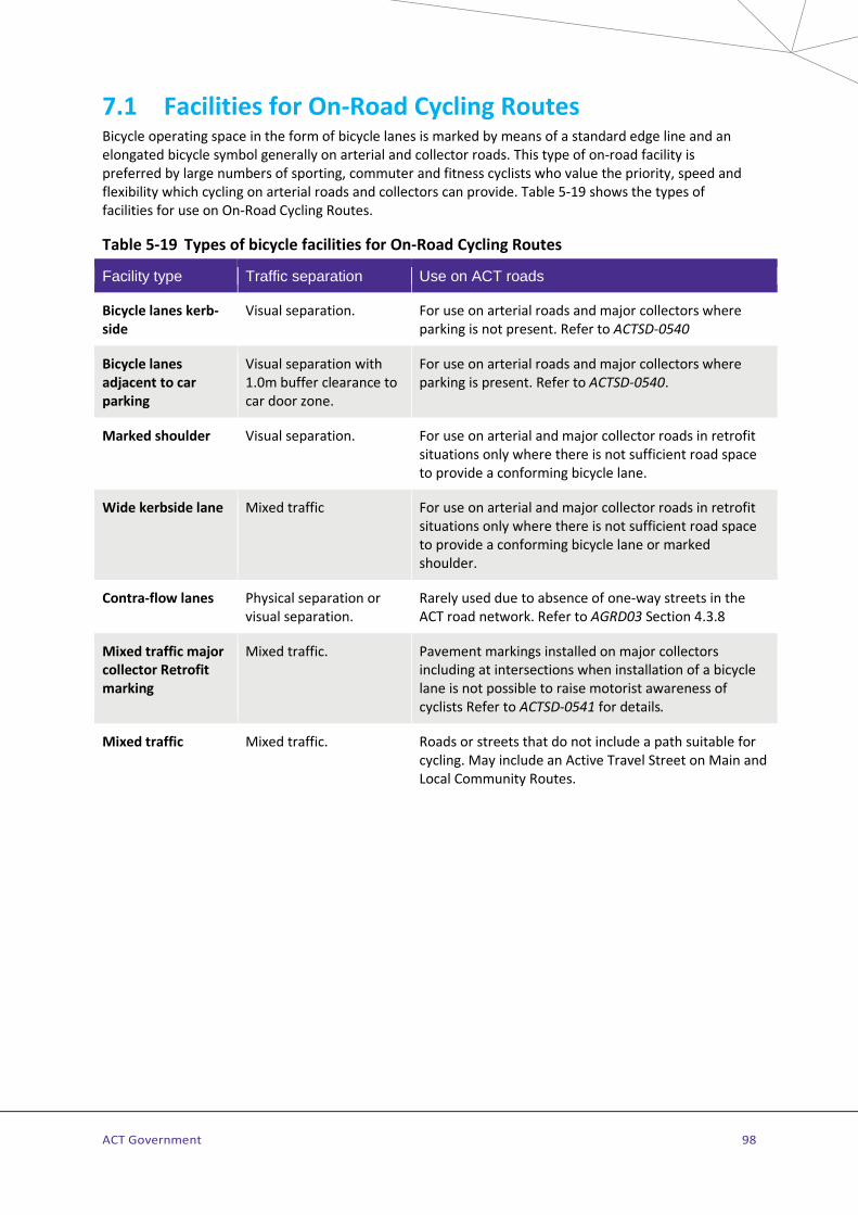
ACT Government 98
7.1 Facilities for On-Road Cycling Routes Bicycle operating space in the form of bicycle lanes is marked by means of a standard edge line and an elongated bicycle symbol generally on arterial and collector roads. This type of on-road facility is preferred by large numbers of sporting, commuter and fitness cyclists who value the priority, speed and flexibility which cycling on arterial roads and collectors can provide. Table 5-19 shows the types of facilities for use on On-Road Cycling Routes.
Table 5-19 Types of bicycle facilities for On-Road Cycling Routes
Facility type Traffic separation Use on ACT roads
Bicycle lanes kerb-side
Visual separation. For use on arterial roads and major collectors where parking is not present. Refer to ACTSD-0540
Bicycle lanes adjacent to car parking
Visual separation with 1.0m buffer clearance to car door zone.
For use on arterial roads and major collectors where parking is present. Refer to ACTSD-0540.
Marked shoulder Visual separation. For use on arterial and major collector roads in retrofit situations only where there is not sufficient road space to provide a conforming bicycle lane.
Wide kerbside lane Mixed traffic For use on arterial and major collector roads in retrofit situations only where there is not sufficient road space to provide a conforming bicycle lane or marked shoulder.
Contra-flow lanes Physical separation or visual separation.
Rarely used due to absence of one-way streets in the ACT road network. Refer to AGRD03 Section 4.3.8
Mixed traffic major collector Retrofit marking
Mixed traffic. Pavement markings installed on major collectors including at intersections when installation of a bicycle lane is not possible to raise motorist awareness of cyclists Refer to ACTSD-0541 for details.
Mixed traffic Mixed traffic. Roads or streets that do not include a path suitable for cycling. May include an Active Travel Street on Main and Local Community Routes.

ACT Government 99
7.1.1 Bicycle lanes Estate Development and Retrofit
Bicycle lanes provide a visually separated operating space for cyclists on arterial roads and major collectors where the prevailing road speed and traffic volume requires a degree of separation. Cyclists are required to use these lanes unless it is impracticable to do so (Australian Road Rule 247).
Bicycle lanes are part of the roadway and are defined by means of an edge line separating bicycle traffic from either moving traffic or parked vehicles. For kerb-side lanes, a standard edge line is used. On streets where motor vehicle parking is permitted, an additional broken parking bay continuity line is placed on the left-hand edge of the bicycle lane.
Bicycle pavement symbols to regulate the facility are placed following side road intersections and at 75m intervals. The pavement marking combination of an elongated bicycle symbol above the lettering “LANE” is used to mark the start of a bicycle lane when not associated with an intersection. When a bicycle lane terminates mid-block, the point of termination is marked with pavement marking combination consisting of an elongated bicycle symbol above the lettering “LANE ENDS” with the word “ENDS” to the bottom of this group. Details of the symbol and lettering are included on ACTSD-3523.
Green coloured pavement may be used in special circumstances to increase lane visibility in conflict zones such as across left turn slip lanes and high turnover parking bays. Refer to Section 7.3 for permitted uses of green pavement.
Different types of bicycle lane layouts and linemarking are detailed in ACTSD-0540. Additional technical advice on lane widths in Estate Development is provided in AGRD03 Section 4.8 and for retrofitted lanes on arterial roads and major collectors, see Table 5-20 and Retrofit only section below.
Where space permits, bicycle lanes should be wide enough for one cyclist to pass another without deviating significantly from the lane (1.5m min). If both bicycle lane and adjacent travel lanes are very wide this may also increase motor vehicle speeds.
Figure 5-10 Bicycle lanes (above left – kerbside lane, above right – car-side lane) Location: Canberra City, ACT. Use of green pavement colour is warranted due to adjacent high turnover car parking.

ACT Government 100
a) Bicycle lanes against the kerb (no car parking)
Where bicycle lanes are located on a roadway without parking, the pavement condition should be free of potential hazards such as drainage grates and cracked or uneven interface between road surface and gutter. Minimum widths for bicycle lanes are measured from the joint between the road surface and concrete gutter and if no gutter is present, to the face of the kerb.
b) Bicycle lanes adjacent to car parking
Cyclists must be able to keep a safe distance from opening parked car doors without deviating from the lane. Refer to ACTSD-0540 for details and layout.
c) Bicycle contra-flow lanes – kerb-side or car-side
Bicycle contra-flow lanes are part of the road usually the kerb lane and sometimes to the right of marked parking. This type of bicycle lane is rarely used in the ACT due to absence of one-way streets in the road network.
A contra-flow lane is separated from oncoming traffic and or parked vehicles by means of continuous white lines (visual separation) or a raised median (physical separation) - see AGRD03 Section 4.3.8 and NSWBG Section 5.1.4 for further advice. Green coloured pavement, bicycle pavement symbols and pavement travel direction arrows are required when contra-flow lanes use visual separation only. Green coloured pavement is required within all contra-flow bicycle lanes where these cross side streets and high-use driveways (>100vpd) to maximise their visibility. At intersections cyclists using a contra-flow lane should be brought out into clear view of motorists and not hidden behind parking or other obstacles.
Night time visibility of the bicycle contra-flow lane by motorists (especially in wet weather conditions) can be enhanced by placing raised pavement markers just inside the adjacent vehicle lane facing oncoming traffic to indicate the contra-flow lane line.
Figure 5-11 Bicycle lane retrofitted to an arterial road Bicycle lane on Adelaide Avenue divided carriageway at Curtin, ACT complemented by an adjacent trunk path serving both
cyclists and pedestrians.

ACT Government 101
Retrofit only
When adjusting road space on arterial roads and major collectors to include retrofitted on-road cycling facilities, consideration is given to the choice of cycle and traffic lane widths to be used. Table 5-20 provides guidance for suitable lane widths for both motorists and cyclists.
Bicycle lanes should be provided wherever possible, considering the following measures:
> Reduction in speed limit to allow the provision of a conforming bicycle lane and traffic lanes of acceptable lane widths within the available road width.
> Provision of marked shoulders where the existing road width will not allow provision of a bicycle lane and excessive cost prevents pavement widening (refer Section 7.1.3).
> Suitability of parking arrangements along the route. For marking bicycle lanes adjacent to parking, refer to AGRD03 Section 4.3.7. Also consider use of green treatment where warranted (refer to Section 7.3).
> Intersection treatments including advanced stop boxes and detector loops at signalised intersections (refer to Section 7.2.1).
> Removal of redundant pavement markings and raised road pavement markers (RRPMs) refer to Section 7.1.7.
> Adequacy of existing lighting. Lighting improvements may be necessary both mid-block and at intersections.
Table 5-20 Bicycle lane widths on arterial roads and collectors in Retrofit
Speed Environment
Bicycle lane width Traffic lane widths
50-60 km/h desirable 1.5m minimum 1.2m (marked shoulder minimum width 1.0m refer Section 7.1.2)
Left hand traffic lane where volume of heavy vehicles/buses is high - desirable 3.5m
- minimum 3.3m Other lanes - desirable 3.3m - minimum 3.0m Left turn lanes - low traffic volume (< 3,000 turning vpd), bicycle lane may be incorporated into turn lane - high traffic volume (> 3,000 turning vpd), minimum width 3.0m
≥ 80km/h desirable 2.0m minimum 1.8m (marked shoulder minimum width 1.0m refer Section 7.1.2)
Left hand traffic lane where volume of heavy vehicles/buses is high - desirable 3.5m
- minimum 3.3m Other lanes - desirable 3.5m
- minimum 3.3m (3.2m for 8.3m carriageway width) Left turn lanes: - low traffic volume (< 3,000 turning vpd), bicycle lane may be incorporated into turn lane; - high traffic volume (> 3,000 turning vpd), minimum width 3.0m
ACT Government 102
Before applying minimum widths shown in Table 5-20, assess the adverse impacts of traffic lane-width reduction including:
> road geometry - sight lines through any curves; > speed environment; > surface roughness; > vehicle mix including heavy vehicle and bus usage; and, > for right hand side lanes:
• gutter width and drainage sump inlet intrusions; and, • sight distance
The following rules also apply when using Table 5-20:
> Minimum bicycle lane widths are used as a last resort. Reduce traffic lanes to minimum widths before considering reducing bicycle lane widths.
> For roads with a speed environment of 60km/h, traffic lane widths should be reduced to a minimum prior to reducing bicycle lane width below 1.5m.
> Where the bicycle lane will be less than 1.5m wide, the following should occur: • After reduction of traffic lanes to minimum widths and available pavement space allocated to
the bicycle lane, design drawings are to show fixed traffic lane widths from the right hand kerb and describe the rationale for the widths used on the drawings.
• Pavement smoothness in the bicycle lane is to be to a high standard, and the full width of bicycle lane pavement should be made useable.
• To minimise the risk of unacceptable pavement lipping at the gutter tray interface, practitioners should consider overlay of the gutter tray with appropriate treatments at storm water sumps.
• Narrower bicycle lanes than those shown may be considered for short distances (maximum 50m) with appropriate signage eg: where the cost of providing the minimum bicycle lane width is prohibitive (eg. narrow bridges or other "squeeze points") and the loss of amenity may be balanced by the provision of a continuous facility. Refer to Queensland TMR Technical Note TN137 Bicycle Activated Warning Signs for information on hazard marking of “squeeze points” such as narrow bridges.
• Minimum traffic lane widths may be reduced to an absolute minimum of 3.2m where kerb widening may be avoided and road geometry and surface roughness are considered acceptable.
• For right hand lanes, when the use of minimum traffic lane width is proposed, careful consideration should be given to gutter width, road geometry, sight distance, drainage sump inlet intrusions and surface roughness. Make improvements where necessary before reducing the lane to minimum width.
For further guidance on traffic lane widths also refer to AGRD03 Section 4.8 and AGTM05 Section 3.

ACT Government 103
7.1.2 Marked shoulders Retrofit only
In Retrofit situations, where the minimum path width standards cannot be achieved and road widening is not feasible, the provision of a marked shoulder may be considered. A marked shoulder may only be installed if it is minimum width of 1.0m, including any gutter tray.
On Main On-Road Cycling Routes, a marked shoulder is preferred to a widened kerb-side lane on arterial roads. This defines the continuity of the route as an interim measure until road widening can be completed in the long term.
Where a bicycle lane leads into a marked shoulder, the pavement marking group consisting of a "bicycle (symbol) above the letters “LANE” above the letters END" is to be applied at the commencement of the marked shoulder.
To allow loose sealing aggregate (stone) to be removed by traffic action prior to marking, the marked shoulder may be installed several months after resealing has occurred.
7.1.3 Termination of bicycle lanes and marked shoulders Estate Development and Retrofit
Wherever a bicycle lane or marked shoulder ends, the edge line defining the facility should not run into the kerb or pavement edge. Instead the bicycle lane or marked shoulder should be terminated at full lane width. If this is not possible, a minimum width of 1.0m for a marked shoulder, or 1.2m (60km/h) to 1.5m (70km/h and above) for a bicycle lane will allow cyclists to merge into the adjacent traffic lane, Refer to ACTSD-0540 for details. A zip merge treatment similar to AS1742.2 Figure 4.16 is to be used for lane terminations in preference to a lane-change type merge.
This provision applies on approaches to intersections as well as to mid-block terminations. Details of the termination treatment and its use in combination with a road to path and path to road transition are provided in ACTSD-0510.
The terminating bicycle lane is marked with the pavement marking combination of an elongated bicycle symbol above the lettering “LANE END” with the word “END” to the bottom of the group. Refer to ACTSD-3523 for pavement marking details
7.1.4 Bicycle lanes adjacent to bus lanes Estate Development and Retrofit
In the ACT cyclists may not legally use bus lanes. Where bus lanes are provided, bicycle lanes should be provided on the kerbside edge of the roadway. On Main On-Road Cycling Routes where bicycle lanes or marked shoulders are provided adjacent to bus lanes, the continuity of bicycle lanes should be preserved through intersections. This is particularly important at high-speed exits, slip lanes and at bus stops. Additional guidance is provided in AGRD03 Table 4.22, NSWBG and the Austroads research report APR266/05 Bus-Bike Interaction within the Road Network.

ACT Government 104
7.1.5 Pavement marking of Main On-Road Cycling Routes Retrofit only
Main On-Road Cycling Routes on major collectors use pavement markings in accordance with ACTSD-0541 for continuity and to promote driver awareness of cyclists in Retrofit where it may not be practicable to provide visual separation through a bicycle lane or marked shoulder as part of scheduled maintenance works.
Details of the cycle symbol and double arrow are included on ACTSD-3523. Note that the double arrow on these routes always points straight as it is not intended as a wayfinding device as is the case on Main and Local Community Routes. Also the cycle symbol is used instead of the rider symbol to reinforce it is not a marking a MORCR rather than a facility forms part of a Main or Local Community Route.
7.1.6 Raised retroreflective pavement markers Estate Development and Retrofit
Raised Retroreflective Pavement Markers (RRPMs) may be used to assist in the delineation of bicycle lanes and to deter motorists from cutting into a bicycle lane on bends or other locations. Use of red RRPMs spaced 2.0m to 5.0m apart and placed on the outside of a B1 barrier line is recommended. This type of treatment may only be installed with the approval of the Road Authority.
RRPMs are not placed within the bicycle lane as they can cause a danger to cyclists. RRPMs should not be placed within pedestrian movement corridors where they are a hazard to walkers.
7.1.7 Removal of redundant linemarking and RRPMs Retrofit only
When linemarking of road pavement is altered, the removal of any existing raised pavement markers or linemarking is to be executed to minimise any risk of confusion to road users. Following the removal of such devices, the pavement is to be left smooth and with a surface texture similar to the surrounding pavement.
Following road upgrades and regular maintenance, RRPMs wrongly located within a bicycle lane or marked shoulder area should be removed as they can present a hazard to cyclists.
7.1.8 Provision for cycling on-street at traffic calming devices Estate Development and Retrofit
Local area traffic management treatments such as chicanes, raised platforms and mini roundabouts should be designed so that cyclists on the road are not forced or squeezed into unsafe situations. This may be achieved by providing a separate bypass route for cyclists (with its own feeder/exit lane) or by allowing sufficient road width for a car and cyclist to pass without hazard. Examples of suitable treatments are provided in AGTM08 and recommended minimum kerbside lane widths are indicated in AGRD03 Sections 4.2.4, 4.8.11 and Commentary 7.

ACT Government 105
7.2 Facilities for On-Road Cycling Routes at intersections
7.2.1 General Estate Development and Retrofit
This section provides detailed recommendations and treatment examples for providing On-Road Cycling Route bicycle facilities through intersections. AGRD04, AGRD04A, AGRD04B and ACTSD-0540 and 3540 provide detailed advice on intersection treatments. Bicycle lanes are to be continuous including across side street intersections. Lane markings are not marked across signalised intersections. Refer to MIS 13 Traffic Control Devices and ACTSD-3540 for details of line marking at signalised intersections.
Figure 5-12 details a design framework for providing visually separated operating space for cyclists at intersections, and summarises the six intersection elements: mid-block, transition, approach, waiting, through, and departure.
Figure 5-12 The six design elements of a signalised intersection Source: NSWBG
The primary aim of the road designer is to provide cyclists with a clear and unambiguous travel path through an intersection. Bicycle facilities should be continuous through the intersection. If bicycle lanes are provided on approach, these should be resumed on the departure side of the intersection. On approach, the cyclist first enters the most difficult part of the intersection as they may have to make a transition across lanes (to a right-turn lane) or have their lane crossed by other vehicles. Once in their chosen lane, they proceed to the intersection holding line to await the signal to proceed.
Though Figure 5-12 depicts an intersection controlled by traffic signals, the six design elements can apply to any type of intersection and should be considered in the design of unsignalised intersections and crossings of roadways by bicycle-only paths.

ACT Government 106
Retrofit only
Minimum requirements may be applied when retrofitting an on-road cycling facility at intersections. Continuity of any facility is to be maintained across intersections wherever possible, and this also applies to marked shoulders. Continuity of bicycle lanes on Main and Local On-Road Cycling Routes and maintenance of the cyclists’ priority at intersections is a high priority, and is to be implemented wherever possible. For signalised intersections, this means that the continuity of the facility is provided on each side of the intersection.
Where on-road cycle facilities are provided through an existing signalised intersection, the position of existing detector loops is to be established. If lanes need to be shifted, or storage boxes installed, these loops may need to be repositioned. The position of the detector loop should be marked after any resurfacing that obscures its position so that cyclists and vehicles can know where to position to trigger a phase change.
Use of head start and expanded storage boxes are to be considered for Retrofit when upgrading signalised intersections. Retrofit of expanded storage boxes should always be carefully considered where there is a signal controlled high-volume left-turn lane with buses and heavy vehicles (refer Section 7.2.2).
7.2.2 Signalised intersection treatments Estate Development and Retrofit
AGTM06 and ACTSD-3540 provide layout details for signalised intersections. For additional advice on signal phasing, the type and location of detection loops and lane layouts for bicycles at signalised intersections, refer to US NACTO design manual, Urban Bikeway Design Guide, Second Edition 2014, (Signals section).
Hook turns are permitted in the ACT and hook turn storage boxes should be provided on main signalised intersections on all Main and Local On-Road Cycling Routes and considered at other locations. Installation of hook turn storage boxes is to be in accordance with AGRD04A Section 10.6.4.
It is not ACT practice to install bicycle lanes at intersections if the resulting bicycle lane is separated from the kerb by more than one traffic lane.
Head start and expanded storage boxes may be used at signalised intersections to position cyclists in a highly visible location to enable them to proceed through the intersection in full view of other vehicles. Storage boxes move cyclists away from direct exhaust fumes while waiting at the intersection. Cyclists who are waiting to travel straight through an intersection with a left turn lane are able to move into the storage box instead of having to queue between vehicles. Installation of storage boxes should always be carefully considered at signalised intersections with high bus or heavy vehicle usage.
The following head-start and expanded storage box treatments are endorsed for use in the ACT:
> The head start example shown in AGRD04A Figure 10.10(a) is recommended for use when there is no separate phase for left turning vehicles. This treatment assists a driver turning left on green to see a queued cyclist.
> The expanded storage box area shown in AGRD04A Figure 10.10(b). > Storage box treatments in front of right turn lanes as shown in AGRD04A Figure 10.10(c) and (e) may
be used with approval from the Road Authority. > Widths for head start, storage boxes and stand up lanes at signalised intersections, as defined in
AGRD04A Section 10.6.4, are specified for particular speed environments as shown in AGRD03 Table 4.17. A minimum 1.2m width for bicycle lanes, as shown in AGRD04A Figure 10.10, may only be used in in Retrofit where a left turn slip lane exists.
ACT Government 107
On Main On-Road Cycling Routes a separate bicycle crossing light may be installed to allow riders to have a head start from vehicle traffic at signalised intersections. This should be implemented at intersections where with a higher volume of left turning heavy vehicles including busses.
Road side push buttons for bicycle lane users are to be installed on all Main and Local On-Road Cycling Routes where loops may not be positioned or sensitive enough to be triggered by carbon fibre bikes. Refer to ACTSD-3912 for details of the required installation.
7.2.3 Bicycle lanes at path crossings (signalised and unsignalised) Estate Development and Retrofit
At signalised path crossings on Main or Local Community Routes, bicycle lanes should be widened on approach to the crossing to allow cyclists room to turn onto the path. In existing situations where a Main On-Road Cycling Route uses wide kerbside lanes, these lanes should be widened to at least 4m to allow vehicular cyclists to continue on their travel path while passing cyclists turning from the road onto the path.
7.2.4 Unsignalised intersection treatments Estate Development and Retrofit
Bicycle lanes are marked through unsignalised intersections in accordance with ACTSD-0540. Where bicycle lanes are marked along a street, for safety and continuity, they should be marked continuously across the mouth of any intersecting minor side streets. Where a Main On-Road Cycling Route follows a major collector and crosses an arterial road, it should be marked up to the intersection and, if the road to be crossed is heavily trafficked, extra provision in the form of signal control may be required.
Where the street to be crossed is wide and has priority, a central refuge or road narrowing can be provided to assist a safe and convenient passage for cyclists. AGRD04 Figure 9.3 shows a recommended layout for an intersection where the route follows the minor street and where the road it crosses has the priority. Green coloured pavement may be used as shown in the diagram to heighten visibility of the bicycle operating space on the approaches and in the refuge area.
Retrofit only
Where it is not practicable to retrofit a bicycle lane on Main On-Road Cycling Routes, pavement markings are to be provided across unsignalised intersections as detailed in ACTSD-0541.
7.2.5 Roundabouts Estate Development and Retrofit
This section provides guidance on roundabout treatments for On-Road Cycling Routes, to be considered in conjunction with Section 4.7.9 on the provision of facilities for Main and Local Community Routes at roundabouts.
Table 5-21 and ACTSD-0551 to 0554 provide guidance on the provision of treatments for On-Road Cycling Routes at roundabouts, based on On-Road Cycling Route hierarchy, road hierarchy, speed environment and the function of the intersecting streets. Selected treatments should provide for the type of cyclist using On-Road Cycling Routes and their operational characteristics such as provision for potentially faster operating speeds and link paths to allow safe connection to off-road paths on Main and Local Community Routes.

ACT Government 108
Link paths also provide an option for cyclists not comfortable in negotiating the roundabout on the roadway to use the path system instead. ACTSD-0551 to 0553 provide guidance for the provision of On-Road Cycling Routes at roundabouts in speed environments up to 70km/h and ACTSD-0554 for speed environments above 70km/h.
Supplementary guidance on roundabout design can be obtained from the Queensland Transport and Main Roads (TMR) Technical Note Providing for Cyclists at Roundabouts, (see TMR website in Technical Publications/Technical Notes). Consideration of ACT requirements should always be made when applying guidelines from other jurisdictions.
a) Issues relating to On-Road Cycling Routes at all roundabouts
On-Road Cycling Routes cater for fitter, faster cyclists who generally prefer the convenience, directness and priority offered by arterial roads and major collectors. This type of cyclist will usually prefer to travel through a roundabout on the roadway, as this will usually be quicker than circuitous off-road routes where priority is lost when crossing side roads.
The critical issues affecting the provision for on-road cycling facilities through roundabouts are the speed environment of the roundabout, the number of lanes in the roundabout and the design geometry of the roundabout affecting the approach and departure speeds of vehicles using the roadway.
The provision of a bicycle lane within the roundabout (on roundabouts with road speed limits of above 50km/h and below 70km/h) is designed to improve drivers' awareness of the presence of cyclists in the roundabout. For the cyclist, a bicycle lane provides visually separated operating space in sections of the circulating area. Bicycle lanes on the approaches are similarly provided to position cyclists to be better seen by approaching drivers.
“Shared path” pavement markings should be provided where link paths intersect with paths on Main and Local Community Routes, refer ACTSD-0554. This is to raise the awareness of cyclists exiting the on-road environment of pedestrians that share the path environment,
b) Issues relating to roundabouts with speeds of 50km/h or less
For On-Road Cycling Routes travelling through single-lane roundabouts with a 50km/h or less speed limit, a separate bicycle circulating lane is not provided; cyclists continue through the roundabout in mixed-traffic conditions. Refer to ACTSD-0551 for details of this type of roundabout. Also check whether the roundabout is on a Main or Local Community Route on a street with narrow verges, if so the provisions detailed in Section 4.8.2 should apply.
c) Issues relating to roundabouts with speeds of above 50km/h and below 70km/h
Bicycle lanes through single and double-lane roundabouts and link paths are as detailed in ACTSD-0552 and -0553. Bypass link paths will also be provided for left turning cyclists and for those wishing to move onto an adjoining path where one is provided. Cyclists should be encouraged, but not forced to use the link paths and crossing points. Entry to the link paths should be designed so that an experienced cyclist has the choice to use the path or continue on-road as a ‘vehicular cyclist’ through the roundabout.
Where Main and Local Community Routes are located adjacent to a roundabout, link paths will be provided to connect both route types on all applicable legs of the roundabout.
Link paths should be designed for a high-speed path connection ramp as illustrated in ACTSD-0510.
At three-legged roundabouts a bypass lane and separate bypass path are provided as per ACTSD-0552.

ACT Government 109
d) Issues relating to roundabouts with speeds of 70km/h and above
Higher speed roundabouts may present significant risks to on-road cyclists. Issues and risks affecting pedestrians and off-road cyclists using Community Route facilities are covered in Section 4.7.9. As part of the planning and design process, practitioners should consider the following:
> Reducing the approach and departure speeds and number of approach or circulating lanes through revised geometry or other modifications to improve the integration and safe travel of pedestrians and cyclists through the roundabout.
> Installing a standard signalised intersection to improve access both for pedestrians and on-road and off-road cyclists.
> Installing grade separation (underpasses or overpasses) may assist users of Community Route paths but will not assist cyclists who prefer to use On-Road Cycling Routes.
> Reducing the speed limit on roads feeding an intersection to improve safety and access for cyclists (and pedestrians) at uncontrolled intersections on roundabout feeder roads. This normally requires physical measures to reduce the speed environment and should be coordinated with the speed limits along the length of the road.
In the ACT, treatments that carry bicycle lanes through multi-lane roundabouts are not permitted on roads with approach speeds of 70 km/h and above. At these roundabouts, link paths and crossing points designed to cater for cyclists choosing to exit the roadway should be provided as detailed in c) above.
The road pavement should remain at the same width up to the roundabout give way line to provide adequate width for the on-road cyclist and motorists to safely operate side by side without risk of a squeeze point. This provision allows the cyclist to continue into the roundabout without having to merge into the traffic lane.
Where a bicycle lane terminates prior to a roundabout the point of termination is marked with the pavement marking combination consisting of an elongated bicycle symbol above the lettering “LANE ENDS” with the word “ENDS” to the bottom of the group.
To improve the safety of a vehicular cyclist choosing to travel through a multi-lane roundabout, the left lane should include additional width to act as a widened kerbside lane. Where bicycle lanes are provided through a roundabout, use of DuraTherm™ or an equivalent hard-wearing treatment should be considered at vehicle crossing points.
Table 5-21 lists appropriate treatments for approaches, departures and through movements for roundabouts for the different street types within the road hierarchy, and provides guidance on their selection.

ACT Government 110
Table 5-21 Provision of cycling treatments at roundabouts for On-Road Cycling Routes
Speed environment of approach leg
NL: Number of circulating lanes RH: Road hierarchy VU: Vehicle usage
On Road Cycling Route hierarchy (Refer to ATIPT)
Facility provision guidance for cycling
50km/h or less
RH: local access street VU: local access NL: single lane
Access streets link residential dwellings to Local On-Road Cycling Routes.
Refer ACTSD-0551 Mixed traffic. If a Main or Local Community Route with narrow verges the provision of an Active Travel Street may apply, refer Section 4.8.2 and ACTSD-0512
RH: minor collector VU: collects traffic from local access, may include buses NL: single lane
Access streets link residential dwellings to Local On-Road Cycling Routes.
Refer ACTSD-0551 Mixed traffic, unless a bus route where a bicycle lane may be included on approach, through and departure.
50km/h – 60km/h
RH: major collector VU: links from residential areas to arterial roads 3–6,000 vpd, generally low numbers of heavy vehicles, likely to include buses NL: single lane
Main or Local On-Road Cycling Route. Principal Cycle Training Route.
Refer ACTSD-0552 As per above, with the addition of coloured pavement treatment to be included on approach, through and departure to follow the alignment of MORCR.
RH: arterial VU: traffic volumes generally 6 –10,000 vpd, usually urban NL: single lane
Local On-Road-Cycling Route.
Refer ACTSD-0552 May include bicycle lane on approach, through and departure.
Main On-Road Cycling Route. Principal Cycle Training Route.
Refer ACTSD-0552 As per above with coloured pavement treatment, separation island may be installed to encourage lane conformance or when heavy vehicle numbers are > 8%.
RH: arterial VU: traffic volumes generally greater than 10,000 vpd, controlled access, usually urban NL: two lanes
Local On-Road-Cycling Route.
Refer ACTSD-0553 Bicycle lane to be provided with coloured pavement treatment on approach, through and departure.
Main On-Road Cycling Route. Principal Cycle Training Route.
Refer ACTSD-0553 As per above, separation island may be installed to encourage lane conformance or when heavy vehicle numbers are > 8%.

ACT Government 111
Speed environment of approach leg
NL: Number of circulating lanes RH: Road hierarchy VU: Vehicle usage
On Road Cycling Route hierarchy (Refer to ATIPT)
Facility provision guidance for cycling
70km/h or greater
RH: arterial VU: traffic volumes generally 6–10,000 vpd, controlled access NL: single lane
Local On-Road-Cycling Route.
Refer ACTSD-0552 Provide path, ramps and bicycle lane termination as shown in ACTSD-0510. Path width to allow for shared provision with faster-moving cyclists from on-road.
Identified Main On-Road Cycling Route. Principal Cycle Training Route.
Refer ACTSD-0552 As per above except bicycle lane may continue through roundabout in certain circumstances.
RH: arterial VU: traffic volumes generally greater than 10,000 vpd, controlled access NL: two lanes
Local On-Road-Cycling Route.
Refer ACTSD-0554 Provide path, ramps and bicycle lane terminations shown in ACTSD-0510 Path width to allow for shared provision with faster-moving cyclists from on-road.
Main On-Road Cycling Route; Principal Cycle Training Route.
Refer ACTSD-0554 As per above except bicycle lane may continue through roundabout in certain circumstances.
RH: rural VU: low traffic volumes NL: single lane
Principal Cycle Training or Racing Routes.
Refer ACTSD-0552 No provision; marked shoulders to be terminated as shown in ACTSD-0510.
7.2.6 Roadway to path transitions Estate Development and Retrofit
Transitions are the connections between cycling facilities located on the roadway to adjacent paths and vice versa. Transitions should be provided wherever possible to maximise connectivity between On-Road Cycling Routes and Main and Local Community Routes. The appropriate transition to suit the type of on-road facility should be provided in accordance with ACTSD-0510.
Transitions may also be provided to allow direct access between On-Road Cycling routes and destinations where arrival may be difficult through following the road network. In these instances, transitions should be located to allow for the highest possible amenity connection with consideration of connection distance and safety.
At transitions, bicycle lanes or marked shoulders should be continuous with a continuity line marked along the road edge indicating the priority of the on-road facility. Transitions should always be located outside of interaction zones with vehicles such as approaches to slip lanes and high speed exit/entry lanes. Any termination of a bicycle lane or marked shoulder associated with a transition should be consistent with ACTSD-0510.
Related advice on the termination of bicycle lanes is provided in Section 7.1.3.
ACT Government 112
7.3 Coloured pavement treatment Estate Development and Retrofit
Coloured pavement treatment should be considered on bicycle lanes and bicycle-only paths at interaction zones with vehicles and to deter pedestrians from entering bicycle-only paths. The colour green has been adopted nationally and internationally in many countries including New Zealand and the USA to define bicycle facilities. In the ACT this colour is G13 Emerald Green, alternatively, G16 Traffic Green or G23 Shamrock Green may be used with consent from the Road Authority.
Use of coloured pavement treatment should be limited for on-road situations as warranted in Section 7.3.1. There are a number of specific locations where coloured pavement treatment should be considered for use outside of the warrant system on both on-road facilities and bicycle only paths. These include:
On-road facilities
> Storage boxes at signalised intersections on arterial roads. > On the approaches to and, in some instances, on the circulating carriageway of roundabouts. For use
of coloured pavement treatment at roundabouts, refer to Section 7.2.5 and ACTSD-0552 and -0553.
Bicycle-only paths
> For short 5m sections at the start/finish of a bicycle-only path where vehicles or pedestrians may inadvertently enter the path. The elongated lettering “ONLY” is to be used in conjunction with the bicycle pavement symbol to mark the entry of the bicycle-only path as detailed in ACTSD-0505 to 0509, -0560 and -0561.
> To define and provide continuity for the on-road sections of “bent-in” (for one-way paired bicycle-only paths) or “bent-out” (for two-way bicycle-only paths) and bicycle lanes across side streets as per ACTSD-0505 and -0506.
> On bicycle-only paths at continuous verge treatments across local access streets with vehicle volumes of greater than 100 vehicles per day. Refer to ACTSD-0505 and - 0506 for details on two-way and one-way paired bicycle-only paths respectively.
> On driveway crossings on two-way and one-way paired bicycle-only paths within the verge. See ACTSD-0526 for details on this usage.
Red coloured surfacing is used at interaction areas on (shared) paths and priority crossings such as Path Priority and Zebra crossings and (shared) paths across continuous verges, Refer to the relevant sub sections of Section 4.7 for details on use and Coloured surfacing in Section 2.3.2 for colour details.
7.3.1 Warrant for use of coloured pavement treatment on Roadways Estate Development and Retrofit
Coloured pavement treatment associated with on-road-cycling facilities should be installed only with due regard to the high cost of installation and maintenance as well as the risk that it may lose effectiveness as a warning device if over-utilised. Approval by the Road Authority is required prior to installation of coloured pavement treatment at any location.
A warrant system has been developed to assist practitioners in the ACT to objectively identify locations where coloured pavement treatment should be installed. This warrant system is not applicable to roundabouts. Refer to Section 7.2.5 for coloured pavement treatments on roundabouts.
The weightings and ratings applying to these locations for each criterion are shown in Table 5-22. To calculate a score for a location, multiply the weighting by the rating assessed for each applicable criterion

ACT Government 113
and sum together. For drop-off parking locations, add together the products of criteria 1-4; for left turn slip /exit lanes, add together the products of criteria 1- 3 and 5.
A score of greater than 400 is an objective indicator that coloured pavement treatment may be warranted at the location.
Table 5-22 Warrant system for coloured pavement systems
No. Criteria
Wei
ght
Rat
ing
Rat
ing
Rat
ing
Common Criteria
1 Speed environment 10 80km/h 10 70km/h 8 60km/h 6
2 Visibility (Sight distance from vehicle travelling in left lane)
10 Less than 60m
8 60m to 100m
6 More than 100m
4
3 Traffic volume
a. Vehicular traffic in the left traffic lane (prior to left turn)
5 3,000vpd or more
10 Between 3,000 and 1,500vpd
6 Less than 1,500vpd
2
b. Overall through vehicular traffic in all traffic lanes
5 10,000vpd or more
10 Between 10,000 and 5,000vpd
6 Less than 5,000vpd
2
c. Cyclist traffic (through volume excluding left turn - future expected)
5 300 cycles per day or more
10 Between 300 and 100 cycles per day
6 Less than 100 cycles per day
2
4 AND Drop Off Parking Adjacent drop-off parking areas
10 High use drop off area with more than 5 spaces
20 High use drop off with less than 5 spaces
17 Medium use drop off with less than 5 spaces
15
5 OR Left turn lane/exit lane
a. Vehicular traffic turning left
10
3,000vpd or more
10
Between 3,000 and 1,500vpd
8
Less than 1,500vpd
4
b. Left turn slip lane exposure length*
10 50m or more 15 20m to 50m 8 10m to 20m 5
*Exposure length is defined as the length of a bicycle lane where the cyclist can be regarded as having a high risk of conflict with vehicular traffic.

ACT Government 114
Coloured pavement treatment is not applied on exits from service roads and on the departure side of signalised intersections. Furthermore, coloured pavement treatment should not be considered if;
> Exposure length is less than 10m for areas such as left turn slip lanes and adjacent drop-off parking areas.
> Speed limit of the road is greater than 80km/h
Typical arrangements for the use of coloured pavement treatments for high turnover or drop-off zones and left turn slip lanes are in ACTSD-0545. For exit ramps details refer to ACTSD-0546. Where coloured pavement treatment is installed at an exit ramp crossing, a holding rail must also be installed.
Coloured pavement treatment should not generally be considered if exposure length is less than 10m for areas such as left turn slip lanes and adjacent drop-off parking areas.
On roads with speed environments of 70km/h and greater, continuation of bicycle lanes across higher speed entry or exit ramps should not be considered. Continuation of bicycle lanes across exit ramps that include coloured pavement treatment can be considered only in 80km/h speed environments where there are two traffic lanes in the direction of travel to allow vehicles to change lanes if a vehicle slows to give way to a cyclist. Refer to ACTSD-0546 for examples of exit ramp crossings.
7.4 On-Road Cycling Routes directional signage 7.4.1 General There are no special signage requirements for Main or Local On-Road Cycling Routes except as required for safety and regulation of on-road bicycle facilities. Bicycle lane regulatory signs are generally not to be used with preference instead for pavement markings (refer to ACTSD-0540 for details) When required bicycle lane regulatory signs are to be a minimum B size and a minimum C size in 80km/h speed zones. Where Main or Local On-Road Cycling Routes share the same cycle facility with Main and Local Community Routes (such as a bicycle-only path in inner urban land use areas) no additional signage is required to differentiate the two route types. Directional signage in these instances should be in accordance with that detailed for Main or Local Community Routes in Section 4.10.
7.5 Connection between On-Road Cycling Routes and Principal and Main Community Routes
Estate Development and Retrofit
Where a Main or Local On-Road Cycling Route passes by, over, under or parallels a Principal or Main Community Route and a link path is provided to enable a cyclist on the roadway to move to the path, a Main Community Route Marker sign and a Destination Sign are to be installed to indicate the link paths between facilities (refer ACTSD-0590 for example signage arrangements). The signs are to be clearly visible to users of the on-road cycling route. Where the link path joins the Main Community Route, standard key decision point direction signage and pavement marking is installed, as described in Section 4.10. Refer to ACTSD-0570 and -571 for sign details.
7.5.1 Provision at structures Retrofit only
Where on-road cycling facilities such as bicycle lanes or marked shoulders are retrofitted, these should extend across bridge structures. In situations where this is not practical due to the widths of existing structures, consideration should be given to the inclusion of appropriate warning signs and markings in

ACT Government 115
addition to traffic management measures as detailed in the Queensland Transport and Main Roads Technical Note TN 137 Bicycle Activated Warning Signs.
7.5.2 Use of cycle rest rails Cycle rest rail turn-outs should be provided where appropriate on crossings of arterial road exit and entry ramps in suburban and inner urban land use contexts. Cycle rest rail turn-outs may be omitted in rural areas. For details refer to ACTSD-0525 and -0546.
Where cycle rest rail turn-outs are used adjacent to roundabout exits, a Safe Systems approach should be followed in the appropriate siting of the rest rails to minimise any possible collision impacts by motor vehicles. To minimise the risk of vehicle collisions on high speed roundabout exits, consideration should be given to the installation of single post rest rails.

ACT Government 116
8 DESIGN OF FACILITIES FOR RECREATIONAL ROUTES 8.1 General Recreational Routes (see Table 5-1) consist of Principal Recreational Trails and Principal Cycle Racing/Training Routes. These are generally an overlay of Community Routes or On-Road Cycling Routes. The alignments for all identified Principal Recreational Trails, Principal Cycle Racing Routes and Principal Cycle Training Routes are shown in the ATRA.
8.2 Principal Recreational Trails 8.2.1 Design considerations Estate Development and Retrofit
Principal Recreational Trails are designed with alignment and path surfacing to meet the intended purpose. They may use combinations of existing and new facilities and cater for a wide variety of users including mountain bike riders, recreational cyclists, hikers, runners, dog walkers and field naturalists.
When designing new paths through open space and in park areas, consideration should always be given to the need to provide for all active travel uses. If a recreational path overlaps a proposed Main or Local Community Route, consideration should be given to provision of separate paths for the different travel purposes. If the proposed facility is to combine the function of both the recreational and transportation route, additional path width and appropriate minimum clearances to park furniture and play equipment are to be provided. Refer to MIS 20 Street and park furniture, and MIS 21 Recreation Facilities
8.2.2 Principal Recreational Trails signage Estate Development and Retrofit
Directional signage systems have been developed for a number of Recreational Trails. These are often overlaid on existing path systems. When signing these paths, signs should be installed to ensure that any Main and Local Community Routes signage is clearly visible and is not compromised or confused by the recreational signage.
Details of Recreational Route signage systems are included in MIS 27 Signage. The Principal Recreational Trails with bespoke signage include:
> Lake Circuit Signage: Signs that include distances, cycle and walking times to destinations, along routes that form circuits around Lakes Burley Griffin, Tuggeranong, Ginninderra and Yerrabi Pond, as well as a route between the City and Parliament House.
> Canberra Centenary Trail: This trail uses existing path systems as well as new purpose built natural surfaced tracks to form a trail that circumnavigates Canberra and is suitable for use by pedestrians and cyclists, overlapping at several locations with pre-existing equestrian trails.

ACT Government 117
8.3 Principal Cycle Racing/Training Routes 8.3.1 Training route signage Retrofit
Route marker signage
Principal Cycle Training Routes are defined on-road circuits or sections of roads used on a regular basis by training and fitness cyclists, identified by special marker signs. These markers are installed with the consent of the Road Authority and after consultation with the ACT Veteran and Canberra Cycling Clubs.
On-road training route markers (see ACTSD-0576) are intended for use on Principal Cycle Training Routes in normal traffic conditions, with the following requirements:
> Route markers indicate a single training route or circuit. > A route number box occupies the top third of the marker. > A brown (AS2700 X65 Dark Brown) direction arrow is located in the centre of the marker to indicate
the direction of travel. > A brown sports/fitness cyclist symbol (130x105mm) identical to VicRoads S-V113 Cyclist Symbol is
located in the lower third of the marker. This symbol should always face in the direction of travel for left or right indication signs.
Driver awareness signage
On rural sections of Principal Cycle Training Routes the installation of rural training circuit signage is to be installed as shown in ACTSD-0576. This signage is only to be used with the consent of the Road Authority with consultation with the ACT Veteran and Canberra Cycling Clubs.
These signs should be displayed at the beginning of each section of road and repeated at approximately 5km intervals, in advance and following major route turnings.
8.3.2 Cycle racing signage Organisers of on-road cycle races will use temporary signage and traffic management measures as detailed in the NSW Roads and Maritime Services publication NSW Guidelines for Bicycle Road Races on all roads used by the race event. This publication is downloadable from the RMS website.

Transport Canberra and City Services
January 2019