active suspension system test platform bradley university department of electrical & computer...
Post on 19-Dec-2015
213 views
TRANSCRIPT
Active Suspension System Active Suspension System Test PlatformTest Platform
Bradley UniversityBradley UniversityDepartment of Department of
Electrical & Computer Electrical & Computer EngineeringEngineering
By:By:Craig Chan & Olusegun Michael Craig Chan & Olusegun Michael
AbidoyeAbidoye
Advisor: Advisor: Steven GutschlagSteven Gutschlag
27 April 200527 April 2005
OutlineOutline
Project Summary Project Summary Division of LaborDivision of Labor Functional DescriptionFunctional Description Block DiagramsBlock Diagrams SubsystemsSubsystems Test ResultsTest Results Parts ListParts List Questions?Questions?
Project SummaryProject Summary Providing a test platform for Providing a test platform for
active/passive suspension systemactive/passive suspension system Testing vehicle suspension systemTesting vehicle suspension system
Actuator driven and micro-controller Actuator driven and micro-controller basedbased
Common feedback control applicationsCommon feedback control applications CNC fabrication machinesCNC fabrication machines Aviation controlAviation control
Division of LaborDivision of Labor CraigCraig
Design and build power electronics to Design and build power electronics to drive a 115 Volt DC motor drive a 115 Volt DC motor Microcontroller isolation circuitryMicrocontroller isolation circuitry H-Bridge designH-Bridge design
Control algorithmControl algorithm Testing and debuggingTesting and debugging
MikeMike Microcontroller based feedback control Microcontroller based feedback control
systemsystem Control AlgorithmControl Algorithm A/D converterA/D converter PWM (Timer 2)PWM (Timer 2)
Testing and debugging Testing and debugging
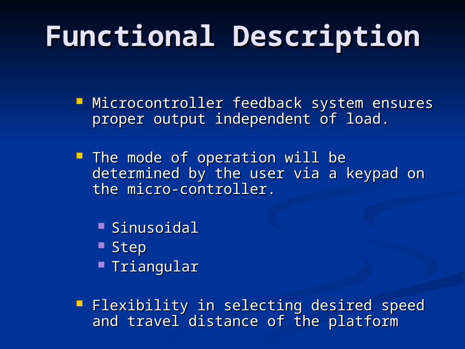
Functional DescriptionFunctional Description
Microcontroller feedback system ensures Microcontroller feedback system ensures proper output independent of load.proper output independent of load.
The mode of operation will be determined The mode of operation will be determined by the user via a keypad on the micro-by the user via a keypad on the micro-controller. controller.
SinusoidalSinusoidal StepStep TriangularTriangular
Flexibility in selecting desired speed and Flexibility in selecting desired speed and travel distance of the platformtravel distance of the platform
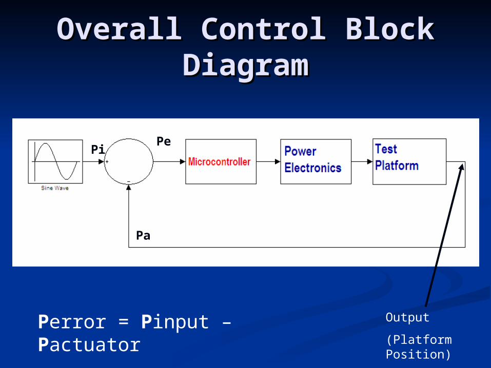
Overall Control Block Overall Control Block DiagramDiagram
Pe
Pa
Pi
Perror = Pinput – Pactuator Output
(Platform Position)
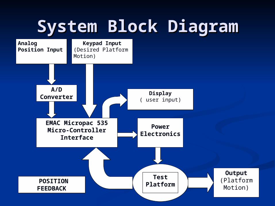
System Block DiagramSystem Block DiagramKeypad Input
(Desired Platform Motion)
Analog Position Input
EMAC Micropac 535Micro-Controller
Interface
A/DConverter
PowerElectronics
TestPlatform POSITION
FEEDBACK
Output(PlatformMotion)
Display( user input)
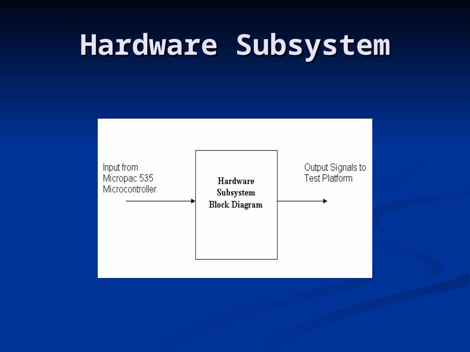
Hardware SubsystemHardware Subsystem
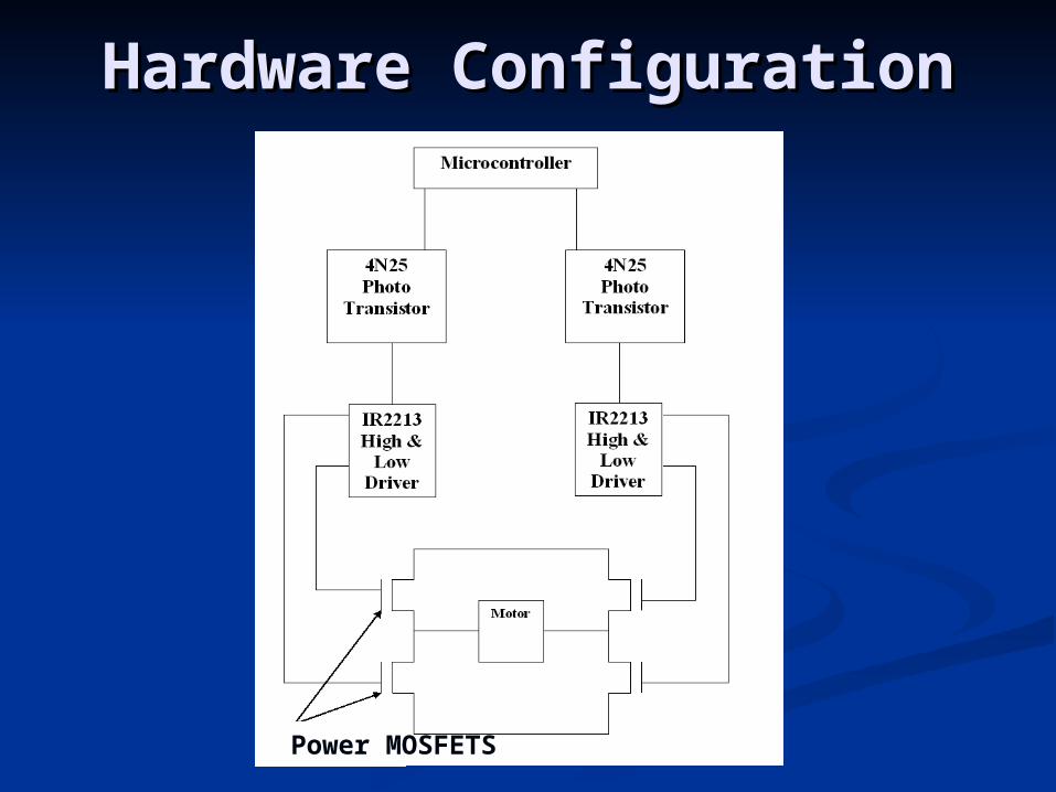
Hardware ConfigurationHardware Configuration
Power MOSFETS
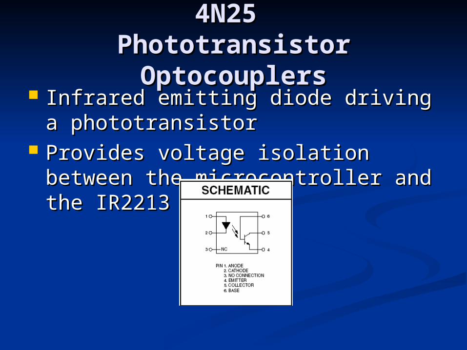
4N25 4N25 Phototransistor Phototransistor OptocouplersOptocouplers
Infrared emitting diode driving a Infrared emitting diode driving a phototransistorphototransistor
Provides voltage isolation between Provides voltage isolation between the microcontroller and the IR2213the microcontroller and the IR2213
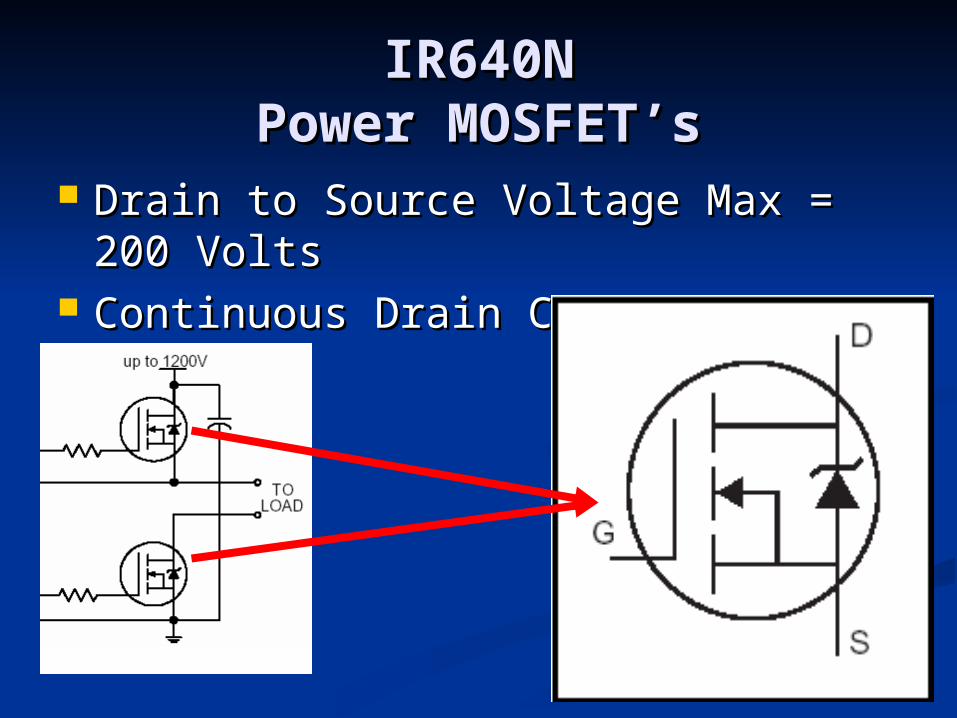
IR640NIR640NPower MOSFET’sPower MOSFET’s
Drain to Source Voltage Max = 200 Drain to Source Voltage Max = 200 VoltsVolts
Continuous Drain Current Max = Continuous Drain Current Max = 18A18A
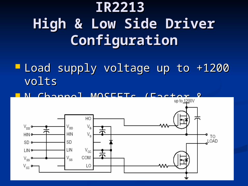
IR2213 IR2213 High & Low Side DriverHigh & Low Side Driver
ConfigurationConfiguration
Load supply voltage up to +1200 Load supply voltage up to +1200 voltsvolts
N-Channel MOSFETs (Faster & N-Channel MOSFETs (Faster & Cheaper)Cheaper)
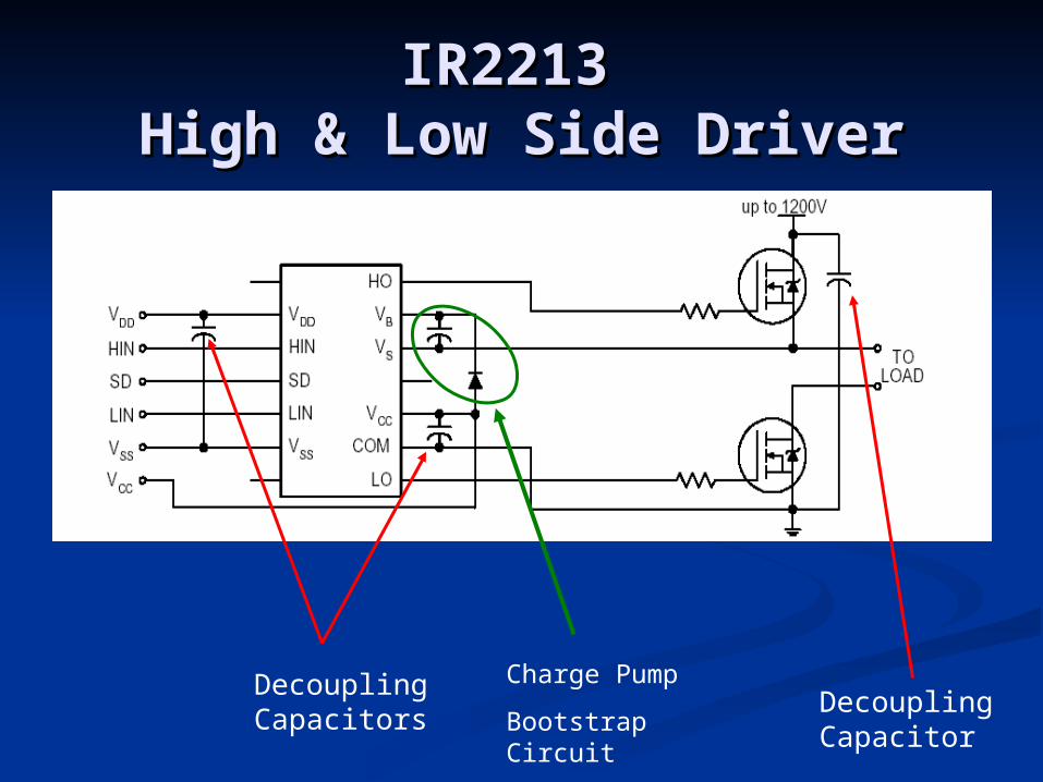
IR2213 IR2213 High & Low Side DriverHigh & Low Side Driver
Decoupling Capacitors
Decoupling Capacitor
Charge Pump
Bootstrap Circuit
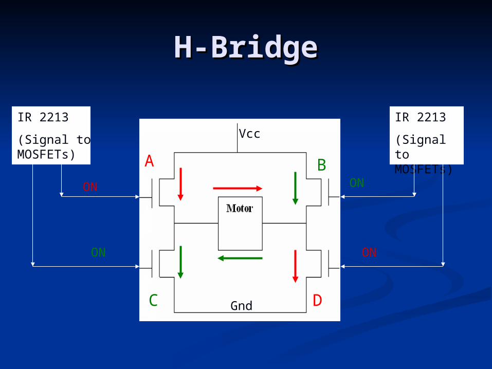
H-BridgeH-Bridge
Vcc
Gnd
A
D
B
C
IR 2213
(Signal to MOSFETs)
IR 2213
(Signal to MOSFETs)
ON
ON
ON
ON
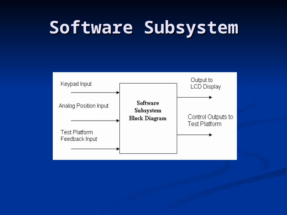
Software SubsystemSoftware Subsystem
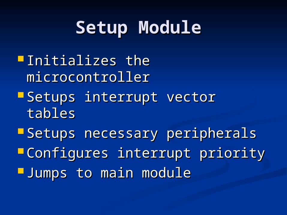
Setup Module Setup Module
Initializes the microcontrollerInitializes the microcontroller Setups interrupt vector Setups interrupt vector
tablestables Setups necessary peripheralsSetups necessary peripherals Configures interrupt priority Configures interrupt priority Jumps to main module Jumps to main module
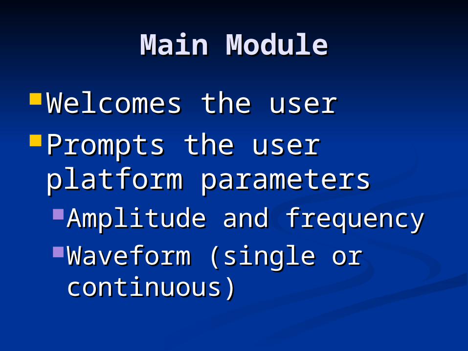
Main ModuleMain Module
Welcomes the user Welcomes the user Prompts the user platform Prompts the user platform
parametersparametersAmplitude and frequencyAmplitude and frequencyWaveform (single or Waveform (single or continuous)continuous)
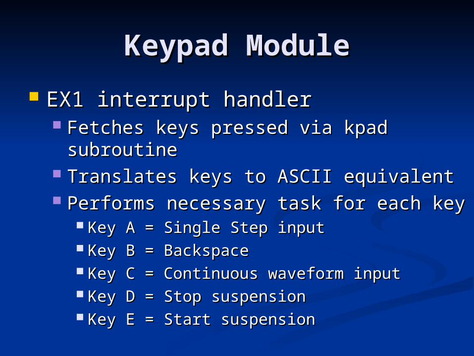
Keypad ModuleKeypad Module
EX1 interrupt handlerEX1 interrupt handler Fetches keys pressed via kpad subroutineFetches keys pressed via kpad subroutine Translates keys to ASCII equivalentTranslates keys to ASCII equivalent Performs necessary task for each keyPerforms necessary task for each key
Key A = Single Step inputKey A = Single Step input Key B = BackspaceKey B = Backspace Key C = Continuous waveform inputKey C = Continuous waveform input Key D = Stop suspensionKey D = Stop suspension Key E = Start suspensionKey E = Start suspension
Lcd ModuleLcd Module
Displays prompts Displays prompts
Displays user’s entriesDisplays user’s entries
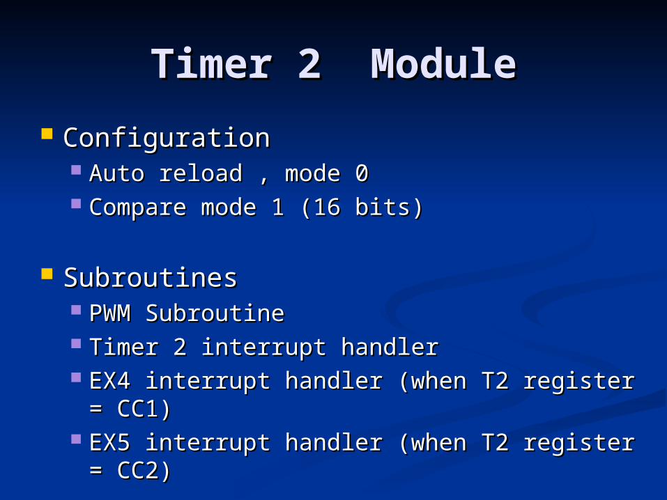
Timer 2 ModuleTimer 2 Module
ConfigurationConfiguration Auto reload , mode 0Auto reload , mode 0 Compare mode 1 (16 bits)Compare mode 1 (16 bits)
SubroutinesSubroutines PWM SubroutinePWM Subroutine Timer 2 interrupt handlerTimer 2 interrupt handler EX4 interrupt handler (when T2 register = EX4 interrupt handler (when T2 register =
CC1)CC1) EX5 interrupt handler (when T2 register = EX5 interrupt handler (when T2 register =
CC2)CC2)
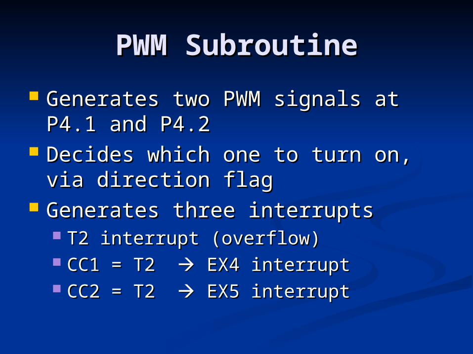
PWM SubroutinePWM Subroutine
Generates two PWM signals at P4.1 Generates two PWM signals at P4.1 and P4.2and P4.2
Decides which one to turn on, via Decides which one to turn on, via direction flagdirection flag
Generates three interruptsGenerates three interrupts T2 interrupt (overflow)T2 interrupt (overflow) CC1 = T2 CC1 = T2 EX4 interrupt EX4 interrupt CC2 = T2 CC2 = T2 EX5 interrupt EX5 interrupt
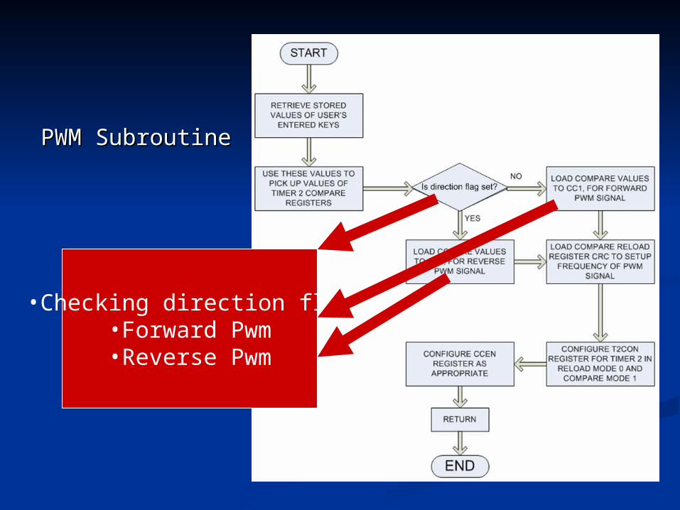
PWM SubroutinePWM Subroutine
•Checking direction flag•Forward Pwm•Reverse Pwm
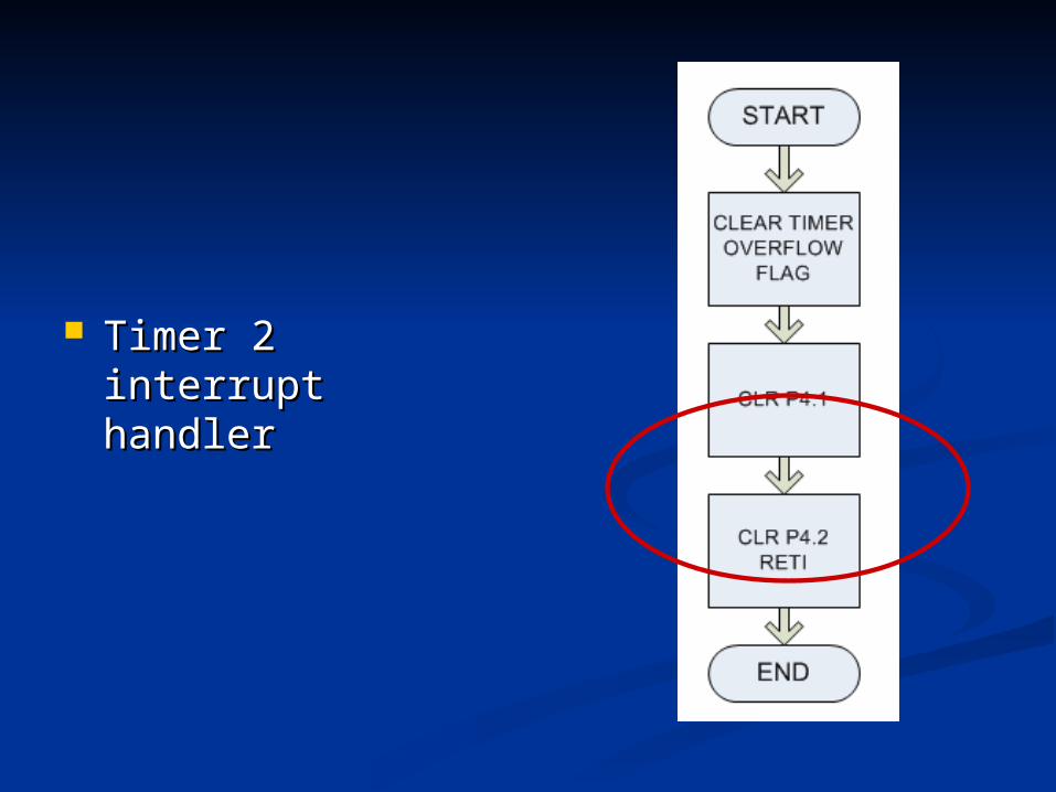
Timer 2 interrupt Timer 2 interrupt handlerhandler
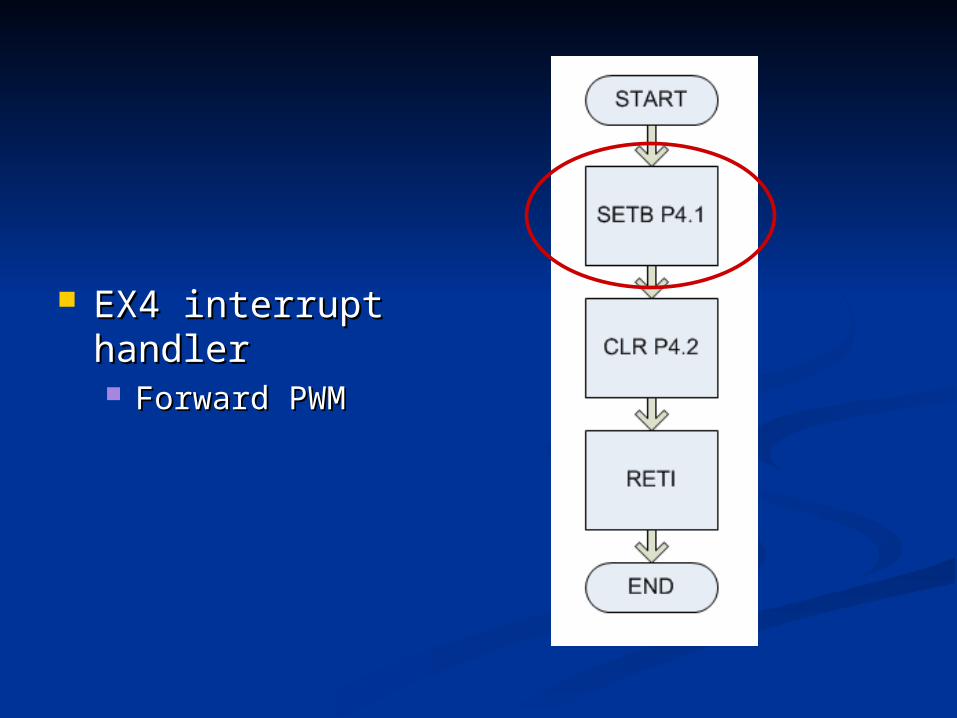
EX4 interrupt EX4 interrupt handlerhandler Forward PWMForward PWM
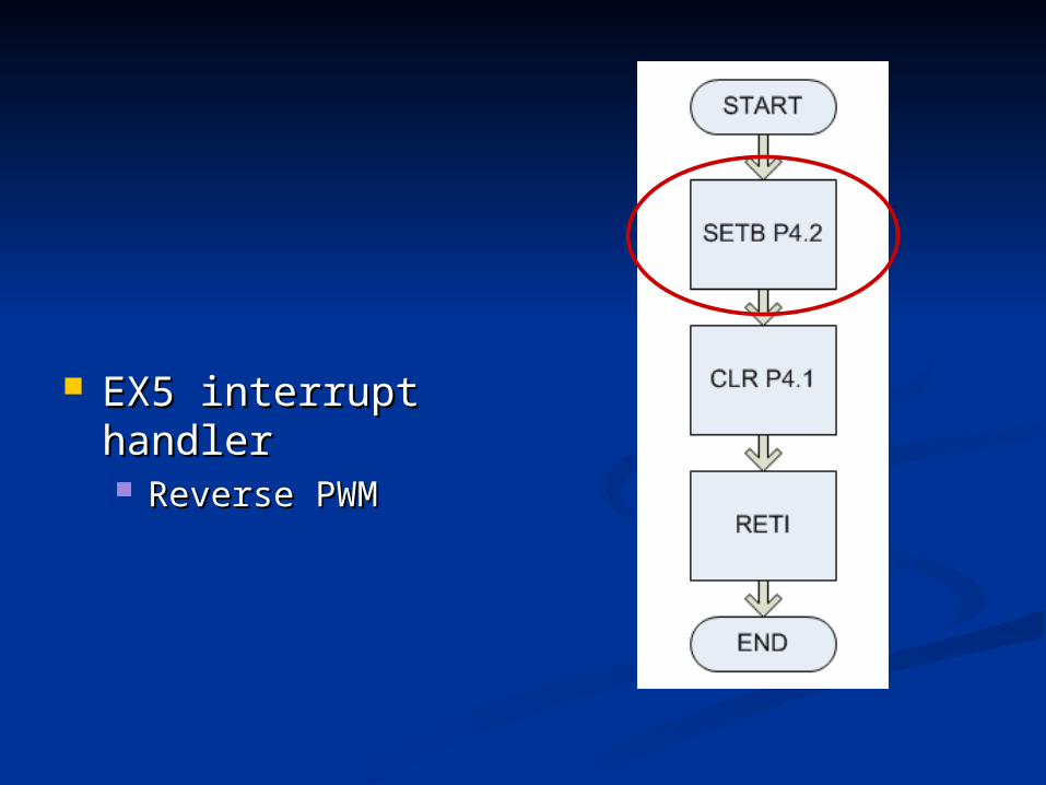
EX5 interrupt EX5 interrupt handlerhandler Reverse PWMReverse PWM
A/D ModuleA/D Module
Determines status of direction flagDetermines status of direction flag
A/D_piA/D_pi Fetches input signal from AN0Fetches input signal from AN0
A/D_paA/D_pa Fetches position feedback from AN2Fetches position feedback from AN2
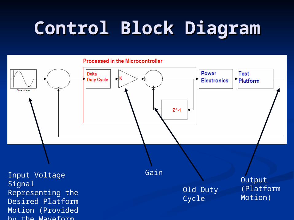
Control Block DiagramControl Block Diagram
Input Voltage Signal Representing the Desired Platform Motion (Provided by the Waveform Generator)
Output (Platform Motion)
Gain
Old DutyCycle
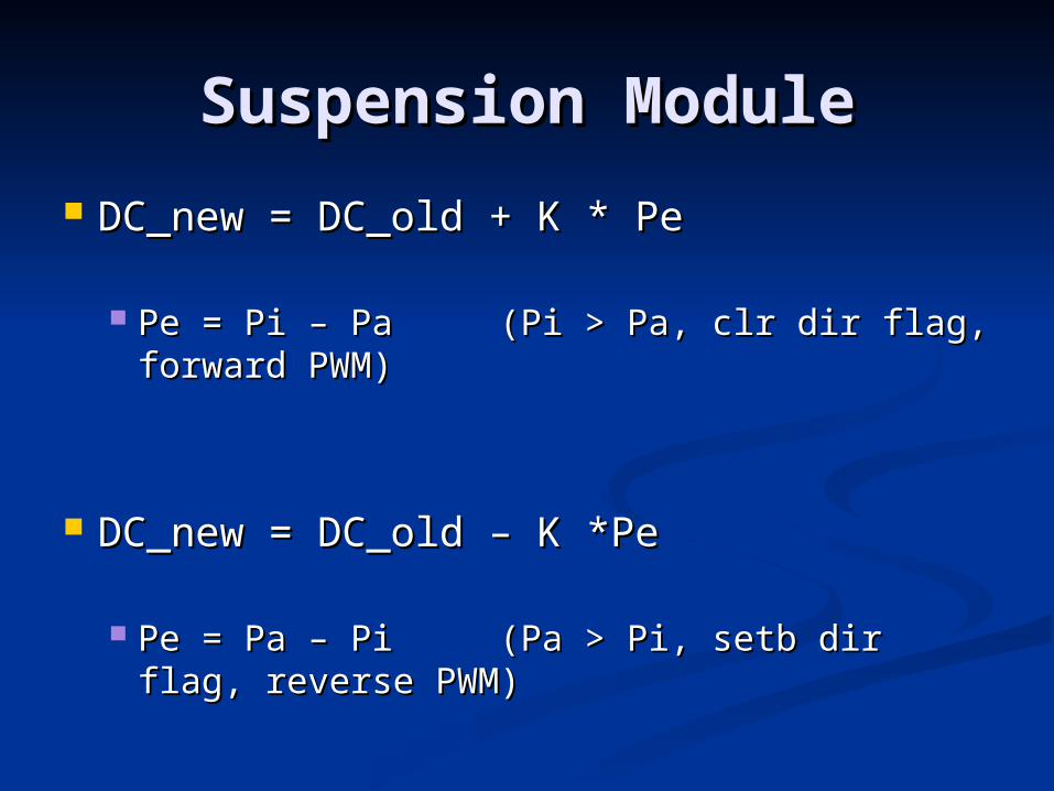
Suspension ModuleSuspension Module
DC_new = DC_old + K * Pe DC_new = DC_old + K * Pe
Pe = Pi – Pa (Pi > Pa, clr dir flag, forward Pe = Pi – Pa (Pi > Pa, clr dir flag, forward PWM)PWM)
DC_new = DC_old – K *Pe DC_new = DC_old – K *Pe
Pe = Pa – Pi (Pa > Pi, setb dir flag, reverse Pe = Pa – Pi (Pa > Pi, setb dir flag, reverse PWM)PWM)
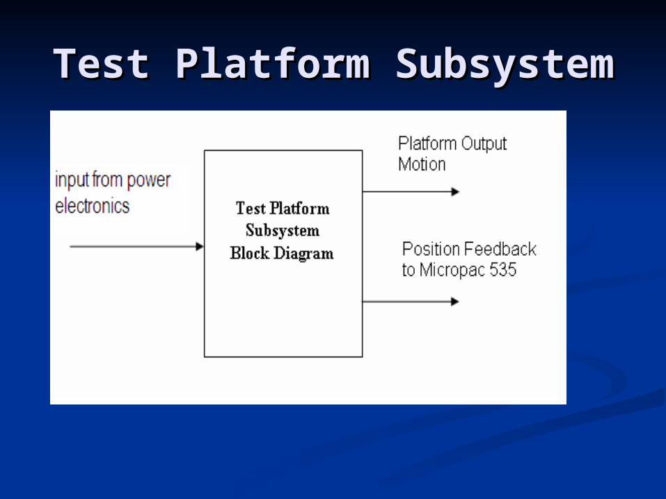
Test Platform SubsystemTest Platform Subsystem
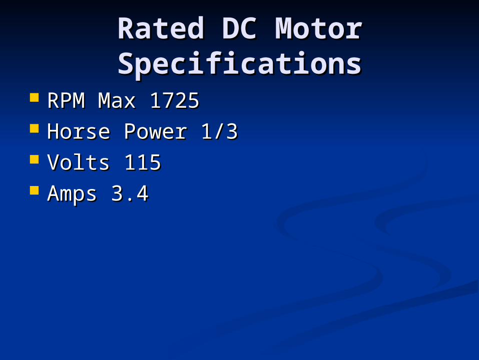
Rated DC Motor Rated DC Motor SpecificationsSpecifications
RPM Max 1725 RPM Max 1725 Horse Power 1/3Horse Power 1/3 Volts 115Volts 115 Amps 3.4Amps 3.4
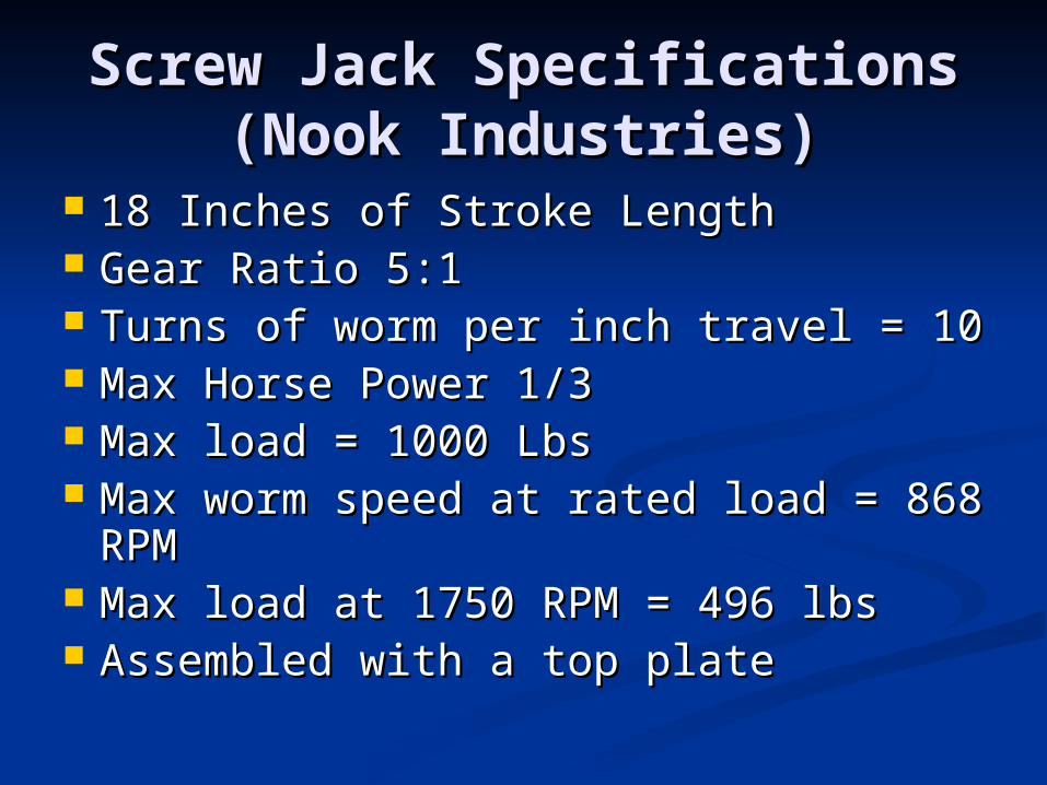
Screw Jack SpecificationsScrew Jack Specifications(Nook Industries)(Nook Industries)
18 Inches of Stroke Length18 Inches of Stroke Length Gear Ratio 5:1Gear Ratio 5:1 Turns of worm per inch travel = 10Turns of worm per inch travel = 10 Max Horse Power 1/3Max Horse Power 1/3 Max load = 1000 LbsMax load = 1000 Lbs Max worm speed at rated load = 868 Max worm speed at rated load = 868
RPMRPM Max load at 1750 RPM = 496 lbsMax load at 1750 RPM = 496 lbs Assembled with a top plateAssembled with a top plate
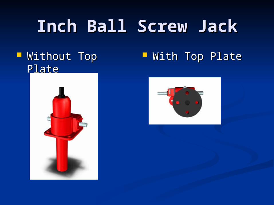
Inch Ball Screw JackInch Ball Screw Jack
Without Top PlateWithout Top Plate With Top PlateWith Top Plate
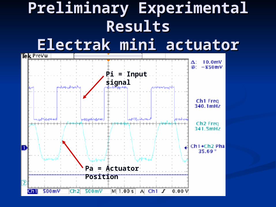
Preliminary Experimental Preliminary Experimental ResultsResults
Electrak mini actuatorElectrak mini actuator
Pi = Input signal
Pa = Actuator Position
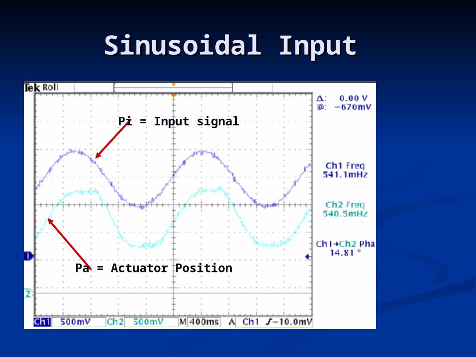
Sinusoidal Input Sinusoidal Input
Pi = Input signal
Pa = Actuator Position
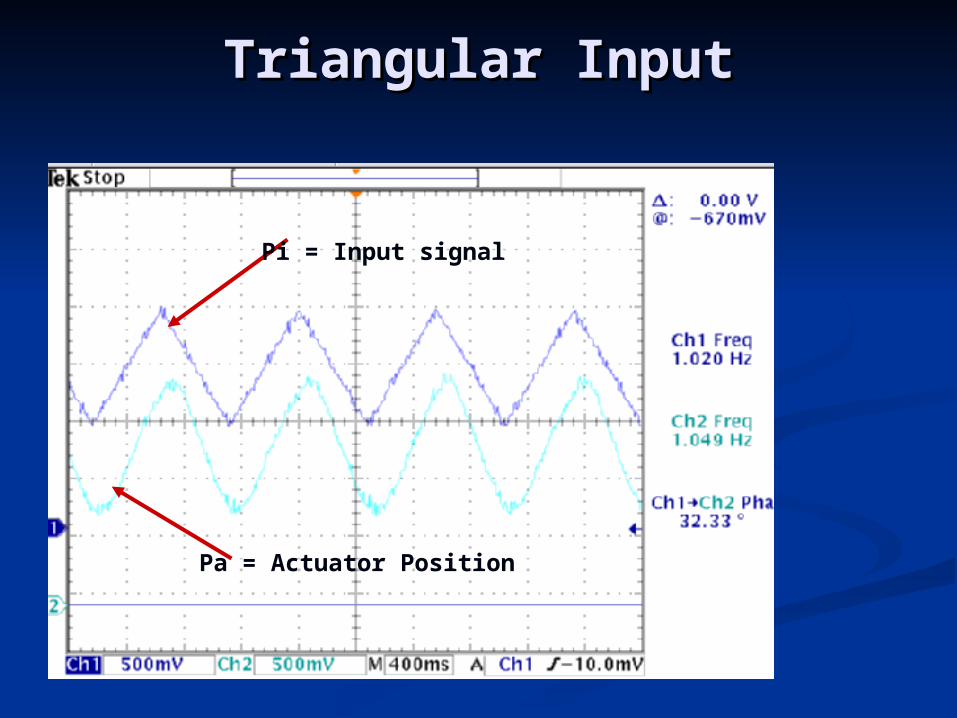
Triangular InputTriangular Input
Pi = Input signal
Pa = Actuator Position
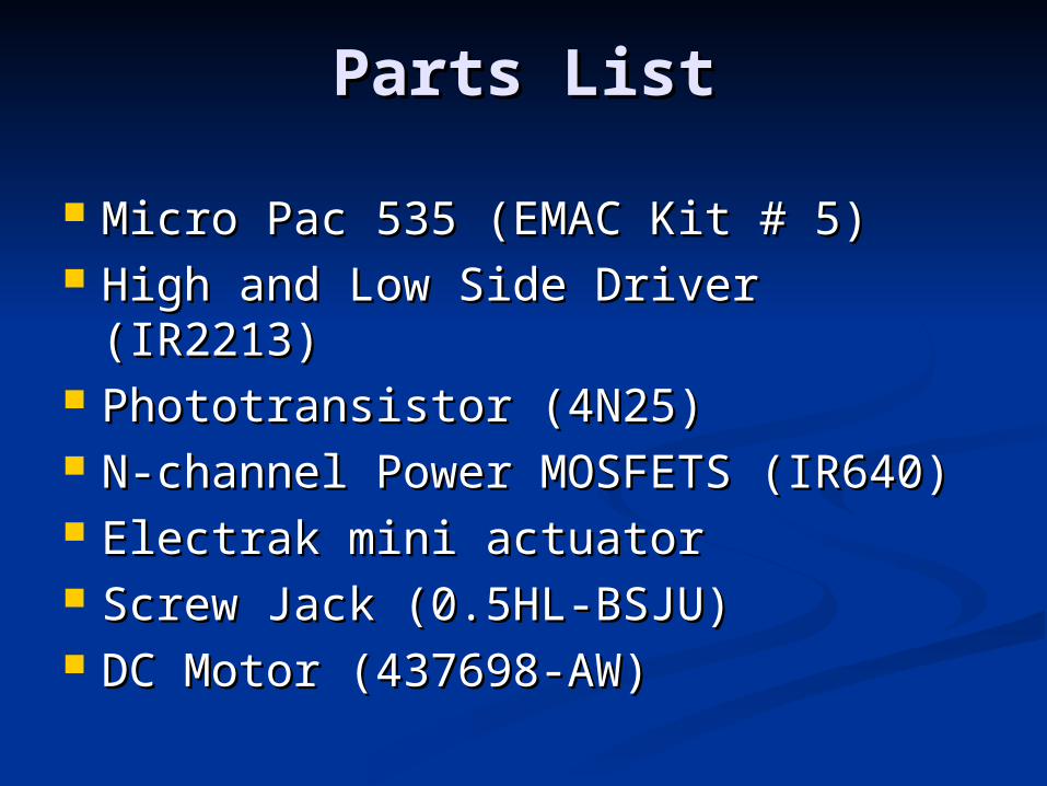
Parts ListParts List
Micro Pac 535 (EMAC Kit # 5)Micro Pac 535 (EMAC Kit # 5) High and Low Side Driver (IR2213)High and Low Side Driver (IR2213) Phototransistor (4N25)Phototransistor (4N25) N-channel Power MOSFETS (IR640)N-channel Power MOSFETS (IR640) Electrak mini actuator Electrak mini actuator Screw Jack (0.5HL-BSJU)Screw Jack (0.5HL-BSJU) DC Motor (437698-AW)DC Motor (437698-AW)

QUESTIONSQUESTIONS
??