active control of combustors after twenty years' efforts · air-breathing, turbomachinery, and...
TRANSCRIPT

ACTIVE CONTROL OF COMBUSTORSAFTER TWENTY YEARS£ EFFORTS
F. E.C. Culick and S. Palm
Active control of combustion was proposed by Bollay [1]. Following thatidea, Tsien [2] worked out an analysis of controlling low-frequency oscil-lations in a liquid rocket but no successful experimental results followed.More than thirty years passed before the ¦rst laboratory demonstra-tions were performed at Cambridge University. Interest grew rapidlyin the 1990s due to potentially wonderful applications to practical com-bustion systems including liquid and solid rockets, gas turbines, andthrust augmentors. Dreams have not materialized: There are presentlyno operational control systems, despite considerable e¨orts, and exam-ples of partially controlled phenomena. Only one practical installationfor control of oscillations has been documented, for a large Siemens ma-chine [3]. Its use has been rendered unnecessary by further experimentalwork leading to development of successful passive control with modi¦-cations of hardware [4]. The purpose of this paper is to examine brie§ysome of the reasons that active control of combustion has failed to be-come the panacea widely anticipated two decades ago. The authors£ viewis that the subject is far from exhausted, but rather requires carefullyplanned research to understand the basis of successful applications.
1 INTRODUCTION
Bollay£s original proposal that combustion systems could be actively controlledgrew out of his interests and work on feedback control of systems common toaeronautical applications. His suggestion was grounded in classical control the-ory. Although Bollay did not discuss this interpretation, his idea is capturedwith the block diagram shown in Fig. 1 [5] which shows a system controlled withpassive devices CG and CQ as well as feedback Cf and Cfb. The dynamics ofthe system are represented by G, and the dynamics of the combustion processesby Q.
By applying elementary rules for manipulating block diagrams, one can sim-plify the diagram of Fig. 1 to that shown in Fig. 2 representing the same dy-namical behavior F → P . All of the examples of linear systems discussed in
Progress in Propulsion Physics 1 (2009) 441-468DOI: 10.1051/eucass/200901441© Owned by the authors, published by EDP Sciences, 2009
This is an Open Access article distributed under the terms of the Creative Commons Attribution-Noncommercial License 3.0, which permits unrestricted use, distribution, and reproduction in any noncommercial medium, pro- vided the original work is properly cited.
Article available at http://www.eucass-proceedings.eu or http://dx.doi.org/10.1051/eucass/200901441

PROGRESS IN PROPULSION PHYSICS
Figure 1 Block diagram for a system containing passive (CG and CQ) and feedback(Cf and Cfb) control
this paper may be cast in this form if the ideas of classical feedback control arefollowed.What distinguishes control of combustion systems (the term ¢combustor£ is
usually equivalent to ¢combustion system£ in the present context) are mainly the¦ve attributes listed below:
(1) Internal instabilities;
(2) Substantial time lags;
(3) Intrinsic nonlinearities;
(4) High levels of noise; and
(5) The action of control changes properties of the system.
Not all of these attributes may be equally in§uential on the behavior of a givensystem, but the possibilities must be recognized.The primary motivation for considering feedback control was the common
occurrence of instabilities in all types of system. This is a physical phenomenon¢explained£ with the block diagrams of Figs. 1 and 2: Adding feedback (e.g., aresonating enclosure) to an ampli¦er (the combustion system) can produce anoscillator. It is nicely analogous, for example, to the situation when a laser oscil-lator is made by setting an amplifying medium (e.g., an appropriately preparedgas) inside an optical resonator formed by two mirrors.However, the really di©cult task is determining the basic cause of the in-
stability, the mechanism encapsulated by the ¦rst attribute (1). Maybe, thenone can do something about it so the system is stable under a broader range ofconditions. Unlike the common situation for traditional applications of feedback
442

AIR-BREATHING, TURBOMACHINERY, AND LAPCAT
control, the systems to be con-
Figure 2 General block diagram of a com-bustion system with passive and active control
trolled are almost always intrinsi-cally unstable, the reason for ap-plying control. Often unstablebehavior involves explicitly one ormore time lags, or can be formallydescribed in terms of time lags.A di©culty is soon encountered,that theories of feedback are lim-ited in respect to the ranges of dis-turbances that can be accommo-dated. Theories are quite limited when time lags are present, particularly, ifthe open loop system is unstable and contains more than one time lag.
Combustion systems are usually unstable in the absence of external forces;their motions therefore are limited by internal nonlinear e¨ects. Many conse-quences of nonlinear processes commonly appear in observed behavior. Nonlinearfeedback control is an undeveloped di©cult subject that has hardly been con-sidered for combustion systems. As a practical matter, linear feedback controlcan, of course, be used without regard for a system£s actual characteristic ¡ butpossible results cannot be anticipated.
It is probably true that the in§uences of noise can often be ignored withoutadverse consequences. However, certain details of observed behavior may requireaccounting for noise. A brief description based on one point of view has beengiven by Culick [5].
Probably the least understood factor, and perhaps the most signi¦cant ob-stacle to successful control of combustion systems, is summarized by the at-tribute (5). It is a possibility that has been largely overlooked in practicallyall the research reported to date, although examples have appeared in somedescriptions of experimental work. The ease with which the characteristics ofcombustion systems may change under both quasi-steady and truly dynamicalconditions is an enormous di¨erence compared with the situations for which clas-sical and modern feedback control were developed. The picture reproduced asthe third part of Fig. 7 below is one of the earliest evidences.
2 SOME EARLY RESULTS
Tsien£s example [2] is probably the simplest case illustrating several basic fea-tures of the problem. His idea was to control low-frequency oscillations called¢chugging,£ by varying a capacitance installed in the system (Fig. 3).
The equation for the chamber pressure, taken to be uniform throughout thevolume, is
443

PROGRESS IN PROPULSION PHYSICS
Figure 3 Schematic of the ¦rst proposal for active feedback control of the dynamicsin a combustion system [2]
d2p′
dt′+ 2α
dp′
dt+ ω20p
′ = βp′(t− τ) + u(t) (1)
where u(t) is an externally applied signal and βp′(t− τ) is the ¢feedback controlsignal£ (here, proportional to the delayed pressure p′(t − τ)). For oscillationshaving frequency ω, the Laplace transform of Eq. (1) gives
P (s) =βe−stG(s)
1− βe−stG(s)U(s) (2)
and
G(s) =1
s2 + 2αs+ ω20
is the transfer function for the system, which here is the pressure ¦eld in thechamber. The formula (2) is the response or ¢output£ of the system G(s) withthe feedback βe−st. These results can be represented with the feedback loopshown in Fig. 4.
Figure 4 Block diagram for the system shown in experiment
444

AIR-BREATHING, TURBOMACHINERY, AND LAPCAT
Figure 5 Feedback control of a Rijke tube by injection of acoustic waves: (a) emittedradiation as the sensed variable [6] and (b) pressure as the sensed variable with air forcedby a blower through the horizontal tube [7, 8]
Using a combination of the Nyquist criterion and Satche£s method for han-dling the exponential in Eq. (2), Tsien showed that the system could be stabilizedfor any value of the time lag τ . His conclusion prompted the ¦rst experimentsat the Aerojet Company, apparently either unsuccessful or inconclusive due toinadequate hardware and instrumentation.
Thirty years later in his Masters thesis, Dines [6] added simple instrumenta-tion to a Rijke tube and carried out the ¦rst laboratory tests of active control ofa combustion system. His apparatus is sketched in Fig. 5. In her Ph.D. researchand subsequently, Heckl [7, 8] built on Dines£ work and executed the earliestextended series of tests, using the apparatus sketched in Fig. 5b.
The works by Dines and Heckl were the primary experimental bases for theU.S. Patent [9]. That document is a good description of their ideas for applyingthe method to both the primary combustor and the thrust augmentor of a gasturbine. It is probably the ¦rst discussion of the main elements of an activecontrol system for a controller as conceived by the Cambridge group. At thattime, the di©culties in making such a control system actually work with anactual combustor were yet to be discovered. The proposal covered in the patentis foresighted in two respects not actually accomplished for about 8�9 years: The
445

PROGRESS IN PROPULSION PHYSICS
Figure 6 Cambridge apparatus: (a) ¦xed nozzle for studies of longitudinal instabil-ities [10] and (b) variable nozzle for experiments to determine transfer functions andfor active control [11]
authors proposed that control be exerted by modulation of the fuel supply; andthat a multiinput, multioutput (MIMO) system would be required.Immediate subsequent research at Cambridge produced interesting results
obtained from the apparatus sketched in Fig. 6. The work was performed underthe supervision of Prof. Dowling with ¦nancial support by Rolls Royce as partof their e¨ort to reduce the consequences of oscillations in thrust augmentors.In their program, the Cambridge group were ¦rst to investigate actuation bymodulating the fuel supply, proposed in the patent [9]. This clearly is a morepractical method than one based on loudspeakers, as shown in Fig. 5, and is nowuniversally used except for simple demonstrations.Some time later, a modest demonstration of control of an instability in an
augmentor was reported in [12]. The apparatus was clearly special, and the workdid not generate further experimentation following the same approach.At about the same time, an interesting research program was initiated in the
combustion laboratory at ‚Ecole Centrale, Paris, in collaboration with a groupat the Technische Universit�at M�unchen. The greater part of the collaborativeprograms was reported by Lang et al. [13], and by Poinsot et al. [14, 15]. Figure 7
446

AIR-BREATHING, TURBOMACHINERY, AND LAPCAT
Figure 7 Feedback control at ‚Ecole Centrale (a) apparatus with a 250-kilowattcombustor; (b) e¨ects of control on the sound emission; and (c) Schlieren photographsof the combustion region (i) without and (ii) with control [14, 15]
shows their apparatus and, for the purposes here, their most signi¦cant results.Figure 7b shows the signi¦cant e¨ect of control, here executed by the action ofloudspeakers, on the spectral amplitude function of the oscillations. That resultis fairly typical of the ¦ndings reported by a number of groups in the late 1980sand 1990s. Note that the most intense component of the spectrum has beenreduced by about 20�25 dB.
447

PROGRESS IN PROPULSION PHYSICS
Most noteworthy is Fig. 7c. The photograph is perhaps the ¦rst evidence thatcontrol of oscillations may have substantial e¨ect on both the average and un-steady distributions of combustion. It is by no means clear what the e¨ects were,but there are undeniable di¨erences in the schlieren photographs of the com-bustion zones in the uncontrolled (Fig. 7c, i) and controlled states (Fig. 7c, ii).Other pictures of similar phenomena observed in di¨erent experiments have beenpublished; this early result already seems to make the point well.
3 OPERATIONAL ACTIVE CONTROL SYSTEM
With the exception of the theoretical discussions in the patent [9] and analysesby Fung et al. [16, 17], virtually all results obtained for control of combustionwere worked out for gaseous systems until the mid-1990s∗. Several doctoralprograms at the Technische Universit�at M�unchen had signi¦cant consequencesfor applications to control of liquid-fueled systems.
Figure 8 Feedback control at Technische Universit�at M�unchen: (a) apparatus and(b) the piezo actuator [20]
∗Small e¨ects of a modulated supply of liquid fuel had been noted in a patent applicationby Gulati and Bigelow [18].
448

AIR-BREATHING, TURBOMACHINERY, AND LAPCAT
Figure 9 Test results obtained with the apparatus shown in Fig. 8 and Fig. 14 of [20]
The work was preceded by earlier research not covered here, but the resultsmost directly in§uential in the subjects discussed in this way were reported inthe papers [19, 20]. Probably their most important contribution is the use of apiezo-electric actuator to modulate all or a portion of the fuel. Sketches of theirlaboratory apparatus and actuator are given in Fig. 8; an example of attenuationof oscillations is reproduced in Fig. 9.
A really interesting ¡ and instructive! ¡ consequence of the research inM�unchen was that the work led directly, and surprisingly quickly, to develop-ment of a system adopted for use in large operational Siemens gas turbines.Moreover, they were, and apparently remain, the only MIMO control systemsdeveloped for combustors. The hardware, and experience in practice, are well-described in [21]; details of the control system were reported by Hermann etal. [3, 21]. Control systems were eventually installed on fourteen V94.3A gasturbines, each used in a 270-megawatt electric power generation unit. Two ofthe machines accumulated a total greater than 140,000 hours of operation withno failure.
449

PROGRESS IN PROPULSION PHYSICS
Figure 10 Addition of the cylindrical burner outlet (CBO) to the Siemens HybridBurner [4]
The story ends dramatically, if not happily for those desiring practical usageof feedback control. Continuing e¨orts by engineers at Siemens at last locatedthe mechanism for the instability. Apparently, interactions at the inlet for thefuel supply initiated and sustained acoustic waves, whose principal motions were(roughly) in directions not including that of the average axial §ow. Additionof a ¦tting to the burner outlets (Fig. 10) was the main e¨ective modi¦cation.Misalignment of a few burner supply nozzles also aided suppression of the in-stability by destroying azimuthal symmetry. The net result was that the activecontrol system was reportedly eliminated from operational use.
4 RESEARCH ON ACTIVE CONTROLOF COMBUSTION, 1990�PRESENT
As national and international regulations governing emissions became increas-ingly stringent for both transportation and stationary powerplants, attention wasdirected to combustion at lower temperatures. The reason is shown in Fig. 11.It is a basic result that formation of nitrogen oxides is favored by high tem-peratures, established by Zel£dovich [23] and con¦rmed beyond doubt by manyexperimental measurements.That simple fact motivated and has dominated research in combustion dy-
namics for two decades. The drive towards lean combustion has forced design ofcombustors which, operating near the lean limit, are ever closer to their stabilitylimits. Sources of the instabilities are intrinsic to any system and simply can-
450

AIR-BREATHING, TURBOMACHINERY, AND LAPCAT
Figure 11 Concentrations at equilibrium of carbon monoxide and oxides of nitro-gen [22]
not be designed away in any obvious fashion. For example, §uctuations of §owvelocity and mixture ratio associated with §ow past edges (as during injection),or separation and recirculation at steps or ¢corners,£ become naturally ampli-¦ed under lean conditions. Boundary layers, inevitably turbulent, may developand shed vortices which interact with the main §ow and grow by extraction ofenergy.Discovering what processes are active in a given design, and their relative
importance as operating conditions change, presents horribly complicated ex-perimental problems in actual combustors. Applications of computational §uiddynamics (CFD) have grown considerably in the recent past ¡ see, for example,several articles in the volume edited by Lieuwen and Yang [24]. Capabilities forstudying stability of combusting §ows in actual con¦gurations remain beyondreach at present.Thus, it is not surprising that almost all of the work in this ¦eld has been
experimental, or perhaps better put, demonstrational. Following the works dis-cussed in Section 2, activity in the area increased greatly in both the U.S. andEurope. The report of a workshop sponsored by AGARD [22] gives a good sum-mary of the state of the ¦eld in 1996. Mainly topics of interest to the aerospacecommunity were covered. The recent collection of papers compiled by Lieuwenand Yang [24] is the most thorough survey of problems arising in combustionsystems for gas turbines.
451
PROGRESS IN PROPULSION PHYSICS
Lesser e¨orts have continued mainly in three other directions which may beidenti¦ed roughly as belonging to three separate classes:
(i) afterburner (thrust augmentor) instabilities;
(ii) high frequency motions or instabilities in solid rockets; and
(iii) control of lean blowout (LBO) in gas turbines. Little interest has beenshown in actively controlling instabilities in liquid rockets.
Research activities directed to use of feedback control may be divided quali-tatively into three types:
(i) those which emphasize the control aspects;
(ii) those dominated by the physical character of the dynamical motions beingstudied; and
(iii) those which consciously attempt to merge the ¦rst two.
It is impossible to separate the control problems entirely from the physicalbehavior of the system under consideration, but much of the work carried out inthe past 10�15 years has tended to emphasize methods of control which had beendeveloped previously for systems not involving §ow or combustion. Applicationsof those methods, perhaps in modi¦ed form, have tended to proceed withoutspecial attention to attributes of the systems being studied.The largest and most successful research activity in this area in the U.S.
has been carried out at Georgia Tech beginning in the mid-1990s (see, e.g., [25,26]). Two dominant themes have guided the work which is in a sense a naturalextension and elaboration of the Cambridge approach but applied to liquid-fueled gas turbines: development of a fast ¢observer,£ i.e., digital identi¦cation ofdetailed properties, such as the spectral components of an instability; and use ofa new form of magnetostrictive actuator used to modulate a secondary supplyof fuel. The program is summarized well in the recent useful review by Prof.Zinn [26]. A patent issued to Neumeier and Zinn [27] contains descriptions ofmuch of the technical content of the Georgia Tech work. Figure 12 is a schematicsummary of the main achievements.The doctoral dissertation by Johnson [28] is a useful introduction to the
Georgia Tech work, particularly the more recent e¨orts in adaptive control.Practical di©culties in the applications of automated control long ago led tothe idea of building into a system some means of compensating ¡ without ex-ternal intervention ¡ for changes in the environment or in the system itself.That is broadly the character of adaptive control. Presented with the di©cul-ties and basic uncertainties in the physical characteristics of the systems, thoseworking in this ¦eld very early explored the possibilities presented by adap-tive control. ’Astrom and Wittenmark [29] have given a comprehensive and
452

AIR-BREATHING, TURBOMACHINERY, AND LAPCAT
Figure 12 Schematic of Georgia Tech method of active control [26]
useful text covering the ¦eld. They do not discuss §uid or combustion sys-tems.Billoud et al. [30] ¦rst studied the use of adaptive control in the present con-
text. The subject was pursued in greater depth by Evesque et al. [31�33]. Thepublications on the subject have mainly covered applications based on estab-lished procedures using methods worked out for applications in electrical engi-neering. Quite simple treatments of the combustion and §ow ¦elds have servedfor illustrative purposes.There is a large number of papers dealing with various observations and
experiments directed to special aspects of the general ¦eld, control of com-bustion dynamics. Some, such as Lieuwen et al. [34], are intended to estab-lish details of mechanisms, but usually not under conditions closely approxi-mating those in operational combustors. In particular, the geometries arealmost always simpli¦ed in the interests of isolating particular features. Ex-perience, for example, with instabilities in solid rockets suggests that may notalways be a wise tactic (see [5] for an extended coverage of experiences in thatarea).As the last example, a short discussion of some aspects of instabilities and
their control in full-scale combustors is given for two contrasting types of opera-tional designs. It has not been possible yet to obtain copies of all early relevantreferences, so parts of the story are based on word-of-mouth information. Inbroad outline, the story is certainly true.In the 1970s, NASA sponsored the Experimental Clean Combustor Program
(ECCP) ¤directed toward the development and experimental engine evaluationof the technology required to reduce pollutant emissions for both current and
453
PROGRESS IN PROPULSION PHYSICS
future gas turbine engine combustors¥ [35]. There were two participants inthe three-phase program: General Electric (GE) modi¦ed the combustor fortheir engine CF6-50 which was used, for example, in Boeing 747 aircraft; andPratt and Whitney (P&W), after preliminary work in the ¦rst two phases of theprogram, used their new experimental design called the Vorbix combustor ¦ttedto a JT9D-7A engine in Phase III.The ¦nal reports of Phase III [35, 36] document the results of the programs.
What matters here are the broad conclusions drawn with the help of thirtyyears£ progress since the ECCP: The GE research in ECCP was the beginningof lengthy developments leading to several forms of lean premixed (LP) or leanprevaporized, premixed (LPP) and lean direct injection (LDI) combustors incurrent use. Lean prevaporized, premixed combustors are generally in use asaeroengine derivatives for the industrial or land based gas turbines, whereas LPand LDI combustors are being developed for aeroengine applications.In the discussions below, these combustors will be called ¢lean.£ P&W re-
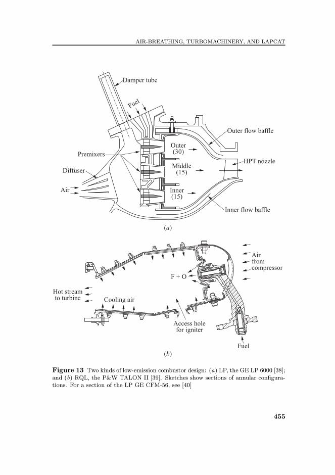
search has led to the Technology for Advanced Low Nox (TALON) series ofcombustors, which are installed in all combustors which are recently certi¦edor are under development at P&W. As Sabnis [37] has described, the TALONcombustors are based on the rich-quench-lean (RQL) idea for reducing emissions.Examples of the two types of combustor design are shown in simpli¦ed forms
in Fig. 13. Note that quarter-wave tubes as acoustic dampers are integral to theGE design of the LM 6000. Moreover, a kind of active control is used, a formof parametric control [38]. That is, there is no actuation at high frequencies,but stable operation is maintained by ¢slow£ changes of parameters governingthe operating state of the chamber.The principle on which the lean combustion designs are based was explained
earlier. In a general sense, conditions are not far from equilibrium as the §owprogresses through the chamber. Quite di¨erently, nonequilibrium (the ¢quench£)is an essential step in §ow through an RQL combustor.But in return for being forced to deal with a fundamentally more compli-
cated §ow ¦eld, look at the simple mechanical design one gets! Already with theVorbix, an example of early RQL combustors, certain goals were set for the pro-gram. The P&W engine with the Vorbix combustor produced oxides of nitrogen10% below the goal; carbon monoxide 25% below the goal; and total unburnedhydrocarbons 75% below the goal. Great results, but the smoke emissions failedto meet the requirements.There were several other de¦ciencies. The net result was that many people,
including those making decisions at GE, evidently concluded that the Vorbix orRQL, or other sorts of ¢nonequilibrium£ combustors, did not o¨er a good basis fordevelopment. Oxides of nitrogen, carbon monoxide, and unburned hydrocarbonswere reduced respectively by 30%, 55%, and 95% for the modi¦ed CF6-50 engine,with ¤acceptable smoke levels.¥ The combustor was an early lean design (a ¤dualannular combustor¥ or DAC) which has been highly developed since. The dry
454
AIR-BREATHING, TURBOMACHINERY, AND LAPCAT
Figure 13 Two kinds of low-emission combustor design: (a) LP, the GE LP 6000 [38];and (b) RQL, the P&W TALON II [39]. Sketches show sections of annular con¦gura-tions. For a section of the LP GE CFM-56, see [40]
455
PROGRESS IN PROPULSION PHYSICS
low emissions combustor (Fig. 13a) is one form having three arrays of injectors,and Fig. 13b shows the P&W TALON II.The great de¦ciency of lean combustors is of course the inevitable problem
with combustion instabilities. Whether that is the reason P&W chose the RQLroute we do not know at this time, but it was a magni¦cent decision. Eventually,all emissions requirements were met, and as a signi¦cant secondary bene¦t, therelative simplicity of the TALON design is apparent from comparison of Fig. 13b,on the one hand, with Fig. 13a and the LP design of the GE CFM-56 [40], onthe other. Development of the TALON series continues, but just how far theemissions can be reduced is not yet understood. It must be emphasized also thatunder suitable conditions, TALON combustors will have instabilities, but thatproblem is substantially less severe than in lean combustors.For all combustor designers, the prospect of combustion instabilities and
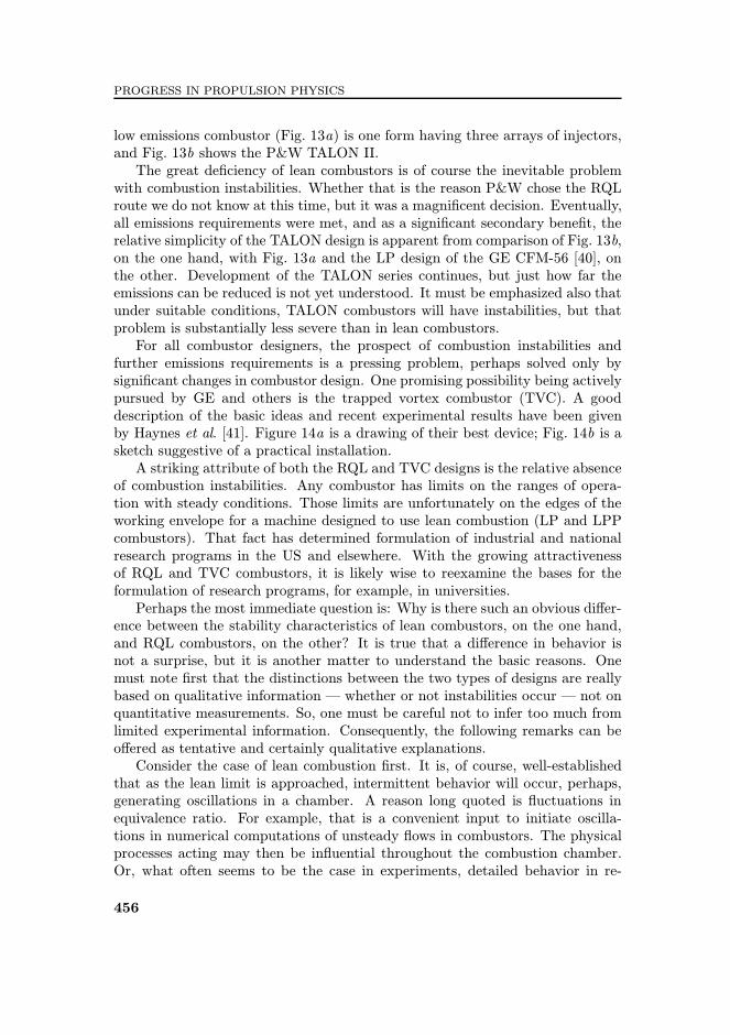
further emissions requirements is a pressing problem, perhaps solved only bysigni¦cant changes in combustor design. One promising possibility being activelypursued by GE and others is the trapped vortex combustor (TVC). A gooddescription of the basic ideas and recent experimental results have been givenby Haynes et al. [41]. Figure 14a is a drawing of their best device; Fig. 14b is asketch suggestive of a practical installation.A striking attribute of both the RQL and TVC designs is the relative absence
of combustion instabilities. Any combustor has limits on the ranges of opera-tion with steady conditions. Those limits are unfortunately on the edges of theworking envelope for a machine designed to use lean combustion (LP and LPPcombustors). That fact has determined formulation of industrial and nationalresearch programs in the US and elsewhere. With the growing attractivenessof RQL and TVC combustors, it is likely wise to reexamine the bases for theformulation of research programs, for example, in universities.Perhaps the most immediate question is: Why is there such an obvious di¨er-
ence between the stability characteristics of lean combustors, on the one hand,and RQL combustors, on the other? It is true that a di¨erence in behavior isnot a surprise, but it is another matter to understand the basic reasons. Onemust note ¦rst that the distinctions between the two types of designs are reallybased on qualitative information ¡ whether or not instabilities occur ¡ not onquantitative measurements. So, one must be careful not to infer too much fromlimited experimental information. Consequently, the following remarks can beo¨ered as tentative and certainly qualitative explanations.Consider the case of lean combustion ¦rst. It is, of course, well-established
that as the lean limit is approached, intermittent behavior will occur, perhaps,generating oscillations in a chamber. A reason long quoted is §uctuations inequivalence ratio. For example, that is a convenient input to initiate oscilla-tions in numerical computations of unsteady §ows in combustors. The physicalprocesses acting may then be in§uential throughout the combustion chamber.Or, what often seems to be the case in experiments, detailed behavior in re-
456

AIR-BREATHING, TURBOMACHINERY, AND LAPCAT
Figure 14 The TVC: (a) a sketch of the combustor use in GE work [41] and (b) anotion suggestive of a possible axisymmetric installation (AFRL release)
gions near surfaces, or in corners and around obstacles may be responsible. Un-steady viscous e¨ects, causing §uctuations of composition and mixture ratio,locally can be signi¦cant. Small changes become relatively more important asthe average equivalence ratio is reduced. Fluctuations of §ame speed due tothe §uctuations of composition may combine with other compositional e¨ectsto encourage §ame ¢blowout.£ Whatever may be the details, the main result isa general weakening of the processes responsible for anchoring the §ame. Note
457

PROGRESS IN PROPULSION PHYSICS
the general characteristic that purely §uid mechanical processes are centrallyimportant.
In an RQL combustor, such e¨ects are absent, or at worst much reduced,in the rich region near the head end where injection of the combustible mixtureoccurs. Further downstream where e¨ects similar to those found in lean combus-tors may occur, the e¨ects on overall §ame stability are considerably reduced,because much of the §ame region is stabilized already by the processes in therich region. Because of the general nature of the combustion processes in thechamber taken as a whole, the reaction processes are relatively more smearedout in the RQL combustor. The fact that the RQL combustor is in some generalsense more of a nonequilibrium system than is a lean system, is a fundamentalreason for the striking di¨erences in stability.At this time, then, the two types of combustor are quite well-de¦ned. Their
respective limits of performance are not so well established. On balance, however,it appears that combustors operating with premixed lean reactants are betterunderstood than RQL or related devices depending in fundamental ways onnonequilibrium processes. Probably, the ¢return-on-investment£ in research ispotentially much greater for the second class of devices.
5 SOME EXPERIMENTAL RESULTS
Determining the lower limits on emissions for a given combustor design is a verytedious and imprecise process, particularly, if it is carried out empirically withtests of the full-scale device. A similar situation prevails for establishing thestability limits. It is a fundamental obstacle to formulating design guidelinesand procedures that surprisingly little attention has been paid to certain basicproblems that must be better understood to achieve further progress. Consideredbrie§y in this section is one modest example related particularly to a possiblemechanism for combustion instabilities in lean combustors.
A complete formulation of the problem of instabilities shows explicitly thatthe frequency response of combustion processes is a fundamental factor. In thecase of solid propellant rockets, approximate analyses in the 1950s showed thatthe admittance function for a burning surface has behavior dominated underpractical conditions by unsteady heat conduction in the solid phase. The fre-quency response of the surface consequently is ampli¦ed in a frequency rangewhich also captures many acoustic modes for practical rocket combustors, a fewhundred to several thousand hertz.
Much e¨ort, and money, has been spent as workers in many countries haveattempted to gain necessary information about the responses (¢admittance func-tions£) for actual propellants. The ¦eld is still active as practical problems con-tinue to arise, and fundamental problems remain. There seemed reason to expect
458

AIR-BREATHING, TURBOMACHINERY, AND LAPCAT
that similar processes would likely be active in gas-turbine combustors. The re-search described in this section was initiated to investigate the question.An unexpressed, but surely implied, hope (expectation?) accompanying the
introduction of feedback control as a means of combating instabilities in gas-turbine combustors, was that the dreadful obstacles encountered with problemsof stability similar to that in solid rockets would be avoided. The magic offeedback would do the job. That kind of sanguine view may have had much todo with the character of research funded in the ¦eld for two decades. But itseems that the unsatisfactory state of success and lack of recent progress maysuggest that there is no substitute for understanding the problems that are basicto the ¦eld.In the middle to late 1990s, laser-based methods became available to inves-
tigate the time and spatial characteristics of distributed combustion processes.Building on early works [42, 43], a program was initiated at Caltech to meas-ure the frequency response of §ames at atmospheric pressure. There were twoprincipal methods available at that time: (i) passively observed chemilumines-cence and (ii) planar laser induced §uorescence (PLIF). The great advantage ofPLIF, which is far more di©cult to use and requires relatively expensive spe-cial equipment and data processing, is that it o¨ers unmatched opportunitiesfor spatial and temporal resolution. For extended explanatory coverage, see twoPh.D. dissertations [43, 44] as well as several published papers.Sketches of the apparatus used for the two di¨erent sorts of experiments are
given in Fig. 15. In both cases, §ames are immersed in steady acoustic ¦elds.The geometries used, and frequency ranges covered, are such that the §ames areexposed to uniform oscillating pressure ¦elds. In support of the main conclusiongiven below, some results obtained with observations of chemiluminescence froma §at methane §ame are brie§y discussed.Chemiluminescence is measured using a photomultiplier tube coupled to a
Nikon F/1.2 lens which views the §ame through one of the side windows of thetest section. An optical band-pass ¦lter is used to reject all incoming light ex-cept that associated with CH and CO2 chemiluminescence. The photomultipliertube (PMT) signal is fed to a transimpedance preampli¦er which provides gainand also separates the alternating current (AC) and direct current (DC) signalcomponents. The DC component, which represents the average heat §ux to the§ame, q, is fed directly back to the data acquisition (DAQ) computer and ismeasured. The AC component, which represents q′, is fed to an EG&G dual-phase lock-in analyzer. This unit uses the oscillator signal from the AFC-100as its reference input and measures the magnitude and phase of the q′ signal.The lock-in analyzer has substantial sensitivity and noise rejection capabilityand, in this experimental con¦guration, is capable of resolving q′/q ratios downto 10−7.Once all the data is returned to the DAQ computer, it is used to calculate
one point of the combustion response function:
459

PROGRESS IN PROPULSION PHYSICS
Figure 15 Experimental con¦gurations used for measurements of the frequencyresponse of combustion regions: (a) chemiluminescence and (b) PLIF
460

AIR-BREATHING, TURBOMACHINERY, AND LAPCAT
H(s) =q′(s)p(s)
q(s)p′(s); s = jω .
This combustion response function from 20 to 1800 Hz is synthesized bycontinuously repeating this operation while the drive frequency is swept. Thisentire operation is fully automated.
The burner currently being tested is a blu¨-body stabilized, §at-§ame burner.In this device, premixed methane and air pass through a converging nozzle,leaving the nozzle exit as a free jet. This jet impinges upon a water cooledstagnation plane, oriented normal to the direction of §ow. The diameter of thejet at the nozzle exit is 14 mm and the nozzle shape is designed to produce atop-hat velocity pro¦le at this location.
As the jet approaches the stagnation plane, the axial velocity decreases whilethe radial velocity increases. The §at §ame is stabilized in this gap where the§ame speed matches the local velocity normal to the §ame surface. The burnerhas been operated from equivalence ratios of 0.625 to 1.0 with typical nozzle exitvelocities ranging from 30 to 200 cm/s.
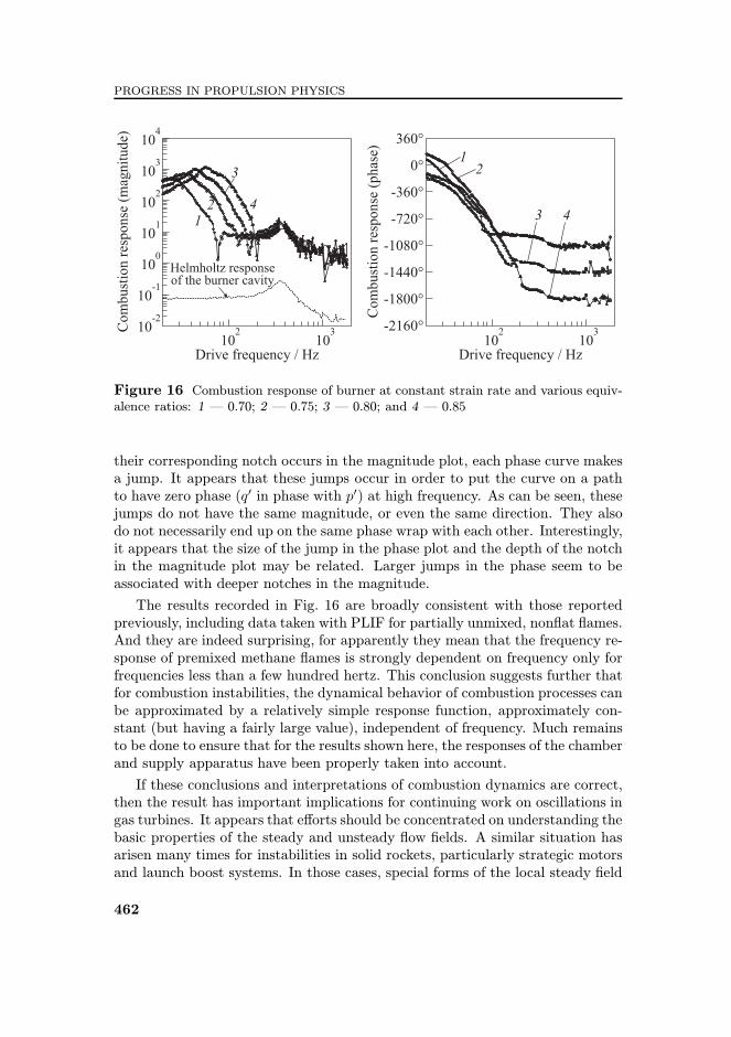
Experiments were performed on the burner with the blu¨ body positioned21 mm above the nozzle exit. The burner was operated on premixed methane(99.995% pure) and dry air. The sound pressure level of the acoustic ¦eld atthe §ame location was approximately 110.7 dB. In the data presented here, fourconditions were run with equivalence ratios of 0.70, 0.75, 0.80, and 0.85. Forthese four conditions, the total mass §ow rate was adjusted to hold the §amestrain rate roughly constant. In each case, the blu¨-body was allowed to come tothermal equilibrium prior to starting the experiment. Results of the experimentsare shown in Fig. 16. The combustion response function is the same as thatde¦ned above.
As can be seen, the peaks in the magnitude plots all occur between 20 and60 Hz. The peak in the response increases and shifts to the right (toward higherfrequency) as the equivalence ratio is increased. After their peaks, each curverolls o¨ to a combustion response magnitude around 10. At this point, thecurves exhibit notch behavior and then level o¨ at a combustion response levelof approximately 8. Similar to the response peaks, the frequencies at which thenotches occur increase with equivalence ratio.
The curves essentially coalesce and then make transitions through the broadpeaks between 200 and 500 Hz. This behavior is due to the Helmholtz resonanceassociated with the burner cavity. The dashed curve in the bottom of the mag-nitude plot shows the §uctuating pressure measured inside the burner cavity atthe base of the nozzle.
The phase plots show similar behavior for all the curves at low frequencies,.although it is unclear which zero phase point (i.e., −360◦, 0◦, or +360◦) eachcurve is approaching as the frequency tends to zero. For low frequencies, eachcurve appears to be rolling o¨ like a time delay. However, at the point where
461
PROGRESS IN PROPULSION PHYSICS
Figure 16 Combustion response of burner at constant strain rate and various equiv-alence ratios: 1 ¡ 0.70; 2 ¡ 0.75; 3 ¡ 0.80; and 4 ¡ 0.85
their corresponding notch occurs in the magnitude plot, each phase curve makesa jump. It appears that these jumps occur in order to put the curve on a pathto have zero phase (q′ in phase with p′) at high frequency. As can be seen, thesejumps do not have the same magnitude, or even the same direction. They alsodo not necessarily end up on the same phase wrap with each other. Interestingly,it appears that the size of the jump in the phase plot and the depth of the notchin the magnitude plot may be related. Larger jumps in the phase seem to beassociated with deeper notches in the magnitude.
The results recorded in Fig. 16 are broadly consistent with those reportedpreviously, including data taken with PLIF for partially unmixed, non§at §ames.And they are indeed surprising, for apparently they mean that the frequency re-sponse of premixed methane §ames is strongly dependent on frequency only forfrequencies less than a few hundred hertz. This conclusion suggests further thatfor combustion instabilities, the dynamical behavior of combustion processes canbe approximated by a relatively simple response function, approximately con-stant (but having a fairly large value), independent of frequency. Much remainsto be done to ensure that for the results shown here, the responses of the chamberand supply apparatus have been properly taken into account.
If these conclusions and interpretations of combustion dynamics are correct,then the result has important implications for continuing work on oscillations ingas turbines. It appears that e¨orts should be concentrated on understanding thebasic properties of the steady and unsteady §ow ¦elds. A similar situation hasarisen many times for instabilities in solid rockets, particularly strategic motorsand launch boost systems. In those cases, special forms of the local steady ¦eld
462

AIR-BREATHING, TURBOMACHINERY, AND LAPCAT
have been found to have dominant in§uences on the unsteady ¦elds. Processestransferring energy from the steady three-dimensional velocity ¦elds to acoustic¦elds often cause troublesome instabilities. Several important examples havebeen discussed by Culick [5]. The most recent work has been done in connectionwith the Ariane 5 booster motors; the case for gas turbine combustors is mostclearly made by the Siemens experience summarized above.
The obvious importance of unsteady combustion processes and their couplingto acoustical motion must not be forgotten! They are particularly evident inthe many studies of instabilities under lean conditions, notably those directedto de¦ning LBO limits. Probably, GE has had the most extensive continuousresearch program (see [38] for a good introduction) of any organization. However,as seems almost always to be the case, and is appropriate in an industrial setting,emphasis has been placed on trying to treat today£s problems today.
6 CONCLUDING REMARKS
When Bollay proposed active control of combustion dynamics in 1951, he had inmind an application quite di¨erent from those which have driven research in the¦eld during the past twenty years. His motivation, oscillations in liquid rockets,in fact became an increasingly severe problem. It has been ¤solved¥ for practicalpurposes by a combination of results and experience gained from large numbersof tests; and reasoning guided, sometimes imperfectly, by incomplete theory.
Combustion instabilities in thrust augmentors have been a continuing prob-lem. They have typically restricted portions of the operating envelope. Likelydue to a suggestion by Prof. Ffowes-Williams, Rolls Royce, Ltd. funded a researchprogram at Cambridge in augmentor instabilities that included the ¦rst success-ful experiments with active control. In the initial tests, loudspeakers were usedas actuators, but in the early 1990s, the Cambridge group ¦rst demonstrated, ina simple channel, control of oscillations by modulation of the fuel supply. It wasa single-input�single-output system. A modest amount of analysis accompaniedthe demonstrations, analysis which aided ex post facto interpretations, but wasin no sense predictive.
That Cambridge work, followed shortly by a program also involving ‚EcoleCentrale, Paris, collaborating with groups in Munich and Lyons, in many waysde¦ned the broad outlines of many works in the early to mid-1990s. Research inthe ¦eld was pursued vigorously, and several dissertations prepared at TechnischeUniversit�at, M�unchen produced, signi¦cantly, a new magnetostrictive actuator.That was an important item incorporated in a MIMO system installed in 270-megawatt Siemens power generators to combat a combustion instability. It is theonly case of full-scale operating systems with active control of combustors. Withinstallations in fourteen machines, approximately 140,000 hours of operation
463

PROGRESS IN PROPULSION PHYSICS
were accumulated. Continued studies clari¦ed the mechanism of the instability;relatively simple mechanical modi¦cations (¢passive control£) then allowed theactive control system to be discarded.Because of inevitable problems of instabilities accompanying development of
LP and LPP combustors for gas turbines, research has continued to the presenttime, although presently with subdued general enthusiasm. Re¦nements of fa-miliar sorts of equipment have produced much interesting data using for the mostpart well-established methods. Most of the observed behavior is poorly under-stood. In fact, virtually all the experimental results have not been satisfactorilyexplained. There is not one case involving active control of a combustion in-stability for which the unstable motion has been predicted and the subsequente¨ect of control predicted as well. On the one hand, it is easily understood whysuch a situation exists ¡ the problems are indeed di©cult. But it is not easilyunderstood why so little e¨ort seems to have been exerted in trying to correctsuch an obvious de¦ciency. As experience in the ¦eld of solid rocketry has shown,much can be learned, especially from approximate analyses of instabilities. Suchtheoretical results often suggest informative small-scale experiments.Unfortunately, it seems that much of the research done in this ¦eld, espe-
cially in the U.S., has been very applied. That is, experimental work has oftenbeen directed to solving problems which have been identi¦ed by manufactur-ers as begging solution in the very near future. Government funded programshave unfortunately often responsively been formulated to satisfy the same needs.That characteristic has been commonly shared irrespective of national borders.As a result, it is believed, when practical problems are found, there are fewgeneral principles to fall back upon, and a sad absence of well-established guide-lines. Advances in theoretical and experimental methods have not received thecontinuing support they merit.The great di©culty of discovering the true mechanisms of combustion in-
stabilities is perhaps the greatest obstacle to eliminating them. Probably, thesituation is fairly well-in-hand for LP and LPP systems; operational limits canbe set by extensive testing. The lengthy development program documented forthirty years by GE gives evidence of considerable success and represents essential-ly the ¤state-of-the-art.¥ There are some people who believe that the limits ofthose types of combustors may have been reached. That is, emissions (CO andoxides of nitrogen) cannot be reduced further. That belief is well-founded, beingbased on test and operational results.Whether the comparable state has been reached for RQL, or the unproven
trapped vortex idea, cannot be stated. (There is no Second Law of pollutantemissions.) Simply not enough is known about the systems to state limits withcon¦dence. That reasoning is partly behind justi¦cation of the experimentalwork touched upon in the last section. It is fairly clear that nonintrusive meth-ods o¨er the only promising basis for obtaining good spatial resolution of time-dependent behavior for combusting systems.
464

AIR-BREATHING, TURBOMACHINERY, AND LAPCAT
Several laser-based techniques are available, but it appears that some formof PLIF alone presently o¨ers the possibilities sought. Chemiluminescence hasproven very useful in several applications, but its simplicity is paid for withsevere reductions in spatial and temporal resolution, as well as with a loss ofinformation about the details of local chemistry. In some con¦gurations, onlyglobal characteristics are available.
There are many other promising possibilities for research programs, not cov-ered here. Theoretical, numerical (CFD plus combustion), and experimentalmethods all are far from the ends of their development. Moreover, the con-ceivable stakes are very high indeed. What is required, as usual, is resolve andintelligent planning.
As always is the case, investments in research, only a portion leading to prac-tical realizations, will be repaid handsomely; con¦dent and informed leadershipis essential.
ACKNOWLEDGMENTS
Preparation of this paper and the equipment required for the experiments re-ported in Section 5 were ¦nancially supported by the authors. The early Cal-tech work was supported by the Air Force O©ce of Scienti¦c Research, 1998�2003, the period when the ¦rst versions of the equipment shown in Fig. 15were constructed. The authors are indebted to several people, particularly Dr.G. Sturgess, for useful discussion of the material covered in the last part ofSection 4.
REFERENCES
1. Bollay, W. 1951. Aerodynamic stability and automatic control. J. Aero Sci.18(9):569�640.
2. Tsien, H. S. 1952. Servo-stabilization of combustion in rocket motors. ARS J.22:256�63.
3. Hermann, J., A. Orthmann, and S. Ho¨man. 1999. Application of active instabilitycontrol to a heavy duty gas turbine. XIV ISABE. Paper A99-34186.
4. Berenbrink, P., and S. Ho¨mann. 2000. Suppression of dynamic combustion insta-bilities by passive and active means. ASMETurbo Expo 2000. Paper 2000-GT-0079.
5. Culick, F. E.C. 2006. Unsteady motions in combustion chambers for propulsionsystems. AGARDograph RTO-AG-AVT-039.
6. Dines, P. J. 1983. Active control of §ame noise. Ph.D. Thesis. University of Cam-bridge.
465

PROGRESS IN PROPULSION PHYSICS
7. Heckl, M.A. 1986. Active control of the noise from a Rijke tube. IUTAM Sympo-sium on Aero and Hydro-Acoustics Proceedings. Springer-Verlag. 211�16.
8. Heckl, M.A. 1988. Active control of the noise from a Rijke tube. J. Sound Vib.124(1):117�33.
9. Ffowcs-Williams, J. E., P. J. Dines, and M.A. Heckl. 1985. Combustion system fora gas turbine. U.S. Patent 4,557,106.
10. Langhorne, P. J. 1988. Reheat buzz: An acoustically coupled combustion instability.Part 1. Experiment. J. Fluid Mech. 193:417�43.
11. Bloxsidge, G. J., A.P. Dowling, N. Hooper, and P. J. Langhorne. 1987. Active con-trol of an acoustically driven combustion instability. J. Theor. Appl. Mech. Sup-plement to Vol. 6. 161�75.
12. Moran, A. J., D. Steele, and A.P. Dowling. 2000. Active control of combustion andits applications. RTO AVT Symposium on Active Control Technology for EnhancedPerformance Operational Capabilities of Military Aircraft, Land Vehicles and SeaVehicles. Braunchweig, Germany.
13. Lang, W., T. Poinsot, and S.M. Candel. 1987. Active control of combustion insta-bility. Combust. Flame 70(3):281�89.
14. Poinsot, T., D. Veynante, F. Bourienne, S.M. Candel, E. Esposito, and J. Surget.1988. Initiation and suppression of combustion instabilities by active control. 22ndSymposium (International) on Combustion. The Combustion Institute. 1363�70.
15. Poinsot, T., F. Bourienne, S.M. Candel, E. Esposito, and W. Lang. 1989. Suppres-sion of combustion instabilities by active control. J. Propul. Power 5(1):14�20.
16. Fung, Y.T., V. Yang, and A. Sinha. 1991. Active control of combustion instabilitieswith distributed actuators. Combust. Sci. Technol. 78(6):217�45.
17. Fung, Y.T., and V. Yang. 1992. Active control of nonlinear pressure oscillations incombustion chambers. J. Propul. Power 8(4�6):1282�89.
18. Gulati, A., and E.C. Bigelow. 1990. Control of combustion instabilities. U.K.Patent Application, GB 2,239,961 A, Application No. 9027565.2.
19. Hantschk, C., J. Hermann, and D. Vortmeyer. 1996. Active instability control withdirect-drive servo valves in liquid-fueled combustion systems. 26th Symposium (In-ternational) on Combustion. The Combustion Institute. 2835�41.
20. Hermann, J., S. Gleis, and D. Vortmeyer. 1996. Active instability control (AIC)of spray combustors by modulation of liquid §ow rate. Combust. Sci. Technol.118(1):1�25.
21. Hermann, J., A. Orthmann, S. Ho¨mann, and P. Berenbrink. 2000. Combination ofactive instability control and passive measures to prevent combustion instabilitiesin a 260 MW heavy duty gas turbine. RTO AVO Symposium on Active ControlTechnology for Enhanced Performance Operational Capabilities of Military Air-craft, Land Vehicles and Sea Vehicles. Braunschweig, Germany.
22. Schadow, K.C., V. Yang, F. E.C. Culick, T. J. Rosfjord, G. Sturgess, andB. T. Zinn. 1997. Active combustion control for propulsion systems. AGARD Re-port 820.
23. Zel£dovich, Ya.B., G. I. Barenblatt, V.B. Librovich, and G.M. Mikhviladze. 1985.The mathematical theory of combustion and explosions. Translated from the Rus-sian by D.H. McNeill. N.Y.: Consultants Bureau (Plenum Press).
466

AIR-BREATHING, TURBOMACHINERY, AND LAPCAT
24. Lieuwen, T., and V. Yang. 2005. Combustion instabilities in gas turbine engines.AIAA progress in astronautics and aeronautics ser.
25. Neumeier, Y., and B. T. Zinn. 1996. Experimental demonstration of active con-trol of combustion instabilities using real time modes observation and secondaryfuel injection. 26th Symposium (International) on Combustion. The CombustionInstitute 2:2811�18.
26. Zinn, B. T. 2005. Smart combustors ¡ just around the corner. ASME Turbo Expo2005. Paper GT2005-69138.
27. Neumeier, Y., and B. T. Zinn. 1998. Methods, apparatus and systems for real timeidenti¦cation and control of modes of oscillation. U.S. Patent No. 5,719,791.
28. Johnson, C. E. 2006. Adaption control of combustion instabilities using real-timemodes observation. Ph.D. Dissertation. Mechanical Engineering, Georgia Instituteof Technology.
29. ’Astrom, K. J., and B. Wittenmark. 1995. Adaptive control. Reading, MA: Addison-Wesley Publishing Co.
30. Billoud, G., M.A. Galland, C. Huynh Huu, and S. E. Cancel. 1992. Adaptive activecontrol of combustion instabilities. Combust. Sci. Technol. 81(4):257�83.
31. Evesque, S. 2000. Adaptive control of combustion instabilities. Ph.D. Dissertation.University of Cambridge.
32. Evesque, S., and A.P. Dowling. 2001. LMS algorithms for adaptive control of com-bustion oscillations. Combust. Sci. Technol. 164(1):65�93.
33. Evesque, S., A. P. Dowling, and A. Annaswamy. 2003. Self-tuning regulators forcombustion oscillations. Proc. R. Soc. London, Ser. A 459(2035):1709�49.
34. Lieuwen, T., H. Torres, C. Johnson, and B. T. Zinn. 2001. A mechanism of com-bustion instability in lean premixed gas turbine combustors. J. Eng. Gas TurbinePower 123:182�89.
35. Roberts, R., A. Fiorentino, and W. Greene. 1977. Experimental clean combustionprogram. Part III: Final report. NASA CR-135253.
36. Gleason, L. C., and D.W. Bahr. 1979. Experimental clean combustion program.Part III: Final Report. NASA CR-135384.
37. Sabnis, J. 2005. Emissions and noise: The next frontier for airfcraf engine technolo-gies. AIAA/AAAF Aircraft Noise and Emission Reduction Symposium. Monterey,CA.
38. Mongia, H., T. J. Held, G.C. Hsia, and R.P. Panaandalai. 2005. Incorporationof combustion instability issues into design process: GE aeroderivative and aeroengines experience. In: [24]. Ch. 3.
39. Hoke, J. B., I. Segalman, K. S. Suskind, and R.D.C. Smith. 2001. Low NOX com-bustor for gas turbine engine. U.S. Patent No. 6,240,731 B1.
40. Hura, H. S., and H.C. Mongia. 1998. Prediction of NO emission from a lean domegas turbine combustor. AIAA Paper No. 98-3375.
41. Haynes, J., J. Janssen, C. Russell, and M. Ho¨man. 2006. Advanced combustionsystems for next generation gas turbines. GE Global Research. Report DE-FC26-OINT41020.
467

PROGRESS IN PROPULSION PHYSICS
42. Pun, W., S. Palm, and F.E.C. Culick. 2000. PLIF measurements of combustiondynamics in a burner under forced oscillatory conditions. AIAA Paper No. 2000-3123.
43. Pun, W. 2001. Measurement of thermo-acoustic coupling. Ph.D. Thesis. CaliforniaInstitute of Technology.
44. Kang, D.M. 2006. Measurements of combustion dynamics with laser-based diag-nostic techniques. Ph.D. Thesis. California Institute of Technology.
468