activated sludge off-gas carbon adsorption...
TRANSCRIPT

Activated Sludge Off-Gas Carbon Adsorption Treatment
Chester M. Morton, PE, BCEE
Malcolm Pirnie-Arcadis
Nat J. Federici, PE
NYCDEP Accountable Manager, Engineering Design & Construction
ABSTRACT
The Newtown Creek Wastewater Treatment Plant is New York City’s largest plant. It is being
upgraded to provide a dry weather treatment capacity of 1.17 cubic meters per day (m3/d) [310
million gallons per day (mgd)]. The plant is located within a densely populated area and odor
control will be provided on all its unit processes. The design parameters and performance data
are presented for one of its five odor control systems. It employs dual bed activated carbon
adsorbers, has a capacity to treat 105 cubic meters per second (m3/s) [220,000 cubic feet per
minute (cfm)] and was started up in December 2006. The system treats the emissions from grit
tanks, activated sludge tanks, final settling tanks and other emission sources. Approximately
80% of the air being treated is from the activated sludge tanks. The carbon of four of its thirteen
vessels, which received a higher hydrogen sulfide loading, was replaced after approximately four
years. The remaining vessels are operating with their original carbon exceeding the expected
carbon service life.
KEY WORDS
Activated sludge, activated carbon, carbon adsorption, hydrogen sulfide, odor
INTRODUCTION
The Newtown Creek Wastewater Treatment Plant is operated by the New York City Department
of Environmental Protection (DEP) and is the largest of New York City’s plants. The upgrade of
the plant to a dry weather capacity of 1.17 cubic meters per day (m3/d) [310 million gallons per
day (mgd)] and a wet weather flow of 2.64 m3/d (700 mgd) is nearing completion. It is located
in the north section of Brooklyn, near the Queens border. The plant receives approximately 0.64
m3/d (170 mgd) from Manhattan and 0.53 m
3/d (140 mgd) from Brooklyn and Queens. It
discharges to the East River.
The plant has no buffer zone. It is located in a neighborhood that is comprised of residential,
commercial and light industrial uses. A residential area is located one block west of the plant.
Approximately 30.5 meters (100 feet) from the plant’s final sedimentation tanks is a public
street. A nature walk is to be built around the plant’s perimeter, and a visitor center will be
located within the plant’s boundary. The New York City and State air emission limits and
proximity of the community resulted in the need for a highly effective odor control system.
Figure 1 is an aerial photograph of the site and surrounding community taken in 2004.
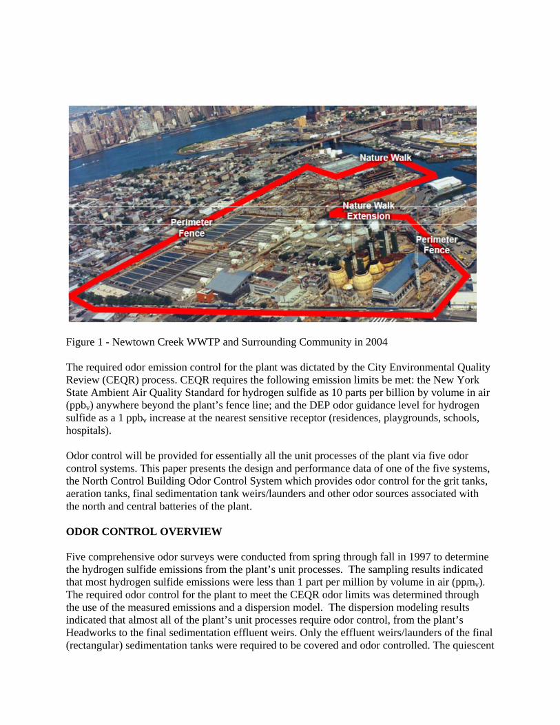
Figure 1 - Newtown Creek WWTP and Surrounding Community in 2004 The required odor emission control for the plant was dictated by the City Environmental Quality Review (CEQR) process. CEQR requires the following emission limits be met: the New York State Ambient Air Quality Standard for hydrogen sulfide as 10 parts per billion by volume in air (ppbv) anywhere beyond the plant’s fence line; and the DEP odor guidance level for hydrogen sulfide as a 1 ppbv increase at the nearest sensitive receptor (residences, playgrounds, schools, hospitals). Odor control will be provided for essentially all the unit processes of the plant via five odor control systems. This paper presents the design and performance data of one of the five systems, the North Control Building Odor Control System which provides odor control for the grit tanks, aeration tanks, final sedimentation tank weirs/launders and other odor sources associated with the north and central batteries of the plant. ODOR CONTROL OVERVIEW Five comprehensive odor surveys were conducted from spring through fall in 1997 to determine the hydrogen sulfide emissions from the plant’s unit processes. The sampling results indicated that most hydrogen sulfide emissions were less than 1 part per million by volume in air (ppmv). The required odor control for the plant to meet the CEQR odor limits was determined through the use of the measured emissions and a dispersion model. The dispersion modeling results indicated that almost all of the plant’s unit processes require odor control, from the plant’s Headworks to the final sedimentation effluent weirs. Only the effluent weirs/launders of the final (rectangular) sedimentation tanks were required to be covered and odor controlled. The quiescent
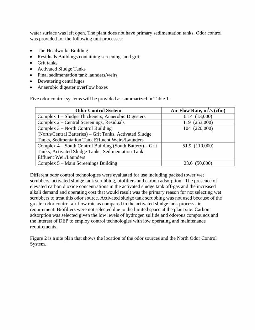
water surface was left open. The plant does not have primary sedimentation tanks. Odor control was provided for the following unit processes: The Headworks Building Residuals Buildings containing screenings and grit Grit tanks Activated Sludge Tanks Final sedimentation tank launders/weirs Dewatering centrifuges Anaerobic digester overflow boxes Five odor control systems will be provided as summarized in Table 1.
Odor Control System Air Flow Rate, m3/s (cfm) Complex 1 – Sludge Thickeners, Anaerobic Digesters 6.14 (13,000) Complex 2 – Central Screenings, Residuals 119 (253,000) Complex 3 – North Control Building (North/Central Batteries) – Grit Tanks, Activated Sludge Tanks, Sedimentation Tank Effluent Weirs/Launders
104 (220,000)
Complex 4 – South Control Building (South Battery) – Grit Tanks, Activated Sludge Tanks, Sedimentation Tank Effluent Weir/Launders
51.9 (110,000)
Complex 5 – Main Screenings Building 23.6 (50,000) Different odor control technologies were evaluated for use including packed tower wet scrubbers, activated sludge tank scrubbing, biofilters and carbon adsorption. The presence of elevated carbon dioxide concentrations in the activated sludge tank off-gas and the increased alkali demand and operating cost that would result was the primary reason for not selecting wet scrubbers to treat this odor source. Activated sludge tank scrubbing was not used because of the greater odor control air flow rate as compared to the activated sludge tank process air requirement. Biofilters were not selected due to the limited space at the plant site. Carbon adsorption was selected given the low levels of hydrogen sulfide and odorous compounds and the interest of DEP to employ control technologies with low operating and maintenance requirements. Figure 2 is a site plan that shows the location of the odor sources and the North Odor Control System.

Figure 2 - Newtown Creek WWTP Site Plan

ACTIVATED CARBON AND CARBON ADSORPTION SYSTEMS Activated carbon has been used for centuries purifying water and air. It received focused attention in World War I when it was used in gas masks to remove poisonous gases, which spurred its further development/use in industrial and environmental applications.1 Its porous structure and high surface area provides its unique adsorptive properties. It is hydrophobic and therefore tends to attract more non-polar than polar compounds. Carbon can be provided as granular (unshaped), or shaped such as a pellet. The advantage of pelletized carbon is that it has a higher porosity, density, hardness and lower headloss characteristics. Activated carbon is manufactured from a number of raw materials including coal (anthracite, bituminous, lignite), coconut shells, peat, and wood. Activated carbon for wastewater treatment odor control applications is typically manufactured from coal and coconut shells. The manufacturing process includes the following steps. Crushing and sieving. The raw carbon material is processed to the desired particle size
distribution Thermal activation. Thermal activation consists of two steps. The first step is carbonization
which is conducted at high temperatures and causes compounds within the raw material to volatilize resulting in a carbon rich material (char). Activation is the second step in which the remaining raw material is activated using an oxidizing agent, typically steam, in a direct fired furnace. This process enhances the pore structure which is the key to the adsorptive capacity of activated carbon.
Alternatively to the thermal activation process, the raw material can be carbonized and conditioned with a chemical such as an alkali, phosphoric acid or zinc chloride.
Carbon can be provided in a granular or pelletized form. The granular form has been crushed and screened, and has an irregular shape with a mean particle size of 1 to 5 millimeters. Pelletized carbon is often produced in the shape of a cylinder. In the production process, after carbonization the carbon is pulverized, mixed with binders and then extruded. The shaped carbon is then activated which imparts high internal porosity. Pelletized carbon has a higher density and hardness, and lower headloss than granular carbon. Carbon can be regenerated after its capacity is expended. A disadvantage to regeneration is that its cost can be close to the cost of purchasing new carbon and the adsorptive capacity of the carbon is less than the original carbon. After a number of regenerations the reduced capacity and cost makes further regenerations uneconomical. Regeneration is conducted thermally in a rotary kiln, multiple hearth or fluidized bed at 600 to 1,000 degrees C. Attrition losses of up to 5% occur.

Carbon can also be regenerated through the use of steam. Steam regeneration is conducted at lower temperatures, is used for compounds with low boiling points and is usually conducted onsite. The steam is passed through the vessel in the opposite direction of the process stream. The steam is condensed in a heat exchanger and the adsorbate is recovered for reuse. Hot nitrogen gas can be used instead of steam. Parameters that are used in the selection of carbon in wastewater treatment odor control applications include: Hydrogen sulfide adsorption capacity. This is expressed as mass adsorbed per unit volume,
milligram per cubic centimeter (mg/cc). Values range from 0.02 (Calgon BPL 4 X 6 mesh virgin carbon to 0.30 (Siemens Midas, 4 mm pelletized, manufactured by a proprietary process to provide greater adsorption capacity) (ASTM D 6646).
Butane Activity Number. This parameter is an indicator of a carbon’s capacity to adsorb
organic compounds. It is a measure of the mass of butane adsorbed per unit weight of carbon expressed as a percentage. The Butane Activity No. has replaced the Carbon Tetrachloride (CCl4) No. because of the adverse affect of carbon tetrachloride on the ozone layer. The relationship between CCl4 and Butane is: CCl4 No. = 2.52 X Butane No. Typical values are 23.3% (Calgon BPL 4 X 6 mesh virgin carbon) to 27.5% (Siemens VoCarb P70). (ASTM D5742 – 95, reapproved 2010)
Ball-Pan Hardness. Hardness is the resistance of a granular carbon to be broken down to
smaller particles after being shaken with steel balls. Typical values range from 95 to 97. (ASTM D 3802)
Headloss. Carbon manufacturers typically represent the headloss of their carbon graphically
with pressure drop [inches water column (WC)] plotted on the y-axis versus superficial velocity (feet/minute) on the x-axis. Examples of headloss are: Calgon’s granular BPL 4 X 6 carbon with a headloss of 1.8 inches WC at 50 feet/minute; and Siemens pelletized VoCarb P70 carbon of 0.5 inches WC at 50 feet/minute. This comparison points up the lower headloss of a pelletized carbon. While the lower headloss of the pelletized carbon indicates lower power requirements for a system using this carbon, the capital cost for the carbon should be considered.
Carbon is configured in carbon adsorbers in beds typically 0.91 meter (3 feet) deep. As air passes through the carbon, hydrogen sulfide and other volatile organic compounds (VOCs) are adsorbed to the carbon in a relatively shallow depth referred to as a mass transfer zone (MTZ). As the carbon becomes loaded with these compounds, the MTZ progresses through the bed in the direction of the air flow, and is referred to as a wave-front. There is a concentration gradient of compounds in the carbon bed, with a higher concentration in the upstream portion of the bed and a lower concentration downstream of the MTZ. When the wave-front reaches the end of the bed, breakthrough occurs, i.e., the hydrogen sulfide and VOCs begins to appear in the air being exhausted from the vessel.
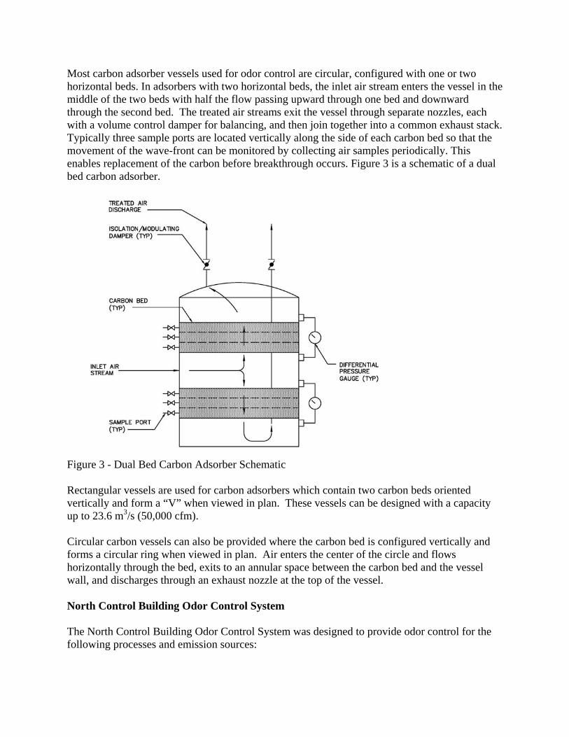
Most carbon adsorber vessels used for odor control are circular, configured with one or two horizontal beds. In adsorbers with two horizontal beds, the inlet air stream enters the vessel in the middle of the two beds with half the flow passing upward through one bed and downward through the second bed. The treated air streams exit the vessel through separate nozzles, each with a volume control damper for balancing, and then join together into a common exhaust stack. Typically three sample ports are located vertically along the side of each carbon bed so that the movement of the wave-front can be monitored by collecting air samples periodically. This enables replacement of the carbon before breakthrough occurs. Figure 3 is a schematic of a dual bed carbon adsorber.
Figure 3 - Dual Bed Carbon Adsorber Schematic Rectangular vessels are used for carbon adsorbers which contain two carbon beds oriented vertically and form a “V” when viewed in plan. These vessels can be designed with a capacity up to 23.6 m3/s (50,000 cfm). Circular carbon vessels can also be provided where the carbon bed is configured vertically and forms a circular ring when viewed in plan. Air enters the center of the circle and flows horizontally through the bed, exits to an annular space between the carbon bed and the vessel wall, and discharges through an exhaust nozzle at the top of the vessel. North Control Building Odor Control System The North Control Building Odor Control System was designed to provide odor control for the following processes and emission sources:

Grit Tanks Headspace Activated Sludge Tanks Sedimentation Tank Influent Channel Sedimentation Tank Effluent Weirs/Launders Return Activated Sludge (RAS)/Waste-Activated Sludge (WAS) Well & Scum Wet Well Due to the plant’s phased construction schedule, the south battery is not yet completed which will treat approximately one-third of the plant’s influent flow rate. Therefore the plant’s total influent flow rate is being treated in the North and Central Batteries. As a result of the greater Biochemical Oxygen Demand (BOD) loading to these batteries, the process air flow rate to the activated sludge tanks has been increased 9.4 m3/s (20,000 cfm), from 75.5 m3/d (160,000 cfm) to 85.0 m3/s (180,000 cfm). This greater activated sludge tank process air flow rate and providing odor control for the Interim Skimmings Building and Interim Grit Buildings has resulted in the temporary elimination of treatment of other odor sources. Figure 4 is a schematic of the North Control Building Odor Control System. The process and air sources that were originally intended for treatment and those currently being treated are summarized in Table 2. Figure 4 illustrates the entry of interim grit building and activated sludge tank exhaust air from the North and Central Battery activated sludge tanks, and from the covered sedimentation tanks into opposite ends of the inlet plenum. The inlet plenum feeds thirteen carbon adsorption treatment trains operating in parallel. Each treatment train consists of a grease filter/mist eliminator, fan and carbon adsorption vessel. The fan pulls air from the inlet plenum, through a grease filter-mist eliminator and then pushes it through its designated dual carbon bed vessel, into an exhaust plenum and out a 38.1 meter (125 ft.) high exhaust stack. The system went online in December 2006.
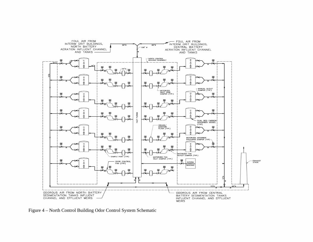
Figure 4 – North Control Building Odor Control System Schematic

Table 2 – North Control Building Odor Control System Design and Interim Air Flow Rates Process/Air Source Design Interim
m3/s (cfm) m3/s (cfm)
Grit Tank Headspace Ventilation 3.31 (7,000) 0 Aeration Tank Process Air 75.5 (160,000) 85.0 (180,000) Exhaust to Maintain Negative Pressure Under Covers 6.8 (14,400) 0 Aeration Tank Influent Channel Mixing Air 1.42 (3,000) 1.42 (3,000) Aeration Tank Channel Headspace Ventilation 1.89 (4,000) 0 RAS Splitter Box 0.19 (400) 0 Sedimentation Influent Channel Mixing Air 1.7 (3,600) 1.7 (3,600) Sedimentation Channel Headspace Ventilation 1.04 (2,200) 0 Effluent Weirs 9.44 (20,000) 9.73 (20,600) RAS/WAS Well & Scum Well 2.55 (5,400) 0 Interim Skimmings Building 0 1.42 (3000) Interim Grit Buildings 0 5.67 (12,000) Total 104 (220,000) 105 (222,200)
Each vessel has three carbon sample ports aligned vertically along the carbon beds which enable the progression of the wave front to be monitored. Figure 5 is a photo of one the system’s carbon adsorber vessels. Table 3 summarizes the design parameters for the carbon adsorbers including the specific carbon being used.
Figure 5 - North Control Building Carbon Adsorber
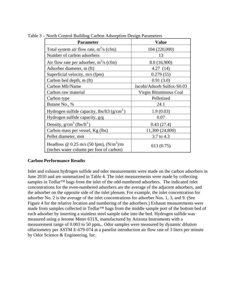
Table 3 – North Control Building Carbon Adsorption Design Parameters
Parameter Value
Total system air flow rate, m3/s (cfm) 104 (220,000) Number of carbon adsorbers 13
Air flow rate per adsorber, m3/s (cfm) 8.0 (16,900) Adsorber diameter, m (ft) 4.27 (14) Superficial velocity, m/s (fpm) 0.279 (55) Carbon bed depth, m (ft) 0.91 (3.0) Carbon Mfr/Name Jacobi/Adsorb Sulfox-S0.03 Carbon raw material Virgin Bituminous Coal Carbon type Pelletized Butane No., % 24.1
Hydrogen sulfide capacity, lbs/ft3 (g/cm3 ) 1.9 (0.03) Hydrogen sulfide capacity, g/g 0.07
Density, g/cm3 (lbs/ft3 ) 0.43 (27.4) Carbon mass per vessel, Kg (lbs) 11,300 (24,800) Pellet diameter, mm 3.7 to 4.3
Headloss @ 0.25 m/s (50 fpm), (N/m2)/m (inches water column per foot of carbon)
613 (0.75)
Carbon Performance Results Inlet and exhaust hydrogen sulfide and odor measurements were made on the carbon adsorbers in June 2010 and are summarized in Table 4. The inlet measurements were made by collecting samples in Tedlar™ bags from the inlet of the odd-numbered adsorbers. The indicated inlet concentrations for the even-numbered adsorbers are the average of the adjacent adsorbers, and the adsorber on the opposite side of the inlet plenum. For example, the inlet concentration for adsorber No. 2 is the average of the inlet concentrations for adsorber Nos. 1, 3, and 9. (See Figure 4 for the relative location and numbering of the adsorbers.) Exhaust measurements were made from samples collected in Tedlar™ bags from the middle sample port of the bottom bed of each adsorber by inserting a stainless steel sample tube into the bed. Hydrogen sulfide was measured using a Jerome Meter 631X, manufactured by Arizona Instruments with a measurement range of 0.003 to 50 ppmv. Odor samples were measured by dynamic dilution olfactometry per ASTM E-679-074 at a panelist introduction air flow rate of 3 liters per minute by Odor Science & Engineering, Inc.
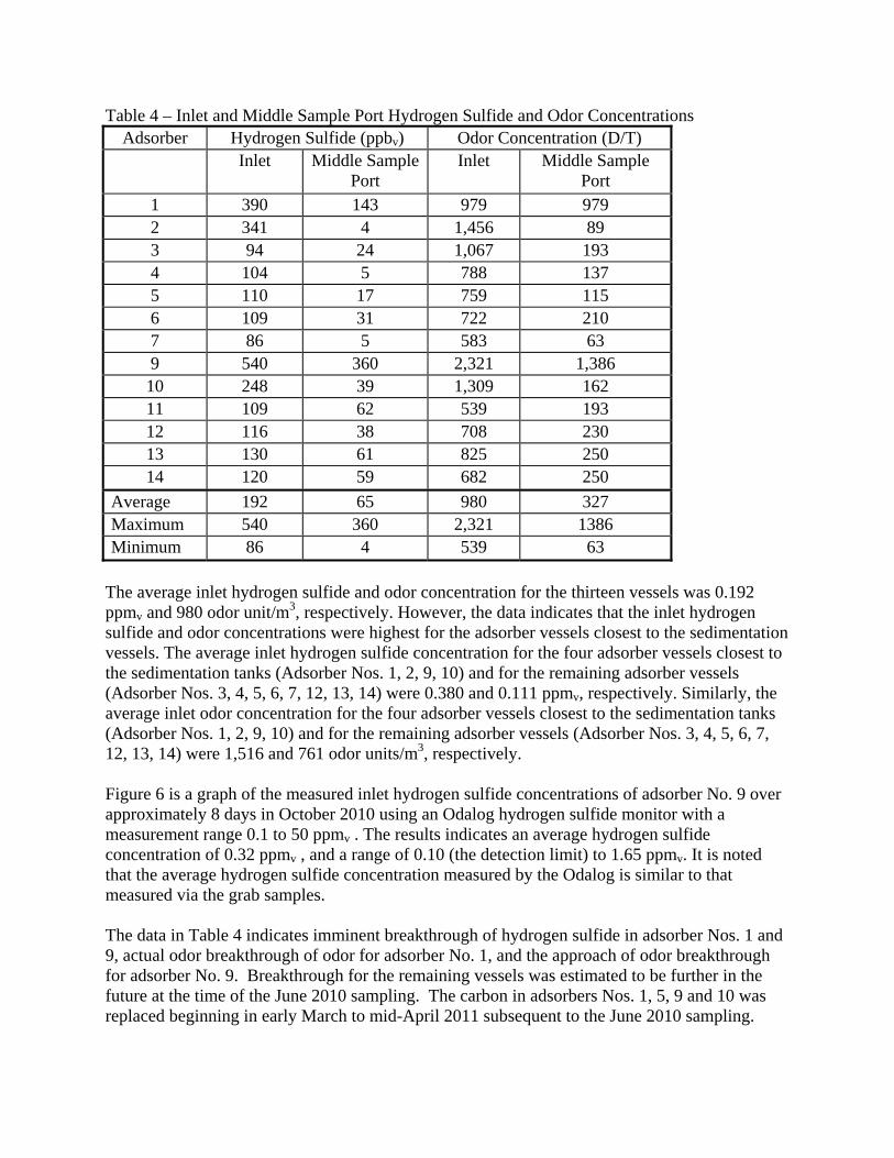
Table 4 – Inlet and Middle Sample Port Hydrogen Sulfide and Odor Concentrations Adsorber Hydrogen Sulfide (ppbv) Odor Concentration (D/T)
Inlet Middle Sample Port
Inlet Middle Sample Port
1 390 143 979 979 2 341 4 1,456 89 3 94 24 1,067 193 4 104 5 788 137 5 110 17 759 115 6 109 31 722 210 7 86 5 583 63 9 540 360 2,321 1,386 10 248 39 1,309 162 11 109 62 539 193 12 116 38 708 230 13 130 61 825 250 14 120 59 682 250
Average 192 65 980 327 Maximum 540 360 2,321 1386 Minimum 86 4 539 63
The average inlet hydrogen sulfide and odor concentration for the thirteen vessels was 0.192 ppmv and 980 odor unit/m3, respectively. However, the data indicates that the inlet hydrogen sulfide and odor concentrations were highest for the adsorber vessels closest to the sedimentation vessels. The average inlet hydrogen sulfide concentration for the four adsorber vessels closest to the sedimentation tanks (Adsorber Nos. 1, 2, 9, 10) and for the remaining adsorber vessels (Adsorber Nos. 3, 4, 5, 6, 7, 12, 13, 14) were 0.380 and 0.111 ppmv, respectively. Similarly, the average inlet odor concentration for the four adsorber vessels closest to the sedimentation tanks (Adsorber Nos. 1, 2, 9, 10) and for the remaining adsorber vessels (Adsorber Nos. 3, 4, 5, 6, 7, 12, 13, 14) were 1,516 and 761 odor units/m3, respectively. Figure 6 is a graph of the measured inlet hydrogen sulfide concentrations of adsorber No. 9 over approximately 8 days in October 2010 using an Odalog hydrogen sulfide monitor with a measurement range 0.1 to 50 ppmv . The results indicates an average hydrogen sulfide concentration of 0.32 ppmv , and a range of 0.10 (the detection limit) to 1.65 ppmv. It is noted that the average hydrogen sulfide concentration measured by the Odalog is similar to that measured via the grab samples. The data in Table 4 indicates imminent breakthrough of hydrogen sulfide in adsorber Nos. 1 and 9, actual odor breakthrough of odor for adsorber No. 1, and the approach of odor breakthrough for adsorber No. 9. Breakthrough for the remaining vessels was estimated to be further in the future at the time of the June 2010 sampling. The carbon in adsorbers Nos. 1, 5, 9 and 10 was replaced beginning in early March to mid-April 2011 subsequent to the June 2010 sampling.

The higher inlet hydrogen sulfide concentration for adsorber Nos. 1, 9, 5 and 10 is believed to be the result of elevated concentrations of hydrogen sulfide (and odor) from beneath the covers of the sedimentation tank launders/weirs. A maximum hydrogen sulfide concentration of up to 8 ppmv was measured there. It is believed these elevated hydrogen sulfide concentrations are due to the fall of wastewater from the weirs into the effluent launders and hydrogen sulfide volatilization that results from the fall. By comparison the hydrogen sulfide concentrations measured beneath the covers over the activated tanks ranged from 0.005 to 0.022 ppmv.

Figure 6 - Carbon Adsorber No. 9 Inlet Hydrogen Sulfide Concentrations

The thirteen carbon adsorption trains of the North/Central Battery Odor Control System went online in December 2006. From early March to mid-April 2011, the carbon in adsorbers Nos. 1, 5, 9 and 10 were replaced. This results in a carbon service life of approximately 4.33 years for these four adsorbers, with operation continuing for the remaining nine vessels with their original carbon. It is noted that adsorbers Nos. 1 and 9 are closest to the end of the inlet plenum that receives exhaust air being collected from the sedimentation tank launder/weirs. CONCLUSIONS The thirteen carbon adsorption trains of the North Control Building Odor Control System went online in December 2006. The hydrogen sulfide and odor exhaust from the units were monitored routinely for hydrogen sulfide and odor. The approach of breakthrough was determined in three of the carbon vessels in June 2010. From early March to mid-April 2011 the carbon in four of the thirteen vessels was replaced. This resulted in a carbon service life of approximately 4.33 yrs for these vessels. The carbon in the remaining nine vessels is still in service. Three of the four vessels in which the carbon was replaced were closest to the sedimentation tanks and were receiving the highest hydrogen sulfide loadings which are believed to have driven the need for the carbon replacement. The remaining vessels which receive the bulk of their inlet loading from the aeration tanks are still in service. Carbon with a higher hydrogen sulfide adsorption capacity and comparable Butane Activity should be considered for future use in the adsorbers closest to the aeration tanks. The 4+ years carbon operating life in the vessels where the carbon was replaced and in the vessels still using the original carbon indicates a successful technology and carbon media selection, system design and operation. REFERENCES 1 Menendez-Diaz, J.A., Martin-Gullon, J., Types of Carbon Adsorbents and their Production
in: Activated Carbon Surfaces in Environmental Remediation, edited by Theresa Bandosz, Elsevier, 2006, pages 1-47.