act-10-0043 precision deployable mast for the swot* …
TRANSCRIPT

National Aeronautics and Space Administration
ACT-10-0043 PRECISION DEPLOYABLE MAST FOR THE SWOT* KARIN INSTRUMENT:
PI: Dr. Greg Agnes Jet Propulsion Laboratory California Institute of Technology
October 29th, 2014
*Mission Concept – Pre-decisional – for Planning and Discussion Purposes Only

© 2014 California Institute of Technology. U.S. Government sponsorship acknowledged.
Team
• Greg Agnes – PI • Mark Thomson – Co-I • Lee Peterson – Co-I • Ernesto Rodriguez – Co-I • Richard Hughes – Collaborator, SWOT* MSE • Jeff Waldman – CogE / Analyst • Dan Kahn – Design / Test • Mickey Hui - Designer
2
*Mission Concept – Pre-decisional – for Planning and Discussion Purposes Only

© 2014 California Institute of Technology. U.S. Government sponsorship acknowledged.
SWOT* Mission Concept
Mission Architecture
Oceanography: Characterize the ocean mesoscale and sub-mesoscale circulation
at spatial resolutions of 15 km and greater.
Hydrology: To provide a global inventory of
all terrestrial water bodies whose surface
area exceeds (250m)2 (lakes, reservoirs, wetlands) and rivers whose width exceeds
100 m (requirement) (50 m goal) (rivers).
• To measure the global storage change in
fresh water bodies at sub-monthly, seasonal, and annual time scales.
• To estimate the global change in river discharge at sub-monthly, seasonal, and
annual time scales.
Mission Science
• Ka-band SAR interferometric (KaRIn) system with 2 swaths, 50 km each
• Produces heights and co-registered all-weather imagery
• Use conventional Jason-class altimeter for nadir coverage, radiometer for wet-tropospheric delay, and GPS/Doris/LRA for POD.
• On-board data compression over the ocean (1 km2 resolution). No land data compression onboard.
• Partnered mission with CNES & CSA • Science mission duration of 3 years
• 873 km Orbit, 78º Inclination, 22 day repeat
• Flight System: ~1700Kg, ~1900W
• Launch Vehicle: NASA Medium class
• Cat 2 Project, Risk Class: C (TBC) • Target Launch Readiness: Oct 2020
3 Pre-decisional – for Planning and Discussion Purposes Only

© 2014 California Institute of Technology. U.S. Government sponsorship acknowledged.
Task objectives
• Objective Reduce the SWOT* mission’s performance margin and cost risk by designing and prototyping a lightweight, precision-deployable mast for the SWOT* KaRIn antenna.
• Specifically, we : – Built a full-scale, deployable prototype of the SWOT* KaRIn Mast – Performed deployment testing on the prototype and access its repeatability. – Developed a lightweight pointing adjustment mechanism. – Initiated a nonlinear, multiphysics model of the deployment precision and post-
deployment thermal soak stability.
4
*Mission Concept – Pre-decisional – for Planning and Discussion Purposes Only

© 2014 California Institute of Technology. U.S. Government sponsorship acknowledged.
Mass Summary
90° Hinge
Inboard Boom
S/C Root and Location of Cable Spooler
180° Hinge
Outboard Boom
Reflector Array
5
Assembly Qty CBE Mass UNC
CBE+UNC As Meas. Mass Alloca6on
Mass (grams) % (grams) (grams) (grams)
SWOT* Boom Assy 1 19519 30% 25375 19685 41200 Hinge Assy 2 3529 30% 4588 3583 Cable 1 65 30% 85 65 Cable Spooler 1 0 30% 0 0 Inboard Boom 1 6930 30% 9009 6824 Outboard Boom 1 4654 30% 6050 4643 Center Pulley 1 140 30% 182 132 Outboard Boom Close Out 1 672 30% 874 700
*Mission Concept – Pre-decisional – for Planning and Discussion Purposes Only

© 2014 California Institute of Technology. U.S. Government sponsorship acknowledged.
Frequency
• Model assumes a reflector array mass of 24.0 kg. – This is the same for both the
model with the adjustment mechanism and without the adjustment mechanism
• The first mode of the system meets the 7Hz frequency requirement. – Requirement: The deployed
modal frequencies of a 2 mast antenna attached to the metering structure in a complete S/C configuration in a free-free environment shall be greater than 7Hz.
Mode 7: Z Axis Bend Mode
6
Mode Frequency (Hz)
No Array Adjustment Mech. With Array Adjustment Mech. CBE CBE+UNC Alloc. CBE CBE+UNC Alloc.
7 7.53 7.44 7.28 7.43 7.35 7.20 8 8.20 8.08 7.87 8.18 8.06 7.85 9 8.97 8.96 8.95 8.70 8.69 8.69
Mode 8: X Axis Bend Mode
Mode 9: Y Axis Torsion Mode
© 2014 California Institute of Technology. U.S. Government sponsorship acknowledged.
National Aeronautics and Space Administration
Hinge Testing

© 2014 California Institute of Technology. U.S. Government sponsorship acknowledged.
Hinge Testing Test Set-up
• Test set-up is similar for both the 90 degree root hinge and 180 degree mid-hinge.
• 4 cameras set up around the hinge to image targets affixed to the hinge bodies. – Each camera sees 2 targets, one on
the upper hinge body and one on the lower hinge body.
• Each camera uses NAMS (nano meter accurate measuring system) to measure the relative motion between the hinge bodies.
• These recorded motions are used to calculate the rigid body translation and rotation of the upper hinge body relative to the lower hinge body.
Targets

© 2014 California Institute of Technology. U.S. Government sponsorship acknowledged.
Results – Both Hinge Bodies have completed lab testing
9

© 2014 California Institute of Technology. U.S. Government sponsorship acknowledged.
Hinge Testing Test Results
• Grey circles show the average pointing error for each deployment. – Some excursions from the requirement are shown due to not using any lubricant on the balls.
Root Hinge 90 degrees No lubrication on balls
0 2 4 6 8 10 12 14 16
x 104
-10
-5
0
5
10Rigid Body Rotations, X
Time Step
Rota
tion
(arc
sec)
0 2 4 6 8 10 12 14 16
x 104
-10
-5
0
5
10Rigid Body Rotations, Y
Time Step
Rota
tion
(arc
sec)
0 2 4 6 8 10 12 14 16
x 104
-10
-5
0
5
10Rigid Body Rotations Z
Time Step
Rota
tion
(arc
sec)
dθdθavgReq
dθdθavgReq
dθdθavgReq
© 2014 California Institute of Technology. U.S. Government sponsorship acknowledged.
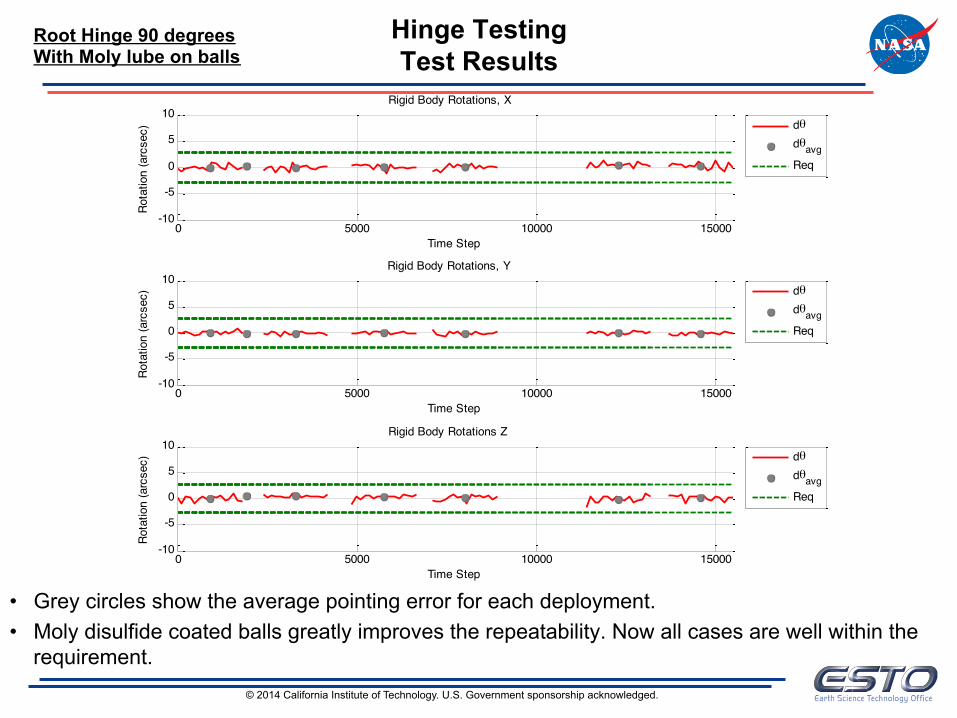
Hinge Testing Test Results
• Grey circles show the average pointing error for each deployment. • Moly disulfide coated balls greatly improves the repeatability. Now all cases are well within the
requirement.
Root Hinge 90 degrees With Moly lube on balls
0 5000 10000 15000-10
-5
0
5
10Rigid Body Rotations, X
Time Step
Rota
tion
(arc
sec)
0 5000 10000 15000-10
-5
0
5
10Rigid Body Rotations, Y
Time Step
Rota
tion
(arc
sec)
0 5000 10000 15000-10
-5
0
5
10Rigid Body Rotations Z
Time Step
Rota
tion
(arc
sec)
dθdθavgReq
dθdθavgReq
dθdθavgReq

© 2014 California Institute of Technology. U.S. Government sponsorship acknowledged.
Hinge Testing Test Results
• Grey circles show the average pointing error for each deployment. – Some excursions from the requirement are shown due to not using any lubricant on the balls.
Mid Hinge 180 degrees No lubricant on balls
0 2000 4000 6000 8000 10000 12000 14000 16000 18000-10
-5
0
5
10Rigid Body Rotations, X
Time Step
Rota
tion
(arc
sec)
0 2000 4000 6000 8000 10000 12000 14000 16000 18000-10
-5
0
5
10Rigid Body Rotations, Y
Time Step
Rota
tion
(arc
sec)
0 2000 4000 6000 8000 10000 12000 14000 16000 18000-10
-5
0
5
10Rigid Body Rotations Z
Time Step
Rota
tion
(arc
sec)
dθdθavgReq
dθdθavgReq
dθdθavgReq

© 2014 California Institute of Technology. U.S. Government sponsorship acknowledged.
Hinge Testing Test Results
• Grey circles show the average pointing error for each deployment. • Moly disulfide coated balls greatly improves the repeatability. Now all cases are well within the
requirement.
Mid Hinge 180 degree With Moly lube on balls
-2000 0 2000 4000 6000 8000 10000 12000-10
-5
0
5
10Rigid Body Rotations, X
Time Step
Rota
tion
(arc
sec)
-2000 0 2000 4000 6000 8000 10000 12000-10
-5
0
5
10Rigid Body Rotations, Y
Time Step
Rota
tion
(arc
sec)
-2000 0 2000 4000 6000 8000 10000 12000-10
-5
0
5
10Rigid Body Rotations Z
Time Step
Rota
tion
(arc
sec)
dθdθavgReq
dθdθavgReq
dθdθavgReq

© 2014 California Institute of Technology. U.S. Government sponsorship acknowledged.
Hinge Testing 90 degree rotation of set up
• The orientation of the hinge was rotated by 90 degrees to observe the effect (if any) that gravity has on the hinge deployment repeatability.
14
Hinge Standard Orientation
Hinge Rotated Orientation
Gravity Gravity

© 2014 California Institute of Technology. U.S. Government sponsorship acknowledged.
Hinge Testing Test Results
• Grey circles show the average pointing error for a deployment. • For this case, the hinge was rotated vertically to see if gravity had an affect on point repeatability. • All cases well within requirements. Gravity has no discernible impact on performance.
Mid Hinge 180 degree Rot90 With Moly lube on balls
0 2000 4000 6000 8000 10000 12000 14000 16000-10
-5
0
5
10Rigid Body Rotations, X
Time Step
Rota
tion
(arc
sec)
0 2000 4000 6000 8000 10000 12000 14000 16000-10
-5
0
5
10Rigid Body Rotations, Y
Time Step
Rota
tion
(arc
sec)
0 2000 4000 6000 8000 10000 12000 14000 16000-10
-5
0
5
10Rigid Body Rotations Z
Time Step
Rota
tion
(arc
sec)
dθdθavgReq
dθdθavgReq
dθdθavgReq

© 2014 California Institute of Technology. U.S. Government sponsorship acknowledged.
Hinge Testing Performance Summary
• Hand burnishing molybdenum disulfide onto the balls greatly improved repeatability by reducing friction as the balls slide into their cones.
• All cases using the moly lube met the hinge repeatability sub-allocation. • This was in agreement with the nonlinear modeling results presented
last summer. • Changing the direction of gravity in relation to the hinge had no impact
on the deployment repeatability.

© 2014 California Institute of Technology. U.S. Government sponsorship acknowledged.
National Aeronautics and Space Administration
Mast Kinematic Testing

© 2014 California Institute of Technology. U.S. Government sponsorship acknowledged.
Mast Testing Kinematic Testing
• The deployable mast is tested through its full range of motion while supported by its gravity offloading fixture in the high bay of building 299 to verify the kinematic working of the mechanism. – Mid-hinge moves through 180 degrees of motion. – Root hinge moves through 90 degrees of motion. – No performance data taken during this testing.
Fully Stowed Mid Hinge Deployment Mid Hinge Deployed Fully Deployed
© 2014 California Institute of Technology. U.S. Government sponsorship acknowledged.
National Aeronautics and Space Administration
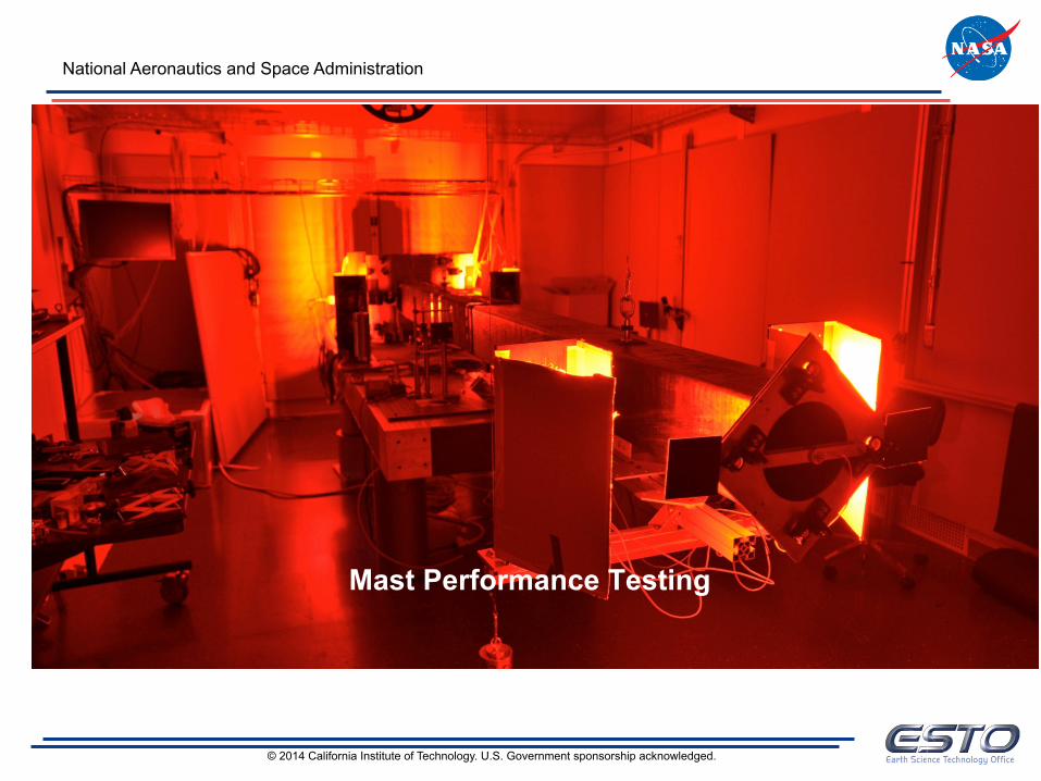
Mast Performance Testing

© 2014 California Institute of Technology. U.S. Government sponsorship acknowledged.
Mast Testing Performance Testing Setup
• These two pictures show the mast in its not deployed and deployed states.
• Not deployed picture shows the red lights used for the optical path. – Use of the telescope dimmed the image considerably.
These lights brighten it back to useable levels. • Deployed picture shows offload GSE attached to
ceiling (large wheels on tracks).
Mast Not Deployed Mast Deployed

© 2014 California Institute of Technology. U.S. Government sponsorship acknowledged.
Mast Testing Performance Testing Setup Invar Breadboard Closeup
• NAMS Optical Path used to measure twist (rotation in Y) of the mast tip.
• Laser Path used to measure tip/tilt (rotation in X and Z) of the mast tip.
NAMS Optical Path Components
Laser Path Components

© 2014 California Institute of Technology. U.S. Government sponsorship acknowledged.
Mast Testing Performance Testing Setup
Optical Paths
TeleWithHinge TeleNoHinge
Green Path: Half of field of view sees a target located at the mast tip. Blue Path: Pick off mirror bounces half of field of view to “fixed” target located on breadboard
Invar Breadboard

© 2014 California Institute of Technology. U.S. Government sponsorship acknowledged.
Mast Testing Performance Testing Setup - Laser Paths
4 paths with similar functions: Laser bounces from Invar breadboard to mast tip to camera located on Invar breadboard.
Invar Breadboard

© 2014 California Institute of Technology. U.S. Government sponsorship acknowledged.
Mast Testing Performance Testing Results - Laser Line
• Green dashed line is the requirement.
• Reasonable agreement between the autocollimator and the laser line results. – Both methods indicate that the
deployable mast is well within its requirements.
0 1 2 3 4 5 6 7 8
x 104
-8
-6
-4
-2
0
2
4
6
8
Time (secs)
Rota
tion
(arc
secs
)
Laser Line: Mast Rot X
Laser AvgAutocollimator
0 1 2 3 4 5 6 7 8
x 104
-8
-6
-4
-2
0
2
4
6
8
Time (secs)
Rota
tion
(arc
secs
)
Laser Line: Mast Rot Z
Laser AvgAutocollimator
© 2014 California Institute of Technology. U.S. Government sponsorship acknowledged.
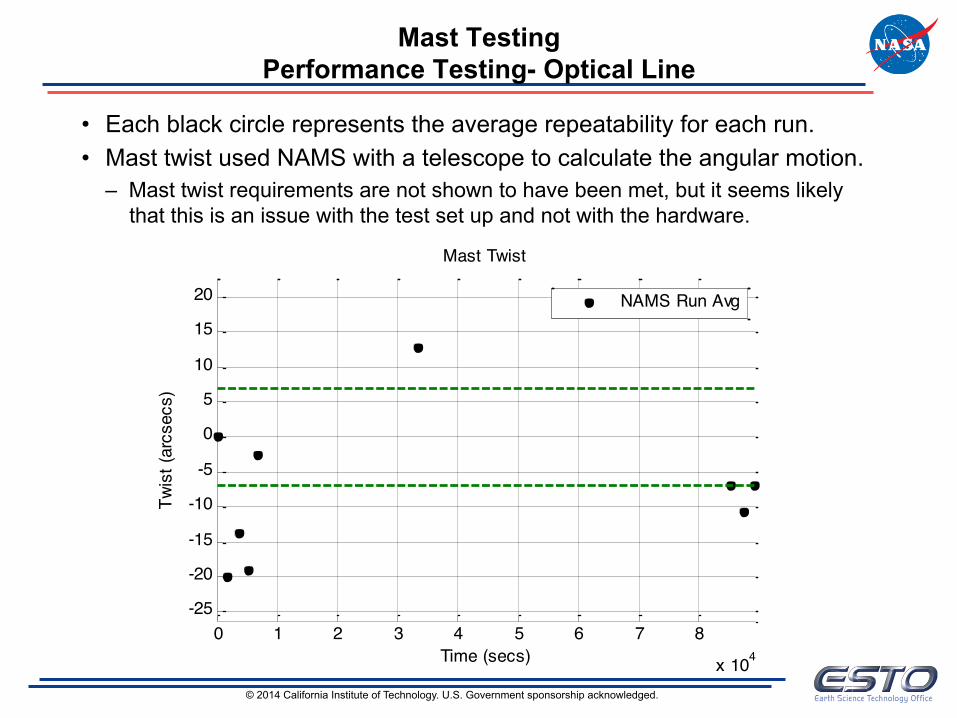
Mast Testing Performance Testing- Optical Line
• Each black circle represents the average repeatability for each run. • Mast twist used NAMS with a telescope to calculate the angular motion.
– Mast twist requirements are not shown to have been met, but it seems likely that this is an issue with the test set up and not with the hardware.
0 1 2 3 4 5 6 7 8
x 104
-25
-20
-15
-10
-5
0
5
10
15
20
Time (secs)
Twis
t (ar
csec
s)
Mast Twist
NAMS Run Avg

© 2014 California Institute of Technology. U.S. Government sponsorship acknowledged.
Mast Testing Performance Testing – Optical Line
• The gifs to the right show the noise in the measuring system. 18 frames of data are taken at 16fps of a motionless system. Ideally nothing should be moving.
• The float glass mirror seems to either be vibrating or its optical surface is not flat enough, causing an apparent motion as well as an inability to focus perfectly. – It appears to be moving when
the entire system should be stationary.
TeleNoHinge TeleWithHinge
Float Glass Mirror
Mas
t Tar
get
“Fix
ed” T
arge
t

© 2014 California Institute of Technology. U.S. Government sponsorship acknowledged.
Mast Testing Performance Testing
Optical Line
• The image on the left is from our calibration testing which also used float glass mirrors. – In the calibration testing, none of this “shimmering” was seen and much better focus was
able to be achieved using the same mirrors as in the mast twist performance testing. • It is unclear why this phenomenon occurred only in the mast testing and not in the
calibration and verification stages.
TeleNoHinge
Float Glass Mirror
Telescope Calibration
Float Glass Mirror
Float Glass Mirror

© 2014 California Institute of Technology. U.S. Government sponsorship acknowledged.
Lessons Learned
• NAMS (nano meter accurate measuring system) can be very accurate, but needs to be very carefully set up. – Need optically flat mirrors of ¼ wave or better. Float glass, while cheaper, unacceptably
affects results. – Cameras need very bright, very flat lighting to produce accurate results.
• Light intensity gradients across the image can affect accuracy. – Precise temperature control of the cameras is needed for accurate results. This makes it
difficult to use for thermal testing. – Best when used to make relative measurements between two targets within the same
camera field of view. Otherwise camera mount stability becomes the dominating motion. • Laser path shows random jitter.
– A more stable mount for the laser would be used in the future. – Jitter motion was able to be averaged out so did not affect performance results
significantly. • Offload GSE was hung from the ceiling while rest of the hardware was supported
from the optical table. – Even if the optical table was floated, vibrations could enter the system through the ceiling,
to the offload GSE, and to the hardware, introducing noise into the results. – Need to have fully self contained system that can be floated, i.e. support GSE from the
optical table instead of the ceiling.

© 2014 California Institute of Technology. U.S. Government sponsorship acknowledged.
Summary
• A full scale boom was designed fabricated and tested for the SWOT* KaRIn Instrument.
• Boom kinematics were demonstrated: – Hinge bodies were tested both at ambient and at temperature – Full Scale Deployment
• Test results indicate deployment repeatability of +/- 2.5 arcsecs – well within the SWOT* requirements (+/- 7.5 arcsecs)
• Analysis shows deployed frequency and stability requirements are met – SWOT* to test this winter
• Technology has successfully been transferred to the SWOT* project.
29
*Mission Concept – Pre-decisional – for Planning and Discussion Purposes Only

National Aeronautics and Space Administration Jet Propulsion Laboratory California Institute of Technology Pasadena, CA www.jpl.nasa.gov www.nasa.gov 30