acrobat - femci - nasa
TRANSCRIPT

DELIVERING INFORMATION ON DEMAND
VV EE RR II DD II AA NN E E NN GG II NN EE EE RR II NN GG DIVISION DIVISIONAeronautics SectorAeronautics Sector
VV EE RR II DD II AA NN E E NN GG II NN EE EE RR II NN GG DIVISION DIVISION
FEMCI Workshop 2001FEMCI Workshop 2001Innovative FEM Solutions to Challenging ProblemsInnovative FEM Solutions to Challenging ProblemsNASA Goddard Space Flight CenterNASA Goddard Space Flight CenterJim MaltbyJim Maltby 16 May 200116 May [email protected]
Practical External Utility Programs for Finite ElementModeling using SDRC I-DEAS Master Series
VERIDIAN ENGINEERING
2
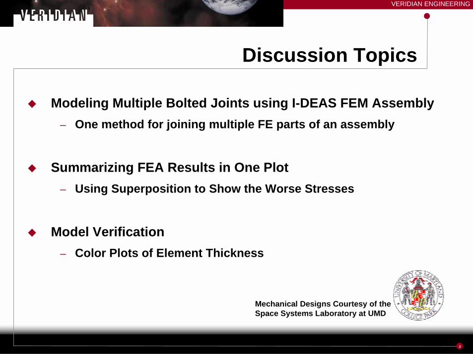
Discussion Topics
� Modeling Multiple Bolted Joints using I-DEAS FEM Assembly– One method for joining multiple FE parts of an assembly
� Summarizing FEA Results in One Plot– Using Superposition to Show the Worse Stresses
� Model Verification– Color Plots of Element Thickness
Mechanical Designs Courtesy of theSpace Systems Laboratory at UMD
VERIDIAN ENGINEERING
3
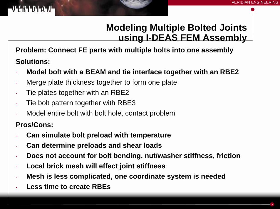
Modeling Multiple Bolted Jointsusing I-DEAS FEM Assembly
Problem: Connect FE parts with multiple bolts into one assemblySolutions:- Model bolt with a BEAM and tie interface together with an RBE2- Merge plate thickness together to form one plate- Tie plates together with an RBE2- Tie bolt pattern together with RBE3- Model entire bolt with bolt hole, contact problemPros/Cons:- Can simulate bolt preload with temperature- Can determine preloads and shear loads- Does not account for bolt bending, nut/washer stiffness, friction- Local brick mesh will effect joint stiffness- Mesh is less complicated, one coordinate system is needed- Less time to create RBEs
VERIDIAN ENGINEERING
4
RR
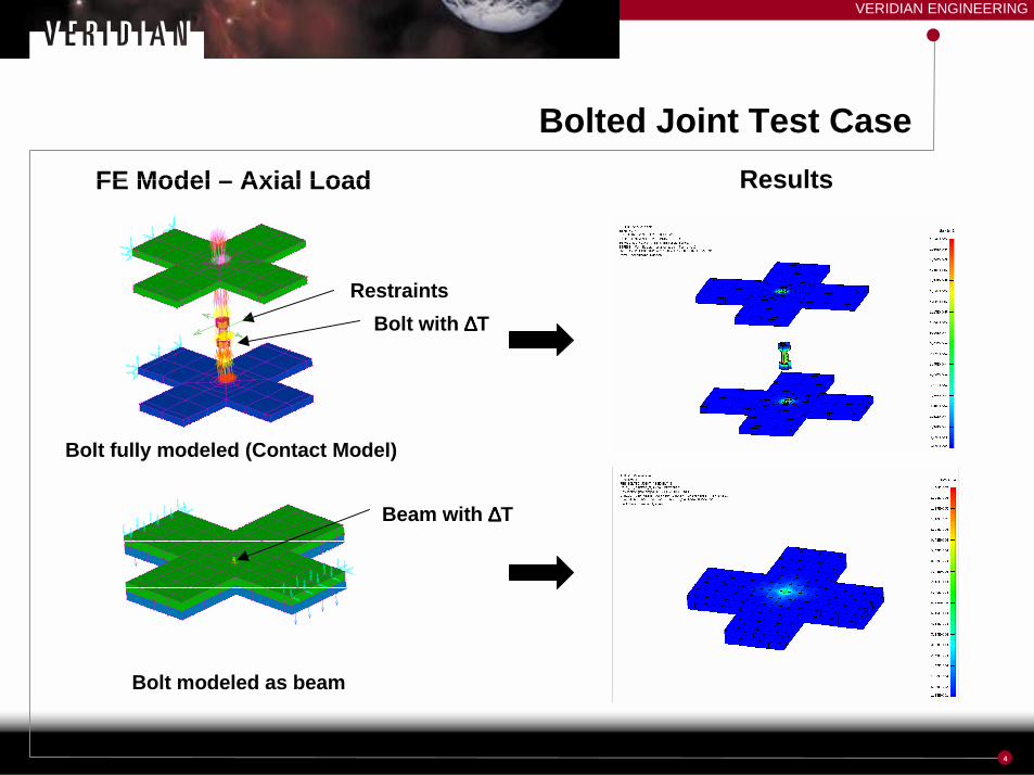
Bolted Joint Test CaseFE Model – Axial Load Results
Bolt modeled as beam
Bolt fully modeled (Contact Model)
MPMPMPMPMPMPMPMPMPMPMPMPMPMPMPMPMP MPMPMP
MPMPMPMPMPMPMPMPMPMPMPMPMPMPMPMP
MPMPMPMPMPMPMPMP MPMPMPMPMPMPMPMP
RestraintsBolt with ∆∆∆∆T
Beam with ∆∆∆∆T
VERIDIAN ENGINEERING
5
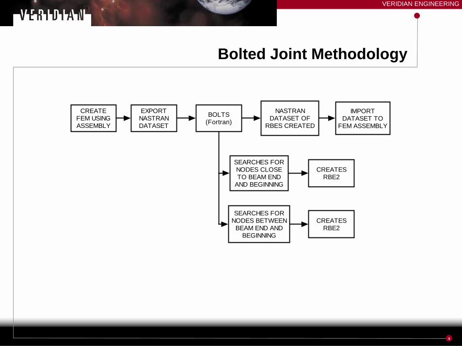
Bolted Joint Methodology
CREATEFEM USINGASSEMBLY
BOLTS(Fortran)
SEARCHES FORNODES CLOSETO BEAM END
AND BEGINNING
CREATESRBE2
EXPORTNASTRANDATASET
NASTRANDATASET OF
RBES CREATED
IMPORTDATASET TO
FEM ASSEMBLY
SEARCHES FORNODES BETWEEN
BEAM END ANDBEGINNING
CREATESRBE2

VERIDIAN ENGINEERING
6
07-May-01 13:33:45I-DEAS Master Series 7 : SimulationDatabase: D:\users\jmaltby\PFSS\PFSS4B.mf1 Units : INView : No stored View Display : No stored Option
Task : Master Modeler Model/Part Bin: ANALYSISModel: TEST FEM Parent Part: afmPt Assembly1
Bolted Joint - Example07-May-01 11:11:57I-DEAS Master Series 7 : Simulation
Database: D:\users\jmaltby\PFSS\PFSS4B.mf1 Units : INView : No stored View Display : No stored Option
Task : Meshing Model/Part Bin: ANALYSISModel: TEST FEM Parent Part: afmPt_Assembly1
07-May-01 13:41:21I-DEAS Master Series 7 : SimulationDatabase: D:\users\jmaltby\PFSS\PFSS4B.mf1 Units : INView : No stored View Display : No stored Option
Task : Master Modeler Model/Part Bin: ANALYSISModel: TEST FEM Parent Part: afmPt Assembly1Assembles Model
Assembled FEMs
Bolt FEMs
RBEs
Beam
261 Bolts
VERIDIAN ENGINEERING
7
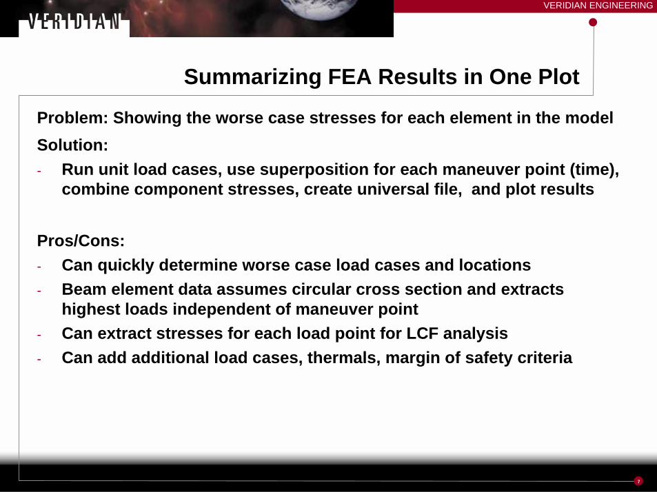
Summarizing FEA Results in One PlotProblem: Showing the worse case stresses for each element in the modelSolution:- Run unit load cases, use superposition for each maneuver point (time),
combine component stresses, create universal file, and plot results
Pros/Cons:- Can quickly determine worse case load cases and locations- Beam element data assumes circular cross section and extracts
highest loads independent of maneuver point- Can extract stresses for each load point for LCF analysis- Can add additional load cases, thermals, margin of safety criteria
VERIDIAN ENGINEERING
8
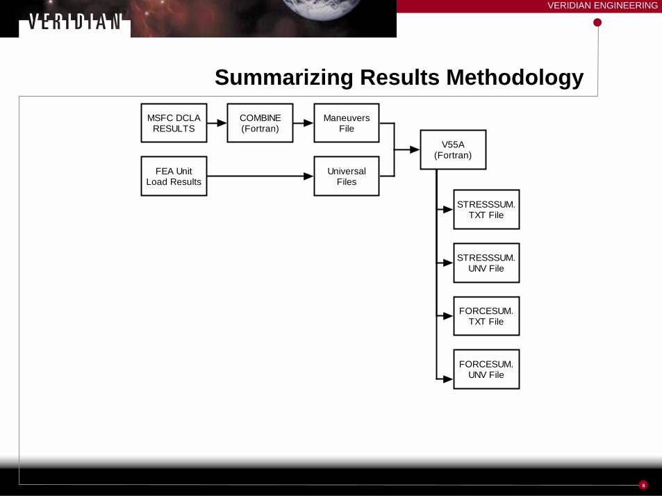
Summarizing Results MethodologyMSFC DCLA
RESULTSManeuvers
File
FEA UnitLoad Results
UniversalFiles
COMBINE(Fortran)
V55A(Fortran)
STRESSSUM.TXT File
STRESSSUM.UNV File
FORCESUM.TXT File
FORCESUM.UNV File
VERIDIAN ENGINEERING
9
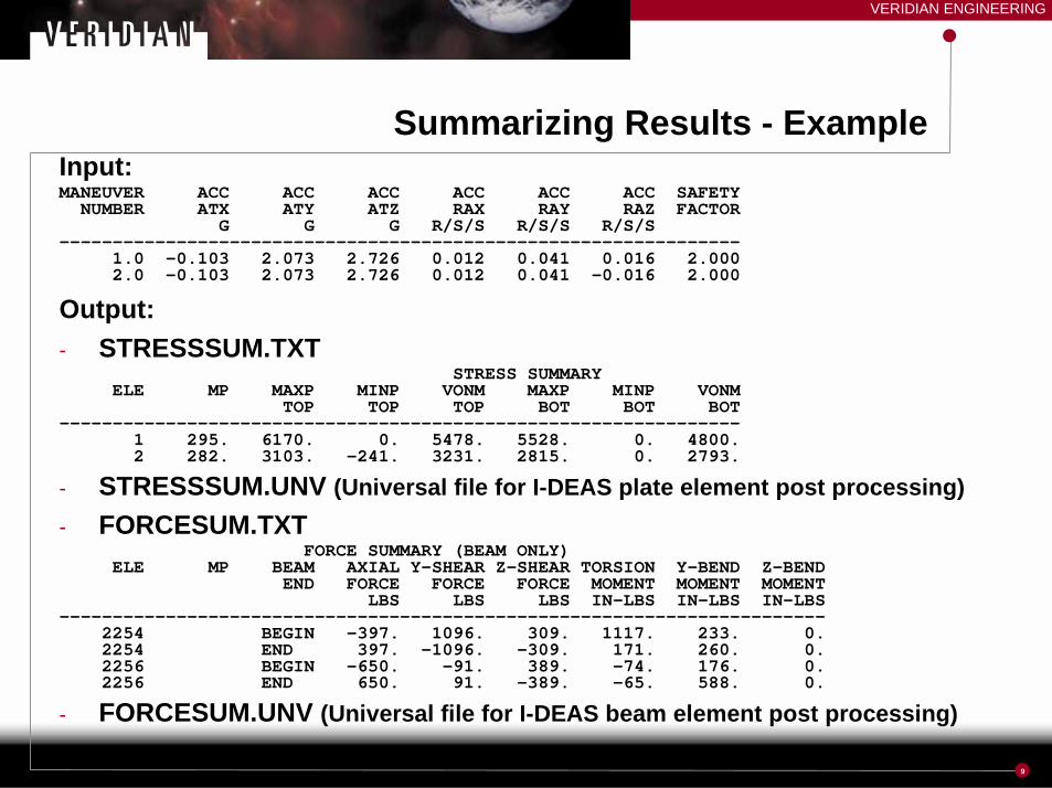
Summarizing Results - ExampleInput:MANEUVER ACC ACC ACC ACC ACC ACC SAFETY
NUMBER ATX ATY ATZ RAX RAY RAZ FACTORG G G R/S/S R/S/S R/S/S
----------------------------------------------------------------1.0 -0.103 2.073 2.726 0.012 0.041 0.016 2.0002.0 -0.103 2.073 2.726 0.012 0.041 -0.016 2.000
Output:- STRESSSUM.TXT
STRESS SUMMARYELE MP MAXP MINP VONM MAXP MINP VONM
TOP TOP TOP BOT BOT BOT----------------------------------------------------------------
1 295. 6170. 0. 5478. 5528. 0. 4800.2 282. 3103. -241. 3231. 2815. 0. 2793.
- STRESSSUM.UNV (Universal file for I-DEAS plate element post processing)- FORCESUM.TXT
FORCE SUMMARY (BEAM ONLY)ELE MP BEAM AXIAL Y-SHEAR Z-SHEAR TORSION Y-BEND Z-BEND
END FORCE FORCE FORCE MOMENT MOMENT MOMENTLBS LBS LBS IN-LBS IN-LBS IN-LBS
------------------------------------------------------------------------2254 BEGIN -397. 1096. 309. 1117. 233. 0.2254 END 397. -1096. -309. 171. 260. 0.2256 BEGIN -650. -91. 389. -74. 176. 0.2256 END 650. 91. -389. -65. 588. 0.
- FORCESUM.UNV (Universal file for I-DEAS beam element post processing)
VERIDIAN ENGINEERING
10
Summarizing Results - ExampleLocation of File
RESULTS: 1-RANGER TSX - LIFTOFF/LANDING ACCELERATIOSTRESS - MAX PRIN MIN:-4.72E+04 MAX: 1.17E+05 VALUE OPTION:ACTUALFRAME OF REF: PART
-4.72E+04
-3.07E+04
-1.43E+04
2.21E+03
1.87E+04
3.51E+04
5.16E+04
6.81E+04
8.45E+04
1.01E+05
1.17E+05
07-Nov-00 11:22:03I-DEAS Master Series 7 : SimulationDatabase: E:\users\JMaltby\MSFC_DCLA\DCLAMODELLOAD.mf1 Units : INView : No stored View Display : No stored Option
Task : Post Processing Model/Part Bin: MainModel: Fem1 Parent Part: Part1
Location of FileRESULTS: 1-FORCE-RANGER TSX - LIFTOFF/LANDING ACCELELEMENT FORCE - MAG MIN: 5.11E-10 MAX: 3.25E+04 VALUE OPTION:ACTUALFRAME OF REF: PART
5.11E-10
3.25E+03
6.51E+03
9.76E+03
1.30E+04
1.63E+04
1.95E+04
2.28E+04
2.60E+04
2.93E+04
3.25E+04
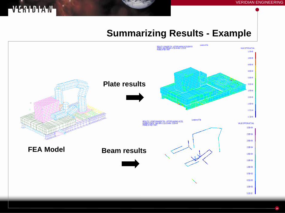
FEA Model
Plate results
Beam results

VERIDIAN ENGINEERING
11
Model Verification – Thickness PlotProblem: Checking plate element thickness via color plotSolution:- Export model to NASTRAN dataset, read CQUAD4/CTRIA3 and
PSHELL cards, write Universal filePros/Cons:- Can verify plate thickness graphically- Can verify plate thickness transitions

VERIDIAN ENGINEERING
12
Thickness Plot - Example
DS1
DS1
DS1
DS1
DS1
DS1DS1
DS1DS1
DS1DS1
DS1DS1
DS1
DS1DS1
DS1DS1
DS1DS1
DS1DS1
DS1DS1
DS1
DS1
DS1
DS1
DS1
DS1
DS1DS1
DS1DS1
DS1DS1
DS1DS1
DS1
DS1DS1
DS1DS1
DS1DS1
DS1DS1
DS1DS1
DS1
DT1DT1
DT1DT1DT1DT1
DT1DT1DT1
DT1DT1DT1
DT1DT1DT1
DT1DT1DT1DT1
DT1DT1
DT1
DT1DT1DT1DT1DT1DT1DT1
DT1DT1DT1DT1DT1DT1DT1DT1DT1
DT1DT1DT1DT1DT1
DT2DT2
DT2DT2DT2
DT2DT2
DT2DT2DT2
DT2DT2DT2
DT2DT2
DT2DT2DT2DT2
DT2
DT2DT2
DT2DT2DT2
DT2DT2DT2
DT2DT2
DT2DT2
DT2DT2DT2
DT2DT2DT2
DT2DT2
DT2DT2DT2
DT2DT2
DT2DT2DT2DT2
DT2
DT3DT3
DT3DT3DT3
DT3DT3
DT3DT3DT3DT3
DT3DT3
DT3DT3DT3DT3
DT3DT3DT3DT3DT3
DT3DT3
DT3DT3DT3
DT3
DT3DT3DT3DT3DT3DT3DT3DT3DT3DT3
DT3DT3DT3DT3DT3DT3DT3DT3DT3DT3
DT3DT3DT3DT3DT3
DT4DT4DT4DT4DT4
DT4DT4DT4DT4DT4
DT4DT4DT4DT4DT4
DT4DT4DT4
DT4DT4DT4
DT4DT4DT4DT4DT4
DT4DT4DT4DT4
DT4DT4DT4DT4DT4
DT4DT4DT4
DT4DT4DT4DT5DT5DT5DT5DT5DT5DT5DT5DT5DT5DT5DT5DT5DT5DT5
DT5DT5DT5DT5DT5DT5DT5DT5DT5DT5
DT5DT5DT5DT5DT5DT5DT5DT5DT5DT5
DT5DT5DT5DT5DT5DT5DT5DT5DT5DT5
DT5DT5DT5DT5DT5
DT6DT6DT6DT6DT6DT6DT6DT6DT6DT6DT6DT6DT6DT6DT6DT6DT6DT6DT6DT6DT6DT6DT6DT6DT6
DT6DT6DT6DT6DT6DT6DT6DT6DT6DT6DT6DT6DT6DT6DT6DT6DT6DT6DT6DT6DT6DT6DT6DT6DT6
Graphical Thickness Plot Color Band Thickness Plot