acquire store c ase stud y structural testing of …
TRANSCRIPT

2
C A S E S T U D YSTOREACQUIRE
STRUCTURAL TESTING OF ROCKET NOSE CONE
and test engineer, specializing in dynamics test, Mr. Domingos Strafacci – welcomed my two colleagues and me in the most friendly and cooperative manner. We came to work closely with them during the entire test procedure and enjoyed the sharing of know-how and experience.
DCTA functions as the Brazilian national military research center for aviation and space flight and subordinated to the Brazilian Air Force (FAB). DCTA coordinates all technical and scientific activities related to the aerospace sector in involving interests of the Ministry of Defense. The department was established in 1953 and currently employs a staff of several thousand people, civilian as well as military.
the three major global airplane production companies, Embraer, Boeing, and Airbus.
São José dos Campos also holds a wide range of both civil and military education and research institutions, including the Aeronautics Institute of Technology (ITA) – one of the most prestigious engineering schools in Brazil, the National Institute for Space Research (INPE), as well as DCTA, including Aeronautics and Space Institute (IAE).
Entering this area with its mixture of business and military development projects naturally requires more security checks. However, the IAE/DCTA team – leader of the group for dynamic tests, Dr. Edilson Camargo,
SINE PROCESSINGAERONAUTICS AND SPACE INSTITUTE (IAE), DCTA, BRAZIL
By Vid Selič, NVH engineer, Dewesoft
At the Aeronautics and Space Institute (IAE), DCTA, structural dynamic tests, like sine processing, SRS and modal analysis are performed as a part of the standard procedure on different components of rocket launch systems. In this case, the nose cone of a rocket was tested on a shaker using sine processing.Dewesoft X3 software improved the time efficiency and the quality of data acquired by supporting the real-time calculation of many parameters, such as responses in peak, RMS (Root Mean Square), THD (Total Harmonic Distortion), phase - all easily obtainable through the fast setup design and a designated Sine processing user interface.
The Departamento de Ciência e Tecnologia Aeroespacial (DCTA), the Brazilian Department of Science and Aerospace Technology is located in São José dos Campos – the largest Aerospacial Complex in all Latin America. The customer site is inside a large army base that boasts acres of tropical forest and very impressive infrastructure, ranging from universities to kindergartens, from supermarkets and restaurants to banks and recreational facilities - and even gas stations. The whole camp works as a city within the city and emanates an atmosphere of meticulous organization.
The overall complex is an industrial and research center covering the fields of energy, health, water and sanitation, railway, space, and aeronautics concentrating a range of major companies and industries, such as Panasonic, Johnson & Johnson, Ericsson, Philips, General Motors, Petrobras, and Monsanto.
The Technological Park, Parque Tecnológico de São José dos Campos, is the largest in the country, and the only research institute in the world that converges all

3
C A S E S T U D YSTOREACQUIRE
The goal was to perform the calculation of responses from a reference and seven triaxial accelerometers placed along the surface of the device under test. From the transfer functions between these responses and the reference, resonance frequencies can be obtained for verification of structure and its integrity/durability under the operational conditions it will endure during transport and actual space missions.
SINE PROCESSING
Sine processing is used whenever qualifying a large structure, such as a launch system (rocket) or payload (satellite). As this is a very meticulous industry and there is no room for error, all structures utilized during a mission must be carefully tested beforehand to ensure proper operation and uncompromised structural integrity.
Mechanical systems in real use cases cannot be idealized or simplified in means of assuming that masses are rigid bodies in which all points move in phase and that elastic elements have no mass. On the contrary, all real masses possess a certain elasticity and all spring elements have masses. Consequently, our device under test - which can be regarded as a beam from a mechanics point of view
Swedish Space Corporation (SSC). The TEXUS campaigns are either financed by ESA or jointly financed by DLR and ESA. The two-stage VSB-30 rocket was developed in collaboration with the Brazilian space organizations IAE, MORABA, and CTA (Centro Técnico Aerospacial), and SSC.
SSC is responsible for the launch operations and the actual launches are conducted from Esrange Space Center near Kiruna in Northern Sweden. The IAE part of the TEXUS missions focuses primarily on the development of the launch systems intended for and facilitating exploration of the properties and behavior of materials, chemicals, and biological substances under weightless conditions (micro gravitation). Each launch provides around six minutes of microgravity.
In this case, IAE needed to measure the resonance frequencies of their rocket nose cone in order to avoid operation in these frequencies, which could compromise the structural integrity and potentially cause mission failure. They already had detailed predictions of the operational frequency range of the structure – what they wanted was a reliable data acquisition system capable of tracking and computing the defined range of responses and transfer functions in real-time.
The DCTA has four institutes within its campus. Our testing took place at Instituto de Aeronaútica e Espaço (IAE), the Aeronautics and Space Institute. This institute develops and executes projects in the aeronautical, airspace and defense sectors, and is co-responsible for the execution of the Brazilian Space Mission.
The facilities at the DCTA are both modern and majestic in size since this is also the location of a rocket silo, where launch systems are built before being transported to the launch site in Sweden.
At the IAE there are a lot of ongoing R&D projects and the team had to steer between them - despite everything they managed to take part in every step of the rocket nose cone testing process without affecting their daily duties.
CUSTOMER ISSUE
The nose cone tested in this particular structural test plays an important role in R&D activities conducted for TEXUS missions - a sounding or research rocket program, serving the microgravity programs of the European Space Agency (ESA) and Deutsches Zentrum für Luft- und Raumfahrt e.V. (DLR), the German Aerospace Center.
The TEXUS program started in 1977 and is carried out jointly by DLR, EADS Astrium, Kayser-Threde and Different modes resulting from excitation in resonance frequencies.

4
C A S E S T U D YSTOREACQUIRE
At IAE/DCTA the Dewesoft X3 software – with the Sine processing plugin - and Dewesoft SIRIUS was used for the data acquisition. SIRIUS has been designed to be flexible, modular, expandable, and secure. The main goal of the development of SIRIUS and the X3 software has been to create a simple-to-use DAQ system that prevents frequent errors during the measurement process.
The Sine processing test runs by synchronizing the Dewesoft data acquisition system with the shaker controller (3rd party). By performing this synchronization in an exact manner, more acquisition channels can be utilized in the measurement system/sine processing plugin ensuring they are acquiring data simultaneously at the exact same frequency as the sine sweep test is being played on the shaker. COLA signal is necessary for this as it is output from the shaker controller as a constant amplitude voltage signal from which frequency is detected inside the Dewesoft sine processing plugin by performing one of the two methods of frequency detection; Zero-crossing or Hilbert transform.
The zero-crossing method detects the same direction passes (positive direction crossing of the y=0 axis) of the sine signal through zero value axis, meaning frequency is read every sine period. The zero-crossing method uses less computational resources but draws a non-smooth jagged graph of frequency vs. time. Hilbert transform, however, performs derivation of the phase difference between the sine signal and its cosine transformation, resulting in a smooth frequency versus time graph as it has continuous frequency information throughout the measurement. It yields better results in general and requires more computational power for execution.
Acquired signals from accelerometers placed on the rocket nose cone are measured together with sweep frequency which is detected from COLA signal. The zero-crossing method or Hilbert transform method can be simply applied by selecting them in the channel setup in the sine processing settings of Dewesoft X3 Software. For our particular application, COLA signal amplitude was set at 1V and the speed of sweep was set at 2Hz/second.
are being tracked by the plugin using COLA signal from the shaker. As desired output, Sine processing returns the structural resonance frequencies, amplitudes, phase, THD of response and also transfer functions between excitation and response points.
Sine processing uses a Constant Output Level Adaptor (COLA) signal to calculate instantaneous frequency and then extracts amplitude and phase from the accelerometers at that frequency. The COLA output signal synchronizes the shaker control system with the DAQ system. The COLA signal is a constant voltage sine wave which frequency tracks the Drive signal frequency during the Sine sweep test. Such testing is widely used for satellite design validation and qualification, and typically, hundreds of input channels are required.
Sine Sweep Vibration Testing traverses or sweeps from low to high frequency or vice versa. It is useful for identifying resonances inside the range of the sweep by comparing response vibrations of the product to the vibrations on the shaker table.
In order to evaluate the structure under test in the frequency domain, it is important to accurately extract frequency, amplitude, phase, orders and total harmonic distortion from a sinusoidal signal.
STRUCTURAL TESTING OF ROCKET NOSE CONE- represents a continuous combination of masses and springs.
Real mechanical systems like our DUT consists of an infinite number of elastic masses and springs and consequently also have an infinite number of resonances. Following from this it can be concluded that real-life mechanical systems have an infinite number of degrees of freedom. As far as terminology goes, when dealing with structures, this infinite number of resonances coming from the infinite number of degrees of freedom are usually denoted natural modes or simplified - modes.
Like all points in such real case continuous structures do not move in phase, a certain phenomenon occurs. Let us imagine the scenario of our structural tests where our structure/DUT is clamped on one side and freely moves on the other and is at the same time acted upon with a certain oscillating force (swept in time). Whenever the frequency of oscillating force concurs/corresponds with one of the DUT’s natural modes, a standing wave is formed as a consequence of the vibration pattern..
Sine processing is a tool to perform structural tests on large structures. An evaluation of such structures is done by exciting them with a sweep of single frequencies, that
5
C A S E S T U D YSTOREACQUIRE
and were working perfectly – the sine processing being no exemption.
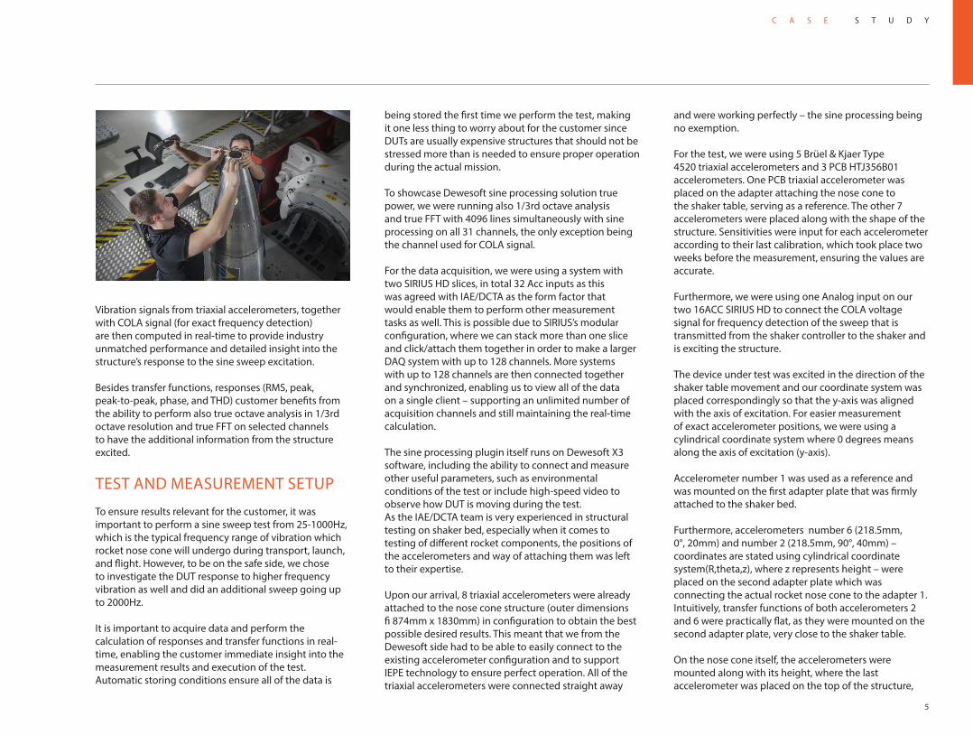
For the test, we were using 5 Brüel & Kjaer Type 4520 triaxial accelerometers and 3 PCB HTJ356B01 accelerometers. One PCB triaxial accelerometer was placed on the adapter attaching the nose cone to the shaker table, serving as a reference. The other 7 accelerometers were placed along with the shape of the structure. Sensitivities were input for each accelerometer according to their last calibration, which took place two weeks before the measurement, ensuring the values are accurate.
Furthermore, we were using one Analog input on our two 16ACC SIRIUS HD to connect the COLA voltage signal for frequency detection of the sweep that is transmitted from the shaker controller to the shaker and is exciting the structure.
The device under test was excited in the direction of the shaker table movement and our coordinate system was placed correspondingly so that the y-axis was aligned with the axis of excitation. For easier measurement of exact accelerometer positions, we were using a cylindrical coordinate system where 0 degrees means along the axis of excitation (y-axis).
Accelerometer number 1 was used as a reference and was mounted on the first adapter plate that was firmly attached to the shaker bed.
Furthermore, accelerometers number 6 (218.5mm, 0°, 20mm) and number 2 (218.5mm, 90°, 40mm) – coordinates are stated using cylindrical coordinate system(R,theta,z), where z represents height – were placed on the second adapter plate which was connecting the actual rocket nose cone to the adapter 1. Intuitively, transfer functions of both accelerometers 2 and 6 were practically flat, as they were mounted on the second adapter plate, very close to the shaker table.
On the nose cone itself, the accelerometers were mounted along with its height, where the last accelerometer was placed on the top of the structure,
being stored the first time we perform the test, making it one less thing to worry about for the customer since DUTs are usually expensive structures that should not be stressed more than is needed to ensure proper operation during the actual mission.
To showcase Dewesoft sine processing solution true power, we were running also 1/3rd octave analysis and true FFT with 4096 lines simultaneously with sine processing on all 31 channels, the only exception being the channel used for COLA signal.
For the data acquisition, we were using a system with two SIRIUS HD slices, in total 32 Acc inputs as this was agreed with IAE/DCTA as the form factor that would enable them to perform other measurement tasks as well. This is possible due to SIRIUS’s modular configuration, where we can stack more than one slice and click/attach them together in order to make a larger DAQ system with up to 128 channels. More systems with up to 128 channels are then connected together and synchronized, enabling us to view all of the data on a single client – supporting an unlimited number of acquisition channels and still maintaining the real-time calculation.
The sine processing plugin itself runs on Dewesoft X3 software, including the ability to connect and measure other useful parameters, such as environmental conditions of the test or include high-speed video to observe how DUT is moving during the test.As the IAE/DCTA team is very experienced in structural testing on shaker bed, especially when it comes to testing of different rocket components, the positions of the accelerometers and way of attaching them was left to their expertise.
Upon our arrival, 8 triaxial accelerometers were already attached to the nose cone structure (outer dimensions fi 874mm x 1830mm) in configuration to obtain the best possible desired results. This meant that we from the Dewesoft side had to be able to easily connect to the existing accelerometer configuration and to support IEPE technology to ensure perfect operation. All of the triaxial accelerometers were connected straight away
Vibration signals from triaxial accelerometers, together with COLA signal (for exact frequency detection) are then computed in real-time to provide industry unmatched performance and detailed insight into the structure’s response to the sine sweep excitation.
Besides transfer functions, responses (RMS, peak, peak-to-peak, phase, and THD) customer benefits from the ability to perform also true octave analysis in 1/3rd octave resolution and true FFT on selected channels to have the additional information from the structure excited.
TEST AND MEASUREMENT SETUP
To ensure results relevant for the customer, it was important to perform a sine sweep test from 25-1000Hz, which is the typical frequency range of vibration which rocket nose cone will undergo during transport, launch, and flight. However, to be on the safe side, we chose to investigate the DUT response to higher frequency vibration as well and did an additional sweep going up to 2000Hz.
It is important to acquire data and perform the calculation of responses and transfer functions in real-time, enabling the customer immediate insight into the measurement results and execution of the test.Automatic storing conditions ensure all of the data is

6
C A S E S T U D YSTOREACQUIRE
STRUCTURAL TESTING OF ROCKET NOSE CONE
As expected, the transfer function amplitudes are higher, the higher on the structure we are measuring. Consequently, the highest transfer function amplitude in resonance frequency is measured in the highest position, accelerometer 5. The second highest amplitude of transfer function is measured in the second-highest point, being accelerometer 4. Respectively, the lower we move along the measured positions towards the shaker table, the lower amplitudes of the transfer function between reference (accelerometer 1) and responses.
SOLUTION
IAE/DCTA is already using a designated system for the tests and is handling all the transfer function calculations in post-processing. As the Dewesoft sine processing plugin is able to handle the calculation of transfer functions, phase, RMS, Peak and a lot of other parameters in real-time, this feature presents an important benefit to the customer.As DUTs such as rocket launch systems and/or payloads are usually costly it is vital for IAE/DCTA to be able to see transfer functions in real-time during the test. Having results calculated in real-time enables IAE/DCTA engineers to have immediate insight into the measured parameters of the structure, allowing them to monitor if resonance frequencies and corresponding amplitudes are within or out of expected/projected values. They can immediately modify the excitation parameters or stop the test to prevent unwanted stress to be put on the device under test.
the tip of the nose cone. Accelerometers listed by height, coming from bottom to top of the structure:
Accelerometers listed from bottom to top of the structure: • Accelerometer 8 (218.5mm, 0°, 375mm)• Accelerometer 7 (218.5mm, 90°, 475mm)• Accelerometer 3 (218.5mm, 0°, 575mm)• Accelerometer 4 (192.25mm, 0°, 1000mm)• Accelerometer 5 (47.7mm, 0°, 1830mm)
The shape of the nose cone is tailored to aerodynamic efficiency and its profile is described by a curve. Consequently, it was important to mount accelerometers in the proper way, in order to have them acquire vibration in the axis of excitation. For this purpose, special mounting brackets aired with triaxial accelerometers were utilized and calculation was performed in the axis of excitation. Since the nose cone is symmetrical over its center axis, the same response is expected on both sides of the structure.
The positioning of the accelerometers: 7 on the rocket nose cone under test and 1 one the adapter plate attached to the shaker bed.
The highest transfer function amplitude in the resonance frequency is measured in the top position, accelerometer 5 - shown on the graph in orange. The second highest is measured at the second-highest point, being accelerometer 4 - turquoise color.
In measured frequency range from 25Hz-1000Hz, there are two very prominent and visible resonance frequencies. The first one was measured at 120Hz and is the resonance/natural frequency – corresponding with the first mode shape, whereas the second resonance frequency with the highest amplitude is measured at 325Hz – corresponding with the second mode shape. The third mode and resonance frequency

7
C A S E S T U D YSTOREACQUIRE
sine processing. Through this we will be able to optimize our cost expenditure”.
There is a general need for such high channel count systems – existing systems in daily use, often consisting of more than 1000 channels, computation done in real-time in every channel. A number of aerospace agencies worldwide could benefit from a system like this and our solutions have proven most suitable for the aerospace market.
On the last day of testing Edilson Camargo and Domingos Strafacci, gave us a tour around their premises. They took us to see their own garden where they grow a variety of fruits, vegetables and spices. With their minds set on space, they still keep a solid grounding on planet Earth.
such as parts of or entire launch system.
As DCTA research and development activities consist of many different projects, they are able to benefit greatly from the flexibility of Dewesoft system, that can be used to perform tasks ranging from road data vibration acquisition and GPS tracking of the route to performing modal analysis on the wing of a plane or measure SRS during rocket stages separation test.
As DCTA on a regular basis performs many additional measurements besides sine processing, the Dewesoft system is also the way to optimize cost. The same data acquisition system – or part of it – can for example, with added GPS input, be utilized also for vibration measurements on the trailer used to transport parts of launch systems (rockets).
The IAE dynamic tests leader, Dr. Edilson Camargo said:” As this system is very flexible it will enable us to tackle a variety of our day to day measurement tasks, not just
were measured at 730Hz. In order to ensure structural integrity during operation/flight, these resonance frequencies should be avoided as vibration amplitudes are highest here.
CONCLUSION
Dewesoft Sine processing plugin coupled with the powerful SIRIUS HD DAQ system is able to perform testing of large structures in real-time on an unlimited number of channels. Should there be a later need to perform additional calculations, not selected to be performed in real-time during the test, they can be performed in post-analysis using the time domain data that was stored during the measurement. Dewesoft supports this with an offline math function, complete sine processing plugin and all functionalities included.
IAE Test engineer, Domingos Strafacci concluded: “The system is really easy to use and setup. It will save us a lot of time when performing this kind of crucial structural testing”.
The measurement that took place in this case was only using a single of many nodes that would otherwise be building a larger system. For the initial measurement, we decided to go with a smaller channel count for logistic purposes. It must be noted however, that regardless of the number of channels the operational properties of the system will remain unchanged.
In the future, DCTA needs a 320-channel channel count DAQ system to enable their shaker to perform structural tests – sine processing and modal – on large devices,
Sweeping from 25 - 2000Hz confirms that resonance frequencies with highest amplitudes are found at low frequencies