acoustical noise problems in production test and ... · pdf file29.11.2009 ·...
TRANSCRIPT

1
Acoustical Noise Problemsin Production Test
of Electro Acoustical Units and Electronic Cabinets
Birger SchneiderNational Instruments Engineering ApS, Denmark
A National Instruments Company
2
Presentation Outline
• What is Rub & Buzz?• What type of products show rub & buzz problems? • The nature of rub & buzz• Finding ways to reduce the effects of surrounding noise, when
measuring rub & buzz• Tools for testing rub & buzz• Setting limits• An example

3
Irregular Disturbances Causing Undesirable Noise
• Many products, e.g. consumer electronics products show irregular, transient disturbances, caused by mechanically artifacts, resulting in acoustical noise problems
• We often refer to such effects by the term “Rub & Buzz”
• Rub & buzz testing is about electro-acoustical testing of audio disturbances caused by rub & buzz and other unwanted, irregular nonlinear distortion effects.
• Rub & Buzz problems are caused by mechanical or structural defects in a broad range of products.
4
Rattle Noise / Rub & Buzz• A variety of consumer products possess potential undesirable
mechanical based acoustical noise unacceptable/ irritating to the consumer, e.g. in products like:
TV setsLoudspeakers/transducers in mobile phonesCompressorsHearing aidsComputers (blower activated)Automotive partsElectric drivesEtc.

5
Rub & Buzz in Our Daily Life
• The phenomena of rub & buzz are a part of our daily life, sometimes more annoying than other times.
• Most people have experienced rub & buzz effects in various situations, e.g.:
Irritating noise from a compressor in a fridge in our kitchen starting or stopping A motor or fan runningRattling noise in an automobile when driving at certain speedTV cabinet rattling, when sound is set to a certain levelRub & buzz issues in loudspeakers are most annoying, since a loudspeaker is intended to amplify quality sound and not irritating noise.Etc.
6
Common Loudspeaker Type• A common type of driver uses a lightweight diaphragm, or cone, connected to a
rigid basket, or frame, via a flexible suspension that constrains a coil of fine wire to move axially through a cylindrical magnetic gap.
Source: Wikipedia

7
Manufacturing Defects in Loudspeakers
Mechanical artifacts in loudspeakers may be caused by:
• Loose particles between the coil and the magnet or in front of the diaphragm
• Distorted coils scraping the pole piece or the top plate• Cracks or holes in the diaphragm• Incorrect assembly, lack of adhesives for the diaphragm • Wire leads beating the diaphragm• Loudspeaker enclosure/cabinet shortcomings like missing screws,
untightly screws/fasteners, poor plastic moldings, etc.)• Other production or component aging problems
8
No Direct Correlation to Stimulus
• Rub & buzz effects are typically not pure harmonics of the fundamentals but appear as small glitches or transients.
• In e.g. a loudspeaker, rub & buzz is often a result of high displacement of the loudspeaker, which tends to take place close to 1 kHz.
• The human ear has its highest sensitivity around the same frequencies.
• The glitches may not appear at the stimulus frequency but appear at higher harmonics and cannot be directly correlated to the input stimuli.

9
Nature of Rub & Buzz Artifacts
• The artifacts themselves are sharp changes, clicks and glitches, in other words short energy pulses in the time domain.
• It means that frequency excitations are required to activate a time domain anomaly.
• Due to the nature of the artifacts, traditional spectral analysis methods like FFT and tracking filters are less useful for disclosing rub & buzz artifacts, since such methods include elements of averaging and settling, which tend to suppress the detection of short transient.
10
Rattle Noise / Rub & Buzz• Class of non-linear, irregular, impulsive and unwanted distortion effects,
which are not normally found with regular units.• Typically produced by mechanical and structural defects in the UUT.• Due to short pulsed of very low energy traditional methods like RMS-
FFT, THD methods are useless.
-1.5
-1
-0.5
0
0.5
1
1.5
-0.3
-0.2
-0.1
0
0.1
0.2
0
0.1
0.2
0.3
Glitch in Signal
Time Time Time
Ampl. [V] [d f(t)/dt] [Abs( d f(t)/dt)]
Steepness Absolute (Steepness)

11
Chirp Stimuli• The test stimuli signal must contain the frequencies that are likely to
excite the anomaly nature of the mechanical defects in question.
• A gliding sweep, also known as the chirp signal, is the optimal stimulus signal for this.
• The chirp signal continuously increases the signal frequency over the band of frequencies adapted for the analysis.
• A chirp signal is also well suited in the context that some mechanical artifacts in e.g. loudspeakers are best revealed in the beginning of a new frequency.
12
R&B Registered at Frequency of Occurrence
• Stimuli frequencies in the chirp signal are not necessarily correlating directly to the frequency bands of analysis.
• A stimulus tone at 200 Hz may excite some glitches at or close to some higher harmonics.
• For another tone the relationship can be different due to the non-linear nature of the rub & buzz phenomena.
• The analysis bands in our rub & buzz test method are taking the results of the analysis and categorizing the results to the frequency band, where they occurred.

13
Stimuli to be Optimized to Products and Manufacturing Process
• The start of the excitation stimuli (chirp signal) should at least be below the resonance frequency of the loudspeaker
• The stop frequency of the chirp signal should be high enough to stimulate most of the possible mechanical artifacts.
• The physical nature of manufacturing processes varies significantly from product to product and thus typically causes rather different artifacts and resulting sound responses (product type, manufacturing approach, etc.)
14
False Rejects Due to Noise
• A common problem in rub & buzz test is that noise from surroundings influences a measurement result and may be cause that given tests exceed their limits.
• If the test is repeated, the noise may no longer be present, and the test may thus pass.
• “False calls”, or “false rejects”, are challenges in testing of rub and buzz, not least in more noisy environments.
• A way to reduce the effects of false rejects is to repeat the test, and if it passes the second time, allow the test to pass.
15
The Elements of R&B Testing
Successful rub & buzz testing includes 3 vital elements:
• Detection: A tool, e.g. AudioMASTER & rub-buzz option, that allows detection of time domain noise transients/glitches.
• Selecting good/bad populations: A process of identifying subjective audio quality for a representative set of “good” and “bad” units from the population of units of interest.
• Setting limits: Will ensure statistical relationship between detected physical defects and the determined subjective audio quality (inAudioMASTER using the Limit Generator support tool)
16
Challenge of Setting Limits
• Setting limits for rub & buzz testing is not as straightforward as setting limits for traditional electrical parameters of testing a loudspeaker or similar consumer electronic products.
• Limits are closely linked statistically to the subjective audio qualityaimed at by the manufacturing company
• Limits in rub & buzz rely extensively on inherent characteristics of a given type of loudspeaker and its manufacture, including the production technology, process control, the general quality level, and several other factors.

17
Professional Approach to Limit Settings
• Correlate the limit settings with an extensive listen-in process.
• A population of typically a few hundred well-defined “good” units should be selected and a somewhat similar population of rejects parts is included, sometimes less.
• The two categories of units may be defined by a group of listeners with “golden ears”, i.e. people that have a good sense for listening to and identifying the characteristics of rub & buzz phenomena.
• The test is subjective, but is based on well-founded experience.
• Using more people for checking the test sample population ensures a good consistency in the definition of “good” and “bad” units.
18
Segregation of “Good” and “Bad”• If the results of a given
frequency band index are uncertain in terms of segregating the populations of good and bad parts:
A limit cannot be set that will promise an optimal separation in the subsequent production runs.
Good Segregation
Reduced Segregation
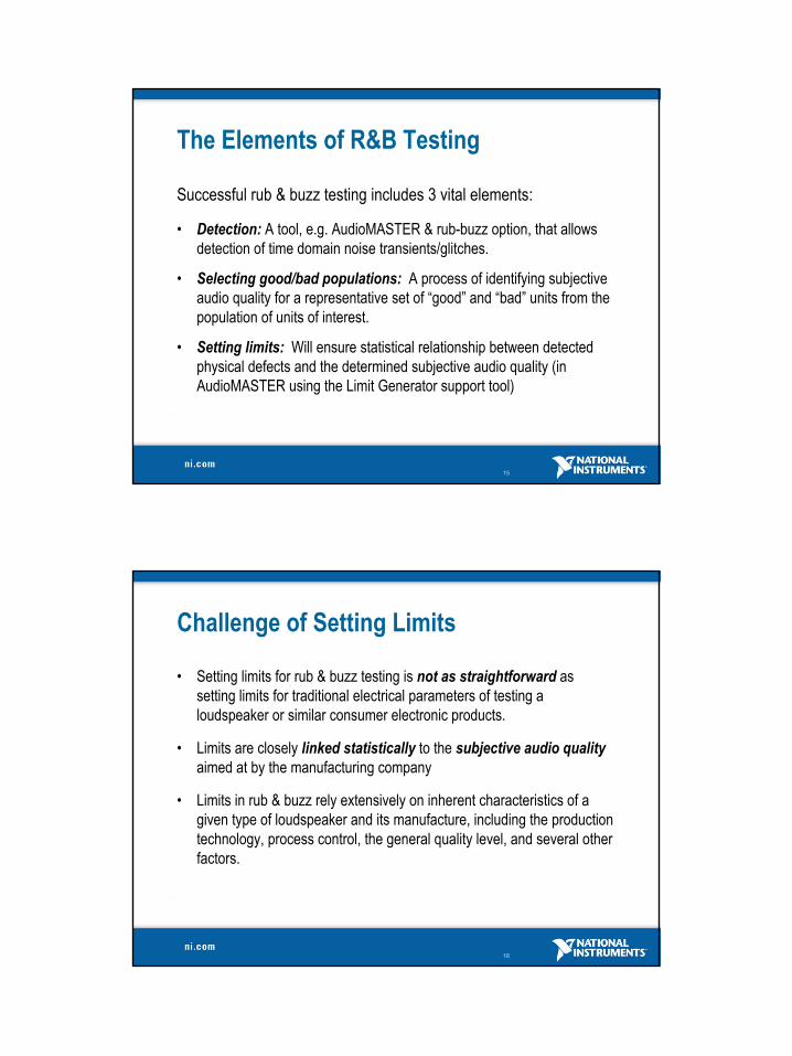
19
Setting Stimuli & Analysis
• The generation is set for Start and Stop values.
• Additional characteristics for the stimuli may be set.
• Frequency bands selected are for the detection bands.
20
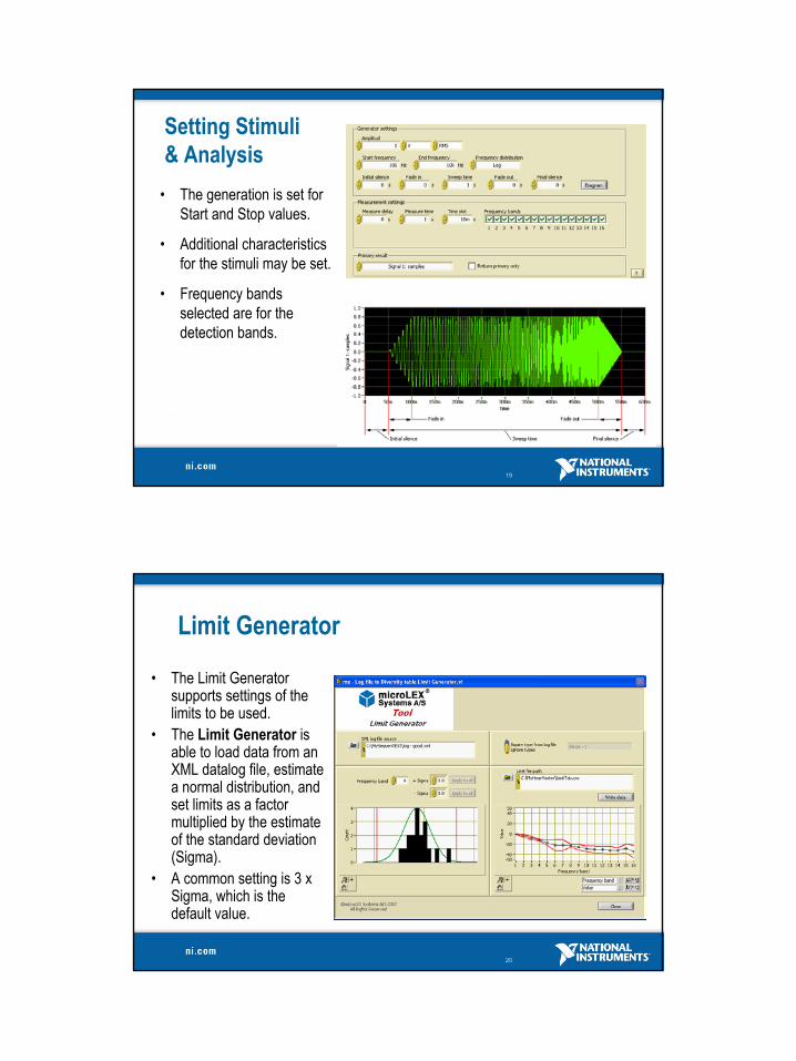
Limit Generator
• The Limit Generator supports settings of the limits to be used.
• The Limit Generator is able to load data from an XML datalog file, estimate a normal distribution, and set limits as a factor multiplied by the estimate of the standard deviation (Sigma).
• A common setting is 3 x Sigma, which is the default value.

21
Segregation of “Good” and “Bad”
• Limits are set for every frequency band and the spread of limits may be set individually for every band or applied with a common setting for all bands.
• Two sets of limits, one for the good population and one for the “bad” population must be compared to identify clear segregation.
• Some frequency bands, here e.g. 5-10, risk having relatively poor segregation,
Good
Bad
22
Detection of Mechanical Noise (Rattle)• A fully automatic approach to qualify and identify sound and
remove undesirable noise (rattle).
ProductionLine Control
Production line
Accelerometer RattleSPY
Unit Under Test(UUT)
AudioMASTER& add-on
Rub & BuzzAlgorithm
23
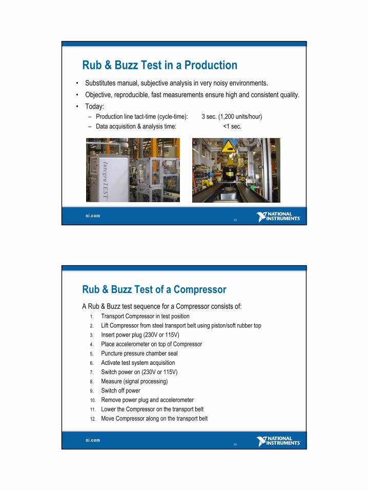
Rub & Buzz Test in a Production• Substitutes manual, subjective analysis in very noisy environments.• Objective, reproducible, fast measurements ensure high and consistent quality.• Today:
– Production line tact-time (cycle-time): 3 sec. (1,200 units/hour)– Data acquisition & analysis time: <1 sec.
24
Rub & Buzz Test of a CompressorA Rub & Buzz test sequence for a Compressor consists of:
1. Transport Compressor in test position2. Lift Compressor from steel transport belt using piston/soft rubber top3. Insert power plug (230V or 115V)4. Place accelerometer on top of Compressor5. Puncture pressure chamber seal6. Activate test system acquisition7. Switch power on (230V or 115V)8. Measure (signal processing)9. Switch off power10. Remove power plug and accelerometer11. Lower the Compressor on the transport belt12. Move Compressor along on the transport belt
25
To Learn More
• Contact:National Instruments Engineering ApSDr. Neergaards Vej 5CDK-2970 HoersholmDenmarkPhone: +45-45 76 21 00Fax: +45-45 76 22 00Email: [email protected]: www.ni.comContact : Birger Schneider