acoustic emission techniques standardized for … emission techniques standardized for concrete...
TRANSCRIPT
J. Acoustic Emission, 25 (2007) 21 © 2007 Acoustic Emission Group
ACOUSTIC EMISSION TECHNIQUES STANDARDIZED FOR
CONCRETE STRUCTURES
MASAYASU OHTSU, TOSHIRO ISODA and YUICHI TOMODA*
Graduate School of Science & Technology and *Faculty of Engineering, Kumamoto
University, Kumamoto, Japan
Abstract
Acoustic emission (AE) techniques have been extensively applied to concrete structures.
Results achieved are currently going to be standardized for the inspection and evaluation of in-
frastructures in service. Test results associated with these standardization activities for concrete
structures are discussed. In order to assess the damage levels of the structures, the Japanese So-
ciety for Non-Destructive Inspection has established the recommended practice (NDIS 2421).
Two AE indices of load ratio and calm ratio are defined for qualification of the damages. It is
demonstrated that damages qualified are in good agreement with actual damages of reinforced
concrete members. AE behavior of concrete under compression could be analyzed, applying the
rate process analysis. By evaluating intact moduli of elasticity from AE database, relative dam-
ages of concrete cores taken from a road bridge are quantitatively estimated.
The Federation of Construction Materials Industries, Japan, has recently published new stan-
dards on estimation of concrete properties by the elastic-wave methods. The standards contain a
monitoring method for active cracks in concrete by AE (JCMS-III B5706). The classification of
cracks is successfully applied to investigate the corrosion process of reinforcing steel-bars in
concrete. The moment tensor analysis of AE can identify cracking kinematics of location,
crack-type and crack orientation, which has been implemented as SiGMA procedure. Nucleation
of micro-cracking due to the expansion of corrosion product is studied. It is found that the
mechanisms of corrosion cracking at the meso-scale are really made up of tensile, shear and mi-
xed-mode cracks, while the surface crack and the diagonal cracks of mode I are observed at the
macro-scale. These results will form the basis for proposing RILEM recommendations.
Keywords: Concrete, damage, corrosion, moment tensor analysis.
1. Introduction
Concrete structures in service deteriorate due to heavy traffic loads, fatigue, aging, chemical
reactions and natural disasters. It is now recognized in concrete engineering that concrete struc-
tures are no longer considered maintenance-free, and a number of the structures are going to
reach their service-life limit. Accordingly, diagnostic inspections on the current state of deterio-
rated structures have been carried out all over the world. However, the assessment of damage or
structural integrity in existing structures is neither an easy task nor fully standardized yet. In this
regard, the recommended practice by acoustic emission (AE) is currently published (NDIS 2421,
2000), prescribing one criterion to assess the damage of reinforced concrete in service. Here,
results applied to bending tests of reinforced concrete beams (Ohtsu et al., 2002) are discussed.
Damage evaluation in concrete by AE activity of a core sample in a compression test is under
investigation (Ohtsu and Watanabe, 2001). AE activity is analyzed as the rate process, and the
damage parameter is evaluated by applying damage mechanics. Correlating AE rate with the
damage parameter, a database has been so successfully created that relative damages of concrete

22
samples are quantitatively estimated. The procedure is applied to concrete cores taken from a
road bridge.
The corrosion of reinforcing steel-bars in concrete can occur due to chloride attack. So far it
has been referred to as the most serious deterioration of reinforced concrete. An applicability of
AE technique to corrosion monitoring is discussed, applying the code by the Federation of Con-
struction Materials Industries, Japan (JCMS-III B5706, 2003).
The moment tensor analysis of AE is available for identifying crack kinematics of location,
crack-type and crack orientation (Ohtsu, 2000). The analysis is implemented as SiGMA (Sim-
plified Green’s functions for Moment tensnor Analysis) procedure. 3-D visualization has been
developed by using VRML (Virtual Reality Modeling Language) (Shigeishi and Ohtsu, 2003).
Mechanisms of corrosion cracking in concrete at the meso-scale identified by SiGMA are com-
pared with those at the macro-scale.
Currently, another standardizing action is in progress. RILEM TC212-ACD (Technical
Committee on Acoustic emission and related NDE for Crack detection and Damage evaluation in
concrete) has been established for proposing RILEM recommendations. All results discussed are
closely associated with this committee activity.
2. AE Techniques under Standardized Action
(1) Damage Qualification
The concrete structure is structurally stable with high redundancy, as AE activity is low in a
sound structure. Since the Kaiser effect is closely associated with structural stability, ratios to
qualify the damage are defined in the recommended practice (NDIS 2421), as follow;
(a) Ratio of load at the onset of AE activity to previous load:
Load ratio = load at the onset of AE activity in the subsequent loading / the previous load.
(b) Ratio of cumulative AE activity during the unloading to that of the maximum loading cycle:
Calm ratio = the number of cumulative AE activity during the unloading / total AE activity
during the whole cycle.
The load ratio can become larger than 1.0 in a sound structure. Due to damage accumulation,
the ratio decreases to below 1.0, generating AE counts at lower loading levels than before. AE
activity during unloading is another indication of structural instability. In the case of the sound
structure, AE activity is seldom observed and the calm ratio is small. In heavily damaged struc-
tures, load ratio is below 1.0 and calm ratio is large. In the recommendation, the damage is de-
fined as minor, intermediate and heavy as shown in Fig. 1.
(2) AE Rate Process Analysis
AE behavior of a concrete sample under compression is closely associated with nucleation of
micro-cracks. These cracks are gradually accumulated until final fracture, as the number of AE
counts due to nucleation of these cracks increases. Since the process could be referred to as sto-
chastic, the rate process theory has been introduced (Ohtsu and Watanabe, 2001). The following
equation of the rate process is derived to formulate the number of AE events, dN, due to the in-
crement of stress from V to V + dV,
dVVfN
dN )(= , (1)
where N is the total number of AE events and ƒ(V) is the probability function of AE activity at
stress level V(%). Here, a hyperbolic function ƒ (V) is assumed,

23
Fig. 1 Damage qualification by the load ratio and calm ratio.
Fig. 2 Result of AE rate process analysis. Fig. 3 Relation between rate ‘a’ and freeze-thaw
cycles.
bV
aVf +=)( , (2)
where a and b are empirical constants. ‘a’ is here called the rate, since it reflects AE activity at a
given stress level. It is found that the rate could increase due to accumulation of the mi-
cro-cracks in concrete. Substituting Eq. 2 into Eq. 1, a relationship between total number of AE
events N and stress level V is obtained as,
)exp(bVCVNa
= , (3)
where C is the integration constant. We have applied Eq. 3 to AE generating behavior of a con-
crete sample in a compression test. Approximating the probability function by Eq. 2, AE gener-
ating behavior is modeled. A relation between total AE counts and compressive stresses in a
standard sample (10-cm diameter and 20-cm height) is shown in Fig. 2. The sample was dam-
aged with 50 cycles of freeze-thaw action. It is demonstrated that AE generating behavior ob-
served in the test is in good agreement with the relation approximated by Eq. 3. We focused on
the rate ‘a’, because the value could reflect the damage degree. During the freezing and thawing
of concrete samples, where temperature was varied from 5oC to -15
oC for 3 hours, a relation be-
tween the rate “a” and the number of cycles was examined. Results are given in Fig. 3. It is
clearly observed that the rate ‘a’ increases from a negative value to a positive value with the in-
crease in freeze-thaw cycles. Thus, it is confirmed that the rate ‘a’ is a sensitive parameter to the
damage degree.

24
Fig. 4 (a) Stress-strain relation and (b) the corresponding damage-evolution process.
Fig. 5 Database on the damage evolution and the rate ‘a’.
A damage parameter in continuum damage mechanics is defined as a relative ratio of the
modulus of elasticity,
*1
EE= (4)
where E is the modulus of elasticity of concrete and E* is the intact modulus of elasticity. In the
compression test of a concrete sample, a relation between stress and strain is obtained as shown
in Fig. 4(a). The modulus varies from initial modulus E0 to final modulus Ec. The former is a
tangential modulus and the latter is a secant modulus. Then, the initial damage o is defined as,
*1 0
E
Eo = . (5)
Corresponding to the stress-strain relation, the damage parameter increases from o to c as
shown in Fig. 4(b). In order to estimate the initial damage o in Eq. 5, it is essential to obtain
the intact modulus E*. Because the rate ‘a’ is sensitive to the damage degree, a database on a
correlation between the damage evolution during the compression test, ln(Eo Ec), and the rate
‘a ‘ has been constructed as shown in Fig. 5. Most of the data are based on results of the freez-
ing and thawing tests of concrete samples. Assuming a linear correlation, it is derived as,
ln(Eo Ec) = ln[E * ( c o)] = Da +Y . (6)

25
After adding the data of a tested sample to the database, a new linear correlation of Eq. 6 is de-
termined. Then, it is assumed that E0 = E* when a = 0. This allows us to estimate the intact
modulus E* of the sample from,
)exp(* YEcE += . (7)
Then a relative damage of the sample is estimated as Eo/E*.
(3) AE Parameter Analysis
AE parameters obtained by a conventional system are AE count, AE hit, AE event, peak am-
plitude, AE energy, rise time, duration, arrival time differences in AE sensor array and so forth.
In order to classify active cracks, AE indices of RA value, and the averaged frequency Fa are
defined from parameters as (JCMS-III B5706),
RA = the rise time / the maximum amplitude. (8)
Fa = AE ringdown-count / the duration time, (9)
By means of these two indices, cracks could be classified into tensile and shear cracks as refer-
ring to Fig. 6. Tests were conducted in tensile tests and direct-shear tests of concrete samples, by
employing three AE sensors of different resonances. It is observed that crack types are reasona-
bly classified. Here, the classification shall be based on the moving average of more than 50
counts.
Fig. 6 Relationship between average frequency Fa and RA values for crack classification.
(4) SiGMA Analysis
In order to determine the moment tensor of an AE source, a simplified procedure has been
developed. This is suitable for a PC-based processor as it is robust in computation. The
procedure is implemented as SiGMA (Simplified Green's functions for Moment tensor Analysis)
(Ohtsu, 2000). Displaying AE waveform on CRT screen, two parameters of the arrival time and
the amplitude of the first motion are determined. In the location procedure, source location is
determined from the arrival time differences. Then, distance and its direction vector are deter-
mined. From the amplitudes of the first motions at more than 6 channels, the moment tensor is
determined. Since the SiGMA code requires only relative values of the moment tensor compo-
nents, the relative calibration of the sensors is adequate. Then, the classification of a crack is
performed by the eigenvalue analysis of the moment tensor. Setting the ratio of the maximum
shear contribution as X, three eigenvalues for the shear crack become X, 0, -X. Likewise, the

26
ratio of the maximum deviatoric tensile component is set as Y and the isotropic tensile compo-
nent as Z. Three eigenvalues are normalized and decomposed;
Normalization 1.0 = X + Y + Z,
the intermediate eigenvalue/the maximum eigenvalue = 0 - Y/2 + Z, (10)
the minimum eigenvalue/the maximum eigenvalue = -X - Y/2 + Z,
where X, Y, and Z denote the shear ratio, the deviatoric tensile ratio, and the isotropic tensile
ratio, respectively. In the present SiGMA code, AE sources of which the shear ratios are less
than 40% are classified into tensile cracks. The sources of X >60% are classified into shear
cracks. In between 40% and 60%, cracks are referred to as mixed mode. In the eigenvalue ana-
lysis, three eigenvectors e1, e2, and e3,
e1 = l + n
e2 = l x n (11)
e3 = l – n,
are also determined. Vectors l and n, which are interchangeable, are recovered. In order to vi-
sualize these kinematical information of AE source (crack), VRML is introduced (Shigeishi and
Ohtsu, 2003). Crack modes of tensile, shear and mixed-mode cracks are given in Fig. 7. Here,
an arrow vector indicates a crack motion vector l, and a circular plate corresponds to a crack
surface, which is perpendicular to a crack normal vector n.
(a) tensile crack (b) shear crack (c) mixed-mode
Fig. 7 3-D display models for tensile, shear, and mixed-mode cracks.
3. Results and Discussion
(1) Qualified Damage in Reinforced Concrete
For damage qualification, reinforced concrete beams of 3.2 m length were tested. Compres-
sive strength of concrete after 28-day moisture curing was 31.1 MPa. These beams were made
without lateral reinforcement. Two-point loading spans were varied as 0.65 m and 1 m with 2.84
supporting-span shown in Fig. 8. AE sensor of 150-kHz resonance frequency (PAC: R15) was
selected. Frequency range was set from 10 kHz to 1 MHz, and the total amplification was 80
dB. For event-counting, a threshold level was set to 50 dB. The measuring system was a MIS-
TRAS-AE system (PAC). After cracks were nucleated, clip gauges were attached to the speci-
men and the crack-mouth opening displacements (CMOD) were recorded.

27
Fig. 8 Sketch of a reinforced concrete beam.
Fig. 9 Qualified damages by the load ratio and the calm ratio.
For each loading cycle, the load ratio and the calm ratio were determined. Results are shown
in Fig. 9. Based on the maximum CMOD observed in the loaded beams, classification limits are
set as 0.9 for the load ratio and 0.05 for the calm ratio. This is because the serviceability limit of
the CMOD in the concrete structure is referred to as less than 0.1 mm in the standard specifica-
tion and the Kaiser effect was not observed in the case of the CMOD over 0.1 – 0.2 mm (Ohtsu,
1995). Into three zones of the minor, intermediate, and heavy damage, results of the maximum
CMODs are classified reasonably well. It demonstrates that the damage levels of reinforced
concrete beams can be qualified from the values of the load ratio and the calm ratio by monitor-
ing AE activity under cyclic loading or traffic loads.
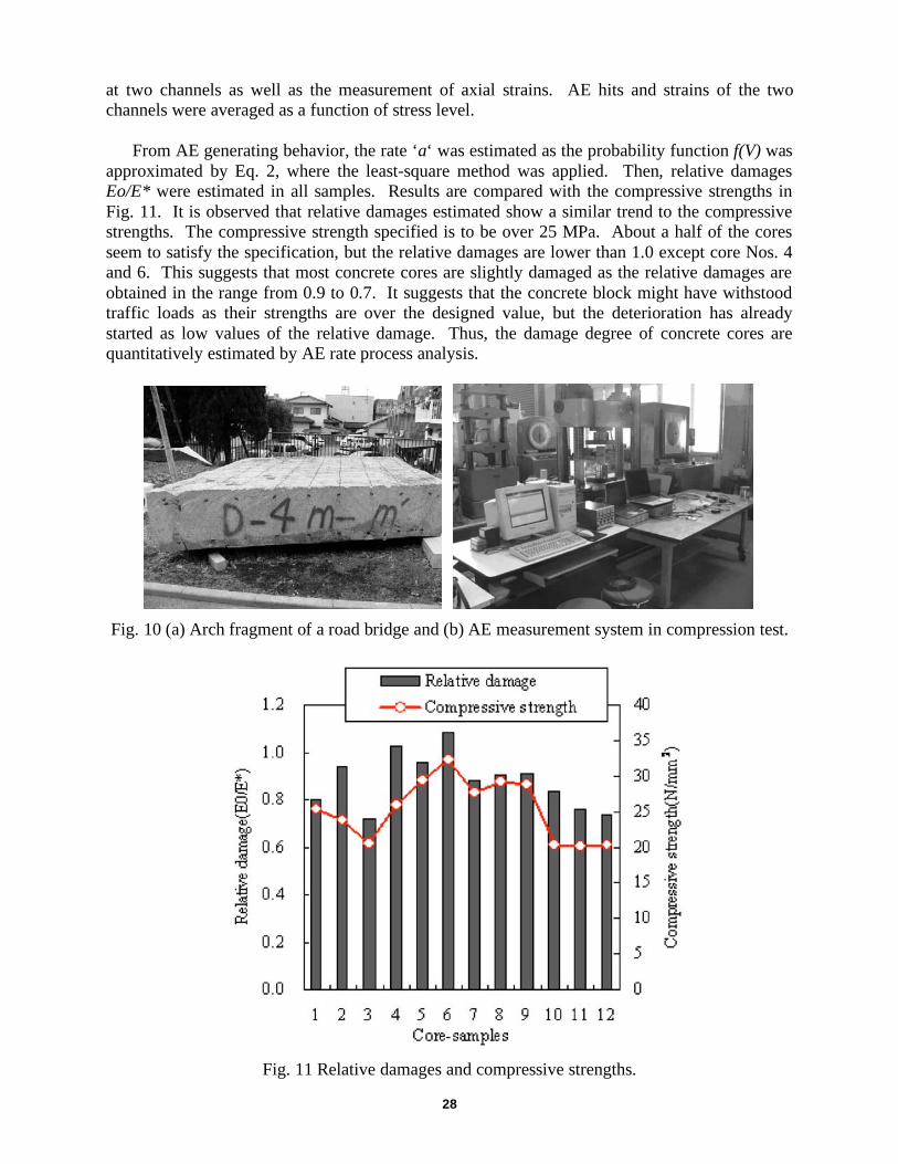
(2) Relative Damage of Concrete in a Road Bridge
Cylindrical samples of 10 cm in diameter were core-drilled from a concrete block (3.0 m 3.0
m 0.68 m), which was taken from an arch fragment of a road bridge shown in Fig. 10(a). The
bridge had been in service for more than 50 years, and was recently replaced because of road
expansion. After core-drilling, 12 cylindrical samples of 20-cm height were made by sawing and
end-polished.
AE measurement in a compression test was conducted as shown in Fig 10(b). Silicone
grease was pasted on the top and the bottom of the sample, and a Teflon sheet was inserted to
reduce AE counts generated due to friction. MISTRAS-AE system (manufactured by PAC) was
employed to count AE hits. AE hits were detected by using an AE sensor (PAC UT-1000 reso-
nance frequency: approx. 1 MHz). The frequency range was from 60 kHz to 1 MHz. For event
counting, the dead time was set to 2 ms. It should be noted that AE measurement was conducted
28
at two channels as well as the measurement of axial strains. AE hits and strains of the two
channels were averaged as a function of stress level.
From AE generating behavior, the rate ‘a‘ was estimated as the probability function f(V) was
approximated by Eq. 2, where the least-square method was applied. Then, relative damages
Eo/E* were estimated in all samples. Results are compared with the compressive strengths in
Fig. 11. It is observed that relative damages estimated show a similar trend to the compressive
strengths. The compressive strength specified is to be over 25 MPa. About a half of the cores
seem to satisfy the specification, but the relative damages are lower than 1.0 except core Nos. 4
and 6. This suggests that most concrete cores are slightly damaged as the relative damages are
obtained in the range from 0.9 to 0.7. It suggests that the concrete block might have withstood
traffic loads as their strengths are over the designed value, but the deterioration has already
started as low values of the relative damage. Thus, the damage degree of concrete cores are
quantitatively estimated by AE rate process analysis.
Fig. 10 (a) Arch fragment of a road bridge and (b) AE measurement system in compression test.
Fig. 11 Relative damages and compressive strengths.
29
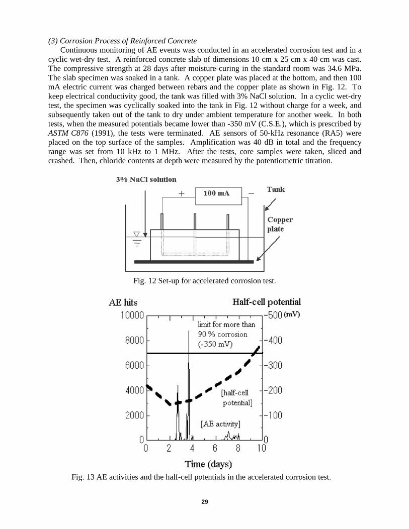
(3) Corrosion Process of Reinforced Concrete
Continuous monitoring of AE events was conducted in an accelerated corrosion test and in a
cyclic wet-dry test. A reinforced concrete slab of dimensions 10 cm x 25 cm x 40 cm was cast.
The compressive strength at 28 days after moisture-curing in the standard room was 34.6 MPa.
The slab specimen was soaked in a tank. A copper plate was placed at the bottom, and then 100
mA electric current was charged between rebars and the copper plate as shown in Fig. 12. To
keep electrical conductivity good, the tank was filled with 3% NaCl solution. In a cyclic wet-dry
test, the specimen was cyclically soaked into the tank in Fig. 12 without charge for a week, and
subsequently taken out of the tank to dry under ambient temperature for another week. In both
tests, when the measured potentials became lower than -350 mV (C.S.E.), which is prescribed by
ASTM C876 (1991), the tests were terminated. AE sensors of 50-kHz resonance (RA5) were
placed on the top surface of the samples. Amplification was 40 dB in total and the frequency
range was set from 10 kHz to 1 MHz. After the tests, core samples were taken, sliced and
crashed. Then, chloride contents at depth were measured by the potentiometric titration.
Fig. 12 Set-up for accelerated corrosion test.
Fig. 13 AE activities and the half-cell potentials in the accelerated corrosion test.

30
A relation between AE activity and half-cell potentials in the accelerated corrosion test is
given in Fig. 13. Two periods of high AE activity (hits) are observed. At the first period, the
half-cell potentials start to decrease, where an abrupt increase in AE hits is observed at around
three days. The potentials reach lower than –350 mV (C.S. E) after the second period. Because
such two periods as the onset of corrosion in reinforcement and the nucleation of cracking in
concrete due to the expansion of corrosion products are defined in the standards, the two high
AE activities are quite suggestive in the deterioration process due to the corrosion of reinforced
concrete.
To classify AE sources (micro-cracks) in the corrosion process, AE parameter analysis was
performed. Variations of RA values and the average frequencies in the cyclic wet-dry test are
given in Fig. 14. Two stages are reasonably identified from the figure. During the first period of
around 40 days elapsed, RA value is high and the average frequency is low. From Fig. 6, this
suggests that shear cracks are actively generated. It is considered that shear cracks occur in re-
inforcement due to the onset of corrosion or rust breakage. During the second period around 100
days elapsed, RA value in Fig. 14 is lower than the first period and the average frequency is
high. This implies the occurrence of tensile cracks. The expansion due to corrosion products
should result in the nucleation of tensile cracks in concrete. Consequently, it is reasonable to
consider that the second high AE activity corresponds to the nucleation of concrete cracking.
Fig. 14 Variations of AE parameters.
Chloride concentrations at the cover-thickness were also investigated to compare with AE
results. It was found that chloride concentrations at reinforcement were higher than 0.3 kg/m3
after the first period and became higher than 1.2 kg/m3 after the second. These results are in good
agreement with the values prescribed as the lower bound and the upper bound for the corrosion
in the specification.
(4) Mechanisms of Corrosion Cracking
A concrete specimen of dimensions 25 cm x 25 cm x 10 cm with a hole of 3-cm diameter
was tested. The hole corresponds to rebar location with 4-cm cover-thickness. The compressive
strength of concrete at 28-day standard curing was 37.9 MPa. The velocity of P wave was 4730
m/s and the modulus of elasticity was 29.7 GPa. P-wave velocity was applied to SiGMA
31
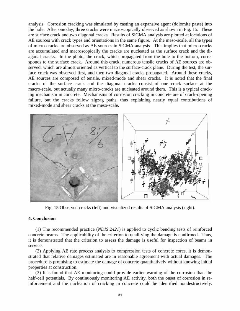
analysis. Corrosion cracking was simulated by casting an expansive agent (dolomite paste) into
the hole. After one day, three cracks were macroscopically observed as shown in Fig. 15. These
are surface crack and two diagonal cracks. Results of SiGMA analysis are plotted at locations of
AE sources with crack types and orientations in the same figure. At the meso-scale, all the types
of micro-cracks are observed as AE sources in SiGMA analysis. This implies that micro-cracks
are accumulated and macroscopically the cracks are nucleated as the surface crack and the di-
agonal cracks. In the photo, the crack, which propagated from the hole to the bottom, corre-
sponds to the surface crack. Around this crack, numerous tensile cracks of AE sources are ob-
served, which are almost oriented as vertical to the surface-crack plane. During the test, the sur-
face crack was observed first, and then two diagonal cracks propagated. Around these cracks,
AE sources are composed of tensile, mixed-mode and shear cracks. It is noted that the final
cracks of the surface crack and the diagonal cracks consist of one crack surface at the
macro-scale, but actually many micro-cracks are nucleated around them. This is a typical crack-
ing mechanism in concrete. Mechanisms of corrosion cracking in concrete are of crack-opening
failure, but the cracks follow zigzag paths, thus explaining nearly equal contributions of
mixed-mode and shear cracks at the meso-scale.
Fig. 15 Observed cracks (left) and visualized results of SiGMA analysis (right).
4. Conclusion
(1) The recommended practice (NDIS 2421) is applied to cyclic bending tests of reinforced
concrete beams. The applicability of the criterion to qualifying the damage is confirmed. Thus,
it is demonstrated that the criterion to assess the damage is useful for inspection of beams in
service.
(2) Applying AE rate process analysis to compression tests of concrete cores, it is demon-
strated that relative damages estimated are in reasonable agreement with actual damages. The
procedure is promising to estimate the damage of concrete quantitatively without knowing initial
properties at construction.
(3) It is found that AE monitoring could provide earlier warning of the corrosion than the
half-cell potentials. By continuously monitoring AE activity, both the onset of corrosion in re-
inforcement and the nucleation of cracking in concrete could be identified nondestructively.

32
This suggests that AE monitoring is practically applicable to in situ monitoring for the corrosion
damage in reinforced concrete structures.
(4) Crack propagation due to corrosion of reinforcement in concrete is studied experimen-
tally. Cracking mechanisms are investigated by SiGMA with 3-D VRML display. The surface
crack and the diagonal cracks are observed at the macro-scale, while many micro-cracks are
identified by SiGMA analysis around them. The results show a promise to apply SiGMA pro-
cedure to investigate micro-scale or meso-scale mechanisms of cracking in concrete.
All results discussed are closely associated with standardization actions in the committee,
RILEM TC212-ACD, for proposing RILEM recommendations.
References
ASTM C876 (1991), Standard Test Method for Half-Cell Potentials of Uncoated Reinforcing
Steel in Concrete, ASTM.
JCMS-III B5706 (2003), Monitoring Method for Active Cracks in Concrete by Acoustic Emis-
sion, Federation of Construction Materials Industries, Japan.
NDIS 2421 (2000), Recommended Practice for In-Situ Monitoring of Concrete Structures by
AE, Japanese Society for Nondestructive Inspection.
Ohtsu, M. (1995),”The History and Development of Acoustic Emission in Concrete Engineer-
ing,” Concrete Library of JSCE, 25, 121-134.
Ohtsu, M. (2000),”Moment Tensor Analysis and SiGMA Code,” Acoustic Emission-Beyond the
Millenium, Elsevier, Amsterdam, pp. 19-34.
Ohtsu, M. and Watanabe, H. (2001),”Quantitative Damage Estimation of Concrete by Acoustic
Emission,” Construction and Building Materials, 15(5-6), 217-224.
Ohtsu, M., Uchida, M., Okamoto, T. and Yuyama, S. (2002),”Damage Assessment of Reinforced
Concrete Beams qualified by AE,” ACI Structural Journal, 99(4), 411-417.
Shigeishi, M. and Ohtsu, M. (2003),”Virtual Reality Presentation of Moment Tensor Analysis by
SiGMA”, J. Korean Society for NDT, 23(3), 189-199.