acme chemicals - eitinsp.comeitinsp.com/home/wp-content/uploads/2019/04/report-horz-ast.pdf · the...
TRANSCRIPT

Report No.: 11090-01
Inspector: Jeff Walling
Employer: Eagle Inspection Technologies
Inspection Date: 10/17/2011
ACME ChemicalsHarrington, DE
Tank 1
API Certification No. 2071
Diesel Fuel (#2 Fuel Oil)
Inspector Signature
IN-SERVICE
Inspection Report For
An STI SP001 inspection was completed on Tank #1 in the ACME Chemicals facility located at Harrington, DE on 10/17/2011. The inspection was conducted in accordance with client criterion for NDE which included visual and UT examinations. The tank was built to UL-142 specification for underground storage tanks for storing fuel oil. This tank is presently being utilized for fuel oil as an aboveground storage tank. The inspection was conducted in accordance with requirements of the Steel Tank Institute SP001 Standard. The following is a detailed report of the inspection including findings and recommendations.

3.0 INSPECTION RESULTS3.1 Foundation3.2 Shell3.3 Appurtenances 3.4 Roof3.5 Floor3.6 Ancillary Equipment3.7 Other
4.0 RECOMMENDATIONS4.1 Foundation4.2 Shell4.3 Appurtenances 4.4 Roof4.5 Floor4.6 Ancillary Equipment4.7 Other4.8 Next Inspections
5.0 ULTRASONIC THICKNESS (UT) MEASUREMENTS5.1 Results Summary 5.2 Recommendations
1.0 EXECUTIVE SUMMARY
2.0 VESSEL DATA
TABLE OF CONTENTS
APPENDIX A
APPENDIX B
APPENDIX C
APPENDIX D
APPENDIX E
APPENDICIES Mechancial Integrity Calculations
Thickness Measurement Record
Inspection Drawings
STI Inspection Checklist
Inspection Photographs
APPENDIX F NDE Records and Certifications
APPENDIX G Supplemental Reference Documents
APPENDIX H CAD Drawing - Saddle Mods
Page 2

1.0 EXECUTIVE SUMMARY
An STI SP001 inspection of Fuel Oil Storage Tank #1 located at the ACME Chemicals site in Harrington, DE was conducted on 10/17/2011. This inspection was conducted to collect data in order to evaluate the mechanical integrity and fitness for continued service of the tank.
The tank is located in an area that does not have secondary containment; however, the secondary containment is scheduled to be installed in the near future. Based on the assumption that the secondary containment will be installedwith in the next year, the tank was evaluated as a Category 1 tank. The tank should be in satisfactory condition after the completion of the recommended repairs for a 20 year inspection interval for Category 1 tanks in accordance withthe STI SP001 Table 5.5.
The tank does not have an emergency relief vent, high level alarm, or high level pump cutoff installed. Recommend these items be installed as soon as possible to comply with the Delaware State Regulations (DNREC Section 3.9, 8, & 11).The supports for this tank do not meet the UL-142 design criteria. Calculations in accordance with the Zick formula results in the tank being stressed at the horn of the saddle (see section 3.2 and 4.2 for more details and recommendations andthe horizontal tank calculations in Appendix A).
The tank heads have a nominal thickness of 0.300" which is below the recommended thickness (of 0.313") in UL-142 for un-braced heads for horizontal tanks larger than 72". The tank heads should be braced in accordance with the UL-142 standard as prescribed in Chapter 13.3 (reference Figure 13.1 and Table 13.2 of UL-142) Please refer to the results and recommendation sections of this report for more detailed information of these and other discrepancies and recommendations that were identified during the course of this inspection.
Next Inspection per SP001 for Category 1 Storage Tanks after recommended repairs are completed: 10/17/2031
Page 3
3.1 Foundation:
3.1.1 The foundation is constructed of three concrete saddles. There is nocontainment area presently installed. A new containment area is schedule to be install within the next year.
3.1.2 The saddle contact with the shell is at 70" width (cord length to theshell cylinder) on a 10ft diameter vessel. This results in a 71º contact angle. Normal minimum contact angles are recommended to be not less than 120º. This condition may be creating undue stress at the horn of the saddle and should be further evaluated by a mechanical engineer experience in storage tank design. (reference UL-142 Table 31.1 and Appendix G for pages from the PV Handbook by Eugene F. Megyesy (pg 84-85) and ASME VIII, Div. 1 App. G (G6) for supporting documentation).
3.2 Shell:
3.2.1 The shell butt welds seams and head lap welds appear to be insatisfactory condition with no preferential corrosion.
3.2.2 External surfaces have complete coating failure and surface oxidation.
3.2.3 The tank heads have a nominal thickness of 0.300" which is below the recommended thickness (of 0.313") in UL-142 for un-braced heads forhorizontal tanks larger than 72".
3.2.3 The supports for this tank do not meet the UL-142 design criteria.Calculations in accordance with the Zick formula results in the tank beingstressed at the horn of the saddle (see attached calculations in Appendix A). Specifications that do not meet UL-142 criteria are as follows:
A. Foundation contact angle is below 120º (ref. Fig 31.1).
B. The distance from the head to the foundation is greater than D/4 (120"/4 = 30") (ref. para. 31.2.5).
C. There are no wear plates installed on the vessel (ref. para 31.2.6 & Table 31.1).
3.3 Appurtenances:
3.3.1 The shell nozzles are in satisfactory mechanical condition.
3.3.2 External surfaces have complete coating failure and surface oxidation.
3.3.3 The 2" normal vent appears to be in satisfactory condition.
3.3.4 There is no emergency vent installed on this tank as required by Delaware State Regulations (DNREC Section 3.9 & 11).
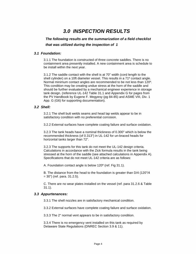
3.0 INSPECTION RESULTS
The following results are the summarization of a field checklist
that was utilized during the inspection of 1
Page 4

3.4 Roof:
3.4.1 N/A
3.5 Floor:
3.5.1 N/A
3.6 Ancillary Equipment:
3.6.1 There are no level gauge systems installed on this tank as requiredby Delaware State Regulations (DNREC Section 8 &11).
3.6.2 There are no level alarms installed on this tank or pump high levelcutoff switch as required by Delaware State Regulations (DNREC Section 8 & 11).
3.6.3 There is no grounding system installed on this tank.
3.7 Other:
3.7.1 The tank does not have ladder access or platforms for safe access to tank top manway or appurtenances.
Accessways
Page 5

4.1 Foundation:
4.1.1 Install the containment area as planned within the next year.
4.1.2 The contact angle created by the concrete saddle (less than 120º)may be creating undue stress at the horn of the saddle and should be further evaluated buy a mechanical engineer experience in horizontal storage tank design or built up to 120º minimum contact angle (where the saddle width in contact with the tank (or cord length) is 104"). (reference UL-142 Table 31.1 and Appendix G of this report for pages from the PV Handbook by Eugene F. Megyesy (pg 84-85) and ASME VIII, Div. 1 App. G (G6) for supporting documentation) (reference Appendix H for CAD Drawings of required Mods).
4.2 Shell:
4.2.1 4.2.1 Clean and coat the tank to restore 100% coverage.
4.2.2 Brace the tank heads in accordance with the UL-142 standard asprescribed in Chapter 13.3 (Figure 13.1 and Table 13.2).
4.2.3 Install support wear plates on shell in accordance with therequirements of UL-142 para 31.2.6 & Table 31.1.
4.2.4 Install stiffening rings on shell at the tank supports (reference Zickpaper for design specifications) to relieve stress at the horn of the saddle.
4.3 Nozzle:
4.3.1 Clean and coat the tank nozzles to restore 100% coverage.
4.3.2 Install an 8" Emergency Vent on this tank in accordance with theMorrison Vent Guide (reference Appendix G) to meet the requirements ofthe Delaware State Regulations (DNREC Section 3.9 & 11).
4.0 RECOMMENDATIONS
4.4 Roof
4.4.1 N/A
4.5 Floor:
4.5.1 N/A
4.6 Ancillary Equipment:
the Delaware State Regulations (DNREC Section 8 & 11).
4.6.2 Install ether a high level alarm system on the tank or pump high levelcutoff switch as required by Delaware State Regulations (DNREC Section 8 &11).
Page 6

4.8 Next Inspections:
4.8.1 Next internal inspection is due by:
10/17/20314.8.3 Next UT inspection is due by:
Shell4.8.4 Governing component limiting life:
4.6.3 Install grounding system on tank.
4.7 Other:
4.7.1 Consider Installing ladders and platforms to accommodate safeaccess to manway and appurtenances on top of tank.
Accessways
10/17/20314.8.2 Next External inspection is due by:
Page 7

5.1 Results Summary:
5.1.1 UT examination of tank components (shell and heads) werecompleted on all accessible surfaces. UT results show minimal wall lossdue to internal corrosion.
5.2 Recommendations:
5.2.1 Re-inspect tank external components in twenty years based on SP001 inspection interval criteria for Category 1 Tanks (this recommendation assumes the containment structure will be in place within the next year to upgrade the tanks to Category 1 status).
5.0 ULTRASONIC THICKNESS (UT) MEASUREMENTS
Page 8

APPENDIX A
1) AST Component RL Calculations
2) Horizontal Vessel Calculations (as is condition)
3) Horizontal Vessel Calculations (to UL-142 Design Specs)
Engineering Calculations
Report No.: 11090-01
Page 9

Minimum Thickness Determinations:
2) Pipe components calculated per ASME B31.3, para. 304 as follows: PD/2(SE+PY) = t
COMPONENT REMAINING LIFE EVALUATIONReport No11090-01
InitialsJLW
Client ACME
Tank NoTank 1
Date 10/17/2011
Temp. °F100
3) PV cyl. components calculated per ASME Sect VIII, UG 27 as follows: PR/SE-0.6P = t
1) Components calculated per original design Ca as follows: tnom - Ca = t
4) Components calculated per original code of construction, (ASME, API, et.)
Component tmin may be determined by any of the following as relative:
HORIZONTAL STORAGE TANK
Component Remaining Life Calculations:
Where:Ca = Remaining corrosion allowance of the component under consideration, in inches.Cr = Corrosion rate of the component under consideration, in inches per year.tact = Minimum thickness measurement of the component under consideration, as recorded at the time of inspection, in inches.tmin = minimum required thickness of component, at the maximum allowable loading , in inches.tprev = previous thickness measurement of the component under consideration, as recorded at last inspection or nominal thickness if no previous thickness measurements, in inches.RL = Estimated remaining life of the component under consideration, in years. Y = Time span between thickness readings or age of the component if nominal thickness is used for tprev, in years.
Size t prev t act t min Ca Cr RLCML Comp. Disc. Age96 0.300 0.289 0.250 0.039 0.00055 71001 Head 1 (East) 2096 0.300 0.303 0.250 0.053 0 >20002 Head 2 (West) 2096 0.300 0.295 0.250 0.045 0.00025 180003 Shell Crs 1 2096 0.300 0.294 0.250 0.044 0.0003 147004 Shell Crs 2 2096 0.300 0.285 0.250 0.035 0.00075 47005 Shell Crs 3 2096 0.300 0.288 0.250 0.038 0.0006 63006 Shell Crs 4 2096 0.300 0.287 0.250 0.037 0.00065 57007 Shell Crs 5 2096 0.300 0.287 0.250 0.037 0.00065 57008 Shell Crs 6 20
11090-01Report No.:
Page 10

(Based on Zick Formula for Two Saddle Tanks)
HORIZONTAL TANK EVALUATION
File No
4
Report No
11090-01
Initials
JLW
Client
ACME Chemicals
Tank No
1
Date 10/17/2011
Temp. °F
100
0.2833wt
Service
Fuel Oil #2
SG
0.88
Material Catagory
CS/Crom. Stl
(PCI)
FH (in.)
114.00
A
57
E
0.70
S
23600
H
2.000
L
207
P
0
D
120.000
Temp.
100
ts
0.300
th
0.300
Y
30000
R
60.000
6
a°
120
29000000
Mtl # in L limit
6632
CuFt in Head
0
Mtl # in Head
855
Total #
79489
Prod # in L limit
70646
Q
39744
b
12.000
tn Head
0.300
tn Shell
0.300
Other Weight, lbs
500
K1
0.335
K8
0.603CS Unknown
MEMaterial
Stress in Saddle (SS+) 840
Stress in Mid Span (SM+) 31
Stress due to Int Press (SP +) 0
=([Q]*[A]*(1-((1-([A]/[L])+(([R]^2-[H]^2)/(2*[A]*[L])))/(1+((4*[H])/(3*[L]))))))/([K1]*[R]^2*[ts])
=(([Q]*[L]/4)*((1+(2*(([R]^2-[H]^2)/[L]^2)))/(1+(4*[H])/(3*[L]))-((4*[A])/[L])))/(3.1416*[R]^2*[ts])
=[P]*[R]/2*[ts]
Sum of Tensional Stress (S1 +): 840
0.05 Vessel Strength is adequate for Tension LoadsRatio ([S1+]/S*E)
LONGITUDINAL BENDING STRESS
Allowable Compressive Stress 1: -8333 =([ME]/29)*(([ts]/[R])*(2-((2/3)*100*([ts]/[R]))))
0.005 Check Compression StressRatio = [ts]/[R] > 0.005
Allowable Compressive Stress 2: -15000 =[Y]/2
Vessel Strength is adequate for Compressive loads
STRESS IN TENSION
STRESS IN COMPRESSION
Stress in Saddle (SS - ) 467
Stress in Mid Span (SM - ) 31
=([Q]*[A]*(1-((1-([A]/[L])+(([R]^2-[H]^2)/(2*[A]*[L])))/(1+((4*[H])/(3*[L]))))))/([K8]*[R]^2*[ts])
=(([Q]*[L]/4)*((1+(2*(([R]^2-[H]^2)/[L]^2)))/(1+(4*[H])/(3*[L]))-((4*[A])/[L])))/(3.1416*[R]^2*[ts])
Sum of Compress. Stress (S1 - ): -467
=SP+S
=SP-SS
16520Max Allow.
-8333Max Allow.
0.06Ratio ([S1-]/Mx Alw)
23600 120
Head Type
Flat
1
Stiffening Rings? No
Page 11

(Based on Zick Formula for Two Saddle Tanks)
HORIZONTAL TANK EVALUATION
File No
4
Report No
11090-01
Initials
JLW
Client
ACME Chemicals
Tank No
1
Date 10/17/2011
Temp. °F
100
0.2833wt
Service
Fuel Oil #2
SG
0.88
Material Catagory
CS/Crom. Stl
(PCI)
FH (in.)
114.00
Stress in Shell (SS) 1147
Stress in Head (SH) Not Required
Stress due to Int Press (SP). 0
([K4]*[Q])/([R]*[th])
=[P]*[R]/2*[th]
Sum of Stress in Head: (SH3) NA =([K5]*[Q]/[R]*[th])+[SP]
0.05 Vessel Strength is adequate for tangential shear stress (<0.80*S)Ratio
TANGENTIAL SHEAR STRESS
1.17
Stiffening ring at horn of saddle?
K2
=(([K2]*[Q])/([R]*[ts]))*(([L]-(2*[A]))/([L]+(4/3*[H])))
NA
NARatio NA
NA NAWear Plate?
0.30
ts
1) Stress Value (S) was determined from API-653 for unknown carbon steel materials.2) Tank contact angle is at 71º. Tank was assessed for 120º contact angle (lowest setting in program) at the nominal thickness of 0.300 inches.3) Stress at the horn of the saddle exceeds the allowable stress for this tank assuming a 120º contact angle (and therefore would be even more stressed at71º).
NoNo
Stress in Horn of Saddle (S4) -82420
Stress at Wear Plt Edge (S4)
=-([K7]*[Q])/([ts]*([b]+1.56*([R]*[ts])^0.5))
3.49 Exceeds allowable circumferential stress at saddle horn (1.50*S)Ratio
CIRCUMFERENTIAL STRESS
0.053
= -([Q]/(4*[ts]*([b]+1.56*([R]*[ts])^0.5)))-((12*[K6]*[Q]*[R])/([L]*[ts2]))
0.76
Ratio NA
NA0.30
tsK6 K7
Stress in Bottom of Shell (S5) -5408
NA NA
Wear Plate Values
0.18Ratio Vessel strength is adequate for stress in shell bottom (<.50*Y)
= -([Q]/(4*[ts]*([b]+1.56*([R]*[ts])^0.5)))-((12*[K6]*[Q]*[R])/([L]*[ts]^2))
NOTES:
Tangential Shear Stress (S2) 1147
0.090ts2
[ts]^2
Stiffening Ring(s) No
Page 12

(Based on Zick Formula for Two Saddle Tanks)
HORIZONTAL TANK EVALUATION
File No
4
Report No
11090-01
Initials
JLW
Client
ACME Chemicals
Tank No
1
Date 10/17/2011
Temp. °F
100
0.2833wt
Service
Fuel Oil #2
SG
0.88
Material Catagory
CS/Crom. Stl
(PCI)
FH (in.)
114.00
Variable = DefinitionA = distance from tangent line of the head to center of saddle, in.a° = horn of saddle contact angle, degreesb = width of saddle, in.D = outside diameter of vessel, in.E = joint efficiencyFH = fill height, in.H = outside depth of dish of head, in.K = constant from tableL = length of vessel tan-tan, in.M = materialME = modulus if elasticity, psiP = vessel maximum allowable working pressure, psiPCI = pounds per cu. in.PSI = pounds per sq. in.Q = load on one saddleR = outside radius of component, in.S = allowable stress value, psiSG = specific gravityth = actual thickness of head, in.tn = nominal thickness, in.ts = actual thickness of shell, in.Wpa° = wear plate contact angle, degreesWPL = wear plate length beyond horn of saddle, in.WPt = wear plate thickness, in.WPw = wear plate width, in.wt = weight, lbsY = yield stress of material, psi.
DEFINITIONS, Calculations based on L.P. Zicks analysis presentation in 1951
Page 13

(Based on Zick Formula for Two Saddle Tanks)
HORIZONTAL TANK EVALUATION
File No
4
Report No
11090-01
Initials
JLW
Client
ACME Chemicals
Tank No
1
Date 10/17/2011
Temp. °F
100
0.2833wt
Service
Fuel Oil #2
SG
0.88
Material Catagory
CS/Crom. Stl
(PCI)
FH (in.)
114.00
A
30
E
0.70
S
23600
H
2.000
L
354
P
0
D
120.000
Temp.
100
ts
0.240
th
0.240
Y
30000
R
60.000
6
a°
120
29000000
Mtl # in L limit
11342
CuFt in Head
0
Mtl # in Head
855
Total #
134368
Prod # in L limit
120816
Q
67184
b
12.000
tn Head
0.300
tn Shell
0.300
Other Weight, lbs
500
K1
0.335
K8
0.603CS Unknown
MEMaterial
Stress in Saddle (SS+) -532
Stress in Mid Span (SM+) 1556
Stress due to Int Press (SP +) 0
=([Q]*[A]*(1-((1-([A]/[L])+(([R]^2-[H]^2)/(2*[A]*[L])))/(1+((4*[H])/(3*[L]))))))/([K1]*[R]^2*[ts])
=(([Q]*[L]/4)*((1+(2*(([R]^2-[H]^2)/[L]^2)))/(1+(4*[H])/(3*[L]))-((4*[A])/[L])))/(3.1416*[R]^2*[ts])
=[P]*[R]/2*[ts]
Sum of Tensional Stress (S1 +): 1556
0.09 Vessel Strength is adequate for Tension LoadsRatio ([S1+]/S*E)
LONGITUDINAL BENDING STRESS
Allowable Compressive Stress 1: -6933 =([ME]/29)*(([ts]/[R])*(2-((2/3)*100*([ts]/[R]))))
0.004 Check Compression StressRatio = [ts]/[R] > 0.005
Allowable Compressive Stress 2: -15000 =[Y]/2
Vessel Strength is adequate for Compressive loads
STRESS IN TENSION
STRESS IN COMPRESSION
Stress in Saddle (SS - ) -296
Stress in Mid Span (SM - ) 1556
=([Q]*[A]*(1-((1-([A]/[L])+(([R]^2-[H]^2)/(2*[A]*[L])))/(1+((4*[H])/(3*[L]))))))/([K8]*[R]^2*[ts])
=(([Q]*[L]/4)*((1+(2*(([R]^2-[H]^2)/[L]^2)))/(1+(4*[H])/(3*[L]))-((4*[A])/[L])))/(3.1416*[R]^2*[ts])
Sum of Compress. Stress (S1 - ): -1556
=SP+SM
=SP-SM
16520Max Allow.
-6933Max Allow.
0.22Ratio ([S1-]/Mx Alw)
23600 120
Head Type
Flat
1
Stiffening Rings? No
Page 14

(Based on Zick Formula for Two Saddle Tanks)
HORIZONTAL TANK EVALUATION
File No
4
Report No
11090-01
Initials
JLW
Client
ACME Chemicals
Tank No
1
Date 10/17/2011
Temp. °F
100
0.2833wt
Service
Fuel Oil #2
SG
0.88
Material Catagory
CS/Crom. Stl
(PCI)
FH (in.)
114.00
Stress in Shell (SS) 2206
Stress in Head (SH) Not Required
Stress due to Int Press (SP). 0
([K4]*[Q])/([R]*[th])
=[P]*[R]/2*[th]
Sum of Stress in Head: (SH3) NA =([K5]*[Q]/[R]*[th])+[SP]
0.09 Vessel Strength is adequate for tangential shear stress (<0.80*S)Ratio
TANGENTIAL SHEAR STRESS
1.17
Stiffening ring at horn of saddle?
K2
=(([K2]*[Q])/([R]*[ts]))*(([L]-(2*[A]))/([L]+(4/3*[H])))
NA
NARatio NA
0.25
WPt
6
WPLWear Plate?
0.49
ts
1) Stress Value (S) was determined from API-653 for unknown carbon steel materials.2) This evaluation shows the tank in an acceptable condition if it were to meet the UL-142 designed specifications.(i.e. two saddles 30" from tank ends, with 120º contact angle and a wear plate installed (meeting the minimum required dimensions)
YesNo
Stress in Horn of Saddle (S4) -16466
Stress at Wear Plt Edge (S4) -29309
=-([K7]*[Q])/([ts]*([b]+1.56*([R]*[ts])^0.5))
0.70 Vessel strength is adequate for stress at the saddle horn (<1.50*S)Ratio
CIRCUMFERENTIAL STRESS
0.013
= -([Q]/(4*[ts]*([b]+1.56*([R]*[ts])^0.5)))-((12*[K6]*[Q]*[R])/([L]*[ts2]))
0.76
1.24Ratio Vessel strength is adequate for stress at wear plt edge (<1.50*S)
26.5
WPw0.49
tsK6 K7
Stress in Bottom of Shell (S5) -5093
131
a°
0.011
K6
Wear Plate Values
0.17Ratio Vessel strength is adequate for stress in shell bottom (<.50*Y)
= -([Q]/(4*[ts]*([b]+1.56*([R]*[ts])^0.5)))-((12*[K6]*[Q]*[R])/([L]*[ts]^2))
NOTES:
Tangential Shear Stress (S2) 2206
0.120ts2
[WPt]^2+[ts]^2
Stiffening Ring(s) No
Page 15
APPENDIX B
1) Component UT Measurements
Thickness Measurement Record
Report No.: 11090-01
Page 16

AST Component Inspection Data
Component Thickness Measurements (in inches)
API-653 STORAGE TANK EVALUATION
Report No11090-01
InspectorJeff Walling
ClientACME Chemicals
Vessel1
Date10/17/2011
Location tml-1 tml-2 tml-3 tml-4 MinimumComponent tml-5CML tml-6East Head 0.289 0.306 0.289 0.302 0.289 Head 0.290001
West Head 0.303 0.307 0.304 0.305 0.303 Head 0.300002
Q1-4 0.295 0.300 0.304 0.302 0.295Shell Crs 1003
Q1-4 0.294 0.300 0.299 0.302 0.294Shell Crs 2004
Q1-4 0.285 0.293 0.292 0.296 0.285Shell Crs 3005
Q1-4 0.289 0.293 0.288 0.292 0.288Shell Crs 4006
Q1-4 0.287 0.293 0.288 0.292 0.287Shell Crs 5007
Q1-4 0.290 0.292 0.287 0.293 0.287Shell Crs 6008
Report No.: 11090-01
Page 17

APPENDIX C
1) Shell Layout Drawings
Inspection Drawings
Report No.: 11090-01
Page 18

Page 19

APPENDIX DSTI Inspection Checklist
Report No.: 11090-01
Page 20

Company: ACME Chemicals Tank: 1 Report No.: 11090-01 Date: 10/17/2011
Inspector: Jeff WallingCert No.: 30388
API-653 AST INSPECTION CHECKLIST(S)
STEEL TANK INSTITUTE SP001 INSPECTION CHECKLIST
TANK CONFIGURATION: TANK HAS CRDM? AST CATEGORY
AST in contact with ground no 2 or 3
Elevated tank with spill control and with no part of AST in contact with ground Yes 1
Vertical tank with RPB and spill control NA 1
Vertical tank with double bottom and spill control NA 1
Vertical tank with RPB under tank and spill control NA 1
Double-wall AST No 1
AST with secondary containment dike/berm No 1
Review prior formal and periodic inspections, repair and alteration data before each inspection.
1 FOUNDATION
a.___Visually inspect for pitting, and corrosion.b.___Check foundation bolts are secure and have minimum thread engagement. c.___Check for coating failured.___Check attachment welds for cracking and corrosion.
1.1 Concrete Foundation Support
a._X_Inspect for broken concrete, spalling and cracks. especially under bearing surfaces.b._X_Inspect for erosion under foundation.c._X_Check for settlement around perimeter of tank.
1.2 Wooden Saddle Support
a.___Inspect for splintered, broken, flattened, dry rotted and cracked membranes, surfaces, especially under bearing surfaces.b.___Inspect for cavities under foundation and vegetation against bottom of tank.c.___Check for settlement around perimeter of tank.
1.3 Containment (in the process of installing new containment area)
a.___Inspect the area for buildup of trash, vegetation and obstructions.b.___Inspect sump drain operation.c.___Check that runoff rainwater drains away from the tank.d.___Describe type of construction - Earthen, Concrete, Asphalt, Gravele.___Inspect condition of containment.
2 SHELLS
Page 1 of 5
Page 21

Company: ACME Chemicals Tank: 1 Report No.: 11090-01 Date: 10/17/2011
Inspector: Jeff WallingCert No.: 30388
API-653 AST INSPECTION CHECKLIST(S)
2.1 External Visual Inspection
a._X_Visually inspect shell surface for paint failures, pitting, corrosion, denting, out-of-round and part deformation.b.___Clean angle support rings and inspect for corrosion and thinning on plate, annular space and welds.c._X_Inspect the shell-to-foundation seal or barrier.d.___Check for broken, unused insulation rod supports causing corrosion nodes.e._X_Visually inspect weld joints for cracking, pitting, corrosion and signs of leaking. (product residue).f.___Perform dye penetrant or magnetic particle tests if leaks or cracks are suspected.g._X_Check for proper grounding
2.2 Internal Visual Inspection
a.___Check atmospheric conditions, fill out and post safe entry permit form.b.___Appropriate and wear required PPE for safe entry.c.___Inspect shell surfaces for coating failures, pitting and corrosion.d.___Inspect baffle plate surfaces and weld attachments for cracking, pitting, and corrosion. Check bolts are secure and have minimum thread engagement.e.___Inspect agitator shaft and blade surfaces for cracking, pitting, corrosion. Check bolts are secure and have minimum thread engagement.f.___Inspect heating coils surfaces and weld attachments, for cracking, pitting, corrosion. Check bolts are secure and have minimum thread engagement.g.___Inspect pressure containing weld joints for cracking, pitting, and corrosion. h.___Perform dye penetrant or magnetic particle tests if cracks are suspected.i.___Perform MFE Scan or UTT alternative scan of bottom plates or plates in contact with the earth.J.___ Perform Vacuum Box exam of floor lap welds.K.___Perform VT inspection of bottom and shell plates using flashlight held parallel with floor.L.___Perform VT inspection of roof underside plates using flashlight.M.___Check tank shell for out-of-round and plumb conditions.
3 SHELL APPURTENANCES
3.1 Manways and Nozzles
a._X_Inspect for cracks or signs of leakage on weld joints at nozzles, manways, and reinforcing plates.B._X_Inspect for shell plate dimpling around nozzles, caused by excessive pipe deflection.c.___Inspect for flange leaks and leaks around bolting.d.___Check flange bolts are secure and have minimum thread engagement. e.___Inspect sealing of insulation around manways and nozzles.f.___Check for inadequate manway flange and cover thickness on mixer manways.g.___Check exposed flange and cover faces.
3.2 PV Vents
a.___Inspect for flange leaks and leaks around bolting.b.___Check flange bolts are secure and have minimum thread engagement. c._X_Record inlet and outlet sizes sizes. Inlet ___2"_______ Outlet____2"_____d._X_Check that relief system outlet discharges to safe location (outside of building).e.___Record certification date ___Open Vent_____f.___Record pressure settings PR_NA____ VAC__NA___g.___Record type and ID number. ____NA______
B.3.3 Shell-Mounted Sample Station
a.___Inspect sample lines for function of valves and plugging of lines, including drain or return-to-tank line.b.___Check circulation pump for leaks and operating problems.c.___Test bracing and supports of sample system and equipment.
Page 2 of 5
Page 22
Company: ACME Chemicals. Tank: 1 Report No.: 11090-01 Date: 10/17/2011
Inspector: Jeff WallingCert No.: 30388
API-653 AST INSPECTION CHECKLIST(S)
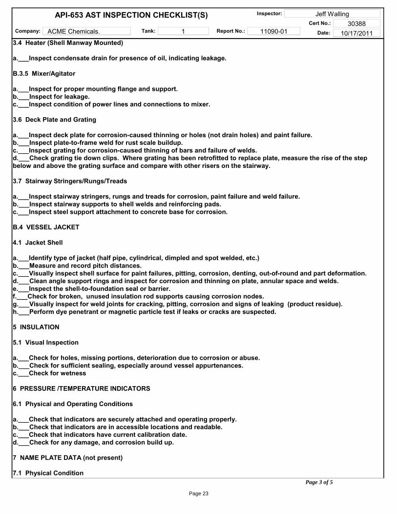
3.4 Heater (Shell Manway Mounted)
a.___Inspect condensate drain for presence of oil, indicating leakage.
B.3.5 Mixer/Agitator
a.___Inspect for proper mounting flange and support.b.___Inspect for leakage.c.___Inspect condition of power lines and connections to mixer.
3.6 Deck Plate and Grating
a.___Inspect deck plate for corrosion-caused thinning or holes (not drain holes) and paint failure.b.___Inspect plate-to-frame weld for rust scale buildup.c.___Inspect grating for corrosion-caused thinning of bars and failure of welds.d.___Check grating tie down clips. Where grating has been retrofitted to replace plate, measure the rise of the step below and above the grating surface and compare with other risers on the stairway.
3.7 Stairway Stringers/Rungs/Treads
a.___Inspect stairway stringers, rungs and treads for corrosion, paint failure and weld failure.b.___Inspect stairway supports to shell welds and reinforcing pads.c.___Inspect steel support attachment to concrete base for corrosion.
B.4 VESSEL JACKET
4.1 Jacket Shell
a.___Identify type of jacket (half pipe, cylindrical, dimpled and spot welded, etc.)b.___Measure and record pitch distances.c.___Visually inspect shell surface for paint failures, pitting, corrosion, denting, out-of-round and part deformation.d.___Clean angle support rings and inspect for corrosion and thinning on plate, annular space and welds.e.___Inspect the shell-to-foundation seal or barrier.f.___Check for broken, unused insulation rod supports causing corrosion nodes.g.___Visually inspect for weld joints for cracking, pitting, corrosion and signs of leaking (product residue).h.___Perform dye penetrant or magnetic particle test if leaks or cracks are suspected.
5 INSULATION
5.1 Visual Inspection
a.___Check for holes, missing portions, deterioration due to corrosion or abuse.b.___Check for sufficient sealing, especially around vessel appurtenances.c.___Check for wetness
6 PRESSURE /TEMPERATURE INDICATORS
6.1 Physical and Operating Conditions
a.___Check that indicators are securely attached and operating properly.b.___Check that indicators are in accessible locations and readable.c.___Check that indicators have current calibration date.d.___Check for any damage, and corrosion build up.
7 NAME PLATE DATA (not present)
7.1 Physical ConditionPage 3 of 5
Page 23

Company: ACME Chemicals Tank: 1 Report No.: 11090-01 Date: 10/17/2011
Inspector: Jeff WallingCert No.: 30388
API-653 AST INSPECTION CHECKLIST(S)
a.___Check that name plate is securely attachedb.___Check that name plate is in accessible location and readable.
7.2 Record Following Name Plate Data
a.___Design Code:________b.___Year Built:______c.___Shop Built YES / NOd.___MAP____________e.___Nominal Diameter_________f.___Nominal Shell Thickness_______g.___Nominal Head/Roof Thickness_______h.___Nominal Height_____i.___Head Material______j.___Shell Material________k.___Jacket Material_________l.___Manufacturer_____m.___Year Built_____
8 VESSEL LAYOUT DRAWINGS
8.1 Record Following Data
a._X_Roof or Head and skirt lengths and type (especially head to shell joint config.)b._X_Shell lines of support (Head Tangents, Braces, Jacket Closures, etc.).c._X_Foundation support member dimensions and orientation.d._X_Inside/Outside diameter.e._X_Tank component nominal thicknesses.f._X_Nozzle layouts, size and use.
9 UT THICKNESS READINGS
9.1 Measure and Record Vessel Part Thicknesses
a._X_Roof/Heads - (4) locations minimum, (1) in each quadrant and for roofs - an X pattern (6) per leg.b._X_Shell - (12) locations, (3) in each quadrant for each course.c.___Jacket - As required (at least (4) locations).d.___Nozzles - (4) locations, (1) in each quadrant for 2 inches and greater, (1) location for nozzles less than 2 inches.E.___Floor - If ultrasonic testing equipment that is capable of scanning the tank (i.e MFE) is not practical, use equipment that tests individual points. In this case, take UTT measurements of at least 15 points per each 12 inches x 12 inches (0.3 meters x 0.3 meters) square area of the shell that is in contact with the ground.
Page 4 of 5
Page 24

APPENDIX EInspection Photographs
Report No.: 11090-01
Page 25

ACME CHEMICALS - TANK #1 REPORT –11090-01 INSPECTION PHOTOGRAPHS
Fuel Oil Tank #1
Top Side with complete coating failure and surface oxidation throughout.
Page 26

ACME CHEMICALS - TANK #1 REPORT –11090-01 INSPECTION PHOTOGRAPHS
4” Plug on top of tank
2” Vent piping
Page 27

ACME CHEMICALS - TANK #1 REPORT –11090-01 INSPECTION PHOTOGRAPHS
Tank concrete saddle with rubber insert for corrosion protection
Page 28

APPENDIX F
1) UT Calabration Report
2) NDE Tech Certification
3) API Inspector Certification
4) STI Inspector Certification
NDE Records and Certifications
Report No.: 11090-01
Page 29

ULTRASONIC EXAMINATION REPORT
CLIENT: ACME Chemicals CLIENT PO #: 10002-001 REPORT NO.: 11090-01 EIT JOB #: 11090 EQUIP ID: Tank 1 SERVICE: #2 Fuel Oil JOB DESCR.: Horizontal AST thickness readings. EXAM DATE: 07/16/2010 PROCEDURE #: EIT-UTT-01 SPECIFICATION: API-653 / UL-142 MATERIAL: CS
TEST PARAMETERS
UT UNIT Unit: Panameterics DL37+ S/N: 5904 Cal Date: 11/11/09
PROBE SPECIFICATIONS Long Frq 5 mHZ Size: .375 Type: D790 S/N 905216 SW Frq: mHZ Size: Type: S/NSW Frq: mHZ Size: Type: S/NSW Frq: mHZ Size: Type: S/N
COUPLANT MFG: Ultra Grade Gel-40 Surface Cond: Coated
CALIBRATION STANDARD Type: Raycheck 6 Step Block S/N: 00-7235
Calibration Reference Level (db) 0: 51 45: 60: 70:
Other: 0: 45: 60: 70:Start Time: 0800 End Time: 1200 Start Time: End Time:
Results/Comments: Reference API-653 Report
UT Level II Technician: Jeff Walling
Page 30


Page 32

CERTIFICATIO,N
STEEL TANK INSTITUTE certifies that
Jeff Walling
has successfully completed the sTI sP001 Adjunct Certification for API 653 Inspectors.
This certification is dependant on an active API 653 certification.
Expiration Date: October 18, 2017 ID#: AC 35012
~~na C.~ Dana Schmidt, P.E. Project Engineer Steel Tank Institute
(Si'Fn Steel
~ ." ~~IInTank r::~~'\'~~ nInstitute
. " , ~ c t ~//
~~:"Ot:.II":'('O~
Page 33

APPENDIX G
1) Morrison Venting Guide References
2) PV Handbook, Horizontal Tank Design
3) ASME VIII, Div 1 - Appendix G (Design of Supports)
Supplemental Reference Documents
Report No.: 11090-02
Page 34

Page 5Morrison Bros. Co. 800•553•4840
���������� �����������
�������������
TANK WETTED REQ'D VENT EMERGENCY
CAPACITY DIAMETER LENGTH AREA CAPACITY VENT SIZE
(Gallons) (Ft or In) (Ft-In) (Sq Ft) (CFH) (Inches)
280 36" 5'-2" 47 49,520 3
300 38" 5'-0" 49 51,640 3
500 48" 5'-5" 69 72,650 4
530 46" 6'-0" 71 74,750 4
550 48" 6'-0" 75 78,950 4
1,000 48" 10'-8" 119 124,950 6
1,000 64" 6'-0" 109 114,450 4
1,500 64" 9'-0" 147 154,350 6
2,000 64" 12'-0" 184 193,200 6
2,500 64" 15'-0" 222 223,320 6
3,000 64" 18'-0" 259 243,680 6
3,000 6'-0" 14'-0" 240 233,400 6
4,000 64" 24'-0" 335 281,100 6H
4,000 6'-0" 19'-0" 311 270,060 6H
5,000 8'-0" 13'-4" 326 276,960 6H
6,000 8'-0" 16'-0" 376 300,480 8
8,000 8'-0" 21'-4" 477 344,340 8
10,000 8'-0" 27'-0" 584 385,920 8
10,000 9'-0" 21'-0" 540 369,200 8
10,000 10'-0" 17'-0" 518 360,840 8
10,000 10'-6" 15'-7" 515 359,700 8
12,000 8'-0" 32'-0" 678 420,080 8
12,000 9'-0" 25'-0" 625 401,000 8
12,000 10'-0" 20'-6" 600 392,000 8
12,000 11'-0" 17'-0" 583 385,540 8
15,000 8'-0" 40'-0" 829 470,990 8FL
15,000 10'-6" 23'-5" 703 429,020 8
20,000 10'-0" 34'-2" 922 499,820 8FL
20,000 10'-6" 31'-0" 896 491,760 8FL
20,000 11'-0" 28'-0" 868 483,080 8FL
25,000 10'-6" 38'-6" 1,082 537,530 10
30,000 10'-6" 46'-3" 1,274 568,100 10
Page 35

Page 8 Morrison Bros. Co. 800•553•4840
TABLE 1
SI Units: 1 Ft = 0.30 m; 1 sq ft = 0.09 sq mSource for Chart: NFPA 30, 1996 Edition, Table B-1
���������� �����������
����������������������
(Wetted Area Equals 75 Percent Total Area)
Tank Diameter
3 Ft 4 Ft 5 Ft 6 Ft 7 Ft 8 Ft 9 Ft 10 Ft 11 Ft 12 Ft Tank Diameter
3 Ft 4 Ft 5 Ft 6 Ft 7 Ft 8 Ft 9 Ft 10 Ft 11 Ft 12 Ft
3 Ft 32 38 Ft 685 791 902 1013 1129 1244
4 Ft 39 55 39 Ft 701 810 923 1036 1155 1272
5 Ft 46 65 88 40 Ft 718 828 944 1060 1181 1301
6 Ft 53 74 100 128 41 Ft 734 847 966 1083 1207 1329
7 Ft 60 84 112 142 173 42 Ft 751 866 987 1107 1233 1357
8 Ft 67 93 124 156 190 226 43 Ft 767 885 1008 1130 1259 1385
9 Ft 74 102 136 170 206 245 286 44 Ft 904 1029 1154 1284 1414
10 Ft 81 112 147 184 223 264 308 353 45 Ft 923 1051 1178 1310 1442
11 Ft 88 121 159 198 239 283 329 377 428 46 Ft 941 1072 1201 1336 1470
12 Ft 95 131 171 213 256 301 350 400 454 509 47 Ft 960 1093 1225 1362 1498
13 Ft 102 140 183 227 272 320 371 424 480 537 48 Ft 979 1114 1248 1388 1527
14 Ft 109 150 194 241 289 339 393 447 506 565 49 Ft 998 1135 1272 1414 1555
15 Ft 116 159 206 255 305 358 414 471 532 594 50 Ft 1157 1295 1440 1583
16 Ft 123 169 218 269 322 377 435 495 558 622 51 Ft 1178 1319 1466 1612
17 Ft 130 178 230 283 338 395 456 518 584 650 52 Ft 1199 1342 1492 1640
18 Ft 137 188 242 298 355 414 477 542 610 678 53 Ft 1220 1366 1518 1668
19 Ft 197 253 312 371 433 499 565 636 707 54 Ft 1246 1389 1544 1696
20 Ft 206 265 326 388 452 520 589 662 735 55 Ft 1263 1413 1570 1725
21 Ft 216 277 340 404 471 541 612 688 763 56 Ft 1437 1593 1753
22 Ft 225 289 354 421 490 562 636 714 792 57 Ft 1460 1622 1781
23 Ft 235 300 368 437 508 584 659 740 820 58 Ft 1484 1648 1809
24 Ft 244 312 383 454 527 605 683 765 848 59 Ft 1507 1674 1839
25 Ft 324 397 470 546 626 706 791 876 60 Ft 1531 1700 1866
26 Ft 336 411 487 565 647 730 817 905 61 Ft 1726 1894
27 Ft 347 425 503 584 668 754 843 933 62 Ft 1752 1923
28 Ft 359 440 520 603 690 777 869 961 63 Ft 1778 1951
29 Ft 371 454 536 621 711 801 895 989 64 Ft 1803 1979
30 Ft 383 468 553 640 732 824 921 1018 65 Ft 1829 2007
31 Ft 395 482 569 659 753 848 947 1046 66 Ft 1855 2036
32 Ft 496 586 678 775 871 973 1074 67 Ft 2064
33 Ft 510 602 697 796 895 999 1103 68 Ft 2092
34 Ft 524 619 715 817 918 1025 1131 69 Ft 2120
35 Ft 539 635 734 838 942 1051 1159 70 Ft 2149
36 Ft 553 652 753 860 966 1077 1187 71 Ft 2177
37 Ft 567 668 772 881 989 1103 1216 72 Ft 2205
Approximate Wetted Area of Tanks With Flat Heads, Square Feet
TankLength
Approximate Wetted Area of Tanks With Flat Heads, Square Feet
TankLength
Page 36

Page 10 Morrison Bros. Co. 800•553•4840
• At 14.7 psis and 60° F (101.4 kPa and 16° C)
• Interpolate for intermediate values.
• These values taken from NFPA 30.
• These pipe sizes apply only to open vent pipes to the specified diameter not more than12 inches (0.3m) long and a pressure in tank of not more than 2.5 psig (17.1 kPa).
• If tank is to be equipped with a venting device or flame arrestor, the vent opening is toaccommodate the venting device or flame arrestor in accordance with the listed CFH.
NORMAL VENTING RECOMMENDATIONS
NFPA 30 — 1996
2-3.5.2 Normal vents shall be sized to be at least as large as thefilling or withdrawal connection, whichever is larger, but in no caseless than 1-1/4 in. (3 cm) nominal inside diameter.
������� ��������������
20 21,100 230 31,600 240 42,100 350 52,700 360 63,200 370 73,700 480 84,200 490 94,800 4100 105,000 4120 126,000 5140 147,000 5160 168,000 5180 190,000 5200 211,000 6250 239,000 6300 265,000 6350 288,000 8400 312,000 8500 354,000 8600 392,000 8700 428,000 8800 462,000 8900 493,000 8
1000 524,000 101200 557,000 101400 587,000 101600 614,000 101800 639,000 102000 662,000 102400 704,000 102800
and over742,000 10
Wetted Surface
(Sq Ft.)
Venting Capacity
(CFH)
Minimal OpeningNominal Pipe Size
(Inches)
Page 37

Page 11Morrison Bros. Co. 800•553•4840
!�������� �����"�����#�$����%
summer U.S. Gallons Diameter U.S. Gallons Diameter U.S. Gallons(Inches) Per Ft Length (Inches) Per Ft Length (Inches) Per Ft Length
24 23.50 65 172.38 106 458.3025 25.50 66 177.72 107 467.7026 27.58 67 183.15 108 475.8927 29.74 68 188.66 109 485.0028 31.99 69 194.25 110 493.7029 34.31 70 199.92 111 502.7030 36.72 71 205.67 112 511.9031 39.21 72 211.51 113 521.4032 41.78 73 217.42 114 530.2433 44.43 74 223.42 115 540.0034 47.16 75 229.50 116 549.5035 49.98 76 235.66 117 558.5136 52.88 77 241.90 118 568.0037 55.86 78 248.23 119 577.8038 58.92 79 254.63 120 587.5239 62.06 80 261.12 121 597.7040 65.28 81 267.69 122 607.2741 68.58 82 274.34 123 617.2642 71.97 83 281.07 124 627.0043 75.44 84 287.88 125 638.2044 78.99 85 294.78 126 647.7445 82.62 86 301.76 127 658.6046 86.33 87 308.81 128 668.4747 90.13 88 315.95 129 678.9548 94.00 89 323.18 130 690.3049 97.96 90 330.48 131 700.1750 102.00 91 337.86 132 710.9051 106.12 92 345.33 133 721.7152 110.32 93 352.88 134 732.6053 114.61 94 360.51 135 743.5854 118.97 95 368.22 136 754.6455 123.42 96 376.01 137 765.7856 127.95 97 383.89 138 776.9957 132.56 98 391.84 139 788.3058 137.25 99 399.88 140 799.6859 142.02 100 408.00 141 811.1460 146.88 101 416.00 142 822.6961 151.82 102 424.48 143 834.3262 156.83 103 433.10 144 846.0363 161.93 104 441.8064 167.12 105 449.82
Page 38

Page 12 Morrison Bros. Co. 800•553•4840
����������
��&'(��)*�)���������
S IZ E F IG. N O. D E S CR IP T IONP R E S S U R E
o z/s q in.CA P A CIT Y
CF HD A T A S OU R CE
2" 148ALT P res s ure Vacuum Vent 8 14,200 T es ted at Iowa S tate Univ. by P . Kavanagh, 1960
2" 148ALT P res s ure Vacuum Vent 16 10,500 T es ted at Iowa S tate Univ. by P . Kavanagh, 1960
2" 351S F lame Arres ter 22,000 T es ted at Ohio S tate Univ. by O. E . B uxton Jr. 1967
2" 351S /548-748 F lame Arres ter/Vent 2 15,500 B as ed on IS U T es t of 2" 351S /548-748 - 8 oz by Kavanagh, 1990
2" 351S /548-748 F lame Arres ter/Vent 4 15,500 B as ed on IS U T es t of 2" 351S /548-748 - 8 oz by Kavanagh, 1990
2" 351S /548-748 F lame Arres ter/Vent 6 15,500 B as ed on IS U T es t of 2" 351S /548-748 - 8 oz by Kavanagh, 1990
2" 351S /548-748 F lame Arres ter/Vent 8 15,500 T es ted at Iowa S tate Univ. by P . Kavanagh, 1990
2" 351S /548-748 F lame Arres ter/Vent 12 13,000 B as ed on IS U T es t of 2" 351S /548-748 - 16 oz by Kavanagh, 1990
2" 351S /548-748 F lame Arres ter/Vent 16 13,000 T es ted at Iowa S tate Univ. by P . Kavanagh, 1990
2" 354 Updraft Vent 27,650 T es ted at Univ. Wis cons in P latteville by L. Lee, 1988
3" 354 Updraft Vent 59,000 T es ted at Univ. Wis cons in P latteville by L. Lee, 1996
4" 354 Updraft Vent 116,900 T es ted at Continental Dis c Corp, 1997
2" 548-748 P res s ure Vacuum Vent 2 20,200 B as ed on IS U T es t of 2" 548 - 8 oz by Kavanagh, 1960
2" 548-748 P res s ure Vacuum Vent 4 20,200 B as ed on IS U T es t of 2" 548 - 8 oz by Kavanagh, 1960
2" 548-748 P res s ure Vacuum Vent 6 20,200 B as ed on IS U T es t of 2" 548 - 8 oz by Kavanagh, 1960
2" 548-748 P res s ure Vacuum Vent 8 20,200 T es ted at Iowa S tate Univ. by P . Kavanagh, 1960
2" 548-748 P res s ure Vacuum Vent 12 18,600 Approx. Calculated C.F .H.
2" 548-748 P res s ure Vacuum Vent 16 18,000 T es ted at Iowa S tate Univ. by P . Kavanagh, 1960
2" 749 P res s ure Vacuum Vent 8 8,500 T es ted at Univ. Wis cons in P latteville by L. Lee, 1988
2" 749 P res s ure Vacuum Vent 12 8,500 T es ted at Univ. Wis cons in P latteville by L. Lee, 1988
2" 749 CR B P res s ure Vacuum Vent 1.70 11,000 T es ted at Univ. Wis cons in P latteville by L. Lee, 1996
3" 548 P res s ure Vacuum Vent 2 43,000 B as ed on IS U T es t of 3" 548 - 8 oz by Kavanagh, 1990
3" 548 P res s ure Vacuum Vent 4 43,000 B as ed on IS U T es t of 3" 548 - 8 oz by Kavanagh, 1990
3' 548 P res s ure Vacuum Vent 6 43,000 B as ed on IS U T es t of 3" 548 - 8 oz by Kavanagh, 1990
3" 548 P res s ure Vacuum Vent 8 43,000 T es ted at Iowa S tate Univers ity by P . Kavanagh, 1990
3" 548 P res s ure Vacuum Vent 12 40,000 B as ed on IS U T es t of 3" 548 - 16 oz by P . Kavanagh, 1990
3" 548 P res s ure Vacuum Vent 16 40,000 T es ted at Iowa S tate Univers ity by P . Kavanagh, 1990
3" 244 S eries E mergency Vent 8 59,900 T es ted at Continental Dis c Corp, 1997
4" 244 S eries E mergency Vent 8 119,750 B as ed on Continental Dis c Corp T es t of 4" 16 oz 244, 1997
4" 244 S eries E mergency Vent 12 119,750 B as ed on Continental Dis c Corp T es t of 4" 16 oz 244, 1997
4" 244 S eries E mergency Vent 16 119,750 T es ted at Continental Dis c Corp, 1997
6" 143 P res s ure Vacuum Vent 8 246,130 B as ed on Continental Dis c Corp T es t of 6" 16 oz 244, 1997
6" 143 P res s ure Vacuum Vent 10 246,130 B as ed on Continental Dis c Corp T es t of 6" 16 oz 244, 1997
6" 143 P res s ure Vacuum Vent 16 246,130 B as ed on Continental Dis c Corp T es t of 6" 16 oz 244, 1997
6" 244 S eries E mergency Vent 8 246,130 B as ed on Continental Dis c Corp T es t of 6" 16 oz 244, 1997
6" 244 S eries E mergency Vent 10 246,130 B as ed on Continental Dis c Corp T es t of 6" 16 oz 244, 1997
6" 244 S eries E mergency Vent 16 246,130 T es ted at Continental Dis c Corp, 1997
6" 244H S eries E mergency Vent 8 298,750 B as ed on Continental Dis c Corp T es t of 6" 16 oz 244, 1997
8" 143 P res s ure Vacuum Vent 8 462,000 B as ed on UL Calc from Cont. Dis c Corp. T es t of 244 S eries , 1997
8" 143 P res s ure Vacuum Vent 16 462,000 B as ed on UL Calc from Cont. Dis c Corp. T es t of 244 S eries , 1997
8" 143A F lngd P res s ure Vacuum Vent 8 509,550 B as ed on UL Calc from Cont. Dis c Corp. T es t of 244 S eries , 1997
8" 143A F lngd P res s ure Vacuum Vent 16 509,550 B as ed on UL Calc from Cont. Dis c Corp. T es t of 244 S eries , 1997
8" 244M Male Emergency Vent 8 453,300 UL Calc bas ed on Continental Dis c Corp. T es t of 244 S eries , 1997
8" 244M Male Emergency Vent 16 453,300 UL Calc bas ed on Continental Dis c Corp. T es t of 244 S eries , 1997
8" 244 F emale E mergency Vent 8 462,000 UL Calc bas ed on Continental Dis c Corp. T es t of 244 S eries , 1997
8" 244 F emale E mergency Vent 16 462,000 UL Calc bas ed on Continental Dis c Corp. T es t of 244 S eries , 1997
8" 244F F langed Emergency Vent 8 509,550 UL Calc bas ed on Continental Dis c Corp. T es t of 244 S eries , 1997
8" 244F F langed Emergency Vent 16 509,550 UL Calc bas ed on Continental Dis c Corp. T es t of 244 S eries , 1997
10" 143A F lngd P res s ure Vacuum Vent 2.5 808,350 B as ed on UL Calc from Cont. Dis c Corp. T es t of 244 S eries , 1997
10" 143A F lngd P res s ure Vacuum Vent 8 808,350 B as ed on UL Calc from Cont. Dis c Corp. T es t of 244 S eries , 1997
10" 143A F lngd P res s ure Vacuum Vent 16 808,350 B as ed on UL Calc from Cont. Dis c Corp. T es t of 244 S eries , 1997
10" 244F S eries F langed Emergency Vent 2.5 808,350 UL Calc bas ed on Continental Dis c Corp. T es t of 244 S eries , 1997
10" 244F S eries F langed Emergency Vent 8 808,350 UL Calc bas ed on Continental Dis c Corp. T es t of 244 S eries , 1997
10" 244F S eries F langed Emergency Vent 16 808,350 UL Calc bas ed on Continental Dis c Corp. T es t of 244 S eries , 1997
2" 922 Vent/Overfill Alarm 8 24,656 T es ted at Continental Dis c Corp, 1997
Page 39

Page 13Morrison Bros. Co. 800•553•4840
��������+�������
MORRISON VENTS CFH
1. 2" Fig. 548 - 4 oz P ............................ 20,2004" Fig. 244 - 8 oz P ........................ 119,750
139,950
2. 2" Fig. 548 - 8 oz P ............................ 20,2006" Fig. 244 - 16 oz P ...................... 246,130
266,330
3. 2" Fig. 548 - 8 oz P ............................ 20,2008" Fig. 244 - 16 oz P ...................... 462,000
482,200
4. 2" Fig. 548 - 8 oz P ............................ 20,20010" Fig. 244 - 16 oz P ...................... 808,350
828,550
5. 2" Fig. 548 - 8 oz P ............................ 20,20010" Fig. 244F - 8 oz P ...................... 808,350
828,550
6. 2" Fig. 548 - 8 oz P ............................ 20,20010" Fig. 244F - 2.5 oz P ................... 808,350
828,550
7. 2" Fig. 548 - 8 oz P ............................ 20,2002" Fig. 922 - 8 oz P .......................... 24,656
44,856
MORRISON VENTS CFH
8. 3" Fig. 548 - 4 oz P ............................ 43,0004" Fig. 244 - 8 oz P ........................ 119,750
162,750
9. 3" Fig. 548 - 8 oz P ............................ 43,0006" Fig. 244 - 16 oz P ...................... 246,130
289,130
10. 3" Fig. 548 - 8 oz P ............................ 43,0008" Fig. 244 - 16 oz P ...................... 462,000
505,000
11. 3" Fig. 548 - 8 oz P ............................ 43,00010" Fig. 244F - 16 oz P .................... 808,350
851,350
12. 3" Fig. 548 - 8 oz P ............................ 43,00010" Fig. 244F - 8 oz P ...................... 808,350
851,350
13. 3" Fig. 548 - 8 oz P ............................ 43,00010" Fig. 244F - 2.5 oz P ................... 808,350
851,350
14. 3" Fig. 548 - 8 oz P ............................ 43,0002" Fig. 922 - 8 oz P .......................... 24,656
67,650
Page 40

Page 14 Morrison Bros. Co. 800•553•4840
Emergency Vents
244
Emergency VentEmergency vent (pressure reliefonly) used on abovegroundstorage tanks, as a code require-ment that helps prevent the tanksfrom becoming over-pressurizedand rupturing if exposed to fire.UL listed.
DescriptionThe 244 emergency vent consists of a body and cover thatmoves up and down on a center pin. Pressure inside thetank forces the cover to lift up off the vent seat, allowingair to exhaust. The center pin guides the movement. Whenpressure falls the cover lowers back down onto seat andthe vent is automatically reset.
Code ComplianceWhen properly sized for the tank, this vent will conform tothe requirements of NFPA 30, 30A, UL 142, UL 2244, API2000, and PEI RP200.
The 244 emergency vent must be properly sized andselected for each specific tank application in order to
meet the proper “venting capacity” requirements.
WARNING!The 244 emergency vent is for “emergency pressure
relief only” and must be used in conjunction witha “normal vent” or pressure vacuum vent such
as a Morrison Fig. 354, 548, 748, or 749.
WARNING!
Material and Configuration Options1. Aluminum Body or Iron Body…suffix (I) indicates iron.
2. Metal-to-Metal Seat (brass) or Soft Seat (Viton®)…suffix(O) indicates o-ring.
3. Male Threads/Female Threads/Flanged MountingConnection…suffix (M) indicates male, and suffix (F)indicates flanged.
4. Opening Pressure Setting…settings indicated areapproximate.
Emergency vent should be set higher than thenormal vent so the normal vent operates first.
Aluminum Body Style…(O) indicates Viton® o-ring seatOpeningPressure Ship Venting Mounting
Fig. No. Size Setting Weight Capacity Connection(oz/sq in) (lbs) (CFH)
(@ 2.5 PSI)244 &244O 4" 8.0 10.65 119,750 Female NPT
12.0 16.00 119,750 Female NPT16.0 21.00 119,750 Female NPT
6" 8.0 15.50 246,130 Female NPT10.0 21.50 246,130 Female NPT16.0 33.15 246,130 Female NPT
8" 8.0 34.70 462,000 Female NPT16.0 68.00 462,000 Female NPT
244&244OF 8" 8.0 387.50 509,550 Flanged
16.0 71.50 509,550 Flanged10" 2.5 32.00 808,350 Flanged
8.0 71.00 808,350 Flanged16.0 125.00 808,350 Flanged
244M & (3" OM only)244OM 3" 8.0 5.75 59,900 Male NPT
4" 8.0 11.55 119,750 Male NPT12.0 16.30 119,750 Male NPT16.0 21.25 119,750 Male NPT
6" 8.0 19.45 246,130 Male NPT10.0 24.00 246,130 Male NPT16.0 35.00 246,130 Male NPT
8" 8.0 34.00 453,300 Male NPT16.0 68.00 453,300 Male NPT
244OH 6" 8.0 21.50 298,750 Female NPT16.0 41.40 298,750 Female NPT
244OMH 6" 8.0 23.00 298,750 Male NPT16.0 42.9 298,750 Male NPT
Iron Body Style…(O) indicates Viton® o-ring seatOpeningPressure Ship Venting Mounting
Fig. No. Size Setting Weight Capacity Connection(oz/sq in) (lbs) (CFH)
(@ 2.5 PSI)244I &244OI 4" 8.0 13.65 119,750 Female NPT
12.0 19.00 119,750 Female NPT16.0 24.00 119,750 Female NPT
6" 8.0 20.63 246,130 Female NPT10.0 26.63 246,130 Female NPT16.0 38.28 246,130 Female NPT
8" 8.0 44.33 462,000 Female NPT16.0 77.63 462,000 Female NPT
244MI & (3" OMI only)244OMI 3" 8.0 8.00 59,900 Male NPT
4" 8.0 16.36 119,750 Male NPT12.0 21.11 119,750 Male NPT16.0 26.06 119,750 Male NPT
6" 8.0 27.76 246,130 Male NPT10.0 32.31 246,130 Male NPT16.0 43.31 246,130 Male NPT
8" 8.0 34.63 453,300 Male NPT16.0 75.36 453,300 Male NPT
Fig.244 Fig.244F
Use 16 oz. o-ring to comply with pressure decay test.Contact factory for assistance.
5. Screened Opening…(all 4" and 6", and 8" femalethreaded body only) specify "WITH SCREEN", #3 meshstainless steel screen used for theft control. Screen isNOT intended to function as a flame arrester.
Fig.244M
Page 41

Page 42

Page 43

Page 44

APPENDIX HCAD Drawing - Saddle Mods
Report No.: 11090-01
Page 45

Page 46