aci structural journal ' technical - un mundo de ... estructural/a181sj_111… · aci member...
TRANSCRIPT

dieting.gineer,
,nnance6-1913.:haviour:, 2005,
's, Steelstruction9.:n Guidestitute of
,Ie BodyGeneva,
)lement to)()7.
: Code of;nstitution,
Ig-Part 4:,Sheeting,"
'or Students2007.Structures:Bridge and
f Floors forSCl), Ascot,
,n by Dance4, pp. 37 -44.i.4," Hibbitt
IS of a Long-asurements,"
onse of Steel. Proceedings
:k CompositeQueensland
ystem-Floor,td., Brisbane,)md Testing ofV. 68, No. 15,
,ribrating Floortion,V. 8, 2001,
,ants on Modalr, V. 80, No.5,
ACI STRUCTURAL JOURNAL ' TECHNICAL PAPER. ,
Compression Splices in High-Strength Concrete of 100 MPa(14,500 psi) and Lessby Sung-Chul Chun, Sung-Ho Lee, and Sohwan Oh
In high-strength concrete, a compression lap splice may becalculated to be longer than a tension lap splice according toACI318-08. An experimental study of 72 specimens was conductedon compressive lap splices using concrete compressive strengthsof 80 and 100 MPa (11,600 and 14,500 psi), and the effects ofconcrete strength, splice length, and transverse reinforcement wereassessed. From the regression analyses of 94 tests that failed insplitting, including the data in the literature, two equations weredeveloped with JIJdb and l,Idb to predict the splice strength. Usinga 5%fractile coefficient, (WO design equations for the splice lengthwere derived. The proposed equations provide shorter lengths thanthe splice length in tension, as given by ACI 318-08. In addition,there is no significant difference between the lengths calculated bythe two equations. Therefore, a simple equation with the term off/'.1f: is practically useful within the tested ranges.
Keywords: bond; compression lap splice; end bearing; splice length;splice strength.
INTRODUCTIONThe ACI 318-081 lap requirements for compression splices
do not explicitly account for the effects of the compressivestrength of concrete and transverse reinforcement. Becauseof the end bearing, the splice length in compressioncan be shorter than the length in tension to develop thespecified yield strength of the reinforcing bars. Accordingto ACI 318-08,1 however, the required splice length incompression can exceed the required length in tension asthe concrete strength becomes higher.2.3 This occurs becausethe provisions for compression splices do not properlyconsider the effects of the transverse reinforcement and thecompressive strength of the concrete. Therefore, new criteriafor compression lap splices are required. In the case of aconcrete strength of 60 MPa (8700 psi) and less, a designequation of a compression splice length was proposed byChun et a1.2,3
In this study, compression splices with concrete compres-sive strengths of 80 and 100 MPa (11,600 and 14,500 psi)were tested, which were higher than the maximum strengthsused in previous tests,2'5 Tw.oIIlod~ls.\'Iert: derj"e.d t~ pI:e<iic.~the splice strength and were compared.
RESEARCH SIGNIFICANCESeventy-two columns were tested for developing the design
equations for the compression lap splices with concretestrengths of 80 and 100 MPa (11,600 and 14,500 psi). Halfof the columns had transverse reinforcement. Two models topredict the splice strength were developed from the 94 tests,including the data2,3 of specimens with concrete strengthsof 40 and 60 MPa (5800 and 8700 psi), respectively, throughregression analyses; one was based on the square root ofl/db and the other was based on the simple linear form of
l/db. The equation with the term of l/db was found to bepractically useful within the tested ranges.
EXPERIMENTAL PROGRAMSpecimen variables
The clear spacing between spliced bars from 1.5db to3.0db was not found to affect the splice strength accordingto previous studies2,3,6; therefore, four parameters wereselected: splice length, the compressive strength of theconcrete, the existence of transverse reinforcement, and thebar diameter. To evaluate the effects of these parameters onthe splice strengths, column specimens with lapped splices.were concentrically loaded in a manner similar to that usedin previous tests.2.5
Two bar diameters-22 and 29 mm (No.7 [denotedas D22 specimens hereafter] and No. 9 [denoted asD29 specimens hereafter]), respectively-were chosen,considering the capacities of the loading facilities of10,000 kN (2250 kips) and the continuity of the authors'previous tests.2,3 The design yield strength of the reinforcingbars was 420 MPa (60,000 psi); their measured yieldstrengths, tensile strengths, and moduli of elasticity aresummarized in Table 1. Unfortunately, due to a mistake inordering the reinforcing bars, the measured yield strength ofthe reinforcing bars used in the C 100D22 series was lowerthan the design yield strength.
The test groups were basically classified into unconfinedspecimens and confined specimens. Unconfined specimens
Yield TensileSpecimen Bar diameter, strength, strength, Modulus of elasticity,
series mm (in.) MPa(psi) MPa (psi) MPa(ksi)
C80D22 22 467.6 603.2 183,258series . (0.875) (67,800) (87,500) (26,600)
C80D29 29 491.6 622.1 192,084series (1.128) (71,300) (90,200) (27,900)
.CiOOD2T' 22 386.0 572.4 186,40:j - -- -series (0.875) (56,000) (83,000) (27,000)
CIOOD29 29 458.5 603.9 190,526series (1.128) (66,500) (87,600) (27,600)
ACl Structural Journal, V. 108, No.6, November-December 2011.MS No. S·2010·206.RI received November 6, 2010, and reviewed under Institute
publication policies. Copyright © 2011, American Concrete Institute. All rightsreserved, including the making of copies unless perntission is obtained from thecopyright proprietors. Pertinent discussion including author's closure, if any, will bepublished in the September-October 2012 ACl Structural Journal if the discussion isreceived by May I, 2012.
ACI member Sung-Chul Chun is a Full-Time Lecturer of Architectural Engineering atMokpo National University, Jeonnam, South Korea. H~ received his BS, MS, and PhDfrom Seoul National University, Seoul, South Korea, in 1994, 1996, and 2007, respec-tively. He is a member of Joint ACI-ASCE Committees 352, Joints and Connectionsin Monolithic Concrete Structures; and 408, Developmenr and Splicing of DeformedBars. His research interests include steel anchorage to concrete, composite structures,and the rehabilitation of reinforced concrete structures.
Sung-Ho Lee is a Senior Researcher at DIeT, Suwon, South Korea. He received hisBS and MS from Korea University, Seoul, South Korea, in 2000 and 2002, respectively.His research interests include steel anchorage 10 concrete and the behavior of beam-column joints.
ACI member Bohwan Oh is a Research Fellow at DICT He received his BSfrom Yonsei University, Seoul, South Korea, and his MS and PhD from LehighUniversity, Bethlehem, PA. He is a member of Joint ACI·ASCE Committee 352,Joints and Connections in Monolithic Concrete Structures. His research interestsinclude modeling of concrete behavior and high-rise building systems.
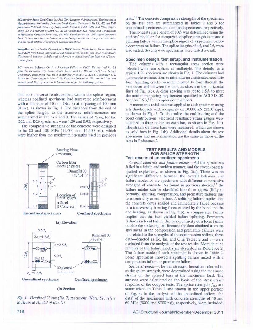
had no transverse reinforcement within the splice region,whereas confined specimens had transverse reinforcementwith a diameter of 10 mm (No.3) at a spacing of 100 mm(4 in.), as shown in Fig. 1. The distances from the end ofthe splice lengths to the transverse reinforcements aresummarized in Tables 2 and 3. The values of Krr/db for theD22 and D29 specimens were 1.29 and 0.98, respectively.
The compressive strengths of the concrete were designedto be 80 and 100 MPa (11,600 and 14,500 psi), whichwere higher than the maximum strengths used in previous
Bearing Plates/(f=20mm)
Carbon fibersheets (2 plies)
IOmm@IOO(#3@4P
)
Lociltion ofstram gages• Steelo Concrete Pointl
IOmm@IOO(#3@4P
)
Expectedfailure line
1.-,
!-icso=1.5db
Unconfined specimens
Fig. I-Details of22 mm (No.7) specimens. (Note: 513 refersto strain at Point 3 of Bar 1.)
tests.2-5 The concrete compressive strengths of the specimenson the test date are summarized in Tables 2 and 3 forunconfined specimens and confined specimens, respectively.
The longest splice length of 10db was determined using theauthors' models2,3 for compression splice strength to ensure asplitting failure within the splice region of a specimen beforea compression failure. The splice lengths of 4db and 7db werealso tested. Seventy-two specimens were tested overall.
Specimen design, test setup, and instrumentationTied columns with a rectangular cross section were
selected with four splices at midheight. The details for atypical D22 specimen are shown in Fig. 1. The columns hadsymmetric cross sections to minimize an unintended eccentricload. Splitting cracks were anticipated to form through theside cover and between the bars, as shown in the horizontallines of Fig. l(b). A clear spacing was set to 1.5db to meetthe minimum spacing requirement specified in ACI 318-08,Section 7.6.3,1 for compression members.
A monotonic axial load was applied to each specimen usinga hydraulic jack with a capacity of 10,000 kN (2250 kips),as shown in Fig. 2. To determine the end bearing and thebond contributions, electrical resistance strain gauges wereattached to three points on each bar, as shown in Fig. l(a).The strains on three bars were measured, which are shownas solid bars in Fig. l(b). Additional details about the testspecimens and instrumentation are the same as those of thetests in Reference 2.
TEST RESULTS AND MODELSFOR SPLICE STRENGTH
Test results of unconfined specimensOverall behavior and failure modes-All the specimens
failed in a brittle and sudden manner, and the cover concretespalled explosively, as shown in Fig. 3(a). There was nosignificant difference between the overall behavior andfailure modes of the specimens with different compressivestrengths of concrete. As found in previous studies,2,3 thefailure modes can be classified into three types: (fully orpartially) splitting, compression, and premature failures dueto eccentricity or end failure. A splitting failure implies thatthe concrete cover spalled and immediately failed becauseof a transversely bursting force exerted by the bond and theend bearing, as shown in Fig. 3(b). A compression failureimplies that the bars yielded before splitting. Prematurefailure is a local failure due to eccentricity or a local failureoutside the splice region. Because the data obtained from thespecimens in the compression and premature failures werenot related to the strengths of the compression splices, thesedata-denoted as Ec, En, and C in Tables 2 and 3-wereexcluded from the analysis of the test results. More detailedfeatures of the failure modes are described in Reference 2.The fail~re mode of each specimeii-Ts' shown in 'Table 2.Some specimens showed a splitting failure mixed with acompression failure or premature failure.
Splice strength-The bar stresses, hereafter referred toas the splice strength, were determined using the measuredstrains on the spliced bars at the maximum load. Thestresses were calculated on the basis of the stress-strainresponse of the coupon tests. The splice strengths fsc.e aresummarized in Table 2 and shown in the upper portionof Fig. 4. In the analysis of the unconfined splices, thedata2 of the specimens with concrete strengths of 40 and60 MPa (5800 and 8700 psi), respectively, were included.

mens3 forively.Lgthemreaeforewere
tionwerefor ashad~ntrich the:antalmeet8-08,
usingkips),d thewerelea).
howne test)f the
mensLcreteis no. and~ssive,3 thelyors dues that::auseld theiilurelatureliluremthewerethese-weretailedLce2,)le 2.'ith a
ed tosured
The;train',e areIrtioni, the) andIlded.
Specimen 10' lJdb sJdb fe', MPa (ksi) Failure modet P" kN (kips) fsc.e> MPa (ksi) fb,.,,, MPa (ksi) /b." MPa(ksi)
C80D22-L4 83.4 (12.1) FS 3657 (822) 420 (60.9) 215 (31.1) 205 (29.7)
C80D22-L4-1 84.5 (12.3) FS 3546 (797) 296 (42.9) 136 (19.7) 160 (23.2)4 7.1
C80D22-L4-2 79.9 (11.6) FS 3470 (780) 346 (50.1) 134 (22.0) 211 (30.6)
C80D22-L4-3 80.7 (11.7) PS + Ec 3413 (767) 338 (49.0) NA NA
C80D22-L7 83.5 (12.1) PS 3993 (898) 444 (64.4) 167 (24.2) 268 (38.9)
C80D22-L7 -I 85, I (12.3) PS + Ec 3767 (847) 411 (59.6) 137 (19,9) 274 (39.7)7 5.6
C80D22-L7-2 79.4 (11.5) PS 3773 (848) 359 (52.0) 152 (22.0) 207 (30.0)
C80D22-L7-3 80.0 (11.6) PS 3273 (736) 438 (63.5) 117 (16.9) 321 (46.6)
C80D22-LlO 84.5 (12.3) PS 3833 (862) 453 (65.7) 178 (25.8) 275 (39.9)
C80D22-Ll 0-1 84.4 (12.2) FS 4063 (913) 440 (63.8) 135 (19,6) 305 (44.2)10 4.1
C80D22-LlO-2 79.6 (11.5) FS+C 3877 (872) 468 (67.8)1 186 (27.0) 281 (40.8)
C80D22-LlO-3 80.3 (11.6) FS 3693 (830) 442(64.1) 113 (16.4) 329 (47.7)
C80D29-L4 86.5 (12.5) FS 5770 (1297) 363 (52.6) 155 (22.4) 208 (30.2)
C80D29-L4-1 88.8 (12.9) FS 5684 (1278) 334 (48.4) 168 (24.3) 166 (24.1)4 7.0
C80D29-L4-2 82.0 (11.9) FS . 5747 (1292) 340 (49.3) 61 (8.9) 278 (40.4)
C80D29-L4-3 81.8 (11.9) FS 5740 (1290) 355 (51.4) 172 (24,9) 183 (26.5)
C80D29-L7 86.2 (12.5) FS 6370 (J432) 422 (61.2) 153 (22.1) 270 (39.1)
C80D29- L7-1 88.8 (12.9) FS 7075 (1591) 492 (71.3) 163 (23.6) 329 (47,7)7 5,5
C80D29-L7-2 81.2 (11.8) PS + Ec 5437 (1222) 406 (58.4) 179 (26.0) 226 (32.8)
C80D29-L7-3 81.5 (11.8) FS 6093 (1370) 403 (58.4) 172 (24.9) 231 (33.5)
C80D29-LlO 89.1 (12.9) PS 5704 (1282) 391 (56.6) 112 (16.2) 279 (40.5)
C80D29-Ll 0-1 86.5 (12.5) FS 6917 (1555) 492 (71.3)1 175 (25.4) 317 (45.9)10 4.0
C80D29-LlO-2 81.3 (11.8) FS 5393 (1212) 431 (62.5) 108 (15.7) 323 (46.8)
C80D29-LlO-3 82,0 (11.9) FS 6293 (1415) 492 (71.3)1 165 (23.9) 327 (47.4)
CIOOD22-L4 101.9 (14.8) FS+Ec 3805 (855) 368 (62.5) 166 (24.0) 202 (29.3)4 7,1
Cl00D22-L4-1 102.3 (14.8) FS +C 4157 (935) 386 (56.W 159 (23.1) 227 (32.9)
CI00D22-L7 101.2 (14.7) C 4409 (991) 386 (56.W 196 (28.4) 190 (27.6)7 5.6
CIOOD22-L7-1 102.0 (14.8) C 4247 (955) 386 (56.0)1 153 (22.2)I
233 (33.8)
CIOOD22-LlO 101.6 (14.7) C 4563 (1026) 386 (56.0)1 140 (20.2) 246 (35.7)10 4.1
CIOOD22-LlO-l 102.0 (14.8) C 4502 (1012) 386 (56.W 150 (21.8) 236 (34,2)
Cl00D29-L4 100.2 (14.5) FS 7340 (1650) 452 (65,5) 186 (27.0) 266 (38.5)4 7.0
CIOOD29-L4-1 101.1 (14.7) FS 7116 (1600) 444 (64.5) 173 (25.1) 271 (39.4)
C100D29-L7 100.2 (14.5) C 7538 (1695) 458 (66.5)1 186 (27.0) 272 (39.5)7 5.5
Cl00D29-L7-1 100.7 (14.6) C 7124 (1602) 458 (66.5)1 185 (26.9) 273 (39.6)
CIOOD29-LlO 100.6 (14.6) C 7106 (1598) 458 (66.5)1 164 (23.8) 295 (42.7)10 4.0
CI00D29-LlO-l 99.4 (14.4) C 7594 (1707) 458 (66,5)1 174 (25.3) 284 (41.2)
'C ID2-L3-4: I is design compres~ive £trel1gth,()!.concrete in MPa; 2 is b~r. ,liameter in. f(lm; 3 is splice length normalized by bar diameter; and 4 of" 1~2, 3" indicatesduplicate specimen.tFS is fully splitting failure; PS is partially splitting failure; C is compression failure; and Ec is premature failure due to eccentricity.ISplice strengths reached yield strengths of spliced bars.Note: NA is not available.
To compensate for the difference in the concrete strengths,the splice strengths were normalized by -V!/. Figure 4shows that the splice strength increased as the splicelength became longer.
The compression lap splice transferred a force by acombination of the bond and the end bearing. The barstresses developed by the end bearing!brg,e and the bondAeare summarized in Table 2 and were also calculated from
the measured strains. In the lower portion of Fig. 4, the barstresses developed by the end bearing are shown for varioussplice lengths. The bar stresses normalized by -V!c' werefound to be nearly constant, irrespective of the change in thesplice length. The mean value of the stresses developed bythe end bearing was 16.5-V!c'MPa (199-V!c' psi).
The bar stresses developed by the bond were obtainedby deducting the stresses developed by the end bearing

Specimen ill' ljdb s,Jdb s/db !/,MPa (ksi) Failure model P,,!eN (kips) f,c." MPa (ksi) !b"." MPa (ksi) lb.•. MPa (ksi)
C80D22-L4-HW 85.2 (12.4) PS 3813 (857) 391 (56.7) 144 (20.9) 247 (35.8)
C80D22-L4-HW-I 84.9 (12.3) PS 3903 (877) 396 (57.4) 159 (23.1) 237 (34.3)4 2.5 2.0
C80D22-L4-HW-2 79.0 (11.5) FS 3607 (811) 408 (59.2) 114 (16.5) 294 (42.7)
C80D22-L4-HW-3 80.6 (11.7) FS 3583 (806) 407 (59.0) 131 (19.0) 276 (40.0)
C80D22-L7-HW 83.2 (12.1) PS 3970 (893) 468 (67.8)1 143 (20.7) 325 (47.1)
C80D22-L7-HW-I 85.0 (12.3) FS +C 4220 (949) 378 (54.8) 118 (17.2) 259 (37.6)7 1.0 3.5
C80D22-L7-HW-2 79.9 (11.6) FS 3723 (837) 458 (66.4) 129 (18.8) 328 (47.6)
C80D22-L7-HW-3 80.9 (11.7) Ec 3560 (800) 396 (57.4) 124 (18.0) 272 (39.4)
C80D22-L 1O-HW 83.2 (12.1) C 4010 (902) 457 (66.3) 149 (21.6) 308 (44.7)
C80D22-LlO-HW-l 84.0 (12.2) C 4120 (926) 468 (67.8)1 160 (23.2) 307 (44.6)10 4.1 0.5
C80D22-LlO-HW-2 80.1 (11.6) Ec 3386 (761) 430 (62.3) 92 (13.4) 337 (48.9)
C80D22-LlO-HW-3 79.3 (11.5) C 3847 (865) 468 (67.8)1 112 (16.2) 356 (51.6)
C80D29-L4-HW 88.4 (12.8) FS 6977 (1569) 436 (63.3) 165 (23.9) 271 (39.3)
C80D29-L4-HW-1 86.0 (12.5) PS+En 5650 (1270) 443 (64.2) 184 (26.7) 258 (37.5)4 3.2 0.3
C80D29-L4-HW-2 -84.9 (12.3) FS ·6856 (1541) 409 (59.3) '180 (26.1) 228 (33.1)
C80D29-L4-HW-3 84.3 (12.2) FS 6792 (1527) 489 (70.9) 130 (18.9) 359 (52.0)
C80D29-L7-HW 88.9 (12.9) FS 7772 (1747) 413 (60.0) 140 (20.3) 274 (39.7)
C80D29-L7-HW-1 88.7 (12.9) FS 6730 (1513) NA 116 (16.8) NA7 1.7 1.8
C80D29-L7-HW-2 81.9 (11.9) Ec+En 5550 (1248) 320 (46.4) 144 (20.9) 176 (25.5)
C80D29-L7-HW-3 85.0 (12.3) PS + En 6867 (1544) 343 (49.7) 205 (29.7) 138 (20.0)
C80D29-LlO-HW 85.2 (12.4) Ec+C 5963 (1341) 385 (55.9) 143 (20.8) 242 (35.1)
C80D29-LlO-HW-l 88.8 (12.9) C 6702 (1507) 415 (60.2) 59 (8.5) 356 (51.6)10 0.2 3.3
C80D29-LlO-HW-2 81.8 (11.9) Ec 5480 (1232) 385 (55.9) 159 (23.1) 226 (32.8)
C80D29-LlO-HW-3 84.8 (12.3) C 7175 (1613) 376 (54.6) 155 (22.5) 221 (32.1)
C 100D22-L4-HW 101.9 (14.8) C 4201 (944) 386 (56.0)1 171 (24.8) 215(31.2)4 2.5 2.0
CI00D22-L4-HW-l 102.8 (14.9) C+Ec 4327 (973) 386 (56.0)1 197 (28.6) 189 (27.4)
CIOOD22-L7-HW 102.4 (14.9) C 4409 (991) 386 (56.0)1 184 (26.7) 202 (29.2)7 1.0 3.5
CIOOD22-L7-HW-l 102.8 (14.9) C 4342 (976) 386 (56.0)1 174 (25.2) 212 (30.8)
CIOOD22-LlO-HW '101.3 (14.7) C 4188 (942) 386 (56.0)1 190 (27.5) 196 (28.4)10 4.1 0.5
Cl00D22-LlO-HW-l 102.9 (14.9) C+Ec 4270 (960) 386 (56.0)1 162 (23.5) 224 (32.5)
Cl00D29-L4-HW 99.2 (14.4) FS 7152 (1608) 457 (66.3) 194 (28.1) 263 (38.2)4 3.2 0.3
CIOOD29-L4-HW-l 100.3 (14.5) PS + En 7011 (1576) 427 (62.0) 173 (25.0) 254 (36.9)
Cl00D29-L7-HW 99.8 (14.5) C 7463 (1678) 447 (64.9) 189 (27.4) 259 (37.5)7 1.7 1.8
ClOOD29-L7-HW-l 100.6 (14.6) C 7363 (1655) 455 (66.0) 196 (28.5) 259 (37.6)
ClOOD29-LlO-HW 98.7 (14.3) C 7147 (1607) 458 (66.5)1 189 (27.4) 269 (39.1)10 0.2 3.3
CIOOD29-LlO-HW-l 100.5 (14.6) C 6980 (1569) 458 (66.5)1 191 (27.7) 267 (38.8)CID2-L3-4: I is design compressive strength of concrete in MPa; 2 is bar diameter in mm; 3 is splice length normalized by bar diameter; and 4 of "1,2,3" indicates --- --~ -
duplicate specimen.IpS is fully splitting failure; PS is partially splitting failure; C is compression failure; Ec is premature failure due to eccentricity; and En is premature failure due to end failure.ISplice strengths reached yield strengths of spliced bars.Note: NA is not available.
from the splice strengths. The bar stresses developed bythe bond increased as the splice length became longer,as shown in Table 2. Figure 5 shows a comparison of thestresses developed by the bond in the tests with the valuesAcalc predicted using well-known expressions for thebond strengths of tension splices of Orangun et al. 7 andACI 408R-03.8 It was found that the bond strength ina compression splice was nearly identical to the bondstrength in a tension splice. Therefore, the relatively higher
strength of the compression splices as compared to thetension splices is solely attributed to the end bearing.
Model for strength of unconfined compressionsplices
A new model for predicting the splice strength in high-strength concrete of 100 MPa (14,500 psi) and less withouttransverse reinforcement was developed on the ba~is of theexperimental results and the previous model. 2

The concrete strength and the ratio of the splice lengthto the bar diameter were selected as the variables for themodel. The effect of the transverse reinforcement will beassessed in the following section. The relationship betweenthe concrete strength and the splice strength is shown inFig. 6. The test data of each graph shown in Fig. 6 had thesame splice length. Regression analyses were conductedon the basis of an assumption that the splice strength wasproportional to (j/)a. Except for the case of the group withIs = 7db, the values of a were less than 1.0. The mean valueof a for all 55 data was 0.64. For the sake of simplicity, thesplice strength was assumed to be proportional to -.J!c'.
The effect of the splice length on the splice strengthis illustrated in Fig. 7 with two formulae. The square root(Formula (I» and the simple linear (Formula (2)) werecompared. Formula (I) adopts a fixed intercept of 16.5-.J.fc'MPa(199-.Jf/ psi), which is the mean value of the measured stressesdeveloped by the end bearing. In Formula (1), the splicestrength could be expressed as a summation of the strengthsdeveloped by the bond and the end bearing. Using the squareroot of l/db, it can be explicitly perceived that the splice
., strength i~ not linearly proportional to. the splice length. A
Fig.3-Typical specimen failures: (a) explosive spalling of concrete cover(Specimen C80D22IA-2); (b) splitting failures of unconfined specimens(Specimens C80D22IA-2 and C80D29IA); and (c) splitting failures of confinedspecimens (Specimens C80D22L7HW-2 and CIOOD29IAHW).

• Splice strength (80&100MPa) .• Bearing (80& 1OOMPa)Compressive strength of concrete,f' [psi]
o Splice strength (40&60MPa) '" Bearing (40&60MPa) 8000 12,000 16,000 8000 12,000 16,000600 I, = 4d" n = 12 I, = 7d" n = 8 30,00080
fK~ oc V;)''' •.fK.' oc V;)''' :.0 400~ -;e 20,000'" ~ .;;;p., 800 .;;; 0-
6 0 0 -:;, 6 860 ! 0 0 200 10,000 "
~ ~0
~ " ~• 600 ~ .c-. • -. ~ 0 00~ • • 0! c:
c: 30,000 ~40 • • ~•... I •..."0 • 400 0 " 400 .~
~ ~.~ 20,000 Q.
in=::Q.
r/lin= .•. r/l-. 20 )§.~ t- . t .'1- - .. ~..... f> • _1?9.-. 200 I, = 10d" n = 25 I, = 15d" n = [0 10,000,. 200 ~~ fK~ oc V;)''' fK .• oc V.')'"'".. 0
0 30 60 90 30 60 90 120
0 5 10 15 20 25 Compressive strength of concrete,f' [MPa]
Fig. 4-Splice strengths and stresses developed by endbearing of unconfined specimens. (Note: 1 MPa = 145psi.)
2.0
1.5
"'8~. 1.0-.....;
~
0.5
0.070
--.-Orangun etat.(Avg.=1.l4)·· .. 6 .. ··ACI408 (Avg.=D.94)
80 90 100 110
Compressive strength of concrete,!; [MPa]
Fig. 5-Ratios of measured-to-predicted stresses developedby bond.
regression analysis is carried out for 58 unconfined tests andprovides an equation for predicting the mean strengths of thecompression splicesfse,pl,uneon as follows
he,pI,uncon = [luff + 16.5}J7: (MPa)
== [134ff + 199}fi: (psi)-
Equation (1) is nearly the same as the previously proposedequation2 derived from the specimens with concrete strengthsof 40 and 60 MPa (5800 and 8700 psi), respectively, whichimplies that the square root of ljdb, with the intercept of themean value of the end-bearing contributions, represents theactual behavior of the compression splices fairly well.
Formula (2) uses a simple linear relation between the splicelengths and the strengths and can be easily transformed intoa design equation for the splice length. The great intercept
800 ~.;;;-:;,
600 ~~.0!•...
400 0
~-.200 0
~
•(I) Il.lAA + 16.5 (Cor.=0.69)
-..~..J ..i....j-- - .. f> • - - -
'"
Fig. 7-Effect of splice length on splice strength. (Note: Cor.is correlation coefficient.)
of 34.5...Jfc' MPa (415...Jf/ psi), however, relates neither thestrength of a splice of zero length nor the strength developedby the end bearing. A regression analysis for 58 unconfinedtests provides the following equation.
In Eq. (2), the contributions of the bond and the end bearingcannot be recognlzed.-In the case of theanalysis9 with'only the data with concrete strengths of 40 and 60 MPa(5800 and 8700 psi), respectively, the slope of 0.863 (lOA inU.S. customary units) was considerably less than the slopeof Eq. (2). The slope of Formula (2) was found to besensitive to the range of the splice length of the database;therefore, Eq. (2) is only valid for splice lengths longer thanthe minimum splice length of the data.
Test results of confined specimensThe transverse reinforcement improves the performance of
spliced bars by limiting the progression of splitting cracks.

This confinement effect works on both tension splices8 andcompression splices.3
Overall behavior and failure modes-As in the case ofthe failure of the unconfined specimens, all the specimensfailed in a brittle and sudden manner, and the cover concretespalled explosively. There was no significant differencebetween the overall behavior of the confined specimens andthe unconfined specimens. The concrete was less spalled inthe case of the confined specimens than in the case of theunconfined specimens, however, as shown in Fig. 3(b) and(c). The same classification of the failure modes as that ofthe unconfined specimens was used, and the failure mode ofeach specimen is shown in Table 3. The data obtained onlyfrom the specimens that had splitting failures were used inthe analysis of the test results.
Splice strength-The splice strengths Isc.e are summarizedin Table 3. The increase in the splice strengths is shown inFig. 8 with varying Ktrldb. The strength increments wereexpressed in terms of the ratios of the measured strengthsto the calculated strengths by Eq. (2). The splice strengthincreased with an increase in the transverse reinforcementindex Ktrldb•
The measured splice strengths given in Table 3 are comparedwith the values predicted by ACI 318-08,1 the CEB-FIPcode,1Oand Cairns,6 equation in Fig. 9. A capacity reductionfactor of 0.8 was assumed for the strengths calculated byACI 318-08, I corresponding to the reduction factor used fortension splice and development.? For estimating the bondstrength using the CEB-FIP code, 10the splice strengths werecalculated after removing the partial safety factor for thereinforcing bars and the material safety factor. The averageratios of the measured strengths to the strengths calculatedby ACI 318-08,' the CEB-FIP code, '0 and Cairns'6 equationwere 5.22,3.98, and 1.00, respectively. The design codes forthe compression splices greatly underestimated the splicestrengths because the effects of the transverse reinforcementwere not considered. In particular, ACI 318-08' providedthe most conservative result because the provisions ofACI 318-08' do not account for the compressive strength ofthe concrete. Even though Cairns'6 equation was developedon the basis of the tests with a maximum concrete strengthof 36 MPa (5200 psi), the equation adopted the term of .:.ffe'and could predict the splice strength well.
The bar stresses developed by the end bearing fbrg.e andthe bond Ib.e are summarized in Table 3. When the barstresses developed by the end bearing were normalized by..ffe', the normalized bar stresses were found to be nearlyconstant, irrespective of the changes in the splice lengthand Ktrldb• The mean value of the stresses developed by theend bearing was 16.5..ffe'MPa (199..ffe' psi), which was thesame as the mean value of the unconfined specimens. Fromprevious tests,3 it is' known that the end~beariiig componentof the splice strength is improved only if the transversereinforcement is placed at the ends of the splice length.In the specimens that had splitting failure, the transversereinforcement was not placed at the ends of the splicelength, and the end bearing was not enhanced.
The stresses developed by the bond are shown inFig. 10 with varying Krrldb values. The measured stresseswere very scattered. The y-axis represents the stressesnormalized by the calculated strength by using the first termofEq. (1). The bar stresses developed by the bond increasedas compared to the strengths of the splices without transversereinforcement. Because the end bearing was not improved
0 0" •8 1.0 ---g - -.- --"" •ci. •,;
S"<.i...::
0.5
I o 4O&60MPa .80& lOOMPa
0.0
0.0 0.5 1.0 1.5 2.0
Transverse reinforcement index, K trld b
Fig. 8-Increase in splice strength at various values ofKtridb•
(Note: 1 MPa = 145psL)
."jJ6~~~
~. 5••...00: 4·3'"";;'" 3."."0:'"'" 2OIl
'"•...'";>« Mean:
COY:0
KCI
1.0014.0%
Fig. 9-Ratios of measured-to-predicted splice strengths ofconfined specimens with concrete strengths of 80 and 100 MPa(11,600 and 14,500 psi).
1.5
"8§ci. 1.0
~"'<
0.5 •040& 60MPa .80& 100MPa
0.00.0 0.5 1.0 1.5 2.0
Transverse reinforcement index, Kt/db
Fig. 10-Increase in stresses developed by bond at variousvalues ofKtr/db• (Note: 1 MPa = 145psi.)
by providing transverse reinforcement, the strength increaseof the confined splice was attributed to the impro.vement ofthe bond capacity with transverse reinforcement.

Measured splice strength!se .• (ksi)
0 20 40 60 80600
~ Mean = 1.0 800..
COY = 9.8% g6450 ~
'" 0
~ 60 --:;.c.c eoeo :::
:::~~ 300
40 "" .~.~ ].]."'""'" 150 "" 20 UU 'i3'i3 o Unconfined (58) ~~ 0..
0..• Confined (36)
0 0
0 150 300 450 600
Measured splice strength!se .• (MFa)
(a) Equation (3) with square root of (l/db)
Measured splice strength!se .• (ksi)
0 20 40 60 80600
~ Mean = 1.0 80 ~0..
COY =9.8% ~6450 ~
~ 60 ~.c.c eoeo ::::::~~ 300
40 "" .~.~ ].]."'""'" 150 B" 20U <.>
'i3 'i3o Unconfined (58) ~~ 0-
0- • Confined (36)0 0
0 150 300 450 600
Fig. II-Comparison of test results and predicted values.(Note: Numbers in parentheses are numbers of specimens.)
Model for strength of confined compression splicesThe compression splice strength with transverse reinforce-
mentcan be obtained by adding or multiplying the contributionof the transverse reinforcement to the splice strength withoutthe transverse reinforcement. As two equations (Eq. (1) and(2» were developed for the splice without transverse reinforce-ment, the effects of the transverse reinforcement were alsoinvestigated for both equations.
Equation" with square root of 'lJdb-=-From the testsconducted in this study, it was also found that the end-bearingcapacity does not improve when the transverse reinforcementis not placed at the ends of the splice length. The end-bearingstrength was enhanced from l6.5...J!c'MPa (199...J!c' psi) to18.2...Jfc'MPa (219...Jfc' psi) only if the transverse reinforcementwas placed at the ends.3 The bond strength increased inproportion to the amount of the transverse reinforcementwhen K'r/db S; 1.76.
A regression analysis was carried out with 36 specimensthat failed in splitting, including 21 specimens3 withconcrete strengths of 40 and 60 MPa (5800 and 8700 psi),
respectively; this provided an equation for predicting themean strengths of the compression splices isc,pI
he,pl = [( 11.1 + 1.7 ~~ )Jf + 16.5 + 1.78]ft
= [(134+20:~)Jf+ 199 +200}JJ:
(MPa)(3)
(psi)
where K'rldb cannot be greater than 1.76.The splice strengths predicted by Eq. (3) were compared
to the test values for 94 specimens, including 58 specimenswithout transverse reinforcement, as shown in Fig. ll(a).Equation (3) accurately predicts the splice strength,irrespective of whether the transverse reinforcement ispresent. The coefficient of variation (COY) for the ratiosof the test to the predicted values is only 9.8%, and theaverage value of the ratios is 1.0. Equation (3) is nearlyidentical to the previously proposed equation,3 which wasderived from the tests of specimens with concrete strengthsof 40 and 60 MPa (5800 and 8700 psi). This consistencyof Eq. (3) for the range of the splice length shows that thehypotheses adopted in Eq. (3) are valid for the compres-sion splice, the splice strength can be expressed as thesummation of the bond and the end-bearing contributions,and the bond capacity is proportional to the square root ofa splice length.
Equation with simple linear of l/db-In Eq. (2), thecontributions of the bond and the end bearing cannot berecognized. The effects of the transverse reinforcement arenot divided into bond and end-bearing contributions, either.Therefore, the increase in the splice strength by transversereinforcement can be expressed by multiplying Eq. (2) witha modification factor. As shown in Fig. 8, the modificationfactor is assumed to be proportional to the value of K,r/db. Aregression analysis was conducted and the following equationwas developed to predict the mean strengths of the compressionsplices isc,p2
hc.P2 = ( 1+ 0.11 ~:. )( 1.59 db + 34.5) ft
= (1+0.11 K,r
)(19.ll-+41S)ftdb' db
where K,Jdb cannot be greater than 1.76.The splice strengths predicted by Eq. (4) were compared to '
the test values for 94 specimens in Fig. 11(b). The COY forthe ratios of the test to the predicted values is 9.8%, which isthe same as that of Eq. (3). Within the tested conditions forconcrete strength, splice length, and transverse reinforcementamount, Eq. (4) can predict the splice strength as accuratelyas Eq. (3).
DESIGN STRENGTH AND LENGTH OFCOMPRESSION SPLICES
A 5% fractilel1 coefficient n5% corresponding to a 90%confidence level was introduced to determine the designstrengthisc,d from the mean strength of a compression spliceisc,p. A value of 0.82 was calculated for n5% using the COYof 9.8% and the number of specimens as 94 for both Eq. (3)

~dns1).:h,is
.os
.herly,asthslCy
the'es-thems,,t of
thet be: arether.'ersewithltiondb' Aationssion
ared to .)V forhich is:ms for~ementurately
a 90%design
,n spliceheCOVI Eq. (3)
er 2011
and (4). For design purposes, it is desirable to determinethe splice length rather than the splice strength. The currentequation of ACI 318-081 can be used as the upper limit ofthe splice length because it has been practically verifiedfor normal-strength concrete. Equations (3) and (4) can besolved for Is by incorporating the nS% of 0.82. In addition, inthe case that the splice length is less than 16db, it is possiblethat there is no transverse reinforcement within the splicelength. Therefore, it is conservative to ignore the effect ofthe transverse reinforcement in the case of a splice length of16db or less
[
1;, ]2r;:; 16.5 -1.78~ = 0.82\1 fc'------- ::;;0.0711;,db 11.1 + 1.7 KII
db
[
1;,r;:; 199 _ 208]2_ 0.82\11;------- ::;;0.00051;,
134+20 K"db
K\jf = 1+ 0 11--!!:.
sc . db
where the upper limits are replaced by (0.13.{y - 24) in MPaand (0.0009fy - 24) in psi if fy is greater than 420 MPa(60,000 psi), and K1r/db should be taken as zero if l/db isequal to or less than 16db.
Each term of Eq. (5) has a physical meaning with respect tothe contribution to the splice strength-for example, the value16.5 (199 in U.S. customary units) in the numerator is relatedwith the end-bearing contribution of the splices withouttransverse reinforcement. Equation (5) seems considerablycomplex, however, as compared to the current code provisionsof the splices in tension and compression and the developmentof the standard hooks of ACI 318-08.1 Equation (6) has thesame termfJ..J!c' as the current code provisions and can simplyand easily provide the splice length in compression. Theconstant term of 21.7 in Eq. (6) represents the end-bearingcontribution within the tested conditions, but this value doesnot directly relate the end-bearing strength without the b~~dor splice strength of zero length.
The splice lengths given by Eq. (5) and (6) are comparedin Fig. 12. The length calculated by Eq. (6) is slightly longerthan the length calculated by Eq. (5) in the case when theconcrete strength is 60 MPa (8700 psi) and higher and isslightly shorter than the length calculated by Eq. (5) whenthe concrete strength is lower than 60 MPa (8700 psi). Thereis no significant difference, however, between the lengthscalculated by Eq. (5) and (6). Therefore, Eq. (6) with theterm fj..Jfc' is practically useful within the tested rangesinstead of Eq. (5).
Compressive strength of concrete,f; (psi)
6000 8000 10,000 12,000 14,00040
f,,=420MPa (60ksi) ----- Eq. (5)
30 -Eq.(6)":tJ~ 0 Test~-"~ 20c::2'".~0.. 10 0 0 000
C/l00000
040 50 60 70 80 90 100
600040
J;,=420MPa (60ksi)Krldb=0.336
--!:J-- Eq. (5)
~Eq.(6)
• Test30
":tJ~~..c:bO 20c::2'".~0.. 10
C/l
040
Fig. 12-Comparison of splice lengths using proposed equa-tions and tests.
The data of tests giving splice strengths higher than thespecified yield strength of a reinforcement of 420 MPa(60,000 psi) are also shown in Fig. 12, which implies thatthe proposed equations have a sufficient margin of safety.
CONCLUSIONSIn high-strength concrete, a compression splice can be
longer than a tension splice according to ACI 318-08.1.An._exp~?_~enta1 _st~~Y..""as .c()I1duc.~e.dte>.asse.ss. th~ spJi.,,-e__.. _ .strengths of the compression splices with concrete strengthsof 80 and 100 MPa (11,600 and 14,500 psi). Two designequations for a splice length in compression were developedthrough the regression analyses of 94 tests, including thespecimens2,3 with concrete strengths of 40 and 60 MPa (5800and 8700 psi). The following conclusions can be drawn onthe basis of the test results and the regression analyses:
1. The equation with JIs / db can predict the splice strengthfairly well. Even though the previously proposed equation2 wasderived from the tests of the splice length from lOdb to 20db
and the new equation from 4db to 20db, the two equations

were nearly the same. The square root of I)db represents thecharacteristics of the compression splices.
2. The equation with I)db can predict the splice strength
as accurately as the equation with ~ Is / db within the testedconditions for the concrete strength, splice length, and amountof transverse reinforcement.
3. By including the 5% fractiJe coefficient, two designequations of the splice length in compression were derived
on the basis of ~I,/ db and l/db. There was no significantdifference between the lengths given by the two equations.Therefore, the simple equation with the term !/-Y!c' ispractically useful within the tested ranges.
Cc
CsiCw
dbfb,calcIb.efb,g,efe'fsc.d!sc,e
he,pl
!sc,pt.uncon
!sc.p2
fsc,p2,ullcoll
NOTATIONarea of transverse reinforcement within spacing SIc thatcrosses splitting planeminimum concrete coverhalf of bar clear spacingside cover for spliced barnominal diameter of spliced barcalculated bar stresses developed by bondbar stresses developed by bond in testsbar stresses developed by end bearing in testscompressive strength of concretedesign strength of compression splicemeasured compression splice strength in this studystrength of compression splice predicted by Eq, (3)strength of compression splice without transversereinforcement predicted by Eq. (I)strength of compression splice predicted by Eq. (4)strength of compression splice without transversereinforcement predicted by Eq. (2)specified yield strength of reinforcing bartransverse reinforcement index of ACI 318-08'(=( 40A")/(s,,n.))compression splice lengthsplice length in compression calculated by Eq. (5)splice length in compression calculated by Eq. (6)number of spliced bars5% fractile coefficientmeasured loaddistance from end of splice length to first transversereinforcement within splice (refer to Fig. I)distance from end of splice length to first transversereinforcement outside of splice (refer to Fig. I)
spacing of transverse reinforcementI if transverse reinforcement is placed at ends or 0 if notin Eq. (3)factor used to modify splice length in compression basedon transverse reinforcement in Eq. (6)
ACKNOWLEDGMENTSThe work presented in this paper was funded by the Center for
Concrete Corea (05-CCT-DII), supported by the Korea Institute ofConstruction and Transportation Technology Evaluation and Planning(KICTTEP) under the Ministry of Land, Transport and Maritime Affairsof the Korean government.
REFERENCESI. ACI Committee 318, "Building Code Requirements for Structural
Concrete (ACI 318-08) and Commentary," American Concrete Institute,Farmington Hills, MI, 2008, 473 pp.
2. Chun, S.-c.; Lee,·S.-H.; and Oh, B., "Compression Lap Splice inUnconfined Concrete of 40 and 60 MPa (5800 and 8700 psi) CompressiveStrengths," ACI Structural Journal, V. 107, No.2, Mar.-Apr. 2010,pp. 170-178.
3. Chun, S.-c.; Lee, S.-H.; and Oh, B., "Compression Splices in ConfinedConcrete of 40 and 60 MPa (5800 and 8700 psi) Compressive Strengths,"ACI Structural Journal, V. 107, No.4, July-Aug. 2010, pp. 476-485.
4. Pfister, J. E, and Mattock, A. H., "High Strength Bars as ConcreteReinforcement, Part 5: Lapped Splices in Concentrically Loaded Columns,"Journal, PCA Research and Development Laboratories, V. 5, No.2, May1963, pp. 27-40.
5. Cairns, J., and Arthur, P. D., "Strength of Lapped Splices in ReinforcedConcrete Columns," ACI JOURNAL,Proceedings V. 76, No.2, Feb. 1979,pp.277-296.
6. Cairns, J., "Strength of Compression Splices: A Reevaluation ofTest Data," ACI JOURNAL,Proceedings V. 82, No.4, July-Aug. 1985,pp.510-516.
7. Orangun, C. 0.; Jirsa, J. 0.; and Breen, J. E., "A Reevaluation of TestData on Development Length and Splices," ACI JOURNAL,ProceedingsV. 74, No.3, Mar. 1977, pp. 114-122.
8. Joint ACI-ASCE Committee 408, "Bond and Development of StraightReinforcing Bars in Tension (ACI 408R-03)," American Concrete Institute,Farmington Hills, MI, 2003, 49 pp.
9. Chun, S. c.; Lee, S. H. L.; and Oh, B., "Simplified Design Equationof Lap Splice Length in Compression," International Journal of ConcreteStructures and Materials, V. 4, No.1, June 2010, pp. 63-68.
10. CEB-FIP, FIP Recommendations: Practical Design of StructuralConcrete, Lausanne, Switzerland, 1999, 113 pp.
11. Natrella, M. G., "Experimental Statistics," National Bureau ofStandards Handbook 91, United States Department of Commerce,Washington, DC, 1966.