aci concrete wallslab design tutorial
TRANSCRIPT

8/6/2019 ACI Concrete WallSlab Design Tutorial
http://slidepdf.com/reader/full/aci-concrete-wallslab-design-tutorial 1/25
Concrete Design Tutorial Page 1
ACI Concrete Wall/Slab Design Tutorial
To help illustrate the process of designing with the Wall/Slab module of VisualConcrete, this
tutorial has been provided. Here we will go through the process of designing a wall of the
rectangular tank shown below:
Modeling the Structure
The first step involved is to model the tank in VisualAnalysis. To do this you must create a newspace frame project. Then you need to create the tank. Luckily, a rectangular tank such as this isone of the common structures that can be created automatically. Choose Model | Generate
Standard to bring up the Generate Standard Wizard.

8/6/2019 ACI Concrete WallSlab Design Tutorial
http://slidepdf.com/reader/full/aci-concrete-wallslab-design-tutorial 2/25
Concrete Design Tutorial Page 2
Select ‘Rectangular Tank, Uncovered’ from the list. Then click on Next.
Select ‘ Point’ for Origin Location and set the coordinates to (0,0,0). Click Next.

8/6/2019 ACI Concrete WallSlab Design Tutorial
http://slidepdf.com/reader/full/aci-concrete-wallslab-design-tutorial 3/25
Concrete Design Tutorial Page 3
This page prompts you for the length, width and height of the tank. Enter 42 ft., 21 ft., and 18
ft., respectively. Since our tank has no base extension, enter 0 for Base Width. Click Next.
You will be prompted for the number of elements to use. For this problem we want to useelements that are about 3 feet square, so enter 14 for Length Elements, 7 for Width Elements,
and 6 for Height Elements. Make sure that Base Elements is set to 0. Click Finish. Your newly
created tank should appear (you may have to rotate your viewing angle to get it to look like this).To nudge the rotation use the CTRL and arrow keys simultaneously.

8/6/2019 ACI Concrete WallSlab Design Tutorial
http://slidepdf.com/reader/full/aci-concrete-wallslab-design-tutorial 4/25
Concrete Design Tutorial Page 4
At this point you are finished creating your element mesh and it is advisable to turn off the
modeling grid using View | Toggle | Grid . Leaving it on will only invite the creation of unintended members through accidental mouse clicks.
Setting Up Plate Properties
The next step is to set the material properties and the initial element thickness. First set the
thickness of the base slab. Select Model | Edit | Edit Plates to bring up the Group Edit Plates
Dialogue.
To select all of the plates that make up the base slab we must highlight them on the group page.In this case the Generate Standard method that we used to create the tank has given its walls and
base slab specific prefixes (BO, S1, S2, S3, and S4). These are shown with the problem
definition at the start of this tutorial. To select all of the base slab elements (prefixed “BO”),click on the first one, then scroll down and shift-click on the last one. The entire list of “BO”
elements should become highlighted. Now move to the Properties page.

8/6/2019 ACI Concrete WallSlab Design Tutorial
http://slidepdf.com/reader/full/aci-concrete-wallslab-design-tutorial 5/25
Concrete Design Tutorial Page 5
Set the thickness for the base slab to 18 inches. It is a good idea to use a reasonable value for theinitial thickness; this will save time later during the design process. Now proceed to the
Material page.
Change the Material Type to Concrete and the Strength to 3.5 ksi. Click OK to exit the dialogue
box. You have now finished setting the properties of the base slab.
Now you must also change the properties of the tank walls. Use the same procedure as you didfor the base slab, this time making sure to highlight the wall elements (prefixed S1, S2, S3, andS4 on the Group page) rather than the “BO” elements. Set the wall thickness to 14 inches (a
guess at this point) and its material to concrete, 3.5 ksi.
8/6/2019 ACI Concrete WallSlab Design Tutorial
http://slidepdf.com/reader/full/aci-concrete-wallslab-design-tutorial 6/25
Concrete Design Tutorial Page 6
Setting Up Spring Supports
Next, you must model the supports upon which the tank sits. To correctly simulate the behavior
of the soil underneath the base slab, compression-only springs must be applied at each node onthe bottom of the tank. In order to “clean up” the drawing area and make it easier to select the
proper nodes to apply the springs to we will filter out everything but the nodes and create a cutplane that shows only the base slab. The following explains this process.
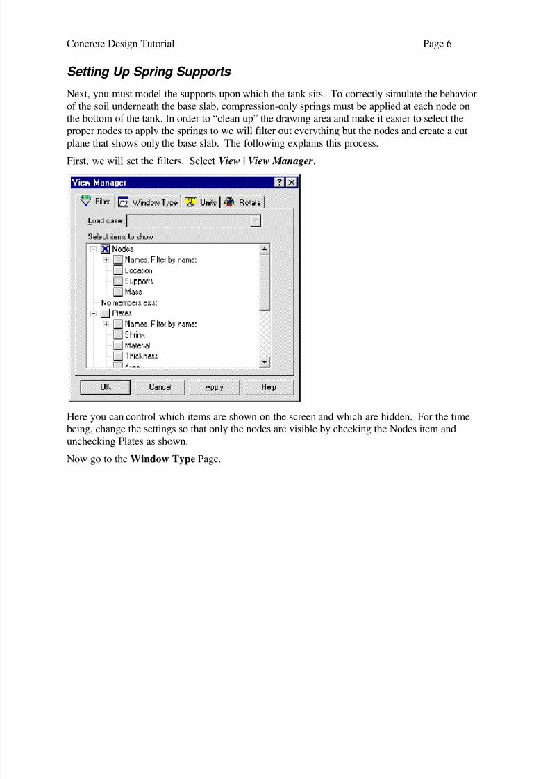
First, we will set the filters. Select View | View Manager.
Here you can control which items are shown on the screen and which are hidden. For the timebeing, change the settings so that only the nodes are visible by checking the Nodes item and
unchecking Plates as shown.
Now go to the Window Type Page.

8/6/2019 ACI Concrete WallSlab Design Tutorial
http://slidepdf.com/reader/full/aci-concrete-wallslab-design-tutorial 7/25
Concrete Design Tutorial Page 7
Change the Cut plane type to ZX Plan, then select “Y value” and set it to 0. Set the depth of
view in the Y direction to 1 ft. This will view a slice of the structure which is only 1 foot deep,thereby clipping out any of the nodes on the walls of the tank.
Now go to the Rotate page. In order to get the best possible perspective for node selection, we’d
like to be looking at a plan view of the model. Under Standard Orientations, select X-Z Plan. To
complete the process, press OK .
You should now be looking at a group of nodes in the same plane:

8/6/2019 ACI Concrete WallSlab Design Tutorial
http://slidepdf.com/reader/full/aci-concrete-wallslab-design-tutorial 8/25
Concrete Design Tutorial Page 8
Before we can create the springs we must know their stiffnesses. These will vary for each springdepending upon how much contact area on the bottom of the tank that they represent. In the case
of this model, there will be three different types of springs: interior springs, edge springs, and
corner springs.
Multiplying the tributary area of each spring by the soil modulus (100 pci), we arrive at
stiffnesses of 129.6 kips/inch, 64.8 kips/inch, and 32.4 kips/inch for the interior, edge, and corner
springs respectively.
We will create the interior springs first. Select all of the interior nodes by holding down the shiftkey, then clicking the mouse and dragging a box around them. Release the mouse button. The
interior nodes should all be highlighted.

8/6/2019 ACI Concrete WallSlab Design Tutorial
http://slidepdf.com/reader/full/aci-concrete-wallslab-design-tutorial 9/25
Concrete Design Tutorial Page 9
Now select Model | Create | New Spring.
Set the displacement spring stiffness to 129.6 k/in. Then move on to the Location page.

8/6/2019 ACI Concrete WallSlab Design Tutorial
http://slidepdf.com/reader/full/aci-concrete-wallslab-design-tutorial 10/25
Concrete Design Tutorial Page 10
For Standard Directions, choose -Y from the drop-down list. This ensures that the spring force
acts in the proper direction by extending the spring in the negative y direction from the nodes.Next move to the Options page.
Choose the Compression only option. This will make the springs tend to act more like the actual
soil would. Click OK . Your interior springs are now created. They may not be immediately
visible due to the fact that you’re looking directly down their lengths, but by using the View |
Rotate | Nudge menu item or the CTRL-arrow keys, you should be able to rotate the structure
enough to see them.
Now create the edge springs and corner springs in the same manner. Remember to select the
right nodes and use the correct stiffnesses!
Restraining Base Nodes
The next step that needs to be taken is to give the model some kind of restraint against lateraltranslation in the X and Z directions. To do this, we will select all of the nodes at the bottom of

8/6/2019 ACI Concrete WallSlab Design Tutorial
http://slidepdf.com/reader/full/aci-concrete-wallslab-design-tutorial 11/25
Concrete Design Tutorial Page 11
the tank and make them fixed against X and Z displacement. First use the mouse and the shift
key to draw a box around all of the base slab nodes. They should all become highlighted. Thenuse Model | Edit | Edit Nodes, and switch to the Support page:
Here you need to make sure that “Support Type” is selected rather than “Free from external
restraints”, and that “May vary” is the selected Support type. Indicate X Displacement and ZDisplacement as the fixed degrees of freedom. Then click OK. Your structure is now properly
supported.
To check supports, use View | View Manager and switch to the Filter page. Turn on Nodes,
Nodes/Supports, Plates, and Springs. Turn all of the other items off; they will only serve toclutter up the viewing area (This excludes the items under the Window branch - they should be
left alone for now). Move on to the Window Type page and set Cut Plane Type to None. Now
go to the Rotate page and select Left from the Standard Orientations list. Click OK . Your tank should appear like this:

8/6/2019 ACI Concrete WallSlab Design Tutorial
http://slidepdf.com/reader/full/aci-concrete-wallslab-design-tutorial 12/25
Concrete Design Tutorial Page 12
Water and Soil Pressure Loads
Now it is time to turn our attention to loading the structure. This design will consider loads from
two sources: Fluid pressure from the water in the tank, and soil pressure from the earthsurrounding the tank. The first step is to create service load cases for each source. Select Model
| Create | New Service Case.
Name this new load case “Water Pressure Loads” and designate it to be checked forserviceability criteria only. In the case of slab design, the serviceability criteria checked is the Z-
crack stress for crack control. Then move on to the Source page.

8/6/2019 ACI Concrete WallSlab Design Tutorial
http://slidepdf.com/reader/full/aci-concrete-wallslab-design-tutorial 13/25
Concrete Design Tutorial Page 13
Select Fluid Pressure Loads as the Source of Loads. Then click OK . This concludes the setup of
the “Water Pressure Loads” load case. Actual loads could not be placed on the tank at this time,however, we’ll come back to placing actual loads after we’ve created all the load cases.
Now create the “Soil Pressure Loads” load case using the same procedure that was used for the“Water Pressure Loads” case above. Be sure to change the source to Earth Loads!
Having creating the service load cases, it’s time to place loads on the structure. In
VisualAnalysis, loads are placed in whatever service load case is active in the current model
window. You can tell which load case is active in your model window by looking at theWindow toolbar at the bottom of the screen. There will be a box that says “Soil Pressure Loads”
or “Water Pressure Loads”. This area of the screen is shown below:
We will apply the water pressure loads first, so if your model window is on “Soil Pressure
Loads”, select “Water Pressure Loads” from the drop-down list.
To create loads use Model | Create | New Plate Load .

8/6/2019 ACI Concrete WallSlab Design Tutorial
http://slidepdf.com/reader/full/aci-concrete-wallslab-design-tutorial 14/25
Concrete Design Tutorial Page 14
Since these loads will apply to every element in the structure (assuming a full tank), select the
entire list of elements. Then proceed to the Magnitude page.
For Pressure Type, choose Hydrostatic variation. This is an easy way to apply a fluid-type load
to a large number of plate elements. Set the Axis to Y, the Fluid level to 18 ft (a full tank) and
the Density to 62.4 lb/ft3. Then click OK. Your loads should appear on the model. Remember
that you can always hide the loads on the screen via View | View Manager, Filter page. A large
group of loads like this can tend to blot out everything else.
Now we will create the soil loads in a similar manner. These can also be modeled effectively
using a hydrostatic load with an equivalent fluid density. First you must switch to the correctload case. Click on the load case display box at the bottom of the screen and switch to “Soil
Pressure Loads”. Then use Model | Create | New Plate Load and set up these loads similar to
how you did the others. There are a few things to keep in mind when doing this. First, don’tselect the base slab elements on the Placement page; those elements don’t see any soil loads!
Second, set the Fluid level on the Magnitude page to 15 feet; the tank is only buried that far.
Third, use an equivalent fluid density of 45 lb/ft3
for the Density of the soil. Fourth, make sure

8/6/2019 ACI Concrete WallSlab Design Tutorial
http://slidepdf.com/reader/full/aci-concrete-wallslab-design-tutorial 15/25
Concrete Design Tutorial Page 15
the Density value is negative; this will cause the load to act inward on the tank rather than
outward.
Factored Load Cases
Next, you must set up the factored cases, which are used for strength design purposes. Factoredcases provide us with a way to apply load factors on load cases that will be used in strength
checks. Select Model | Create | New Factored Case.
Name this case “Factored Water Loads” and designate it to be checked for strength only. Then
switch to the Factored Cases page.
Set the factor for the “Water Pressure Loads” load case to 1.7, and make sure that the factor for
Soil Pressure Loads is 0. Then click OK . Your first factored load case is complete.
Now create the factored case “Factored Soil Loads” using the same method as described above,
applying a load factor of 1.7 to the “Soil Pressure Loads” service case.

8/6/2019 ACI Concrete WallSlab Design Tutorial
http://slidepdf.com/reader/full/aci-concrete-wallslab-design-tutorial 16/25
Concrete Design Tutorial Page 16
You have now finished modeling the structure. This is a good time to save your work again.
Use File | Save or click on the M in the status bar at the lower left.
Analyze the Structure
Select Results | Analysis Wizard and start the analysis. We will do a first-order static analysiswith all load cases included.
Select a Static analysis. Click Next.
Set Analysis Type to First order. Click Next.

8/6/2019 ACI Concrete WallSlab Design Tutorial
http://slidepdf.com/reader/full/aci-concrete-wallslab-design-tutorial 17/25

8/6/2019 ACI Concrete WallSlab Design Tutorial
http://slidepdf.com/reader/full/aci-concrete-wallslab-design-tutorial 18/25
Concrete Design Tutorial Page 18
On the Mesh Information Properties page, name the mesh ‘A Long Side’, designate the design
type as Concrete Walls & Slabs, and set the live loads reduction factor to 1. Click Next.
On the Plates to Include in Mesh page, select all of the plates prefixed “S1-“. To do this first
click on the “Plate” column title which causes the list to be sorted by plate name. Then select the
first S1- plate in the list. Now scroll down the list to the last S1- plate and hold the shift key and
click on it this selecting all the plates between the first and last selection. Now click Next.

8/6/2019 ACI Concrete WallSlab Design Tutorial
http://slidepdf.com/reader/full/aci-concrete-wallslab-design-tutorial 19/25

8/6/2019 ACI Concrete WallSlab Design Tutorial
http://slidepdf.com/reader/full/aci-concrete-wallslab-design-tutorial 20/25
Concrete Design Tutorial Page 20
represent the thicknesses of the side walls and base slab that support this wall when loaded. The
top edge has no support, so its support width must be described by a value nearly zero.
Now switch to the Concrete page.
Set F’c to 3500 psi, and make sure that the High Seismic Risk box is unchecked.
The Z-Crack stress is particularly important when designing a tank. Because of leakage
concerns, we want the inside face of the wall to be designed for a Z-Crack stress of 95 ksi. In
order to determine whether the inside face is the ‘Top’ face or the ‘Bottom’ face for this wall,examine the orientation of the wall relative to the global coordinate axes and compare it to the
figure in the user’s guide. In this case, you will find that the inside face is the top face. Set the
Top Face Z-Crack Stress to 95 ksi and the Bottom Face Z-Crack Stress to 175 ksi.
Now proceed to the Reinforcement page:
Set Fy to 60 ksi and the Top Face and Bottom Face Cover to 2 inches. We will also use a BarSpacing Module of 3 inches, a Max. Bar Spacing of 12 inches, and a Minimum Bar Size of #4.

8/6/2019 ACI Concrete WallSlab Design Tutorial
http://slidepdf.com/reader/full/aci-concrete-wallslab-design-tutorial 21/25
Concrete Design Tutorial Page 21
Make sure that the Use Metric Bar Sizes box is unchecked. Anticipating greater moment in the
vertical bars, place them in the outside layer. Check the box that tells the program to Use ACIWall Minimum Reinforcement.
Now click OK . You have finished setting up the design mesh and its parameters.
Design the Slab
Select Results | Plate Design | Design Plates. The size table will appear:
The Size Table page contains a list of the different thicknesses that the design module tried, and
a brief summary of approximate results. We can see that the first three sizes are clearly not good
choices; they don’t satisfy the shear strength criteria. The 18-inch wall is close; however, uponconsulting the Detail Check page for the exact values (based upon the chosen reinforcement
pattern) we find that the 18-inch wall still isn’t adequate. Select the 20-inch wall, then go to the
Top Mat page.

8/6/2019 ACI Concrete WallSlab Design Tutorial
http://slidepdf.com/reader/full/aci-concrete-wallslab-design-tutorial 22/25
Concrete Design Tutorial Page 22
The Top and Bottom Mat pages give you a chance to review the reinforcement layout and makemodifications to suit your preferences. For this tutorial we will accept the program’s design and
move on to the Detail Check page.
This page provides a short summary of the results for each detail region that you have designed
for this mesh. Note that if you made changes to the layout on the Top Mat or Bottom Mat
pages, the values on this page will reflect those changes. It looks like everything’s fine for now,so click OK to accept the design.
You will notice a small progress box that says “Performing Unity Checks” in the lower left-hand
corner of the screen. Don’t worry about it for now; in this particular design we won’t use the
unity check results just yet.

8/6/2019 ACI Concrete WallSlab Design Tutorial
http://slidepdf.com/reader/full/aci-concrete-wallslab-design-tutorial 23/25

8/6/2019 ACI Concrete WallSlab Design Tutorial
http://slidepdf.com/reader/full/aci-concrete-wallslab-design-tutorial 24/25
Concrete Design Tutorial Page 24
Create and Design Additional Meshes, if Desired
At this point you would go back and design a short wall of the tank and the tank bottom, using a
similar procedure as described above. For the purposes of this tutorial we will skip this step andproceed to reporting.
Generate a Design Report
Now we would like to see a printout of the results obtained from the Slab/Wall module. Double-
click on any one of the elements in the design mesh (you must still be in the design window). A
report will come up, displaying information on the design mesh parameters, the reinforcementdetails, and the applied and allowable forces/stresses at each node of that particular element.
A sample report generated from this tutorial project is shown below:
VisualAnalysis 3.5 ReportOctober 4, 1999 2:12:11 p.m.
Project: Tank Problem
File: D:\va31\tank.Vap
Engineer: Joe B Engineer
Billing: IES
Default Units: Feet, Kips, Degrees, ºFahrenheit, Seconds.
Design Plate ResultsLoad Cases Checked For Strength
ID Case Name
1 Factored Fluid Loading
2 Factored Soil Pressure
Concrete Wall/Slab (ACI) ReportFor Plate: BO504
F’c = 576 ksf, Fy = 8640 ksf Top Cover = 0.125 ft, Bottom Cover = 0.125 ft
Detail Spacing Module = 0.5 ft, Detail Maximum Spacing = 1.5 ft
Top Bar Z-Crack Stress = 13680 ksf, Bottom Bar Z-Crack Stress = 16560 ksf ACI minimum wall steel provisions will be checked.
Horizontal bars are the outside mat.Horizontal Detail Region Heights: Bottom = 10 ft, Middle = 10 ft, Top = 10 ft
Vertical Detail Region Widths: Left = 6.66667 ft, Center = 6.66667 ft, Right = 6.66667 ftSupport Widths: Left = 1 ft, Right = 1 ft, Bottom = 1 ft, Top = 1 ft
Top Vertical Steel Details:
Left Center RightTop #4@ 1 ft O.C. #4@ 1 ft O.C. #4@ 1 ft O.C.
Middle #3@ 0.5 ft O.C. #4@ 1 ft O.C. #3@ 0.5 ft O.C.
Bottom #4@ 1 ft O.C. #4@ 1 ft O.C. #4@ 1 ft O.C.
Bottom Vertical Steel Details:
Left Center Right
Top #3@ 0.5 ft O.C. #3@ 0.5 ft O.C. #3@ 0.5 ft O.C.
Middle#3@ 0.416667 ft O.C. #4@ 1 ft O.C.#3@ 0.416667 ft O.C.Bottom#3@ 0.416667 ft O.C. #3@ 0.5 ft O.C.#3@ 0.416667 ft O.C.
Top Horizontal Steel Details:
Left Center RightTop #4@ 0.5 ft O.C. #6@ 1.5 ft O.C. #4@ 0.5 ft O.C.
Middle #4@ 0.5 ft O.C. #6@ 1.5 ft O.C. #4@ 0.5 ft O.C.

8/6/2019 ACI Concrete WallSlab Design Tutorial
http://slidepdf.com/reader/full/aci-concrete-wallslab-design-tutorial 25/25
Concrete Design Tutorial Page 25
Bottom #4@ 0.5 ft O.C. #6@ 1.5 ft O.C. #4@ 0.5 ft O.C.
Bottom Horizontal Steel Details:
Left Center RightTop #7@ 1 ft O.C. #6@ 1.5 ft O.C. #7@ 1 ft O.C.
Middle #5@ 0.5 ft O.C. #6@ 1.5 ft O.C. #5@ 0.5 ft O.C.
Bottom #5@ 0.5 ft O.C. #6@ 1.5 ft O.C. #5@ 0.5 ft O.C.
Vertical Reinforcement:
Node Mu+ Phi Mn+ Mu- Phi Mn- M+ Z+ M- Z-ID K-ft/ft K-ft/ft K-ft/ft K-ft/ft K-ft/ft ksf K-ft/ft ksf
N535 0.55644 13.26673 0.82893 12.01765 0.32732 823.52879 0.48761 1733.74170
Horizontal Reinforcement:
Node Mu+ Phi Mn+ Mu- Phi Mn- M+ Z+ M- Z-
ID K-ft/ft K-ft/ft K-ft/ft K-ft/ft K-ft/ft ksf K-ft/ft ksf
N535 1.33777 18.36029 2.37317 18.36029 0.78692 1736.35029 1.39599 3080.25075
Shear:
Node Vu Phi Vc
ID K/ft K/ft
N534 2.62298 17.33719
This concludes the slab/wall tutorial.