aci 544.7r16–design and construction of fiber reinforced ... · - one-pass lining for road and...
TRANSCRIPT

The Concrete Conventionand Exposition
ACI 544.7R16–Design and Construction of Fiber Reinforced Precast
Concrete Tunnel Segments
Mehdi Bakhshi, PhD, PEAECOM, New York

The Concrete Conventionand Exposition
Outline
• Introduction to Precast Segments
• Strength Design Method for Segments (ULS): – Governing Load Cases, Load Factors & Load Combinations
• Methods of Analysis for Governing Load Cases
• Design with Fibers as an Alternative to Reinforcing Bars
• Strength Design Example for FRC Tunnel Segment
• Future Materials to be Added to Document
• Conclusions

The Concrete Conventionand Exposition
Precast Segmental Tunnel Lining• Serves as both initial ground support & final lining in modern
TBM tunnels• Providing the required operational cross‐section • Controlling groundwater inflow
The Concrete Conventionand Exposition
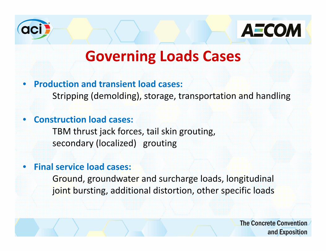
Governing Loads Cases
• Production and transient load cases:Stripping (demolding), storage, transportation and handling
• Construction load cases:TBM thrust jack forces, tail skin grouting, secondary (localized) grouting
• Final service load cases: Ground, groundwater and surcharge loads, longitudinal joint bursting, additional distortion, other specific loads
The Concrete Conventionand Exposition
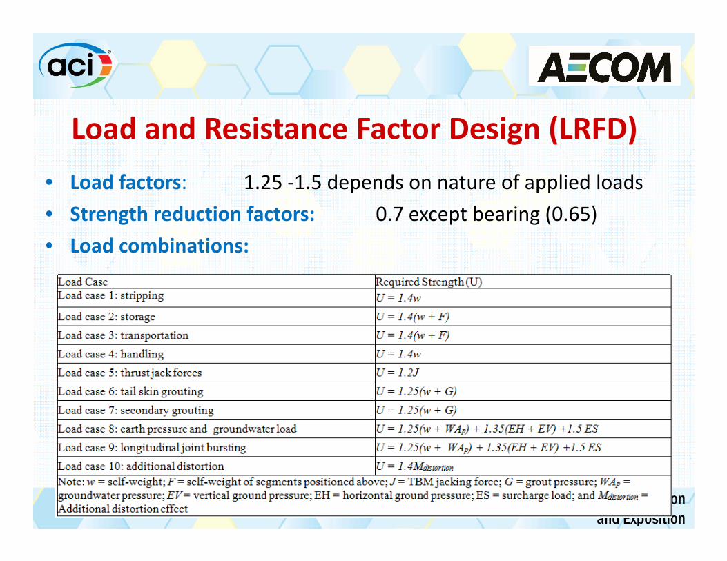
Load and Resistance Factor Design (LRFD)• Load factors: 1.25 ‐1.5 depends on nature of applied loads• Strength reduction factors: 0.7 except bearing (0.65)• Load combinations:
The Concrete Conventionand Exposition
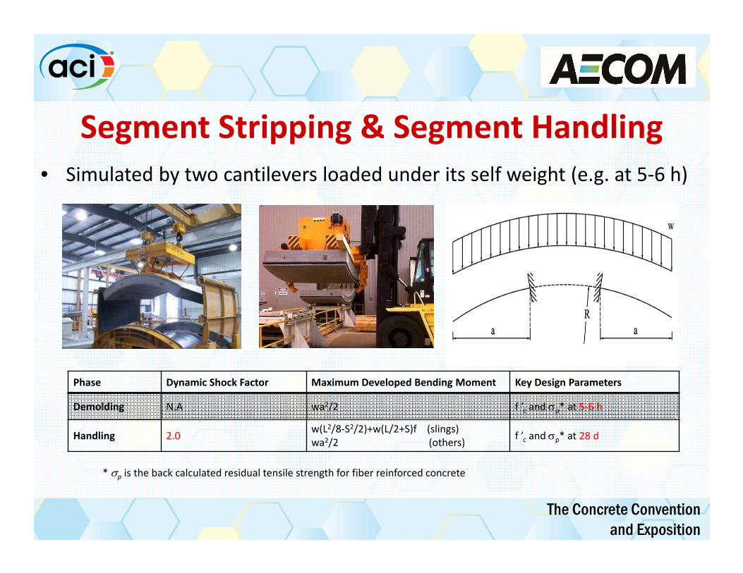
Segment Stripping & Segment Handling• Simulated by two cantilevers loaded under its self weight (e.g. at 5‐6 h)
Phase Dynamic Shock Factor Maximum Developed Bending Moment Key Design Parameters
Demolding N.A wa2/2 f ’c and p* at 5‐6 h
Handling 2.0 w(L2/8‐S2/2)+w(L/2+S)f (slings)wa2/2 (others) f ’c and p* at 28 d
* p is the back calculated residual tensile strength for fiber reinforced concrete

The Concrete Conventionand Exposition
Segment Storage & Transportation• Simulated by simply supported beams loaded under its self‐weight and
eccentricity (e.g. 5‐6 h)• Segments comprising a ring piled up within one stock
* p is the back calculated residual tensile strength for fiber reinforced concrete
Phase Dynamic Shock Factor Maximum Developed Bending Moment Key Design Parameters
Storage N.A w(L2/8‐S2/2)+F1e w(S2/2)+ F1e
f ’c and p* at 5‐6 h
Transportation 2.0 w(L2/8‐S2/2)+ F2e w(S2/2)+ F2e
f ’c and p* at 28 d
The Concrete Conventionand Exposition
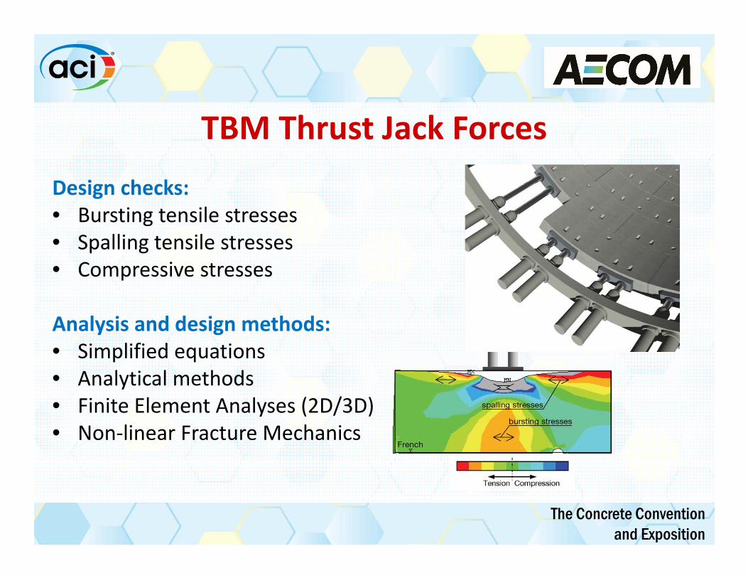
TBM Thrust Jack ForcesDesign checks:• Bursting tensile stresses• Spalling tensile stresses• Compressive stresses
Analysis and design methods:• Simplified equations • Analytical methods• Finite Element Analyses (2D/3D)• Non‐linear Fracture Mechanics

The Concrete Conventionand Exposition
Analysis & Design Methods for Jack ForcesFEM
Analytical Methods (Iyengar, 1962)
h-2e
hanc
DAUB
)2(4.0;2
125.0 ancburstanc
ancpuburst ehd
ehh
PT
ACI 318
)2(5.0;125.0 ancburstanc
puburst ehdh
hPT
Simplified Equations

The Concrete Conventionand Exposition
Tail Skin and Secondary Grouting Pressure
g = 225 kPa
g = 264.5 kPa
g = 245 kPa1573 kN
Axial Forces
114 kN.m
Bending Moments
• To fill a local gap b/w lining & excavation profile after primary grouting
• Simulated in 2D• Interaction with ground is modeled
by radial springs• Grout pressure applied w/ triangular
distribution
• Simulated in 2D by a solid ring• Grout pressure at crown is slightly higher
than groundwater pressure• Invert grout pressure calculated from
equilibrium b/w grout pressure, self-weight and shear stresses of grout
• Radial pressure applied w/ linear distribution
Tail Skin Grouting Secondary Grouting

The Concrete Conventionand Exposition
Ground and Groundwater Loads
Beam‐Spring Method
Elastic Equation Method
Finite Element Method (FEM)
Discrete Element Method (DEM)

The Concrete Conventionand Exposition
Longitudinal Joint Bursting ForcesDesign checks:• Bursting tensile stresses• Compressive stresses
Analysis and design methods:• Simplified equations • Analytical methods• Finite Element Analyses (2D/3D)
DAUB (2013)
Compressive Stresses
Tensile Stress

The Concrete Conventionand Exposition
Fibers as an Alternative to Reinforcing BarsAdvantages• Cost saving (10-40%)• Improved precast production efficiency• Reduce spalling or bursting of concrete cover at
vulnerable edges and corners• Ductility & robustness• Crack width reduction• High strength against unintentional impact loads
The Concrete Conventionand Exposition
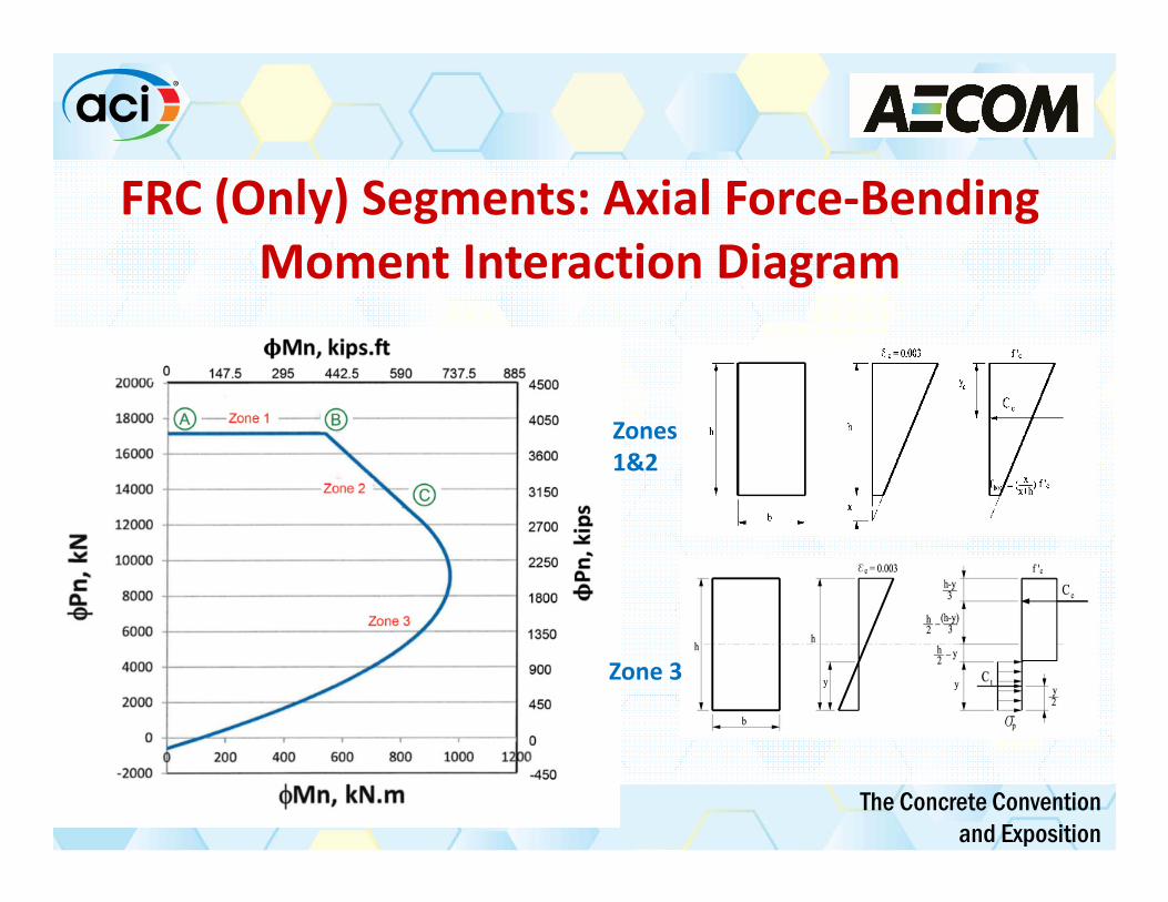
FRC (Only) Segments: Axial Force‐Bending Moment Interaction Diagram
Zones 1&2
Zone 3
The Concrete Conventionand Exposition
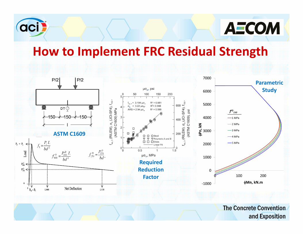
How to Implement FRC Residual Strength
ASTM C1609
Required Reduction Factor
Parametric Study

The Concrete Conventionand Exposition
FRC Segments: Choice of Constitutive Law

The Concrete Conventionand Exposition
Strength Design Example–FRC SegmentGeometry and Strength Parameters
• Di = 5.5 m (18 ft)• b = 1.5 m (5 ft)• h = 0.3 m (12 in)• Lcurved = 3.4 m (11.2 ft)• f’c @ 4h: 15 MPa (2,200 psi)• f’c @ 28d: 45 MPa (6,500 psi)• f1 = 3.8 MPa (540 psi)• f’D150 @ 4h: 2.5 MPa (360 psi)• f’D150 @ 28d: 4 MPa (580 psi)• THTBM = 20,000 kN on 16 jack pairs• Jack Shoes Contact Area: 0.2 x 0.87m
• Ring composed of 5+1 segments• Tunnel excavated in fractured rock

The Concrete Conventionand Exposition
Design Checks for Strength (ULS)
Phase Specified Residual Strength,MPa (psi)
Maximum Bending Moment,kNm/m (kipf-ft/ft)
Bending Moment Strength, kNm/m (kipf-ft/ft)
Demolding 2.5 (360) 5.04 (1.13) 26.25 (5.91)Storage 2.5 (360) 18.01 (4.05) 26.25 (5.91)Transportation 4.0 (580) 20.80 (4.68) 42.00 (9.44)Handling 4.0 (580) 10.08 (2.26) 42.00 (9.44)
ACI 318
)22.1(1775347.0
100055.172.12.1:
)2.1(1741277.187.0
100032.172.12.1:
MPapsidaTdirectionRadial
MPapsidh
TdirectionTangential
burstl
burstp
burstanc
burstp

The Concrete Conventionand Exposition
Future Materials: Design for Service‐Crack Widthtop
strains
ftop = 17.1 MPa (2.48 ksi)
stresses
Fiber properties:f’D150 = 4 MPa (0.58 ksi)
p = 0.34 x 4 MPa = 1.36 MPa (0.197 ksi)
1524 mm (60 in)
305 mm (12 in)
x=179 mm(7.04 in)
fc,t
p = 1.36 MPa (0.197 ksi)
topst
sb
strains
ftop = 18.45 MPa(2.676 ksi)
Fst = 1,956 kN (440 kips)
stresses
10 #4 (Asb = 1290 mm2)
10 #4 (Ast = 1290 mm2)
38 mm (1.5 in)
1524 mm (60 in)
229 mm (9 in)
305 mm (12 in)
x=148 mm(5.8 in)
38 mm (1.5 in)
Fsb = 2,122 kN (477 kips)
Steps for FRC segments:
1‐ Determination of neutral axis
2‐ Determination of compressive/tensile strains at extreme fibers
3‐ Calculation of crack width using gauge length concept

The Concrete Conventionand Exposition
Future Materials: Crack Width Reduction Under Excessive Service Loads
Service Loads:M = 239 kN.m (177 kips‐ft) N = 2,068 kN (465 kips)
Alternatives:1‐ RC2‐ FRC
Maximum Crack Width in RC Segments Maximum Crack Width in FRC Segments
ACI 224.1R (2007) - Gergely & Lutz
0.10 mm(0.0039 in)
fib Model Code (2010)CNR-DT 204 (2006)
0.10 mm(0.0040 in)
ACI 224.1R (2007) - Frosch 0.14 mm(0.0056 in) RILEMTC 162-TDF (2003) 0.04 mm
(0.0017 in)JSCE (2007) 0.14 mm
(0.0053 in)DAfStb (2012) 0.047 mm
(0.0018 in)EN 1992-1-1 (2004) 0.07 mm(0.0028 in)
FRC results in ~45% crack width reduction in average

The Concrete Conventionand Exposition
Future Materials: Allowable SLS Crack Width
Requirement Class
Designation Application Requirement Allowable Crack Width
AT1 Largely dry - One-pass lining with very tight waterproofing requirements - Portal areas
Impermeable 0.20 mm (0.008 in)
AT2 Slightly moist
- One-pass lining for road and railway tunnels with normal waterproofing requirements (excluding portals)
Moist, no running water in tunnel
0.25 mm (0.010 in)
AT3 Moist - One-pass lining without waterproofing requirements - two-pass lining systems
Water drippingfrom individual spots
0.30 mm (0.012 in)
AT4 Wet - One-pass lining without waterproofing requirements - two-pass lining as drained system
Water running in some places
0.30 mm (0.012 in)
Concrete Codes: ‐ ACI 224.1R (2007): 0.3 mm (0.012 in)‐ EN 1992‐1‐1 (2004): 0.3 mm (0.012 in)‐ Model Code (2010): 0.2 mm (0.008 in)
Tunnel Codes: ‐ LTA (2007): 0.3 mm (0.012 in)‐ DAUB (2013): 0.2 mm (0.008 in)‐ JSCE (2007): 0.004 dc‐ ÖVBB (2011):

The Concrete Conventionand Exposition
Ongoing Studies: Crack Width vs. Infiltration
Flow through Concrete
y = 39.476x ‐ 3.1581
y = 24.49x ‐ 1.8367
y = 8.2908x ‐ 0.9534
0
2
4
6
8
10
12
14
0 0.1 0.2 0.3 0.4
Flow
Rate Co
efficient (%
)
Crack Width (mm)
PCPC ‐ Exp DataRCRC ‐ Exp DataFRCFRC ‐ Exp Data
1212
33 glIwd
PlwQ
050100150200250300350400450500
0 0.1 0.2 0.3
Initial Flow Rate (liter/h)
Crack Width (mm)
Flow Rates for FRC
h=21 mh=14 mh=7 mAssumptions
l = 1.5 m
d = 0.3 m
T = 20o C
water preassure
Flow through parallel plates
0
100
200
300
400
500
600
700
0 0.1 0.2 0.3
Initial Flow Rate (liter/h)
Crack Width (mm)
Flow Rates for FRC
d=0.23 md=0.3 md=0.38 m
Assumptions
h = 21 m
l = 1.5 m
T = 20o C
segment thickness
0
500
1000
1500
2000
2500
0 0.1 0.2 0.3Initial Flow Rate (liter/h)
Crack Width (mm)
Flow Rates RC vs. FRC
RCFRC
Assumptions
h = 21 m
d = 0.3 m
l = 1.5 m
reinforcement type
The Concrete Conventionand Exposition
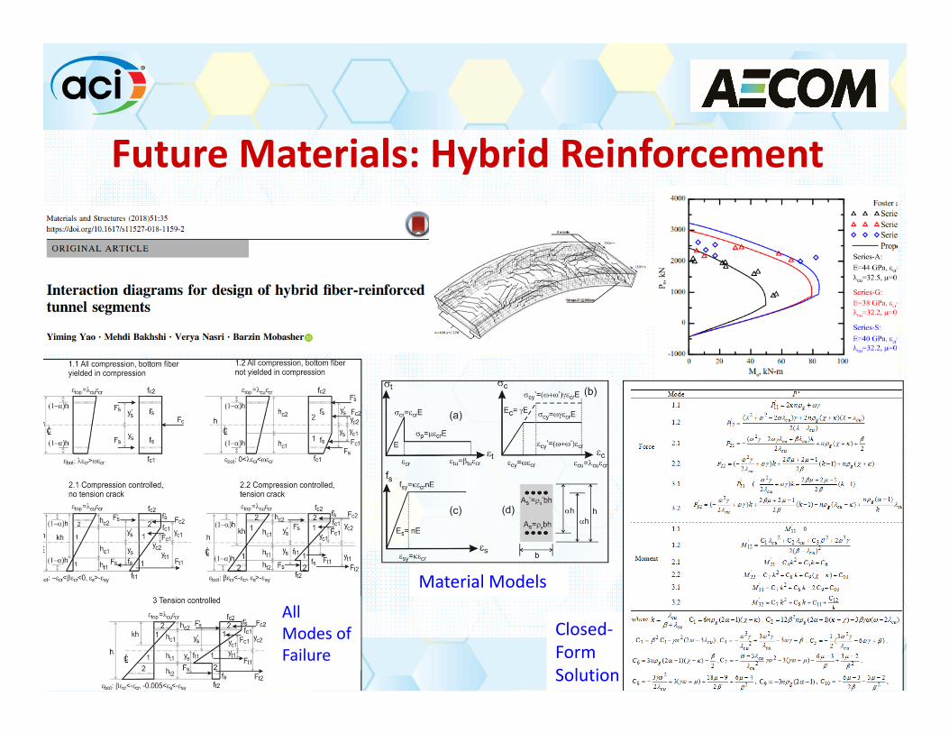
Closed‐Form Solution
Future Materials: Hybrid Reinforcement
Material ModelsAll Modes of Failure

The Concrete Conventionand Exposition
Conclusion• ACI 544.7R successfully addressed the demand in industry for a guide on FRC segments
• In mid‐size tunnels use of fiber reinforcement can lead to elimination of steel bars required for strength, resulting in construction cost saving of up to 40%.
• Use of fiber in tunnel segments results in reduction of crack width by ~45% under the service load for Serviceability Limit State (SLS) design.
• Service design and hybrid reinforcement strength design will be added in the future to ACI 544.7R.

The Concrete Conventionand Exposition
Thank you for your attention
Mehdi Bakhshi, PhD, PESenior Tunnel Engineer at AECOM
Member of ACI committees 305, 350, 506, 544, and 533 [email protected]
D 212.896.0257 C 480.370.1685125 Broad St, 16th floor, New York, NY 10004