achieving zero discharge - infohouseinfohouse.p2ric.org/ref/30/29505.pdf · achieving zero...
TRANSCRIPT

Achieving Zero Discharge ASHTA Chemicals' Zero Discharge Process Water Recovery System
Theodore P. Kircher and James T. Tallon
Industrial process waters and stormwater runofl are attracting greater regula- t o y attention. To meet the increasingly s trlngent regulatory requi remen ts, industry will need to deuelop innovative solu- tions. This article de- scribes how ASHTA Chemicals, Inc. responded to the challenge of facility- wide water management by designing a "zero discharge" system at its ptlncipal manuf acturing sfte.
PROCESS WATERS GENERATED from industrial manufacturing opera- tions are facing increasingly stringent discharge requirements. In addition, stormwater from process areas is attracting greater regu- latory attention. To meet these regulatory requirements, industry will need to develop innovative solutions to control or eliminate constituents associated with these waters. This may require any of a number of approaches, including application of state-of-the-art treatment technology, use of substitute processes or alternate chemical feedstocks, reuse and recovery of materials, waste minimi- zation and pollution prevention procedures, and other site-specific water management practices. This article summarizes the approach that ASHTA Chemicals, Inc. has followed to address facilitywide water management challenges at its principal manufacturing site, as well as the solutions it has developed and is now in the process of implementing.
The ASHTA Facility ASHTA's principal manufacturing operations are located on a 72-
acre site in Ashtabula, Ohio, approximately 60 miles east of Cleveland on Lake Erie's south shore. ASHTA is the nation's second-largest manufacturer and marketer of potassium hydroxide (KOH) and related potassium products. The facility processes potassium chloride (KCl), a solid, into liquid potassium hydroxide by dissolving it in water to form a nearly saturated brine solution and passing the solution through electrolytic cells. The process also yields chlorine (Cl,) a t a ratio of one part chlorine to 1.73 parts potassium hydroxide. Products manufactured at the facility include liquid and dry potassium hydrox- ide (or caustic potash), liquid and dry potassium carbonate (&CO ) . 3 ' chlorine, hypochlorite bleach, hydrcgen (HJ, and chloropicrin (CCl,NO,).
The four primary sources of water managed at this ASHTA facility include:
Theodore P. Kircher is technical and environmental manager for ASHTA Chemi- cals, Inc., in Ashtabula, Ohio. James T. Tallon is a senior technical specialist with ENSR Consulting and Engineering in Pittsburgh, Pennsylvania.
CCC 1053-4253/040371-15 (0 1994 John Wiley & Sons, Inc.

1
Theodore P . Kircher and James T. Tallon
The toxicity of the effluent, as determined with respect to specifk aquatic lffe species, is being used to further defne the quality of the effluent limits.
1.
2.
3.
4.
Process water, which contains part-per-million (ppm) levels of mercury and percent levels of total dissolved solids (TDS), largely in the form of potassium chloride; Stormwater collected from process areas, which can contain part-per-billion (ppb) levels of mercury and up to several hundred ppm levels of dissolved salts; Leachate from a closed landfill, which contains low levels of mercury, dissolved salts, and organics (mainly humic materi- als); and Noncontact cooling water, which contains ppb levels of mer- cury when it enters the plant.
At the time the facilitywide water management project discussed in this article was begun, the plant used water from Lake Erie for once- through noncontact cooling of various portions of the manufacturing process, then discharged the water back to the lake along with stormwater and treated process effluent streams.
Needed A New Water Management Strategy The water discharged from the ASHTA facility is regulated by the
National Pollutant Discharge Elimination System (NPDES). The facility’s pre-1994 NPDES permit allowed a maximum discharge of 26 grams of mercury a day (with an average of 11 grams of mercury a day). This permit was essentially a mass-loading permit and was not based on a specific discharge mercury concentration. In addition, it was a “net permit,” meaning that it did not count as part of its discharge limitations the mercury that ASHTA took in from Lake Erie, used in its once-through cooling water, and then discharged back into the lake. It was also a technology-based permit that required ASHTA to use the best demonstrated available technology (BDAT)-which for mercury cell chlor-alkali plants is mercuric sul- fide precipitation. This process produces a solid waste composed mainly of mercuric sulfide (known as the EPA-designated waste K106). K106 is barred from land disposal in the United States and requires costly thermal retorting as its disposal BDAT.
The water discharge from the ASHTA facility is piped directly to an outfall leading to Lake Erie. Lake Erie, as part of the Great Lakes, has been incorporated into the Great Lakes Initiative, which is moving industries and communities from technology-based to water quality-based treatment. The requirements identified in the pro- posed Great Lakes Water Quality Guidance (GLWQG Unoficial Prepublication Copy, March 31, 1993) emphasize that certain con- stituents should be removed to very low levels in water that is to be discharged to the Great Lakes. Water quality-based standards for mercury can vary from a few parts per billion to levels below analyti- cal detection limits. In addition, the toxicity of the effluent, as determined with respect to specific aquatic life species, is being used to further define the quality of the effluent limits.
372 Pollution Prevention Review /Autumn 1994

Achieving Zero Discharge
ASHTA decided that the most conscientious and long-term approach to complying with its new NPDES permit was a ‘’Z2io dischiiiije” sysieiii.
These discharge standards strongly influenced the permit re- quirements that were specified in ASHTA’s NPDES permit when it came up for renewal in 1994. The new NPDES permit for ASHTA requires a maximum of 12 parts per trillion (ppt) of mercury in the discharge leaving the facility. The 1994 permit also requires that the discharge from the ASHTA facility pass toxicity tests for two aquatic life species: the water flea (Ceriodaphnia dubia) and fathead minnow (Phimephales promelas). Additional tests for trace metals, free chlo- rine, and organics, along with the monitoring and control of pH and temperature ranges and limitations, are included as part of the permit monitoring requirements.
The permit limit that drove the development of ASHTA’s new water management strategy was the mercury limitation of 12 ppt. This new mercury limit, although concentration-based, is below the analytical detection limit of state-of-the-art instrumentation. Since the noncontact cooling water obtained from Lake Erie contains mercury, in order to comply with the new discharge limit, the mercury would need to be removed prior to returning the water to Lake Erie. For this reason, any treatment strategy developed by ASHTA needed to take into account the fact that the noncontact cooling water that had not required treatment in the past would, if discharged, need to be treated in the future.
Selecting an Approach
addressing the proposed new permit requirement. These included: ASHTA first examined several discharge-based approaches to
Seeking net permitting of the treated process waters; Using a mixing zone at the outfall into Lake Erie; and Discharging the treated process water to a publicly owned treatment works (POW).
All of these potential approaches were rejected. The net permitting and mixing zone options were dismissed as short-term discharge alternatives; in addition, it was concluded that a mixing zone would be difficult to properly define and monitor. The POTW option was judged not to be technically feasible.
Since none of the discharge-based approaches appeared viable, ASHTA decided that the most conscientious and long-term approach to complying with its new NPDES permit was to investigate, concep- tualize, design, and install a “zero discharge” system. The initial investigations that were conducted to identify potential management options are summarized below.
Toxicity studies Beginning in 1989, ASHTA conducted Toxicity Identification
Evaluations (TIES), using the water flea and the fathead minnow, in order to identify potential sources of toxicity in the plant discharge.
~ ~~~~~ ~ ~
Pollution Prevention Review /Autumn 1994 3 73

Theodore P . Kircher and James T . Tallon
Exhibit 1. Summary of Stream Characterization Data
Average Flow, TDS, Mercury, ~
Stream GPD PPm PPb PH
Effluent sump Brine cell flushing Boiler blowdown KOH storage tank area D.I. water regenerant Leachate Chlorinated water Stormwater
5,500 750
14,400 6,600 3,700 6,400
18,000 18.6
107,370 84,060
1,250 19,100 11,190 27,210
900 697
19,800 18,800
<0.2 101 53 59 35 8.6
>14 __
<3 7.5 - 8.5
>10 3 - 12
>10 ~ 2 . 5 >8.0
The toxicity testing indicated that salt, as potassium chloride, was toxic to the species. Using the results developed, it was determined that, to comply with the proposed 1994 permit toxicity limitations, the combined discharge from the ASHTA facility could be allowed a maximum salt concentration of only 75 ppm. Since the treated process water discharge from the ASHTA facility contained 20 to 100 grams of KC1 per liter, the projected discharge requirement would be dificult to achieve. Even diluting the process water through contin- ued use of noncontact cooling water from Lake Erie, in quantities of up to 5.5 million gallons a day, would only reduce the concentration to 500 ppm of KC1 in the process water stream.
ASHTA also conducted a TRE to identify the streams that im- parted the greatest concentrations of salt and mercury to the waste- water process. The TRE examined various process and non-process streams to determine salt and mercury concentrations and associated flow rates. The results gathered from the TRE are represented in Exhibit 1.
The findings developed from the toxicity studies can be summa- rized as follows:
A 200-fold decrease in salt concentration would be required for NPDES compliance. Extremely high salt concentrations were present in many streams, except chlorinated water and stormwater. Chlorinated water contains low TDS and mercury levels, indicating the need for minimal treatment. Chlorinated water, due to its low pH, can be used to neutralize other process streams. Stormwater was generally a small daily flow with minimal mercury concentrations.
3 74 Pollution Prevention ReuiewlAutumn 1994

Achieving Zero Discharge
Exhibit 2. Chemistries and Processes Investigated for Mercury-in-Water Treatment Technology
Chemistries Processes
Inorganic sulfide precipitation Standard filtration Organic sulfide precipitation Reverse osmosis Carbamate precipitation Activated carbon Iron hydroxide coprecipitation Aluminum hydroxide coprecipitation Ultrafiltration Elemental mercury reduction Chloride-based chemistry
Thiol-group ion exchange
Review of mercury treatment technologies In the early stages of its investigation, ASHTA conducted a review
of the literature regarding mercury-in-water treatment technologies, reading journal articles and equipment manufacturers' literature. This review included evaluating the potential chemistries and the physical processes and equipment available for achieving the requi- site ppb to ppt levels of mercury. Potential technologies identified from this investigation are listed in Exhibit 2.
Bench-scale testing of the technologies indicated that the high chloride content of the combined process water hindered the removal of mercury when chemistry-based technologies were used. The pre- dicted performances of mercury-removal chemistries, based on the experiences of manufacturers with much lower levels of TDS, were not met at ASHTA because of the much higher levels of TDS present in ASHTA's process water.
In parallel with these investigations, ASHTA improved its mer- cury precipitation process by optimizing the pH and chemistry while improving the maintenance of vertical leaf filters. Performance testing revealed that the following procedure would optimize precipi- tation of mercury:
Dechlorinating the batch; and
Lowering the batch to a pH of 4.0 to 4.5 in the presence of free chlorine, thus converting all mercury to mercuric chloride;
Adding sulfide to precipitate the mercury a t a pH of 4.5 to 5.5.
Inorganic sulfide precipitation provided the lowest mercury-in-water concentration level of any chemistry-based technology.
Exhibit 3 provides an overview of the primary technologies that were examined for reducing the mercury content of the plant water. As shown in this exhibit, none of the technologies approached the level of treatment required for discharge. Even in combination (i.e., inor-
Pollution Preuentlon Reolew /Autumn 1994 3 75

Theodore P. Kircher and James 7'. Tallon
Exhibit 3. Mercury Removal Treatment Technology Performance: Predicted versus Actual Optimum
Predicted Hg, Actual Hg, Technology PPb PPb
Inorganic sulfide precipitation Insoluble Organic sulfide precipitation 2.0 Carbamate precipitation 0.2 Iron hydroxide coprecipitation 0.2 Aluminum hydroxide coprecipitation 0.5 Reverse osmosis 1.0 Activated carbon 5.0 Thiol-group ion exchange 5.0 Ultrafiltration 5.0
5.0 125.0 140.0 150.0 150.0
5.0 10.0 3.5
15.0
ganic sulfide precipitation, followed by thiol-group ion exchange), the desired level of treatment could not be obtained. The best achievable level was found to be 3.5 ppb, which is roughly two orders of magnitude higher than the desired level of treatment.
Even if a treatment strategy had been identified at this point, it was realized that the discharge limits of the facility would need to be reduced in the future as advances in analytical instrumentation lower the analytical detection limit. Future developments could make even the best available treatment technology inadequate.
Based on results of several treatability investigations, it was concluded that no treatment method available could even consis- tently reduce mercury to below detection levels-let alone reduce it to 12 ppt. Thus, no discharge of water would be possible under the proposed permit, since the best treatment approach would not elimi- nate all detectable levels of mercury.
Developing a Closed-Loop System ASHTA conducted a review of closed-loop systems and examined
the application of evaporator systems, reverse osmosis, and other physical separation processes. All the technologies examined had assnciated concentrate or blowdown streams. Based on the water balances around the ASHTA facility and its processes, the investiga- tors came up with the concept of a cooling tower that could absorb the water from the closed-loop process. The process would require re- moval of mercury and potassium chloride in order to provide appro- priate water quality for the closed-loop system cooling tower.
Development of ASHTA's new process began with stream charac- terizations, including consideration of water flow rates, mercury concentrations, pH, TDS, chlorides, and iron. Approximately 90
376 Pollution Prevention ReviewIAutumn 1994

Achieving Zero Discharge
The new system eliminates the discharge of mercury-bearing water into Lake Erie.
percent of the TDS present in the water was determined to be potassium chloride, which helped simplify the problem of salt re- moval.
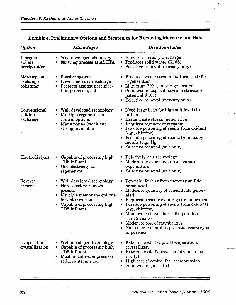
Options for removing mercury and salt ASHTA reviewed preliminary design options for removing and
recovering mercury and salt from the water that was to be recycled back to the cooling tower. Exhibit 4 sets out the various removal options considered and summarizes the advantages and disadvan- tages of each.
Two conventional treatment approaches were identified as being capable of reducing the dissolved solids content of the water to low levels: reverse osmosis and ion exchange. In addition, ion exchange and sulfur-impregnated carbon were selected for investigation with respect to mercury removal. The mercury and salt recovery pilot screening test results are set out in Exhibit 5.
Testing of the sulfur-impregnated carbon system revealed that it could achieve relatively high mercury rejections (greater than 99 percent). The ion exchange testing (which included the use of initial weak acidbase resins, followed by strong acid base resins) yielded poor results, with high TDS discharges and generation of large chemical and water regeneration streams.
Testing of reverse osmosis demonstrated high salt rejections (typically greater than 90 percent), high salt recoveries (over 90 percent on a TDS basis), and high mercury rejections (typically greater than 80 percent, and over 90 percent with proper pH control), as shown in Exhibit 6.
For these reasons, reverse osmosis was selected as the technology for removing and recovering mercury and salt from the water.
Elements of the Zero Discharge Strategy The process water recovery system ultimately developedby ASHTA
will replace the plant’s existing sulfide-precipitation mercury treat- ment technology with a state-of-the-art recovery process that recycles mercury back to the electrolytic cells for reuse in the plant. The new system eliminates the discharge of mercury-bearing water into Lake Erie, which currently averages four to five million gallons a day. The improved process will also eliminate generation of K106 hazardous waste, which results from the use of sulfide precipitation treatment.
Exhibit 7 provides an overview of the process water recovery system that will make the plant a zero discharge facility. Overall, the approach includes provisions for recycling and reusing concentrated process streams, followed by removal and reuse of dissolved constitu- ents. The product water is then reused as cooling water. If the dissolved constituents were not removed from the water, they would quickly concentrate in the cooling system to undesirable levels.
In order to institute the process water recovery system, four new systems will be installed:
Pollution Prevention Review /Autumn 1994 377
Theodore P. Kircher and James T. Tallon
Exhibit 4. Preliminary Options and Strategies for Removing Mercury and Salt
Option Ad vantages Disadvantages -
Inorganic sulfide precipitation
Mercury ion exchange polishing
Conventional salt ion exchange
Electrodialysis
Reverse osmosis
Evaporation/ crystallization
Well developed chemistry Existing process at ASHTA
Passive system Lower mercury discharge Protects against precipita- tion process upset
Well developed technology Multiple regeneration
Many resins (weak and control options
strong) available
Capable of processing high
Use electricity as TDS influent
regenerant
Well developed technology Non-selective removal
Multiple membrane options
Capable of processing high
process
for optimization
TDS influent
Well developed technology Capable of processing high
Mechanical recompression TDS influent
reduces stream use
Elevated mercury discharge Produces solid waste (K106) Selective removal (mercury only)
Produces waste stream (sulfuric acid) for regeneration Maximum 70% of site regenerated Solid waste disposal (styrene structure, potential K106) Selective removal (mercury only)
Need large beds for high salt levels in influent Large waste stream generation Requires regenerant streams Possible poisoning of resins from oxidant (e.g.,. chlorine) Possible poisoning of resins from heavy metals (e.g., Hg) Selective removal (salt only)
Relatively new technology Moderately expensive initial capital
Selective removal (salt only) expenditure
Potential fouling from mercury sulfide precipitant Moderate quantity of concentrate gener- ated Requires periodic cleaning of membranes Possible poisoning of resins from oxidants (e.g., chlorine) Membranes have short life span (less than 5 years) Moderate cost of membranes Non-selective implies potential recovery of impurities
Extreme cost of capital (evaporation, crystallizer) ~
Extreme cost of operation (stream, elec- tricity) High cost of capital for recompression Solid waste generated
~
378 Pollution Prevention Reuiew /Autumn 1994

Achieving Zero Discharge
Exhibit 6. Mercury and Salt Recovery Pilot Screening Test Results (Typical)
System Feed TDS, Feed Hg, KCI Rejection, Mercury Rejection, PP* PPb % %
Impregnated carbon 1,128 2.4 Not Applicable 99.4
Ion exchange 1,118 Not Applicable 79.1 Not Applicable 4,957 Not Applicable 49.9 Not Applicable
Reverse osmosis 1,118 4.1 85.7 4,957 6.64 72.2
97.6 91.7
Cooling water system Mercury and KC1 recovery system Stormwater collection/storage system Leachate management system
Each of these is discussed in greater detail below.
Cooling water system The main process modification will be replacement of the existing
once-through cooling system, which currently uses lake water, with a recirculating cooling water system and a cooling tower. The strategy adopted will replace the once-through cooling system with a closed- loop system that will feed the existing process heat exchangers and cooling water users. It captures several streams that were previously discarded from the process and allows them to be beneficially reused within the facility. With the beneficial use of all water within the plant, no process unit operation in the facility will generate wastewa- ter.
A two-cell cooling tower will provide cooling for the plant. Facili- ties are provided to manage salt and mercury buildup in the cooling water system, as well as to control pH, biological growth, and corro- sion in the cooling water loop. Bleach (potassium hypochlorite) pro- duced by the plant will be used as the biocide.
In general, the facility cooling water requirement m&es the entire system a net consumer of water. For this reason, additional service water is required to compensate for evaporation and drift losses associated with cooling. City water is available as emergency feed to the tower.
Mercury and KCl recovery system The mercury and KC1 recovery system provides for pretreating the
feed water to remove undesirable constituents. It also incorporates a
Pollution Prevention Review /Autumn 1994 3 79

Theodore P . Kircher and James T. Tallon
Exhibit 6. Mercury and Salt Recovery Reverse Osmosis Pilot Testing Results
Feed Feed Salt Mercury Feed KCL, Mercury, Pressure, Rejection, Rejection,
PPm PPb FeedpH PSIG % %
1,000 1,000 1,000 1,000 1,000 1,000 1,000 1,000 1,000 1,000 1,500 1,500 1,500 1,500 1,500 1,500 1,500 1,500 1,500 2,000 2,000 2,000 2,000 2,000 2,000 3,000 3,000 3,000 3,000 3,000 3,000 3,000 3,000 3,000
1,000 750 500 250 250 125 125 60 60 30
1,000 750 500 250 250 125 60 60 30
500 250 125 60 60 30
1,000 750 500 500 250 125 125 60 30
7.0 7.4 6.0 7.6 5.9 7.5 6.3 7.8 6.3 6.4 7.2 7.2 5.8 7.5 5.8 7.3 7.3 6.2 6.6 5.6 6.4 6.3 7.1 7.4 6.8 5.4 5.5 6.7
6.6 7.2 6.9 6.5 6.5
K O u.u
650 600 600 600 662 600 600 600 650 620 600 600 600 600 600 600 600 650 620 600 600 600 600 600 600 600 600 600 600 600 600 600 600 600
96.00 97.31 90.59 94.13 92.43 94.29 94.29 94.29 88.10 96.82 96.76 92.41 97.73 94.78 97.73 93.62 93.53 84.00 95.14 90.88 88.57 95.00 97.00 97.30 95.67 75.51 88.00 87.95 93.18 89.80 96.38 96.12 93.20 92.17
87.65 84.69 88.27 81.61 89.09 77.05 94.49 78.99 77.50 82.98 87.91 85.29 86.30 82.67 92.40 78.06 85.60 68.97 88.16 85.34 93.84 94.78 95.45 80.85 76.47 60.92 85.54 82.38 82.38 75.33 92.79 84.03 77.14 76.09
380 Pollution Prevention ReviewlAutumn 1994

Achieving Zero Discharge
City Water (Emergency Make-up)
A +
Exhibit 7. Process Water Recovery System
b EXISTING -b DO09
PROCESS -b KO71 CHLOR-ALKALI COOLING Closed Loop
TOWER Cooling Water
-
Evaporation and Drift Losses
I I
4 Internal Uses
Dechlorination Agent (H,03
pH Control (KOH & HCI)
Biological Control
Antiscalant
v v 1 + MERCURY AND EXISTING KCI RECOVERY 4 CLARIFICATION f-
PROCESS
Service Water (Make-up)
STORMWATER HANDLING SYSTEM
v
AND STORAGE
DO09 Recovered Concentrate
'I Filter Backwash
reverse osmosis (RO) system for recovering and concentrating dis- solved materials. RO technology concentrates the dissolved constitu- ents under pressure, using a semipermeable membrane that allows water to pass.
Prior to entering the RO system, the water must be preconditioned to aid in producing a high-quality concentrate stream and to remove undesirable materials that can damage the semipermeable mem- branes. The preconditioning stage removes iron, chlorine, biological growth, and suspended materials.
Preconditioning begins with a neutralization step that lowers the pH of the influent stream by acid addition This step z!co a!!nwc the free chlorine present to ionize the mercury, creating mercury chloride. Any residual chlorine that may be present is then converted to chloride by adding hydrogen peroxide (H,O,), thus protecting the membranes used in the RO process.
The neutralization step is followed by a manganese green sand filter, which removes dissolved iron that would foul the surface of the mem- branes. The water is then passed through ultraviolet light to convert trace organics that may be present to carbon dioxide and water.
P\
PoZlution Prevention Review /Autumn 1994 38 1

Theodore P . Kircher and James T. Tallon
~~~
A key factor in making the mercury and KCl recovery system work was identvying both the streams that contribute to L I I C CAibLliKJ WU3tCWULC:I
and the constituents of the wastewater.
At. - ̂ .I ..+a . ..- - _. ..- t-..
Impurities collected from preconditioning are chemically precipi- tated and removed. Solids removed during preconditioning will be processed through the existing plant clarifier and filter-press. Off-gas produced by preconditioning will be channeled to the existing plant gas scrubber system.
After preconditioning, the water is processed through the RO system, with the concentrate stream exiting the system and return- ing to the production operations. The purified stream is either sent to the cooling tower or utilized within the facility where high quality water is needed-for instance, as boiler or deionized system feed water.
Impurities that attach to the membranes are removed during routine maintenance usingchelating agents. The membrane cleaning solution is managed separately through chemical destruction of organics that may be present, with the residual inorganic portion being returned to the production process.
The new management strategy largely avoids using sulfide pre- cipitation for mercury removal. Under the new system, sulfide pre- cipitation will be used only in the event that a process water is found to contain unusually elevated levels of mercury. This strategy will minimize, if not eliminate, the production of hazardous waste sludge (K106), thus helping to reduce overall facility disposal costs and providing a significant cost savings in comparison to past operations. In addition, by recycling concentrated streams, the residual mercury levels can be managed directly in the reverse osmosis process.
The following techniques are being used to further reduce the quantity of salt that must be removed by the mercury and KC1 recovery process:
Recovering high-salt-concentration process streams to the production process; Modifying operating procedures; Improving housekeeping; Automating process control; and Modifying existing equipment to minimize and recover prod- uct losses.
A key factor in making the mercury and KCl recovery system work was identifying both the streams that contribute to the existing v.~~tev~later and the cnnstituents nf t,he wastewater. Future water conservation (through improvements to processes, maintenance col-
success of this strategy. ASHTA's review of its operating procedures has generated in-house process-stream recovery projects, in which streams that are high in potassium chloride and/or mercury are collected in vessels, filtered, or isolated. These recovery projects are coinciding with improved housekeeping practices, which include containment systems for retaining potassium chloride and mercury
~
lection systems, and housekeeping) will also aid in ensuring the ~~
382 Pollution Prevention ReviewlAutumn 1994

Achieving Zero Discharge
and minimizing their infiltration into the process water recovery system. In addition, portable maintenance subsystems have been fabricated to allow the collection of process fluids from lines, vessels, and pumps that require repair or replacement. The automation of processes such as brine pH control, bleach generation, and propri- etary pesticide blending allows tighter control of operations, which results in reduced chemical consumption and, hence, a reduced quantity of high TDS streams that must be sent to process water storage. The recovery of potassium hydroxide (KOH) is included in the filtration of mercury removal filter blowdowns, allowing for recovery each year of the equivalent of two 16,000-gallon tank cars of 45 percent KOH.
~
~
Stormwater collection and storage system Under the new process water recovery system, the only water
discharge from the plant area will be emergency overflow from the stormwater system, and such discharge will take place only after the initial flow has been contained. This strategy provides for collecting
Under the new process water recovery system, the onlu water dfscharae
Y
from the plant area wfll be emergency ouerflowfrom the stormwater system.
the first flush of the stormwater, where metals and dissolved salts have been observed to be highest. In addition, stormwater from process areas can be sent to a salt recovery system in the event that constituent levels are high.
This strategy will result in eliminating dry-weather and normal stormwater streams from the permitted facility outfall. The only planned flow to the outfall is for stormwater that accumulates in excess of the capacity of the stormwater tank (which is sized for a 25- year, 24-hour storm event, with freeboard to accommodate a 100-year event) or when stormwater intensities exceed the 10-year, 20-minute design event. Otherwise, all plant waters that previously contributed to the permitted outfall flow will be eliminated or captured for beneficial use in the plant.
Options to reduce the volume and constituent levels of stormwater that runs off from process areas will include
~ .~ ~
Covering areas where chemical unloading occurs, as well as covering equipment and materials in storage areas to reduce secondary sources of dissolved salts; Modifying chemical loading equipment to simplify general housekeeping, such as making it easier to contain and pick up materials that are spilled; Minimizing the generation of contaminated stormwater by paving and curbing areas; and Containing and recovering materials that are spilled before they are diluted with stormwater.
During most seasons of the year and under usual weather pat- terns, the water produced by the mercury-and-salt recovery system will be less than the amount needed to replace the losses from the
Pollution Prevention RevfewlAutumn 1994 383

.. , 1
Theodore P. Kircher and James T. Tallon
cooling tower. The shortfall will be made up primarily by using stormwater that has been collected from the site and filtered to remove solids. However, because there is insufficient stormwater to satisfy the need for additional water on a yearly basis, service water (supplied by Lake Erie) will be used when no stored stormwater is available.
~
Leachate management system __
A separate system for managing leachate from the closed landfill will also be included in the new design. This system will involve removing the salts, organics (mainly humic materials), and metals that are present in the leachate. The possibility of recovering and reusing water from the leachate system is under investigation, with various techniques being considered for removing or destroying the organics. Potential treatment methods for the organics include car- bon adsorption; hydrogen peroxide or ozone pretreatment followed by UV light destruction; or use of calcium chloride or biological agents.
Metals will be removed by ferric hydroxide co-precipitation, and the resulting precipitate will be treated with solidification chemicals to provide a nonhazardous waste that passes all TCLP (Toxic Char- acteristic Leaching Procedure) requirements.
ASHTA is also considering capturing additional streams to be combined with the leachate for treatment. The additional streams under consideration include but are not limited to: groundwater; a proprietary DO09 (mercury-containing debris) chemical washing sys- tem effluent; the boiler blowdown and RO membrane spent cleaning solution (both for treatment of EDTA and the associated chelated metals); and decanted water from oil separators.
~ .~ ~
Benefits of the Zero Discharge System ASHTA anticipates that it will derive a number of benefits from
application of its zero discharge process water recovery system, ASHTA anticipates that it including the following: wiZl derive a number of benefits from application of its zero discharge process water recovery sys tern. the facility discharge.
Valuable raw materials used in the production processes will be recovered and reused within the plant rather than lost in
Disposal costs associated with the hazardous waste sludge (K106) produced from treating plant water for discharge will essentially be eliminated; also eliminated will be the analyti- cal requirements associated with handling and shipping this ~
hazardous waste. ~
Analytical testing requirements will be significantly reduced, because monitoring of water discharge will essentially be eliminated (except for periodically monitoring the runoff of stormwater that exceeds the system design). The new process will eliminate the need to install a retort to recover mercury (required because land disposal of K106
384 Pollu tiori Prevention ReviewlAutumn 1994
Achfevfng Zero Discharge
sludge is banned in the United States). This alone will repre- sent a capital equipment cost savings in excess of $1 million.
Considerations in Developing a Zero Discharge System As ASHTA’s experience demonstrates, in defining a zero dis-
charge strategy, it is important to identify potential reuse options early in the process. Determine which streams (whether existing process streams or those generated from treatment) can be used again in the process, and what composition changes are required to make them suitable.
In addition, take a critical look at the “status quo” to see where it may be possible to minimize the introduction of chemical constitu- ents. It may ultimately be less expensive to modify a process so that constituents are not introduced unnecessarily than to attempt to remove or recover a problem constituent later in the process with state-of-the-art technology.
Finally, look for control options that recover reusable materials, rather than options that require disposing of waste products gener- ated from treatment. +
~
~
Pollution Prevention Review /Autumn 1994 385

. . . . . .. ~ ..... . , - ...-I._ .. . . ~ ..
L a . e