acf-ipg 05-01 minutes - federal aviation administration€¦ · (acf-ipg) held may 9, 2005 ... for...
TRANSCRIPT

- 1 -
1 June 2005
Dear Forum Participant
Attached are the minutes of the Aeronautical Charting Forum, Instrument Procedures Group,(ACF-IPG) held May 9, 2005 and sponsored by the FAA National Aeronautical Charting Office(NACO). Attached to the minutes are an office of primary responsibility (OPR) action listingand an attendance listing. Also attached at the request of ALPA and with permission of theFlight Safety Foundation is an article from the November Flight Safety Digest relating to coldweather altimetery that relates to open issue 92-02-110.
Please review the minutes and attachments for accuracy and forward any comments to thefollowing:
Mr. Tom Schneider Copy to: Mr. Bill HammettFAA/AFS-420 FAA/AFS-420 (ISI)P.O. Box 25082 201 Breakneck Hill Rd.Oklahoma City, OK 73125 Westbrook, CT 06498-1414
Phone:405-954-5852 Phone: 860-399-9407FAX: 405-954-2528 FAX: 860-399-1834E-mail: [email protected] E-mail: [email protected]
The AFS-420 web site contains information relating to ongoing activities including theACF-IPG. The home page is located at http://av-info.faa.gov/terps/ACF-IPG.htm. This sitecontains copies of past meeting minutes as well as a chronological history of open andclosed issues to include the original submission, a brief synopsis of the discussion at eachmeeting, the current status of open issues, required follow-up action(s), and the office ofprimary responsibility (OPR) for those actions. We encourage participants to use this sitefor reference in preparation for future meetings.
ACF Meeting 05-02 is scheduled for October 25-28 with the Air Line Pilot’s Association(ALPA), Herndon, VA as host. Meeting 06-01 is scheduled for April 25-28, 2006 withAdvanced Management Technology Incorporated (AMTI), Rosslyn, VA as host.
Please note that the meetings begin promptly at 9:00 AM . Please forward new issueitems for the 05-02 IPG meeting to the above addressees not later than October 7th. Areminder notice will be sent.
We look forward to your continued participation.
Thomas E. Schneider, AFS-420Co-Chairman, Aeronautical Charting Forum,Chairman, Instrument Procedures Group
Attachment: ACF minutes

2
GOVERNMENT/INDUSTRY AERONAUTICAL CHARTING FORUMINSTRUMENT PROCEDURES GROUP
Meeting 05-01 Silver Spring, MDMay 9, 2005
1. Opening Remarks:
Mr. Tom Schneider, AFS-420, Flight Standards co-chair of the Aeronautical Charting Forum(ACF) and chair of the Instrument Procedures Group (IPG) opened the meeting at 9:00 AMon May 9, 2005. The FAA National Aeronautical Charting Office (NACO) hosted the meetingat their Silver Spring, MD facility. Mr. Terry Laydon made welcoming and administrativecomments on behalf of NACO. A listing of attendees is included as attachment 2.
2. Review of Minutes of Last Meeting:
Bill Hammett, AFS-420 (ISI) briefed that the minutes of ACF-IPG 04-02, which was held onOctober 25-26, were electronically distributed to the ACF-IPG Master Mailing List onNovember 15th. The minutes were also posted on the ACF-IPG web site and a copyprovided each attendee. No comments were received and the minutes are accepted aspublished.
3. Briefings:
TERPS Changes and 14 CFR, Part 97.
Tom Schneider, AFS-420, provided an update briefing regarding the rule change to 14 CFR,Part 97.20. Since the last meeting, a Notice of Proposed Rulemaking (NPRM) waspublished for comment. Comments were received and as of the Federal Register dated May3, the rule change is effective June 2. This change will eliminate the requirement for TERPSchanges to be processed under the rulemaking process. No further briefings will be providedon this issue.
4. Old Business (Open Issues):
a. 92-02-105: Review Adequacy of TERPS Circling Approach Maneuvering Areasand Circling at Airports with High Heights Above Airports (HAAs).
Tom Schneider, AFS-420 briefed that no action has been taken on this issue since the lastmeeting due to higher priority taskings. A newly assigned specialist, T.J. Nichols, who hasbeen assigned responsibility for developing conventional TERPS criteria, will work this issuein concert with that project. He has been in training for much of the period since the lastmeeting. Mr. Nichols assured the Chair that the formal memorandum to AFS-440 requestingthe ASAT study on circling obstacle evaluation areas will be forwarded NLT the end of themonth. Mark Ingram, ALPA, requested the status of TERPS Change 20. Tom replied that itis targeted for coordination in the August/September timeframe.

3
Status: 1) AFS-420 to develop stratified criteria for circling OEAs for inclusion inTERPS Change 20; and, 2) request AFS-440 accomplish a ASAT study to determinerequired circling OEA dimensions. Item Open (AFS-420/440).
b. 92-02-110: Cold Station Altimeter Settings (Includes Issue 04-01-251).
Mark Steinbicker, AFS-410, briefed that, after the last meeting, the issue was presented tothe Performance-based Aviation Rulemaking Committee (PARC). The PARC took no action.Discussion within AFS-400 indicates that all believe there is a hazard associated with coldtemperature altimetry; however, the magnitude is undetermined. Discussion on how toattack the problem is ongoing. Mike Riley, NGA, asked what is the solution? Tom Schneider,AFS-420, responded that there are several solutions, all of which affect the ATC system.Mike asked if there is a band-aid fix that could provide temporary relief; e.g., a correction tablein the approach charts. Mark stated that there was a Flight Safety Foundation (FSF) whitepaper study on the issue that documents actual aircraft altitude vs. indicated altitude. Mikestated that the issue has been on the agenda for over 13 years, if there is an interim fix, itshould be addressed. Mark replied that there is a process under consideration to assess theimpact at high-risk airports. Monique Yates, NGA, briefed that the USAF AdvancedInstrument School (AIS) has an excellent class on the issue. The USAF courseware refersto at least 10 near misses with terrain in aircraft directly related to the cold temperatureissue. Monique agreed to put AFS-410 in touch with the USAF AIS representative tocoordinate AFS-410 access to the USAF training material for review. Tom stated that theissue would be placed on the AFS-400 Technical review Board (TRB) agenda.
Status: AFS-410 will: 1) present the issue at a TRB, and 2) review the USAF trainingmaterial. Item Open (AFS-410).
Editor’s Note: Mark Ingram, ALPA, contacted the Chair and requested an article publishedby the Flight Safety Foundation be attached to the minutes. The article highlights problemsassociated with altimeter errors, especially as they apply to the Reduced Vertical SeparationMinimums (RVSM) program and cold weather. The article is included as attachment 3 withthe permission of the Flight Safety Foundation.
c. 96-01-166: Determining Descent Point on Flyby Waypoints (Originally: Definitionof “On Course”).
Vinny Chirasello, AFS-410, briefed that no progress has been made on this issue. He willplace the issue on the AFS-400 TRB agenda to resolve the AFS-420 non-concur.
Status: AFS-410 to place the issue on the AFS-400 TRB agenda and continue efforts todevelop AIM guidance. Item Open (AFS-410).
d. 98-01-197: Air Carrier Compliance with FAA-specified Climb Gradients.
Jerry Ostronic, AFS-220, briefed that he has been continuing a dialog with FAA’s Office ofGeneral Council (AGC). AGC initially did not want to pursue levying the climb gradient (CG)requirement through the rulemaking and public comment process. However, they are nowre-thinking the issue and considering issuing a policy memorandum. Although this wouldalso require a public comment period, it may be an easier solution than the rulemakingprocess. He also advised that AGC is more aggressively working a response to the ALPA
4
letter of January 1998; it is still under discussion. Mark Ingram, ALPA, clarified the ALPAconcern that high CGs are not being evaluated by dispatch. A discussion ensued regardingvery high ATC required climb gradients.
Status: AFS-220 to continue to work the issue and report. Item Open (AFS-220).
e. 00-02-229: Turbine Powered Holding
Tom Schneider, AFS-420, briefed that this issue remains open pending receipt of a formalmemorandum from ATP-120 to AFS-420 stating that 175 KIAS holding is no longer requiredabove FL 180. Tom also noted that there was no Air Traffic Terminal Proceduresrepresentative in attendance despite frequent reminders of the meeting (this makes threemeetings in a row without an Air Traffic (AT) procedures representative). Bill Hammett,AFS-420 (ISI), briefed that a query of the NFDC National Airspace Resources (NASR) database indicated there are 19 175 KIAS restricted holding patterns, only one of which allowsuse above FL 180. Mike Riley, NGA, recommended a formal memorandum from the Chair tothe Division Chief asking for ACF participation. Tom agreed to do so. Bill recommendedAFS-400 initiate interim policy to disallow 175 KIAS holding above FL 180 pending revision ofOrder 7130.3 and provide a copy to AT. They can comment at that point.
Status: 1) The ACF-IPG chair will forward a memorandum to the Vice President forTerminal Services (ATO-T) requesting Terminal Safety and Operations Supportrepresentation at the ACF. 2) AFS-420 to draft policy to close the issue.Item Open (AFS-420).
Editor’s Note: Two days later, during a break at the ACF Charting Group meeting, TomSchneider, AFS-420, approached Mark Washam, Airspace and Procedures Branch, todiscuss the AT issues his office was responsible for. Mark stated that his manager, DaveMadison, Director of Terminal Safety and Operations Support under ATO-T, said that theywould not provide a letter because they did not believe it was necessary.
f. 01-01-234: Designation of Maximum Altitudes in the Final Approach Segment
Brad Rush briefed that the following FDC T-NOTAM was issued for against the VOR/DMERWY 7 approach “FDC 5/1842 ORL FI/T EXECUTIVE, ORLANDO, FL. VOR/CME RWY 7,AMDT 1A... MAXIMUM ALTITUDE AT DITEY: CROSS DITEY AT OR BELOW 1200. NOTE: ADESCENT TO 1200 MAY BE REQUIRED WHEN EXECUTING AN EARLY MISSEDAPPROACH”. This will temporarily resolve the issue pending formal amendment of theprocedure. Bill Hammett, AFS-420 (ISI) noted that the amendment is required within 224days of the NOTAM. Bill further briefed that coordination with Ernie Skiver, AFS-410,indicated that all AIM material regarding “Missed Approach” has been completed.
Status: Item Open – pending procedure publication.
Editor’s Note: Post-meeting research by Brad Rush, NFPO, indicates that the amendedprocedure will be published on July 7, 2005. This completes all required actions for theissue.

5
g. 02-01-238: Part 97 “Basic” Minima; ATC DP Minima, and DP NOTAMs.
Bill Hammett, AFS-420 (ISI), briefed at the last meeting that he had begun drafting verbiagefor the document change proposal (DCP) to Order 7930.2 to include SIDs and STARs underthe FDC NOTAM process. Coordination with the RNAV/RNP office confirmed that Air Traffichas no objection to including STARs under the FDC NOTAM process. However, no furtherprogress has been made on the issue since the last meeting. Bill noted that the forum mustkeep in mind that this is an Air Traffic Order and that Flight Standards assistance inaccomplishing this change is secondary to normal business. Bill also noted that the OPR forthe NOTAM Order has been moved from the Vice President for Flight Services (ATO-D) tothe Vice President for System Operations Services (ATO-R). Hopefully, this organizationalre-alignment will prompt a re-write of Order 7930.2. Bill took the IOU to ensure the staffperson responsible for the Order is advised of the requirement.
Status: Director of System Operations to revise Order 7930.2. Item Open (Director ofSystem Operations (ATO-R).
h. 02-01-239: Minimum Vectoring Altitude (MVA) Obstacle Accountability; Lack ofDiverse Vector Area (DVA) Criteria.
Bill Hammett, AFS-420 (ISI) briefed that draft Notice 8260.RADAR was circulated forcomment and received a non-concur from Air Traffic. Larry Ramirez, the Air Trafficrepresentative on the AFS-440 staff and Jack Corman, AFS-420 are tasked to resolve thenon-concurrence and present an implementation plan to air traffic to minimize disruption toair traffic operations while assuring obstacle clearance is provided. However, RNP SAAARcriteria creation and coordination has delayed this action. Expect 3-6 month delay on noticeimplementation. Brad Rush, NFPO, briefed that a MVA automation tool is still underdevelopment by Air Traffic and a prototype should be available for demonstration within theFAA in late June. Mark Ingram, ALPA, requested that ALPA be advised when a publicdemonstration is available. Tom Schneider, AFS-420, stated that he would try to arrange anACF presentation when the software is ready for public viewing.
Status: 1) AFS-420 to monitor progress on the revised criteria. 2) AFS-420 work with ATrepresentative to resolve non-concurrence. 3) NFPO to provide progress reports on theMVAC development tool. Item Open (AFS-420 and NFPO).
i. 02-01-241: Non Radar Level and Climbing Holding Patterns.
Tom Schneider, AFS-420 noted that ATP-120 still has an IOU from previous meetings toissue an AT Bulletin article to ensure that controllers are aware of which holding patternshave been evaluated for a climb-in hold (CIH). However, as stated previously, there was noTerminal Safety and Operations Support representation at the ACF.
Status: 1) ACF-IPG chair to follow up the issue with Air Traffic. 2) Terminal Safety andOperations Support Division to prepare an ATC Bulletin addressing impromptu CIHclearances. Item Open (Terminal Safety and Operations Support).
Editor’s Note: Two days later, during a break at the ACF Charting Group meeting, TomSchneider, AFS-420, approached Mark Washam, Airspace and Procedures Branch under

6
ATO-T, and requested an update. Mark stated that he had contacted the previousrepresentative and asked him to provide the necessary ATC Bulletin material.
j. 02-01-243: Holding Pattern Definition.
Bill Hammett, AFS-420 (ISI), has coordinated with Martin Heller, Airspace and ProceduresBranch under ATO-T, who is OPR for the pilot/controller glossary (PCG). The acronym foralong-track distance will be changed to “ATD” in the February 16, 2006 update to the PCG.The new definition will read: “ALONG-TRACK DISTANCE (ATD) - The measured distancealong the designed flight path from a point-in-space by systems using area navigationreference capabilities that are not subject to slant range errors”. The issue is closed forfurther discussion and will be tracked until published.
Status: Item Open –pending publication.
k. 02-02-246: Turn Angle Limits for RNAV Approaches Without TAAs.
Paul Ewing, ATO-R/RNP Division, briefed that there are two DCPs in coordination and theyare awaiting a response from one office. Publication is targeted for February 2006. TheDCPs specify a 90-degree turn limit at the IF. Tom Schneider, AFS-420, asked if the DCPwould apply to conventional procedures as well as RNAV. Paul responded that if theTerminal Procedures Branch agrees, the DCP would be for both conventional and RNAVapproaches. Kevin Jones, Southwest Pilots Association, noted that direct clearances to IFson conventional approaches are a common practice at many locations. Bill Hammett, AFS-420 (ISI), asked if an AGC opinion had been requested on the “cleared direct with radarmonitors” vs. an actual “radar vector”? Paul replied that it had not.
Status: The ATO-R RNP Division and the ATO-T Safety and Operations Support Divisionwill continue to work the issue and report. Item Open (ATO-R/RNP and ATO-T/SOS).
l. 03-01-247: Holding Pattern Criteria Selection and Holding PatternClimb-in-Hold Issues.
Tom Schneider, AFS-420, briefed the following status report provided by Richard Greenlaw,AFS--440. AFS-440 has begun a project to deliver GPS, helicopter/STOL/CAT AB,Conventional, and RNP holding criteria analyses. Requirements & priorities for the projecthave been established and the following schedule is provided for the ACF-IPG’s information:GPS holding analysis results by 8/31/05; conventional holding results by 10/31/05;helicopter/STOL/CAT AB results by 11/30/05; and RNP results by 3/1/06. The GPS holdingmodel has been built (on schedule) and the GPS simulation tool is under development (onschedule).
Status: AFS-440 to continue ASAT/simulator analysis and report. Item Open (AFS-440).
m. 03-02-248 Substitution of GPS for Missed Approach Operations.
Vinny Crirasello, AFS-410, briefed that his office has started discussion on this issue. Therehas been one meeting between AFS-200/400 and AIR-130 thus far. The initiative has taken aback seat to RNP criteria and charting development and will receive more attention prior tothe next ACF. Vinny stated that they are pursuing all facets of RNP/RNAV substitution. Mike

7
Riley, NGA, asked if this would re-define GPS use. He expressed concern that FAA changesmay affect military operations. Discussion ensued on RNAV, GPS and FMS use to flyconventional procedures. Larry Wiseman, AFFSA, requested that his office be kept in thediscussion loop.
Status: AFS-410 will continue to research the issue and report. Item Open (AFS-410).
n. 04-01-249 RNAV Terminal Routes for ILS Approaches.
Bill Hammett, AFS-420 (ISI), briefed the following update from Jack Corman, AFS-420: Theterminal RNAV criteria rewrite is the next project criteria project following the completion ofRNP SAAAR criteria coordination and signature. Expect the criteria to enter coordination bythe September/October
Status: AFS-420 to track criteria development and report. Item Open (AFS-420.
o. 04-01-250 RNAV and Climb Gradient Missed Approach Procedures.
Tom Schneider, AFS-420, briefed the following update from Jack Corman, AFS-420: DraftFAA Order 8260.RNP SAAAR, United States Standard for Required Navigation Performance(RNP) Approach Procedures with Special Aircraft and Aircrew Authorization Required(SAAAR), provides design criteria to achieve lowest minimums where missed approachobstructions penetrate the standard 40:1 obstacle clearance surface through use of alteredmissed approach path, minimum climb gradients, or a combination of both. These RNPSAAAR procedures will be 14 CFR Part 97 public approach procedures. Signature of Order8260.RNP SAAR is targeted for June. Jack recommended the item be closed uponimplementation of this order. The issue is closed for further discussion and will be trackeduntil published.
Status: Item Open –pending publication.
p. 04-01-255 Rounding of HAT Values for LPV and RNP (SAAAR) Approaches.
Tom Schneider, AFS-420, briefed the following update from Jack Corman, AFS-420: A policyguidance memo was issued to AVN-100 on January 26, 2005 directing that rounding of allvertically guided DA values be accomplished the same as ILS is rounded (1-foot increment).The memo may be viewed at the AFS-420 policy memo page at the following web siteaddress: http://av-info.faa.gov/terps/Policy%20Memo%20Page.htm. On a side note, MarkIngram, ALPA, asked the status of LPV procedure development. Randy Kenagy, AOPA,stated that the process was going well. Brad Rush, NFPO, stated that OMB goal is 150-280procedures this year and 300 procedures per year in the future.
Status: CLOSED.
q. 04-02-256 Impact of Temporary Runway End Changes on RNAV Procedures.
Tom Schneider, AFS-420, had an IOU to check the 8260.19 guidance per ALPA’s request.Tom confirmed that the Order reflects the guidance in the AFS-400 memorandum datedSept 9, 2002. Mark Ingram, ALPA, asked if it adequately covered those instances where the

8
threshold was moved toward the FAF. Ted Thompson, Jeppesen, confirmed that thiscreates the greater problem, as it invalidates the coded procedure in the electronic navigationdatabase as well as creates contradictions with information shown on the associated IAPchart. The existing process for FAA’s responding to unannounced runway end extensions isto issue a government NOTAM restricting the procedure to circle-to-land minima only. Theofficial 8260 procedure source cannot be updated in time to reflect the new runway endposition. Consequently, when the runway extension is not reflected on the 8260 proceduresource, a conflict is created between the new runway end coordinates and the associateddescent angle, FAS segment mileage(s), and sometimes, the designation of the MAP fix orwaypoint. Jeppesen and NACO both withdraw the coded procedure from use. This is donein order to comply with database integrity concerns noted in AC 90-DB. These actions takenwere discussed and validated in the previous ACF. If the only procedure available is anRNAV approach (an increasing scenario) then the airport is without IFR capability. BradRush, NFPO, stated that notification is the problem. For example, the airport manager at alocation in Maine extended the runway 150’, but did not tell anyone about it. Bill Hammett,AFS-420 (ISI), stated that this should have been coordinated through the RAPT. Bradresponded that the Regional Airports Division is responsible for funding, not gathering data.Randy Kenagy, AOPA, stated that AIP funds could be dispensed with a “notification” caveat.Brad stated that the bottom line is that efforts through various groups have not resolved theissue. He further recommended that the Chair try to get Airports participation at the nextACF-IPG. Mike Riley, NGA, noted that NGA has 5 meter and 1-meter imagery available forthe CONUS, if this would be of any value. Mark Ingram, ALPA, noted that perhaps AOPAcould be of value in notification through their Technical Support for Airport Managersprogram. Randy replied that there is a complete breakdown in communications between theAirports District Offices, FAA HQ Airports Division, and Airport Operators. Rick Mayhew,NFDC, stated that all towered airports have the responsibility to report airport changes.Airport data for these airports is usually current; NFDC has less success with non-toweredairports. Tom recommended that this be made a special RAPT and NAPT agenda item.Brad agreed to coordinate this. Tom also agreed to work this issue through the AeronauticalInformation Services Working Group (AISWG) and report back.
Status: 1) NFPO to place the advance notification issue on the RAPT and NAPT agendas;2) AFS-420 to work the issue through the AISWG; ACF-IPG Chair to coordinate AirportsDivision participation in the next ACF. Item Open (NFPO, AFS-420, and ACF-IPG Chair).
r. 04-02-257 Circling Visibility and LNAV/VNAV Straight-in Minima.
Tom Schneider, AFS-420, briefed that the issue has been addressed, and an AFS-400 policymemorandum, dated March 15, 2005, was sent to AVN-1 stating that circling minimumsmust not be lower than the highest straight-in nonprecision landing minimums. Thiseliminates the consideration of LNAV/VNAV minimums. A copy of the memo was providedall attendees and may also be viewed at the AFS-420 policy memo page at the following website address: http://av-info.faa.gov/terps/Policy%20Memo%20Page.htm. Randy Keangy,AOPA, stated that under the current AFS-600 Practical Test Standards, “…unless ILS, allvertically guided approaches are non-precision”. Tom took the IOU to coordinate the issuewith AFS-600. Bill Hammett, AFS-420 (ISI) added that AFS-420 would ensure that the NFPOunderstands that the intent of the memorandum is to use the highest straight-innonprecision, non vertically guided, landing minimums when developing circling minimums.
Status: CLOSED.

9
Editor’s Note: This issue was discussed at the May 23 NFPO Criteria CoordinatingCommittee meeting, which included AFS-420 participation. Brad Rush, NFPO, fullyexplained the intent of the policy memorandum is to base circling minimums on the higheststraight-in nonprecision, non vertically guided, landing minimums .
s. 04-02-258 Vertical Navigation (VNAV) Approach Procedures Using DA(H);OpSpec C073.
Vinny Chirasello, AFS-410, briefed that no action has been taken on this issue. AFS-410 isundergoing a management change and the staff specialist who was assigned this projectpassed away. The project has been re-assigned; however, the ad-hoc group has not met.Randy Kenagy, AOPA, asked if the group membership is the same and Vinny replied yes.
Status: AFS-410 to lead an ad-hoc working group to resolve the issue.Item Open (AFS-410).
5. New Business:
a. 05-01-259 Visual Climb Over Airport (VCOA).
New issue introduced by Larry Wiseman, AFFSA. AFFSA believes there is a disconnectbetween the TERPS criteria and the AIM guidance; e.g., criteria provides a VCOA obstacleprotection area of up to 7.3 NM + the distance from the ARP to most distant DER, whereasthe visibility maxes out at 3 SM. AIM paragraph 5-2-6 may lead pilots that they must remainwithin the published visibility distance. Tom Schneider agreed to place the issue on the AFS-400 TRB agenda. Larry stated that AFFSA would like to participate in that TRB. BillHammett, AFS-420 (ISI) noted that the second portion of the issue paper regarding VCOAsectorization is a criteria issue and should be brought before the TERPS Working Group(TWG). Larry agreed and will develop a TWG issue paper for the next TWG meeting.
Status: AFS-420 to place the issue on the AFS-400 TRB and report.Item Open (AFS-420).
6. Next Meeting: Due to a reduction in open issues, it was determined that the currentACF-IPG business could be accomplished in one day; therefore, Meeting 05-02 is scheduledfor October 25, 2005 with the Air Line Pilots Association (ALPA), Herndon, VA, as host.Meeting 06-01 is scheduled for April 25, 2006 with Advanced Management TechnologyIncorporated (AMTI), Rosslyn, VA as host.
Please note the attached Office of Primary Responsibility (OPR) listing (attachment 1)for action items. It is requested that all OPRs provide the Chair, Tom Schneider, (withan information copy to Bill Hammett) a written status update on open issues not laterthan October 7, 2005 - a reminder notice will be provided.
7. Attachments (4): 1. OPR/Action Listing.2. Attendance Listing.3. Flight Safety Digest RVSM Article

10
AERONAUTICAL CHARTING FORUMINSTRUMENT PROCEDURES GROUP
OPEN AGENDA ITEMS FROM MEETING 05-01
OPR AGENDA ITEM (ISSUE) REQUIRED ACTION
AFS-420 92-02-105 (Circling Areas) Develop stratified criteria for TERPSChange 20.Send formal request to AFS-440 to conductASAT testing.
AFS-410 92-02-110 (Cold Weather Altimetry) Place issue on AFS-400 TRB agenda.Review USAF training material.
AFS-410 96-01-166 (Descent Point on FlybyWaypoints. Originally “on course”)
Place issue on AFS-400 TRB agenda.Continue to develop AIM language.
AFS-220 98-01-197 (Air Carrier ComplianceW/Climb Gradients)
Continue to work issue and report.Follow up on 1998 ALPA letter to AGC.
ACF-IPG ChairAFS-420
00-02-229 (Turbine Powered Holding) ACF-IPG Chair: Follow up ATP-120inaction and ACF participation.AFS-420: Develop policy guidance toresolve issue.
NFPO 01-01-234 (Designation of MaximumAltitudes in the Final Approach Segment)
No action required – awaiting publication.
AFS-420 02-01-238 (Departure Minimums andDP NOTAMs)
Send memo to ATO-R to request revision ofOrder 7930.2.
NFPOAFS-420
02-01-239 (MVA Obstacle Accountabilityand Lack of DVA Criteria)
NFPO: Monitor development of MVACautomation tool and report.AFS-420: Resolve AT non-concur.Monitor progress on new criteriadevelopment.
ACF-IPG ChairATO-T/SOS
02-01-241 (Non-radar Level andClimbing Holding Patterns)
ACF-IPG Chair: Coordinate Air TrafficresponseATO-T/SOS: Develop controller educationmaterial on the issue.
AFS-420 02-01-243 (RNAV Holding PatternDefinition)
No action required – awaiting publication ofPCG change (ATD).
ATO-R/RNP &ATO-T/SOS
02-02-246 (Turn Angle Limits for RNAVSIAPs Without TAAs)
Develop controller procedures for “direct-to”RNAV clearances.

11
AFS-440 03-01-247 (Holding Pattern CriteriaSelection)
Conduct ASAT/simulator analysis andreport.
AFS-410 03-01-248 (Substitution of GPS for MissedApproach Operations)
Continue research on the issue and report.
AFS-420 04-01-249 (RNAV Terminal Routes for ILSApproaches)
Track criteria development.
AFS-420 04-01-250 (RNP and Climb GradientMissed Approach procedures)
No action required – awaiting publication.
NFPOAFS-420ACF-IPG Chair
04-02-256 (Impact of Temporary RunwayEnd Changes on RNAV IAPs)
NFPO: Work notification throughRAPT/NAPTAFS-420: Address issue through AISWG.ACF-IPG Chair: Coordinate Airports Divisionat AISWG and next ACF.
AFS-410 04-02-258 (VNAV IAPs using DA(H) andOpSpec C073)
Lead ad hoc working group on the issue.
AFS-420 05-01-259 (Visual Climb Over Airport) Place issue on AFS-400 TRB agenda.

AERONAUTICAL CHARTING FORUM INSTRUMENT PROCEDURES GROUP
ATTENDANCE LISTING - MEETING 05-01
Blum Scott USAF/AIS 210-652-6047 [email protected]
Bradley Betty FAA/AVN-512 301-713-2961 [email protected]
Brown Mark NAVFIG 202-433-0009 FAX: 3458 [email protected]
Canter Ron FAA/NACO (IAPB) 301-713-2958 Ext 124 [email protected]
Chirasello Vincent FAA/AFS-410 202-385-4615 [email protected]
Cloutier Pascale DND Canada 613-992-7736 [email protected]
Ewing Paul ATO-R (AMTI) 850-678-1060 [email protected]
Foster Mike USAASA 703-806-4869 [email protected] mil
Funk Adrienne FAA/NACO (NFD) 301-713-2832 Ext 161 [email protected]
Funkhouser Rick AFFSA/Xoia 240-857-6713 [email protected]
Hamilton Danny FAA/NFPO 405-954-9997 [email protected]
Hammett Bill FAA/AFS-420 (ISI) 860-399-9407 FAX: 1834 [email protected]
Hanson John FAA/AVN-40 301-713-2916 Ext 119 [email protected]
Herndon Al MITRE/CAASD 703-983-6465 FAX: 6608 [email protected]
Ingram Mark ALPA 417-442-7231 [email protected]
Ingram Mark ALPA CHIPS 417-422-7231 [email protected]
Jones Kevin SWA 210-884-0712 [email protected]
Kenagy Randy AOPA 301-695-2111 [email protected]
Mayhew Rick FAA/NFDC 202-267-9329 [email protected]
McKee Kelly MITRE 703-983-3398 FAX: 6608 [email protected]
Moore John FAA/NACO (R&T) 301-713-2631 (x-172) FAX: 1960 [email protected]
Ostronic Jerry FAA/AFS-220 202-493-4602 [email protected]
Piche Rick NAV-CANADA 613-563-5710 FAX:7987 [email protected]
Rush Brad FAA/AVN-101 405-954-3027 FAX: 4236 [email protected]
Schneider Tom FAA/AFS-420 405-954-5852 FAX: 2528 [email protected]
Schwinn Bill AFFSA/XOI 240-857-1410 [email protected]
Attachment 2 Page 1

AERONAUTICAL CHARTING FORUM INSTRUMENT PROCEDURES GROUP
ATTENDANCE LISTING - MEETING 05-01
Sims Mark United Airlines 303-780-3657 [email protected]
Steinbicker Mark FAA/AFS-410 202-385-4613 [email protected]
Strong Nathan FAA/NACO (NFD) 301-713-2832 Ext 193 [email protected]
Struyk Jeffrey NGA/PVAI 314-263-4272 [email protected]
Thompson Ted Jeppesen 303-328-4456 FAX: 4123 [email protected]
Watson Valerie FAA/ATA-130 202-267-9302 FAX: 202-493-4266 [email protected]
Wiseman Larry USAFFSA/XOI 240-857-2208 FAX: 7996 [email protected]
Yates Monique NGA/OMS 703-264-7299 FAX: 3133 [email protected]
Attachment 2 Page 2

RVSM Heightens Need for Precision in Altitude Measurement
Flight SafetyD I G E S T
NOVEMBER 2004
1FLIGHT SAFETY FOUNDATION • FLIGHT SAFETY DIGEST • NOVEMBER 2004
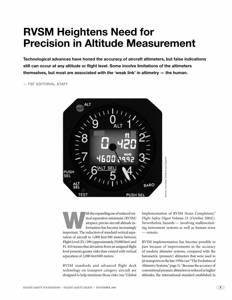
RVSM Heightens Need for Precision in Altitude MeasurementTechnological advances have honed the accuracy of aircraft altimeters, but false indications
still can occur at any altitude or flight level. Some involve limitations of the altimeters
themselves, but most are associated with the ‘weak link’ in altimetry — the human.
— FSF EDITORIAL STAFF
With the expanding use of reduced ver-tical separation minimum (RVSM) airspace, precise aircraft altitude in-formation has become increasingly
important. The reduction of standard vertical sepa-ration of aircraft to 1,000 feet/300 meters between Flight Level (FL) 290 (approximately 29,000 feet) and FL 410 means that deviation from an assigned fl ight level presents greater risks than existed with vertical separation of 2,000 feet/600 meters.
RVSM standards and advanced flight deck technology on transport category aircraft are designed to help minimize those risks (see “Global
Implementation of RVSM Nears Completion,” Flight Safety Digest Volume 23 [October 2004]). Nevertheless, hazards — involving malfunction-ing instrument systems as well as human error — remain.
RVSM implementation has become possible in part because of improvements in the accuracy of modern altimeter systems, compared with the barometric (pressure) altimeters that were used in jet transports in the late 1950s (see “The Evolution of Altimetry Systems,” page 3).1 Because the accuracy of conventional pressure altimeters is reduced at higher altitudes, the international standard established in
Sou
rce:
Inno
vativ
e S
olut
ions
and
Sup
port

2 FLIGHT SAFETY FOUNDATION • FLIGHT SAFETY DIGEST • NOVEMBER 2004
P R E C I S I O N I N A L T I T U D E M E A S U R E M E N T
1960 was for vertical separation of 2,000 feet between aircraft operated above FL 290.
As technological advances in al-timeters, autopilots and altitude-alerting systems led to more precision in measuring and maintaining alti-tude, the International Civil Aviation Organization (ICAO) determined, after a series of studies in the 1980s, that RVSM was technically feasible and developed a manual for RVSM implementation.2 Further guidance for aircraft operators is contained in two ICAO-approved documents: European Joint Aviation Authorities Leaflet No. 63 and U.S. Federal
Aviation Administration Document 91-RVSM.4
Included in these documents are minimum equip-ment requirements for RVSM operations:
• Two independent altitude-measurement systems;
• One secondary surveillance radar transpon-der with an altitude-reporting system that can be connected to the altitude-measurement system in use for altitude-keeping;
• An altitude-alerting system; and,
• An automatic altitude-control system.
In addition, an ICAO minimum aircraft system performance specification (MASPS) requires that the altimetry systems in RVSM-approved aircraft have a maximum altimeter system er-ror (ASE) of 80 feet/25 meters and that the automatic altitude-control systems must be able to hold altitude within 65 feet/20 meters. (ICAO defi nes ASE as “the difference between the altitude indicated by the altimeter display, assuming a correct altimeter barometric setting, and the pressure altitude corresponding to the undisturbed ambient pressure.”)
The ICAO manual for RVSM implementation says that before fl ight in RVSM airspace, a fl ight crew should conduct a ground check to ensure that the required two main altimeter systems are within the prescribed tolerances.
During fl ight, “generally fl ight crew operating proce-dures in RVSM airspace are no different than those in any other airspace,” the ICAO manual says.
Nevertheless, the manual says, “It is essential that the aircraft be fl own at the cleared fl ight level (CFL). This requires that particular care be taken to ensure that air traffi c control (ATC) clearances are fully understood and complied with. … During cleared transition between [fl ight] levels, the aircraft should not be allowed to overshoot or undershoot the new fl ight level by more than [150 feet/45 meters].”
In addition, fl ight crews should conduct regular hourly cross-checks between the altimeters, and “a minimum of two RVSM MASPS-compliant systems must agree within 60 meters (200 feet). Failure to meet this condition will require that the system be reported as defective and notifi ed to ATC,” the ICAO manual says.
Height-monitoring is another RVSM requirement, and the U.K. Civil Aviation Authority (CAA) said in mid-2004 that height-monitoring had revealed the problem of “ASE drift,” a phenomenon in which, over time, most aircraft begin to fl y lower than their displayed altitude.”5
U.K. CAA’s continuing investigation6 of ASE drift has found that likely causes include changes over time in the performance of air-data computers and erosion of pitot-static probes.
The investigation also has found that ASE can be exacerbated by inadequate operational practices by fl ight crews, especially noncompliance with aircraft operating restrictions contained in the RVSM airworthiness approval.
“In particular, if the approval was based on ad-herence to speed limits, the fl ight crew must be aware of those limits and ensure that the aircraft is operated within the cleared speed envelope,” U.K. CAA said.
In addition, during RVSM operations, both the active autopilot and the operating transponder should be selected to the same altimetry system, “unless there is a systems limitation or functional-ity which makes the requirement unnecessary and is detailed in the AFM [aircraft fl ight manual].”
Continued on page 5

3FLIGHT SAFETY FOUNDATION • FLIGHT SAFETY DIGEST • NOVEMBER 2004
P R E C I S I O N I N A L T I T U D E M E A S U R E M E N T
Altimeters have provided pilots with essential flight information since the development in 1928 of an accurate
barometric (pressure) altimeter.
Altimeters indirectly measure the height of an aircraft above mean sea level or above a ground reference datum by sensing the changes in ambient air pressure that accompany changes in altitude and provide a corresponding altitude reading in feet or meters.
Static air pressure typically is derived from static sources mounted on the sides of the fuselage.
Figure 1 shows how the system typically works in early jet transports. A static line connects the static ports to the altimeter, mounted in an airtight case in which a sealed aneroid barometer reacts to changes in static air pressure. When static air pressure increases, the barometer contracts; when static air pressure decreases, the barometer expands. The movement of the barometer causes movement of height-indicating pointers, which present an altitude indication on the face of the altimeter.1
Also on the face of a conventional barometric altimeter is a barometric scale, calibrated in hectopascals (hPa; millibars) or inches of mercury (in. Hg). The scale can be adjusted by a pilot to the local barometric pressure (e.g., within 100 nautical miles [185 kilometers]) or to standard barometric pressure — 1013.2 hPa or 29.92 in. Hg — as required by applicable regulations.
The system changed as new airplane models were introduced with air data computers and other advanced electronics and digital displays.
Figure 2 (page 4) shows how the system typically works in modern transport category aircraft, in which an air data inertial reference unit (ADIRU) is the primary source for altitude (as well as airspeed and attitude), and the information is displayed on the pilots’ primary flight displays. Pitot and static pressures are measured by air data modules (ADMs) connected to three independent air pressure sources; ADM information is transmitted through data buses to the ADIRU. The ADIRU calculates altitude and airspeed by comparing information from the three sources, and provides a single set of data for both the captain and the first officer. If an
ASI AL T
Verticalgyro
Verticalgyro
CaptainAC power
Staticports
Pitottube
Staticports
Pitottube
First officerAC power
ASI AI AIAL T
Figure 1Typical Flight Instrumentation on Early Jet Transports
AC = Alternating current AI = Attitude indicator ALT = Altimeter ASI = Airspeed indicator
Source: Adapted from Carbaugh, David C. “Erroneous Flight Instrument Information.” In Enhancing Safety in the 21st Century: Proceedings of the 52nd Annual International Air Safety Seminar. Alexandria, Virginia, U.S.: Flight Safety Foundation, 1999.
The Evolution of Altimetry Systems

4 FLIGHT SAFETY FOUNDATION • FLIGHT SAFETY DIGEST • NOVEMBER 2004
P R E C I S I O N I N A L T I T U D E M E A S U R E M E N T
ADIRU fails, an electronic standby altimeter and an electronic standby airspeed indicator receive pitot-static data from standby ADMs.2
The newest systems are “far more accurate” than the altimeters that were installed in early jet transports, said Jim Zachary, president of ZTI, an avionics consulting firm.3
“The old-type altimeters were not corrected for static source error, which is a function of airspeed,” Zachary said. “The pilot would look at the altitude and look at the airspeed and go to some chart and say, ‘OK, I’ve got to do this correction, change my altitude, add 100 feet or 200 feet.’
“That’s all done automatically now. … The new electronic altimeters have an integrated ADM and are connected to pitot (for airspeed) and static pneumatics. All errors are corrected internally. This is extremely important for the new, demanding
requirements for reduced separation of aircraft. … It means that you have an altimeter that’s absolutely correct.” ■
— FSF Editorial Staff
Notes
1. Harris, David. Flight Instruments and Automatic Flight Control Systems. Oxford, England: Blackwell Science, 2004.
2. Carbaugh, Dave; Forsythe, Doug; McIntyre, Melville. “Erroneous Flight Instrument Information.” Boeing Aero No. 8 (October 1999).
3. Zachary, Jim. Telephone interview by Werfelman, Linda. Alexandria, Virginia, U.S. Nov. 12, 2004. Flight Safety Foundation, Alexandria, Virginia, U.S.
Pt
ASIASI
ADIRU
ALT
ALT
RightAIMS
LeftAIMS
PFDPFD
ADM
PTR
ADM
ADM
ADM
Ps
ADM
ADM
StandbyADM
LCDs
SAARU
ADM
Standby
Staticports
Staticports
Pitottube
Pitottubes
Figure 2Typical Flight Instrumentation on Modern, Fly-by-wire Airplanes
ADIRU = Air data inertial reference unit ADM = Air data module AIMS = Airplane information management system ALT = Altimeter ASI = Airspeed indicator LCD = Liquid crystal displayPFD = Primary fl ight display Ps = Static pressure Pt = Total pressure SAARU = Secondary attitude air data reference unit
Source: Adapted from Carbaugh, David C. “Erroneous Flight Instrument Information.” In Enhancing Safety in the 21st Century: Proceedings of the 52nd Annual International Air Safety Seminar. Alexandria, Virginia, U.S.: Flight Safety Foundation, 1999.

5FLIGHT SAFETY FOUNDATION • FLIGHT SAFETY DIGEST • NOVEMBER 2004
P R E C I S I O N I N A L T I T U D E M E A S U R E M E N T
Air Data Computers, Glass-cockpit Displays Improve Accuracy
Despite the findings about ASE drift, the precision of altitude information avail-
able on the fl ight deck has increased in recent years because of the development of the air data computer (ADC), air data inertial reference unit (ADIRU) and digital displays. Modern systems may include an ADIRU that receives informa-tion from air data modules (ADMs) connected to the airplane’s pitot probes and static pressure sources; the unit incorporates the best of that information (rejecting data that are incompat-ible with data produced by the other sources) to provide a single set of data to both pilots. Other standby ADMs provide information for standby fl ight instruments.7,8
Improvements in the accuracy of modern altim-eter systems, however, have not eliminated the possibility of critical altimeter-setting problems, which often result from human error.
Several factors related to barometric altimeters often have been associated with a fl ight crew’s loss of vertical situational awareness, which in turn has been associated with many controlled-fl ight-into-terrain (CFIT) accidents.9,10 These factors include confusion resulting from the use of different altitude and height reference systems and different altimeter-setting units of measurement.
In 1994, the Flight Safety Foundation (FSF) CFIT Task Force said, “Flight crew training is now used as a means of solving this problem, but consid-eration should be given to discontinuing the use of some altimeter designs and standardizing the use of altitude and height reference systems and altimeter-setting units of measurement.” Many of the Foundation’s recommendations have since been endorsed by ICAO, civil aviation authorities and aircraft operators in many countries.
ICAO has recommended procedures for provid-ing adequate vertical separation between aircraft and adequate terrain clearance, including what units should be used to measure air pressure, what settings should be used to display the measure-ment and when during a flight the settings
should be changed; nevertheless, many varia-tions are used by civil aviation authorities in different countries (see “ICAO Prescribes Basic Principles for Vertical Separation, Terrain Clearance,” page 6).11
Capt. David C. Carbaugh, chief pilot, fl ight opera-tions safety, Boeing Commercial Airplanes, said that, despite technological advances, “a human still has to set the altimeter, and it’ll display what it’s asked to display; if you ask it to display the wrong thing, that’s what it will display. It’s well-documented that the human is the weak link in altimetry.”12
Altimeter mis-setting has been identified as one of the top six causal factors associated with level busts,13 which are defi ned by the European Organisation for Safety of Air Navigation (Eurocontrol) as unauthorized vertical devia-tions from an ATC fl ight clearance of more than 300 feet outside RVSM airspace and more than 200 feet within RVSM airspace.14
“Level busts, or altitude deviations, are a poten-tially serious aviation hazard and occur when an aircraft fails to fl y at the level required for safe separation,” Eurocontrol said in the “Level Bust Briefi ng Notes,” a set of discussion papers included in the European Air Traffi c Management Level Bust Toolkit. (The tool kit is designed to raise awareness of the level bust issue among aircraft operators and air navigation service providers and to help them develop strategies to reduce level busts. Fourteen briefi ng notes are a fundamental part of the tool kit.)
“When … RVSM applies, the po-tential for a dangerous situation to arise is increased. This operational hazard may result in serious harm, either from a midair collision or from collision with the ground (CFIT),” the briefi ng notes said.
Studies have shown that an average of one level bust per commercial aircraft occurs each year, that one European country reports more than 500 level busts a year and that one major European airline reported 498 level busts from July 2000 to June 2002.15

6 FLIGHT SAFETY FOUNDATION • FLIGHT SAFETY DIGEST • NOVEMBER 2004
P R E C I S I O N I N A L T I T U D E M E A S U R E M E N T
ICAO Prescribes Basic Principles for Vertical Separation, Terrain Clearance
The International Civil Aviation Organization (ICAO) recommends a method of providing adequate
vertical separation between aircraft and adequate terrain clearance, according to the following principles:1
• “During flight, when at or below a fixed altitude called the transition altitude, an aircraft is flown at alti-tudes determined from an altimeter set to sea level pressure (QNH)2 and its vertical position is expressed in terms of altitude;
• “During flight, above the transition altitude, an aircraft is flown along surfaces of constant atmospheric pressure, based on an altimeter setting of 1013.2 hectopascals [29.92 inches of mercury], and throughout this phase of a flight, the vertical position of an aircraft is expressed in terms of flight levels. Where no transition altitude has been established for the area, aircraft in the en route phase shall be flown at a flight level;
• “The change in reference from altitude to flight levels, and vice versa, is made, when climbing, at the transi-tion altitude and, when descending, at the transition level;
• “The adequacy of terrain clearance during any phase of a flight may be maintained in any of several
ways, depending upon the facilities available in a particular area, the recommended methods in the order of preference being:
– “The use of current QNH reports from an adequate network of QNH reporting stations;
– “The use of such QNH reports as are available, combined with other meteorological information such as forecast lowest mean sea level pressure for the route or portions thereof; and,
– “Where relevant current informa-tion is not available, the use of values of the lowest altitudes of flight levels, derived from clima-tological data; and,
• “During the approach to land, ter-rain clearance may be determined by using the QNH altimeter setting (giv-ing altitude) or, under specified cir-cumstances … a QFE3 setting (giving height above the QFE datum).”
ICAO says that these procedures provide “sufficient flexibility to permit variation in detail[ed] procedures which may be required to account for local conditions without deviating from the basic procedures.” ■
— FSF Editorial Staff
Notes
1. International Civil Aviation Organization. Procedures for Air Navigation Services. Aircraft Operations, Volume 1: Flight Procedures. Part VI, Altimeter Setting Procedures.
2. QNH is the altimeter setting provided by air traffic control or reported by a specific station and takes into account height above sea level with corrections for local atmospheric pressure. On the ground, the QNH altimeter setting results in an indication of actual elevation above sea level; in the air, the QNH altimeter setting results in an indication of the true height above sea level, without adjustment for nonstandard temperature.
3. QFE is an altimeter setting corrected for actual height above sea level and local pressure variations; a QFE altimeter setting applies to a specific ground-reference datum. On the ground, a correct QFE altimeter setting results in an indication of zero elevation; in the air, the QFE setting results in an indication of height above the ground reference datum.
Tzvetomir Blajev, coordinator of safety im-provement initiatives, Safety Enhancement Business Division, Directorate of Air Traffi c Management Programmes, Eurocontrol, said that data are not suffi cient to evaluate incorrect altimeter settings in European RVSM airspace.16
Nevertheless, Blajev said, “An incorrect altimeter setting is of concern to us. … Some of the 21 recommendations in the Level Bust Toolkit are designed to fi ght the risk of errors in altimeter settings. One
specifi cally is targeted at this: ‘Ensure clear procedures for altimeter cross-checking and approaching level calls.’ To support the implementation of this recommendation, we have developed a briefi ng note.”
Different Standards Lead to Confusion
Some altimeter-setting errors that oc-cur during international fl ights have
been attributed to the fact that not all civil aviation authorities have the same altimeter-setting rules and requirements.
C. Donald Bateman, chief engineer, fl ight safety systems, Honeywell, said, “We have so many different altimeter-setting standards. Obviously, there’s a good chance we’re go-ing to have errors, and we’ve had them.”17
For example, different altimeter-setting practices involving QFE and QNH can cause confusion.

7FLIGHT SAFETY FOUNDATION • FLIGHT SAFETY DIGEST • NOVEMBER 2004
P R E C I S I O N I N A L T I T U D E M E A S U R E M E N T
QFE is an altimeter setting corrected for actual height above sea level and local pressure variations; a QFE altim-eter setting applies to a specifi c ground-reference datum. On the ground, a cor-rect QFE setting results in an indication of zero elevation; in the air, the QFE setting results in an indication of height above the ground-reference datum.
QNH is the altimeter setting provided by ATC or reported by a specifi c station and takes into account height above sea level with corrections for local atmospheric pressure. On the ground, the QNH al-timeter setting results in an indication of actual elevation above sea level; in the air, the QNH altimeter setting results in an indication of the true height above sea level, without adjustment for nonstan-dard temperature.
(Another “Q code” is QNE, which refers to the standard pressure altimeter setting of 1013.2 hectopascals [hPa], or 29.92 inches of mercury [in. Hg].)
Some operators require fl ight crews to set the altimeter to QFE in areas where QNH is used by ATC and by most other operators.
The FSF Approach-and-landing Accident Reduction (ALAR) Task Force said that us-ing QNH has two advantages: “eliminating the need to change the altimeter setting during operations below the transition altitude/fl ight level” and eliminating “the need to change the altimeter setting during a missed approach.” (Such a change usu-ally is required when QFE is used.)18
Many civil aviation authorities use hecto-pascals (millibars), to measure baromet-ric pressure; others use inches of mercury (Figure 1); if a pilot confuses the two and mis-sets the altimeter, the result can mean that the aircraft is hundreds of feet lower (or higher) than the indicated altitude (Figure 2; Figure 3, page 8).19
The ICAO standard is for altimeter set-tings to be given in hectopascals, and in
31.5
31.0
30.5
30.0
29.5
29.0
28.5
Inches ofmercury
Hectopascals(millibars)
Inches ofmercury
Hectopascals(millibars)
965
970
980
990
1000
1010
1020
1030
1040
1050
1060
1065
Figure 1Altimeter-setting Conversion Table
Source: U.S. Government Printing Offi ce
Figure 2Pressure/Altitude Conversion Table
Source: U.S. Government Printing Offi ce
31
30
29
28
27
26
25
24
23
22
21
20
19
18
17
16
15
14
13
12 400
500
600
700
800
900
1000
1050
Inches ofmercury
Hectopascals(millibars)
Hundredsof feet*
Inches ofmercury
Hectopascals(millibars)
Hundredsof feet*
0
10
20
30
40
50
60
70
80
90
100
110
120
130
140
150
160
170
180
190
200
210
220
230
-10
*Standard Atmosphere

8 FLIGHT SAFETY FOUNDATION • FLIGHT SAFETY DIGEST • NOVEMBER 2004
P R E C I S I O N I N A L T I T U D E M E A S U R E M E N T
1994, the Foundation recommended that all civil aviation authorities adopt hecto-pascals for altimeter settings to eliminate the “avoidable hazard of mis-setting the altimeter.”20
In 2000, the Foundation repeated the recommendation in its “ALAR Briefi ng Notes”:
When in. Hg is used for the altimeter setting, unusual barometric pressures, such as a 28.XX in. Hg (low pressure) or a 30.XX in. Hg (high pressure), may go undetected when listening to the … ATIS [automatic terminal information service] or ATC, result-ing in a more usual 29.XX altimeter setting being set.
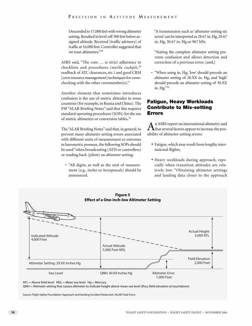
Figure [4, page 9] and Figure [5, page 10] show that a 1.00 in. Hg discrepancy in the altimeter setting results in a 1,000-foot error in the indicated altitude.
In Figure [4], QNH is an unusually low 28.XX in. Hg, but the altimeter was set mistakenly to a more usual 29.XX in. Hg, resulting in the true
altitude (i.e., the aircraft’s actual height above mean sea level) being 1,000 feet lower than indicated.
In Figure [5], QNH is an unusually high 30.XX in. Hg, but the altimeter was set mistakenly to a more usual 29.XX in. Hg, resulting in the true altitude being 1,000 feet higher than indicated.21
Numerous reports about these problems have been submitted to the U.S. National Aeronautics and Space Administration (NASA) Aviation Safety Reporting System (ASRS),22 including the following:
• The captain of an air carrier pas-senger flight said that during de-scent to Frankfurt, Germany, “the altimeters were incorrectly set at 29.99 in. Hg instead of 999 hPa, resulting in Frankfurt approach control issuing an altitude alert. The reason I believe this happened is that the ATIS was copied by the relief pilot using three digits with a decimal point. Since Frankfurt normally issues both hectopascals and inches of mercury on the ATIS,
I incorrectly assumed that the deci-mal denoted the inches of mercury scale and announced ‘2999’ and set my altimeter. The first officer did the same. … In the future, I will insist that all ATIS information is to be copied, and particularly both altimeter settings.
“ … Safety would also be greatly enhanced if ICAO standards were complied with by the controllers (i.e., stating the units when giving the altimeter setting). … I believe this could happen to almost any pilot, given similar circumstances. I feel that stating units by all con-cerned would eliminate most of the problem”;23
• Another pilot said that at the end of a long overwater flight, “approach control gave the altimeter as 998 hPa. I read back 29.98 [in. Hg]. [The] approach controller repeated his original statement. Forgetting that our altimeters have settings for millibars and hectopascals (which I had only used once in my career, and that was six months ago), I
Sea Level
Indicated Altitude4,000 Feet
Field Elevation2,000 Feet
ActualHeight
1,360 AFL
Altimeter Setting: 29.91 Inches Hg (1012 hPa)
QNH: 991 hPa
Actual Altitude3,360 Feet MSL
Altimeter Error640 Feet
Figure 3Effect of an Altimeter Mis-set to Inches, Rather Than Hectopascals
AFL = Above fi eld level MSL = Mean sea level Hg = Mercury hPa = HectopascalsQNH = Altimeter setting that causes altimeter to indicate height above mean sea level (thus, fi eld elevation at touchdown)
Source: Flight Safety Foundation Approach-and-landing Accident Reduction (ALAR) Task Force

9FLIGHT SAFETY FOUNDATION • FLIGHT SAFETY DIGEST • NOVEMBER 2004
P R E C I S I O N I N A L T I T U D E M E A S U R E M E N T
asked where the conversion chart was. ‘Old hand’ captain told me that approach [control] meant 29.98 [in. Hg]. Assuming that he knew what he was doing, I believed him. We were a bit low on a ragged approach, and I knew we were awfully close to some of the hills that dot the area … but it was not until we landed and our altimeters read 500 feet low that I realized what had happened.”24
Transition Altitudes Vary
Civil aviation authorities worldwide have established transition alti-
tudes at which fl ight crews switch their altimeter settings between the standard altimeter setting for fl ights at or above the transition altitude and the altimeter setting being reported by the nearest reporting station for fl ights below the transition altitude. The designated tran-sition altitude varies from 3,000 feet in Buenos Aires, Argentina, to 18,000 feet in North America.25 Transition altitudes can be specifi ed for entire countries or for smaller areas, such as individual airports; in some jurisdictions, the
transition altitude varies, depending on QNH.
NASA said that numerous ASRS reports have been submitted involving altimeter mis-setting events at transition altitudes. The reports included the following:
• A flight crew on an air carrier cargo flight in Europe said that they forgot to reset their altimeters at the un-familiar transition altitude of 4,500 feet. “Climbing to FL 60 … we were task-saturated flying the standard instrument departure, reconfigur-ing flaps and slats, resetting naviga-tion receivers and course settings, resetting engine anti-ice, etc. The crew missed resetting the Kollsman [barometric altimeter] window to 29.92 [in. Hg] at 4,500 feet MSL [above mean sea level] and leveled off at FL 60 indicated altitude with a Kollsman setting of 28.88 [in. Hg]. Departure [control] informed us of our error”;26
• A first officer on an air carrier pas-senger flight said, “Due to a distrac-tion from a flight attendant, we
neglected to reset altimeters pass-ing through FL 180 from 29.92 [in. Hg] to 29.20 [in. Hg]. Extremely low pressure caused us to be at 12,200 feet when we thought we were at 13,000 feet. The controller queried us; we realized our error and climbed to 13,000 feet after resetting the al-timeter. We didn’t accomplish the approach checklist on descent, which would have prevented this”;27
• A first officer on an air carrier cargo flight said, “Received low-altitude warning, pulled up and discovered altimeter … was mis-set. Altimeter was set at 29.84 [in. Hg] and should have been set at 28.84 [in. Hg]. Crew distracted with a [mechanical problem] about the time of altim-eter transition [through FL 180]”;28 and,
• A first officer on an air carrier passen-ger flight said, “Just before we began descent, the flight attendant brought up dinner for both of us at the same time. Started descent as [we] started eating. Because of distraction, we failed to reset altimeters at 18,000 feet.
Sea Level
Indicated Altitude4,000 Feet
Field Elevation2,000 Feet
ActualHeight
1,000 AFL
Altimeter Setting: 29.XX Inches Hg
QNH: 28.XX Inches Hg
Actual Altitude3,000 Feet MSL
Altimeter Error1,000 Feet
Figure 4Effect of a One-inch-high Altimeter Setting
AFL = Above fi eld level MSL = Mean sea level Hg = Mercury QNH = Altimeter setting that causes altimeter to indicate height above mean sea level (thus, fi eld elevation at touchdown)
Source: Flight Safety Foundation Approach-and-landing Accident Reduction (ALAR) Task Force
10 FLIGHT SAFETY FOUNDATION • FLIGHT SAFETY DIGEST • NOVEMBER 2004
P R E C I S I O N I N A L T I T U D E M E A S U R E M E N T
Descended to 17,000 feet with wrong altimeter setting. Resulted in level-off 300 feet below as-signed altitude. Received [traffic advisory] of traffic at 16,000 feet. Controller suggested that we reset altimeters.”29
ASRS said, “The cure … is strict adherence to checklists and procedures (sterile cockpit,30 readback of ATC clearances, etc.) and good CRM [crew resource management] techniques for cross-checking with the other crewmember(s).”
Another element that sometimes introduces confusion is the use of metric altitudes in some countries (for example, in Russia and China). The FSF “ALAR Briefi ng Notes” said that this requires standard operating procedures (SOPs) for the use of metric altimeters or conversion tables.31
The “ALAR Briefi ng Notes” said that, in general, to prevent many altimeter-setting errors associated with different units of measurement or extremes in barometric pressure, the following SOPs should be used “when broadcasting (ATIS or controllers) or reading back (pilots) an altimeter setting:
• “All digits, as well as the unit of measure-ment (e.g., inches or hectopascals) should be announced.
“A transmission such as ‘altimeter setting six seven’ can be interpreted as 28.67 in. Hg, 29.67 in. Hg, 30.67 in. Hg or 967 hPa.
“Stating the complete altimeter setting pre-vents confusion and allows detection and correction of a previous error; [and,]
• “When using in. Hg, ‘low’ should precede an altimeter setting of 28.XX in. Hg, and ‘high’ should precede an altimeter setting of 30.XX in. Hg.”32
Fatigue, Heavy Workloads Contribute to Mis-setting Errors
An ASRS report on international altimetry said that several factors appear to increase the pos-
sibility of altimeter-setting errors:
• Fatigue, which may result from lengthy inter-national flights;
• Heavy workloads during approach, espe-cially when transition altitudes are rela-tively low. “Obtaining altimeter settings and landing data closer to the approach
Sea Level
Indicated Altitude4,000 Feet
Field Elevation2,000 Feet
Actual Height3,000 AFL
Altimeter Setting: 29.XX Inches Hg
QNH: 30.XX Inches Hg
Actual Altitude5,000 Feet MSL
Altimeter Error1,000 Feet
Figure 5Effect of a One-inch-low Altimeter Setting
AFL = Above fi eld level MSL = Mean sea level Hg = Mercury QNH = Altimeter setting that causes altimeter to indicate height above mean sea level (thus, fi eld elevation at touchdown)
Source: Flight Safety Foundation Approach-and-landing Accident Reduction (ALAR) Task Force
11FLIGHT SAFETY FOUNDATION • FLIGHT SAFETY DIGEST • NOVEMBER 2004
P R E C I S I O N I N A L T I T U D E M E A S U R E M E N T
segment complicates the task of preparing data for landing at the very time the flight crew may be most fatigued”;
• Language difficulties, including “rapid deliv-ery of clearances … , unfamiliar accents and contraction of hPa (hectopascals) or mb (mil-libars). … Other flight crews communicating in their native [languages] contribute to a lack of awareness of what other traffic is doing”;
• Communication procedures in which one person receives approach and landing infor-mation and conveys the information to the rest of the flight crew. This procedure “means that a misconception or misunderstanding is less likely to be detected until too late”; and,
• Cockpit management, which “often [pro-vides] inadequate crew briefing for ap-proach and landing, with no mention of how the altimeter setting will be expressed — that is, [inches of mercury], [millibars] or [hectopascals]. Flight crews also may not ad-equately review approach charts for informa-tion. Some airlines do not provide the second officer with approach [charts]; unless he or she makes an extra effort to look at one of the pilot’s charts, the altimeter-setting standard may be unknown.” (In addition, some airlines provide only one set of approach charts for the captain and first officer to share.)33
The ASRS report contained several recommenda-tions, including having each fl ight crewmember “pay particular attention” during the review of approach charts before the descent to whether altimeter settings will be given in inches, milli-bars or hectopascals; ensuring that the approach briefi ng includes mention of how the altimeter setting will be expressed; enabling more than one fl ight crewmember to hear ATC clearances and ATIS messages; and complying with proper crew coordination standards by cross-checking other crewmembers for accurate communication and procedures.
‘Odd’ Altimeter Settings Should Prompt Questions
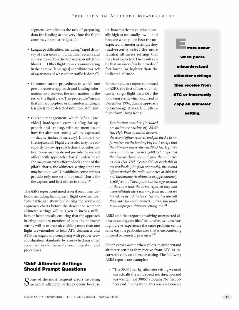
Some of the most frequent errors involving incorrect altimeter settings occur because
the barometric pressure is unusu-ally high or unusually low — and because when pilots hear the un-expected altimeter settings, they inadvertently select the more familiar altimeter settings that they had expected. The result can be that an aircraft is hundreds of feet lower (or higher) than the indicated altitude.
For example, in a report submitted to ASRS, the fi rst offi cer of an air carrier cargo fl ight described the following event, which occurred in December 1994, during approach to Anchorage, Alaska, U.S., after a fl ight from Hong Kong:
Destination weather [included an altimeter setting of] 28.83 [in. Hg]. Prior to initial descent, the second offi cer received and put the ATIS in-formation on the landing bug card, except that the altimeter was written as 29.83 [in. Hg]. We were initially cleared to 13,000 feet. I repeated the descent clearance and gave the altimeter as 29.83 [in. Hg]. Center did not catch this in my readback. [On fi nal approach], the second offi cer noticed the radio altimeter at 800 feet and the barometric altimeter at approximately 1,800 feet. … The captain started a go-around at the same time the tower reported they had a low-altitude alert warning from us. ... As we taxied, we heard the tower tell another aircraft they had a low-altitude alert. … Was this [due] to an improper altimeter setting, too?34
ASRS said that reports involving unexpected al-timeter settings are fi led “in bunches, as numerous fl ight crews experience the same problem on the same day in a particular area that is encountering unusual barometric pressures.”35
Other errors occur when pilots misunderstand altimeter settings they receive from ATC or in-correctly copy an altimeter setting. The following ASRS reports are examples:
• “The 30.06 [in. Hg] altimeter setting we used was actually the wind speed and direction and was written [as] 3006,” a Boeing 767 first of-ficer said. “In my mind, this was a reasonable

12 FLIGHT SAFETY FOUNDATION • FLIGHT SAFETY DIGEST • NOVEMBER 2004
P R E C I S I O N I N A L T I T U D E M E A S U R E M E N T
altimeter setting. The ATIS setting was actu-ally 29.54 [in. Hg]”;36
• “The altimeter [setting] was 28.84 [in. Hg],” the second officer on a cargo flight said. “I remember enlarging the 8s with two circles on top of each other, thinking this would be sufficient in drawing attention to the low al-timeter setting. The next crew after our flight found the altimeter to be set at 29.84 [in. Hg] instead of the actual 28.84 [in. Hg] setting”;37 and,
• “The pilot not flying understood [the] ATIS recording to state altimeter setting to be 29.99 [in. Hg] when actually the setting was 29.29 [in. Hg],” the captain of an MD-83 passenger flight said. He suggested that “slower, more pronounced ATIS recordings” might help avoid similar problems.38
Some controllers emphasize the altimeter setting when the barometric pressure is unusually low, but typically this is not a requirement.
Altimeter Design Can Cause Mis-reading of Indicator
Sometimes, even though the altimeter setting has been selected correctly, errors occur in
reading an altimeter. In 1994, the Foundation in-cluded among its recommendations to reduce the worldwide CFIT accident rate a request that ICAO issue a warning against the use of three-pointer altimeters and drum-pointer altimeters.
“The misreading of these types of altimeters is well documented,” the Foundation said.39
In 1998, ICAO adopted amendments to its standards and recommended practices to prohibit the use of these altimeters in commercial aircraft operated under instrument flight rules (IFR), citing a “long history of misreadings.”40
Before the adoption of those amendments, a Nov. 14, 1990, ac-cident occurred in which an Alitalia McDonnell Douglas DC-9-32 struck
a mountain during a night instrument landing system (ILS) approach to Kloten Airport in Zurich, Switzerland. The accident report said that, among other problems, the fl ight crew “probably misread the [drum-pointer] altimeter during the approach and hence did not realize that the aircraft was considerably below the glide path.” The airplane was destroyed, and all 46 people in the airplane were killed.41
The report said that drum-pointer altimeters are “less easy to read correctly, especially during periods of high workload” than other altimeters. “A quick look after being distracted can usually induce a reading 1,000 feet off, if the barrel drum is halfway between thousands,” the report said.
In a report submitted to ASRS, the single pilot of a small corporate airplane described a similar altimeter-reading problem:
I was assigned 5,000 feet [by ATC]. I thought I was getting ready to level off at 5,000 feet, and departure [control] asked what altitude I was climbing to. I realized I was at 5,700 feet instead of 4,700 feet. This altimeter [makes it] diffi cult to tell sometimes what the altitude is because the 1,000-foot indicators are in a window to the left. No excuse. I simply looked at it wrong. I know it is diffi cult to read, so I should have been more alert.42
In some incidents, especially when barometric pressure is fl uctuating, fl ight crews operate with-out the most current altimeter settings.
For example, the crew of an American Airlines McDonnell Douglas MD-83 was conducting a very-high-frequency omnidirectional radio (VOR) approach to Bradley International Airport in Windsor Locks, Connecticut, U.S., in night in-strument meteorological conditions (IMC) on Nov. 12, 1995, when the fi rst offi cer glanced at the altimeter and observed that the airplane was below the minimum descent altitude. He told the captain, who was the pilot fl ying. Moments later, the airplane struck trees on a ridge about 2.5 nautical miles (4.6 kilometers) northwest of the approach end of the runway. The captain began a go-around, applying all available power; the airplane struck the localizer antenna array at the end of a safety overrun area, landed on a stopway and rolled down the runway.43

13FLIGHT SAFETY FOUNDATION • FLIGHT SAFETY DIGEST • NOVEMBER 2004
P R E C I S I O N I N A L T I T U D E M E A S U R E M E N T
The airplane received minor damage. One pas-senger received minor injuries; the 77 other people in the airplane were not injured.
When the accident occurred, the indicated alti-tude on the altimeter, using the QFE method, was “about 76 feet too high … resulting in the airplane being 76 feet lower than indicated on the primary altimeters,” the U.S. National Transportation Safety Board said in the fi nal report on the ac-cident. The report said that the probable cause of the accident was “the fl ight crew’s failure to maintain the required minimum descent altitude until the required visual references identifi able with the runway were in sight.” Contributing fac-tors were “the failure of the … approach controller to furnish the fl ight crew with a current altimeter setting, and the fl ight crew’s failure to ask for a more current setting.”
Occasionally, in remote areas, fl ights are con-ducted far from weather-reporting stations. Rarely, the altimeter setting provided by ATC is inaccurate.
The pilot of a small business airplane said that, as he was flying his airplane near Lake Michigan, U.S., at an indicated altitude of 17,000 feet, ATC “reported my altitude encoder indicated 16,000 feet on the readout. I had departed [un-der visual flight rules] and picked up my IFR clearance at about 4,000 feet. … I had set the [altimeter setting] as provided by [ATC] when clearance was provided. I was approaching a cold front, which was lying north to south over Lake Michigan. I asked for an altimeter setting. The setting provided was one inch lower than the previously provided setting (about 100 nautical miles [185 kilometers] earlier). I reset my altimeter. … After the reset, my altimeter now indicated 16,000 feet … The problem was evidently a very steep pressure gradient behind the cold front.”44
In 1997, ASRS reviewed its database, as well as accident reports and incident reports of the Canadian Aviation Safety Board (predecessor of the Transportation Safety Board of Canada), and found that most altimeter mis-setting incidents that occurred during periods of extremely low barometric pressure occurred in very cold loca-tions or in areas known for severe weather and unusual frontal systems. A number of reports were
fi led from northern Europe, includ-ing Brussels, Belgium; Copenhagen, Denmark; Frankfurt, Germany; Keflavik, Iceland; and Moscow, Russia.45
Temperature Errors Sometimes Are Overlooked
Just as pilots adjust the altimeter settings for nonstandard air pres-
sure, a correction also is required — in some situations — for non-standard air temperature. When the air temperature is warmer than the standard tem-perature for a specifi c height in the atmosphere, the true altitude is higher than the altitude indi-cated on the altimeter. When the air temperature is colder than the standard temperature, the true altitude is lower than the indicated altitude. Moreover, in extremely cold temperatures, the true altitude may be several hundred feet lower (Figure 6, page 14).
ICAO says that when the ambient temperature on the surface is “much lower than that predicted by the standard atmosphere,” a correction must be made, and the calculated minimum safe altitudes must be increased accordingly.
“In such conditions, an approximate correction is 4 percent height increase for every 10 degrees Celsius (C) below the standard temperature, as measured at the altimeter-setting source,” ICAO says. “This is safe for all altimeter-setting source altitudes for temperatures above minus 15 degrees C [fi ve degrees Fahrenheit (F)].”46
ICAO says that for colder temperatures, temperature-correction tables should be used.
ICAO’s temperature-correction table shows, for example, that if the ambient temperature on the surface is minus 20 degrees C (minus 4 degrees F), and the airplane is being fl own 1,000 feet above the altimeter-setting source, the pilot should add 140 feet to published procedure altitudes; at 5,000 feet, the pilot should add 710 feet (Table 1, page 15).
Typically, operators should coordinate the han-dling of cold-temperature altitude corrections

14 FLIGHT SAFETY FOUNDATION • FLIGHT SAFETY DIGEST • NOVEMBER 2004
P R E C I S I O N I N A L T I T U D E M E A S U R E M E N T
with ATC facilities for each cold-weather airport or cold-weather route in their system. The opera-tors should confi rm that minimum assigned fl ight altitudes/fl ight levels and radar vectoring provide adequate terrain clearance in the event of the cold-est expected temperatures; should develop cold-weather altitude-correction procedures, including an altitude-correction table; and should determine which procedures or routes have been designed for cold temperatures and can be fl own without altitude corrections.47
The fight crew training manual for Boeing 737-300/400/500 airplanes says that operators “should consider altitude corrections when altimeter errors become appreciable, especially where high terrain and/or obstacles exist near airports in combination with very cold tempera-tures (minus 30 degrees C/minus 22 degrees F, or colder). Further, operators should also consider correcting en route minimum altitudes and/or fl ight levels where terrain clearance is a factor. … For very cold temperatures, when fl ying pub-lished minimum altitudes signifi cantly above the airport, altimeter errors can exceed 1,000 feet,
resulting in potentially unsafe terrain clearance if no corrections are made.”
In one reported occurrence, a McDonnell Douglas MD-80 was fl own to Kelowna, British Columbia, Canada, when the surface temperature in Kelowna was minus 27 degrees C (minus 17 degrees F). The crew received clearance for a nonprecision ap-proach; soon afterward, the crew abandoned the approach and asked ATC for radar vectors for an-other nonprecision approach, fl ew the approach and landed the airplane. Later, fl ight crewmem-bers told other pilots that they had abandoned the fi rst approach after they realized that they had not applied the necessary 800-foot cold-temperature correction to the published procedure-turn altitude of 4,900 feet above fi eld elevation. A ground-proximity warning system (GPWS) terrain warning occurred near a mountain east of the localizer; the airplane fl ew over the mountaintop with a clear-ance of 150 feet.48
Despite the technological advances in aircraft altimetry and airspeed systems, static ports and pitot probes still are required. Blockages in the
Given Atmospheric Pressure(Pressure Altitude)
True Altitude
Low OutsideAir Temperature
High OutsideAir Temperature
IndicatedAltitude
2,000 Feet3,000 Feet
2,000 Feet
1,000 Feet
Standard OutsideAir Temperature
1,560 Feet
−440 Feet
Figure 6Effects of Temperature on True Altitude
Source: Flight Safety Foundation Approach-and-landing Accident Reduction (ALAR) Task Force

15FLIGHT SAFETY FOUNDATION • FLIGHT SAFETY DIGEST • NOVEMBER 2004
P R E C I S I O N I N A L T I T U D E M E A S U R E M E N T
pitot-static system still occur, and accidents can result (see “Technological Advances Haven’t Eliminated Pitot-static System Problems,” page 16).
These blockages most frequently occur while an airplane is on the ground, sometimes because of tape that is placed over static ports during main-tenance and not removed afterward, or because of water that enters and becomes trapped in static lines and then freezes when the airplane is fl own into colder temperatures at higher altitudes. Typically, the problem does not become apparent to the fl ight crew until after takeoff; even then, they may experience considerable confusion about confl icting information available from their fl ight instruments.
Altitude Information Comes From Other Sources
Other systems, including radio altimeters and the geometric altitude component of
terrain awareness and warning systems (TAWS)49 and navigation systems based on the global po-sitioning system (GPS), also provide altitude information.
Radio altimeters, which typically are used below 2,500 feet above ground level during approaches and landings, measure the vertical distance between an aircraft and the ground directly beneath it. They function this way: The radio altimeter’s transmitter beams a radio signal downward; the signal is refl ect-ed by the ground to the radio altimeter’s receiver. The received frequency differs from the transmitted
frequency, and that difference varies according to aircraft height and the time required for the signal to travel from the airplane to the ground and back. The frequency difference is used in calculating the height of the aircraft above the ground.50
The radio altimeter is designed to be accurate, plus or minus one foot, or plus or minus 3 percent of the indicated height above the ground, whichever is larger. Errors can be introduced by refl ections from the landing gear or other parts of the aircraft, uneven terrain and large buildings or trees.
The geometric altitude component of TAWS measures the aircraft’s true altitude and is com-puted by blending “component altitudes,” such as GPS altitude, radio altitude and QNH-corrected barometric altitude; the computation also com-pensates for errors caused by nonstandard air temperatures.
Geometric altitude is included on the TAWS terrain-awareness display to provide the fl ight crew with a reference altitude for the display and for terrain-avoidance alerts — not for vertical navigation.
A study by Honeywell of the effects of including a digital readout of geometric altitude on the ter-rain awareness display resulted in fi ndings that included the following:51
• “An EGPWS [enhanced ground-proxim-ity warning system] that employs geometric altitude as the reference altitude for the
Table 1Cold-temperature Altitude Correction Chart
Airport temperature (degrees Celsius/Fahrenheit)
Height above the elevation of the altimeter setting source (feet)
200 300 400 500 600 700 800 900 1,000 1,500 2,000 3,000 4,000 5,000
0/32 20 20 30 30 40 40 50 50 60 90 120 170 230 280
-10/14 20 30 40 50 60 70 80 90 100 150 200 290 390 490
-20/-4 30 50 60 70 90 100 120 130 140 210 280 420 570 710
-30/-22 40 60 80 100 120 140 150 170 190 280 380 570 760 950
-40/-40 50 80 100 120 150 170 190 220 240 360 480 720 970 1,210
-50/-58 60 90 120 150 180 210 240 270 300 450 590 890 1,190 1,500
Source: International Civil Aviation Organization
Continued on page 19

16 FLIGHT SAFETY FOUNDATION • FLIGHT SAFETY DIGEST • NOVEMBER 2004
P R E C I S I O N I N A L T I T U D E M E A S U R E M E N T
Technological Advances Haven’t Eliminated Pitot-static System Problems
Despite many technological advances that have led to the development of aircraft systems capable of precise
altitude and airspeed measurements, conventional pressure altimeters and airspeed indicators depend on simple static ports and pitot probes to function correctly. Pitot-static system problems continue to occur and — rarely — become factors in accidents.
“The fact that these accidents occur infrequently can contribute to the ‘startle’ factor [that] flight crews experience, leaving them uncertain about how to respond to the anomaly,” said Capt. David C. Carbaugh, chief pilot, flight operations safety, Boeing Commercial Airplanes.1
One such accident involved an Aeroperu Boeing 757-200 that struck the Pacific Ocean off the coast of Lima, Peru, on Oct. 2, 1996, about 30 minutes after takeoff from Jorge Chavez International Airport in Lima on a night flight to Santiago, Chile. The airplane was destroyed, and all 70 people in the airplane were killed.2 The flight crew had realized immediately after liftoff that their altimeters and airspeed indicators were not providing correct information and had declared an emergency, but they were unable to diagnose the problem and to safely land the airplane.
The final report by the Peruvian General Director of Air Transport Commission of Accident Investigations said that the probable cause of the accident was adhesive tape that was not removed from the static ports after maintenance; the captain did not observe the tape during his walk-around preflight inspection.
The report said that during the takeoff roll, airspeed indications and altitude indications were normal; afterward, however, altimeter indications increased too slowly, and the indicated airspeed (IAS) was too slow. A wind shear warning was activated three times, although wind was relatively calm and there was no
significant weather. The ground-proximity warning system repeatedly sounded warnings of “TOO LOW TERRAIN” and “SINK RATE.”
About one minute before the airplane struck the water, as the “TOO LOW TERRAIN” warning sounded, there was no reaction from the crew, who believed an altimeter indication that the airplane was at 9,700 feet.
The report said that the cockpit voice recorder showed that the captain was “confused in his reactions … and [hesitant] with his commands,” while the first officer displayed “equivalent confusion.” Neither pilot identified the cause of the problem.
Erroneous airspeed indications have been cited in several accidents, including a Feb. 6, 1996, accident in which a B-757-200 struck the Caribbean Sea off the northern coast of the Dominican Republic about five minutes after takeoff from Gregorio Luperon International Airport in Puerto Plata for a flight to Frankfurt, Germany. The airplane — which was operated by Birgenair, a charter company in Istanbul, Turkey, for Alas Nacionales, a Dominican airline — was destroyed, and all 189 occupants were killed.3
In the final report, the Dominican Junta Investigadora de Accidentes Aéreos said that the probable cause of the accident was “the failure on the part of the flight crew to recognize the activation of the stick shaker as an imminent warning of [an] aerodynamic stall and their failure to execute proper procedures for recovery [from] the control loss.”
The report said, “Before activation of the stick shaker, confusion of the flight crew occurred due to the erroneous indication of an increase in airspeed [on the captain’s airspeed indicator] and a subsequent overspeed warning.”
The erroneous airspeed indication and the erroneous overspeed warning resulted
from an obstruction of the airplane’s upper-left pitot tube.
The report said that the airplane had not been flown for 20 days before the accident and that, during that time, routine maintenance had been performed, including an inspection and ground test of the engines. Investigators believed that engine covers and pitot covers were not installed before or after the ground test.
During the takeoff roll, the captain determined that his airspeed indicator was not working; four other sources of airspeed information were available, and he continued the takeoff “contrary to the established procedures,” the report said.
During climbout, the crew decided that the captain’s airspeed indicator and the first officer’s airspeed indicator were providing incorrect indications and that the alternate airspeed indicator was providing correct information. Nevertheless, none of the three flight crewmembers (the captain, the first officer and a relief captain) suggested “the appropriate course of action to compare the indications or to switch the instrument selector [to the alternate source] to derive airspeed information from the [first officer’s air data computer] and its pitot system,” the report said.
The wreckage of the airplane was not recovered, and the cause of the pitot-system obstruction was not determined, but the report said that the obstruction likely resulted from “mud and/or debris from a small insect that was introduced in the pitot tube during the time the aircraft was on the ground in Puerto Plata.”
Pitot-static System Problems Have Many Causes
Other aircraft accident reports and incident reports have identified numerous causes of malfunctions in static ports and pitot probes, including
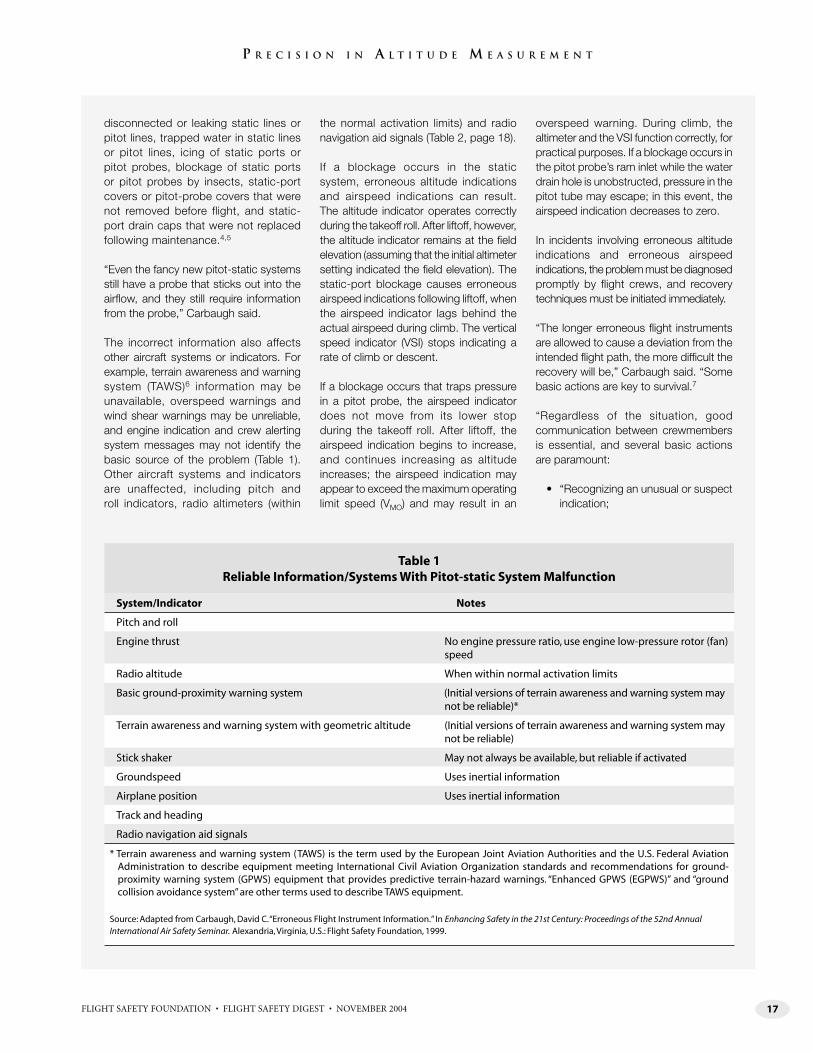
17FLIGHT SAFETY FOUNDATION • FLIGHT SAFETY DIGEST • NOVEMBER 2004
P R E C I S I O N I N A L T I T U D E M E A S U R E M E N T
disconnected or leaking static lines or pitot lines, trapped water in static lines or pitot lines, icing of static ports or pitot probes, blockage of static ports or pitot probes by insects, static-port covers or pitot-probe covers that were not removed before flight, and static-port drain caps that were not replaced following maintenance.4,5
“Even the fancy new pitot-static systems still have a probe that sticks out into the airflow, and they still require information from the probe,” Carbaugh said.
The incorrect information also affects other aircraft systems or indicators. For example, terrain awareness and warning system (TAWS)6 information may be unavailable, overspeed warnings and wind shear warnings may be unreliable, and engine indication and crew alerting system messages may not identify the basic source of the problem (Table 1). Other aircraft systems and indicators are unaffected, including pitch and roll indicators, radio altimeters (within
the normal activation limits) and radio navigation aid signals (Table 2, page 18).
If a blockage occurs in the static system, erroneous altitude indications and airspeed indications can result. The altitude indicator operates correctly during the takeoff roll. After liftoff, however, the altitude indicator remains at the field elevation (assuming that the initial altimeter setting indicated the field elevation). The static-port blockage causes erroneous airspeed indications following liftoff, when the airspeed indicator lags behind the actual airspeed during climb. The vertical speed indicator (VSI) stops indicating a rate of climb or descent.
If a blockage occurs that traps pressure in a pitot probe, the airspeed indicator does not move from its lower stop during the takeoff roll. After liftoff, the airspeed indication begins to increase, and continues increasing as altitude increases; the airspeed indication may appear to exceed the maximum operating limit speed (VMO) and may result in an
overspeed warning. During climb, the altimeter and the VSI function correctly, for practical purposes. If a blockage occurs in the pitot probe’s ram inlet while the water drain hole is unobstructed, pressure in the pitot tube may escape; in this event, the airspeed indication decreases to zero.
In incidents involving erroneous altitude indications and erroneous airspeed indications, the problem must be diagnosed promptly by flight crews, and recovery techniques must be initiated immediately.
“The longer erroneous flight instruments are allowed to cause a deviation from the intended flight path, the more difficult the recovery will be,” Carbaugh said. “Some basic actions are key to survival.7
“Regardless of the situation, good communication between crewmembers is essential, and several basic actions are paramount:
• “Recognizing an unusual or suspect indication;
Table 1 Reliable Information/Systems With Pitot-static System Malfunction
System/Indicator Notes
Pitch and roll
Engine thrust No engine pressure ratio, use engine low-pressure rotor (fan) speed
Radio altitude When within normal activation limits
Basic ground-proximity warning system (Initial versions of terrain awareness and warning system may not be reliable)*
Terrain awareness and warning system with geometric altitude (Initial versions of terrain awareness and warning system may not be reliable)
Stick shaker May not always be available, but reliable if activated
Groundspeed Uses inertial information
Airplane position Uses inertial information
Track and heading
Radio navigation aid signals
* Terrain awareness and warning system (TAWS) is the term used by the European Joint Aviation Authorities and the U.S. Federal Aviation Administration to describe equipment meeting International Civil Aviation Organization standards and recommendations for ground-proximity warning system (GPWS) equipment that provides predictive terrain-hazard warnings. “Enhanced GPWS (EGPWS)” and “ground collision avoidance system” are other terms used to describe TAWS equipment.
Source: Adapted from Carbaugh, David C. “Erroneous Flight Instrument Information.” In Enhancing Safety in the 21st Century: Proceedings of the 52nd Annual International Air Safety Seminar. Alexandria, Virginia, U.S.: Flight Safety Foundation, 1999.

18 FLIGHT SAFETY FOUNDATION • FLIGHT SAFETY DIGEST • NOVEMBER 2004
P R E C I S I O N I N A L T I T U D E M E A S U R E M E N T
• “Keeping control of the airplane with basic pitch and power skills;
• “Taking inventory of reliable information;
• “Finding or maintaining favorable flying conditions;
• “Getting assistance from others; [and,]
• “Using checklists.”
The most important action is maintaining “reasonable airplane control” with normal pitch and power settings, he said. “Troubleshooting should be done later.”
In addition, he said, “Do not trust previously suspected instruments, even if they appear to be operating correctly again.”
Michel Trémaud, senior director, safety and security, Airbus Customer Services, said, “Detecting an unreliable airspeed indication presents some traps: All indications may be consistent but equally
unreliable, [and] indications may differ, but attempting to assess the correct indication may be hazardous.8
“Abnormally large indicated-airspeed fluctuations are an obvious attention-getter [and] unusual differences between the captain’s and first officer’s instruments or between IAS and target airspeed may suggest an unreliable airspeed condition. … Flight crew awareness of IAS/pitch/thrust/climb rate characteristics is the most effective clue; that is, IAS increasing with typical climb pitch attitude or IAS decreasing with typical descent pitch attitude would indicate a problem.”
Other signs of unreliable airspeed indications include an unexpected stall warning, unexpected overspeed warning or simultaneous stall warning and overspeed warning; and an unanticipated IAS-aerodynamic noise relationship, Trémaud said.
If a flight crew detects an unreliable airspeed indication, typical procedures
call for achieving short-term flight path control with pitch and power and then conducting procedures discussed in the quick reference handbook for flight control through landing.
“The art and heart of this procedure is to achieve the desired speed by applying a given pitch attitude and a given power/thrust,” Trémaud said. “This procedure is amazingly accurate in reaching the desired speed with a difference of less than five knots. However, applying this procedure with accuracy requires prior training in the simulator.” (This type of simulator training is not included in type-qualification courses but may be included by operators in their recurrent training programs.) ■
— FSF Editorial Staff
Notes
1. Carbaugh, David C. “Erroneous Flight Instrument Information.” In Enhancing Safety in the 21st Century: Proceedings of the 50th
Table 2Unreliable Information/Systems With Pitot-static System Malfunction
System/Indicator Notes
Autopilot
Autothrottles
Airspeed
Altimeter Blocked static system or blocked pitot-static system
Vertical speed
Wind information
Vertical navigation
Terrain awareness and warning system* Initial versions of terrain awareness and warning systems
Overspeed warning
Wind shear warning
Elevator feel
Engine indication and crew alerting system messages May not identify the basic problem
* Terrain awareness and warning system (TAWS) is the term used by the European Joint Aviation Authorities and the U.S. Federal Aviation Administration to describe equipment meeting International Civil Aviation Organization standards and recommendations for ground-proximity warning system (GPWS) equipment that provides predictive terrain-hazard warnings. “Enhanced GPWS (EGPWS)” and “ground collision avoidance system” are other terms used to describe TAWS equipment.
Source: Adapted from Carbaugh, David C. “Erroneous Flight Instrument Information.” In Enhancing Safety in the 21st Century: Proceedings of the 52nd Annual International Air Safety Seminar. Alexandria, Virginia, U.S.: Flight Safety Foundation, 1999.

19FLIGHT SAFETY FOUNDATION • FLIGHT SAFETY DIGEST • NOVEMBER 2004
P R E C I S I O N I N A L T I T U D E M E A S U R E M E N T
Annual International Air Safety Seminar. Alexandria, Virginia, U.S.: Flight Safety Foundation, 1999.
2. Commission of Accident Investigations, General Director of Air Transport, Peru. Final Report: Accident of Boeing 757-200, Operated by an Airliner of Transport of Peru, South America, Aeroperu, Occurred on the Day of October 12, 1996, [actual date was Oct. 2, 1996] Location: Lima, Peru. The original report was written in Spanish; an English translation was distributed by the Air Line Pilots Association, International.
3. FSF Editorial Staff. “Erroneous Airspeed Indications Cited in
Boeing 757 Control Loss.” Accident Prevention Volume 56 (October 1999).
4. Carbaugh, David C. Interviews by Lacagnina, Mark, and Werfelman, Linda. Alexandria, Virginia, U.S., Oct. 24, 2004; Oct. 28, 2004. Flight Safety Foundation, Alexandria, Virginia, U.S. Additional information from Carbaugh, “Erroneous Flight Instrument Information.”
5. Trémaud, Michel. E-mail communication with Werfelman, Linda. Alexandria, Virginia, U.S., Oct. 22–28, 2004. Flight Safety Foundation, Alexandria, Virginia, U.S.
6. Terrain-awareness and warning system (TAWS) is the term used by the European Joint Aviation Authorities and the U.S. Federal Aviation Administration to describe equipment meeting International Civil Aviation Organization standards and recommendations for ground-proximity warning system (GPWS) equipment that provides predictive terrain-hazard warnings; enhanced GPWS and ground collision avoidance system are other terms used to describe TAWS equipment.
7. Carbaugh. “Erroneous Flight Instrument Information.”
8. Trémaud.
terrain display and predictive alerting func-tions leads to an earlier and improved detec-tion rate of an altitude deviation resulting from altimetry-related anomalies;
• “The addition of a digital readout of geomet-ric altitude on the terrain display leads to an earlier and improved detection rate of an altitude deviation resulting from altimetry-related anomalies; [and,]
• “Geometric altitude resulted in better and more consistent pilot decision making fol-lowing the detection of an altitude anomaly — the display of geometric altitude does not negatively impact pilot decision making.”
Ratan Khatwa, Ph.D., manager, flight safety human factors, Honeywell, said that minor differences are to be expected between the geometric-altitude display and the barometric altimeter indication. A significant difference during flight below transition altitude, how-ever, could signal a problem. For example, the flight crew might have inadvertently mis-set the barometric altimeter; the QNH altimeter set-ting might be incorrect or the aircraft might be operating in an area of large differences from standard temperature or standard air pressure; or either the barometric altimeter or the static system might have failed.
Khatwa said that if a signifi cant difference in the displays of geometric altitude and barometric alti-tude occurs in fl ight before the transition altitude, the fl ight crew should comply with the following procedures:
• “Check and confirm all altimeter settings;
• “Cross-check that any other barometric al-timeters in the flight deck are in agreement;
• “Check that all altimeter settings are current and referenced to the landing airport;
• “Request assistance from ATC as necessary;
• “Monitor for significant temperature differ-ences, especially in cold air. Updated weather information should be requested if in doubt; [and,]
• “Ensure that static ports are not iced over or are not partially blocked, and [that] heaters are switched on when below freezing.”
The Honeywell study assigned the 30 participating pilots — all with about 8,000 fl ight hours to 9,000 fl ight hours and experience in using EGPWS — to one of three groups and presented them with sev-eral fl ight scenarios during a simulator session that was designed to evaluate their responses. Of the
20 FLIGHT SAFETY FOUNDATION • FLIGHT SAFETY DIGEST • NOVEMBER 2004
P R E C I S I O N I N A L T I T U D E M E A S U R E M E N T
group of pilots who used a geometric-altitude display and a digital readout of geometric altitude, 97 percent posi-tively detected altitude deviations. Of the group that used a display based on geometric altitude without a geometric-altitude readout, 78 per-cent detected altitude deviations. Of the group that used a display refer-enced only to barometric altitude, 49 percent detected the anomalies.
Evaluations of the pilots’ responses to the fl ight scenarios found that 98
percent of those who used the geometric-altitude display and readout and 96 percent of those who used the geometric-altitude display responded correctly, compared with 78 percent of those who used only barometric altitude.
Pilots from all groups described their confi dence level as “high, with respect to their ability to detect any altitude anomalies and their subsequent de-cision making,” Khatwa said. Nevertheless, pilots using barometric altitude “often failed to detect altitude anomalies, and therefore, in those cases, [their] perceived terrain awareness did not match actual terrain awareness,” he said.
Increased use of geometric altitude is likely, al-though geometric altitude is unlikely to replace barometric altitude in the near future.
“Use of EGPWS geometric altitude would elimi-nate the consequences of an incorrect altimeter setting or the consequences of not correcting the indicated altitude for extreme low outside air temperatures,” said Michel Trémaud, senior di-rector of safety and security for Airbus Customer Services.52
Carbaugh said that increased reliance on geomet-ric altitude computed from satellite data might be a distant goal.
“Pitot tubes and static ports are pretty old tech-nology, prone to insect nests and other things that can mess them up,” he said. “But satellite-based data, geometric altitude, would be a whole dif-ferent world.”
Bateman said that increased use of geometric altitude technology could eliminate many of the
problems connected with pressure altimeters. Nevertheless, he said, “I don’t know how we could get by without pressure altimeters, as that is how the world of aviation fl ies today, with its QNE/QFE/QNH altimeter-setting references, ATC procedures and practices.
“If we could get rid of pressure altimetry and rely on [GPS-based geometric altitude], we could get rid of the possibility of false altimeter readings and common mode errors where the pressure altim-eter can hurt the integrity of the fl ight. However, I believe we cannot guarantee the integrity of GPS everywhere in the world when we have inadvertent interference, or deliberate interference, nor could the United States probably ever get the rest of the world to switch over [to full reliance on GPS-based geometric altitude].”
In recent years, aircraft altimeters and other altitude-measuring devices have become very precise. Nevertheless, false indications still oc-cur. Continuing research into new methods of altitude-measurement and new uses of existing technologies — such as radio altimeters and GPS-based geometric altitude — may lead to con-tinued improvements in the accuracy of altitude-measuring systems. ■
Notes
1. International Civil Aviation Organization (ICAO). Manual on Implementation of a 300 m (1,000 ft) Vertical Separation Minimum Between FL290 and FL410 Inclusive. Document 9574. Second edition — 2002.
2. Ibid.
3. Joint Aviation Authorities (JAA). Guidance Material on the Approval of Aircraft and Operators for Flight in Airspace Above Flight Level 290 Where a 300-meter (1,000-foot) Vertical Separation Minimum Is Applied. Leafl et no. 6, Revision 1. Jan. 10, 1999.
4. U.S. Federal Aviation Administration (FAA). Guidance Material on the Approval of Operations/Aircraft for RVSM Operations. Document No. 91-RVSM. Feb. 20, 2004.
5. U.K. Civil Aviation Authority (CAA) Safety Regulation Group. Flight Operations Department Communication 7/2004. April 28, 2004.
6. Sanders, David. E-mail communication with Werfelman, Linda. Alexandria, Virginia, U.S., Nov. 1, 2004; Nov. 5, 2004. Flight Safety Foundation,

21FLIGHT SAFETY FOUNDATION • FLIGHT SAFETY DIGEST • NOVEMBER 2004
P R E C I S I O N I N A L T I T U D E M E A S U R E M E N T
Alexandria, Virginia, U.S. Sanders, a U.K. CAA press offi cer, said that the investiga-tion is likely to continue for an “extended period.”
7. Honeywell. Air Transport Avionics. <www.cas.Honeywell.com/ats/products/nav.cfm>. Nov. 5, 2004.
8. Carbaugh, David C. “Erroneous Flight Instrument Information.” Boeing Aero No. 23 (July 2003).
9. Flight Safety Foundation (FSF) Controlled-fl ight-into-terrain (CFIT) Task Force. CFIT Education and Training Aid. 1996.
10. CFIT, as defi ned by the FSF CFIT Task Force, occurs when an airworthy aircraft under the control of the fl ight crew is fl own unintentionally into terrain, obstacles or water, usually with no prior awareness by the crew. This type of ac-cident can occur during most phases of fl ight, but CFIT is more common during the approach-and-landing phase, which begins when an airworthy aircraft under the control of the fl ight crew descends below 5,000 feet above ground level (AGL) with the intention to conduct an approach and ends when the landing is complete or the fl ight crew fl ies the aircraft above 5,000 feet AGL en route to another airport.
11. ICAO. Procedures for Air Navigation Services (PANS). Aircraft Operations, Volume 1: Flight Procedures. Part VI, Altimeter Setting Procedures.
12. Carbaugh, David C. Interview with Lacagnina, Mark, and Werfelman, Linda. Alexandria, Virginia, U.S., Oct. 28, 2004. Flight Safety Foundation, Alexandria, Virginia, U.S.
13. U.K. CAA Level Bust Working Group. On the Level Project Final Report, Civil Aviation Publication 710. London, England. December 2000.
14. European Organisation for Safety of Air Navigation (Eurocontrol). “Level Bust Briefi ng Notes: General.” June 2004. This is one of 14 briefi ng notes — related papers about level-bust issues — that are part of the European Air Traffi c Management Level Bust Toolkit, a package of informa-tional materials produced by Eurocontrol and designed to raise awareness of the level bust issue among aircraft operators
and air navigation service providers and to help them develop strategies to reduce level busts.
15. Law, John. “ACAS Provides an Effective Safety Net When Procedures Are Followed.” Flight Safety Digest Volume 23 (March 2004).
16. Blajev, Tzvetomir. E-mail communica-tion with Werfelman, Linda. Alexandria, Virginia, U.S., Nov. 5, 2004. Flight Safety Foundation, Alexandria, Virginia, U.S.
17. Bateman, C. Donald. Telephone inter-view and e-mail communication with Werfelman, Linda. Alexandria, Virginia, U.S., Oct. 26, 2004; Oct. 29, 2004. Flight Safety Foundation, Alexandria, Virginia, U.S.
18. FSF. “ALAR (Approach-and-landing Accident Reduction) Briefi ng Notes.” (“ALAR Briefi ng Note 3.1 — Barometric Altimeter and Radio Altimeter.”) Flight Safety Digest Volume 19 (August–November 2000).
The “ALAR Briefi ng Notes” are part of the ALAR Tool Kit, which provides on compact disc (CD) a unique set of pilot briefi ng notes, videos, presentations, risk-awareness checklists and other tools designed to help prevent approach-and-landing accidents (ALAs) and CFIT. The tool kit is the culmination of the Foundation-led efforts of more than 300 safety specialists worldwide to identify the causes of ALAs and CFIT, and to develop practical recommendations for preven-tion of these accidents. The tool kit is a compilation of work that was begun in 1996 by an international group of aviation industry volunteers who comprised the FSF ALAR Task Force, which launched the second phase of work begun in 1992 by the FSF CFIT Task Force.
19. Hectopascal is the air-pressure measurement recommended by ICAO. The term is derived from the name of 17th-century French mathematician Blaise Pascal, who developed a method of measuring barometric pressure, and the Greek word for 100. One hectopascal is the equivalent of 100 pascals, or one millibar. One inch of mercury is equiva-lent to 33.86 hectopascals.
20. FSF. News Release: “Flight Safety Foundation Campaign to Reduce Controlled-fl ight-into-terrain Accidents Produces Safety Checklist,
Specifi c Prevention Recommendations.” Nov. 2, 1994.
21. FSF. “ALAR Briefi ng Notes.”
22. The U.S. National Aeronautics and Space Administration (NASA) Aviation Safety Reporting System (ASRS) is a confi den-tial incident-reporting system. The ASRS Program Overview said, “Pilots, air traffi c controllers, fl ight attendants, mechanics, ground personnel and others involved in aviation operations submit reports to the ASRS when they are involved in, or observe, an incident or situation in which aviation safety was compromised.” ASRS acknowledges that its data have certain limitations. ASRS Directline (December 1998) said, “Reporters to ASRS may introduce biases that result from a greater tendency to report serious events than minor ones; from organizational and geographic infl uences; and from many other factors. All of these potential infl u-ences reduce the confi dence that can be attached to statistical fi ndings based on ASRS data. However, the proportions of consistently reported incidents to ASRS, such as altitude deviations, have been remarkably stable over many years. Therefore, users of ASRS may presume that incident reports drawn from a time interval of several or more years will re-fl ect patterns that are broadly representa-tive of the total universe of aviation safety incidents of that type.”
23. NASA ASRS. Report no. 295007. January 1995.
24. Thomas, Perry. “International Altimetry.” ASRS Directline No. 2 (October 1991).
25. Patten, Marcia; Arri, Ed. “The Low-Down on Altimeter Settings.” ASRS Directline No. 9 (March 1997).
26. NASA ASRS. Report no. 206218. March 1992.
27. NASA ASRS. Report no. 289818. November 1994.
28. NASA ASRS. Report no. 290122. December 1994.
29. NASA ASRS. Report no. 295619. February 1995.
30. The “sterile cockpit rule” refers to U.S. Federal Aviation Regulations Part 121.542, which states, “No fl ight crew-member may engage in, nor may any

22 FLIGHT SAFETY FOUNDATION • FLIGHT SAFETY DIGEST • NOVEMBER 2004
P R E C I S I O N I N A L T I T U D E M E A S U R E M E N T
pilot-in-command permit, any activity during a critical phase of fl ight which could distract any fl ight crewmember from the performance of his or her duties or which could interfere with the proper conduct of those duties. Activities such as eating meals, engaging in nonessential conversations within the cockpit and nonessential communications between the cabin and cockpit crews, and reading publications not related to the proper conduct of the fl ight are not required for the safe operation of the aircraft. For the purposes of this section, critical phases of fl ight include all ground operations in-volving taxi, takeoff and landing, and all other fl ight operations below 10,000 feet, except cruise fl ight.” [The FSF ALAR Task Force says that “10,000 feet” should be height above ground level during fl ight operations over high terrain.]
31. FSF. “ALAR Briefi ng Notes.”
32. Ibid.
33. Thomas.
34. NASA ASRS. Report no. 290848. December 1994.
35. Patten, Arri.
36. NASA ASRS. Report no. 292949. January 1995.
37. NASA ASRS. Report no. 195014. November 1991
38. NASA ASRS. Report no. 293372. January 1995.
39. FSF. News Release: “Flight Safety Foundation Campaign to Reduce Controlled-fl ight-into-terrain Accidents Produces Safety Checklist, Specifi c Prevention Recommendations.” Nov. 2, 1994.
40. FSF. News Release: “Recommendations Bring Safety Improvements.” Oct. 28, 2004.
41. Airclaims. Major Loss Record. Volume 2 (Issue 139): ANZ:34.
42. NASA ASRS. Report no. 566552. November 2002.
43. U.S. National Transportation Safety Board. Collision With Trees on Final
Approach, American Airlines Flight 1572, McDonnell Douglas MD-83, N566AA, East Granby, Connecticut, November 12, 1995. NTSB/AAR-96/05. November 1996.
44. NASA ASRS. Report no. 190851. October 1991.
45. Patten, Arri.
46. ICAO. PANS. Aircraft Operations, Volume I: Flight Procedures. Part VI, Altimeter Setting Procedures.
47. The Boeing Co. Flight Crew Training Manual: 737-300/400/500. 1999.
48. Wilkes, Jack. “Cold and Low, Look Out Below.” Air Line Pilot Volume 68 (January 1999).
49. Terrain awareness and warning system (TAWS) is the term used by JAA and FAA to describe equipment meeting the ICAO standards and recommendations for ground-proximity warning system (GPWS) equipment that provides predic-tive terrain-hazard warnings. “Enhanced GPWS (EGPWS)” and “ground collision avoidance system” are other terms used to describe TAWS equipment.
50. Harris, David. Ground Studies for Pilots: Flight Instruments and Automatic Flight Control Systems. Oxford, England: Blackwell Science, 2004.
51. Khatwa, Ratan. “Human Factors Evaluation of Vertical Situational Awareness: Altimetry Errors.” In Safety Without Borders, Proceedings of the 16th Annual European Aviation Safety Seminar. Alexandria, Virginia, U.S.: Flight Safety Foundation, 2004.
52. Trémaud, Michel. E-mail communication with Werfelman, Linda. Alexandria, Virginia, U.S., Oct. 24–Oct 28, 2004. Flight Safety Foundation, Alexandria, Virginia, U.S.
Further Reading From FSF Publications
FSF Editorial Staff. “System Flags Altimeter-setting Errors in Weather Observations.” Airport Operations Volume 30 (September–October 2004).
FSF Editorial Staff. “Faulty Shift Handoff Cited in Failure to Close B-747 Static Lines.” Aviation Mechanics Bulletin Volume 52 (January–February 2004).
FSF Editorial Staff. “ALAR (Approach-and-landing Accident Reduction) Briefi ng Notes.” Flight Safety Digest Volume 19 (August–November 2000).
FSF Editorial Staff. “Erroneous Airspeed Indications Cited in Boeing 757 Control Loss. Accident Prevention Volume 56 (October 1999).
U.S. National Transportation Safety Board. “Controlled Flight Into Terrain: Korean Air Flight 801, Boeing 747-300, HL7468, Nimitz Hill, Guam, August 6, 1997.” Flight Safety Digest Volume 19 (May–July 2000).
Flight Safety Foundation Approach-and-landing Accident Reduction Task Force. “Killers in Aviation: FSF Task Force Presents Facts About Approach-and-landing and Controlled-fl ight-into-terrain Accidents.” Flight Safety Digest Volumes 17–18 (November 1998–February 1999).
FSF Editorial Staff. “During Nonprecision Approach at Night, MD-83 Descends Below Minimum Descent Altitude and Contacts Trees, Resulting in Engine Flame-out and Touchdown Short of Runway.” Accident Prevention Volume 54 (April 1997).
FSF Editorial Staff. “Learjet MEDEVAC Flight Ends in Controlled-fl ight-into-terrain (CFIT) Accident.” Accident Prevention Volume 54 (January 1997).
Khatwa, R.; Roelen, A.L.C. “An Analysis of Controlled-fl ight-into-terrain (CFIT) Accidents of Commercial Operators, 1988 Through 1994.” Flight Safety Digest Volume 15 (April–May 1996).
Sumwalt, Robert L. III. “Altitude Awareness Programs Can Reduce Altitude Deviations.” Flight Safety Digest Volume 14 (December 1995).
FSF Editorial Staff. “Rejected Takeoff in Icy Conditions Results in Runway Overrun.” Accident Prevention Volume 52 (May 1995).
Pope, John A. “Research Identifi es Common Errors Behind Altitude Deviations.” Flight Safety Digest Volume 12 (June 1993).