accurate and detailed ls-dyna fe models of the us- …feainformation.com/m-pdf/c2-2-c.pdf2-3...
TRANSCRIPT

2-3
Accurate and Detailed LS-DYNA FE Modelsof the US- and EUROSID: A Review of the
German FAT Project
Ulrich Franz, Oliver GrafCAD-FEM GmbH, Grafing/ Munich, Germany
Ulrich FranzCAD-FEM GmbH, Hannover office
LS-DYNA GroupSchmiedestr. 3131303 Burgdorf
Germany
Tel: +49-(0)5136/88092-0Tel: +49-(0)5136/88092-11 (direct)
Fax: +49-(0)5136/693289E-mail: ufranz @cadfem.de
Abbreviations:FAT: German Association for Automotive ResearchSID: Side Impact DummyFE: finite element
Keywords:FE-Dummy simulation, Side Impact, USSID, EUROSID, FAT, Validation

2-4
ABSTRACT
Finite element side impact dummy models of the USSID and EUROSID are of major interestfor industry, as more detailed models are required for better prediction capabilities, but stillefficiency has to be maintained to some degree. Both type of models, the so-called FAT-USSID and FAT-EUROSID have been developed by CAD-FEM in cooperation with theGerman Association for Automotive Research (FAT). The main objective was to achievehighly validated finite element models. During the development process the models are vali-dated at three levels: material, component and assembly and tested finally by sled test appli-cations. Additional input was provided by other type of simulations from the LS-DYNA userswithin the FAT.
This paper summarizes the experience gained during the validation and optimization processwhich may be used as a guideline for an efficient methodology to generate reliable finiteelement dummy models. Finally, the good performance of the current USSID and EUROSIDmodels is presented for some selected tests.
INTRODUCTION
Nearly all German automotive companies join parts of their research activities within theFAT, the German Association for Automotive Research (FAT, 1997). In the recent yearsprojects on spot welds, ODB-Barriers, and soft foams led to extensions in the code of LS-DYNA. Since 1992 a working group within the FAT drives the development of improvedfinite element dummy models. The models follow the European and the US-American regu-lations of the EUROSID 2 and the USSID, respectively.
Initially, two types of finite element models were developed, one more detailed fine modeland for efficiency reasons another coarse model with largely rigid parts. Within the course ofthe project it turned out that an approach with ‘rigid’ models was rather limited for the simu-lation of side impact crashes. In particular, the highly nonlinear behavior of the foam materi-als and the complex contact situations affected the desired results significantly. The coarseapproach of the nearly rigid body dummies could not satisfy the required reliability criteria.This conclusion was drawn after simulating barrier tests with different codes. Hence, thedevelopment focused on more complex finite element models. The major goal for the devel-opment was a high degree of accuracy of the models, followed by ‘stability’ criteria in orderto avoid numerical instabilities. The demand on computational efficiency of the models werelowered considerably setting the priority on the quality of the results.
All members of the FAT participating in the project met regularly to define new experiments,and to discuss further general proceedings for the project.
The project was divided in two major phases. In the first phase of the project the FAT finiteelement dummies were modeled with the intention to use only features that are available in allthree major crash codes (Erbelding C., Kurz A., Schelkle A.,1996) in order to achieve a gen-eral model. This proved to be a severe limitation of the quality of the models and was droppedin the second phase in January 1997. Since then the software companies resp. their represen-tatives were included in the development of the dummy models. Each vendor was responsiblefor the enhancements of the models with respect to the specific features of their explicitcodes. CAD-FEM took responsibility for the LS-DYNA models, and cooperated with theFAT to specify the experiments required to improve the model for LS-DYNA.
The schedule and the focus of the development for the LS-DYNA models weremainly de-termined by the LS-DYNA user group within the FAT. Representatives of Autoliv, Daimler-

2-5
Chrysler, Johnson Controls, Opel, Porsche, Volkswagen contributed with their specific expe-rience.
Since the hardware dummies are standardized, the results of the project are of interest for theworldwide community of LS-DYNA users who are involved in dummy simulations of sideimpact crashes. The models are commercially available from CAD-FEM and the local re-sponsible distributors. The models will be updated on a regular basis according to furtherregulations and knowledge.
EXPERIMENTAL DATA
The major experiments performed within the last 3.5 years of the project are described below.One essential goal was to obtain experimental data close to the loading expected in real crashscenarios. The test procedures are presented in a logical order, which differs significantlyfrom the actual schedule of the experiments. The difficulties in the definition of the experi-ments and the resulting schedule are outlined in Section ‘Successive re- and de-refinement’.More details on specific tests are presented in (Franz. U., Walz M., Graf O., 1999). The testswere performed at different test facilities and locations.
Material TestsAlmost all specimen were taken from new parts delivered by TNO or ENDEVCO (FTSS). Inorder to get more generally applicable data the specimen were chosen from areas where thematerials appeared to be homogeneous. The following types of tests were performed: Statictension tests, dynamic tension tests, static compression tests, dynamic compression tests,relaxation tests, hydrostatic triaxial compression tests, static shear tests and dynamic sheartests. In addition, the densities of the tested materials were determined.
Component TestsThe experiments on component level for USSID and EUROSID were the following: Headdrop tests, dynamic shear tests for the lumbar spine, pendulum tests for the lumbar spine,neck pendulum tests, drop tests for the damper, partial and complete thorax impact tests, pen-dulum tests for the abdomen, impact tests for the pelvis and impact tests for pelvis/upper leg.Specifically for the EUROSID: Impact tests for the arm and the pelvis plug, static tests for theiliac wing and the force transducers. Simple experiments were performed to estimate thefrictional coefficients. The dynamic impact tests were all performed with different impactorspeeds, angles and masses. If possible, common tests racks as for the dummy calibration wereused.
Barrier TestsThe majority of experiments were performed with rigid (rather stiff) barriers. The speed var-ied from 4 to 8 m/s with barrier masses usually above 1 t. The experimental data recorded are:Accelerations, force and intrusion. Furthermore, the dummies were equipped with contactfoils to determine the moment of contact. Much of the new instrumentation for the EUROSIDproposed in (Janssen A., Verschut R., Saladin A., 1995) was installed. The following sledshapes were used: Plane barrier, barrier with diagonal arm impactor, barrier with airbags,barrier with an impactor for the arm, barrier with an impactor for the abdomen, barrier withan impactor for the pelvis, barrier with an impactor avoiding direct loads to the upper legs,barrier with an impactor with limited extension in z-direction (comparable to the height ofusual door panels). For both models the main focus during the calibration phase was a) on theaccelerations of the upper and lower spine, of the ribs and the pelvis and b) on the intrusion ofthe ribs, as well as c) on the forces measured in the pubic symphysis and d) on the peak forceof the abdomen of the EUROSID.

2-6
.
Figure 1: Simulation of the USSID in sled tests with varying barrier shape.
METHODOLOGY OF DEVELOPMENT
Like in all finite element simulations the question of de-featuring and gaining appropriatematerial data was addressed to the model developers. In many parts of both dummy modelscomplex geometric details and highly nonlinear behavior can be found. Many nonlinearitiesof the models are captured in the LS-DYNA models, but as atimestep size limit of one microsecond was agreed on as a model rule some details in the FE models had to be simplified. Forthe development of the simplified models the experimental data from the component test hadto be taken as a basis. Since the simplified models are not capable to represent the exact be-havior of the complex part the selection of the appropriate loading to achieve a rather closeresponse becomes a crucial point for the simplified models and the resulting general perform-ance of the dummies.
In addition, the sled tests raised further questions which were not addressed in the simulationof the component or material test. These were mainly determined by the influence of differentcomponents interacting with each other, which can hardly be obtained from component test-ing. Unfortunately, such effects can be found in many areas of the dummy models (i.e. thearm motion of the EUROSID or the behavior of the lower spines). Hence, the development ofa well performing dummy model also has to take into account the large experimental database of sled tests. Aspects regarding observations during the simulation of the sled tests areoutlined in Section ‘Aspects of the Sled Test Simulations’. Furthermore, the information fromthe sled test simulation were indispensable to accentuate the results of the component andmaterial tests.
This experience, the observation from experiments and the restriction concerning efficiency,altogether lead to the applied methodology outlined in Section ‘Successive re- and de-refine-ment’.
Implementation of Experimental Material DataDuring the project a large basis of experimental data was gained. Many material data could beused directly with the appropriate material model from LS-DYNA. Due to the large variety ofmaterial models in LS-DYNA only a few concessions concerningmaterial modeling had to bemade. For instance material model 83, Fu-Chang-Foam allows to consider the static as well asthe dynamic behavior of rate dependent foams. Another advantage of material model 83 is
2-7
that almost no effort is necessary to generate some material data required for the input in LS-DYNA, as e.g. the curves from the experimental data can be directly used.
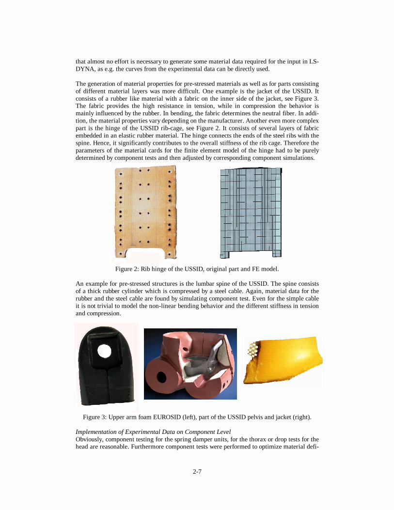
The generation of material properties for pre-stressed materials as well as for parts consistingof different material layers was more difficult. One example is the jacket of the USSID. Itconsists of a rubber like material with a fabric on the inner side of the jacket, see Figure 3.The fabric provides the high resistance in tension, while in compression the behavior ismainly influenced by the rubber. In bending, the fabric determines the neutral fiber. In addi-tion, the material properties vary depending on the manufacturer. Another even more complexpart is the hinge of the USSID rib-cage, see Figure 2. It consists of several layers of fabricembedded in an elastic rubber material. The hinge connects the ends of the steel ribs with thespine. Hence, it significantly contributes to the overall stiffness of the rib cage. Therefore theparameters of the material cards for the finite element model of the hinge had to be purelydetermined by component tests and then adjusted by corresponding component simulations.
Figure 2: Rib hinge of the USSID, original part and FE model.
An example for pre-stressed structures is the lumbar spine of the USSID. The spine consistsof a thick rubber cylinder which is compressed by a steel cable. Again, material data for therubber and the steel cable are found by simulating component test. Even for the simple cableit is not trivial to model the non-linear bending behavior and the different stiffness in tensionand compression.
Figure 3: Upper arm foam EUROSID (left), part of the USSID pelvis and jacket (right).
Implementation of Experimental Data on Component LevelObviously, component testing for the spring damper units, for the thorax or drop tests for thehead are reasonable. Furthermore component tests were performed to optimize material defi-

2-8
nitions, if the material tests were not possible, as described above. In addition, some compo-nent tests were defined to consider blocking and sticking effects. For instance non-lateralimpacts on the thorax were performed. The crucial question for all experiments was to definea load scenario close to the loading expected in an side impact crash. Trivially, the strain rateeffects in foams are visible, if a structure is loaded with the corresponding strain rates. Unfor-tunately, the majority of experimental data available for the calibration of the hardwaredummy is obtained at considerably low loading velocities. Furthermore, the geometry ofcomponents is extremely important for their behavior, however, it is often neglected. As ex-amples the complex geometry of the a pelvis and the upper arm foam of the EUROSID aredepicted in Figure 3.
Even for foam materials small adaptations had to be made, since the behavior of the open cellfoams depends on the outflow of the air. Hence, the size of the specimen, the open surfaceand the venyl coverings influence the properties of the part, unless this effect is consideredwithin a further model.
The difficulties to define appropriate component tests can be demonstrated on the alreadymentioned simple example of the lumbar spine. Depending on the impact we observe a super-position of shear, bending, torsion and tension. Often the loads result in small deflectionsonly. A pure pendulum test (see Figure 4) is considered in the following, where the spine isclamped between a long pendulum and a defined mass at the bottom. Initially, all parts havethe same rotational velocity around the joint of the pendulum. In the experiment the pendulumis decelerated by a block out of honeycombmaterial. For this simple test the initial and theboundary conditions are clearly defined. In the test we have to work with high angular veloci-ties to have the same initial conditions as in a crash. This results in rather high deflectionswhich usually do not appear in the dummy. However, the test gives important information onthe bending behavior, despite the effect of the combination with other observed loading isneglected. Test procedures combining the different types of loading are very difficult to per-form. In addition, it must be mentioned that the test racks have complex designs which oftenresults in uncertainties in the boundary conditions, particularly for high speed tests.
Figure 4: FE model of the lower spine in the pendulum test.
Since the deflections of the spine of the dummies are usually small, already the beginning ofthe bending of the spine must be carefully considered. In order to achieve this, the materialproperties must be optimized for a good correlation in this phase. The correlation in the laterbending phase, however, is secondary for the dummy development. Such a selective accen-tuation of test data seems to be one of the key issues during the development of the finiteelement models.

2-9
Implementation of Experimental Data from the Sled TestsThe considerations about appropriate loading as presented above is also a major argument touse test data of sled tests to further enhance the finite element models. In the majority of thesled tests rather rigid barriers, some even with mounted airbags, are used. Since the dummiesshow considerably good correlation in integrated simulations, it seems sufficient to usemainly rigid barriers during the development also in the simulation models. The simulation ofthe sled tests, however, showed new phenomena manly affected by the interaction of differentparts in contact. Hence, the proper modeling of the complex contact situations becomes a highpriority. For some soft foams the correct modeling of the contact, allowing almost no pene-tration, caused difficulties for the stability. The latter is a result of the high deformation, asthese soft foams get frequently extremely squeezed between different parts. Particularly theabdominal inserts and the arm foam of the USSID needed additional consideration concerningcontact and contact stiffness. Interestingly the real hardware dummies show often damage inexactly these foam parts. The stability of the created FE models is tested with the simulationat very high loads. Even for these extreme loads a good correlation with test data is oftenachieved. Different stages of deformation of the arm foam are depicted in Figure 5.
Figure 5: Deformation of the soft arm foam of the USSSID in a sled test.
The significant advantage of getting more appropriate loading from sled tests yields to thequestion if the material tests and the component test would be dispensable. However, thesimulations with the fully assembled models have the clear disadvantage that it is very diffi-cult to locate the corresponding entities to modify the models correctly, as the results aredetermined by many factors affecting each other. Thus it is very difficult to assign a signal toa single specific event in the model. Roughly speaking: There are far too many unknowns inthe equations for a good inverse analysis. Basically, the work with the experimental data fromthe sled test is comparable with a common nonlinear optimization problem. From optimiza-tion theory it is known how important a good starting point is. The goal of the material andcomponent test is to reduce this figure of unknowns and to provide a good staring point bysticking to the original idea of FE modeling with continuum theory and corresponding mate-rial models and material data. For the dummy development this implies that the finite ele-ment models must already have a certain quality, until the model can be enhanced with sledtest data. Then an optimum between efficient modeling and necessary detailing can beachieved.
Additional AspectsDuring the development experiments of the EUROSID were performed with the jacket andwithout the jacket. The jacket is made of Neoprene material with approximately 5 mm thick-ness. Even for the plane barrier the rib intrusion varies significantly for both cases as shown

2-10
in Figure 6. Due to the lack of the jacket a higher rib intrusion should be expected, however,the opposite is measured. The difference is mainly a result of the different motion of the arm.It is generally observed that the model is highly sensitive against the motion of the arm on theimpacted side. For this experiment the major dependence is on the difference in friction a)between arm and barrier as well as b) between arm and ribs. Hence, in a simulation greatcaution has to be taken to use sufficiently accurate models also for the parts interacting withthe dummies thus the car interior and the airbag.
Figure 6: EUROSID, upper (left) and lower (right) rib intrusion vs. time, plane barrier;rib cage with and without jacket
Successive re- and de-refinementAbove we have seen, that for the definition of test procedures on material and componentbasis specific knowledge on the loading during the side impact crash is vital. In many cases,however, it is not possible to get this information from the hardware dummies, since it can notbe measured. Hence, finite element models appear to be a good instrument to obtain the de-sired information. This kind of inverse problem lead to the methodology applied in the projectwhich we named ‘successive re- and de-refinement’. First data from simulations with coursemodels were used to predict the loads. Based on this information the material and componenttests were defined. The results of the tests were again used to correct the dummy models. Thisprocedure was repeated a couple of times. Within these development loops the models weremostly refined; less often a de-refinement was possible. Different stages of discretization forthe pelvis of the USSID are depicted in Figure 7 representing different states in the loop. Foreach stage the geometry is modeled with more details. New element technologies are used.The element size of the deformable parts were first refined significantly and later de-refinedslightly. Furthermore, the geometry of the outer hull of the pelvis is modified from version2.5 to 3.0. As material model initially Viscous_Foam (Type 62) was used, then material typeLow_Density_Foam (Type 57), and finally, Fu_Chang_Foam (Type 83) was taken.
The original models for the EUROSID and the USSID were first enhanced based on barriertests (Erbelding C., Kurz A., Schelkle A., 1996). These models were then used by the mem-bers of the FAT in full car crashes. Furthermore, the FAT used the models to analyze theloading in some detail. The result was the specification of tests procedures on material, com-ponent and fully assembled level. Often further ideas for appropriate tests were proposedduring the enhancements of the models. Thus performing tests was an ongoing process duringthe development. For instance, more than 4 series of materials tests were performed for theEUROSID parallel to the model development.

2-11
Figure 7: Development stages of the pelvis of the USSID(top: Version 1.00; left: Version 2.5; right: Version 3.0).
MODEL DESCRIPTION
Commercially available are currently version 2.0 for the EUROSID and version 2.5 of theUSSID. Version 2.5 for the EUROSID will be available soon. Both consist of approximately30,000 nodes, 20,000 brick elements (mainly tetrahedrons; element type 10 in LS-DYNA)and 20,000 shell elements (mainly Belytschko-Tsay elements) and a couple of discrete andbeam elements and more than 100 part/material definitions. For modeling the foam materialsusually material type 83 (Fu_Chang_Foam) is employed. In some cases the extensions ofmaterial law 83 (Hirth A., Du Bois P., Weimar K.,1998) are applied. Only a few foam partsare modeled with material model 62 (Viscous_Foam). For modeling the venyl skins differentmodels are used: Depending on the importance, material type 61 (Maxwell/Kelvin Viscoelas-tic with Maximum Strain) or material type 1 (Elastic) are chosen. Material law 76 (GeneralViscoelastic) is used to describe the jacket of theUSSID. Rubber parts are modeled withmaterial type 6 (Viscoelastic) or type 61 (Maxwell/Kelvin Viscoelastic with MaximumStrain). The majority of the iron or aluminum parts are modeled with material type 20(Rigid). In some soft foam parts material Type 9 (Null), usually combined with shells areused to avoid element collapse. One major single surface contact (Type 13) with the softconstraint option is used to model the contacts in the dummy. The contact takes the realthickness into account. All contact parameters are default settings. In addition, contact typeAutomatic General (Type26) is applied in specific areas. The recent models use the stiffnessbased joint definition in combination with the generalized stiffness option. Global damping isnot applied. The models run with LS-DYNA version 950a upwards.

2-12
BARRIER TEST CORRELATION
In the following the correlation of the simulation with barrier sled tests is presented. Thefollowing graphs depict the experimental results in thin dashed lines, the simulated signals areprinted with thick lines. Since the performance of the FAT USSID model Version 2.5 wasalready presented in (Franz U., Graf O., 2000), (Graf O., Walz M., Franz U., 1999) and(Franz U., Graf O., Walz M., 1999) only a short excerption is given in the following. Moreresults are presented for the EUROSID. Since Version 2.5 for the EUROSID is upcomingsoon results are presented for version 2.0 and the beta-release of version 2.5.
Barrier with Arm Impactor, FAT USSID Version 2.5
Figure 8: Model during sled test, acceleration [g] in pelvis vs. time [ms].
Figure 9: Acceleration [g] upper and lower rib vs. time [ms].

2-13
Barrier with Pelvis Impactor, FAT USSID Version 2.5
Figure 10: Accel. [g]upper (right top) and lower rib vs. time [ms], barrier velocity 8 m/s.
Figure 11: Accel. [g] pelvis (left) and lower spine vs.time [ms], barrier velocity 6 m/s.

2-14
Plane Barrier, FAT EUROSID Version 2.0
Figure 12: EUROSID during impact.
Figure 13: Acceleration [g] for pelvis and upper spine vs. time [ms].

2-15
Plane Barrier, FAT EUROSID Version 2.0
Figure 14: Acceleration [g] and intrusion [mm] upper rib vs. time [ms].
Figure 15: Acceleration [g] and intrusion [mm] middle rib vs. time [ms].
Figure 16: Acceleration [g] and intrusion [mm] lower rib vs. time [ms].

2-16
Plane Barrier, FAT EUROSID Version 2.5 (beta)
Figure 17: Acceleration [g] and intrusion [mm] upper rib vs. time [ms].
Figure 18: Acceleration [g] and intrusion [mm] middle rib vs. time [ms].
Figure 19: Acceleration [g] and intrusion [mm] lower rib vs. time [ms].

2-17
Barrier with Pelvis Impactor, FAT EUROSID Version 2.5 (beta)
Figure 20: EUROSID during impact.
Figure 21: FAT EUROSID model in the simulation.

2-18
Barrier with Pelvis Impactor, FAT EUROSID Version 2.5 (beta)
Figure 22: Acceleration [g] upper and lower spine vs. time [ms].
Figure 23: Acceleration [g] and force [kN] pelvis vs. time [ms].
Figure 24: Acceleration [g] upper and middle rib vs. time [ms].

2-19
CONCLUSIONS
The methodology applied in the development of the FAT dummy models was outlined. Theindispensable need of both, component and sled tests is explained using simple examples.
The LS-DYNA FAT USSID and EUROSID models are validated using a wide range of ex-perimental data. The models rely on many new features of LS-DYNA to describe the occur-ring effects. The features available in LS-DYNA allow the direct use of a wide range of ex-perimental data. Regarding other finite element dummy models, the FAT models are capableto capture many details with very high complexity with relative high efficiency. The majorgoal of the cooperation of CAD-FEM with the FAT to generate accurate and stable finiteelement models has succeeded up to now.
The models are commercially available in version 2.0 for the EUROSID and 2.5 for the US-SID. The results of the simulation presented in the paper show the good performance of themodels compared to experiments.
ACKNOWLEDGMENTS
The authors would like to thank the LS-DYNA users of the FAT project for the encouragingsupport. In particular we express our thanks to Mr. Andreas Hirth from DaimlerChrysler AGfor his substantial contribution during the development of the USSID. In addition, we thankMr. Matthias Walz from Daimler Chrysler AG for his strong engagement.
REFERENCES
ERBELDING C., KURZ A., SCHELKLE A., (1996), “Development of Finite Element Side-Impact Dummies: A contribution to efficient occupant simulation”. Berechnung und Simula-tion im Fahrzeugbau. Tagung Würzburg. VDI-Gesellschaft Fahrzeug- und Verkehrstechnik.VDI-Berichte: 1283. ISBN 318 091283 9,Page: 263 to 282
FRANZ U., WALZ M., RUST W., (1998), “CAD-FEM development of finite element sideimpact dummy models in cooperation with the German automotive industry”, 5th InternationalLS-DYNA Conference, Detroit, USA.
FRANZ U., GRAF O., WALZ M., (1999), “ENHANCEMENTS TO THE FAT FEDUMMIES USING SPECIFIC FEATURES OF LS-DYNA“, 2nd European LS-DYNA Con-ference, Gothenburg, Sweden.
FRANZ U., GRAF O., (2000), “Development of the FAT Dummies“, CAE 2000 Conference,Fujitsu, Nagoya, Japan.
FAT, (1997), “FAT im Überblick“. Forschungsvereinigung Automobiltechnik e. V. (FAT).Westendstrasse 61, 60325 Frankfurt, Germany.
GIBSON L., ASHBY M., (1998), “Cellular Solids Structure & Properties”, Pergamon PressOxford, New York.
GRAF O., WALZ M., FRANZ U.,(1999), “Erfolgreiche Anwendung neuer LS-DYNA Fea-tures bei der Entwicklung des FAT-USSID“, 17th CAD-FEM Users’Meeting, Sonthofen,Germany

2-20
HIRTH A., DU BOIS P., WEIMAR K., (1998), “Erweiterungen des LS-DYNA M aterial-gesetzes 83 (Fu Chang) für die industrielle Simulation von energieabsorbierenden reversiblenSchäumen“, 16th CAD-FEM Users’ Meeting, Bad Neuenahr-Ahrweiler, Germany.
HIRTH A., DU BOIS P., (1999), “From complex 3D-foam parts to ready input data in lessthan one hour”, 2ndEuropean LS-DYNA Conference, Gothenburg, Sweden.
JANSSEN A., VERSCHUT R., SALADIN A.,(1995), “ New Instrumentation for EUROSID1”, TNO, Information Document, Netherlands.