accessory kit installation manual - upgnet · accessory kit installation manual ... twin 60 90 120...
TRANSCRIPT
Johnson Controls Unitary Products 035-22285-002-B-0914
ACCESSORY KIT INSTALLATION MANUAL IGNITION CONTROL P/N S1-33103010000
FOR MODELS: ALL SINGLE-STAGE 115VAC MODELS WITH HOT SURFACE IGNITION (HSI)
GENERAL INFORMATIONThis part is a direct replacement for part numbers S1-03109167000, S1-03101933000, S1-03101267000,S1-03101267001, S1-03100662000, S1-03101250000,S1-03101266000, S1-03101284000, S1-03101973000and S1-03101972000, 265901, 265902, & 539617.
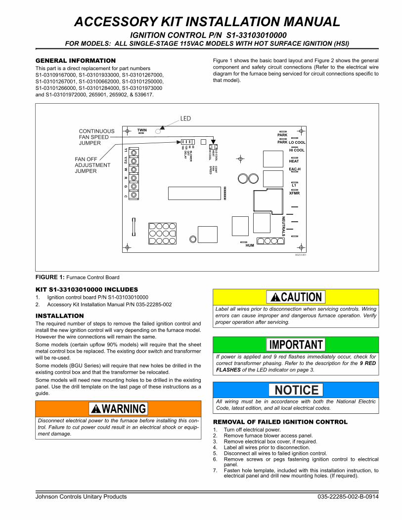
Figure 1 shows the basic board layout and Figure 2 shows the generalcomponent and safety circuit connections (Refer to the electrical wirediagram for the furnace being serviced for circuit connections specific tothat model).
KIT S1-33103010000 INCLUDES1. Ignition control board P/N S1-031030100002. Accessory Kit Installation Manual P/N 035-22285-002
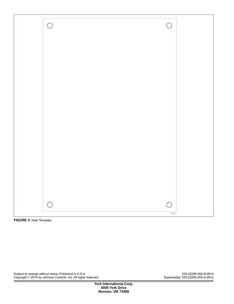
INSTALLATIONThe required number of steps to remove the failed ignition control andinstall the new ignition control will vary depending on the furnace model.However the wire connections will remain the same.Some models (certain upflow 90% models) will require that the sheetmetal control box be replaced. The existing door switch and transformerwill be re-used.Some models (BGU Series) will require that new holes be drilled in theexisting control box and that the transformer be relocated.Some models will need new mounting holes to be drilled in the existingpanel. Use the drill template on the last page of these instructions as aguide.
REMOVAL OF FAILED IGNITION CONTROL1. Turn off electrical power.2. Remove furnace blower access panel.3. Remove electrical box cover, if required.4. Label all wires prior to disconnection.5. Disconnect all wires to failed ignition control.6. Remove screws or pegs fastening ignition control to electrical
panel.7. Fasten hole template, included with this installation instruction, to
electrical panel and drill new mounting holes. (If required).
FIGURE 1: Furnace Control Board
PARK
PARK
HI COOL
HEAT
EAC-H
L1
XFMR
NE
UT
RA
LS
HUM
TWIN
60
90
12
0
18
0
BL
OW
ER
OF
F
DE
LA
YY/Y
2W
RG
CY
1
LO COOL
CO
NT
FA
N
SP
EE
D
LO
CO
OL
HE
AT
HI C
OO
L
FAN OFF
ADJUSTMENT
JUMPER
CONTINUOUS
FAN SPEED
JUMPER
A0233-001
LED
Disconnect electrical power to the furnace before installing this con-trol. Failure to cut power could result in an electrical shock or equip-ment damage.
Label all wires prior to disconnection when servicing controls. Wiringerrors can cause improper and dangerous furnace operation. Verifyproper operation after servicing.
If power is applied and 9 red flashes immediately occur, check forcorrect transformer phasing. Refer to the description for the 9 REDFLASHES of the LED indicator on page 3.
All wiring must be in accordance with both the National ElectricCode, latest edition, and all local electrical codes.
NOTICE
035-22285-002-B-0914
2 Johnson Controls Unitary Products
INSTALLATION OF IGNITION CONTROL1. Orient the control as close as possible to the orientation of the
board being replaced.2. Align the plastic mounting feet with the mounting holes in the elec-
tric panel and press on each corner of the control board to seat themounting feet.
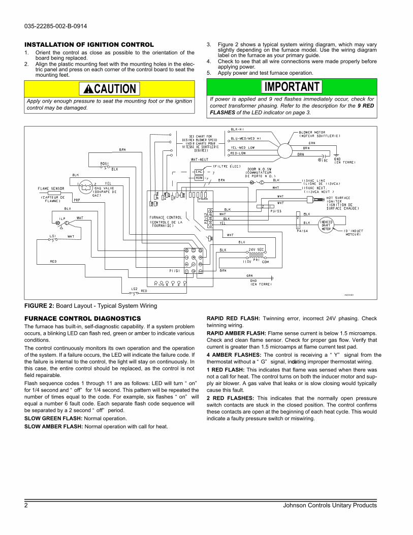
3. Figure 2 shows a typical system wiring diagram, which may varyslightly depending on the furnace model. Use the wiring diagramlabel on the furnace as your primary guide.
4. Check to see that all wire connections were made properly beforeapplying power.
5. Apply power and test furnace operation.
FURNACE CONTROL DIAGNOSTICSThe furnace has built-in, self-diagnostic capability. If a system problemoccurs, a blinking LED can flash red, green or amber to indicate variousconditions.The control continuously monitors its own operation and the operationof the system. If a failure occurs, the LED will indicate the failure code. Ifthe failure is internal to the control, the light will stay on continuously. Inthis case, the entire control should be replaced, as the control is notfield repairable.Flash sequence codes 1 through 11 are as follows: LED will turn “on”for 1/4 second and “off” for 1/4 second. This pattern will be repeated thenumber of times equal to the code. For example, six flashes “on” willequal a number 6 fault code. Each separate flash code sequence willbe separated by a 2 second “off” period.SLOW GREEN FLASH: Normal operation.SLOW AMBER FLASH: Normal operation with call for heat.
RAPID RED FLASH: Twinning error, incorrect 24V phasing. Checktwinning wiring.RAPID AMBER FLASH: Flame sense current is below 1.5 microamps.Check and clean flame sensor. Check for proper gas flow. Verify thatcurrent is greater than 1.5 microamps at flame current test pad.4 AMBER FLASHES: The control is receiving a “Y” signal from thethermostat without a “G” signal, indicating improper thermostat wiring.1 RED FLASH: This indicates that flame was sensed when there wasnot a call for heat. The control turns on both the inducer motor and sup-ply air blower. A gas valve that leaks or is slow closing would typicallycause this fault.2 RED FLASHES: This indicates that the normally open pressureswitch contacts are stuck in the closed position. The control confirmsthese contacts are open at the beginning of each heat cycle. This wouldindicate a faulty pressure switch or miswiring.
Apply only enough pressure to seat the mounting foot or the ignitioncontrol may be damaged.
If power is applied and 9 red flashes immediately occur, check forcorrect transformer phasing. Refer to the description for the 9 REDFLASHES of the LED indicator on page 3.
FIGURE 2: Board Layout - Typical System Wiring
A0234-001

035-22285-002-B-0914
Johnson Controls Unitary Products 3
3 RED FLASHES: This indicates the normally open pressure switchcontact did not close after the inducer was energized. This could becaused by a number of problems: faulty inducer, blocked vent pipe, bro-ken pressure switch hose or faulty pressure switch.DO NOT assume a pressure switch is faulty. Connect a manometerusing a tee fitting to verify vent pressure.4 RED FLASHES: This indicates that a primary or auxiliary limit switchhas opened its normally closed contacts. The control operates the sup-ply air blower and inducer. This condition may be caused by: dirty filter,improperly sized duct system, incorrect blower speed setting, incorrectfiring rate or faulty blower motor. Also, this fault code could be causedby a blown fuse located on the control board.5 RED FLASHES: This fault is indicated if the normally closed contactsin the rollout switch opens. The rollout control is manually reset. If the contacts have opened, check for proper combustion air, properinducer operation, and primary heat exchanger failure or burner prob-lem. Be sure to reset the switch and cycle power (24 VAC) to the controlafter correcting the failure condition. Check for a blown fuse located onthe control board which can cause this fault code.6 RED FLASHES: This indicates that after the unit was operating, thepressure switch opened 4 times during the call for heat. If the mainblower is in a “Delay on” mode, it completes the delay period, and anysubsequent delay off period. The furnace locks out for one hour andthen restart.7 RED FLASHES: This fault code indicates that the flame could not beestablished. This no-light condition occurred 3 times (2 retries) duringthe call for heat before locking out. Low gas pressure, faulty gas valve,dirty or faulty flame sensor, faulty hot surface ignitor or burner problemmay cause this. The furnace locks out for one hour and then restart.8 RED FLASHES: This fault is indicated if the flame is lost 5 times (4recycles) during the heating cycle. This could be caused by low gaspressure, dirty or faulty flame sensor or faulty gas valve. The furnacelocks out for one hour and then restart.9 RED FLASHES: Indicates reversed line voltage polarity or groundingproblem, or incorrect 24V phasing. The 24V phasing can be checked bymeasuring the 120V line to the 24V “R” terminal. Line voltage minussecondary voltage should be indicated. If line voltage plus secondaryvoltage is indicated, low voltage is out of phase with line voltage. The24V secondary voltage at the transformer connections must bereversed. Both heating and cooling operations are affected. Check polarity at furnace and branch. Check furnace grounding. Checkthat flame probe is not shorted to chassis.10 RED FLASHES: Indicates flame sensed with no call for heat. Check gas valve, gas valve wiring, and proper grounding.11 RED FLASHES: This indicates that a primary or auxiliary limit switchhas opened its normally-closed contacts and has remained open formore than five minutes. This condition is usually caused by a failed
blower motor or blower wheel. Cycle power (24 VAC) to the control toreset the hard lockout condition after correcting the failure condition.12 RED FLASHES: This code indicates an open igniter circuit, whichcould be a disconnected or loose wire or a cracked or broken igniter.STEADY ON RED: Control failure. Replace control board.60-MINUTE AUTOMATIC RESET FROM LOCKOUT: This controlincludes a “watchdog” type circuit that resets from a lockout conditionafter 60 minutes. The operational faults 6, 7, and 8 also reset. This pro-vides protection to an unoccupied structure if a temporary conditionexists causing a furnace malfunction. An example would be a lowincoming gas supply pressure preventing unit operation. When the gaspressure is restored, at some point the “watchdog” would restart theunit and provide heat for the structure. If a flame is detected, the controlflashes the LED for 1/8 of a second and then enters a flame stabiliza-tion period.
DIAGNOSTIC FAULT CODE STORAGE AND RETRIEVALThe control in this furnace is equipped with memory that will store up tofive error codes to allow a service technician to diagnose problemsmore easily. This memory will be retained even if power to the furnaceis lost. This feature should only be used by a qualified service technician. The control stores up to five separate error codes. If more than fiveerror codes have occurred since the last reset, only the five most recenterror codes are retained. The furnace control board has a button,labeled “LAST ERROR” that is used to retrieve error codes. This func-tion only works if there are no active thermostat signals. A call for heat-ing, cooling or continuous fan must be terminated before attempting toretrieve error codes. To retrieve the error codes, push the LAST ERROR button. The LED onthe control board then flashes the error codes that are in memory, start-ing with the most recent. There is a two-second pause between each ofthe error flash codes. After the error codes have all been displayed, theLED resumes the normal slow green flash after a five second pause. Torepeat the series of error codes, push the button again. If there are noerror codes in memory, the LED flashes two green flashes. To clear thememory, push the LAST ERROR button and hold it for more than fiveseconds. The LED flash three green flashes when the memory hasbeen cleared, and then the LED resumes the normal slow green flashafter a five-second pause.
IGNITION CONTROLNormal flame sense current is approximately
3.7 microamps DC (µa)Low flame signal warning starts at 1.5 microamps.
Low flame signal control lockout point is0.1 microamp DC (µa)
Subject to change without notice. Published in U.S.A. 035-22285-002-B-0914Copyright © 2014 by Johnson Controls, Inc. All rights reserved. Supersedes: 035-22285-002-A-0912
York International Corp.5005 York Drive
Norman, OK 73069
FIGURE 3: Hole Template
A0235-001