accessories subplates and connection plates for four …pub/@eaton/@hyd/... · subplates and...
TRANSCRIPT
P
B
T
A
A B
P
T
P
A B
TA TB
PT
A B
X
Y
L
PT
A BX
Y
L
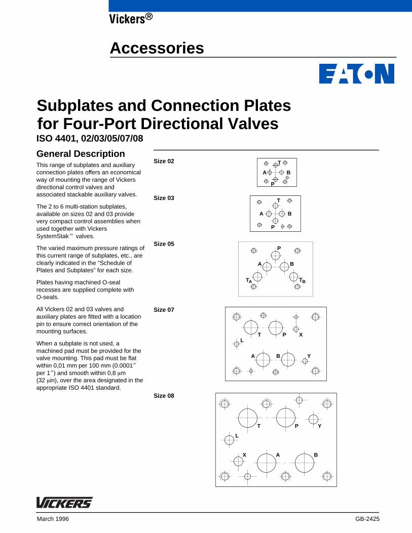
Size 02
Size 03
Size 05
Size 07
Size 08
March 1996 GB-2425
ISO 4401, 02/03/05/07/08
General DescriptionThis range of subplates and auxiliaryconnection plates offers an economicalway of mounting the range of Vickersdirectional control valves andassociated stackable auxiliary valves.
The 2 to 6 multi-station subplates,available on sizes 02 and 03 providevery compact control assemblies whenused together with VickersSystemStak� valves.
The varied maximum pressure ratings ofthis current range of subplates, etc., areclearly indicated in the “Schedule ofPlates and Subplates” for each size.
Plates having machined O-sealrecesses are supplied complete withO-seals.
All Vickers 02 and 03 valves andauxiliary plates are fitted with a locationpin to ensure correct orientation of themounting surfaces.
When a subplate is not used, amachined pad must be provided for thevalve mounting. This pad must be flatwithin 0,01 mm per 100 mm (0.0001�per 1�) and smooth within 0,8 �m (32 �in), over the area designated in theappropriate ISO 4401 standard.
Accessories
Vickers®
Subplates and Connection Platesfor Four-Port Directional Valves

2
Table of Contents – Size 02
Description and Mass kg (lb) Functional Symbol Model Code Max. Pressure
Mounting Surface to ISO 4401
Blanking plateCast iron 0,24 (0.53)
P AT B
DGMA-2-B-1* 250 bar (3600 psi)
Crossover plate P-A; B-TCast iron 0,21 (0.46)
P T B A
DGMA-2-C1-1* 250 bar (3600 psi)
Crossover plate P-B; A-TCast iron 0,21 (0.46)
P T B A
DGMA-2-C2-1* 250 bar (3600 psi)
Tapping plate, ports A and BCast iron 0,28 (0.62)
P T B A
DGMA-2-T1-1*-R�DGMA-2-T1-1*-S�
250 bar (3600 psi)
Tapping plate, ports P and TCast iron 0,28 (0.62)
P T B A
DGMA-2-T2-1*-R�DGMA-2-T2-1*-S�
250 bar (3600 psi)
Orifice plateCast iron 0,12 (0.27)
P T B A
DGOM-2-1*-R� 250 bar (3600 psi)
Adaptor plate, DG4M4 to size 02Cast iron 0,6 (1.2)
P T B A
Size 2
DG4M4
P T B ADGAM-2-4-10-R�DGAM-2-4-10-S�
250 bar (3600 psi)
Adaptor plate, size 03 to 02Cast iron 0,43 (0.95)
P T B A
Size 2
Size 3
P T B ADGAM-2-3-1*-R�DGAM-2-3-1*-S�
250 bar (3600 psi)
Single-station subplate;side ports P, T, A, BAluminium 0,13 (0.29) T B
AP
DGMS-2-1E-1*-R�DGMS-2-1E-1*-S�
250 bar (3600 psi)
Multi-station subplate/manifold;side ports P, T, A1, B1, A2, B2, etc.2-stationAluminium 1,36 (3.0)3-stationAluminium 1,85 (4.1)
PT
B1 A1
P1 T1 B1 A1
B2 A2
P2 T2 B2 A2
Valve station 1 Valve stations 2-3
DGMS-2-2E-1*-R�DGMS-2-2E-1*-S�DGMS-2-3E-1*-R�DGMS-2-3E-1*-S�
250 bar (3600 psi)
Multi-station subplate/manifold;side ports P, T, A1, B1, A2, B2, etc.4-station Aluminium 2,36 (5.2)5-station Aluminium 2,87 (6.3)6-station Aluminium 3,37 (7.4)
PT
B1 A1
P1 T1 B1 A1
B6 A6
P6 T6 B6 A6
Valve station 1 Valve stations 2-6 DGMS-2-4E-1*-R�DGMS-2-4E-1*-S�DGMS-2-5E-1*-R�DGMS-2-5E-1*-S�DGMS-2-6E-1*-R�DGMS-2-6E-1*-S�
250 bar (3600 psi)
* Design number subject to change. No change of installation dimensions for design numbers 10 to 19 or 21 to 29 inclusive.
� “S” suffix = SAE/UNC ports and/or UNC fixing bolt tappings and/or orifice plugs as appropriate.“R” = ISO 228 (BSPF) ports and/or metric fixing bolt tappings and/or orifice plugs as appropriate.

3
Table of Contents – Size 03
Description and Mass kg (lb) Functional Symbol Model Code Max. Pressure
Mounting Surface to ISO 4401
Blanking plateCast iron 0,5 (1.1)
P AT B
DGMA-3-B-1*
350 bar (5000 psi)
Crossover plate P-A; B-TCast iron 0,5 (1.1)
P AT B
DGMA-3-C1-1* 350 bar (5000 psi)
Crossover plate P-B; A-TCast iron 0,5 (1.1)
P AT B
DGMA-3-C2-1* 350 bar (5000 psi)
Tapping plate, ports A and BCast iron 0,5 (1.1)
P AT B
ABDGMA-3-T1-1*-B�DGMA-3-T1-2*-S�
350 bar (5000 psi)
Tapping plate, ports P and TCast iron 0,5 (1.1)
P AT B
P TDGMA-3-T2-1*-B�DGMA-3-T2-2*-S�
350 bar (5000 psi)
Single-station subplate;rear ports P, T, A, BCast iron 1,3 (2.9) P AT B
DGVM-3-1*-R�DGVM-3-1*-S�
250 bar (3600 psi)
Single-station subplate;rear ports P, T, A, B; side port LCast iron 1,3 (2.9) P AT B
LKDGVM-3-1*-R�KDGVM-3-676803-1*(SAE/UNF ports)
250 bar (3600 psi)
Single-station subplate;side ports P, T, A, BCast iron 1,3 (2.9)
PT
AB
DGMS-3-1E-1*-R�DGMS-3-1E(Y)-1*-S�
250 bar (3600 psi)
Adaptor, size 05 to 03Cast iron 0,6 (1.3)
P ATA B
P AT BSize 03
Size 05TB
DGAM-3-01-1*-R�DGAM-3-01-1* (UNCvalve mounting bolts)
210 bar (3000 psi)
Multi-station subplate/manifold;side ports P, T, A1, B1, A2, B2, etc.2-stationCast iron 4,0 (8.8)3-stationCast iron 5,5 (12.1)
P1 A1T1 P2 A2T2 B2PT
PuTu
B1
A1 A2B2B1
Valve station 1 Valve station 2
DGMS-3-2E-1*-R�DGMS-3-2E(X)-1*-S�DGMS-3-3E-1*-R�DGMS-3-3E(X)-1*-S�
250 bar (3600 psi)
u Through-connection P and T ports on types DGMS-3-2EX-1*-* and DGMS-3-3EX-1-*.
Multi-station subplate/manifold;side ports P, T, A1, B1, A2, B2, etc.4-stationCast iron 7,0 (15.4)5-stationCast iron 8,5 (18.7)6-stationCast iron 10,0 (22.0)
PT
PT
P1 A1T1 P6 A6T6 B6B1
A1 A6B6B1
Valve station 1 Valve station 6DGMS-3-4E-1*-R�DGMS-3-4E-1*-S�DGMS-3-5E-1*-R�DGMS-3-5E-1*-S�DGMS-3-6E-1*-R�DGMS-3-6E-1*-S�
250 bar (3600 psi)
* Design number subject to change. No change of installation dimensions for design numbers 10 to 19 or 21 to 29 inclusive.
� “S” suffix = SAE/UNC ports and/or UNC fixing bolt tappings and/or orifice plugs as appropriate.“R” or “B” = ISO 228 (BSPF) ports and/or metric fixing bolt tappings and/or orifice plugsas appropriate.

4
Table of Contents – Size 05
Description and Mass kg (lb) Functional Symbol Model Code Max. Pressure
Mounting Surface to ISO 4401
Blanking plateCast iron 2,9 (6.4)
P TATB B A
DGMA-5-B-1*
315 bar (4500 psi)
Crossover plate P-A; B-TCast iron 2,9 (6.4)
P TATB B A
DGMA-5-C1-1* 315 bar (4500 psi)
Crossover plate P-B; A-TCast iron 2,9 (6.4)
P TATB B A
DGMA-5-C2-1* 315 bar (4500 psi)
Tapping plate, ports A and BCast iron 0,5 (1.1)
P TATB B A
DGMA-5-T1-1*-B� 315 bar (4500 psi)
Tapping plate, ports P and TCast iron 0,5 (1.1)
P TATB B A
DGMA-5-T2-1*-B�
315 bar (4500 psi)
Tapping plate, ports P, A and BCast iron 0,5 (1.1)
P TATB B A
DGMA-5-T3-1*-B�
315 bar (4500 psi)
Adaptor plate for pilot portsX and YCast iron 1,4 (3.1)
YX
P TATB B A
DGAM-5-1*-R�DGAM-5-1*-S�
210 bar (3000 psi)
Single-station subplate;side ports P, T, A, BCast iron 2,0 (4.4)
PT
AB
DGSME-01-2*-T8�
210 bar (3000 psi)
Single-station subplate;rear ports P, T, A, BCast iron 2,0 (4.4)
P T B A
DGSM-01-2*-T8�EDGSM-01-1*-R�EDGSM-01X-1*-R�EDGSM-01Y-1*-R�
210 bar (3000 psi)280 bar (4000 psi)
Single-station subplate;rear ports P, T, A, B; and port L(side or rear)Cast iron 1,3 (2.9) P T B A L
L
P T B A
KDGSM-5-676805-2*(SAE/UNF ports)
KDGSM-5-615225-1*(1/2� BSPF ports)KDGSM-5-615226-1*(3/4� BSPF ports)
EKDGSM-01Y-1*-R�
210 bar (3000 psi)
315 bar (4500 psi)
280 bar (4000 psi)
Single-station subplate;rear ports P, T, A, B plus X and YCast iron 2,0 (4.4)
YX P T B A
EDGSM-03-1*-R�EDGSM-03X-1*-R�EDGSM-03X-1*-S�
210 bar (3000 psi)
* Design number subject to change. No change of installation dimensions for design numbers 10 to 19 or 21 to 29 inclusive.
� “S” or “T8” suffix = SAE/UNC ports and/or UNC fixing bolt tappings and/or orifice plugs as appropriate.“R” or “B” = ISO 228 (BSPF) ports and/or metric fixing bolt tappings and/or orifice plugsas appropriate.

5
Table of Contents – Sizes 07 and 08
Description and Mass kg (lb) Functional Symbol Model Code Max. Pressure
Mounting Surface to ISO 4401
Single-station subplateCast iron 3,8 (8.4)Cast iron 3,8 (8.4)Cast iron 6,1 (13.4)Cast iron 5,0 (11)Cast iron 5,0 (11)Cast iron 13 (28.6)
YX P T B AL
DGSM-04EDGVM-7XEDGVM-7Y/7ZDGSM-8EDGVM-8XEDGVM-8Y/8Z
210 bar (3000 psi)350 bar (5000 psi)350 bar (5000 psi)210 bar (3000 psi)350 bar (5000 psi)350 bar (5000 psi)
Operating Data
Maximum flow rates No functional limitations: dependent on valves used
Hydraulic fluids Compatible with all fluids recommended for Vickers sizes 02, 03, 05, 07,and 08 valves
Temperature limits As for valves, subject to limits: –20�C to 70�C (–4�F to 158�F)
Mounting attitude No restrictions, other than for valves fitted
Bolt Kits for Mounting Valves
Valve Size Bolt ThreadsMetric Inch
Torque (threads lubricated)
02 M5-6H #10-24 UNC-2B 5-7 Nm (44-62 lbf in)
03 M5-6H #10-24 UNC-2B 7-9 Nm (62-79 lbf in)
05 M6-16H 1/4�-20 UNC-2B 9-14 Nm (79-124 lbf in)
07 M10M6
3/8�-16 UNC-2B1/4�-20 UNC-2B
49-59 Nm (434-522 lbf in)9-14 Nm (79-124 lbf in)
08 M12-6H 1/2�-13 UNC-2B 103-127 Nm (912-1124 lbf in)
Note:If not using Vickers recommended bolt kits, bolts used should be to ISO 898 class 12.9 or better.Use lower torque figures only when specified, e.g. for valves with lower maximum pressure rating.Bolt extenders available for use with size 05 valves cannot be used with size 05 auxiliary plates featured in this catalog.

Mounting Surfaces to ISO 4401 (Size 02)
Vickers Standard Size 02 InterfaceThis interface conforms to ISO 4401-02-01-0-94
4,3(0.17)
37,5(1.48)min.�
12,0(0.47)
19,7(0.78)
24,0(0.95)
26,5(1.04)
50,1 (1.97) min.
0,75(0.03)
23,25(0.92)
35,2(1.39)min.
2,25(0.09)
11,25(0.44)
20,25(0.8)22,5
(0.88)
17,75(0.7)
4 holes, see table forthread options
4 portsØ 4,75/4,90(0.187/0.193 dia)
P
B
T
A
Ø 3,40/3,55 x 4,3 deep(0.134/0.140 dia x 0.17deep) for locating pin
6
Dimensional TolerancesDimensional tolerance on interfacedrawings is �0,2 mm (�0.008�) exceptwhere otherwise stated. ISO 4401specifies inch conversion to �0.01�.
Conversion from MetricISO 4401 gives dimensions in mm. Inchconversions are accurate to 0.01�unless otherwise stated.
Mounting Bolt TappingsISO 4401 gives metric thread tappings.Alternative UNC tappings are Vickersrecommendations that allow theseplates and associated valves to be usedup to their recommended maximumpressures, when using Vickersrecommended mounting bolt kits, orbolts of an equivalent strength (seecatalog 2314 “Fixing Bolt Kits”).
It is recommended that Customer’s ownmanifold blocks for UNC bolts should betapped to the minimum depths given inthe footnotes.
Mounting Bolt Tapping Options
Thread Min. tapping depth for subplates/manifolds inSteel Cast iron Aluminium
MetricM5-6HInch#10-24 UNC-2B
12,3 (0.484)
12,6 (0.496)
12,3 (0.484)
14,9 (0.587)
12,3 (0.484)
14,9 (0.587)
� This dimension gives the minimum space required for a valve with this mounting surface. The dimension is also the minimum center-to-center pitch of mounting surfaces on a manifold block.

Installation Dimensions in mm (inches) (Size 02)
3rd angle projection
P AT B
Ø 3,0(0.12 dia.)
50,0(1.97)
3,0(0.12)
Ø 5,75(0.226 dia.)
Ø 9,0(0.354 dia.)
Nameplate
20,0 (0.78)
10,0 (0.39)
A
T
B
P
37,0 (1.46)
35,0 (1.38)
P T B A
P T B A
DGMA-2-C*-1* Crossover Plate
Ø 3,0(0.12 dia.)
50,0(1.97)
3,0(0.12)
Ø 5,75(0.226 dia.)
Ø 9,0(0.354 dia.)
Nameplate
20,0 (0.78)
10,0 (0.39)
DGMA-2-C1-1*(P-A, B-T)
DGMA-2-C2-1*(P-B, A-T)
A
T
B
P
37,0 (1.46)
35,0 (1.38)
A
T
B
P
7
DGMA-2-B-1* Blanking Plate

Installation Dimensions in mm (inches) (Size 02)
P T B A
P T B A
Ø 3,0(0.12 dia.)
3,0(0.12)
20,0 (0.78)
35,0 (1.38)37,0 (1.46)
60,0(2.36)
25,0(0.98)
50,0(1.97)
Nameplate
2 tapped portsfor DGMA-2-T*-1*-R, G 1/8 (1/8� BSPF)for DGMA-2-T*-1*-S, 7/16�-20 UNF-2B(SAE) (for 1/4� O.D. tubing)
DGMA-2-T1-1*-*(Ports A and B)
DGMA-2-T2-1*-*(Ports P and T)
A
TB
P
0,5 (0.02)
0,5 (0.02)
A
TB
P
P T B A
DGOM-2-1*-R Orifice Plate
20,0 (0.78)
Ø 3,0(0.12 dia.)
3,0(0.12)
35,0 (1.38)
37,0 (1.46)
8,0(0.31)
M5 x 0,8-6H50,0(1.97)
Ø 5,5(0.216 dia.)
A
T
B
P
9,0(0.35)
Port Restrictor PlugsRestrictor plugs are available for use inports P, T, A and B. These can be used for restricting flow orfor circuit dampening. Restrictor plugsare not recommended for use above210 bar (3000 psi) system pressure.
8
DGMA-2-T*-1*-* Tapping Plates
Code Orificediameter
Partnumber �
*00*05*06*08*10*12*15*18*20*23
Blank0,5 (0.02)0,6 (0.024)0,8 (0.030)1,0 (0.040)1,2 (0.047)1,5 (0.060)1,8 (0.071)2,0 (0.080)2,3 (0.090)
977935977936977937986031986032977940986033872451479088977943
* P, T, A or B as required.� Available in multiples of 25 per part
number.
Installation Dimensions in mm (inches) (Size 02)
P T B A
27,0(1.06)
58,0(2.28)
51,0 (2.00)
B
PT
A
6,75 (0.26)
10,5(0.41)
28,5(1.12)
24,0(0.94)
22,5(0.88)
34,95(1.37)
10,0(0.39)
Centerline of DG4V-2 valve Centerline of DG4M4 valve
9,3 (0.37)
24,0(0.94)
B
P
T
A
9
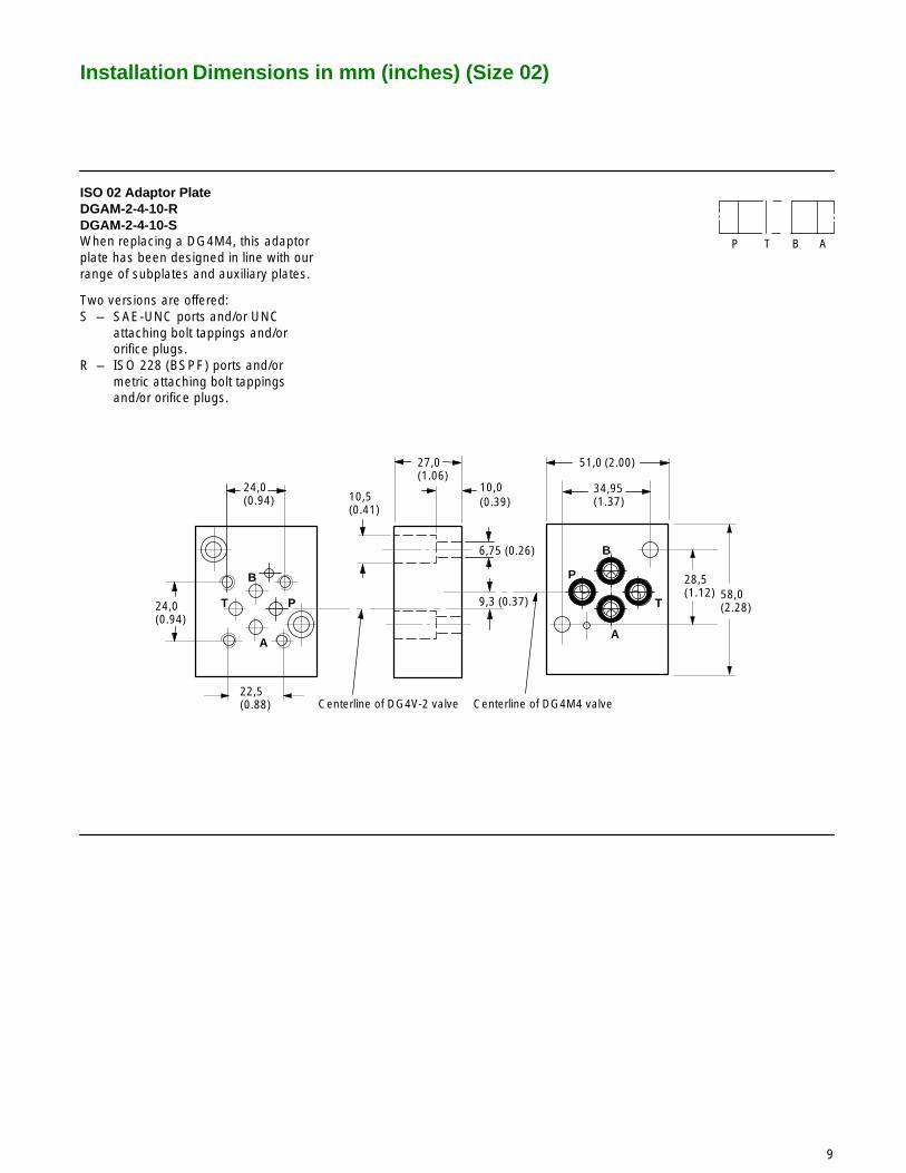
ISO 02 Adaptor Plate DGAM-2-4-10-RDGAM-2-4-10-SWhen replacing a DG4M4, this adaptorplate has been designed in line with ourrange of subplates and auxiliary plates.
Two versions are offered:S – SAE-UNC ports and/or UNC
attaching bolt tappings and/or orifice plugs.
R – ISO 228 (BSPF) ports and/or metric attaching bolt tappings and/or orifice plugs.
Installation Dimensions in mm (inches) (Size 02)
P T B A
Size 2
Size 3
23,25(0.92)
Ø 5,75(0.226 dia.)
46,0 (1.81)
60,0(2.36)
A
B
T P24,0(0.95)
7,0 (0.28)
22,5(0.88)
0.75(0.03)
4,25(0.17)
23,0(0.9)
10,0(0.39)
Ø 10,0(0.39 dia.)
48,0 (1.9)
32,5(1.279)
6,75(0.26)
40,5(1.59)
31,0(1.22)
0,75(0.03)
P
B
T
A
4 holes for valve mounting bolts (see table)
Size 02 Mounting Face Size 03 Mounting Face(ISO 4401 Size 03)
9,75 (0.38)
T BAP
75,0 (2.95)
62,0 (2.44)
75,0(2.95)
62,0(2.44)
6,5(0.26)6,5
(0.26)
P T
B
A
4 holes for valve mounting bolts (see table)
18,5(0.73)
Ø 5,75(0.226 dia.)
34,5(1.36)
Ø 10,0(0.39 dia.)
4 ports (see table)
20,0(0.78)
Model codestamped here
10
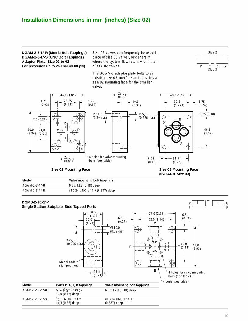
DGAM-2-3-1*-R (Metric Bolt Tappings)DGAM-2-3-1*-S (UNC Bolt Tappings)Adaptor Plate, Size 03 to 02 For pressures up to 250 bar (3600 psi)
Size 02 valves can frequently be used inplace of size 03 valves, or generallywhere the system flow rate is within thatof size 02 valves.
The DGAM-2 adaptor plate bolts to anexisting size 03 interface and provides asize 02 mounting face for the smallervalve.
Model Valve mounting bolt tappings
DGAM-2-3-1*-R M5 x 12,3 (0.48) deep
DGAM-2-3-1*-S #10-24 UNC x 14,9 (0.587) deep
DGMS-2-1E-1*-*Single-Station Subplate, Side Tapped Ports
Model Ports P, A, T, B tappings Valve mounting bolt tappings
DGMS-2-1E-1*-R G3/8 (3/8� BSPF) x12,0 (0.47) deep
M5 x 12,3 (0.48) deep
DGMS-2-1E-1*-S 3/4� 16 UNF-2B x 14,3 (0.56) deep
#10-24 UNC x 14,9(0.587) deep

Installation Dimensions in mm (inches) (Size 02)
PT
B1 A1
P1 T1 B1 A1
B2 A2
P2 T2 B2 A2
Valve station 1 Valve stations 2-3
PT
B1 A1
P1 T1 B1 A1
B6 A6
P6 T6 B6 A6
Valve station 1 Valve stations 2-6
37,5(1.47)
74,5 (2.93)
75,0(2.95)
6,0(0.24)
P
T37,5(1.47)
B
A
37,5(1.47)
37,5(1.47)
37,5(1.47)
2 ports P and T on all models,tapped per model code,(see table 2)
4 holes per station for valvemounting bolts, tapped permodel code (see table 3)
32,8(1.29)
PT
A
P
T
2 holes for attaching bolts,tapped per model type(see table 3)
2 ports, P and T through drilledend-to-end, tapped per modelcode (see table 2)
37,5(1.47)
60,0(2.36)
20,0(0.78)
Ø 10,0(0.39 dia.)
34,5(1.36)
20,25(0.8)
40,0(1.57)
17,25(0,68)
A and B ports at each station, tapped permodel code (see table 2)
Model codestamped here
B
Ø 5,75(0.226dia. thru)
PT
A
BPT
A
BPT
A
B
A
B
11
DGMS-2-*E-1*-* Multi-Station Subplates(4-station model illustrated)
Table 1: Dimensions
Model A B
DGMS-2-2E-1*-*DGMS-2-3E-1*-*DGMS-2-4E-1*-*DGMS-2-5E-1*-*DGMS-2-6E-1*-*
102 (4.02)140 (5.5)178 (7.0)216 (8.5)254 (10.0)
90 (3.54)125 (4.92)165 (6.5)200 (7.9)240 (9.45)
Table 2: Port TappingsModel Ports P, T Ports A, B
DGMS-2-1E-1*-R G1/2 (1/2� BSPF) G3/8 (3/8� BSPF) x 12,0 (0.47) deep
DGMS-2-1E-1*-S 3/4�-16 UNF-2B 3/4�-16 UNF-2B x 14,3 (0.56) deep
Table 3: Mounting Bolt TappingsModel Valve mounting bolts Manifold rear-mount holes
DGMS-2-1E-1*-R M5 x 12,3 (0.48) deep M8 x 1,25-6H
DGMS-2-1E-1*-S #10-24 UNC x 14,9 deep 5/16�-18 UNC-2B

Mounting Surfaces to ISO 4401 (Size 03)
4 holes, M5-6H x 12 (0.47)min. full thread depth n
4 ports Ø 6,3 (0.25 dia).For all Vickers size 03 valvesthis diameter may be increasedto Ø 7,5 (0.29)
Ø 4,0 x 4,3 min. depth (0.16 dia x 0.17)for locating pin
30,2(1.18)
21,5(0.85)
12,7(0.5)
0,75 �0,1 (0.03 �0.004)
48(1.89)min.
25,9 (1.01)15,5 (0.61)
5,1 (0.20)
7,5 (0.29)
40,5 �0,1(1.59 �0.004)
70 (2.75) min.
A
B
P
T
31,75 �0,1 (1.25 �0.004)
31,0 �0,1 (1.22 �0.004)
� #10-24 UNC-2B optional.
Interface with Additional Drain PortThe interface conforms to Vickersstandard, plus hole “L”
Typically used for proportional andother valves requiring an additionaldrain port, e.g.:KFDG4V-3KFTG4V-3KSDG4V-3
46,5 (1.83)
25,3(0.99)
Ø 4,0 (0.16 dia)
L
12
Vickers Standard Size 03 InterfaceThis interface conforms to:ISO 4401-03-02-0-94plus location pin holeANSI/B93.7M (and NFPA) size 03CETOP R35H4.2-4-03, plus location pin holeDIN 24340 Form A6 plus location pin hole

Installation Dimensions in mm (inches) (Size 03)
4 holes Ø 5,6 (0.22 dia) counterbored to Ø 9,5 (0.374 dia)
Nameplate
10,0 (0.4)
22,0 (0.9)
24,4 (1.0)46,0(1.8)
73,0 (2.9)
A
P
B
T
P AT B
DGMA-3-C*-1* Crossover PlateThe sealing faces shown are for11-design. For 10-design the sealingface is the same as for DGMA-3-B-1*(transfer passages are drilled). Ensurecorrect design number is quoted whenordering spare seals.
4 holes Ø 5,6 (0.22 dia) counterbored to Ø 9,5 (0.374 dia)
10,0 (0.4)
22,0 (0.9)
46,0(1.8)
Nameplate
DGMA-3-C2-1*DGMA-3-C1-1*
A
P
B
T
A
P
B
T
P AT B
P AT B
75,0(3.0)
48,5(1.9)
13
DGMA-3-B-1* Blanking Plate

Installation Dimensions in mm (inches) (Size 03)
4 holes Ø5,6 (0.22 dia)
Nameplate
20,0 (0.78)
75,0 (3.0)
2 tapped ports:For DGMA-3-T1-1*-B, G1/8 (1/8� BSPF)For DGMA-3-T1-2*-S, 7/16�-20 UNF-2B(SAE) (for 1/4� O.D. tubing)
46,0(1.8)
48,4(1.9)
AP
B
T
P AT B
B A
4 holes Ø5,6 (0.22 dia)
Nameplate
20,0 (0.78)
75,0 (3.0)
DGMA-3-T2-**-1* Tapping Plate, Ports P and T
2 tapped ports:For DGMA-3-T2-1*-B, G1/8 (1/8� BSPF)For DGMA-3-T2-2*-S, 7/16�-20 UNF-2B(SAE) (for 1/4� O.D. tubing)
46,0(1.8)48,4(1.9)
A
P
B
T
P AT B
P T
14
DGMA-3-T1-**-1* Tapping Plate, Ports A and B

Installation Dimensions in mm (inches) (Size 03)
L
A
B
PTA
B
P T
P AT B P AT B
PT
AB
L
4 system connections for rear-entry models, see table
4 system connections for side-entry models, see table
Rear mountingface
4 holes Ø 5,6 (0.22 dia)spotfaced to Ø 13,0 (0.51 dia)
4 holes tapped according to model type (see table):For models with BSPF ports, M5-6H x 12 (0.47) deepFor models with SAE ports, #10-24 UNC-2B x 12,7 (0.5) deep
84,0(3.3)
84,0(3.3)
72,0(2.83)
15,75(0.62)
6,0(0.24)
6,0(0.24)
19,75(0.78)
72,0(2.83)
16,0(0.63)
35,0(1.38)
20,0(0.79)
16,3(0.64)
59,25(2.33)
12,75(0.5)
12,75(0.5)
35,0(1.38)
57,25(2.25)
Port L (see KDGVM-3 models in table)s
36,0(1.42)
15
Single-Station Subplates, Rear and Side Tapped Ports
Port Threads
Model Ports P, T, A, BAt rear or side
Port L
BSPF ports/M5 mounting bolts:
DGVM-3-1*-R Rear G3/8� (3/8� BSPF) x 12,0 (0.47) deep –
KDGVM-3-1*-R Rear G3/8� (3/8� BSPF) x 12,0 (0.47) deep G1/8� (1/8� BSPF) x 12,0 (0.47) deep
DGMS-3-1E-1*-R Side G3/8� (3/8� BSPF) x 12,0 (0.47) deep –
SAE ports/#10-24 UNC mounting bolts:
DGVM-3-1*-S Rear 3/4�-16 UNF-2B x 14,3 (0.56) deep (SAE) –
KDGVM-3-676803-1* Rear 3/4�-16 UNF-2B x 14,3 (0.56) deep (SAE) 7/16�-20 UNF-2B x 11,6 (0.46) deep (SAE)
DGMS-3-1E-1*-S Side 3/4�-16 UNF-2B x 14,3 (0.56) deep (SAE) –
DGMS-3-1EY-1*-S Side 5/8�-18 UNF-2B x 12,7 (0.5) deep (SAE) –
s 11,5 (0.45) from rear mounting face to port center line.

Installation Dimensions in mm (inches) (Size 03)
70,0(2.75)
14,2(0.56)
28,4(1.12)
21,0(0.83)
90,4(3.56)
54,0(2.12)
0,75(0.03)
12,0(0.47)
46,0(1.81)
31,75(1.25)
40,5(1.59)
5,3(0.21)
4 holes Ø 7,1 (0.281 dia),counterbored Ø 11,1 (0.438 dia) �
4 holes tapped:For DGAM-3-01-1*-R, M5-6H x 12 (0.47) deepFor DGAM-3-01-1*, #10-24 UNC-2B x 12,7 (0.5) deep
PA
T
B
P
A
B
TB
TA
Standard T port
Additional T port
Size 03 Mounting Surface Size 05 Mounting SurfaceSeals included
n Supplied complete with bolts for mounting to size 05 interface:M6 bolts with type DGAM-3-01-1*-R1/4�-20 UNC bolts with type DGAM-3-01-1*.
P ATA B
P AT BSize 03
Size 05TB
31,0(1.22)
18,3 (0.72)
16
DGAM-3-01-1*-R (Metric Bolt Tappings)DGAM-3-01-1* (UNC Bolt Tappings)Adaptors, Size 05 to 03For pressures up to 210 bar (3000 psi)Size 3 valves can frequently be used inplace of size 5 valves, typically for pilotcontrol functions, or generally wheresystem flow rate is within that of the size3 valves.
The DGAM-3-01 adaptor bolts n to anexisting size 05 interface and provides asize 03 mounting face for the smallervalve.

Installation Dimensions in mm (inches) (Size 03)
A
B
PT
A
B
PT
A
B
PT
At each station, 4 holes tappedaccording to model type (see table):For models with BSPF ports,M5-6H x 12,0 (0.47) deep.For models with SAE ports, #10-24UNC-2B x 12,7 (0.5) deep.
A and B ports at each station tapped accordingto model type:For DGMS-3-*E(X)-1*-R: G3/8 (3/8� BSPF)For DGMS-3-*E(X)-1*-S: 3/4�-16 UNF-2B (SAE)
2holes Ø 5,6 (0.22 dia)counterbored to Ø 11,1 (0.438 dia)
50,0(1.97)
50,0(1.97)
35,0(1.38)
A
B
38,0(1.5)
15,0(0.6)
60,0(2.36)effectivebolt length
38,0 (1.5) 68,0(2.68)
15,0 (0.6)
A
B
P
T
6,0(0.24)
P
T
P and T ports tapped according to model type:For DGMS-3-*E(X)-1*-R: G1/2 (1/2� BSPF)For DGMS-3-*E(X)-1*-S: 3/4�-16 UNF-2B (SAE)
34,0(1.34)
68,0(2.68)
These two ports are:Present in 4-, 5- and 6-station modelsOptional in 2- and 3-station models, by specifyingDGMS-3-2EX-1*-* orDGMS-3-3EX-1*-* respectively
P1 A1T1 P2 A2T2 B2
PT
PuTu
B1
A1 A2B2B1
Valve station 1 Valve stations 2 to 6
� Through-connection P and T ports on typesDGMS-3-2EX-1*-* and DGMS-3-3EX-1*-*
17
DGMS-3-*E(X)-1*-* Multi-Station Subplates(3-station model illustrated)
Model A B
DGMS-3-2E(X)-1*-*DGMS-3-3E(X)-1*-*DGMS-3-4E-1*-*DGMS-3-5E-1*-*DGMS-3-6E-1*-*
121 (4.8)171 (6.8)221 (8.7)271 (10.7)321 (12.7)
108 (4.25)158 (6.22)208 (8.19)258 (10.15)308 (12.12)

Mounting Surfaces to ISO 4401 (Size 05)
Interface with Additional Drain PortThe interface conforms to Vickersstandard, plus hole “L”
Typically used for proportional andother valves requiring an additionaldrain port, e.g.:KFDG4V-5KFTG4V-5
4 holes, M6-6H x 16 (0.63)min. full thread depth �
5 ports Ø 11,2 (0.44 dia)including optional tank port
37,3(1.47)
27,0(1.06)
16,7(0.66)
69,0(2.72)min.
21,4 (0.84)
6,3 (0.25)
3,2(0.12)
50,8(2.0)
46,0 �0,1(1.81 �0.004)
32,5 (1.28)
90,0 (3.54) min. Optional port (TB)
P
A B
TA TB
P
A B
TA TB
0,5 (0.02)
11,0 (0.433)
L
Ø 3,0 (0.12 dia)
P
A B
TA TB
62,0(2.44)
8,0(0.315)11,0
(0.433)
X Y
2 holes Ø 6,3 (0.25 dia) max.
Interface with Additional Pilot Ports X and YThe interface conforms to Vickersstandard, plus holes X and YISO 4401-05-05-0-94
Typically used for two-stage directionaland proportional control valves requiringadditional pilot ports, e.g.:DG5V-5KDG5V-5KFDG5V-5KHDG5V-5
54,0 �0,1(2.12 �0.004)
n 1/4�-20 UNC-2B optional.
18
Vickers Standard Size 05 InterfaceThis interface conforms to:ISO 4401-05-04-0-94ANSI/B93.7M (and NFPA) size 05CETOP R35H4.2-05DIN 24340 Form A10

Installation Dimensions in mm (inches) (Size 05)
P
A B
TA TB
4 holes Ø 7,14 (0.28 dia)
DGMA-5-C*-1* Crossover Plate
P TATB B A
P TATB B A
P TATB B A
70,0(2.8)
2,0 (0.08) sealplate37,0(1.46)
116,0(4.6)
72,0(2.84)
P
A B
TA
4 holes Ø 7,14 (0.28 dia)
70,0(2.8)
2,0 (0.08) sealplate37,0(1.46)
116,0(4.6)
72,0(2.84)
AB
TB
Nameplate
Nameplate
Plugs each end, G1/2 (1/2� BSPF)
5,0(0.2)
5,0(0.2)
19,5(0.77)
19
DGMA-5-B-1* Blanking Plate
Model Dimension A Dimension B
DGMA-5-C1-1*DGMA-5-C2-1*
25,0 (1.0)40,0 (1.6)
40,0 (1.6)25,0 (1.0)

Installation Dimensions in mm (inches) (Size 05)
P
A B
TA TB
4 holes Ø 7,14 (0.28 dia)
70,0(2.8)
2,0 (0.08) sealplate37,0(1.46)
116,0(4.6)
72,0(2.84)
31,0(1.2)
18,0 (0.71)
2 ports, G1/2 (1/2� BSPF)
Nameplate
Ports A and B are tapped M12 x 14 (0.55) deep(e.g. for orifice plugs) on opposite face to sealplate.
P TATB B A
P
A B
TA TB
DGMA-5-T2-1*-B Tapping PlatePorts P and T
4 holes Ø 7,14 (0.28 dia)
70,0(2.8)
2,0 (0.08) sealplate37,0(1.46)
116,0(4.6)
72,0(2.84)
Nameplate
28,0(1.1)
18,0(0.71)
2 ports, G1/2 (1/2� BSPF)45,0(1.8)
Ports P and TA are tapped M12 x 14 (0.55) deep(e.g. for orifice plugs) on opposite face to sealplate.
P TATB B A
20
DGMA-5-T1-1*-B Tapping PlatePorts A and B

Installation Dimensions in mm (inches) (Size 05)
A B
TA TB
4 holes Ø 7,14 (0.28 dia)
70,0(2.8)
2,0 (0.08) sealplate37,0(1.46)
116,0(4.6)
Nameplate
31,0(1.2)
18,0(0.71)
3 ports, G1/2 (1/2� BSPF)
Ports P, A and B are tapped M12 x 14 (0.55) deep(e.g. for orifice plugs) on opposite face to sealplate.
P
72,0(2.84)
P TATB B A
DGAM-5-1*-*, X and Y Port Adaptor PlatesProvides for external connections toadditional pilot ports X and Y when theseports are not present in subplate/manifoldblock. Typically used for two-stagedirectional and proportional valves:DG5V-5KDG5V-5KFDG5V-5KHDG5V-5
P
A B
TA TB
4 holes Ø 7,14 (0.28 dia)
70,0(2.8)
32,0(1.25)
102,0(4.0)
72,0(2.84)44,0
(1.7)
Nameplate
YX
P TATB B A
“X” and “Y” ports, see table
X Y
21
DGMA-5-T3-1*-B Tapping PlatePorts P, A and B
Model “X” and “Y” port thread
DGAM-5-1*-RDGAM-5-1*-S
G1/4 (1/4� BSPF) x 11,0 (0.43) full thread depth 9/16�-18 UNF x 12,7 (0.5) full thread depth

Installation Dimensions in mm (inches) (Size 05)
PT
AB
PA
BT
23,1(0.9)
38,1(1.5)
101,6 (4.0)
39,6(1.6)
12,7(0.5)
79,4 (3.12)
47,7(1.9)
68,3(2.7)
23,1 (0.9)
18,3(0.6)
69,0(2.7)
4 holes Ø 10,8 (0.42 dia) through,spotfaced Ø 17,5 (0.66 dia)
4 ports P, A, B, T: 3/4� -16 UNF-2Bx 14,3 (0.56) full thread depth
4 holes tapped 1/4� -20 UNC-2B x12,7 (0.5) deep
91,95(3.62) 114,3
(4.5)
33,0(1.3)
P
B
A
T47,7(1.9)
22
Subplate with Side Ports P, T, A, BMaximum Pressure 210 bar (3000 psi)Model type: DGSME-01-2*-T8

Installation Dimensions in mm (inches) (Size 05)
11,5(0.45)
P
A B
T
N
M
101,6 (4.0)12,7(0.5)
79,4 (3.12)
68,3(2.7)
23,1(0.9)
11,2(0.44)
4 holes Ø 10,8 (0.42 dia) through,spotfaced Ø 17,5 (0.66 dia)
4 holes tapped according to model type:For DGSM-01 and KDGSM-5 models (UNC port threads),1/4� -20 UNC-2B x 12,7 (0.5) deep.For EDGSM-01(*) and EKDGSM-01Y models (BSPF port threads),M6-6H x 15,8 (0.62) deep.
92,1(3.62)
114,3(4.5)
P T B A
P T B A L
L
P T B A
L
WK E
69,0(2.7)
F
68,3(2.7) 47,5
(1.5)
C
H
J
G
90,4(3.56)
5,6(0.22)
Side port L, EKDGSM-01Y only:9/16� -18 UNF-2B x 12,7 (0.5)full thread depth
Rear port L, KDGSM-5-676805 only:G1/8 (1/8� BSPF) x 12,0 (0.47) full thread depth
11,2 (0.44)
23
Subplates with Rear Ports P, T, A, BMaximum Pressure 210 bar (3000 psi)Model types: DGSM-01-2*-T8
KDGSM-5-676805-2* (with rear port L)
Maximum Pressure 280 bar (4000 psi)Model types: EDGSM-01-1*-R
EDGSM-01X-1*-REDGSM-01Y-1*-REKDGSM-01Y-1*-R (with side port L)
Ports P, T, A, B Threads
Model Port thread
210 bar (3000 psi)DGSM-01-2*-T8KDGSM-5-676805-2*
3/4�-16 UNF-2B x 14,0 (0.56) full thread depth
280 bar (4000 psi)EDGSM-01-1*-R G1/4 (1/4� BSPF) x 12,2 (0.48) full thread depth
EDGSM-01X-1*-R G3/8 (3/8� BSPF) x 12,2 (0.48) full thread depth
EDGSM-01Y-1*-REKDGSM-01Y-1*-R G1/2 (1/2� BSPF) x 15,0 (0.59) full thread depth
DimensionsModel C E F G H J K M N W
210 bar (3000 psi)DGSM-01-2*-T8KDGSM-5-676805-2* 45,2 (1.78) 42,1 (1.66) 19,0 (0.75) 68,3 (2.69) 45,2 (1.78) 23,8 (0.94) 42,1 (1.7) 31,8 (1.25) 23,9 (0.94) 57,1 (2.25)
280 bar (4000 psi)EDGSM-01-1*-R 39,7 (1.56) 38,1 (1.5) 13,5 (0.53) 65,5 (2.58) 41,7 (1.64) 10,3 (0.41) 40,9 (1.61) 31,8 (1.25) 23,9 (0.94) 62,7 (2.47)
EDGSM-01X-1*-R 39,7 (1.56) 40,5 (1.59) 13,5 (0.53) 67,5 (2.66) 39,7 (1.56) 12,7 (0.5) 40,5 (1.59) 31,8 (1.25) 23,9 (0.94) 68,6 (2.7)
EDGSM-01Y-1*-R 39,7 (1.56) 40,5 (1.59) 9,9 (0.39) 70,6 (2.78) 39,7 (1.56) 10,7 (0.42) 40,5 (1.59) 31,8 (1.25) 28,6 (1.13) 72,6 (2.86)
EKDGSM-01Y-1*-R 39,7 (1.56) 40,5 (1.59) 9,9 (0.39) 70,6 (2.78) 39,7 (1.56) 10,7 (0.42) 40,5 (1.59) 36,5 (1.44) 28,6 (1.13) 72,6 (2.86)
Installation Dimensions in mm (inches) (Size 05)
LP T B A
P
A B
T
89,0 (3.5)
80,0 (3.15)
67,0(2.6)
4 holes M6 x14,0 (0.55) fullthread depth
115,0(4.6)L
46,0(1.81)
77,5(3.1)
88,0 (3.5)
Port L, G1/4 (1/4� BSPF) x 12,0 (0.47),spotfaced to Ø 24,0 (0.94 dia)
120,0 (4.8)
23,0(0.9)
92,0(3.62)
17,0(0.7)
47,5(1.9)
12,5 (0.5)
Z Y
42,0(1.7)
Port L, Ø 4,0 (0.16 dia)
Ports P, T, A, B,Ø 10,5 (0.41 dia)
Part Section A-A
40,0(1.6)
5,0(0.2) A
A
Recommended panelcut-out to clear fittings,Ø 108,0 (4.25 dia)
75,0(3.0)
4 holes Ø 10,5 (0.41 dia)
13,0(0.51)
1,0 (0.04)
24
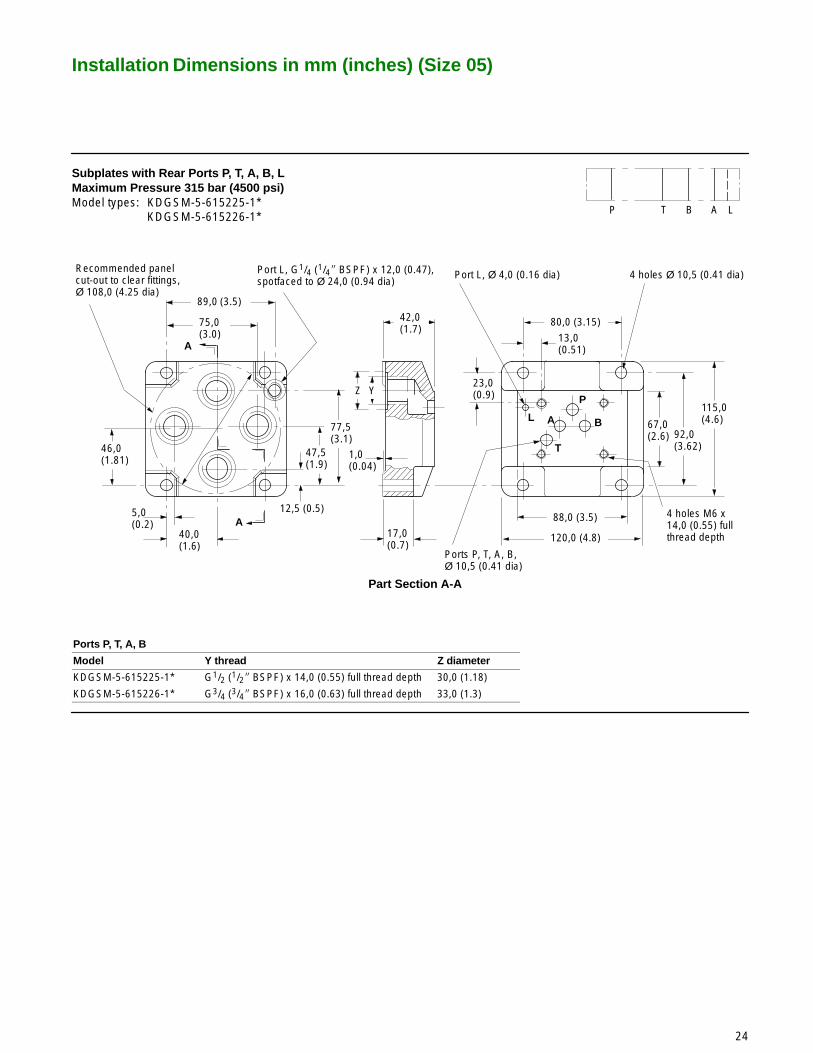
Subplates with Rear Ports P, T, A, B, LMaximum Pressure 315 bar (4500 psi)Model types: KDGSM-5-615225-1*
KDGSM-5-615226-1*
Ports P, T, A, B
Model Y thread Z diameter
KDGSM-5-615225-1* G1/2 (1/2� BSPF) x 14,0 (0.55) full thread depth 30,0 (1.18)
KDGSM-5-615226-1* G3/4 (3/4� BSPF) x 16,0 (0.63) full thread depth 33,0 (1.3)
Installation Dimensions in mm (inches) (Size 05)
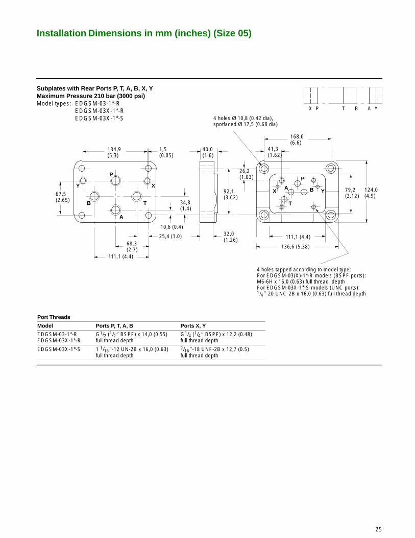
41,3(1.62)
P
A B
T
134,9(5.3)
4 holes tapped according to model type:For EDGSM-03(X)-1*-R models (BSPF ports):M6-6H x 16,0 (0.63) full thread depthFor EDGSM-03X-1*-S models (UNC ports):1/4�-20 UNC-2B x 16,0 (0.63) full thread depth
92,1(3.62)
67,5(2.65)
111,1 (4.4)
YX P T B A
168,0(6.6)
40,0(1.6)
124,0(4.9)
26,2 (1.03)
79,2(3.12)
136,6 (5.38)
32,0(1.26)
25,4 (1.0)68,3(2.7)
111,1 (4.4)
34,8 (1.4)
10,6 (0.4)
X Y
4 holes Ø 10,8 (0.42 dia),spotfaced Ø 17,5 (0.68 dia)
1,5(0.05)
XY
A
B T
P
25
Subplates with Rear Ports P, T, A, B, X, YMaximum Pressure 210 bar (3000 psi)Model types: EDGSM-03-1*-R
EDGSM-03X-1*-REDGSM-03X-1*-S
Port Threads
Model Ports P, T, A, B Ports X, Y
EDGSM-03-1*-REDGSM-03X-1*-R
G1/2 (1/2� BSPF) x 14,0 (0.55) full thread depth
G1/4 (1/4� BSPF) x 12,2 (0.48) full thread depth
EDGSM-03X-1*-S 1 1/16�-12 UN-2B x 16,0 (0.63) full thread depth
9/16�-18 UNF-2B x 12,7 (0.5) full thread depth

Mounting Surfaces to ISO 4401 (Sizes 07 and 08)
2 holes Ø 4,0 (0.157 dia)x 8,0 (0.31) min. depth
4 holes M10 x 17,0 (0.67)min. full thread depth �
2 holes M6-6H x 17,0 (0.67)min. full thread depth �
3 holes (ports L, X, Y)Ø 6,3 (0.25 dia) max. 4 holes (ports P, T, A, B)
Ø 17,5 (0.69 dia) max.
95,0(3.74)min.
130,0 (5.12) min.
18,3(0.72)
34,1(1.34)
50,0(1.97)
65,9(2.59)
76,6(3.016)
88,1(3.47)
101,6 �0,1(4.0 �0.004)
1,6 �0,1(0.063 �0.004)
14,3 (0.56)
15,9 (0.63)
71,5 �0,1(2.815�0.004)
PT
A B
X
Y
L
11,0(0.43)
69,8 �0,1(2.75�0.004)
57,2(2.25)
55,6(2.19)
34,9 (1.38)
n 3/8�-16 UNC optional.� 1/4�-20 UNC optional.
2 holes Ø 7,5 (0.295 dia) x8,0 (0.31) min. depth
6 holes, M12-6H x 20,0 (0.78) min. full thread depth �
153,0 (6.02) min.
5,6 (0.22)
17,5 (0.689)
29,4 �0,1 (1.157 �0.004)
53,2 �0,1 (2.094 �0.004)
94,5 �0,1 (3.720 �0.004)
100,8 (3.968)
112,7 (4.437)
130,2 �0,1(5.126 �0.004)
77,0 (3.03)
92,1 �0,1(3.626�0.004)
74,6(2.937)
73,0(2.874)
46,0(1.181)
19,0 (0.748)
17,4 (0.685)
118,0(4.65)min.
4,8 �0,1 (0.189 �0.004)
Ports X,Y:Ø 11,2 (0.44 dia) max.
Port L�:Ø 11,2 (0.44 dia) max.
Ports P, T, A, B:Ø 23,4 (0.92 dia) max.
PT
A BX
Y
L
Vickers Standard Size 08 InterfaceThis interface conforms to:ISO 4401-08-07-0-94ANSI/B93.7M (and NFPA) size 08CETOP R35H4.3-08DIN 24340 Form A25
� 1/2�-13 UNC optional.� Vickers uses port L for pressure-centered
and other options not in high demand.
26
Vickers Standard Size 07 InterfaceThis interface conforms to:ISO 4401-07-06-0-94ANSI/B93.7M (and NFPA) size 07CETOP R35H4.3-07DIN 24340 Form A16

Installation Dimensions in mm (inches) (Sizes 07 and 08)
P
TA
BX
Y
L
120,0(4.73)
160,0(6.3)
30,0 (1.18)
96,0(3.78)
13,0 (0.51)
35,0 (1.38)
60,0 (2.36)
75,0(2.95)
150,0(5.9)
140,0(5.51)
9,0 (0.35)
21,5 (0.85)
29,0 (1.14)
61,0(2.4)
60,0(2.36)
L
T
PB
A
Y
X
36,5(1.44) 52,5
(2.07) 91,5(3.6)
107,5(4.23)
6 tapped holes for valve mounting, see table
For port tappings according to modelcode, see table
4 holes Ø 9,0 (0.35 dia) through,spotfaced Ø 14,5 (0.57 dia)
184,0(7.25)
YX P T B AL
27
For up to 350 bar (5000 psi) Maximum PressureEDGVM-7Y-D-1*-R (BSPF port threads; metric mounting bolts)EDGVM-7Z-D-1*-S (UNF/SAE port threads; UNC mounting bolts)
Port and Bolt Threads
Model Ports P, T, A, B Ports L, X, Y Mounting bolt tapping
EDGVM-7Y-D-1*-R G1 (1� BSPF) x 19,0 (0.75) full thread depth G1/4 (1/4� BSPF) x 12,0 (0.47) full thread depth4 x M102 x M6
EDGVM-7Z-D-1*-S 115/16�-12 UN-2B x 19,0 (0.75) full thread depth 9/16�-18 UNF-2B x 12,7 (0.5) full thread depth4 x 3/8�-16 UNC2 x 1/4�-20 UNC

Installation Dimensions in mm (inches) (Sizes 07 and 08)
L
T P
BA
Y
X
For port tappings according to modelcode, see table
160,0(6.3)
69,9(2.75)
140,0(5.51)
12,6(0.5)
C
DE
M
K
J
H
G F
14,3 (0.65)
42,5 (1.67)
Ø 9,9 (0.389 dia)
25,0 (1.0)
Ø 14,5 (0.57 dia)
92,0(3.62)
EDGVM-7X OnlyDGSM-04 Only
89,0(3.5)
38,1(1.5)
35,0(1.38)
Ø 8,73 (0.344 dia)
YX P T B AL
28
For up to 210 bar (3000 psi) Maximum PressureDGSM-04-12S-2* (UNF/SAE port threads; UNC mounting bolts)
For up to 350 bar (5000 psi) Maximum PressureEDGVM-7X-D-1*-R (BSPF port threads; metric mounting bolts)
Port and Bolt Threads
Model Ports P, T, A, B Ports L, X, Y Mounting bolt tapping
DGSM-04-12S-2* 1 1/16�-12 UNF-2B x 19,1 (0.75) full thread depth 9/16�-18 UNF-2B x 12,7 (0.5) full thread depth4 x 3/8�-16 UNC2 x 1/4�-20 UNC
EDGVM-7X-D-1*-R G3/4 (3/4� BSPF) x 16,0 (0.63) full thread depth G1/4 (1/4� BSPF) x 12,0 (0.47) full thread depth4 x M102 x M6
Dimensions
Model C D E F G H J K M
DGSM-04-12S-2* 121,4 (4.78) 88,4 (3.48) 44,2 (1.74) 56,6 (2.23) 54,9 (2.16) 18,3 (0.72) 121,4 (4.78) 76,7 (3.02) 32,3 (1.27)
EDGVM-7X-D-1*-R 128,6 (5.06) 93,6 (3.68) 50,6 (1.99) 55,6 (2.19) 52,0 (2.05) 15,9 (0.63) 113,6 (4.47) 79,6 (3.13) 36,6 (1.44)
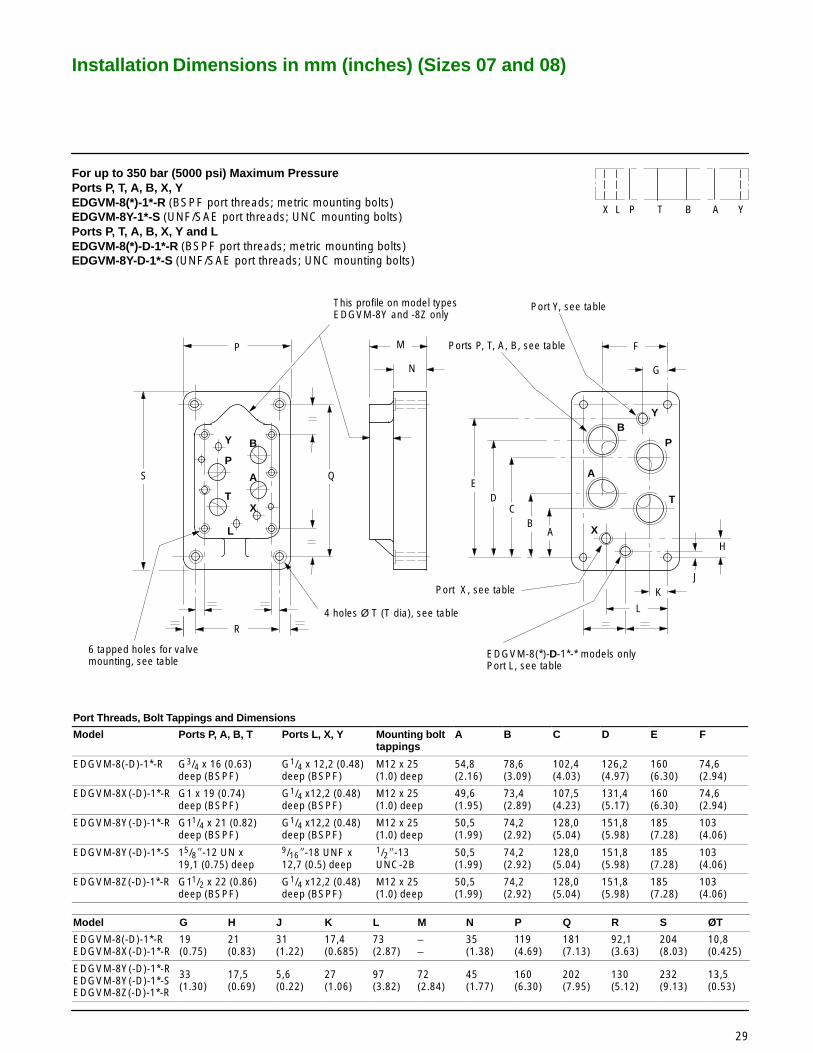
Installation Dimensions in mm (inches) (Sizes 07 and 08)
X
6 tapped holes for valve mounting, see table
4 holes Ø T (T dia), see table
R
B
T
P
A
Y
L
K
F
G
AB
CD
H
J
QS
P
E
M
N
This profile on model typesEDGVM-8Y and -8Z only
Port Y, see table
Ports P, T, A, B, see table
Port X, see table
EDGVM-8(*)-D-1*-* models onlyPort L, see table
Y B
A
L
T
P
X
YX P T B AL
29
For up to 350 bar (5000 psi) Maximum PressurePorts P, T, A, B, X, YEDGVM-8(*)-1*-R (BSPF port threads; metric mounting bolts)EDGVM-8Y-1*-S (UNF/SAE port threads; UNC mounting bolts)Ports P, T, A, B, X, Y and LEDGVM-8(*)-D-1*-R (BSPF port threads; metric mounting bolts)EDGVM-8Y-D-1*-S (UNF/SAE port threads; UNC mounting bolts)
Port Threads, Bolt Tappings and Dimensions
Model Ports P, A, B, T Ports L, X, Y Mounting bolttappings
A B C D E F
EDGVM-8(-D)-1*-R G3/4 x 16 (0.63) deep (BSPF)
G1/4 x 12,2 (0.48)deep (BSPF)
M12 x 25(1.0) deep
54,8 (2.16)
78,6 (3.09)
102,4(4.03)
126,2(4.97)
160(6.30)
74,6(2.94)
EDGVM-8X(-D)-1*-R G1 x 19 (0.74)deep (BSPF)
G1/4 x12,2 (0.48)deep (BSPF)
M12 x 25(1.0) deep
49,6(1.95)
73,4(2.89)
107,5(4.23)
131,4(5.17)
160(6.30)
74,6(2.94)
EDGVM-8Y(-D)-1*-R G11/4 x 21 (0.82)deep (BSPF)
G1/4 x12,2 (0.48)deep (BSPF)
M12 x 25(1.0) deep
50,5(1.99)
74,2(2.92)
128,0(5.04)
151,8(5.98)
185(7.28)
103(4.06)
EDGVM-8Y(-D)-1*-S 15/8�-12 UN x19,1 (0.75) deep
9/16�-18 UNF x12,7 (0.5) deep
1/2�-13UNC-2B
50,5(1.99)
74,2(2.92)
128,0(5.04)
151,8(5.98)
185(7.28)
103(4.06)
EDGVM-8Z(-D)-1*-R G11/2 x 22 (0.86)deep (BSPF)
G1/4 x12,2 (0.48)deep (BSPF)
M12 x 25(1.0) deep
50,5(1.99)
74,2(2.92)
128,0(5.04)
151,8(5.98)
185(7.28)
103(4.06)
Model G H J K L M N P Q R S ØT
EDGVM-8(-D)-1*-REDGVM-8X(-D)-1*-R
19(0.75)
21(0.83)
31(1.22)
17,4(0.685)
73(2.87)
––
35(1.38)
119(4.69)
181(7.13)
92,1(3.63)
204(8.03)
10,8(0.425)
EDGVM-8Y(-D)-1*-REDGVM-8Y(-D)-1*-SEDGVM-8Z(-D)-1*-R
33(1.30)
17,5(0.69)
5,6(0.22)
27(1.06)
97(3.82)
72(2.84)
45(1.77)
160(6.30)
202(7.95)
130(5.12)
232(9.13)
13,5(0.53)

Installation Dimensions in mm (inches) (Sizes 07 and 08)
54,9 (2.16)
P
T
A
B
X
17,5 (0.69)
73,0 (2.7)
35,0 (1.38)
114,0(4.5)
181,0(7.12)
203,0(8.0)
19,0(0.75) 74,6
(2.94)
138,2(5.44)
102,4(4.03)
92,0 (3.62)
42,9(1.69)
78,5(3.09)
126,2(4.97)
6 holes tapped 1/2�-13 UNC-2B
4 holes through Ø10,3 (0.406 dia)
Y
YX P T B AL
30
For up to 210 bar (3000 psi) Maximum PressurePorts P, T, A, B, X, YDGSM-8-1*-T** (UNF/SAE ports; UNC mounting bolts)
Port Threads
Model Ports P, T, A, B Ports X, Y
DGSM-8-1*-T12 11/16�-12 UN x 19,1 (0.75) deep 9/16�-18 UNF x 12,7 (0.5) deep
DGSM-8-1*-T16 15/16�-12 UN x 19,1 (0.75) deep 9/16�-18 UNF x 12,7 (0.5) deep