access to space study - ntrs.nasa.gov · the access to space study team began by recognizing that...
TRANSCRIPT
iNASA-TM-109693
U_
h- _ Lt_t_ _ _O
I ,-" 0
0 _ e- N
_ O
Ni..,4
l,JJ
l,.J ¢13<I: _'.0.
A
O_l-lf]
UJ
0Q.
_-_ ¢_
0 _
0 _ L
0 rO
!
I
f
National Aeronautics and
Space Administration
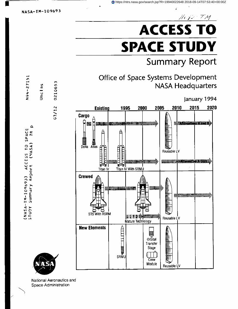
ACCESS TOSPACE STUDY
Summary Report
Office of Space Systems DevelopmentNASA Headquarters
January 1994
Existinl 1995 2000 2005 2010 2015 2020
Cargo c
E.,Delta Atlas
Reusable LV
Titan IV Titan IV With SRMU
Crew
STS With RSRM
E
_ _o..._,....
Reusable LV
SRMU
New Elements
Mature Technology
Orbital
Transfer
Stage
Crew
ModuleReusable LV
I
https://ntrs.nasa.gov/search.jsp?R=19940022648 2018-09-14T07:53:40+00:00Z


ACCESS TOSPACE STUDY
Summary Report
Office of Space Systems DevelopmentNASA Headquarters
January 1994


National Aeronautics and
Space Administration
Headquarters
Washington, DC 20546-0001
Reply toAttn of: DJAN 2 7 1994
TO:
FROM:
SUBJE CT:
A/Administrator
D/Associate Administrator for Space Systems Development
Access to Space Study
Enclosed is the final report on the Access to Space Study whichwas conducted during 1993.
It was my pleasure to lead the Study Team that enthusiastically
accepted your charter to identify and assess the majoralternatives for a long-range direction for space transportation
that would support all U.S. needs (civilian, commercial, andnational security) for several decades into the future.
The Study is also responsive to Congressional direction in the
Fiscal Year 1993 VA-HUD-Independent Agencies Appropriations
Bill to "... assess National launch requirements, potential
alternatives and strategies to address such needs ... to permit
formulation of multiyear program plans."
This Study is very timely. While its conclusions and
recommendations are based upon the ground rules and criteriaselected at the time, it will provide valuable input to the
decisions that the Administration intends to make this year on
U.S. launch strategy. It also establishes a strong basis for NASA
participation in the ongoing OSTP Space Transportation Working
Group and the DOD Launch Modernization Study.
Enclosure

ACCESS TOSPACE STUDY
Synopsis
This study was undertaken in response to a Congressional request in the NASA FY 1993
Appropriations Act. The request coincided with an on-going internal NASA broad reassess-
merit of the Agency's programs, goals, and long-range plans. Additional motivations for the
study included a recognition that while today's space transportation systems meet current
functional needs, they are costly and less reliable than desired, and lack desired operability.
This has resulted in increased costs to the government and in severe erosion of the ability of
U.S. industry to compete in the international space launch market. A further motivation is the
past failure of the Administration and Congress to reach consensus on developing moreefficient new launch systems.
This report summarizes the results of a comprehensive NASA in-house study to identify and
assess alternate approaches to access to space through the year 2030, and to select and
recommend a preferred course of action.
The goals of the study were to identify the best vehicles and transportation architectures to
make major reductions in the cost of space transportation (at least 50 percent), while at thesame time increasing safety for flight crews by at least an order of magnitude. In addition,
vehicle reliability was to exceed 0.98 percent, and, as important, the robustness, pad time,
turnaround time, and other aspects of operability were to be vastly improved.
This study examined three major optional architectures: (1) retain and upgrade the Space
Shuttle and expendable launch vehicles, (2) develop new expendable vehicles using conven-tional technologies and transition from current vehicles beginning in 2005, and (3) develop
new reusable vehicles using advanced technology, and transition from current vehicles
beginning in 2008. The launch needs mission model utilized for the study was based upon
today's projection of civil, defense, and commercial mission payload requirements.
Each of the three options resulted in a number of alternative architectures, any of which could
satisfy the mission model needs. After comparing designs and capabilities of the alternatives
within each of the three options, all defined to an equivalent depth using the same ground
roles, a preferred architectural alternative was selected to represent each option. These were
then compared and assessed as to cost, safety, reliability, environmental impact, and otherfactors.
The study concluded that the most beneficial option is to develop and deploy a fully reusable
single-stage-to-orbit (SSTO) pure-rocket launch vehicle fleet incorporating advanced tech-
nologies, and to phase out current systems beginning in the 2008 time period. While requiring
a large up-front investment, this new launch system is forecast to eventually reduce launch
costs to the U.S. Government by up to 80 percent while increasing vehicle reliability and
safety by about an order of magnitude. In addition, it would place the U.S. in an extremely
advantageous position with respect to international competition, and would leapfrog the
U.S. into a next-generation launch capability.
Thestudy determined that while the goal of achieving single-stage-to-orbit fully reusablerocket launch vehicles has existed for a long time, recent advances in technology make such
a vehicle feasible and practical in the near term provided that necessary technologies are
matured and demonstrated prior to start of vehicle development.
Major changes in acquisition and operations practices, as well as culture, are identified asnecessary in order to realize these economies. The study further recognized that the confident
development of such a new launch vehicle can only be undertaken after the required
technology is in hand. Therefore, the study recommended that a technology maturation anddemonstration program be undertaken as a first step. Such a program would require a
relatively modest investment for several years.
The study thus recommended that the development of an advanced technology single-stage-
to-orbit rocket vehicle become a NASA goal, and that a focused technology maturation anddemonstration be undertaken. Adoption of this recommendation could place the U.S. on a
path to recapture world leadership in the international satellite launch marketplace, as well
as enable much less costly and more reliable future government space activities.
ii

Table of Contents
Introduction ................................................................................................................ I
Purpose ......................................................................................................................... 2
Approach, Ground Rules, and Organization ........................................... 3
Description of the Option Teams' Analyses ............................................ 8
Option Team Down-Selects ............................................................................. 59
New Operations Concept ................................................................................. 61
Comparative Analysis .......................................................................................... 62
Observations and Conclusions ....................................................................... 69
Recommendations ................................................................................................ 72
°°.
111

Introduction
The 1993 NASA Appropriations Act included language that expressed Congress' concernabout the rising costs of the Space Station and space transportation, and the likelihood that
NASA's program budgets would, at best, be limited in the future. In view of these trends, the
Congress' concerns focused on NASA's ability to field a viable space program. Congress
requested that a study be performed to recommend improvements in Space Station Freedomand space transportation, and to examine and revalidate civilian and defense requirements for
space launch. This study was to be done in close cooperation with other agencies.
At about the same time, NASA independently undertook a series of internal studies as part
of a reassessment of the Agency's programs, goals, posture, and long-range plans. These
studies considered various options for the redesign of Space Station Freedom, Space Shuttle
safety and reliability improvements, alternative transportation systems, and others. Since the
Space Station Redesign Study developed into a full-fledged program reorientation activityduring 1993, space transportation emerged as the key remaining area of focus, being at the
heart of NASA's ability to support a wide range of national objectives and continue a
visionary civil space program.
Another major factor for this study's focus was that NASA, together with the Department of
Defense (DOD) and the aerospace industry, had spent nearly a decade defining and
advocating a new launch vehicle program (which culminated in the proposed NationalLaunch System), without being able to reach consensus with the Congress that it should be
developed.
Yet another factor was the continued erosion of the international market share for U.S. launch
vehicles. This market share has dropped from 100 percent to about 30 percent, largely due
to the development and fielding of the French-built Ariane system, which targeted and
captured at least 50 percent of the world's space launch market. U.S. industry has found itself
increasingly unable to effectively compete using the current generation of launch vehicles.
As a result of all these factors and trends, as well as the specific Congressional request, a
comprehensive in-house study was undertaken by NASA to identify and assess the majoralternatives for a long-range direction for space transportation. The scope of the study was
to support all U.S. needs for space transportation--including civilian, commercial, anddefense needs--for several decades into the future. This is the Access to Space Study, which
was recently completed and is summarized herein.
Access to Space Study--Summary Report 1

Purpose
The U.S. space transportation architecture meets the current needs for access to space. The
Space Shuttle is the world's most reliable launch system, and also functions as a human-
tended research laboratory and satellite deployment, retrieval, and repair facility. The
expendable launch vehicle fleet and related upper stages can lift all required defense andcommercial spacecraft to their required destinations.
While these systems are by no means dysfunctional, they have major shortcomings that will
only increase in significance in the future, and thus are principal drivers for seeking majorimprovements in space transportation.While the launch vehicles differ in their particular
characteristics, their aggregate shortcomings are well known. They are too costly, insuffi-
ciently reliable and safe, insufficiently operable, and increasingly losing market share to
international competition.
This study focused on identifying long-term improvements leading to a space transportation
architecture that would reduce the annual cost of space launch to the U.S. Government by atleast 50 percent, increase the safety of flight crews by an order of magnitude, and make major
improvements in overall system operability (turnaround time, schedule dependability,
robustness, pad time, and so forth). The study horizon was set at the year 2030 in order to
allow time for new vehicles using advanced technology to fairly demonstrate their potential.
Using these criteria, this study identifies options for a long-term direction for the U.S. to meetgovernment, defense, and commercial needs for space transportation, together with long-
range program plans for implementation. While the focus of the study is long term, it
recognizes that immediate improvements are needed. Therefore, program recommendations
identifying realistic near-term activities for transitioning to the long-term capability are alsoincluded.
2

Approach, Ground Rules,and Organization
ApproachThe Access to Space Study team began by recognizing that the Space Shuttle and the
expendable launch vehicle fleet represent a very large investment both in vehicles and theirsupporting infrastructure. It recognized, based on many past studies, that the replacement of
the current capability with any new vehicle or vehicles designed to overcome the above-
named shortcomings is likely to be an expensive and lengthy process.
Thus, the study approach considered, in parallel, a number of alternative approaches that
differ in the degree of replacement of current capability, in the pace at which current systems
are phased over to the new, and in the degree of utilization of new technologies. Three major
alternative options were defined:
1. Provide necessary upgrades to continue primary reliance on the Space Shuttle and the
current expendable launch vehicle (ELV) fleet through 2030.
2. Develop a new expendable launch system utilizing today's state-of-the-art technology,
and transition from the Space Shuttle and today's expendable launch vehicles startingin 2005.
3. Develop a new reusable advanced technology next-generation launch system, andtransition from the Space Shuttle and today's expendable launch vehicles starting in
2008.
This strategy and approach is illustrated in figure 1.
1995 2000 2005 2010 2015 2020 2025 2030
FIGURE1.--Study strategy and approach.
Access to Space Study--Summary Report
Each of the options was to treat the entire architecture of launch vehicles required. Each
would be analyzed by a separate study team working independently of the others. The
recommendations of tbese teams would be assessed by a small group reporting to the studydirector.
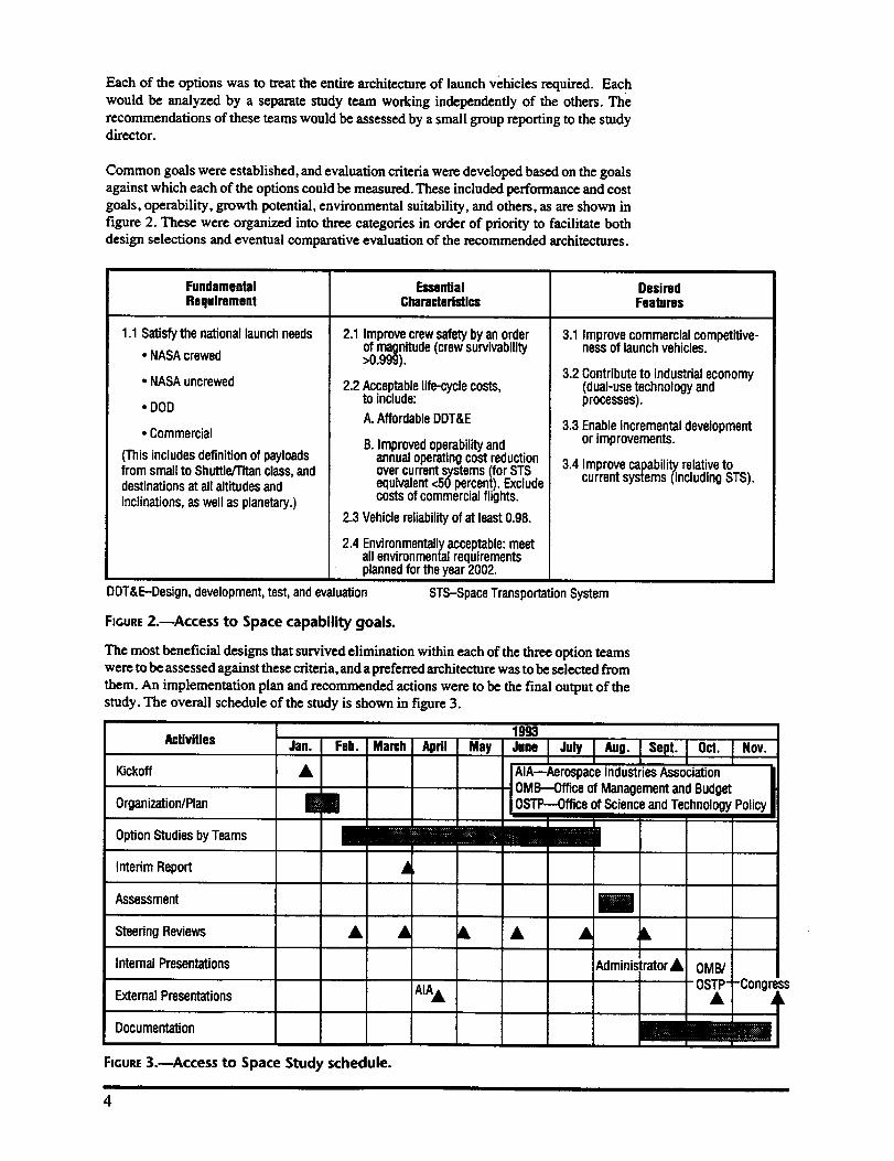
Common goals were established, and evaluation criteria were developed based on the goalsagainst which each of the options could be measured. These included performance and cost
goals, operability, growth potential, environmental suitability, and others, as are shown in
figure 2. These were organized into three categories in order of priority to facilitate bothdesign selections and eventual comparative evaluation of the recommended architectures.
Fundamental Essential DesiredRequirement Characteristics Features
3.1 Improvecommercialcompetitive-nessof launchvehicles.
1.1 Satisfy the nationallaunch needs
• NASAcrewed
• NASA uncrewed
• DOD
• Commercial
(Thisincludesdefinitionof payloadsfrom smallto Shuttle/Titanclass,anddestinationsat allaltitudes and
inclinations,as well as planetary.)
2.1 Improvecrewsafetybyan orderof magnitude(crewsurvivability>0.999).
2.2 Acceptablelife-cyclecosts,to include:
A.AffordableDDT&E
B. Improvedoperabilityandannualoperatingcost reductionovercurrentsystems(for STSequivalent<50 percent).Excludecostsof commercialflights.
2.3 Vehiclereliabilityof at least0.98.
2.4 Environmentallyacceptable:meetall environmentalrequirementsplannedfor theyear2002.
3.2 Contributeto industrialeconomy(dual-usetechnologyandprocesses).
3.3 Enableincrementaldevelopmentor improvements.
3.4 Improvecapabilityrelativetocurrentsystems(includingSTS).
DDT&E-Design,development,test, andevaluation STS-SpaceTransportationSystem
FIGURE2.--Access to Space capability goals.
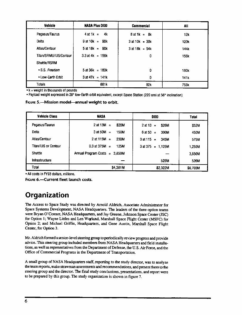
The most beneficial designs that survived elimination within each of the three option teams
were to be assessed against these criteria, and apreferred architecture was to be selected from
them. An implementation plan and recommended actions were to be the final output of thestudy. The overall schedule of the study is shown in figure 3.
Activities
Kickoff
Organization/Plan
OptionStudiesbyTeams
Interim Report
Assessment
SteeringReviews
InternalPresentations
Extemal Presentations
Documentation
Jan. Feb. March April May
|im
1993
"n' I "u"I m"""I I 0=°I '°v"AlA--Aerospace IndustriesAssociationOMB---Officeof ManagementandBudget
iOSTP---Officeof Scienceand TechnologyPolicy
4
AIA•Administrator• OM_
OSTP -Congr_
FIGURE3.---Access to Space Study schedule.
4

Ground Rules
A number of ground rules were established for the Access to Space Study. Since a Space
Station redesign was in progress, the Space Station Freedom design was utilized, but placedinto the Mir orbit of 220 nautical miles (nmi) circular altitude at 51.6 degrees inclination.
This was done to represent a worst-case scenario for the space transportation systems'
requirements.
A common mission model was defined that included all U.S. defense, civilian, and
commercial user elements covering the period from 1995 through 2030. This model was
based on conservative extrapolation of current requirements and planned programs, and did
not include major future possibilities such as exploration missions to the Moon and Mars.This mission model is shown in figure 4.
Vehicle Class NASA Commercial DOD
Pegasus/TaurusClass 2.0 1 Nominal+ 27 Growth
Delta Class 3.0 1 Nominal + 62 Growth
3 Nominal+0 Growth
Atlas Class 2.0
Titan Class 0.3 -- 3
Shuttle Class 8.0 -- --
15.3Total Launches5 Nominal+
9 Growth14
FIGURE4.mAnnual launch demand mission model from 1995 to 2030.
For lack of solid forecasts of future traffic, the model was assumed to be constant through
2030. It was recognized that such a fiat model was unlikely to endure over the long term and
that excursions would eventually have to be treated as better models became available, as
human exploration or other ambitious missions became better focused, or, hopefully, fromadditional market demand enabled by future reductions in the costs of access to space.
The annual payload weight to orbit represented by this model and the annual costs for currentlaunch vehicles to launch the model are shown in figures 5 and 6, respectively. The U.S.
Government launches 660,000 pounds of payload to space annually at a total cost of
$6.7B dollars.
Uniform costing guidelines were developed using conventional weight-based estimating
algorithms to allow direct comparison of all alternatives. It was recognized that innovative
and potentially lower cost strategies based on major management, contracting, and operating
changes might be considered by some, but not all, of the option teams. Therefore, it wasdecided that these changes were to be treated as excursions to the "business-as-usual" mode.
It was also decided that the commercial traffic estimates of the mission model were to be used
for fleet sizing and as a basis for estimating the production base. However, since the principal
study aim was to reduce launch costs to the government, the cost projections of the options
were to include only government-sponsored missions.
Access to Space StudymSummary Report 5
Vehicle NASAPlusDOD Commercial All
Pegasus/Taurus
De_
Atlas/Centaur
Titan/SRMU/IUS/Centaur
Shuttle/RSRM
• S.S. Freedom
• Low-Earth Orbit
4atlk = 4k
9atlOk = 90k
5at18k = 90k
3.3 at4k = 156k
5at36k = 180k
3at47k = 141k
8atlk = 8k
3atlOk = 30k
3at18k = 54k
0
12k
120k
144k
156k
180k
141k
Totals 661k 92k 753k
• k = weight in thousandsof pounds
• Payloadweightexpressedin28° low-Earthorbit equivalent,exceptSpace Station(220 nmiat 56= inclination)
FIGURE5.--Mission model--annual weight to orbit.
Vehicle Class
Pegasus/Taurus
Delta
Atlas/Centaur
Titan/IUS or Centaur
Shuttle
Infrastructure
Total
NASA
2 at 13M = $26M
3 at 50M = 150M
2 at 115M = 230M
0.3 at 375M = 125M
Annual ProgramCosts = 3,850M
• Allcosts in FY93dollars,millions.
FIGURE6.---Current fleet launch costs.
$4,381M
DOD
2 • 13 = $26M
6 _ 50 = 300M
3_ 115 = 345M
3at375 = 1,125M
526M
$2,322M
Total
$52M
450M
575M
1,250M
3,850M
526M
$6,703M
OrganizationThe Access to Space Study was directed by Arnold Aldrich, Associate Administrator for
Space Systems Development, NASA Headquarters. The leaders of the three option teamswere Bryan O'Connor, NASA Headquarters, and Jay Greene, Johnson Space Center (JSC)
for Option 1; Wayne Littles and Len Wqrlund, Marshall Space Flight Center (MSFC) for
Option 2; and Michael Griffin, Headquarters, and Gene Austin, Marshall Space FlightCenter, for Option 3.
Mr. Aldrich formed a senior-level steering group to periodically review progress and provideadvice. This steering group included members from NASA Headquarters and field installa-
tions, as well as representatives from the Department of Defense, the U.S. Air Force, and the
Office of Commercial Programs in the Department of Transportation.
A small group of NASA Headquarters staff, reporting to the study director, was to analyze
the team reports, make strawman assessments and recommendations, and present them to the
steering group and the director. The final study conclusions, presentations, and report were
to be prepared by this group. The study organization is shown in figure 7.
6

Director
A. Aldrich
ExecutiveSecretaryM Stein
L. Beach/LaRCJ. Greene/JSC
M. LyonsE. Sevin/DODL. Harris
Steering Group
W. Littles/IVlSFCG. Austin/MSFCM. GriffinB.O'ConnorD. Pine
Option 1
B O'Connor/J Greene
Orbiter• Coultas
Boosters• Darwin
Mission Operations• Nelson
Integration• Pace• Grush
Processing• Murphy
CostAnalysis• Simmonds• Costello
Advisors
W Murphy/KSCD Hard/USAF
D Trilling/DOGR McCormick/USAF
Option2
W Littles/L Worlund
Requirements• Armstrong• Richards
CargoTransferVehicle• Adams• Hueter
PersonnelLaunch• Eldred• Erwin
ELV/HLLVVehicles• Bachtel• ThreatCargoUp-Down• Hueter• Adams
IntegraUon/Costing/Evaluation
I. Bekey,D. Pine,L. Peach
Option3
M Griffin/G Austin
TechnologyAssessment• Schutzenhofer/Greenwood• Goldstein/Riccitiello
Adv Tech RocketVehicles• Powell• Cook• Smith
Operations• Blum• Ishmael
• Payton• McWhorter• Cabana
Interim ELV's• Williams
• Rockwell
• SpaceIndustries• Branscome• Oliver
• Sohwinghamer• Richards
HeadquartersSupport• Hudkins• McClung• Hedin
Architectures/Integration• Brady• Brown
ProgremmaUcs/Cost• Hamaker• Zoller
TechnologyReadiness• Worlund
EnvironmentalImpacts• Scwinghamer• McCaleb
Facilities
• Page• Guin• Eoff
ReviewCommittee• Harris • Huffstetler• Bridwell • Piland• Darwin • Peach
• McCarty • Nieberding
Costs• Creech• Wilson
Propulsion• Ryan• Meyer
Air-BreathingSystems• Couch• Hunt
TSTO
• Gregory• Burkardt
FIGURE7.reStudy organization--Access to Space.
Access to Space Study--Summary Report ?

Description of the
Option Teams' Analyses
The three option teams each characterized and analyzed a number of alternative vehicle
designs and vehicle architectural mixes. They eventually settled on a small number of
principal architectures to analyze in depth. These are shown in figure 8 in order to providean overview and perspective of the options teams' detailed activities.
Option1
Shuttle-Based
• Retrofit:Evolutionaryimprove-ments. Keepthe currentELVfleet.
Option 2 Option3
• New Build:Abovechangesplusmajor internal mods;neworbiter.Keepthe currentELVfleet.
• New Mold Line: Abovechangesplusmajorexternal mods;new orbitersand boosters.Keepthe currentELVfleet.
ConventionalTechnology
• 84 configurationswithdifferingcrewcarriers,cargovehicles,stageconfigurations,enginetypes,andnumberof newvehicles.Reducedto four primary candidatearchitectures:
- (2A): New largevehicle• KeepAtlas,DeltaELV's• HL-42 plus ATV
- (2B): New Ig. andsm. vehicle• KeepDeltaELV• CLV-Pfor crewplus cargo
- (2C): New Ig. andsm. vehicle• KeepDeltaELV• HL-42 plus ATV• Hybrids;STMEengines
- (2D): New Ig.andsm. vehicle• KeepDeltaELV• HL-42 plusATV• RD180/J2Sengines
New Technology
• Single-stage-to-orbit all rocket- With and W'_houtELV's
• Single-stage-to-orbitair-breather/rocket- No ELV's
• Two-stage-to-orbitair-breather/rocket- No ELV's
FIGURE8.--Principal architectural alternatives examined.
The results and recommendations of each option team arc presented below. The recommen-
dations of these option teams are assessed beginning in the Option Team Down-Selectssection, and study conclusions are then drawn.
Option 1 Team Analysis
ObjectivesThe premise of the overall Access to Space Study was that any design options that would
replace the Space Shuttle with equal capability would have a price tag on the order of
$10B or more. The challenge for Team 1 was to see what savings could be instilled in theSpace Shuttle Program through changes made to the hardware for a similar or smaller cost.
The study delved into all subsystems on the Space Shuttle vehicle and stressed interaction
between the Kennedy Space Center (KSC) operations representatives and the subsystem
engineers to address current vehicle design features that affect operability and cost.
The Option 1 team addressed hardware changes only. Contract and management structure
were not addressed, as it was felt that the mainline program is putting strong emphasis on thisaspect of the program and, to be effective, recommendations in this area must come from
within the program. However, the portion of the Space Shuttle budget that is directly affectedby the hardware is only about 30 percent. This situation thus limited the attainable cost
savings by Option I and emphasized the need for the program to continue making significantgains in program management.
8
It is recognized that the Space Shuttle Program has already implemented a management plan
in FY91 aimed toward reducing operations costs. These program-imposed target reductions
have a goal of reducing operations costs by 37 percent by FY96. As of FY94, the program
has achieved a 29 percent operating cost reduction against an FY92 baseline.
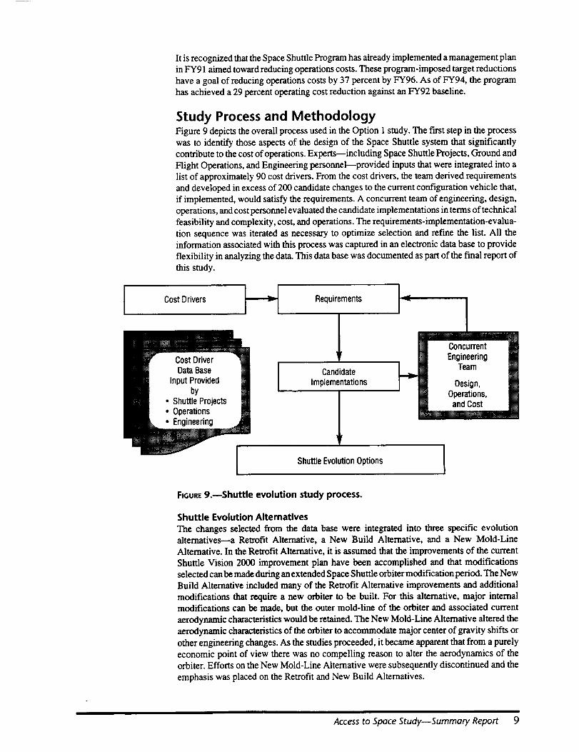
Study Process and MethodologyFigure 9 depicts the overall process used in the Option I study. The first step in the process
was to identify those aspects of the design of the Space Shuttle system that significantly
contribute to the cost of operations. Experts--including Space Shuttle Projects, Ground and
Flight Operations, and Engineering personnel--provided inputs that were integrated into a
list of approximately 90 cost drivers. From the cost drivers, the team derived requirements
and developed in excess of 200 candidate changes to the current configuration vehicle that,
if implemented, would satisfy the requirements. A concurrent team of engineering, design,operations, and cost personnel evaluated the candidate implementations in terms of technical
feasibility and complexity, cost, and operations. The requirements-implementation-evalua-tion sequence was iterated as necessary to optimize selection and refine the list. All the
information associated with this process was captured in an electronic data base to provide
flexibility in analyzing the data. This data base was documented as part of the final report of
this study.
Cost Drivers ]_ Requirements ]
1I CandidateImplementations
lu
[] Concurrent Ill[] Engineering []
I [] Design, []• [] Operations, []
andCost
Shuttle Evolution Options I
FIGURE9.--Shuttle evolution study process.
Shuttle Evolution Altematives
The changes selected from the data base were integrated into three specific evolutionalternatives---a Retrofit Alternative, a New Build Alternative, and a New Mold-Line
Alternative. In the Retrofit Alternative, it is assumed that the improvements of the current
Shuttle Vision 2000 improvement plan have been accomplished and that modifications
selected can be made during an extended Space Shuttle orbiter modification period. The New
Build Alternative included many of the Retrofit Alternative improvements and additional
modifications that require a new orbiter to be built. For this alternative, major internalmodifications can be made, but the outer mold-line of the orbiter and associated current
aerodynamic characteristics would be retained. The New Mold-Line Alternative altered the
aerodynamic characteristics of the orbiter to accommodate major center of gravity shifts or
other engineering changes. As the studies proceeded, it became apparent that from a purely
economic point of view there was no compelling reason to alter the aerodynamics of the
orbiter. Efforts on the New Mold-Line Alternative were subsequently discontinued and the
emphasis was placed on the Retrofit and New Build Alternatives.
Access to Space Study--Summary Report 9
Assumptions and Guidelines
The following summarizes key assumptions and guidelines made for this study.
• The primary criterion for selecting candidate implementations is reduction in operationscost.
• For the purposes of selection, only development costs are considered. Production andretrofit costs are treated at the system level.
• Fleet sizing is assumed to remain at four.
• Flight rate is assumed to be eight Space Shuttle flights per year.
• The new start would be in 1998.
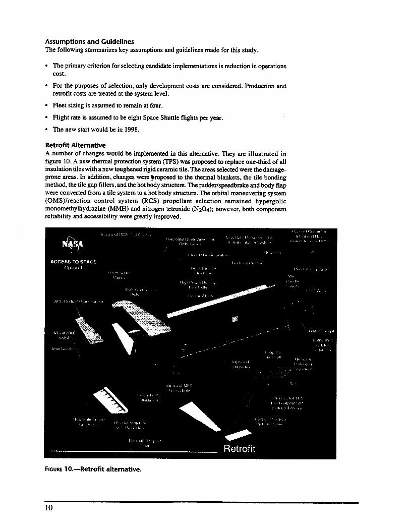
Retrofit Alternative
A number of changes would be implemented in this alternative. They are illustrated in
figure 10. A new thermal protection system (TPS) was proposed to replace one-third of all
insulation tiles with a new toughened rigid ceramic tile. The areas selected were the damage-prone areas. In addition, changes were _roposed to the thermal blankets, the tile bonding
method, the tile gap fillers, and the hot body structure. The rudder/speedbrake and body flap
were converted from a tile system to a hot body structure. The orbital maneuvering system
(OMS)/reaction control system (RCS) propellant selection remained hypergolicmonomethylhydrazine MH) and nitrogen tetroxide (N204); however, both component
reliability and accessibility were greatly improved.
FIGURElO.mRetrofit alternative.
10
The new avionics system includes a new integrated communication system, a new navigation
system based on the Global Positioning System (GPS and differential GPS), and a new data
management system. The new avionics system reduces the number of line replaceable units
(LRU's) in the forward avionics bays, resulting in elimination of avionics bays 3a and 3b. The
middeck lockers were relocated to where avionics bays 3a and 3b were, allowing improvedaccessibility into bays 1 and 2.
The new mechanical and electrical power system replaced the hydrazine auxiliary power
system with an electrical-based auxiliary power system powered by three dedicated high-density fuel cells. In addition, changes were made to the hybrid load controller assemblies,
the instrumentation power system, the fuel cells, and the electrical wire protection system.
The major changes to the Environmental Control and Life Support System (ECLSS) were the
addition of quick disconnects for easier access, elimination of the need for ground support
equipment (GSE) cooling post-landing, and an assortment of other minor changes.
Modifications to the orbiter structure focused on replacement of the boron/aluminum struts
on an attrition basis with more robust struts, the capability to inspect for corrosion on the
rudder/speedbrake, and elimination of the wing flipper door replacement accomplished by
modifications to the wing design.
Minor modifications were made to the orbiter's main propulsion system (MPS). The Space
Shuttle main engine (SSME) was baselined to use the year-2000 configuration engine whichincludes advanced technology fuel and oxidizer turbopumps, a large throat main combustion
chamber, a phase II powerhead and single coil heat exchanger, and block 1I controller
improvements. In addition, a new main engine controller would be brought on-line.
The higher performance super-lightweight tank (SLWT) design would be used for the
external tank (ET), along with an assortment of other modifications. The modifications to the
solid rocket boosters (SRB's) included replacing the hydrazine auxiliary power unit (APU)
with a solid propellant gas generator and utilizing laser-initiated pyrotechnics.
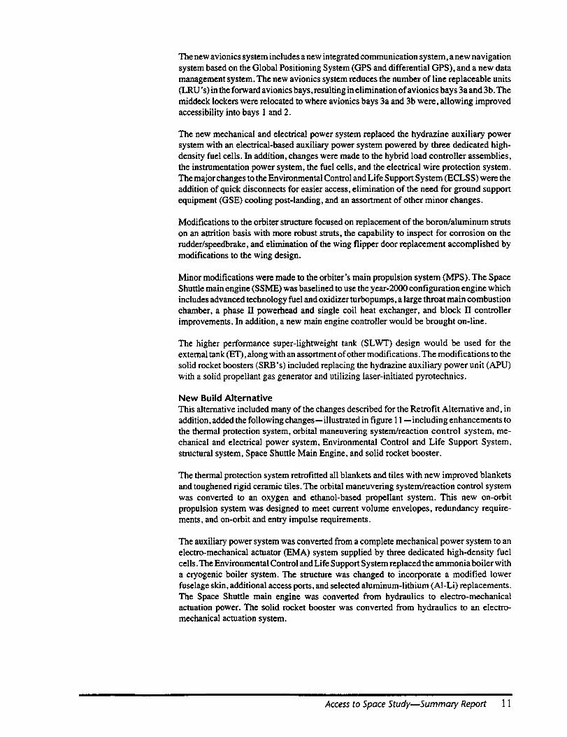
New Build Alternative
This alternative included many of the changes described for the Retrofit Alternative and, in
addition, added the following changes-- illustrated in figure 11 -- including enhancements to
the thermal protection system, orbital maneuvering system/reaction control system, me-
chanical and electrical power system, Environmental Control and Life Support System,
structural system, Space Shuttle Main Engine, and solid rocket booster.
The thermal protection system retrofitted all blankets and tiles with new improved blankets
and toughened rigid ceramic tiles. The orbital maneuvering system/reaction control system
was converted to an oxygen and ethanol-based propellant system. This new on-orbit
propulsion system was designed to meet current volume envelopes, redundancy require-
ments, and on-orbit and entry impulse requirements.
The auxiliary power system was converted from a complete mechanical power system to an
electro-mechanical actuator (EMA) system supplied by three dedicated high-density fuel
cells. The Environmental Control and Life Support System replaced the ammonia boiler with
a cryogenic boiler system. The structure was changed to incorporate a modified lower
fuselage skin, additional access ports, and selected aluminum-lithium (AI-Li) replacements.
The Space Shuttle main engine was converted from hydraulics to electro-mechanicalactuation power. The solid rocket booster was converted from hydraulics to an electro-
mechanical actuation system.
Access to Space Study--Summary Report 11
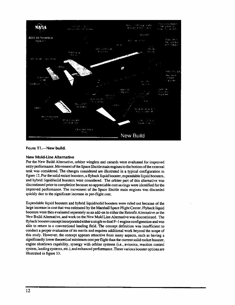
FIGURE1 1.reNew build.
New Mold-Line Alternative
For the New Build Alternative, orbiter winglets and canards were evaluated for improved
entry performance. Movement of theSpace Shuttle main engines to the bottom of theexternal
tank was considered. The changes considered are illustrated in a typical configuration in
figure 12. For the solid rocket boosters,a fiyback liquid booster, expendable liquid boosters,and hybrid liquid/solid boosters were considered. The orbiter part of this alternative was
discontinued prior to completion because no appreciable cost savings were identified for the
improved performance. The movement of the Space Shuttle main engines was discarded
quickly due to the significant increase in per-flight cost.
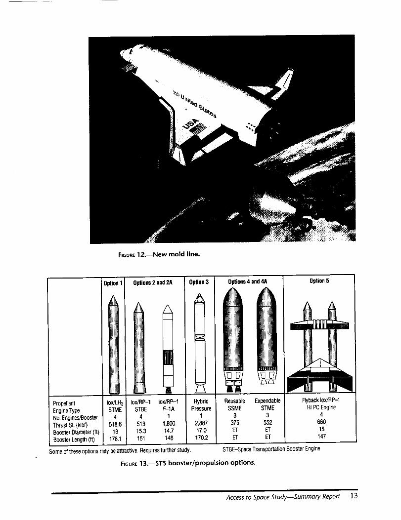
Expendable liquid boosters and hybrid liquid/solid boosters were ruled out because of the
large increase in cost that was estimated by the Marshall Space Flight Center. Flyback liquidboosters were then evaluated separately as an add-on to either the Retrofit Alternative or theNew Build Alternative, and work on the New Mold Line Alternative was discontinued. The
flyback booster concept incorporated either a single or dual F- 1engine configuration and was
able to return to a conventional landing field. The concept definition was insufficient to
conduct a proper evaluation of its merits and requires additional work beyond the scope of
this study. However, the concept appears attractive from many aspects, such as having asignificantly lower theoretical minimum cost per flight than the current solid rocket booster,
engine shutdown capability, synergy with orbiter systems (i.e., avionics, reaction control
system, landing systems, etc.), and enhanced performance. These various booster options areillustrated in figure 13.
12
FtGURE12.--New mold line.
0plions2 and2A
I
1[Propellant Iox/RP-1 Iox/RP-1EngineType STBE F-1A
No.Engines/Booster 4 1ThrustSL (klbf) 513 1,800BoosterDiameter(ft) 15.3 14.7BoosterLength(ft) 151 148
Someof theseoptions maybeattractive.Requiresfurther study.
Option3
m
m
Options4 and4A
HybridPressure
1
2,88717.0170.2
Reusable ExpendableSSME STME
3 3375 552ET ETET ET
Option5
FlybackIox/RP-1Hi PCEngine
466015147
STBE-SpaceTransportation BoosterEngine
FIGURE13.--STS booster/propulsion options.
Access to Space Study--Summary Report 13

Additional Means of Increasing Safety and Decreasing Cost
In addition to defining implementations for the above evolution alternatives, two additional
systems were evaluated as add-ons. They were an auxiliary crew escape system and an
uncrewed orbiter system. The approach for the crew escape system was to evaluate concepts
that would provide a backup system for returning the crew for the full ascent phase of the
mission. However, concepts that would work above 140,000 feet resulted in prohibitive
weight/performance penalties. Therefore the study quickly narrowed in on concepts which
would work below 140,000 feet. Three detailed concepts were defined. They were a five
person ejection seat system, an eight person ejection seat system with an extended flight
deck, and an eight person escape pod system. The mass penalties ranged from 1,746 pounds
for the five person option to 7,588 pounds for the pod. The center of gravity was moved
significantly forward in all three concepts, resulting in severe restrictions on payloadplacement. These alternatives are illustrated in figure 14.
FIGURE14.--Crew escape comparison.
An uncrewed orbiter system was also evaluated. The new avionics system proposed for allof these alternatives would have the increased capability to allow for automation of the ascent
and entry functions currently performed by the pilot and commander. The main intent of this
new system function was to augment current flights with uncrewed commercial and DOD
satellite launches. It was viewed that these missions do not require an on-orbit crew. The
Shuttle system could be utilized in this configuration (uncrewed) for general satellite
launches. An associated increase in flight rate could result in a significant reduction in per-flight launch cost.
The second important advantage of an uncrewed orbiter system would be as a test platformfor future Space Transportation System (STS) evolution or single-stage-to-orbit vehicle
technology. New systems could be evaluated during uncrewed missions and then bebaselined for use on crewed missions.
14

Theuncrewed concept defined by the study resulted in an increase of 10,000 pounds
performance and a shift of the center of gravity 26 inches back. This performance gained
would have to be balanced with payload location or "ballast." The orbiter was not dedicated
to either the uncrewed or crewed configuration and could be converted between either mode
in the normal processing flow.
Subsystem Improvement Descriptions
Thermal Protection SystemThe flight history of the Space Shuttle has conclusively demonstrated the operational
effectiveness of the existing orbiter thermal protection system. However, several design and
materials improvements have been identified that have the potential to significantly reduce
orbiter thermal protection system processing requirements and costs.
Tile damage from the normal flight environment, runway debris impacts, and raindrop
impingement can be reduced by utilizing a thicker, tougher densification coating known as
toughened unipiece fibrous insulation (TUFI). The TUFI is compatible with the currentLI-2200 and FRCI-12 tiles, as well as the advanced HTP and AETB tile substrates. The
TUFI, which is a highly porous coating, may simplify tile rewaterproofing operations by
enabling the direct absorption of a spray-on waterproofing agent through the coating to thetile substrate, an attractive alternative to the current procedure of individually injecting tileswith DMES.
An advanced organic blanket consisting of polybenzimidazole (PBI) felt has been proposed
as a replacement for felt reusable surface insulation (FRSI). The PBI has a reuse temperaturelimit of 900+ °F. Two advanced ceramic blanketsmtailorable advanced blanket insulation
(TABI) and composite flexible blanket insulation (CFBI)---have been proposed as replace-ments for AFRSI. The TABI is an integrally woven fabric, while CFBI consists of a
multilayer assembly of foils and fabrics sewn together into a blanket. Both TABI and CFBI
can be reused without replacement below temperature limits of approximately 2,000 OF.
Because tile removal is required in order to replace filler bars charred by high-temperature
gap flows, the elimination of filler bars through the use of full-footprint SIP should
significantly reduce thermal protection system maintenance time. In areas subject to high
temperature gap flows, reusable ceramic Ames gap fillers will be employed.
Thermal protection system technology development programs, involving both high-tem-
perature waterproofing agents and new rewaterproofing techniques, are currently under wayat the NASA Ames Research Center (ARC). The ARC is pursuing the development of a
"permanent" ceramic waterproofing agent with the goal of matching the reuse temperature
limit of ceramic tiles, approximately 2,700 °F.
Orbital Maneuvering System/Reaction Control SystemThe Retrofit Alternative retained the hypergolic based system, while the New Build
Alternative converted to a liquid oxygen (lox)/ethanol-based system.
For the Retrofit Alternative, the study concluded that it would be too difficult to convert the
current orbiter fleet to a new on-orbit propulsion system. Instead, the high maintenance rate
of the current system and inaccessibility of numerous components would be addressed. The
design changes selected were to redesign the primary thruster engine valves, helium quad
check valves, helium regulation system, quick disconnects, orbiter main engine (OME) ball
valve seals, and aft thruster feedline alignment bellows. The current pilot-operated valves on
the primary thruster would be replaced with new direct-acting valves. The seat design would
be similar to that of the vernier thrusters, which have a lower failure rate than the primary
thruster valves. The expected drop in failure rate would result in lower hardware maintenance
costs. Both the helium quad check valve and mechanical regulator components would be
replaced with an electronic regulator system installed with dynatube fittings.
Access to Space Study--Summary Report 15
The new electronic regulator system would be designed to be propellant insensitive and
capable of being fully checked out on orbit. When removal and replacement is required, thedynatube fittings would eliminate tube cuts that can result in small metal chips contaminating
the internal system. These metal chips are currently a major cause of excessive leakage rates
that are occurring on many orbital maneuvering system/reaction control system helium
components. The quick disconnects would be redesigned to be propellant insensitive. The
orbiter main engine ball valve seal would be replaced with one that does not leak. The aft
thruster feedline alignment bellows would be replaced with flexlines based on the forward
thruster design. In addition to the above redesigns, additional access doors would be added
to the pods.
The oxygen/ethanol propellant combination was selected because it eliminates the hyper-
golic servicing infrastructure, reduces the number of KSC-nnique fluids by one, fits withinthe current mold line, eliminates SCAPE suit operations, reduces or eliminates serial
processing required by the current orbital maneuvering system/reaction control system, and
eliminates a number of causes of orbital maneuvering system pod removal. In addition to the
above, the concept selected provides both the same redundancy level and total impulse level
that the current orbital maneuvering system/reaction control system provides. It is expected
that the operational cost for an oxygen/ethanol based on-orbit propulsion system will be
significantly lower than the current hypergolic-based system.
Avionics
Major changes were made to the communications and tracking system; the guidance,
navigation, and control system; and the data management and instrumentation system,
thereby reducing the number of line replaceable units. These changes led to the eliminationof avionics bays 3a and 3b. This enables the middeck lockers to be relocated to this location,
resulting in improved accessibility to avionics bays 1 and 2.
The current Communications and Tracking system was replaced with a more integrated
system. The new system resulted in fewer line replaceable units by combining the functionof the Communications Security (COMSEC) unit, the network signal processor (NSP), and
the transponder into a single line replaceable unit. A new payload computer would combinethe functions of the payload signal processor (PSP) and payload interrogator. The power amp
and preamp line replaceable unit to the antenna switch would be eliminated. The pulse-codemodulation master unit (PCMMU) and payload data interleaver (PDI) functions would be
incorporated into the new general purpose computers (NGPC) and payload computer.Increased data transmission rates would eliminate data downlist restrictions, resulting in a
single data format and deletion of the FM processor. A self-test capability would be
incorporated to provide fault isolation down to the line replaceable unit while installed on thevehicle and down to subassembly during bench-level testing.
The current navigation system would be completely changed to a new inertial navigation
system utilizing embedded GPS, embedded radar altimeter functions, differential GPS
capability, and IFOG gyros. A GPS antenna grid of six would be added to replace the startrackers. In addition to the star trackers, the inertial measurement unit (IMU)/high accuracy
inertial navigation system, tactical air navigation (TACAN), microwave scanning beam
landing system (MSBLS), accelerometer assemblies, and rate gyro assemblies would beeliminated.
The data management and instrumentation system would be upgraded to state-of-the-art
computers. The improved general purpose computers would incorporate fiber optic cables
for coupling to the multiplexer/demultiplexers (MDM's). Both the output/input recorders
and mass memory unit (MMU) would be changed to optical storage with the MMU installed
in the general purpose computer. The multifunction electronic display subsystem (MEDS)
that is currently under design would also be incorporated. The MDM's would be redesigned
to allow for individual cards to be replaced while still installed on the vehicle. The overall
16
avionics heat load would be reduced and would allow avionics to be totally cooled by air
purge only during all ground turnaround operations. A dedicated ground-located general
purpose computer (e.g., ground brain) would be capable of connecting directly into the
MDM's and either receive instrumentation data or command other subsystems without the
flight general purpose computers on-line. Finally, the backup flight software would beeliminated.
Orbiter Mechanical and Electrical Power Systems
Evolutionary improvements for the orbiter mechanical and electrical subsystems were
selected because of their ability to reduce operations cost and improve system safety in the
following areas.
• Hazardous ground operations associated with servicing the auxiliary power unit (APU)
hydrazine propellant and the high-pressure hydraulic systems.
• Ground operations associated with handling and disposing of toxic hydrazine propel-lants and hydraulic fluids.
• Flight safety issues associated with the hydrazine auxiliary power units and hydraulics.
• Excessive cycling of the orbiter systems to support ground checkout.
• Repair and replacement of fuel cells due to their limited life.
• Repair and replacement of electrical power distribution and control (EPDC) linereplaceable units.
• Repairing accidental damage to electrical wires which occur during ground operations.
An electric auxiliary power unit (EAPU), using high power density fuel cells (I-IPDFC) for
power, was determined to be the most cost-effective replacement for the hydrazine auxiliary
power units for the Retrofit Alternative. A modified water spray boiler (WSB) was used forcooling the HPDFC's. For a new-build orbiter, electro-mechanical actuators were selected
to replace the auxiliary power units and hydraulic system using high power density fuel cells
to supply electro-mechanical actuator electrical power.
The existing fuel cells would be replaced with the long life fuel cell with single-cell
instrumentation. The new fuel cells would have a lifetime five times longer than the current
fuel cells. The improved instrumentation and increased life would result in reduced line
replacable unit removal and replacement (R&R) costs and associated logistics costs.
Redesigned hybrid device controllers (HDC's) would be resettable and would reduce the
number of HDC removal and replacement occurrences. A redesigned load controllerassembly (LCA) would also be incorporated which would permit for HDC replacement
without load controller assembly removal from the orbiter.
The ability to provide power to selective components on the orbiter would be implemented
in both design alternatives to varying degrees. Both alternatives would incorporate a
dedicated instrumentation power bus and conditioning equipment for selected instrumenta-
tion, multiplexer/demultiplexers, and signal conditioners. The electro-mechanical actuators
for the new-build orbiter would be powered and controlled through ground support equip-
ment to facilitate ground processing. These improvements would significantly reduce the
amount of operating time on orbiter components, thereby increasing the mean time between
repair.
Finally, protective covers would be provided for orbiter wire bundles that are located in
frequently accessed areas and bundles would be rerouted for easier access. This modification
would reduce wire damage that occurs during ground operations.
Access to Space StudymSummary Report ] 7
Environmental Control and Life Support System
Quick disconnects would be installed on high-maintennnce components within the Freofl TM
and water (H20) coolant loops, allowing for removal and replacement without requiring a
complete deservice of the coolant system. In addition, built-in test (BIT) equipment would
be added for the radiator, ammonia, and flash evaporator system controllers, eliminating theneed for drag on ground support equipment in the Orbiter Processing Facility (OPF).
Midbody and aft cold plate thickness would be increased to reduce damage done to cold plates
during line replaceable unit removal and replacement.
The current waste compartment system (WCS) must be removed from the orbiter and shipped
to the Johnson Space Center for cleaning and refurbishment after each flight. The WCS
developed for the extended duration orbiter rEDO) would replace the existing WCS on all
vehicles. The new WCS uses a compactor/canister stowage concept, and does not need to be
removed from the orbiter for cleaning and refurbishment.
Relocating the H2 separator into the midbody area would eliminate vacuum vent inerting
ground support equipment and reduce launch countdown manual operations. Safety would
also be improved since there would be no H2 stored within the 2-inch overboard dump lineduring launch countdown.
The current PSA is designed as two separate pieces, and access to remove these units is
difficult. For all vehicles, the PSA would be redesigned for removal as a single unit, which
would allow easier removal and reinstaUation on the ground.
The new avionics being installed in all vehicles only require cold plate cooling. Therefore,avionics bay 1, 2, and 3 heat exchangers (HX's), six associated fans, and the inertial
measurement unit (IMU) heat exchanger and fan can be eliminated.
The ammonia boiler system would be replaced with a cryogenic boiler system on new-build
vehicles. This system would provide cooling at low altitudes, through landing and rollout.This system reduces the number of fluids required by the orbiter and eliminates hazardousoperations associated with ammonia.
It has been determined that purge air directed through the payload bay provides sufficient
cooling after landing. Therefore, the requirement for the 570-0508 cart at the runway can be
eliminated. Elimination of this requirement results in fewer operations at landing and areduction in maintenance of ground support equipment.
Currently, the extended memory unit (EMU) Personal Life Support System(PLSS) water
purity requirements are higher than what can be provided by the orbiter. The EMU PLSS
design will be changed to allow it to use the orbiter's water supply in its sublimator. This willeliminate 2 weeks of water polishing time at Kennedy Space Center after each extravehicular
activity (EVA).
Structural System
For new-build vehicles, aluminum-lithium (AI-Li) would be substituted for aluminum where
practical. This will result in a 3,900 pound weight savings over the current orbiter structural
mass, which would offset weight increases resulting from design enhancements in otherareas, as well as increase payload capability.
The current boron-aluminum (B-AI) midbody struts would be replaced with a more robust
material to reduce their susceptibility to damage by technicians working around them.
Currently, the midbody struts are being replaced with aluminum struts on an attrition basis.
For retrofit vehicles, this would continue until all struts are replaced, resulting in a net weightincrease of 200 pounds per orbiter. For a new-build vehicle, AI-Li will be substituted for the
B-A1 alloy, resulting in a net weight increase of about 180 pounds per orbiter.
18

The rudder speed brake (RSB) inner panels of the current orbiter fleet are susceptible to
corrosion and, therefore, require frequent inspection. Removal and subsequent reinstallation
of these panels to make repairs is difficult and time consuming. A design change to eliminate
this problem would be implemented on all vehicles, reducing inspection requirements,
material costs, analysis time, and precluding the need for reapplication of sealant.
The flipper door system is particularly difficult to service because of its complex design. Boththe retrofit and new build vehicles would replace the flipper door system with a wing
extension incorporating a piano hinge for wing access requirements. Incorporation of this
new design would reduce the maintenance time required to service the wing/elevon cavity,
as well as reduce weight.
For a new-build vehicle, the size of the current access ports to the aft compartment would be
increased to approximately four times their current size. This would enhance installation andremoval of ground support equipment, and allow more technician access at a given time.
Also, with less assembly of ground support equipment inside the aft compartment required,
accidental damage to components can be reduced. Access ports for other frequently serviced
areas will be built into new vehicles, as well, to reduce maintenance and inspection time.
For the retrofit vehicle, access ports will be added to the orbital maneuvering system pods,
providing easier access to the most frequently serviced internal components. This will allow
the orbital maneuvering system pods to remain on the vehicle for certain inspections andmaintenance.
Currently, hot spots seen on the orbiter mid-fuselage lower skin during reentry are handled
through the use of RTV heat sinks. For new-build vehicles, the design of the mid-fuselage
lower skin can be improved so that RTV heat sinks will not be required, resulting in a weight
reduction of 220 pounds.
One concept for crew escape is to provide ejection seats located on the flight deck. In orderto provide for this, the crew module would have to be extended 4.5 feet into the payload bay.
Main Propulsion System
Over 36 improvements to the main propulsion system were suggested by the members of theOption 1 team. Half of the implementations were selected by the both the Retrofit and New
Build Alternatives. The hardware improvements fell into two categories: improved system
operability and items that could be classified as preplanned program improvements.
Modifications to the main propulsion system include component changes, deletions, andadditions. Only the outboard LH2 and LO2 manifold fill and drain valve assemblies were
deleted. New components include leak check/purge ports between the GHe interconnect andthe check valves, instrumentation forLH2/LO2 fill/drain and LH2 recirculation system, purge
ports to facilitate orbiter GH2/GO2 system welding operations, protective covers for flexhoses, filters for the inlets/outlet of the LH2 and LO2 manifold relief pre-valves (6) and
inboard fill/drain relief valves, and fill/drain and pre-vaive inspection ports. Several compo-
nents would be redesigned including the helium check valves, LH2/LO2 relief valves, and the
K-seals on rough finished fittings. The foamed-in-place insulation on the engine interface
would be changed to precast insulation.
Operational changes would also be approved for the main propulsion system. These changesinclude provisions for orbiter flange lapping tools and certification of the SPC and/or NSLD
to perform required lapping in the field instead of having to return to the vendor, a centralized
new vacuum jacket readout panel and vacuum jacketed line repair techniques, extendedcertification on the external tank/orbiter umbilical joint line assemblies, particle induced
noise detection (PIND) testing on valve position switches, and extended certification on
limited life temperature probes.
Access to Space Study--Summary Report 19
Space Shuttle Main Engine
The only implementations selected for the Retrofit Alternative were the Vision 2000 SpaceShuttle main engine and a new main engine controller. The Vision 2000 Space Shuttle main
engine implementation, which has already been approved by the Space Shuttle Program,
consists of new Alternate Turbopump Development fuel and oxidizer pumps, a large throat
main combustion chamber (MCC), a phase ]I+ powerhead with a single cooling coil, and
block 11controller improvements. The Vision 2000 Space Shuttle main engine improvements
enable more complete servicing of the engines on the vehicle and allow the engines to remainon the vehicle for up to I0 flights. The new main engine controller implementation goes
beyond the changes made in the block II controller. The new main engine controller
incorporates the orbiter engine interface unit (EIU) function internally and allows the EIU to
be eliminated. The new controllers also provide increased capability for launching with failed
transducers by providing a more complex algorithm to determine which transducer is
providing a faulty reading and eliminating it from the voting scheme.
The New Build Alternative selected the retrofit implementations along with electro-
mechanical actuators for the Space Shuttle main engine thrust vector control fIN'C) systemand propellant valves. The Space Shuttle main engine's electro-mechanical actuators willwork in conjunction with the electro-mechanical actuators used for aerosurface control and
landing gear operations on the new-build vehicle. Complete elimination of the hydraulic
system on the orbiter is now possible. The Space Shuttle main engine's electro-mechanicalactuators would be powered by high-density fuel cells in the same manner as the other electro-mechanical actuators on the vehicle.
External Tank
Implementations for the external tank addressed increased performance and reductions in
manufacturing complexity. The first implementation selected was the super-lightweight
tank, which adds 8,000 to 12,000 pounds of Shuttle payload performance due to the lower
weight of the external tank. An assumption was made that the development of the super-lightweight tank would be implemented by the baseline program.
The manufacturing-related implementations selected include alternative thermal protection
system concepts and an electro-magnetic acoustic transducer (E T). The thermal protec-tion system alternatives address the use of composites and heat sinks instead of sprayed-on
foam. This reduces the labor involved with the thermal protection system application. The
EMAT is a new nondestructive technique for weld inspection. This new technique eliminates
today's labor intensive dye penetrant inspection. There are opportunities to use the techniquein other areas of orbiter processing as well.
Solid Rocket Booster
Solid rocket booster implementations focused on reducing the labor intensive operations
associated with processing the boosters. Alternative boosters were considered for replace-ment of the solid rocket boosters. Boosters considered were the advanced solid rocket motor
(ASRM), liquid rocket boosters (LRB 's) (LO2/RP-I), hybrids, and flyback LRB 's. The
flyback LRB was the only booster configuration that had a life cycle cost comparable with
the solid rocket boosters. Discussion of the flyback booster provided is given in theApproach, Ground Rules, and Organization section.
Improvements recommended for the solid rocket boosters included a solid propellant gasgenerator (SPGG) replacement for the hydrazine auxiliary power units, electro-mechanical
actuator replacement of the thrust vector control system along with an alternate power source
to replace the hydrazine auxiliary power units, and laser-initiated pyrotechnics. The solid
propellant gas generator and electro-mechanical actuator implementations are targeted to
eliminate the hydrazine auxiliary power units. Past studies have shown that an electro-
mechanical actuator thrust vector control system would net higher annual recurring savingsthan the SPGG, so this would be the preferred choice. The electro-mechanical actuator thrust
2O

vector control eliminates the hydraulics on the solid rocket boosters, as well: The laser-
initiated pyrotechnics eliminate elecromagnetic interference (EMI) concerns and enable
complete firing circuit verification after f'wing line connection. The ordnance connections can
be performed in the Vehicle Assembly Building (VAB) instead of late in the flow and do notrequire facility clears.
Ground and Flight Operations
Mass Properties and PerformanceThe mass properties and performance for the Retrofit and New Build Alternatives were
calculated by determining the incremental effects of each implementation chosen. A detailed
mass breakdown of Orbiter Vehicle (OV) 105 was used as a point of comparison for the
analysis.
Many of the hardware implementations selected require significant changes in the subsystem
definitions. Some changes overlap several subsystems. In some instances components are
removed, while other combinations add hardware. Most implementations modify the
existing components. The avionics implementations reduced the number of componentssignificantly, which reduced the system mass by over 900 pounds. However, other subsystem
implementations selected by the Retrofit Alternative offset the mass saving of the avionics
system.
The net effect for the Retrofit Alternative was to increase the vehicle mass by 58 pounds. The
center of gravity (CG) for the Retrofit Alternative was changed more significantly by the
implementations. The landed center of gravity is 5.2 inches aft of the landed center of gravityfor OV-105.
The New Build Alternative was permitted to change systems more extensively, including
structure. The New Build Alternative landed mass is 2,300 pounds lower than OV-105, butthe landed center of gravity remained unchanged.
The performance of the Retrofit Alternative is the same as for OV-105. Approximately
55,000 pounds can be transported to a 100 nautical mile, 28.5 degree orbit. When a super-lightweight tank is used, the lift capability is increased to approximately 63,000 pounds.
Performance to a 100 nautical mile orbit at an inclination of 51.6 degrees is approximately
49,000 pounds for the Retrofit Alternative.
The New Build Alternative performance is 2,300 pounds greater than OV- 105 or the RetrofitAlternative. The performance to an altitude of 100 nautical miles and an inclination of 28.5
degrees is approximately 57,000 pounds. The performance with a super-lightweight tank is
close to 65,000 pounds. The higher performance of the orbital maneuvering system on the
new-build vehicle offers more payload capability at higher altitudes than the OV-105 orRetrofit Alternative.
Technology PlanThe Space Shuttle evolution technology and advanced development plan for Option 1
addresses all flight-related subsystems and elements. The key technology and advanceddevelopment programs for Space Shuttle evolution are outlined below.
The development of high-temperature thermal protection system elements and/or nonhaz-
ardous thermal protection system waterproofing agents is critical to reducing thermal
protection system processing costs. Further characterization of TUFI coatings and AETB
and ACC tiles is required before implementation can be achieved. Advanced flexible
blankets, which will reduce operational costs through increased temperature margins, will
need further advanced development work as well.
Access to Space Study--Sumrnary Report 21
The development of propellant residue-insensitive valves will significantly reduce orbital
maneuvering system/reaction control system unscheduled maintenance operations and
costs. Accessing and developing low-toxicity propellants and propulsion systems, both
cryogenic and storable, will eliminate many of the hazardous propellant operations at theKennedy Space Center.
Advanced development and technology initiatives for avionics include the development offlight certified integrated guidance, navigation, and control (GN&C) units using interferom-
eter fiber optic gyro technologies, differential GPS for terminal approach, attitude determi-
nation using GPS for inertial navigation system (INS) alignment, digital signal processingcomponent development for communications and space flight-qualified high-definition
television components that are lightweight, small volume, and low power.
The data management system must develop stable software and hardware interfaces for
integration of commercially available off-the-shelf hardware that will mitigate long-term
obsolescence. Improved methods of software development and maintenance must be
developed using autocode generation, as well as improved software validation and verifica-tion methods.
Development of high-power density fuel cells and high voltage and high current switchingtechnology is required for both the electrical auxiliary power unit and electro-mechanical
actuator options. Advanced development of space qualified electro-mechanical actuators
and electrical hydrostatic actuators should be pursued.
A technology initiative that produces a Freon-21 replacement that is nonhazardous and
environmentally safe is very desirable. The development of cryogenic cooler/boiler andthermal wax pack heat rejection devices, which do not use toxic fluids such as ammonia,should be addressed.
A vehicle health management plan must be developed that focuses Agency technology
funding toward specific customer needs. Particular hardware development efforts shouldaddress built-in test capabilities for mechanical systems and line replacable unit fault
isolation, robust engine health instrumentation and algorithms, on-board leak isolation, smart
transducers and sensors, on-board solenoid valve current signature instrumentation, andhighly reliable valve position indicators.
Structural characterization of aluminum-lithium and high-temperature aluminums should bepursued.
Development of laser implementation of the NASA standard initiator, pyrotechnic initiator
controller, and safe and ann systems will reduce ground operations costs, improve system
safety, and reduce the number of anomalies associated with the current pyrotechnic systems.
Many of these technology developments are applicable to new launch vehicle systems aswell.
CostingAll cost data is reported in fiscal year (FY) 1994 dollars. Production costs for the solid rocket
booster, solid rocket motor, external tank, and Space Shuttle main engine are recurring costs
that are reflected in the baseline Space Shuttle Program budget. Wrap factors are in
accordance with NASA Comptroller instructions. The program support wrap was reduced to
five percent for design, development, test, and evaluation (DDT&E) and 0 percent forproduction. The NASA Cost Model (NASCOM) was used to estimate DDT&E and
production costs and the operations savings were estimated by grass-roots methods.
22
Recognizing the uncertainties of the study, the following conclusions were reached.
The cost savings identified to date in the Retrofit Alternative are $145M per year. The cost
to retrofit the fleet is estimated at $5.7B. Many of the individual changes identified in the
Retrofit Alternative should be implemented in any event; however, sufficient data does not
exist to recommend implementing the total package of proposed retrofit changes.
The cost savings identified to date in the New Build Alternative are $169M per year. The fleet
replacement cost is $15B. The New Build Alternative is not cost-effective, and there are nosubstantial reasons to build a new fleet. Features contained in the New Build Alternative
should be considered if and when a new orbiter is built.
Only the direct hardware-driven costs, about 32 percent of the Space Shuttle Program budget,
were addressed by the study. Current operations cost accounting methods were found to be
inadequate for accurately determining the savings from subsystem improvements. The
NASCOM was not designed for estimating modifications to existing systems, and there are
only limited tools available for estimating space flight operations costs.
Several recommendations were developed to improve the cost estimating capability. High
quality grass-roots estimates should be developed for high pay-back items. An activity-based
cost accounting system should be established to track all operations costs. New cost-
estimating relationships (CER's) should be developed to improve the estimating capabilityin selected areas. An effort should be initiated to develop an operations cost model and a new
NASCOM with factors for technical change, process improvements, and design inheritance.
FindingsThe Option 1 team found that the Retrofit Alternative was the best of the three alternativesexamined. It has the lowest investment cost and about the same savings in operations costs
as the others.
Providing additional crew escape capability was not recommended due to cost, weight, andcenter of gravity impacts, and technical risks. Several means to reduce costs further and
increase fight safety were identified. One is an uncrewed orbiter, which would allow the flight
rate to increase without impacting human safety, permit more flexible flight and payload
assignment, increase the payload capability of the Shuttle system for uncrewed cargodelivery. Another is to replace the solid rocket boosters with flyback liquid boosters, which
could increase safety and simultaneously improve operations efficiency.
The uncrewed orbiter has already had considerable definition, but the flyback booster
requires further study to define cost effectiveness.
The Shuttle system is safe and highly reliable, and could support the projected national
mission model through 2030. However, if the nation is to place primary reliance on the Space
Shuttle for this period, the current four orbiter fleet is not sufficient. Detailed plans must be
made for either orbiter replacement upon attrition or immediate expansion of the fleet size.
Many technologies have been identified that could prove useful to other concepts for future
space transportation. Associated technology development should be initiated soon. Exami-
nation of new ways of doing business to address non-hardware potential efficiencies should
proceed and be carried out by the Space Shuttle Program Office. Improvements to accountingmethods and cost data bases should also be undertaken.
Access to Space StudymSummary Report 23

Option 2 Team Analysis
Objectives and ApproachThe conventional technology options are requirements-driven architectures (with 1997
technology) that can replace the current launch systems in approximately 2005. These new
architectures are to meet the nation's total space transportation needs--civil, national
defense, and commercial --and to provide improved crew safety, acceptable life-cycle costs
(affordable design, development, test, and evaluation; improved operability and annual cost
reduction; and acceptable program risks), and a mission reliability of 0.98, and be environ-
mentally acceptable. The architectures should improve commercial competitiveness, con-tribute to the industrial economy, enable incremental development/improvements, and
provide improved capability relative to current systems.
The Option 2 approach was a multiphased process consisting of the spacecraft portion andthe launch vehicle portion. Mission options that dealt with crew and cargo logistics were
down-selected to three main architectural categories: (1) separate crew and cargo airframe,
(2) common crew and cargo airframe with HL--42 vehicle, and (3) common crew and cargo
airframe with CLV-P vehicle. Each mission option placed different requirements on thelaunch vehicle families.
The launch vehicle down-select process began with 84 vehicle families that were narrowedto 28, based on performance and propellant selection criteria. The 28 families were assessed
in a one-on-one comparison for each mission category based on cost, safety, environment,
risk, operability, and reliability. Four architectures were selected for detailed costing andwere defined and analyzed. They are illustrated in figure 15.
Alchltucture2A'
• 1.5 StageLVFamilyUtilizing
RecoverableP/AModule __
,lal
\/n
li! , ,|Delta Atlas STS/Td_n
Replacement
Features:
• Deltafor 1OkClass• Atlasfor 20k Class• STS/litanReplacementClass
- HL-42 for CrewTransport- ATVfor CargoTransport- SingleEngineCentaur- 1.5 StageParallelBum- All Iox/LH2- PartialReusable(P/A)- SSME
Amhituetum2B
• ParallelBum LV FamilyUtilizing
Iox/LH2CoreandLRB's
ci: |m H| B!
iiIDelta 20k STS/I'_an
Replacement
Features:
• Deltafor 1OkClass
• New20kto RepLaceAtlas• STS/TdanReplacementClass- FullStationLogisticsReturn- CLV-Pfor CrewandCargo- SingleEngineCentaur- 2 StageParallelBum- All Iox/U-12- ExpendableLV Elements- LowCost,STME
- Commonality:Boosters/Core_Ok
Ficu_ 15.--Option 2 architecture overview.
Azchitucture2C
• ParallelBumLV FamilyUtilizingHybridStrap-on Boosters
IDetta
2
\/-
-,|
!20k STS/T'r_an
Replacement
Features:,
• Deltafor 1OkClass
• New20kto ReplaceAtlas• STS/T'danReplacementClass- HL-42 for CrewTransport- ATVfor CargoTransport- SingleEngineCentaur- 2 StageParallelBurn- HybridBooster/
Iox/LH2Core- ExpendableLVElements- LowCost,STME
-Cornrnonality:Corew/20k
Architecture2D
• SeriesBumLV FamilyBasedonLowCostJl_owRisk
RD-180 RussianEngine9
'_ _/-
i
|i
n i! a
Delta 20k STS/T_an
Replacement
Features:
• Deltafor 1OkClass
• New20kto ReplaceAtlas• STS/T_anReplacementClass
- HL-42 for CrewTransport- ATVfor CargoTransport- SingleEngineCentaur- 2 StageSeriesBum
-Iox/RP (1), Iox/LH2(2)- ExpendableLV Elements- RD180/J2S
24
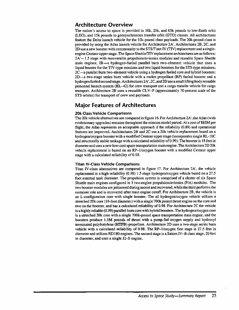
Architecture OverviewThe nation's access to space is provided in 10k, 20k, and 65k pounds to low-Earth orbit
(LEO), and 15k pounds to geosynchronous transfer orbit (GTO) classes. All architecturesfeature the Delta launch vehicle for the 10k-pound class payloads. The 20k-pound class is
provided by using the Atlas launch vehicle for Architecture 2A'. Architectures 2B, 2C, and
2D use a new booster with commonalty to the STS/Titan IV (TIV) replacement and a single-
engine Centaur upper stage. The Space Shuttle/TIV replacement architectures are as follows:
2A'-- 1.5 stage with recoverable propulsion/avionics modules and reusable Space Shuttle
main engines; 2B--a hydrogen-fueled parallel burn two-element vehicle that uses a
liquid booster for the TIV-type missions and two liquid boosters for the STS-type missions;2C--a parallel burn two-element vehicle using a hydrogen fueled core and hybrid boosters;
2D--a two-stage series burn vehicle with a rocket propellant (R.P) fueled booster and a
hydrogen fueled second stage. Architectures 2A', 2C,and 2D use a small lifting body reusable
personnel launch system (HL--42) for crew transport and a cargo transfer vehicle for cargotransport. Architecture 2B uses a reusable CLV-P (approximately 70-percent scale of the
STS orbiter) for transport of crew and payloads.
Major Features of Architectures
20k Class Vehicle ComparisonsThe 20k vehicle alternatives are compared in figure 16. For Architecture 2A', the Atlas (with
evolutionary upgrades) remains throughout the mission model period. At a cost of $85M per
flight, the Atlas represents an acceptable approach if the reliability (0.89) and operationalfeatures are improved. Architectures 2B and 2C use a 20k vehicle replacement based on a
hydrogen/oxygen booster with a modified Centaur upper stage (incorporates single RL- 10C
and structurally stable tankage with a calculated reliability of 0.99). The booster is 18 feet in
diameter and uses a new low-cost space transportation main engine. The Architecture 2D 20k
vehicle replacement is based on an RP-1/oxygen booster with a modified Centaur upper
stage with a calculated reliability of 0.98.
Titan IV-Class Vehicle Comparisons
Titan IV-class alternatives are compared in figure 17. For Architecture 2A', the vehicle
replacement is a high reliability (0.98) 1.5 stage hydrogen/oxygen vehicle based on a 27.5foot external tank diameter. The propulsion system is comprised of a cluster of six Space
Shuttle main engines configured in 3 two-engine propulsion/avionics (P/A) modules. The
two booster modules are jettisoned during ascent and recovered, while the third performs thesustainer role and is recovered after main engine cutoff. For Architecture 2B, the vehicle is
an L-configuration core with single booster. The all hydrogen/oxygen vehicle utilizes a
stretched 20k core (18-foot diameter) with a single 700k pound thrust engine on the core and
two on the booster, and has a calculated reliability of 0.98. For Architecture 2C the vehicle
is a highly reliable (0.99) parallel-burn core with hybrid boosters. The hydrogen/oxygen coreis a stretched 20k core with a single 700k-pound space transportation main engine, and the
boosters produce 1.5M pounds of thrust with a pump-fed oxygen supply and hydroxyl
terminated polybutylene (HTPB) propellant. Architecture 2D uses a two-stage series burn
vehicle with a calculated reliability of 0.98. The RP-1/oxygen first stage is 27.5 feet indiameter and utilizes RD 180 engines. The second stage is a Saturn IV-B class stage, 20 feet
in diameter, and uses a single J2-S engine.
Access to Space StudymSummary Report 25
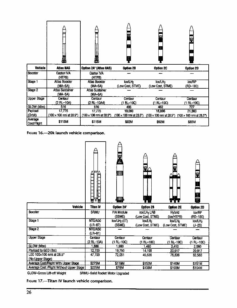
Vehicle
Booster
Stage1
Stage2
UpperS,age
GLOW(Idbs)Payload
(OrbS)Average
Cost/Right
Atlas IIAS
CastorIVA
(HTPB)AtlasBooster
(MA-SA)AtlasSustainer
(MA-5A)Centaur
(2 RL-10A)516
17,775
(100x 100nmiat28.5°)
$115M
!Option2A' (Atiu IIAS) Option2B Option2C Option2D
CastorIVA -- -- --
(HTPB)A1_asBooster Iox/LH2 Iox/LH2 ]ox/RP
(MA-5A) (LowCost,STME) (LowCost,STME) (RD--180)AtlasSustainer -- -- --
(MA-SA)Centaur Centaur Centaur Centaur
(2 RL-10A4) (1 RL-10C) (1 RL-10C) (1 RL-10C)516 495 462 727
17,775 19,060 18,896 21,660
(100x 100nmiat28.5") (100x 100nmiat28.5°) (100x 100nmiat28.5°) (100x 100nmiat28.5°)
$115M $92M $92M $85M
FIGURE16.--20k launch vehicle comparison.
Vehicle Titan IV Option2A' Option2B Option2C Option2D
Booster SRMU
Stage1
Stage2
UpperStage
GLOW(klbs)
PayloadtoGEO(ibs)LEO100x100 nmiat 28.5°
(No UpperStage)AverageCost/RightW_ UpperStage
AverageCost/Right W_houtUpperStagei
NTO/ASO
(LR-87)NTO/A50
(LR-91)Centaur
(2 RL-10A)1,88612,70047,700
GLOW-GrossUft-off Weight
$275M$225M
P/AModule Iox/LH2LRB Hybrid Iox/RP(SSME) (Low Cost,STME) (Iox/HTPB) (RD--180)
Iox/LH2(ET) Iox/LH2 Iox/LH2 Iox/]-H2
(SSME) (LowCost,STME) (LowCost,STME) (J-2S)
Centaur Centaur Centaur Centaur
(1RL-IOC) (IRL-IOC) (IRL-IOC) (IRL-IOC)1,980 1,480 2,410 2,06019,750 14,198 20,917 20,91772,051 45,636 76,836 83,583
$119M $152M $149M $151M$76M $108M $103M $104M
SRMU--SolidRocketMotorUpgraded
FIGURE17.--Titan IV launch vehicle comparison.
26
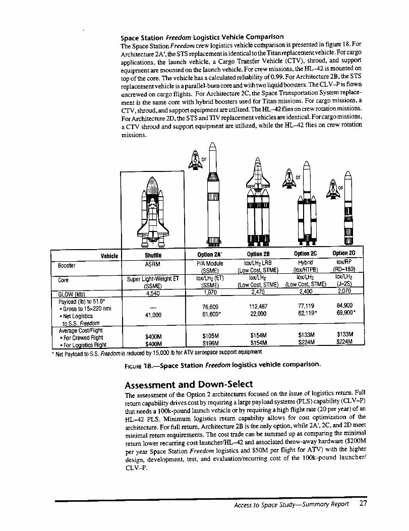
Space Station Freedom Logistics Vehicle ComparisonThe Space Station Freedom crew logistics vehicle comparison is presented in figure 18. For
Architecture 2A', the STS replacement is identical to the Titan replacement vehicle. For cargo
applications, the launch vehicle, a Cargo Transfer Vehicle (CTV), shroud, and supportequipment are mounted on the launch vehicle. For crew missions, the HL-42 is mounted on
top of the core. The vehicle has a calculated reliability of 0.99. For Architecture 2B, the STS
replacement vehicle is a parallel-bum core and with two liquid boosters. The CLV-P is flown
uncrewed on cargo flights. For Architecture 2C, the Space Transportation System replace-
ment is the same core with hybrid boosters used for Titan missions. For cargo missions, a
CTV, shroud, and support equipment are utilized. The HL-42 flies on crew rotation missions.
For Architecture 2D, the STS and TIV replacement vehicles are identical. For cargo missions,
a CTV shroud and support equipment are utilized, while the HL-42 flies on crew rotationmissions.
*rlf
Vehicle Shuttle Option2A' Option2B Option2C Option2D
8ooster ASRM
Core Super Light-WeightET(SSME)4,540
41,000
'GLOW(Idb)Payload(Ib) to 51.6°• Gross to 15x220 nmi
• NetLogisticsto S.S.Freedom
P/AModule Iox/LH2LRB Hybrid Iox/RP(SSME) (Low Cost,STME) (Iox/HTPB) (.RD-180)
Iox/LH2(ET) Iox/LH2 Iox/LH2 Iox/LH2(SSME) (Low Cost,STME) (Low Cost,STME) (J-2S)1,970 2,470 2,400 .2,070
76,609 112,487 77,119 84,90061,600" 22,000 62,119" 69,900*
AverageCost/Flight• ForCrewedFlight $400M $105M $154M $133M $133M* ForLogistics Flight $400M $196M $154M $224M $224M
NetPayloadto S.S.Freedomis reducedby 15,000 Ib for ATVaerospacesupportequipment
FIGURE18.--Space Station Freedom logistics vehicle comparison.
Assessment and Down-Select
The assessment of the Option 2 architectures focused on the issue of logistics return. Full
return capability drives cost by requiring a large payload systems (PLS) capability (CLV-P)that needs a 100k-pound launch vehicle or by requiring a high flight rate (20 per year) of an
HL-42 PLS. Minimum logistics return capability allows for cost optimization of the
architecture. For full return, Architecture 2B is the only option, while 2A', 2C, and 2D meet
minimal return requirements. The cost trade can be summed up as comparing the minimal
return lower recurring cost launcher/HL-42 and associated throw-away hardware ($200M
per year Space Station Freedom logistics and $50M per flight for ATV) with the higher
design, development, test, and evaluation/recurring cost of the 100k-pound launcher/CLV-P.
Access to Space StudymSummary Report 27

Space Station Logistics
Current plans call for over 200k pounds of Space Station Freedom logistics to be delivered
annually. The actual logistics mass, including sub-element packaging but excluding carriers
is approximately 150k pounds per year. However, the central issue relative to access to space
is the return mass. The current baseline, excluding logistics carriers, is 127k pounds. Analysis
conducted by Langley Research Center (LaRC) has shown that the baseline return might be
lowered from 127k pounds to 65k pounds by judicious return of spares, user, and crewsystems.
The 65k return requirement consists of the three categories (crew systems, users, and spares).
Each category was examined with LaRC and a return rationale was developed that empha-
sized the return of user payloads. All spares/maintenance were disposed along with five crewsystems racks. The full complement of nine EVA suits would be returned. The result is that
approximately 22k pounds of logistics would be returned. This would require three HL-42
flights per year for return mass. The acceptability of this level of return (approximately
15 percent of delivered mass) represents an issue that should be addressed in the final SpaceStation Freedom logistics scenario.
Space Station freedom Logistics Manifesting
A typical yearly Space Station Freedom manifest for Architecture 2D is shown in figure 19.
The eight flights deliver the required up-logistics and use the HL-42 for crew rotation and
selectecl logistics returns. Propulsion module (PM) propellant (7k pounds twice per year) is
delivered. Every five years, the full PM would be delivered (nine total flights) to replace lifelimited hardware. Modified logistics carriers---six-bay pressurized logistics module (PLM)
and 150-percent length unpressurized logistics carrier (ULC)--were needed to achieve this
yearly Space Station Freedom logistics support. Finally, this manifest returned the 78
middeck lockers, extravehicular activity suits, and approximately 65 percent of the userpressurized racks. The 2.8k pounds of user unpressurized logistics were not returned.
Architecture Elements
The separation of crew and cargo has been studied by NASA for the past several years. Theprimary focus was to minimize crew exposure by not flying a crewed vehicle, thus
eliminating crew system constraints for cargo-only missions. Personnel launch systems
(PLS) vehicles tended to be small vehicles having very limited cargo capability. Designs
varied from parachute recovery concepts (Biconic and Spacecab) to precision (runway)landers (HL-20 and HL-42). Cargo transfer and return (CTRV) vehicle designs ranged from
vehicles capable of cargo capacity similar to the orbiter (medium CTRV, winged CTRV/, andvertical lander) to smaller concepts (e.g., Spacecab, Caboose, integral CTRV). The CTRV
concepts included both vehicles recovered by parachutes (medium CTRV, Spacecab, and
Caboose) to precision lander (winged CTRV and vertical lander). Additionally, some design
concepts combined crew and cargo (crew logistics vehicle (CLV)) were also investigated.
The concepts were scaled versions of the current orbiter. Early in this study, it was recognizedthat precision landers were preferable for higher reliability and minimizing operations cost.
This down-selection of concepts eliminated all parachute landing and reduced the number of
PLS concepts from nine to three (HL-20, HL-42, and CLV) and CTRV concepts from 10 tothree (Winged CTRV, HL-42, and CLV).
Personnel Launch System
The down-selection process was derived from the Option 2 mission requirements and from
design issues that surfaced during the study. Precision lander (runway landing) concepts were
selected over parachute landing concepts to reduce the operations costs associated with
parachute landing concepts. Powered vertical landing vehicles were not selected, based on
risk. Smaller, less efficient crew/cargo vehicle concepts were eliminated in favor of the best
28
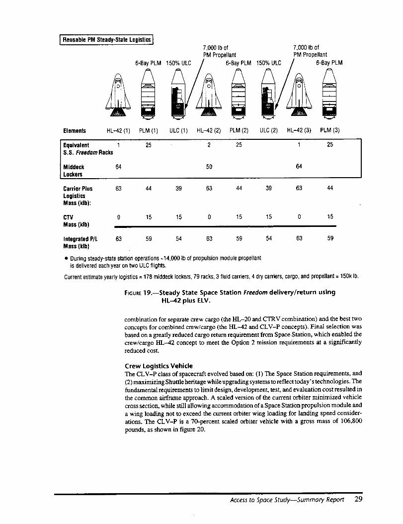
Reusable PM Steady-StaleLogisticsJ
6-Bay PLM
HL-42 (1)
7,000 Ib ofPM Propellant
1 6-Bay PLM
7,000 Ib ofPM Propellant
1 6-Bay PLM
Elements PLM (1) ULC(1) HL-42 (2) PLM (2) ULC(2) HL-42 (3) PLM (3)
Equivalent 1 25 2 25 1 25S.S. FreedomRacks
Middeck 64 50 64Lockers
Carrier Plus
LogisticsMass (klb):
63 44 39 63 44 39 63 44
CTV 0 15 15 0 15 15 0 15
Mass(klb)
Integrated P/L 63 59 54 63 59 54 63 59Mass (klb)
• During steady-state station operations-14,000 Ib of propulsion module propellantis deliveredeachyear ontwo ULCflights.
Current estimateyearlylogistics= 178 middeck lockers,79 racks,3 fluid carriers,4 dry carriers,cargo,and propellant= 150k lb.
FIGURE19.--Steady State Space Station Freedom delivery/return using
HL-42 plus ELM.
combination for separate crew cargo (the HL-20 and CTRV combination) and the best two
concepts for combined crew/cargo (the HL-42 and CLV-P concepts). Final selection was
based on a greatly reduced cargo return requirement from Space Station, which enabled the
crew/cargo HL-42 concept to meet the Option 2 mission requirements at a significantlyreduced cost.
Crew Logistics Vehicle
The CLV-P class of spacecraft evolved based on: (l) The Space Station requirements, and
(2) maximizing Shuttle heritage while upgrading systems to reflect today' s technologies. The
fundamental requirements to limit design, development, test, and evaluation cost resulted in
the common airframe approach. A scaled version of the current orbiter minimized vehicle
cross section, while still allowing accommodation of a Space Station propulsion module and
a wing loading not to exceed the current orbiter wing loading for landing speed consider-
ations. The CLV-P is a 70-percent scaled orbiter vehicle with a gross mass of 106,800
pounds, as shown in figure 20.
Access to Space Study--Summaty Report 29
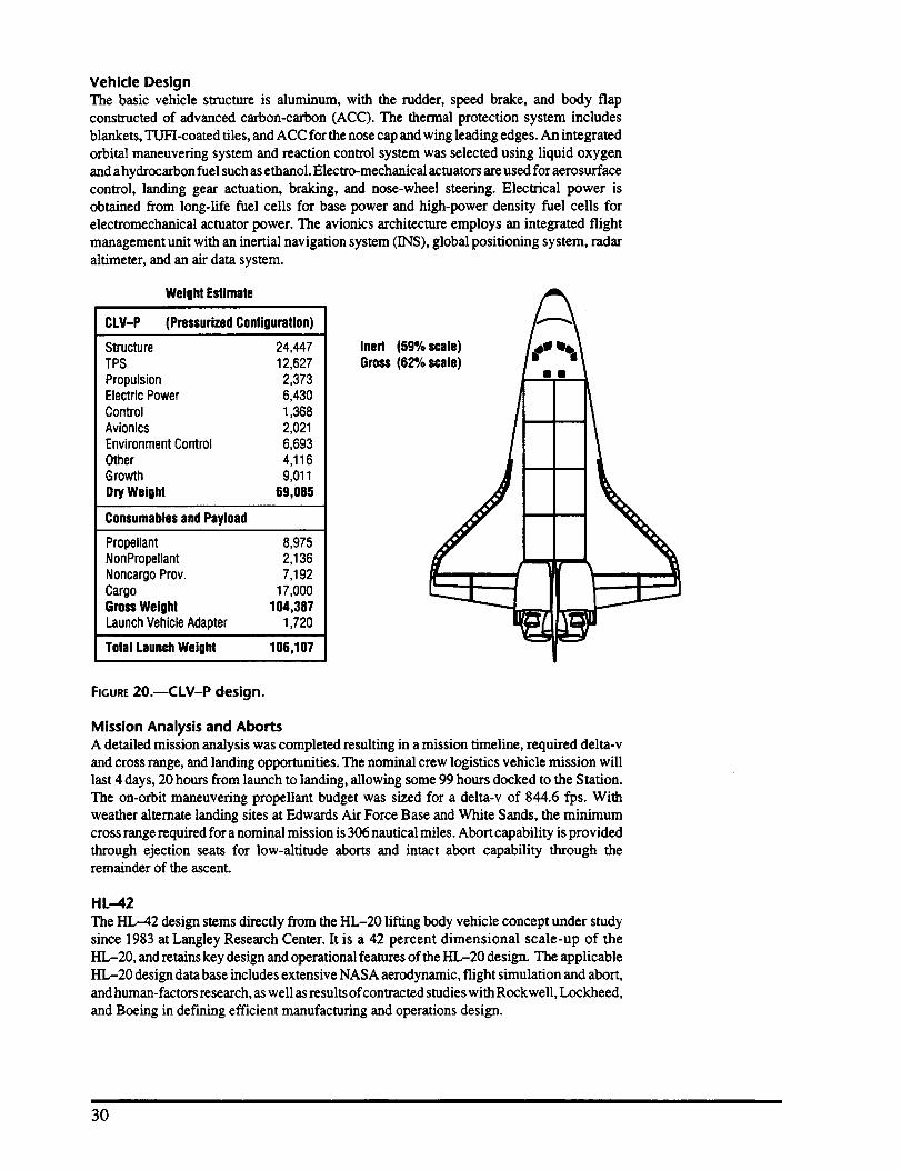
Vehicle DesignThe basic vehicle structure is aluminum, with the rudder, speed brake, and body flap
constructed of advanced carbon-carbon (ACC). The thermal protection system includes
blankets, TUFI-coated tiles, and ACC for the nose cap and wing leading edges. An integrated
orbital maneuvering system and reaction control system was selected using liquid oxygen
and a hydrocarbon fuel such as ethanol. Electro-mechanical actuators are used for aerosurface
control, landing gear actuation, braking, and nose-wheel steering. Electrical power is
obtained from long-life fuel cells for base power and high-power density fuel cells forelectromechanical actuator power. The avionics architecture employs an integrated flight
management unit with an inertial navigation system (INS), global positioning system, radar
altimeter, and an air data system.
WeigM Estimate
CLV-P (PressurizedConligumUon)
Structure 24,447TPS 12,627Propulsion 2,373ElectricPower 6,430Control 1,368Avionics 2,021EnvironmentControl 6,693Other 4,116Growth 9,011DryWeight 69,085
Consumablesand Payload
Propellant 8,975NonPropellant 2,136Noncargo Prov. 7,192Cargo 17,000GrossWeight 104,387LaunchVehicleAdapter 1,720
Total LaunchWeight 106,107
Inert (59% scale) I_!Gross (62% scale)
I
%\
FIGURE20.mCLV-P design.
Mission Analysis and Aborts
A detailed mission analysis was completed resulting in a mission timeline, required delta-v
and cross range, and landing opportunities. The nominal crew logistics vehicle mission will
last 4 days, 20 hours from launch to landing, allowing some 99 hours docked to the Station.The on-orbit maneuvering propellant budget was sized for a delta-v of 844.6 fps. With
weather alternate landing sites at Edwards Air Force Base and White Sands, the minimum
cross range required for a nominal mission is 306 nautical miles. Abort capability is provided
through ejection seats for low-altitude aborts and intact abort capability through theremainder of the ascent.
HL-42
The HL-42 design stems directly from the HL-20 lifting body vehicle concept under study
since 1983 at Langley Research Center. It is a 42 percent dimensional scale-up of the
HL-20, and retains key design and operational features of the HL-20 design. The applicable
HL-20 design data base includes extensive NASA aerodynamic, flight simulation and abort,
and human-factors research, as well as results of contracted studies with Rockwell, Lockheed,
and Boeing in defining efficient manufacturing and operations design.
30

Vehicle Design
The HL-42, shown in figure 21 is a reusable lifting-body spacecraft with launch escape
motors (for aborts) attached to the expendable launch vehicle adapter at the base of theHL,-42.
The core of the HL--42 design is an aluminum, cylindrical, pressurized cabin that contains
the crew and/or cargo. It has ingress/egress hatches at the top and rear of the cabin. Docking
at the Space Station occurs at the rear of the HI.,-42. A 53-inch Space Station hatch permits
loading and unloading of cargo as large as Space Station racks. Extending from thepressurized cabin are frame extensions that support the lower heat shield structure and define
subsystem bays. A multipiece titanium heat shield structure defines the underside of theHL-42,with the Thermal Protection System (TUH tiles) bonded directly to the titanium. The
upper surface is composed of aluminum honeycomb removable panels that define the
required aerodynamic shape and allow access to the subsystems located in the unpressurized
bay areas. AFRSI thermal protection system is bonded directly to these panels. The titaniumfins have direct bond thermal protection system (TUFI and FRSI) with the addition of
advanced carbon-carbon for the higher heating leading edges. The vehicle nosecap is alsomade of advanced carbon-carbon.
r--8-G LESMotors (4)
Span = 33.5 ft
42ft
f RTLSSustainerMotors (4)7' f AbortAdapter
2i in
X LBoosterAdapter
"- _ _ 128ft
Weight (Ib)
HL-42 Dry: 29,470Consumables: 7,748Crew/Payload: 9,300
On-0rbit: 46,518
AbortMotors: 10,870
Adapters: 5,961Total at Launch: 63,349
FIGURE21.--HL-42 design.
Flight control consists of seven moving surfaces--four body flaps, two elevons on the largefins, and an all-moving center vertical fin. Control movement is effected using electro-
mechanical actuators. Spacecraft power is supplied by hydrogen-oxygen fuel cells with
limited emergency power backup provided using rechargeable silver-zinc batteries. The
HL-42 propulsion consists of a methane (CH4) liquid oxygen orbital maneuvering system
and reaction control subsystem for multiaxis attitude control on orbit and during entry .The
CH4-liquid oxygen system was selected to delete hypergolic propellants and decreaseoperations cost.
Mission Analysis and Aborts
The HL-42 spacecraft is launched by an expendable booster into a 15 by 220 nautical mileinjection orbit inclined at 51.6 degrees. The orbital maneuvering system capability is 950 feet
per second, consistent with maneuvers required to transfer to a 220 nautical mile Space
Station orbit, circularization, rendezvous, and deorbit. Various combinations of crew and
cargo (Space Station racks, early/late access lockers, and extended memory unit suits) may
be carried by HL-42 in the pressurized cabin volume.
Access to Space Study--Sumrnary Report 31
Crew safety and intact recovery are two aspects of abort addressed by the HL-42 design. The
launch escape motors located on the launch vehicle adapter provide a high-thrust impulse torapidly distance the HL--42 from a catastrophic booster event. While the HL--42 is on the
launch pad and during the first 60 seconds of ascent, these abort motors provide for a return-
to-launch site (RTLS) capability and an intact runway landing. Some booster options also
provide additional return-to-launch site capability beyond this initial period. Also, limitedtransatlantic (TAL) and abort-to-orbit (ATO) options exist near the end of the ascent-
powered trajectory. However, for a significant portion of the ascent, with some architectures,
the abort mode may result in an ocean ditching using emergency parachutes on board the
HL--42. Under these conditions it is assumed the vehicle is expendable (not refurbished if
recovered). Based on the flight rate, this event is estimated to occur only once in the mission
model, with this vehicle attrition accounted for in the fleet sizing.
Cargo Transfer Vehicle
The nominal transfer vehicle reference mission is to provide uncrewed logistics resupply tothe Space Station and to destructively reenter with or without trash from the Station. The
transfer vehicle must also provide the capability to deliver replacement modules to the SpaceStation and to destructively reenter excess module hardware. A transfer vehicle function is
required in Option 2 architectures 2A', 2C, and 2D as the prime method of Space Station
logistics delivery as well as replacement module delivery. In Architecture 2B, the transfer
vehicle function is required only for module replacement/disposal.
Existing and future spacecraft(both foreign and domestic) with potential for use as transfer
vehicles were assessed. Three candidate systems met the mission requirements: U.S. Cargo
Transfer Vehicle (CTV from the National Launch System baseline design), EuropeanAutomated Transfer Vehicle (ATV), and the Russian Salyut Space Tug. Detailed informa-
tion was assembled for both the U.S. CTV and the ATV designs. Salyut Space Tuginformation was inadequate for this study.
Comparative analysis of the U.S. CTV and the ATV indicated that the systems were
essentially equal in performance and per-flight costs. However, the ATV design, develop-ment, test, and evaluation costs are the responsibility of the Europeans, whereas the U.S. CTV
design, development, test, and evaluation costs drive the peak funding requirements at thetime when requirements are the highest due to personnel launch systems and launch vehicle
development funding. In addition, the ATV provides an avenue for quidpro quo payment of
part or all of the European share of the Space Station operations costs. Thus, the ATV (figure
22) was judged to be the most cost-effective way to satisfy the transfer vehicle function
required by Option 2. Launch of the ATV from Kennedy Space Center using a U.S. launchvehicle was judged to be the most cost-effective way to use the ATV in all architectures for
Option 2.
Operations
Operations Ground Rules and Guidelines
Johnson Space Center, Kennedy Space Center, Langley Research Center, and Marshall
Space Flight Center jointly established ground rules and guidelines that are consistent with
an operationally efficient launch system and reduced operations costs. In order to minimize
ground operations costs, the following items were eliminated from design consideration:
solid rocket motors as core and booster stages; hydraulics; and hydrazine/N204 systems. An
integrated health management system was baselined to accomplish ground test and checkout
with minimum personnel time and in one to two shifts. All vehicle and payload elements
would be delivered to the launch site in flight-ready condition, with no open work. Test and
checkout procedures at the launch site that duplicate those operations accomplished at the
manufacturing facility have been eliminated. A crew chief approach is implemented at the
32

Dry WeightsbySubsystem
(kg) (Ib)
Propulsion 587 1,292GN&C 112 246DHS 68 150Communications 46 101
Power Supply 262 576Mechanisms 95 209ThermalControl 40 88Structure 516 1,136
ATVDry Mass 1,726 3.798
Margin(10%) 172 378
AI"VDry MassW/Margin 1,898 4,176
PropellantBudgets
Propellant Wet AW
ForCompositeATV/CargoMass (kg) (Ib) (kg) (Ib)
21 Metric Tons 2,983 6,563 4,881 10,738
25 Metric Tons 3,756 8,263 5,654 12,439
FIGURE22.--European Automated Transfer Vehicle.
launch site and the responsible launch site system/subsystem engineer provides the qualityassurance sign-off for the systems. After initial operating capability flOC), only"make-safe"
and "make-it-work" design changes would be implemented. A block upgrade philosophy
will be implemented to account for obsolescence and for cost reduction changes to the fleet.
Significant programmatic ground rules are: NASA operations support center exists only atmission control; ascent monitoring is accomplished at the launch site, with hand-over to
mission control at payload separation; after initial operating capability, all government
project/program support is at the launch site by one organization and the sustaining
engineering is at the launch site; there is one logistics system for all elements; and
configuration control is highly automated.
Significant portions of mission operations will be accomplished through the use of automatic
systems. Launch, ascent, on-orbit operations, entry, and landing are automated and require
no crew intervention, thus reducing cost by eliminating major requirements for facilities and
crew training. Payload interfaces and procedures, mission planning, mission manifesting and
premission products are simplified and standardized. Ground management of onboard
systems will be reduced by automation and onboard vehicle health management. Trajectoryand navigation management are decreased by using the Global Positioning Satellite system.
Ground Operations
All Option 2 vehicles will use the integrate/transfer/launch 0TL) method of processing. Thelaunch vehicle is vertically assembled and interfaces checked in the Vehicle Assembly
Building (VAB). Once assembled, all systems will be functionally checked by an onboard
autonomous test of the mechanical and fluid system, as well as electronic systems. Crewed
spacecraft are prepared for flight in one of the Orbiter Processing Facilities (OPF) and
transferred to the VAB for mating with the launch vehicle. Both LC39 pads will be modified
to conduct Option 2 launches.
Access to Space Study--Summary Report 33

Adoption of the "ready for flight" approach to launch operations for the boosters effectively
reduces the size of each option's launch crew; however, flight readiness testing and attendant
cost must be accounted for under manufacturing. The "ready for flight" requires delivery of
a "clean vehicle" with no open discrepancies or modifications. Additional staff reductions
were realized by applying commercial support to hands-on personnel ratios. Commercial
ratios are on the order of three-to-one compared to more than six-to-one for today's Shuttle.
As the number of people were reduced through lower support ratios and less testing, so were
the number of facilities necessary to house them.
Option 2 decreases the current number of facilities and requires no new facilities. Decreasingthe number of facilities carries with it a very significant cost reduction. Not only are facilities
reduced because of lower staffing levels and less testing, but they are further reduced by thefact that none of the families in the option use solid motors. Without solid motors, the entire
Vehicle Assembly Building can be used to house people and conduct parallel processing.Seven solid motor buildings and more than 70 trailers and boxcars would be closed.
The most logical launch site to modify for a 20k vehicle is Complex 40 and its Vertical
Integration Facility (VIF). Although no formal or informal agreement with the U.S. Air Force
exist for Option 2, this location is ideal since it is an integrate, transfer, and launch layout
similar to the Kennedy Space Center and meets Air Force requirements.
Mission OperationsThe proposed flight control and monitoring systems for the vehicles of the Option 2
architecture offer a unique opportunity to significantly change the current procedures for
conducting mission operations. These changes must be given serious consideration in order
to significantly reduce the operational life cycle cost of today's flight systems. It is believed
that the technology of the proposed systems will be available during the development phaseof the flight vehicles.
Primarily, it is the incorporation of internal vehicle health monitoring and control systems
and the Global Positioning System that gives the capability to revise current mission
operations procedures. Internal vehicle health monitoring and control systems axe practical
because of the technology advances in onboard computer systems. The Global PositioningSatellite is a proven system that provides instantaneous information on the position and
attitude of the vehicle. This information revolutionizes the navigation and guidance pro-
cesses for space vehicles. With the advent of these new technologies, the roles of flight crewsand controllers can be significantly reduced.
The Option 2 flight scenario assumes that the Kennedy Space Center will be responsible for
the flight of the expendable booster systems. Hight monitoring by the Johnson Space Center
occurs when the vehicle has separated from the booster system (generally occurs at orbital
insertion). Autonomous systems that had targeted the booster to the separation point would
transfer control to the orbital vehicle's autonomous system. This system would calculate the
orbital insertion and steer the vehicle to that position. The vehicle would than proceed to the
next pre-defmed phase of the mission. This sequence would continue until all the mission
events had been completed. Ground monitors will have the capability to terminate any phase
and re-initialize the autonomous flight system with new instructions.
The mission operations would require two facilities: a mission control center and a central
simulation facility. These facilities will be designed to support a minimum of 12 flights per
year. Design should provide for flight rate increase without major interference with current
operations. The mission control center would not be responsible for payload operations. Only
10 to 12 console monitoring and control positions would be required. No requirements for
real-time multipurpose support rooms have been identified. The mission control center
would not be used for dedicated training. All training would be conducted in the central
simulation facility. Training facilities should mirror flight control facilities for flight monitor
34

training.Thetrainingfacilitieswouldbeusedtoverifypre-flightanalyses.Theprimarymodeoftrainingwouldbecomputerbased.Nomotionbase,fixedbased,orflightaircraftfacilitieswillberequired.
Advanced Development Tasks RequiredThe selected technology/advanced development tasks that will enhance the next generation
space launch system include tasks applicable to all architectures and tasks unique to an
architecture. The generic tasks include: (1) avionics systems that can be upgraded, software
that is automatically generated and validated, and the health management of in-flight
functions; (2) electro-mechanical/hydraulic actuators and their electrical power driving andswitching systems must be matured, with emphasis on the power supply systems; (3)
advanced manufacturing to demonstrate and validate the most effective construction tech-
niques for the expended cryo-propellant tanks (automatic welding and statistical process
control (SPC) of components will reduce inspection, with significant reduction in cost and
facilities without compromising reliability); (4) nontoxic orbital maneuvering subsystem/
reaction control system propellant systems will increase the operational flexibility and
decrease the associated costs by elimination of hazardous systems and the associated control
of risks; and (5) a low-cost cryogenic upper stage engine, the number-one priority of the
Space Transportation Advisory Committee, is required for all architectures. Modification to
the existing Centaur and implementing an RL-10C engine, results in rapid development time
and low program risk. A single-engine Centaur decreases costs, increases reliability, andincreases operability. Application of advanced technology to the low-cost 50k-pound class
engine also increases the capability of architectures.
The architecture-unique technology tasks include reusable propulsion/avionics modules
(Architecture 2A') to substantially reduce launch costs. Propulsion/avionics modules pack-
age the costliest vehicle elements (main engines, auxiliary subsystem's power elements,main propulsion feedline elements, auxiliary propulsion subsystem, the thrust structure, and
vehicle flight avionics systems) to be recovered in a dry condition and with minimum
refurbishment. Hybrid motors (Architecture 2C) offer increased safety, low cost, operational
flexibility, and an environmentally "friendly" propulsion. The technology effort is to mature
and demonstrate hybrid propulsion technology to provide an adequate technology base andU.S. manufacturing infrastructure for U S. commercial expendable launch vehicle competi-
tiveness. A low-cost hydrogen fuel booster engine (Architectures 2B and 2C) using term-
advanced technologies will have low development costs, rapid development time, and low
program risk. The continuation of the space transportation main engine is required to retain
the capability to transition to Option 2 in 2002.
CostsDesign, development, test, and evaluation, production, and operations costs have been
estimated over the life of the program. All transportation costs that are required to launchNASA and Department of Defense payloads over the 1994 through 2030 time period have
been included, with the exceptions noted in the ground rules listed below. Although new and
innovative ways of doing business, compared to the traditional ways NASA programs have
been managed in the past, have been identified, their cost impact has not been fully qualified
or validated. The development of the HL-42 and the CLV-P could use a"Skunk Works" type
approach. This approach has been used successfully in major military programs such as the
Hercules, U-2, and SR-T1. In a study conducted on the HL-20 payload system by the
Langley Research Center and Lockheed, it was determined that significant savings could be
achieved using this approach. Based on those results, the new approach for the HL-42/
CLV-P could yield reductions as high as 40-45 percent in the total spacecraft development
and production cost estimates, compared to the traditional "business-as-usual" estimates.
I
Access to Space Study--Summary Report 35
These costing ground rules were followed:
• All costs are included with the following exceptions:
- Civil service salaries and travel, and research operations support (ROS)- Pre-plarmed product improvement after the year 2000- Commercial flights.
• Business as usual and new ways of doing business are included. The latter is characterizedby:
- "Skunk Works" development for HL-42 and CLV-P (ftrm requirements, single
management authority, small technical staff, customers on site, contractor inspec-
tions, limited outside access, timely funding, reports only important work, simpledrawing release, rapid prototyping, etc.).
• Launch services are purchased from commercial suppliers (eliminated program officePMS and ETB overheads, and reduced operations cost by 10 percent).
• Architectures 2A', 2C, and 2D assume reduced Space Station Freedom return cargo.Architecture 2B is full return.
• Costs assume use of single-engine Centaur for upper stage, Titan IV shroud, andEuropean Automated Transfer Vehicle.
• Cost estimates include reserves (30 percent of design, development, test, and evaluation,
20 percent of production), fee (10 percent), and program support (20 percem) except forproduction estimates based on actual current hardware production costs (i.e., externaltank modules, Centaur upper stage, shrouds, and Automated Transfer Vehicle).
• Expendable launch vehicle infrastructure cost adjustments are Department of Defense
estimates assuming 50 percent common, 25 percent Titan-unique, 12.5 percent Delta-unique and 12.5 percent Atlas-unique.
Unreliability costs for all vehicles except the Space Transportation System, are based on
actual experience on existing expendable launch vehicles and projected reliabilities fornew vehicles. Payload losses ($10k per pound) and reflight costs are included withHL-42 and CLV-P losses calculated for one vehicle each.
Launch vehicle design, development, test, and evaluation costs are spread over 4 yearsusing 60 percent cost/50 percent time Beta distribution. HL-42 and CLV-P are spreadover 6 years.
Production costs are spread over 3 years using 30 percent/40 percent/30 percent.
Pre-development costs of 7 percent design, development, test, and evaluation are
allocated at one percent for Phase A and six percent for Phase B.
The most cost-effective operations approach is for NASA to purchase commercial launch
services similar to the current Delta and Atlas. This enables a healthy competitive environ-
ment with foreign suppliers and places payloads in orbit at the lowest cost. This approach
would also reduce the government cost associated with project support, supporting the
program office, providing a support contractor base, and maintaining the NASA facilities
required to support the system over an extended operational period. Ten percent cost
reduction in ground processing and mission operations can be realized by the purchase oflaunch services.
Figure 23 shows the design, development, test, and evaluation and operations cost profile
over the 1994 to 2030 time period for Architectures 2A', 2B, 2C, and 2D. The cost estimates
include the total government resources required to meet the planned NASA and Department
of Defense mission models. The costs are plotted to show both the "business-as-usual"
(BAU) estimates and a "new ways of doing business" (NWDB) estimate. In the latter,
preliminary savings attributed to the "Skunk Works" type development and to the purchaseof launch services are identified.
36

lID
IP"tL
10
8
6
4
2
0
Architecture2A'10
LCC(NWODB)= $165BLCC(BAU) = $1768 8ii_!i_:, _ 6
___ _ ___ _ 4
i_ i:i:i:i:i:;_:_:' _:i_i i:_i : ._' "i_::.._I_I:_::.L_I,"._i:_: :. .,_::_:_:_: :::::
95 0 5 10 15 20 25 30
Architecture2B
LCC(NWODB)= $1758
i__& LCC(BAU)= $1938
i:_:i_,_i_. _:.._ _ ......,., ,............. ..........................
_i_:. _ _._ _ __:__ _.__:_ •_!__:_ :
95 0 5 10 15 20 25 30
10!
8
_ 4
2
Architecture2C10
LCC(NWOD8)= $1788
__l LCC(BAU)=$1948 _ 68
i_i_:_#_._i_ i_:_i_i_i_i_i_i_il_il _ 4
95 0 5 10 15 20 25 30
Architecture2D
LCC(NWODB)= $1768
__. LCC(BAU) = $192B_............_-.-
....=======================================........................._%:_:_:_:::.::.:,.......................|
95 0 5 10 15 20 25 30
[] DDT&E/Prod.W/HL-42 B Operations (Launch [] Delta DDT&E/Prod [] Delta OperationsSkunk Works Services) for BAU for BAU
BAU= Businessas usualNWODB= Newwaysof doing business
FIGURE23.--Total mission model cost spread.
Assessment
Option 2 satisfies all national launch needs including commercial, national security, and civil
missions. In addition, crew safety is improved by safe aborts for all mission phases, theelimination of solid rocket boosters, and reducing exposure from 8 to 3 flights per year. On
uncrewed flights, mission reliabilities of greater than 0.98 are achievable. The Option 2
architectures significantly reduce life-cycle costs. For modest investments of $7B-$13B,
annual operating costs can be reduced from $6.7B (current) to $3.7B-$4.0B, resulting in total
life-cycle cost savings of approximately $50B. The architectures reduce technical and
programmatic risk below prior programs by utilizing major elements/systems derived fromcurrent technology, large performance margins, evolution of existing propulsion systems,
and management practices that minimize requirements change/growth. Environmental
impacts are improved by the elimination of solids (except for small booster separation
motors) and the elimination of hypergols (except for single-engine Centaur roll control).
The Option 2 architectures enhance the commercial competitiveness of launch vehicles byutilizing launch vehicle services if the new ways of doing business are adopted and providing
competent capabilities in all payload ranges. Industrial capability is maintained and enhanced
through near-term development efforts that can be phased to allow steady capability
requirements (evolution path is 20k-cargo launch vehicle-crew transport launch vehicle). In
comparison to existing systems, Option 2 offers other distinct advantages such as perfor-
mance and reliability increases, operability increases, autonomous flight control, and growth
capability to meet next generation space missions.
Access to Space Study--Summary Report 37
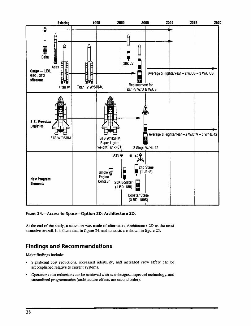
Existing 1995 2000 2005 2010 2015 2020
Cargo--LEO,GEO,GTOMissions
!. Im
i l " "
At s "
Titan IV
S.S. Freedom
Logistics
STSW/RSRM
New ProgramElements
:=_ 20k LV
v
|
[][]
[]
]l,
Average 5 Flights/Year - 2 W/US - 3 W/O US
!B!
Titan IV W/SRMU
STS W/RSRM
Super Light-weightTank (ET)
[]Replacementfor
Titan IV W/O & W/US
| Average 8 Flights/Year- 2 W/CTV- 3 WtHL 42[][]
2 StageW/HL 42
ATV_ HL--42_
2nd Stage
(1 J2-S)
Single !_
Engine_
Centaur _0K ;O_ i
BoosterStage(3 RD-180S)
I
FIGURE24.--Access to Space--Option 2D: Architecture 2D.
At the end of the study, a selection was made of alternative Architecture 2D as the most
attractive overall. It is illustrated in figure 24, and its costs are shown in figure 25.
Findings and Recommendations
Major findings include:
• Significant cost reductions, increased reliability, and increased crew safety can be
accomplished relative to current systems.
• Operations cost reductions can be achieved with new designs, improved technology, and
streamlined programmatics (architecture effects are second order).
38
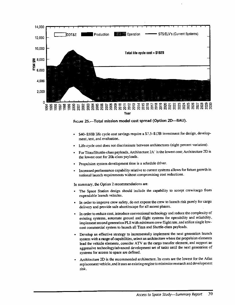
14,000
12,000
10,000
s= 8,000
>-
u. 6,000
4,000
2,000
0
|
I I I | I | I I I | I I I I I I I [ I I I 1 i | I I I I I I I I i i I /
['----'_DDT&E _ Production _ Operation _ STS/I-_'LV's(CurrentSystems)
Total life cyclecost= $192B
FIGURE25.--Total mission model cost spread (Option 2D---BAU).
• $40-$50B life cycle cost savings require a $7.5-$13B investment for design, develop-
ment, test, and evaluation.
• Life-cycle cost does not discriminate between architectures (eight percent variation).
• For Titan/Shuttle-class payloads, Architecture 2A' is the lowest cost; Architecture 2D isthe lowest cost for 20k-class payloads.
• Propulsion system development time is a schedule driver.
• Increased performance capability relative to current systems allows for future growth innational launch requirements without compromising cost reductions.
In summary, the Option 2 recommendations are:
• The Space Station design should include the capability to accept crew/cargo fromexpendable launch vehicles.
• In order to improve crew safety, do not expose the crew to launch risk purely for cargo
delivery and provide safe abort/escape for all ascent phases.
• In order to reduce cost, introduce conventional technology and reduce the complexity of
existing systems, automate ground and flight systems for operability and reliability,implement second generation PLS with minimum crew flight rate, and utilize single low-
cost commercial system to launch all Titan and Shuttle-class payloads.
• Develop an effective strategy to incrementally implement the next generation launch
system with a range of capabilities, select an architecture where the propulsion elements
lead the vehicle elements, consider ATV as the cargo transfer element, and support an
aggressive technology/advanced development set of tasks until the next generation ofsystems for access to space are defined.
• Architecture 2D is the recommended architecture. Its costs are the lowest for the Atlas
replacement vehicle, and it uses an existing engine to minimize research and developmentrisk.
Access to Space Study--Summary Report 39
Option 3 Team Analysis
ApproachA joint NASA and Department of Defense team was assembled to develop a well-rounded
approach to identifying the nation's space transportation architecture requirements and
implementation alternatives. Vehicle concepts were designed for robust operational margins,
instead of performance capability, through the use of various advanced technologies.
However, a "culture change" in launch vehicle development, certification, and operations
management must accompany the use of advanced technologies to leverage them to thegreatest extent possible. Relevant government and industry concepts, operations models, and
management philosophies were reviewed and considered by the team in its analysis.
Architectural Alternatives AnalyzedOn the basis of the 1990 Modified Civil Needs Data Base, approximately 90 percent of all
future low-Earth orbit payloads are under 20k pounds and are under 20 feet in length.
Delivery of these payloads (and their geosynchronous Earth orbit equivalent) was a primarydriver in determining the payload size requirement of the advanced technology vehicle.
There are approximately 18 satellite delivery missions in the 10k- to 20k-pound class each
year (low-Earth orbit equivalent). A new liquid oxygen (lox)fliquid hydrogen (I-I-I2) upper
stage, approximately one-third the size of the Centaur,will be required to transfer the largest
payloads from low-Earth orbit to geosynchronous-Earth orbit. The new vehicle is alsorequired to support satellite servicing missions at a rate of approximately one every 3 years.
An option for delivering Titan IV-class payloads was evaluated and vehicle concepts were
developed to deliver a 45k-pound payload to low-Earth orbit. However, this was not
baselined due to the small number of Titan-class flights per year (three), the uncertainty oftheir payload volume requirements post-2000, and because of the corresponding increase in
vehicle size. Instead, such a vehicle is treated as an option.
A total of 150k pounds of Space Station resupply logistics are required to be delivered, and
125k pounds to be returned, by the vehicle each year, based on current requirements for Space
Station permanently crewed capability. The Space Station payloads are transported using
standard unpressurized logistics carriers and the minipressurized logistics module.
Based upon previous flight experience and state-of-the-art avionics, the Option 3 vehicle
must be capable of autonomous flight operations. When required (e.g., servicing missions),
the vehicle has the capability of being operated on-orbit by a two-person crew to enhance
safety and perform nonstandard mission operations. Also, the vehicle must have thecapability to transport an additional four Space Station crew members and the associated
payloads that require late or early access.
Taking all domestic payload requirements into consideration, the advanced technology
vehicle is configured with a 25,000 pound payload capability to a 220 nautical mile circular
orbit inclined at 51.6 degrees. To meet this mission model, 39 flights per year, on average,
will be required. The vehicle has a payload bay that is 15 feet in diameter and 30-feet long.
An expendable launch vehicle of the Titan IV class will be used to meet the missions requiring
a 40,000 to 50,000 pound payload capability. However, an option has been developed that
uses a larger advanced technology vehicle to meet the all the requirements.
Space Transportation Architecture
Figure 26 illustrates the recommended Option 3 architecture based on the mission require-
ments from section 2.1. The 30- and 45-foot payload bay vehicles are shown as alternatives
A and B. Cargo and crewed missions are shown along with requirements for major new
elements and the approximate time frame of their implementation. This architecture is
generic, with the reusable launch vehicle icon shown in the figure representing several
advanced technology launch system concepts evaluated.
40
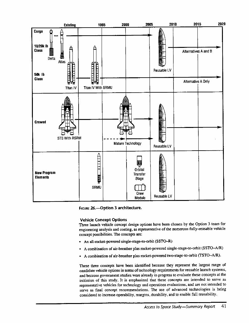
Existing 1995 2000 2005 2010 2015 2020
Cargo "z
10/20k Ib
Class {
Delta
50k IbClass
Atlas
m
I
ReusableLV
Crewed
Titan IV With SRMU
New ProgramElements
Titan IV
STSWith RSRM
SRMU
MatureTechnologyReusable LV
Orbital
Transfer
Stage _
CrewModule
Alternatives A and B
ReusableLV
AlternativeA Only
FIGURE26.--Option 3 architecture.
Vehicle Concept OptionsThree launch vehicle concept design options have been chosen by the Option 3 team for
engineering analysis and costing, as representative of the numerous fully-reusable vehicle
concept possibilities. The concepts are:
• An all-rocket-powered single-stage-to-orbit (SSTO--R)
• A combination of air-breather plus rocket-powered single-stage-to-orbit (SSTO-A/R)
• A combination of air-breather plus rocket-powered two-stage-to-orbit (TSTO--A/R).
These three concepts have been identified because they represent the largest range of
candidate vehicle options in terms of technology requirements for reusable launch systems,
and because government studies were already in progress to evaluate these concepts at the
initiation of this study. It is emphasized that these concepts are intended to serve as
representative vehicles for technology and operations evaluations, and are not intended toserve as final concept recommendations. The use of advanced technologies is being
considered to increase operability, margins, durability, and to enable full reusability.
Access to Space Study--Summary Report 41

Major Features of ArchitecturesThe three reference vehicle concepts were designed to an equivalent depth so that an "apples-
to-apples" comparison could be made. They all had features that would enhance reliability,operability, and maintainability. These features include the following:
• One-time vehicle flight certification.
- This requires building in increased margins over that used in the Space Shuttle design.
- The Space Shuttle is essentially recertified after each flight.
- The tests and inspections required for this greatly increase the ground processing time.
• Off-line payload processing.
- To minimize the impact of the payload on the vehicle, it is required that the payload be
processed separately from the vehicle and that the payload place minimum require-ments on the vehicle.
- The payload bay of the Space Shuttle is reconfignred for each flight, which againincreases the ground processing time.
• Minimize serial processing.
- To reduce the overall ground processing time, serial processes must be minimized.
• Durable thermal protection system.
- Many programs are underway, e.g., at Langley Research Center and Ames ResearchCenter, to develop a thermal protection system that is both more durable than the
current thermal protection system used by the Space Shuttle and also requires lessservicing between missions.
• Autonomous avionics.
- The use of the Global Positioning System, coupled with the advances in electronics,
makes this feasible using today's technology.
Table 1 compares the key features of each vehicle.
TABLE1 .--Reference vehicle comparisons
Feature SSTO(R) SSTO(A/n)
GrossMass(Ib) 1,961,303 917,000 352,000
DryMass(Ib) 159,500 239,000 252,000
Low-SpeedAirbreather/
EngineType RD-704 Ramjet/Scramjet Turbofans/Class & LinearModular Ramjets
AerospikeRocket
Lox Tank AI/Li Ai/LiIntegral/Circular Integral/Conformal N/A
LH2 Tank
SlushHydrogenTank
PrimaryStructure
TPS
AerosurfaceControls
Aerosurfaces
Integral/Circular
N/A
Gmph_eComposite
PassiveAFRSI/TABI/ACC
EMA
ACC
FuelCellsElectrical
PowerGeneration
N/A
GraphiteCompositeIntegral/Conformal
GraphiteComposite
PassiveFRCI-12/TABI/
Carbon-SiCActive
LH2
8000 psiaHydraulics
TMC(WithC/SICWhere
Needed)
FuelCells
TSTO(A/R) :(Booster) ,
I
TSTO(A/R)(Orbiter)
' 450,000!
' 52,000!!
!!, P&W RL-200' (NewEngineI
, Development)I!
o AI/U!, Non-Integral
GraphiteCompositeIntegral
N/A
GraphiteComposite
PassiveTABI/TUFI
!
, GraphiteComposite,' Integral°
' N/AI
!!, GraphiteComposite
!
!I, Passive' TABI/TUFI!!
!
!
8,000psia ,,Hydraulics ,
I
1"iWCI
I
II
AirTurbine ,I
I
EMA
ACC
FuelCells
42

Single-Stage-to-Orbit--All Rocket
The design philosophy of thereference single-stage-to-orbit all-rocket vehicle is to maximizethe lessons learned from the Space Shuttle program and apply the minimum technology
required to allow for an operationally efficient vehicle. These major design requirements, in
addition to the characteristics identified previously, include the following:
• Eliminate downrange abort sites
• Eliminate hydraulics
• Eliminate hypergolic propellants
• Use evolutionary engines
• Use AI-Li for the LH2 and lox tanks
• Use normal boiling point propellants
• Use simple circular cross-section fuselage and tanks
• Design propellant tanks for internal pressures similar to the Shuttle external tank.
The all-rocket-powered single-stage-to-orbit confignration is designed to take off vertically,like a standard launch vehicle, and land horizontally at mission completion, like the Space
Shuttle. Two suboptions exist within this rocket option: (I) a vehicle based on seven lox/LH2
engines evolved from the space shuttle main engine with equivalent performance character-
istics, but designed for higher levels of operability and maintainability; and (2) a vehicle
based on seven tripropellant (lox/RP/LH2) engines of the performance class of a single bellRussian RD-701 (i.e., RD-704). The RD-701 has component heritage from the RD--170
(Zenit and Energia booster engine) and RD-120 engines. The RD-701 drawings are 80
percent complete. This latter tripropellant option is illustrated in figure 27.
PayloadBay
GI I
',_ 150ft v,
Notes: • Vertical takeoff/horizontallanding• 15 percentdryweightmargin• Optionfor carryingtwo on-orbitoperations
crew for 7 days• Optionfor carrying four S.S.Freedomrotation
crewin payloadbay• Optionfor carrying highenergytransferstage
for Atlasclass(5k Ib) GEOmissions
Payload* Final Orbit25k Ib Station: 220 nmicircat 51.6"
*includes payload and ASE
Vehicle:GLOW:Dry Mass:Propellant Mass:PropellantType:Main EngineType/No.:
VacThrust(ea.) Mode1/2:VacISP Mode1/2:AreaRatio:
OMS EngineType/No.:VacThrust (ea.):VacIsp:AreaRatio:
CryoTanksPrimaryStructure:ControlSurfaces:TPS:
PayloadBay--Usable Volume
1.96 MIb159.5 klb1.74 MIb
Lox/LH2/RPRD-704/7
441.4/175.5 klb407/452
74:1
New Lox/LH26 klbf462 s100:1
AI-Li
Gr-CompositeACC
ACC/TABI/AFRSl15 ft Dx30ft L
FIGURE27.--Reference single-stage-to-orbit rocket.
Access to Space Study--Summary Report 43

In addition, after initial and preliminary discussions with the U.S. Air Force Space Com-
mand, it was determined that a 45-foot long cargo bay coupled with a 45k-pound payload
capability to low-Earth orbit at the 28.5 degree inclination may allow the advanced
technology vehicle to deliver the next generation of Titan IV payloads (scheduled to undergo
a block change early in the next century). Because of the requirement for a third propellant
tank (i.e., RP), the tripropellant option allows for a 15-foot diameter by 45-foot long cargo
bay to be placed longitudinally in the vehicle.
The masses associated with the lox hydrogen and the tripropellant vehicle variants are shown
in table 2, and the cost estimates in table 3.
TABLE2.--Vehicle masses
Dnj MassGrossMass
Lox/LH2
233k Ib2.48M Ib
Tripropellant: 30-fl Bay
159k Ib1.96M Ib
The weights of these vehicles can be reduced substantially by adopting graphite composites
for the fuel tanks instead of aluminum-lithium. This is discussed under the Single-Stage-to-
Orbit Feasibility section.
TABLE3.--Cost estimates for the single.stage-to-orbit rocket
FY94 $B Lox/LH2 Tripropellant:30-ft Bay
TechnologyDDT&EAnnualOperations*
0.9017.60
1.40
0.9016.701.40
* SSTOVehicleandAssociatedElementsOnly
Single-Stage-to-Orbit--Air-Breather/Rocket Combination
Air-breathing/rocket-powered, single-stage-to-orbit, horizontal takeoffand landing (HTOL)
aerospace planes are highly integrated systems with unprecedented levels of interdiscipli-
nary interactions involving a broad spectrum of technologies. This type of vehicle has
numerous design variables and can evolve to a robust, flexible machine using a highly
optimized design process if the systems/disciplines are integrated synergistically and theappropriate technologies matured. Such a vehicle can provide routine access to orbit at
reduced cost, increased operational flexibility (ground and flight), and reliability. Many of
these attributes stem from the airplane characteristics of this vehicle, such as lifting body, air-
breathing propulsion, horizontal takeoff and landing, and so forth. The single-stage-to-orbit
air-breather/rocket combination is an airplane that goes into orbit and, as such, can be
expected to accrue many of the desirable operational characteristics associated with contem-
porary high-performance aircraft. Specifically, they materialize through:
. Gradual step and check engine startup and shutdown
- Horizontal takeoff/abort capability
• Atmospheric abort with powered fly back
• Large launch window potential
• Launch offset capability
• Large cross range
• Subsonic and/or supersonic ferry capability with either SLH2 or LH2
• Hypersonic cruise capability.
44

Theair-breathing/rocket-poweredsingle-stage-to-orbitconfigurationisdesignedtotakeoffhorizontallyandlandhorizontally.ThebaselinepropulsionsystemisderivedfromthatbeingdevelopedbytheNationalAerospacePlane(NASP)Program.Thereferencevehicleusesaspeciallow-speedpropulsionmode,ramjets,andsupersoniccombustionramjets(scramjets)forprimarypropulsionalongwithlox/LH2rocketaugmentationinthelowandhighspeedregimesoftheascenttrajectory.Thereferencevehiclehasagrosslift-offmassofapproxi-mately900,000poundsandadrymassofapproximately240,000pounds.Thisconceptisillustratedinfigure28.
!_ 20O ftr
vPayload Bay
25 , C',ox_ Main Engine
.__ Machinery
Notes: • Horizontal takeoff/horizontal landing• 15 percent dry weightmargin• Option for carryingtwo on-orbitoperations
crewfor 7 days• Option for carrying four S.S. Freedomrotation
crew inpayloadbay• Option for carrying highenergytransfer
stagefor Atlas-classGE0 missions
Vehicle:
Payload* Final Orbit25k Ib Station: 220 nmi circat 516"52k Ib 100 nmicircat 28.5*32k Ib 220 nmicircat 28.5*14k Ib 100 nmi circat 90*
*includespayloadandASE
GLOW: 917k Ib
DryMass: 239k IbPropellantType: Lox/LH2Main EngineType: Air-breather/Rocket
Aux.EngineType/No.: IME Iox/LH2 pump fed/1Vac Thrust (ea): 300k IbVac ISP: 456 sArea Ratio: 150
CryoTanks: Gr-EpLH2/AI-Li IoxPrimary Structure: Gr-EpControl Surfaces: TMC/ACCTPS: FRCI-12/TABI
PayloadBay--Usable Volume: 15 ftx 15 ftx30 ft
FIGURE28.--Single-stage-to-orbit (air-breather/rocket)vehicle characteristics.
The cost estimates are given in table 4.
TABLE4.--Cost estimates for the single-stage-to-orbit air-breather�rocket
FY94$B
Technology 3.10
DDT&E 22.0
Annual Operations* 1.5
SSTOvehicleandassociatedelementsonly
Access to Space Study--Summary Report 45

Two-Stage-to-Orbit_Air-Breather/Rocket Combination
The air-breather/rocket-powered two-stage-to-orbit configuration is designed to take offhorizontally and land horizontally. The vehicle configuration consists of a booster vehicle
and a piggyback orbiter vehicle. The booster propulsion system is a combination of turbofan
jet engines and LH2 fueled ramjets. The booster/orbiter staging velocity occurs at Mach 5.
The orbiter is powered by four RI._200 class of rocket engines. The reference vehicle has a
combined gross liftoff mass of approximately 800,000 pounds and a dry mass of approxi-
mately 250,000 pounds. This concept is illustrated in figure 29.
Booster/OrbiterCombination
±
t*- 75tt-- l
Orbiter
Notes: • Horizontaltakeoff/horizontal landing• Orbiterstagedat M = 5• 15 percent dry weightmargin• Optionfor carryingtwo on-orbit operations
crew for 7 clays• Optionfor carrying four S.S. Freedomrotation
crew in payload bay• Optionfor carryinghighenergytransfer
stage for Atlas-classGEOmissions
Payload* Final Orbit25k Ib Station:220 nmicircat 51.6°32k Ib 100 nmicircat 28.5°31k Ib 220 nmicircat 28.5°24k Ib 100 nmicircat 90°*IncludespayloadandASE.
GLOW: 802k Ib
Booster-
DryMass:PropellantMass:PropellantType:EngineType/No.:
LH2 CryoTank:Primary Structure:ControlSurfaces:TPS:
252k Ib95k Ib
LH2Turbofan/Ramjet
Gr-EpGr-Ep
Ti H/CTABI
Orbiter:
DryMass:PropellantMass:PropellantType:MainRocketEngineType/No.:
T/W:Vac ISP:
CryoTanks:PrimaryStructure:ControlSurfaces:TPS:
PayloadBay-- UsableVolume:
52k Ib367k Ib
LOX/LH2ExpanderCycle/4
54446
Gr-EpLH2/AI-LiIoxGr-Ep
ACCTABI/'IUFI
15ft D ×30ft L
FIGURE29.mTwo-stage-to-orbit (air-breather/rocket) vehicle characteristics.
The cost estimates arc shown in table 5.
TABLE5.mCOSt estimates for the two-stage-to-orbit air-breather�rocket
FYe4se
Technology 1.20
DDT&E 26.80
AnnualOperations* 1.45
* SSTOvehicleandassociatedelementsonly
46
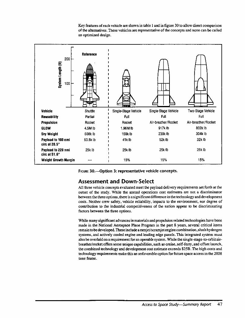
Key features of each vehicle are shown in table 1 and in figure 30 to allow direct comparison
of the alternatives. These vehicles are representative of the concepts and none can be called
an optimized design.
200
C0
E
"_ 100
Vehicle
Reusability
Propulsion
GLOW
Dry Weight
Payload to 100 nmicirc at 28.5 °
Payload to 220 nmicirc at 51.6 °
Weight GrowthMargin
Reference
Shuttle
Partial
Rocket
4.5M Ib
508k Ib
53.8k Ib
25k Ib
-I=-
nm
Single-StageVehicle Single-StageVehicle
Full Full
Rocket Air-breather/Rocket
1.96M Ib 917k Ib
159k Ib 239k Ib
41k Ib 52k Ib
/I
Two-StageVehicle
Full
Air-breather/Rocket
802klb
304k Ib
32klb
25klb 25klb 25klb
15% 15% 15%
FIGURE30.--Option 3: representative vehicle concepts.
Assessment and Down-SelectAll three vehicle concepts evaluated meet the payload delivery requirements set forth at theoutset of the study. While the annual operations cost estimates are not a discriminator
between the three options, there is a significant difference in the technology and development
costs. Neither crew safety, vehicle reliability, impacts to the environment, nor degree ofcontribution to the industrial competitiveness of the nation appear to be discriminating
factors between the three options.
While many significant advances in materials and propulsion related technologies have beenmade in the National Aerospace Plane Program in the past 8 years, several critical items
remain to be developed. These include a ramjet/scramjet engine combination, slush hydrogen
systems, and actively cooled engine and leading edge panels. This integrated system must
also be overlaid on a requirement for an operable system. While the single-stage-to-orbit air-
breather/rocket offers some unique capabilities, such as cruise, self-ferry, and offset launch,
the combined technology and development cost estimate exceeds $25B. The high costs and
technology requirements make this an unfavorable option for future space access in the 2008time frame.
Access to Space Study--Summary Report 47
The two-stage-to-orbit air-breathing rocket vehicle, while having many of the advantages of
the single-stage-to-orbit air-breathing rocket vehicle, does not require the development of a
scramiet and actively cooled panels. However, it does require the development of twodissimilar stages. While the two-stage-to-orbit air-breathing rocket has a lower technology
cost than the single-stage-to-orbit air-breathing rocket (i.e., $1.2B), the technology and
development cost estimate is $28B. The reduced technology requirements for the two-stage
concept do not appear to offset the high development costs of this concept.
Therefore, the development of a single-stage-to-orbit all-rocket vehicle appears to be the best
blend of near-term achievable technology and affordability for routine space access begin-
ning in the 2008 time frame. Its combined technology and development cost is the lowest of
the alternatives, projected at $17.6-$18 5B. It is an evolutionary, not revolutionary, path that
relies on technologies mostly evolved over the past 20 years in the aerospace industry.
However, it does require the maturation and demonstration of several key technologies. Thisis expected to require $900M over 5 years.
The initial single-stage-to-orbit all rocket reference concept, carried throughout the majority
of the study, was based on seven Space Shuttle main engine-evolved engines. However, the
use of a tripropellant engine (of the R1_704 class) provides for a significant reduction in
overall vehicle dry mass (e.g., reduced development cost), as illustrated in figures 27 and 30.
At the design reference point of 15 percent dry mass margin, the tripropellant vehicle drymass is 32 percent lighter than the lox/LH2 vehicle. Because of the requirement for a thirdpropellant tank (i.e., R.P), the tripropellant option also allows for a longitudinal, 15-foot
diameter by 45-foot long cargo bay to be placed in the vehicle to meet Titan IV payload
requirements. The addition of a third propellant (RP) does not appear to significantly affectthe cost of operating the single-stage-to-orbit vehicle.
Because of the reduction in vehicle dry mass that allows the vehicle dry weight growth margin
to be increased to 25-35 percent, reduced cost, and the potential for meeting Titan IV payload
requirements, it is recommended that future studies focus on the development of a single-
stage-to-orbit all-rocket vehicle based on a tripropellant engine of the RD-704 performanceclass.
Details of Selected Architecture
The propulsion system for the reference vehicle is based on the Russian tripropellantRD--704 engine.
The single-stage-to-orbit all-rocket vehicle is a vertical take-off, horizontal landing, wingedconcept with a circular cross-section fuselage for structural efficiency. The payload bay is
located between an aft LI-I2 tank and a forward lox tank. The normal boiling point LH2 and
lox propellants are contained in integral, reusable cryogenic tanks constructed of aluminum-
lithium material. An option exists to construct the fuel tanks of graphite-composite materials
for extra margin. The capability for carrying a crew on missions that require human presence
is provided by a crew module which is interehangable with the cargo module, but the vehicleremains totally automated. The vehicle employs wing tip fin controllers for directional
control. A standardized payload canister concept is used with common interfaces that allow
off-line processing of payloads and rapid payload integration.
All nonpressurized primary structural materials are graphite composite, drawing on current
airplane and rocket designs. The thermal protection system is composed of advanced carbon-
carbon materials for the control surfaces, nose cap, and wing leading edge. The remaining
areas of the wing and body are covered with advanced fully reusable surface insulation(AFRSI) where ascent/entry stagnation temperatures will be below 1200 °F, or TABI where
stagnation temperatures will be below 2,000 OF. Both AFRSI and TABI are blanket-type.
The main propulsion system for the single-stage-to-orbit all-rocket vehicle consists of seven
tripropellant engines based on the RD-704 engine concept. Specifically, this is a
48
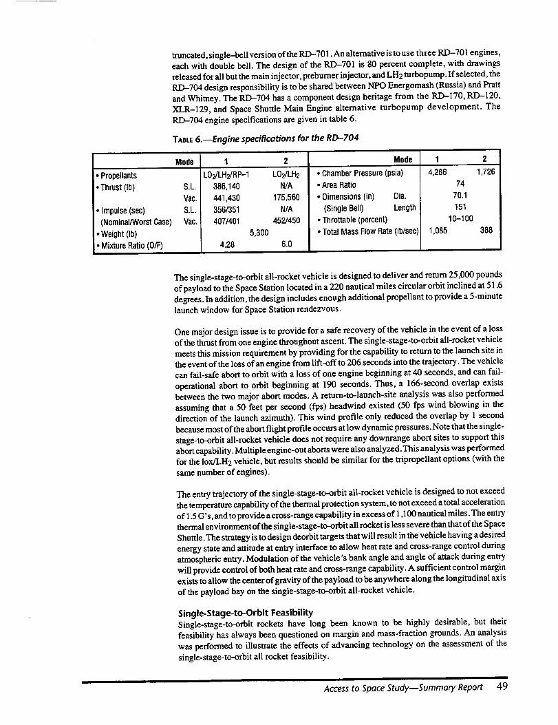
truncated, single-bell version of the RD--701. An alternative is to use three R.D-701 engines,
each with double bell. The design of the RD-701 is 80 percent complete, with drawings
released for all but the main injector, preburner injector, and LH2 turbopump. If selected, the
R.D-704 design responsibility is to be shared between NPO Energomash (Russia) and Pratt
and Whitney. The RD-71M has a component design heritage from the R.D-17O, RD-12O,XLR-129, and Space Shuttle Main Engine alternative turbopump development. The
RI_704 engine specifications are given in table 6.
TABLE6.--Engine specifications for the RD-704
• Propellants
• Thrust (Ib)
• Impulse (see)
(Nominal/WorstCase)
• Weight(Ib)
• MixtureRatio (O/F)
Mode 1 2 Mode 1 2
1,726
S.L
Vac.
S.L.
Vac.
LO2/LH2/RP-1 LO2/LH2
386,140 N/A
441,430 175,560
356/351 N/A
407/401 452/450
5,300
4.28 6.0
• Chamber Pressure (psia)
• Area Ratio
• Dimensions (in) Dia.
(Single Bell) Length
• Throttable(percent)I
• TotalMass FlowRate(Ib/sec)!
4,266
74
70.1
151
10-1 O0
1,085 388
The single-stage-to-orbit all-rocket vehicle is designed to deliver and return 25,000 pounds
of payload to the Space Station located in a 220 nautical miles circular orbit inclined at 51.6degrees. In addition, the design includes enough additional propellant to provide a 5-minute
launch window for Space Station rendezvous.
One major design issue is to provide for a safe recovery of the vehicle in the event of a loss
of the thrust from one engine throughout ascent. The single-stage-to-orbit all-rocket vehicle
meets this mission requirement by providing for the capability to return to the launch site in
the event of the loss of an engine from lift-off to 206 seconds into the trajectory. The vehiclecan fail-safe abort to orbit with a loss of one engine beginning at 40 seconds, and can fail-
operational abort to orbit beginning at 190 seconds. Thus, a 166-second overlap exists
between the two major abort modes. A return-to-launch-site analysis was also performed
assuming that a 50 feet per second (fps) headwind existed (50 fps wind blowing in the
direction of the launch azimuth). This wind profile only reduced the overlap by 1 second
because most of the abort flight profile occurs at low dynamic pressures. Note that the single-stage-to-orbit all-rocket vehicle does not require any downrange abort sites to support this
abort capability. Multiple engine-out aborts were also analyzed. This analysis was performed
for the lox/LH2 vehicle, but results should be similar for the tripropellant options (with the
same number of engines).
The entry trajectory of the single-stage-to-orbit all-rocket vehicle is designed to not exceed
the temperature capability of the thermal protection system, to not exceed a total accelerationof 1.5 G's, and to provide a cross-range capability in excess of 1,100 nautical miles. The entry
thermal environment of the single-stage-to-orbit all rocket is less severe than that of the Space
Shuttle. The strategy is to design deorbit targets that will result in the vehicle having a desired
energy state and attitude at entry interface to allow beat rate and cross-range control during
atmospheric entry. Modulation of the vehicle's bank angle and angle of attack during entry
will provide control of both heat rate and cross-range capability. A sufficient control margin
exists to allow the center of gravity of the payload to be anywhere along the longitudinal axisof the payload bay on the single-stage-to-orbit all-rocket vehicle.
Single-Stage-to-Orbit Feasibility
Single-stage-to-orbit rockets have long been known to be highly desirable, but their
feasibility has always been questioned on margin and mass-fraction grounds. An analysis
was performed to illustrate the effects of advancing technology on the assessment of the
single-stage-to-orbit all rocket feasibility.
Access to Space Study--Summary Report 49
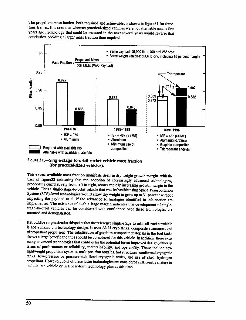
The propellant mass faction, both required and achievable, is shown in figure31 for three
time frames. It is seen that whereas practical-sized vehicles were not attainable until a few
years ago, technology that could be matured in the next several years would reverse thatconclusion, yielding a larger mass fraction than required.
1.00
0.95
CO
==.=u_
= 0.90a
E
0.85
0.80
• Same payload:45,000 Ibto 100 nmi 28• orbit• Sameweightvehicles:300k Ib dry, including15 percentmargin
PropellantMass
MassFraction=:rotal Mass 0N/O Payload)
0.838
0.92+
10.8830.872 _0.872
0.848
Pro-STS , 1975-1985
• ISP = 375 • laP = 437 (SSME)• Aluminum • Aluminum
• Minimumuseof
RequiredwithavailableIsp compositesAttainablewith availablematerials
Now--1995
• ISP= 437 (SSME)• Aluminum-Lithium
• Graphitecomposites• Tripropellantengines
FIGURE31 .--Single-stage-to-orbit rocket vehicle mass fraction
(for practical-sized vehicles).
This excess available mass fraction manifests itself in dry weight growth margin, with the
bars of figure32 indicating that the adoption of increasingly advanced technologies,
proceeding cumulatively from left to right, shows rapidly increasing growth margin in thevehicle. Thus a single-stage-to-orbit vehicle that was infeasible using Space Transportation
System (STS)-level technologies would allow dry weight to grow up to 31 percent without
impacting the payload at all if the advanced technologies identified in this section are
implemented. The existence of such a large margin indicates that development of single-
stage-to-orbit vehicles can be considered with confidence once these technologies arematured and demonstrated.
It should be emphasized at this point that the reference single-stage-to-orbit all-rocket vehicle
is not a maximum technology design. It uses A1-Li cryo tanks, composite structures, and
tripropellant propulsion. The substitution of graphite-composite materials in the fuel tanks
shows a large benefit and thus should be considered for this vehicle. In addition, there exist
many advanced technologies that could offer the potential for an improved design, either in
terms of performance or reliability, maintainability, and operability. These include new
lightweight propulsion systems, multiposition nozzles, hot structures, conformal cryogenic
tanks, low-pressure or pressure-stabilized cryogenic tanks, and use of slush hydrogen
propellant. However, none of these latter technologies are considered sufficiently mature toinclude in a vehicle or in a near-term technology plan at this time.
5O

A +50
= +40
m
5:.IZ
"_ +30.0
lul
"_ +203E"
_o--= +10¢D
-10
• Payload= 45,000 Ibinto 100 nmi 28° orbit
• Vehicledry weightconstantat 233k Ib Limit of 1993
TechnologyPlan
+31%
+21%
+15%
+2.5%Notachievablewiththesetechnologies
UseSTS Advanced Advanced Aluminum- Composite CompositeTripropellantTechnologySubsystems TPS Lithium Structures Hydrogen Propulsion
Only Tanks Tank
Cumulative Incorporationof AdvancedTechnologies
FIGURE32.--Weight growth margin available.
+4O%
Lightweight HotEngines Structures,
TI-AI-MMC,ConformalTanks,etc.
Operations PlanThree fundamental approaches are evident in every modem aerospace endeavor, and all are
equally important for a truly efficient launch capability:
• Design-in modem technology that can deliver a simpler vehicle- Design-out complex, less operable elements and subsystems (stages, hypergolics,
ground support equipment, etc.)- Design-in operability (subsystem access, vehicle health monitoring (VHM), etc.).
• Eliminate flight-by-flight vehicle detailed inspection (almost a certification)
- Proper margins proven in prototype testing- Confidence in subsystem status via vehicle health monitoring
- Perform major overhauls and inspections in regularly scheduled depot maintenance
periods (maintenance only by exception between flights).
• Manage for operations- Empower individuals to conduct full flight operations (program manager, crew chief,
and flight manager)-Separate development from operations (3:1 staffing ratio, reduced sustaining
engineering).
These philosophies and technologies will lead to a launch capability with fewer facilities, far
fewer people, fewer unique tools, and much lower costs. A program that capitalizes on thesebenchmarks can dramatically reduce the infrastructure and, therefore, the costs associated
with space launch. Under these philosophies, analyses of ground processing and flight
operations have shown a reduction in the complexity of operations, facilities, and staffing
required to conduct space launches. Operability is designed in from the start of the program.
Access to Space Study--Summary Report 51
Ground Operations
Analysis indicates that using these operations philosophies, the single-stage-to-orbit all-
rocket vehicle can deliver space launch capabilities with dramatically reduced operationscosts. The single-stage-to-orbit all-rocket vehicle has eliminated Space Shuttle vehicle
elements and associated Kennedy Space Center facilities and specialized support equipment.
Well-established flight margins and a comprehensive vehicle health monitoring system willprovide reduced pre- and post-flight testing requirements. These changes will reduce the
dedicated Kennedy Space Center workforce requirements by 1,100 people. Coupled with areduction in personnel support overhead (nontouch-to-touch labor ratio), reductions inKennedy Space Center ground processing costs of up to 55 percent can be realized. Launchcomplex 39A or B will be modified to allow for single-stage-to-orbit launch. The vehicle will
be processed in a hangar in the horizontal position, moved to the launch pad via a transporter,and erected to the vertical orientation.
Additionally, significant cost savings at non-KSC facilities are realized by the elimination of
Space Shuttle elements: continuing production and shipment of the external tank, productionand refurbishment of solid rocket motors, Spacelab, pre-planned product improvement, andother orbiter items (i.e., remote manipulator system). Elimination of these elements will
reduce the dedicated workforce requirements by an additional 8,800 people.
Mission Design and Operations
Similar to ground operations, the costs of mission design and operations can shrink
substantially by the incorporation of modern operations technology and philosophies.
The concept of a crew chief will be applied to the mission design and flight operationsactivities. A team of engineers led by a mission manager will be assigned to each vehicle and
given the responsibility for the mission design, definition of mission-unique software
parameters, and real-time mission support. Each team will consist of 20-25 engineers witha support team to maintain the operations support center, software verification laboratory,
and the required analysis tools and data bases. When necessary, additional systems supportwill be provided by the vehicle crew chief and ground team or depot maintenance team.
Given the autonomous operations for such areas as vehicle health monitoring, navigation,and targeting, and the use of automatic flight control systems built into the vehicle, themission design and flight operations functions can be handled with a significantly reducednumber of people from the number required by current Shuttle or expendable launch vehicleoperations.
Summary of Development StrategyBased on focused government and industry surveys, the team has identified a set of desirable
program attributes in the areas of management, technology maturation and development,production, operations, and maintenance. These include:
• Goals/objectives established at program start
• Quality and safety as top project priorities
• Strong customer involvement
• Streamlined budgeting/tailored acquisition procedures
• Single program manager with a small, centralized staff
• Small teams of expert staff
• Abbreviated reporting, coordinating, and review
• Limited interface specifications
• Utilize best commercial practices and standards
• Dedicated collocated design and development personnel
• Concurrent engineering
• Prototype approach to vehicle development.
52
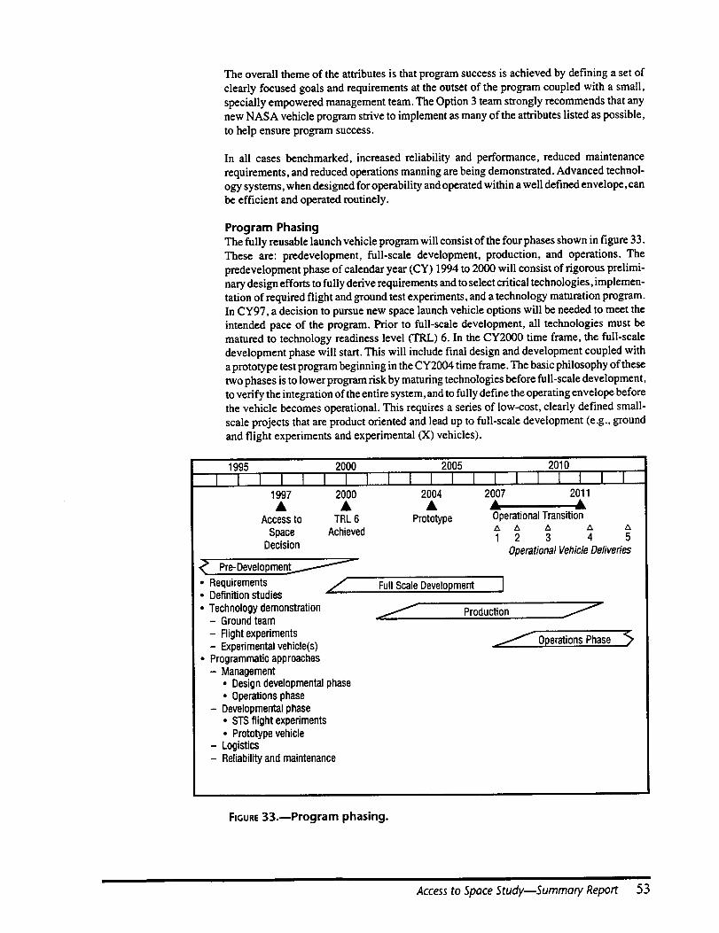
Theoverall theme of the attributes is that program success is achieved by defining a set of
clearly focused goals and requirements at the outset of the program coupled with a small,
specially empowered management team. The Option 3 team strongly recommends that any
new NASA vehicle program strive to implement as many of the attributes listed as possible,
to help ensure program success.
In all cases benchmarked, increased reliability and performance, reduced maintenance
requirements, and reduced operations manning are being demonstrated. Advanced technol-ogy systems, when designed for operability and operated within a well defined envelope, can
be efficient and operated routinely.
Program Phasing
The fully reusable launch vehicle program will consist of the four phases shown in figure 33.
These are: predevelopment, full-scale development, production, and operations. The
predevelopment phase of calendar year (CY) 1994 to 2000 will consist of rigorous prelimi-nary design efforts to fully derive requirements and to select critical technologies, implemen-
tation of required flight and ground test experiments, and a technology maturation program.In CY97, a decision to pursue new space launch vehicle options will be needed to meet the
intended pace of the program. Prior to full-scale development, all technologies must bematured to technology readiness level (TRL) 6. In the CY2000 time frame, the full-scale
development phase will start. This will include final design and development coupled with
a prototype test program beginning in the CY2004 time frame. The basic philosophy of these
two phases is to lower program risk by maturing technologies before full-scale development,to verify the integration of the entire system, and to fully define the operating envelope before
the vehicle becomes operational. This requires a series of low-cost, clearly defined small-
scale projects that are product oriented and lead up to full-scale development (e.g., ground
and flight experiments and experimental (X) vehicles).
1995 2000 2005 2010
I I I I I I I I I I I I I I I I I I I I1997 2000 2004 2007 2011
Accessto TRL 6
Space AchievedDecision
_> Pre-Developmen_
• Requirements /• Definitionstudies• Technologydemonstration
- Groundteam
- Flightexperiments- Experimentalvehicle(s)
• Programmaticapproaches- Management
• Designdevelopmentalphase• Operationsphase
- Developmentalphase• STSflight experiments• Prototypevehicle
- Logistics- Reliabilityand maintenance
• __A -Prototype OperationalTransition
A Z_ Z_ A Z_
1 2 3 4 5
OperationalVehicleDeliveries
FullScaleDevelopment I
.,...../ Production /
/ OperationsPhase <2
FIGURE33.--Program phasing.
I
Access to Space Study--Summary Report 53

The production phase will overlap the full-scale development and operations phases. At the
end of the development phase, the new vehicle will be turned over to an operating
organization. The CY2007 to 2009 time frame will serve to transition operations from the
Space Shuttle fleet to the new vehicle fleet. No preplanned product improvements will be
pursued. The only changes allowed on the new vehicle will be those required due to a defect
or those that can be shown to pay for themselves in a reasonable period.
Technology PlanAn Agency-wide subteam was established to assess current subsystem technology maturity
levels for the three representative vehicle design options. The principal product of this
subteam was the documentation of a plan to mature these technologies to a readiness level
value of 6 by CY2000. Technology readiness level 6 is defined as "successful system/
subsystem model or prototype demonstration in a relevant environment (ground or space)."
The subteam has several working groups that consist of structures and materials, thermal
protection system, propulsion, aerosciences, avionics, and operational specialists. The total
technology plan was estimated to require $9(X)M over 5 years.
The result is a prioritized plan that identifies both enabling (requisite) and enhancing
(upgrading) technologies. A core set of enabling technologies common to all three advancedtechnology concepts was also identified. These are discussed below.
Reusable Cryogenic Tanks
A common element of fully reusable vehicles that has not been explored in any depth in prior
technology efforts is the development of long life/low maintenance/operable reusablecryogenic tank systems. The cryogenic tank system includes both the tank structure and
insulation (both cryogenic and aerothermal). Included in this task are the development of tankcertification criteria; nondestructive evaluation (NDE) techniques; establishment of a
materials data base; optimization of materials processing and fabrication; the design,
fabrication, and analysis of a large-scale cryogenic tank system including structural and
thermal cycling; and incorporation of vehicle health monitoring.
Vehicle Health Management and Monitoring
Vehicle health management and monitoring, while being successfully and widely utilized on
high-performance military and commercial aircraft, is not nearly as mature on domestic
space launch systems, with the exception of certain subsystems on the Space Shuttle.
Application of these existing techniques to launch vehicles permits real-time identificationand rectification of vehicle subsystem anomalies. Definition of critical items to be monitored
and stored, development of data transfer techniques, "smart" management algorithms, and
development of ground processing procedures, including responsive maintenance capabili-ties, are included in this area.
Autonomous Flight Control
To achieve low cost space transportation, most in-flight functions must be automated and
control responsibility transferred to the vehicle. Autonomous flight control is both possible
and near state of the art for ascent, re-entry and landing. On-orbit operations, such as routinerendezvous and docking at the Space Station, are also near state of the art and are under
development by NASA. The technology objective is to develop and demonstrate theseintegrated techniques.
Operations Enhancement Technologies
The focus on low operations cost approaches for launch systems has resulted in an assessmentof operations requirements derived from a series of studies and benchmark evaluations.
Several key areas requiring further investigation include: operable and reliable rocketengines, leak-free propellant feed valves and joints, electro-mechanical actuators, andelectrohydraulic actuators.
54

Long Life/Low Maintenance Thermal Protection System
The development of a long-life/low-maintenance thermal protection system is required to
decrease the operational costs of reusable vehicles. Tasks to investigate metallic concepts,toughened rigid ceramic insulation, advanced flexible blanket insulation, carbon/silicon-carbide hot structures, and direct-bond reusable surface insulation are included in this area.
High Priority Vehicle-Unique Technology/Advanced DevelopmentFor the single-stage-to-orbit all-rocket concept, the key technology requirement is for the
development of a long life, low maintenance, tripropellant engine generally based on theRussian RD--704 design. An alternate approach would be the development of appropriate
technologies for an advanced lox/LH2 engine derived from the Space Shuttle main engine.
CostsThis section includes Option 3 cost estimates over the life of the program. All transportation
costs to launch NASA and Department of Defense payloads from 1994 to 2030 are included.
The life-cycle costs include: the cost of operating current systems (Space Transportation
System, Titan IV, Atlas, Delta) from 1994 until replacement; technology, design, develop-ment, test, and evaluation; facilities; vehicle fleet production (including production of
vehicles for anticipated reliability losses); and recurring operations. In addition to the vehicle
costs, the design, development, test, and evaluation, and production costs for a crew rotation
module and an upper stage are included.
Design, development, test, evaluation, and production estimates are business-as-usual
estimates and take no credit for potential cost savings that can be achieved by using new ways
of doing business or more efficient management or procurement approaches (e.g., "SkunkWorks"). A savings of 30--40 percent over these numbers could be expected if such new ways
were adopted. Operations cost estimates do require a significant departure from the currentSpace Transportation System operations culture and reflect the ground rules and philosophydetailed earlier.
Table 7 shows the total cost from 1994 to 2030 of each cost element for the two options of
the single-stage-to-orbit all-rocket vehicle using the RD-704 engine. Note that the 45-foot
payload bay vehicle has significantly lower expendable launch vehicle costs since it wasassumed to replace the Titan IV as well as all other current vehicles.
Figure 34 shows the cost profile from 1994 to 2030 for the architecture featuring the single-
stage-to-orbit all-rocket vehicle using the RD-704 engines with a 45-foot payload bay.
Option 3 Team Findings
Comparison Against Criteria
The single-stage-to-orbit all-rocket vehicle meets the fundamental requirement establishedat the outset of the study to satisfy the national launch needs. The focus of the study was in
defining a 25k-pound class of launcher since approximately 90 percent of all future payloads
fall into this category. The advanced technology vehicle will replace all Delta- and Atlas-
class missions and meet Space Station logistics resupply and return requirements (cargo andcrewed). The vehicle is capable of performing on-orbit payload servicing missions when
required. The tripropellant aspect also allows for an option to carry a 45-foot long payload
bay to accommodate Titan IV-class payloads.
The single-stage-to-orbit all-rocket vehicle also has the potential for increasing crew safety
and vehicle reliability. The vehicle is capable of performing a return-to-launch-site maneuver
with one engine failure on the launch pad. Abort with multi-engine failures is possible during
the ascent phase. In the crewed configuration, the crew pressure vessel is designed to survive
a catastrophic failure, with ejection seats for escape. Avionics fault tolerance is fail op/fail
safe. Engine shutdown is possible due to all liquid propulsion. Reliability is also enhanced
through the use of a single airframe, which inherently reduces the number of vehicle systems.
Access to Space Study--Summary Report 55

TABLE7.--Single-stage-to-orbit oil rocket vehicle costs
Total Costs($B) FY94-FY2030*
SSTO(R) (RD-704)
TechnologyDevelopmentDDT&E
• Vehicle• CrewRotationModule
•UpperStageFacilities
30-It PayloadBay
0.916.713.92.20.6
45-It Payload Bay
0.917.114,32.20.6
0.6 0.6Production 18.1 18.7
• Vehicle 12.6 13.2• CrewRotationModule 0.8 0.8
4.7 4.7• EngineOperations
• Vehicle• STS-ELV
• UpperStageTotal
181.723.949.185.8
2.9
131.923.949.156.02.9
198.0 169.2
Dollaramountsgivenin FY94values.
=E
m
_L
14,000
12,000
10,000
8,000
6,000
llllllllllllllllllllllll
fill I
4,000
2,000
FmURE34.--Access to Space Option 3 single-stage-to-orbit all rocket
total cost spread.
56
The focus of the Option 3 effort was on reducing annual operations costs. The single-stage-
to-orbit all rocket annual operating costs are estimated to be approximately one-third that of
the Space Shuttle. This is possible through the use of a single, fully reusable airframe coupled
with changes in the space launch operations culture. Development costs of approximately
$18B were estimated using a NASA business-as-usual approach and appear reasonable for
this type of system. A 30--40 percent reduction could be expected with new ways of doing
business. Even without flying the Titan IV payload missions, payback on the initial
investment will occur approximately 9 years from initial operating capability. Risk is
mitigated though the use of evolutionary technologies based on proven systems and a
technology maturation program prior to initiation of full scale development, coupled with a
prototype test vehicle to reduce both technical and programmatic risk. If the technologies do
not mature prior to full-scale development, the option exists for terminating future develop-
ment and applying the technologies to the existing expendable and Shuttle launch vehiclefleets.
A high flight rate coupled with full reusability will yield cost-effective and competitive space
access for commercial payloads. The Option 3 recommended program is focused on
technology development and application that will result in a significant technology data base
for use by the private sector. Potential dual-use technologies include applications to existing
and future launch systems and high-strength/lightweight composite structures.
SummaryThe Option 3 team has defined a strategy to meet reduced cost future space transportation
needs, with a primary focus on improving reliability, crew safety, and operability. An
approach has been defined that will offer significant reductions in annual operations costs.
The advanced technology approach, Option 3, meets these needs by defining a transportationarchitecture that contains an all rocket single-stage-to-orbit launch vehicle to accommodate
both Space Station resupply and 25,000 to 41,000 pound cargo delivery and satellite
deployment missions (NASA, DOD, and commercial) in CY2008, as well as an interim
expendable launch vehicle program that upgrades the existing Delta, Atlas, and Titan fleetin the CY2000 to 2008 time frame. The final architecture of Option 3 is shown in figure 35.
Based on preliminary evaluations, single-stage-to-orbit v6hicles appear to be feasible
because of reduced sensitivity to engine performance and weight growth resulting from use
of near term advanced technologies (e.g., tripropellant main propulsion, A1-Li and graphite
composite cryogenic tanks, graphite-composite primary structure, etc.). An incremental
approach has been laid out to reduce both technical and programmatic risk. This includesmaturing the required technologies to a technology readiness level of 6 prior to full-scale
development (i.e., ground tests and experimental vehicles) and conducting a prototype flight
test program that will define the operational envelope of the vehicle and thus certify the
design for production and operations.
Access to Space Study--Summary Report 57
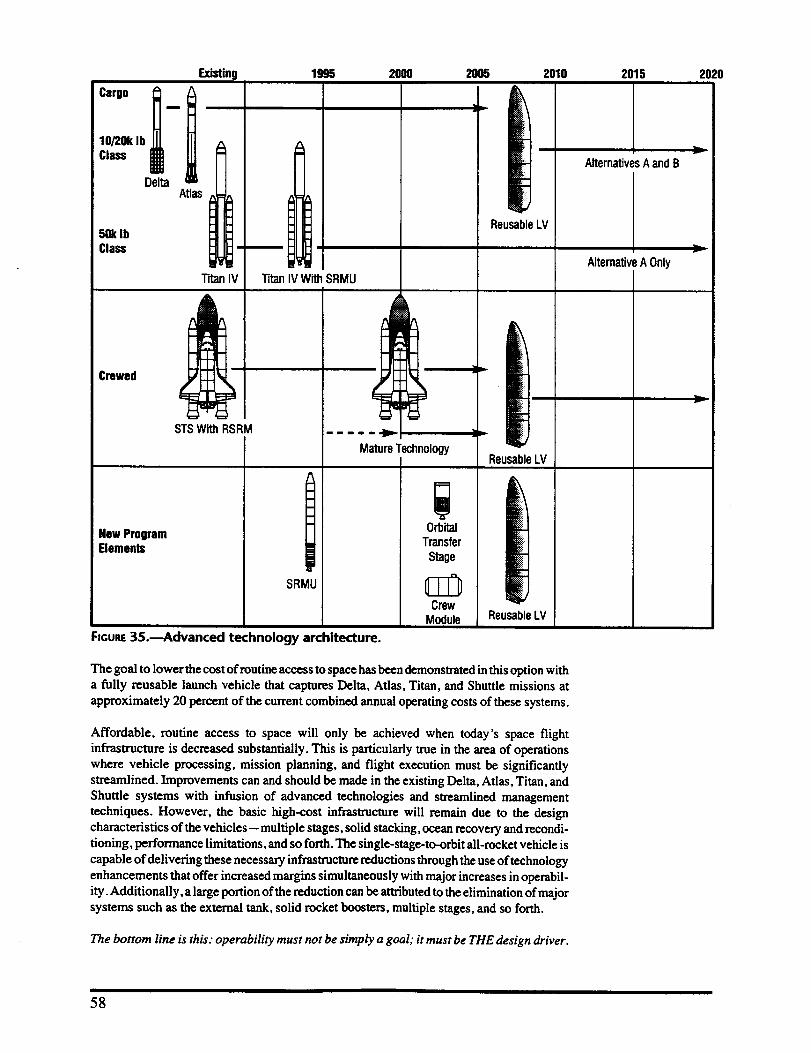
Existing
Cargo I:
"1
Class
Delta
501(IbClass
Crewed
Hew ProgramElements
i I :
Atlas: .-..
1995
STS With RSRM
TCln IV With SRMU
|F
SRMU
2000 2005
FIGURE35.--Advanced technology architecture.
m m m m | im]il),,
MatureTechnologyI
]1|
OrbitalTransfer
Stage
CrewModule
2010
m
ReusableLV
ReusableLV
ReusableLV
2015
AlternativesA and B
AlternativeA Only
The goal to lower the costof routine accessto space hasbeen demonstrated in this option witha fully reusable launch vehicle that captures Delta, Atlas, Titan, and Shuttle missions at
approximately 20 percent of the current combined annual operating costsof thesesystems.
Affordable, routine access to space will only be achieved when today's space flight
infrastructure is decreased substantially. This is particularly true in the area of operations
where vehicle processing, mission planning, and flight execution must be significandy
streamlined. Improvements can and should be made in the existing Delta, Atlas, Titan, and
Shuttle systems with infusion of advanced technologies and streamlined management
techniques. However, the basic high-cost infrastructure will remain due to the design
characteristics of the vehicles-- multiple stages, solid stacking, ocean recovery and recondi-tioning, performance limitations, and so forth. The single-stage-to-orbit all-rocket vehicle is
capable of delivering these necessary infrastructure reductions through the use of technology
enhancements that offer increased margins simultaneously with major increases in operabil-
ity. Additionally, a large portion of the reduction can be attributed to the elimination of major
systems such as the external tank, solid rocket boosters, multiple stages, and so forth.
The bottom line is this: operability must not be simply a goal; it must be THE design driver.
2020
r
v
58
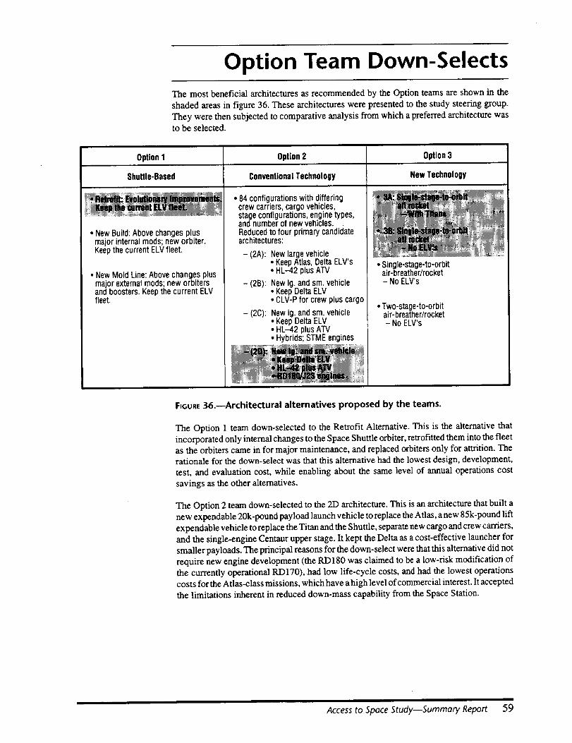
Option Team Down-Selects
The most beneficial architectures as recommended by the Option teams are shown in the
shaded areas in figure 36. These architectures were presented to the study steering group.
They were then subjected to comparative analysis from which a preferred architecture wasto be selected.
Option1
Shuttle-Based
• NewBuild: Above changes plusmajor internal mods; new orbiter.
Option2 Option3
ConventionalTechnology NewTechnology
• 84 configurations with differingcrew carriers, cargo vehicles,stage configurations, enginetypes,and number of new vehicles.Reducedto four primary candidatearchitectures:
KeepthecurrentELV fleet.
• New Mold Line: Above changesplusmajor external mods; new orbitersand boosters Keepthe current ELVfleet.
- (2A): Newlarge vehicle* KeepAtlas, Delta ELV's• HL-42 plus ATV
- (2B): New Ig. and sin. vehicle• KeepDelta ELV• CLV-Pfor crew plus cargo
- (2C): New Ig. and sin. vehicle• KeepDelta ELV• HL-42 plus ATV• Hybrids; STMEengines
_:!b-%.< _. ._ .....................
• Single-stage-to-orbitair-breather/rocket- No ELV's
• Two-stage-to-orbitair-breather/rocket- No ELV's
FIGURE36.--Architectural alternatives proposed by the teams.
The Option 1 team down-selected to the Retrofit Alternative. This is the alternative that
incorporated only internal changes to the Space Shuttle orbiter, retrofitted them into the fleetas the orbiters came in for major maintenance, and replaced orbiters only for attrition. Therationale for the down-select was that this alternative had the lowest design, development,
test, and evaluation cost, while enabling about the same level of annual operations cost
savings as the other alternatives.
The Option 2 team down-selected to the 2D architecture. This is an architecture that built a
new expendable 20k-pound payload launch vehicle to replace the Atlas, a new 85k-pound lift
expendable vehicle to replace the Titan and the Shuttle, separate new cargo and crew carriers,
and the single-engine Centaur upper stage. It kept the Delta as a cost-effective launcher for
smaller payloads. The principal reasons for the down-select were that this alternative did not
require new engine development (the RD180 was claimed to be a low-risk modification ofthe currently operational RD170), had low life-cycle costs, and had the lowest operationscosts for the Atlas-class missions, which have a high level of commercial interest. It accepted
the limitations inherent in reduced down-mass capability from the Space Station.
Access to Space Study--Summary Report 59

The Option 3 team down-selected to an all-rocket, fully reusable single-stage-to-orbit
vehicle. The recommended configuration for this vehicle incorporated a tripropellaat
propulsion system, graphite-composite structure, aluminum-lithium propellant tanks, and an
advanced thermal protection system and subsystems. Added margin could be attained byusing graphite-composite fuel tanks rather than those made with aluminum-lithium fuel
tanks. Rocket vehicles were selected over air-breathing vehicles on the basis that they had
lower design, development, test, and evaluation costs; lower technology phase costs; and
required less demanding technology that would translate into a more quickly developed and
less risky program.
Two versions of the single-stage-to-orbit rocket were recommended. The first (Option 3A)
had a transverse payload bay 15 feet in diameter and 30-feet long, which could not
accommodate the largest of the Titan-class missions. This architecture thus required
continuation of the Titan expendable launch vehicles in parallel with the new vehicle
operations. The second version of the single-stage-to-orbit rocket vehicle (Option 3B) hada 45-feet long longitudinal payload bay that could accommodate all Titan payloads if some
were somewhat downsized (a plan which is under serious consideration within the Depart-
ment of Defense), and thus would not require continuation of expendable launch vehicles as
part of the architecture. This version was included because of the high costs of operating the
Titan expendable launch vehicle.
60

New Operations Concept
All the option teams recognized that if large savings in annual costs were to be realized, new
management, contracting, design, development, and, particularly, operations concepts had
to be devised. The fundamental change required was that all phases had to be driven by
efficient operations rather than by attainment of maximum performance levels. This, in turn,
required maximizing automation and minimizing the number of people in the "standing
army" on the ground, as well as requiring redundancy, engine-out capability, and robust
margins in all subsystems. In addition, both of the Options 2 and 3 teams recommended
avoiding development of new technology in parallel with vehicle development in order to
minimize program risks and cost growth.
The Options 2 and 3 teams recommended a streamlined management and contracting
approach patterned after the Lockheed "Skunk Works," which features smaller, but dedi-
cated and collocated government oversight, a more efficient contractor internal organization,
rapid prototyping, and team continuity from design to flight.
The recommendations also included a number of specific operations-oriented items, some of
which are applicable to reusable vehicles and others that apply to both expendable andreusable vehicle operations. They included using well-matured technologies, demonstrated
through a number of flights of an experimental vehicle; demonstration and validation of
vehicle design via flights of a full-scale prototype, with gradual stretching of the flight
envelope; certification of the vehicle design and type-certification of the fleet; avoiding
continual engineering changes and long-term development engineering overhead by freezing
the design for long periods between block changes; avoiding most detailed inspection andmaintenance after each flight unless the need is clearly indicated by an onboard health
monitoring and reporting system, or if the immediately previous flight exceeded the flight
envelope limits charted in the prototype program; operating the single-stage-to-orbit fleet
using a depot maintenance philosophy in which maintenance is only done by exception or
every 1 to 2 years; use of small, dedicated ground crews led by a crew chief empowered tomake all decisions in operations and maintenance; a reduced ratio of nontouch to touch labor
compared to that utilized in today's operations; and much use of automation on the ground,as well as in the vehicle. These amount to a complete change in the way vehicles are
developed and operated compared to current practice, and are patterned after several high-
performance aircraft programs.
In the aggregate, the above recommendations amount to a "new way of doing business,"
which was recognized as being essential if low operating costs were to be realized. Itsattainment would be a major shift from today's practices in launch vehicle operations.
Access to Space StudymSummary Report 61

Comparative Analysis
The down-selected architectures were compared so that a decision could be made on the most
attractive option. The major factors considered in the evaluation were design, development,
test, and evaluation costs; operations costs; life-cycle costs; and the safety and reliability ofthe concepts. These and other factors considered followed the major evaluation criteria
identified in the Purpose section.
Costs Assessment
The costs presented in this report were developed from a common set of ground rules
developed by the Comptroller's Office and are predicated on the technical complexity,
operability, and flight-related assumptions of each of the option teams. The costs of the
recommended architectures were analyzed, with design, development, test, and evaluation
and total program costs treated separately. All cost figures are shown in constant FY94 dollars
and in a business-as-usual mode, that is, without incorporation of the operations ormanagement changes discussed in the New Operations Concepts section. This is because the
NASA cost models were designed around the historical data base, and NASA does not have
a mature basis for estimating costs incurred in a different culture.
The NASA Comptroller assembled a cost team to attempt to estimate the savings that mightaccrue if new ways of doing business were adopted, and this team concluded that a 30 to 40
percent reduction of the costs shown might be expected operating in such a mode. However,
the cost team felt that since each of the options benefited differently from changes in culture,
the comparison of the different options would be best served by using the business-as-usualmethod and then applying estimated reduction factors.
The design, development, test, and evaluation costs of the three options are shown infigure 37. These curves include a technology phase for Option 3. The curves are annotated
with a callout indicating the total technology, design, development, test, and evaluation costs,
which are $2.4B for Option 1; $11.1B for Option 2; and $17.6 and $18B for Options 3A and
3B, respectively. These curves do not include facilities, production, or operations. If the new
ways of doing business were adopted, these costs could be as much as 30 to 40 percent lower,
or $1.5 to $1.7B for option 1; $6.7 to $7.7B for Option 2; and $10.6 to $12.6B for Option 3.
The profiles of these technology, design, development, test, and evaluation expenditures
are very different. Options I and 2 require large budgets essentially immediately, while
Option 3 has a 4 to 5 year technology phase funded at relatively modest levels before the largebudget requirements start. This technology phase requires $900M over 5 years and has an
annual peak of about $240M. The profiles of options 3A and 3B are essentially the same.
The life cycle cost profiles of the three options are shown through the year 2030 in
figure 38. These are total costs for the entire period to deliver the mission model of the
Approach, Ground Rules, and Organization section, and include the technology, design,development, test, and evaluation costs of figure 37. A fourth curve is included in
figure 38, labeled "current systems," which represents the cost to the U.S. Government if no
changes are made and the current systems are operated for the entire period. In 1995, this
current systems cost will be comprised of $3.8B for the Space Shuttle, $2.4B for the
Department of Defense expendable launch vehicles and infrastructure, and $0.5B for the
NASA expendable launch vehicles, totaling $6.7B.
62

Option3A ($17.6B)"-1
Option 39 ($18.0B)-_ I
----- i- ,"_. /--_--_Option 2 ($11.18)
_ _1: "/'./ \--_ l k J'f:"°_ "'', X Option1 ($2.4B)¢= oL,,.'F_ r-.,, ";i _ I
1995 2000 2005 2010Year
FIGURE37. m Design, development, test, and evaluation costs of the options.
12
10
A 8==oiU
6
_m0
" 4
01995
(This informationapp/iesto bothfigures.)
• Commercialflight costsexcluded• Technologyphaseincluded• Constant FY94dollars• No creditfor "new ways of doingbusiness"• Alternativescosted:
Option1 - RetrofitAlternative STSplusPegasus,Delta.Atlas.andTitan
- Current upperstages
Option2D - Large andsmallnew vehiclesplus Pegasusand Delta
- Single engineCentaur upperstage,- Option 1 (DDT&E= $2.4B) Option 3A - SSTOtripropellantrocket(30-ft bay)
Option 2 (DDT&E= $11B) - TitanIV; plus new upperstage
_-- Option 3 (DDT&E= $18B) Option 3B - SSTOtripropellantrocket(45-ft bay)
t _ - New upperstage
_/".,_ .... - ...._,_'_'ii_'." X __._ .,CurrentSystems(Life-cyclecost(LCC)=$233B)
" - - "_'_ "--_ - - "_.--- - --"_-_ Option1 (LCC= $230B)
_DOD_LV's i........... X_',,.,_,__-NASA ELV's ...... _'""_ ................................................. Option 2 (LCC= $192B)
_-_STS_I oOpti°n3A (LCC=$198B)3B(LCC= $169B)
, , , , , , o_on2000 2005 2010 2015 2020 2025 2030
Year
FIGURE38.--Total U.S. Government launch costs.
Access to Space Study--Summary Report 63
This reference varies somewhat with the expendable launch vehicle annual buys, infrastruc-
ture investments, and programmed Shuttle improvements. It was assumed as a point of
reference that the expenditures remain essentially fixed after 2000, and that no additional
orbiters will be acquired through 2030, even though a replacement orbiter is likely to be
needed sometime during that interval. The life-cycle cost of this activity, if nothing is done
differently than today, is $233B through 2030.
The cost plot of the architecture of Option 1 shows the increase for the $2.4B investment,
followed by the $6.5B to retrofit the fleet, and then by a programmed buy of a replacement
orbiter in 2010. The annual realized savings in operations costs is only about $0.25B per year.
Its life-cycle costs are $230B. The investment in design, development, test, and evaluation
is recovered after 10 years of steady-state operations. The total investment including design,
development, test, and evaluation, and the replacement orbiter is recovered in slightly more
than 20 years of operation.
The cost plot of the architecture of Option 2 shows the investment of $11.1B in design,
development, test, and evaluation costs upon the immediate start of new vehicle develop-
ment, followed by a rapid reduction in the operations costs starting in 2005 when the new
vehicles are introduced and the Shuttle and most expendable launch vehicles are phased out.These vehicles are all phased out over 2 years. The operating costs are reduced to $4B
annually beginning in 2006. The life-cycle costs of Option 2 were $192B. The recovery time
for the investment in design, development, test, and evaluation is about 4 years of steady-state
operation. The recovery of the total design, development, test, and evaluation plus productioninvestment is about 5 years of steady-state operation.
The plot of the architecture of Option 3A shows the investment of $17.6B for technology,
design, development, test, and evaluation through 2008, with the start of the development
program delayed by about 5 years due to the technology maturation and demonstration phase.This option features the vehicle with the shorter payload bay, which requires continuation of
the Titan expendable launch vehicles in parallel.
The Option 3A architecture results in a steady-state operations cost of $2.6B per year. That
level is not achieved until after 2020 due to a deliberately slow production phase for thereusable vehicles and upper stages and their spares, which are all purchased continuously and
then the production line is shut down. These purchases are stretched over 10 years or more
to minimize peak funding needs. The technology, design, development, test, and evaluation
investment would be recovered in 4 JA years of steady-state operations, while recovery of the
total investment, including production of the vehicles, requires 9 years. The life-cycle cost
of Option 3A is $198B.
Option 3B has the longer payload bay and could carry all DOD payloads with some
downsizing, which the DOD may accomplish at the program's block change time in the f'_rstpart of the 2000 to 2010 time period. The cost profile for this option follows that of
Option 3A during development, but decreases to an annual operations cost of $1.4B since no
Titans need to be retained. The life-cycle cost for this option is $169B. The technology,design, development, test, and evaluation investment would be recovered in only 3 V2years
of steady-state operation, while recovery of the total investment would take only 7 years.
The clear message from figure 38 is that new vehicles are required if substantial savings are
desired, and that attaining the greatest savings requires the largest investment.
The most significant aspects of the costs of the three options, and some associated metrics,
are shown in figure 39. This figure displays the costs for the technology phase, the design,
development, test, and evaluation (including the technology phase), the production of one-
time or reusable hardware, the annual operations costs in the out-years, and the life-cyclecosts.
64

Costs
OperationsCostMetrics**
In addition to the previous observations, it is important to note that if nothing is done
differently, the U.S. Government will spend $233B for space launch through 2030 for theassumed mission model of section 2. Option 1 only reduces that total by $3B over 35 years.
Option 2 reduces the life-cycle cost by $41B in non-discounted dollars, or 17.6 percent.Option 3A reduces the life-cyc]e cost by $35B, or 15 percent. Option 3B reduces the life-cycle
cost by $64B, or 27.5 percent.
Thus, the life-cycle cost savings for Option 3B are the greatest of all of the options, averaging
a savings of $1.8B per year over the 35 year period through 2030.
Technology
DDT&E(Incl. Technology)
Production
Operations(Out-Years)
Life-Cycle Costs
Average S/Launch(Shuttle Replacement)
$/110of PayloadleetAverage forission Model)
$/lb of Payload(Full Veh., to LEO,28°)
$/110of Payload(to the Space Station)
CurrentProgram
Option1(Retrofit+ELVFleet)
Incl. inDDT&E
Option2(Lg. + Sin. Veh.
+ Delta)
Option3
(SSTO-R,30-ftBay + Titan)
(SSTO-R,45-ft Bay)
0 $0.4B $0.9B $0.9B
0 $2.4B $11.1B $17.6B $18B
0 $5.6B $2.0B $18.1B $18.7B
$6.4B/yr $6.1 B/yr $4.0B/yr $2.6B/yr $1.4B/yr
$233B $230B $192B $198B $169B
$293M(STS)*
$322M(STS)*
$85M (Sm.)$205M (Lg.)
$41M $38M
$7,488/Ib $6,814/Ib $6,100/lb $3,900/Ib $2,100/Ib
$6,850/110 $6,234/11) $3,900/Ib (Sm.)(STS)* (STS)* $1,600/110(Lg.) $980/lb $920/Ib
$12,880/Ib $11,720/Ib $3,700/Ib (Lo.) $1,600/lb $1,500/Ib
* CurrentSpace Shuttle capability(no ASRM)** In the out-years• Constant FY94dollars; no "newways of doingbusiness."
FIGURE39.--Summary of option costs.
Referring to the cost metrics portion of the figure 39, it is shown that the fleet-average launchcosts for the mission model were reduced from the current values of $7,488 per pound to
$6,814 per pound for Option 1; $6,100 per pound for Option 2; $3,900 per pound for Option3A, and to $2,100 per pound for Option 3B. The lowest cost per pound of payload for the new
vehicles launching into a 28-degree inclination low orbit were $920 and $980 per pound for
the two Option 3 cases. Next higher were the $1,600 per pound to $3,900 per pound for the
two different sized vehicles in Option 2, with the commercially significant smaller vehicle
having the larger cost per pound. The cost for Option 1 was $6,234 per pound.
The Space Shuttle costs per launch were calculated consistent with the methodology
historically presented to OMB and GAO. While all the costs were lower than the $6,850 to
$7,488 per pound for the current Shuttle program when computed the same way, it is clear
that the major cost savings targeted as a goal for this study only accrue in architectures
employing new vehicles. In addition, it is also clear that Option 3 lowers the launch costs by
the largest amount.
Access to Space Study--Summary Report 65
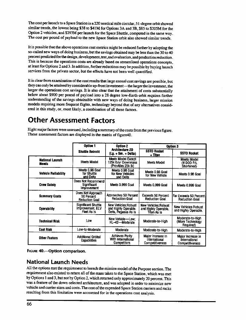
The cost per launch to a Space Station in a220 nautical mile circular, 51-degree orbit showed
similar trends, the lowest being $38 to $41M for Options 3A and 3B, $85 to $205M for the
Option 2 vehicles, and $293M per launch for the Space Shuttle, computed in the same way.The cost per pound of payload to the new Space Station orbit also showed similar trends.
It is possible that the above operations cost meuics might be reduced further by adopting theso-called new ways of doing business, but the savings obtained may be less than the 30 to 40
percent predicted for the design, development, test, and evaluation, and production reduction.
This is because the operations costs are already based on streamlined operations concepts,
at least for Options 2 and 3. In addition, further reductions may be possible by buying launch
services from the private sector, but the effects have not been well quantified.
It is clear from examination of the cost results that large annual cost savings are possible, butthey can only be attained by considerable up-front investment--the larger the investment, the
larger the operations cost savings. It is also clear that the attainment of costs substantially
below about $900 per pound of payload into a 28 degree low-Earth orbit requires furtherunderstanding of the savings obtainable with new ways of doing business, larger mission
models requiring more frequent flights, technology beyond that of any alternatives consid-ered in this study, or, most likely, a combination of all these factors.
Other Assessment Factors
Eight major factors were assessed, including asummary of the costs from the previous figure.These assessment factors are displayed in the matrix of figure40.
NationalLaunchNeeds
VehicleReliability
CrewSafety
SummaryCosts
Operability
OptionI OpHon2Architecture2D
ShuttleRetrofit (Lg. + Sm. + Delta)
MeetsModel
Meets0.98 Goalfor ShuttleandQQIto
DoesNotRecommendSignificant
Improvement
DoesNotApproach50Percent
ReductionGoal
SignificantShuttleImprovement.ELV
FleetAsIs
MeetsModelExcept125klb/yrDownmass
(Provides25k Ib)Meets0.98 Goalfor NewVehicles
andDelta
Meets0.999 Goal
Approaches50 PercentReductionGoal
NewVehicles:RobustandHighlyOperable.Delta,PegasusAs Is
SSTORocket+ Titan
OpUon3
SSTORocket
MeetsModelf DODP/Lhortened)
MeetsModel
Meets0.98 Goalfor NewVehicle Meets0.98 Goal
Meets0.999Goal Meets0.999Goal
Exceeds50 PercentReductionGoal
NewVehicles:RobustandHighlyOperable.
Titan As Is
FarExceeds50 PercentReductionGoal
NewVehicles:RobustandHighlyOperable.
TechnicalRisk
CostRisk
OtherFactors
Low
Low-to-Moderate
AdditionalOrbitalCapabilities
NewVehicle--Low;HL-42---Moderate
Moderate
AchievesParityWithInternational
Competitors
Moderate-to-High
Moderate-to-High
MajorIncreaseinInternational
Competitiveness
Moderate-to-High(More Technology
Required)
Moderate-to-High
MajorincreaseinInternational
Competitiveness
FIGURE40._ption compadson.
National Launch Needs
All the options met the requirement to launch the mission model of the Purpose section. Therequirement also existed to return all of the mass taken to the Space Station, which was met
by Options 1and 3, but not by Option 2, which returned only approximately 20 percent. Thiswas a feature of the down-selected architecture, and was adopted in order to minimize new
vehicle and carder sizes and costs. The cost of the expended Space Station carriers and racks
resulting from this limitation were accounted for in the operations cost analysis.
66
An additional factor applied to Option 3B, which was able to launch the longest DOD
payloads only if the DOD downsized them to 45-feet in length. Preliminary discussions withthe DOD indicated that such downsizing was a distinct possibility at the time the payloads
were due for a block change, about 2002. Indeed, there has already been some Congressional
language urging the DOD in this direction in order to allow retirement of the expensive Titan
vehicles. Thus, while the possibility of having shorter payloads might be realistic, nonethe-
less, the viability of Option 3B rests on this assumption.
Vehicle ReliabilityAll vehicles except the Atlas and Titan met the goal of having a vehicle reliability greater than0.98 percent. It was felt that it was unlikely that these two expendable launch vehicles could
be upgraded to that reliability in a cost-effective way, while the Delta is almost at this
reliability level already. All the new vehicles were designed to exceed this requirement.
Crew SafetyThe improvement of crew safety (probability of crew survival) to at least 0.999 from the 0.98
of the Space Shuttle was met or exceeded by the new vehicles of Options 2 and 3. Option 2had a launch escape propulsion system for the entire crew carder, while Option 3 adopted
escape seats and intact abort of the vehicle into orbit or return to the launch site.
Option 1 did not recommend the addition of escape seats, an escape pod, or liquid boostersto the Shuttle and, thus, did not improve significantly on the current crew safety analysis. Thereason for this recommendation was that the analysis showed that the expense for
incorporation of additional escape capabilities was high, and that there was a significant
impact on current vehicle capabilities due to factors such as a major shift in the orbiter center
of gravity.
Summary CostsThe costs discussed with reference to figure 39 indicate that Option 1 did not approach the
50 percent cost savings goal; Option 2 approached it,though it did not meet the goal, reducing
operations costs by about 37 percent; and both Option 3 alternatives exceeded that goal--
Option 3A reducing costs by 59 percent and Option 3B by 78 percent.
A number of observations were made regarding relative costs. One was the difficulty of
reconciling cost estimates for operational systems, which are well understood, with those for
new vehicles whose definition is still in the pre-PhaseA state.
Compounding that difficulty was an uncertainty in the amount of cost growth margin toinclude in the estimates, which, in existing systems, was felt to be largely governed by
external factors rather than inherent growth due to inadequate definition or design errors. The
teams questioned, therefore, whether the historical cost growth allowances using conven-tional NASA models are too conservative if new management schemes are to be adopted that
might better be able to shield the program from external factors.
An additional observation is that the NASA cost models are designed to predict development
costs and lack a rigorous process for predicting operations costs. Nevertheless, the estimates
developed for the Access to Space Study were made with guidance from experienced costing
teams using the best costing tools available.
OperabilityEnhancements in the operability of the three options were also assessed. Option 1 improved
the Shuttle operability somewhat, but that of the companion expendable launch vehicles was
unchanged. Thus, taken as a whole, the operability of Option 1 was not significantly
improved over the present situation.
Access to Space Study--Summary Report 67

All the new vehicles of Options 2 and 3 had designs, infrastructure, and operations conceptsspecifically tailored for operability and robustness, and associated significant reductions in
operations costs. However, Option 2 retained the Delta and Option 3A retained the Titan, and,
thus, their overall operabilities were thus somewhat degraded. Therefore, Option 3B
promised the best operability of the three options.
Technical Risk
It is apparent that the technical risk will increase with adoption of new design vehicles, andeven more so if new technology is utilized. Thus, the technical risks were assessed as low for
Option l, low for the new vehicles of Option 2 since their designs have been defined in detail
under the Advanced Launch System and National Launch Systems programs, moderate for
the HL-42 crew carrier vehicle of Option 2, and moderate to high for Option 3 due to the
incorporation of new technology. Even though Option 3 incorporates new technology, its risk
was felt to be manageable due to the 4 to 5 year technology maturation phase which would
develop and demonstrate the needed technologies to at least a level 6 technology readinesslevel (proven in their operating environment).
Cost RiskThe cost risk was principally due to the schedule impacts of technical uncertainties during
development. It was felt to be low to moderate for Option 1, moderate for Option 2, andmoderate to high for Options 3A and 3B, the latter driven largely by the presence of new
developments and new technology.
There was also a recognition that while the options that had new vehicles incurred greater cost
and schedule risk, this risk increased in proportion to the cost savings they would enable.
Other Factors
In addition to the factors assessed above, there are a number of other distinguishing featuresof the options that should be considered in making an architectural selection.
The first of these is the total capability of the Space Shuttle which, in addition to providinglaunch and return of payloads, has a capability to capture and repair spacecraft, and is also
a crewed orbital research and development facility with an orbital flight duration of at least2 weeks. These capabilities would not be replicated if Options 2 or 3 were to be selected, as
crewed orbital laboratory functions are to be assumed by the Space Station. However, if the
Space Station is not available, for whatever reason, this factor could have an overridingimportance.
Another such factor is the ability for the U.S. commercial launch industry to compete in the
international satellite launch market. Option 1 does nothing to improve the current situation.
Option 2 would achieve approximate parity with the projected prices of the Ariane IV and
Ariane V, the most efficient of the foreign systems, only after a lengthy development period.
Option 3, on the other hand, would lower launch costs so dramatically that U .S. industry could
underprice all competitors. The U.S. would likely capture, and once again dominate, the
international satellite launch market for a considerable period of time, utilizing these uniqueadvanced technology vehicles.
Lastly, it was recognized that providing two different means for assured access to space for
every important payload will be prohibitively expensive, no matter how desirable. One way
out of this dilemma is to recognize that the world has changed and that the international space
launch community now has the capability and reliability to function as a backup, forlaunching U.S. payloads in the case of extensive groundings of U.S. launch vehicles. Thus,
while some payloads would have to be designed to be compatible with more than one launch
vehicle, assured access to space may be attained by any of the options studied, without majoradditional investment, by proper agreements with other nations.
68
Observations and Conclusions
Assessment of the characteristics, performance, and costs of the architectures recommended
by the option teams led to a number of observations which, in turn, lead to the study
conclusions. These are presented below.
Cost Reductions and Safety Increases
The study determined that it is indeed possible to achieve the objectives of large reductions
of operations costs and increases in reliability and crew safety at the same time in the samearchitecture. It did not appear that reasonable modifications to the Space Shuttle could
achieve these objectives in a cost-effective manner, though a number of beneficial improve-
ments to the Shuttle system were identified.
New vehicles were required in the architectures to attain these objectives. These vehicles
could be constructed using either conventional or advanced technologies, with the conven-
tional technology vehicles approaching the 50 percent desired minimum operations cost
reduction (37 percent reduction), and the advanced technology vehicles greatly exceeding it
(up to 78 percent operations cost reduction).
Design, Development, Test,and Evaluation BudgetBoth current technology and new technology vehicles achieved the targeted operating cost
reductions only after sizable design, development, test, and evaluation budget invest-
ments. This budget investment was smaller, but immediate, for the Option 2 architecture
using current technology new launch vehicles and carriers. Both of the Option 3 architectures
required a larger design, development, test, and evaluation budget, but start of their
development was delayed 4 to 5 years as a result of the necessity of maturing anddemonstrating the required technologies. Thus, Option 3 is more consistent with projected
near-term budget availability.
Annual Operations CostsThe annual operations costs of the Option 3B architecture were the lowest of all, since the newvehicle replaced all the current generation launch vehicles which have large operations costs.
The achievement of these low operating costs was completely dependent on making large-
scale changes in the way vehicles are designed, developed, managed, contracted for, and
operated. It was concluded that associated designs must all be driven by operations, as well
as by performance, and that resulting architectures must also entail the major changes inlaunch infrastructure and operations "culture" referred to as "new ways of doing business."
Most Attractive OptionInview oftheabove,anarchitecturefeaturinga new advanced technologysingle-stage-to-
orbitpure-rocketlaunchvehiclewas recommended asthemost attractiveoption.Ithas the
greatestpotentialforreducingannualoperationscostsaswell aslife-cyclecosts,itwould
developimportantnew technologieswith dual-useinindustry(suchascompositevehicle
structuresforcarsand airplanes),itwould placetheU.S. inan extremelyadvantageous
positionwithrespecttointernationalcompetition,and would leapfrogtheU.S. intoa next-
generationlaunchcapability.
Access to Space StudywSummary Report 69
The preferred single-stage-to-orbit rocket alternative is that in which the vehicle is sized so
as to accommodate all payloads in the mission model,so as to avoid the need to carry current
Titan expendable launch vehicles in parallel. The lowest operations costs resulted from
selecting this single-stage-to-orbit pure-rocket vehicle as the focal point of the new launcharchitecture.
The large development costs associated with this new vehicle would be put off for at least 5years while the technology was being matured and demonstrated. This would allow at least
that time period for measured consideration of the decision to start a new vehicle program.
On the other hand, delaying the decision of which vehicle architecture to select by 4 or 5
years but not funding a focused technology phase will achieve nothing, since the lack of afocused technology program during that period will not reduce the risks of developing an
advanced technology vehicle. Therefore, the choices available in 4 to 5 years would be
exactly the same as those we face today.
Technology Maturationand Demonstration
The assessment that the best option is to develop a new, fully reusable, advanced technology
single-stage-to-orbit rocket launch vehicle is absolutely dependent on maturing and demon-strafing the required technologies before initiating development.
Though it is possible to start development right away and perform technology maturation and
demonstrationconcurrently, such an approach carries with it greater technical, schedule, and
cost risks. Further, it would immediately require large budgets, precluding the 4 to 5 yearsof relatively modest budgetary investment. However, once the required technologies are
matured and demonstrated at the subsystem/system level in the pertinent environment, the
perceived risk is much reduced and should be manageable.
The technologies that require maturation and demonstration include graphite-composite
reusable primary structures, aluminum-lithium and graphite-composite reusable cryogenicpropellant tanks, tripropellant or lox-hydrogen engines designed for robustness and operabil-
ity, low-maintenance intergral or standoff thermal protection systems, autonomous flightcontrol, vehicle health monitoring, and a number of operations-enhancing technologies.
These technologies must be demonstrated on the ground and through flights of an experimen-
tal rocket vehicle. Technologies that interact should be tested together, both on the ground
and in the experimental vehicle. A second objective of an experimental vehicle would be to
validate the vehicle design models that are used to predict the characteristics and performance
of single-stage-to-orbit rocket vehicles.
Technology ApplicabilityThe current expendable launch vehicles and the Space Shuttle will have to be operated for
at least another 10 tol5 years before new launch vehicles can be available. Improvements tothe fleet vehicles that significantly improve their operability and possibly reduce their
operating cost should continue to be considered for implementation.
7O
The technology program for the single-stage-to-orbit rocket would result in the evolution of
numerous capabilities and/or components/subsystems that could be directly applied to these
current launch vehicle systems. These could improve the operability and, to some degree, the
cost performance of the current generation expendable launch vehicle fleet and the SpaceShuttle until such time as the new vehicles became available to be phased in. The decision
to upgrade the current fleet can be incremental and independent from that to start the
technology program.
The new technologies will generally support the development of any type of new generation
launch vehicle, even if initiated further in the future. In addition, most of these technologies
are highly beneficial in their own right for applications throughout the civilian and defensecommunities and the commercial marketplace.
Space ShuttleEven though improvements to the Space Shuttle were identified and new vehicle designs
were conceived that potentially could improve its cost and safety, it was clear that the SpaceShuttle remains the world's most reliable launcher and is safe to fly utilizing today' s rigorous
processes until a next generation system becomes available.
The cost savings reported by the Option 1 team did not consider management or contract
infrastructure changes. These areas have the potential to offer additional cost reductionbenefits; however, considerations such as these were beyond the scope of the Access to Space
Study. Such studies may be appropriate and beneficial and, if so, should be undertaken by the
Space Shuttle Program. It is recognized that the Space Shuttle Program has already
emphasized operational efficiency improvements in its program.
Lastly, the Option 1 team recommended further studies of flyback, fully reusable liquid-
fueled boosters for the Space Shuttle in order to increase safety and potentially reduce costs.These studies should be performed to further develop the possible benefits such a configuration
might offer.
National Aerospace Plane
The selection of the rocket single-stage-to-orbit over the air-breathing single-stage vehicle
by the Option 3 team was done for significant cost, risk, and schedule considerations. The air-
breather option was determined to have more difficult technology and, therefore, would be
more costly and take longer to develop.
However, air-breathing launchers potentially offer a number of unique mission capabilities
in which they may have an advantage. These include launch into orbits with lower inclination
than the latitude of the launch site, performing synergetic plane changes in order to over fly
a given Earth location on successive orbits, and flexibility to perform single-orbit datacollection missions. In addition, their technology is applicable to future hypersonic aircraft,
both for civilian and defense applications.
Thus it was concluded that the National Aerospace Plane enabling technology program
should continue independently of any decision to proceed with development of a nearer-term
low-Earth orbit launch system.
Access to Space Study--Summary Report 71

Recommendations
The Access to Space Study makes a number of recommendations. These are summarizedbelow.
1. Adopt the development of an advanced technology, fully reusable single-stage-to-orbit
rocket vehicle as an Agency goal.
2. Pursue a technology maturation and demonstration program as a first phase of this
activity.
- The technologies developed should be aimed at a single-stage-to-orbit rocket usingtripropellant propulsion and advanced structures and materials. This program would
mature and demonstrate the technologies described in the Description of the Option
Teams Analysis (Option 3) section and summarized in the Observations andConclusions section.
- A complementary experimental rocket vehicle technology demonstration flightprogram should be pursued in parallel with the technology development activity.
- These activities should be paced so as to allow the earliest informed decision on
development of a full-scale vehicle.
3. The technology, advanced development, and experimental vehicle programs should becoordinated with the Department of Defense.
4, The Space Shuttle and the current expendable launch vehicle programs should be
continued. The most beneficial and cost-effective upgrades should be considered for
incorporation into these vehicles until the new single-stage-to-orbit vehicle becomesavailable.
5. Although the focus of these recommendations is a technology maturation and demon-
stration program, additional studies should be conducted in parallel. They include
system trade studies for the single-stage-to-orbit rocket vehicle configuration in order
to guide the technology activities, and assessment of a fiyback reusable liquid booster
concept for the Space Shuttle.
6. The National Aero-Space Plane enabling technology program should be continued as
a separate and distinct activity, as it contributes to future defense and civilian hypersonic
aircraft programs, and it has potentially unique future mission applications.
72