access chambers and maintenance shafts - holcim · access chambers and maintenance shafts 5 access...
TRANSCRIPT
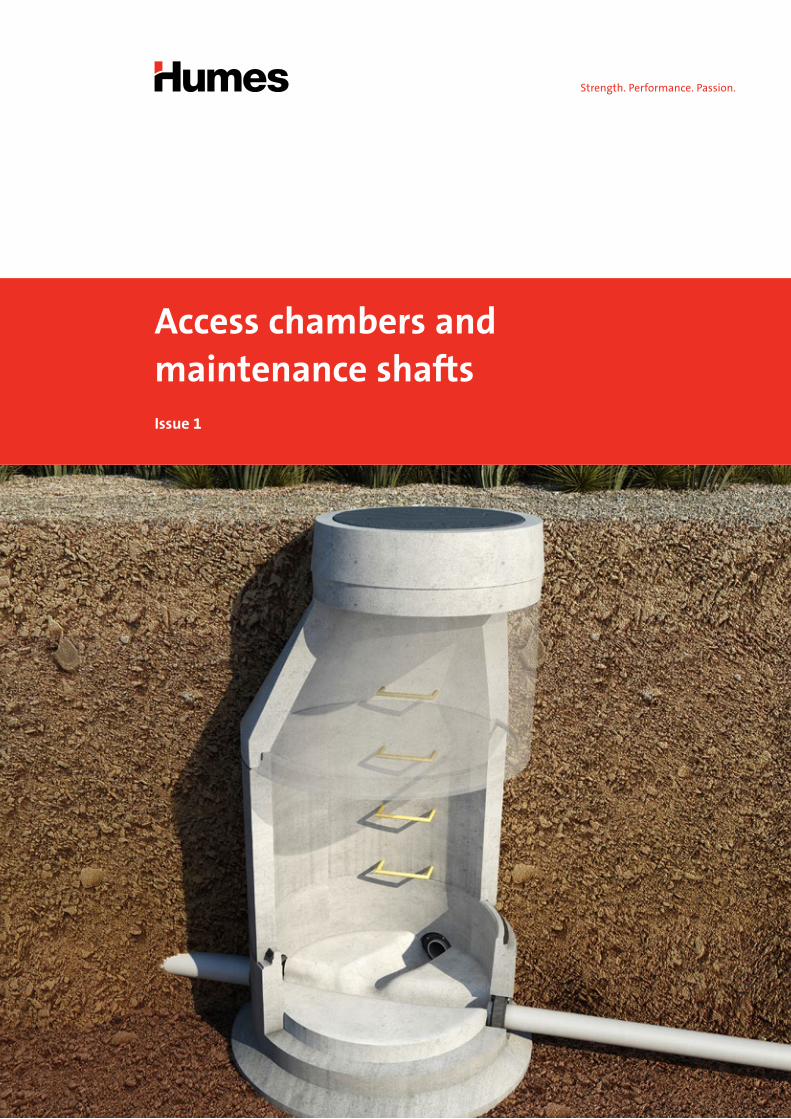
Access chambers and maintenance shaftsIssue 1
Contents
Access chambers (worker-entry) 1
Applications 2
Benefits 2
Design information 3
Components 3
Precast base 3
Shaft 3
Taper top (option one) 3
Squat top (option two) 3
Converter slab (option three) 3
Make up rings 3
Cover and surround 3
The Supabowl® conical precast base 5
HumeSeal® watertight coupling 5
Joint types 6
Wedge joint 6
Epoxy joint 6
Mastic joint 6
Maintenance shafts (non worker-entry) 7
The QuickTee® system 7
Precast solutions 8
Contact information 9

Access chambers or manholes are vertical shafts that
connect sewage transfer pipes to the surface to allow
worker-entry. Humes manufacture complete access
chamber structures to satisfy various local water codes,
practices and physical site conditions.
To address the issue of groundwater ingress a wedge ring
jointing system which provides a flexible watertight joint
is available.
Humes offer a range of precast access chambers,
with nominal sizes ranging from DN1050 to DN3600.
In addition, a range of components are available to
complete the access chamber structure for almost
any application.
Left:Access chamber structure ready for backfilling
Access chambers (worker-entry)
Humes provides a range of precast concrete sewer access chambers suitable for
depths up to 9 meters, in accordance with AS 4198-1994 Precast Concrete Access
Chambers for Sewerage Applications.
Access chambers and maintenance shafts 1
Acc
ess
cham
ber
s

Benefits
• Being precast, the need to pour concrete on site is
eliminated. This not only reduces the total number of
activities on site, but eliminates the in-situ base, which
can be a major cause of water infiltration within sewer
reticulation systems, if poor construction practices
are used.
• One crew can lay the pipe and the access chambers.
This improves labour and machinery efficiencies
on site, while improving installation time and
project costs.
• Backfilling the chambers can be coincidental with the
pipeline backfilling. This eliminates delayed backfilling
at access chambers, significantly reducing the time
that trenches are left open, which improves safety and
reduces risk.
• Given a stable soil foundation, bases require minimal
bed preparation and are simple to place, which reduces
dependence on specialist skills on site.
• HumeSeal® couplings make connecting pipes to
the base quick, flexible, watertight and reliable
(refer to page 5).
• Components can be supplied with Humes’
jointing system that is specific to the local market
(refer to page 6).
• Cored holes and precast benching can be placed at any
angle making the system capable of accommodating
all inlet configurations.
• Orders are usually supplied within three working days
of receiving drawings. This just-in-time manufacturing
process allows late changes in design.
• The installer is provided with a chamber-by-chamber
component breakdown of the project.
Applications
Humes’ access chambers are ideal for the following
applications:
• New residential and commercial developments.
• Joining into existing sewer lines.
• Sewer infill projects within established urban
areas where speed is of the essence to reduce
disruption to residents.
• Vacuum collection and isolation chambers.
• Air valve and scour pits, as well as overflow and
discharge chambers.
• Inspection and maintenance.
Below:1,100 mm precast base with factory benching
2 Access chambers and maintenance shafts
Components (refer to Figure 1 on page 4)
Precast base
The precast base is the foundation for Humes’ watertight
impermeable access chambers. Bases come in various
configurations and are available with factory benched
channels to suit specific site pipe geometry. Plain bases
are available where site benching is preferred.
The Supabowl® conical base which has an internal
surface in the shape of an inverted cone is another option
(refer to page 5 for further information).
Shaft
The chamber sections are manufactured in a standard
range of heights. Shaft sections are generally selected in
maximum individual heights to minimise handling and
jointing on site. The most common diameter used for
reticulation sewer works is 1,100 mm however, chamber
diameters vary with local geographic requirements.
Taper top (option one)
Where access chambers are greater than 1,200 mm
in depth the taper top provides a vertical wall that
corresponds to the chamber wall. The taper top may be
supplied with step irons which continue to the chamber
step irons to form access to the structure.
Ladders may be used in lieu of step irons where
approved by local authorities. The taper top is
configured with a wedge joint where applicable,
for other joint options see page 6.
Design information
Squat top (option two)
With an effective height of 300 mm, this is a concentric
tapered cone and provides entry to access chambers
which are shallow and do not require ladders or step
irons. They are generally used in applications less than
1,200 mm in depth where approved by the water
authority. The squat top is configured with a wedge joint
where applicable, for other joint options see page 6.
Converter slab (option three)
This slab converts the diameter of the chamber
(e.g. 1,100 mm) down to the dimensions which
will coincide with the surface cover and surround
(e.g. 600 mm) or make up rings. It may be used in place of
the squat top or taper top when additional headroom is
required. The converter slab is configured with a wedge
joint where applicable, for other joint options see page 6.
Make up rings
The make up rings facilitate the construction of the top
of the structure (refer to Figure 1 on page 4) relative
to the finished surface level and are available in
100, 150 and 200 mm thicknesses. They may be joined
with an elastomeric seal or epoxy.
Cover and surround
The tops of the cover and surround are flush with,
or just above, the finished surface level and are
manufactured from cast iron, concrete infill cast iron,
ductile iron or concrete, dependent on water authority
policy. In general, they have a gas-tight seal and feature
specific load ratings.
Access chambers and maintenance shafts 3
Acc
ess
cham
ber
s
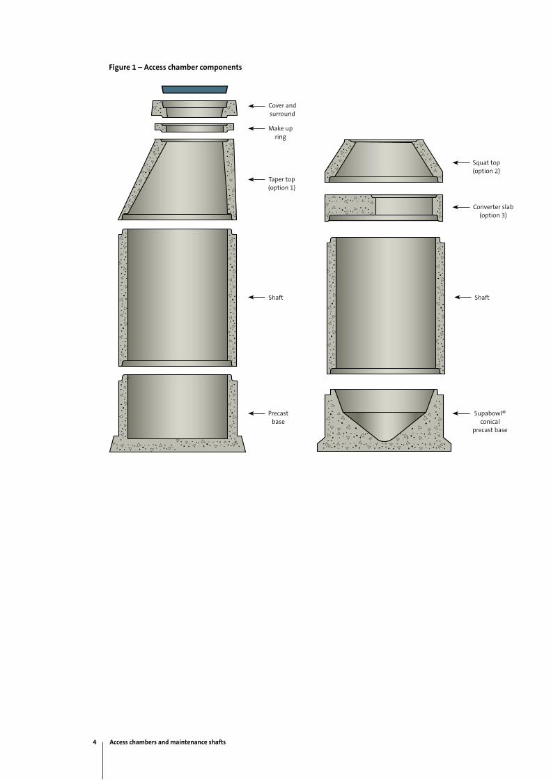
Cover and surround
Make up ring
Taper top(option 1)
Shaft Shaft
Precast base
Figure 1 – Access chamber components
Supabowl® conical
precast base
Squat top(option 2)
Converter slab(option 3)
4 Access chambers and maintenance shafts

Top:The Supabowl® conical precast base
Bottom:HumeSeal® watertight coupling
The Supabowl® conical precast base
The Supabowl® conical precast base has an internal
surface in the shape of an inverted cone. The point of the
cone is semi-spherical and acts as a node where incoming
flows are concentrated prior to draining through a
preformed outlet. Inlets are cored in the factory to suit
site line and levels.
Extensive laboratory testing has shown that this type
of base has the same hydraulic efficiency as traditional
channel benched bases while displaying superior
self-cleansing under surcharge conditions. The unique
design concept eliminates the need for a separate
benching process and greatly improves supply lead times.
HumeSeal® watertight coupling
The HumeSeal® coupling is a mechanical coupling
designed for fast, efficient and watertight joining of
UPVC pipe, DN100 - DN225, into precast concrete
or in-situ structures.
It has been extensively tested and performs well
above specification requirements for pressure, angular
deflection and lateral loads. The HumeSeal® coupling will
accommodate a 90 kPa pressure differential and remain
watertight with up to 17 degrees of angular deflection.
It is constructed to AS 1646 from natural rubber, glass
filled nylon, and 316 stainless steel bolts and nuts, for
compression of the coupling.
Access chambers and maintenance shafts 5
Acc
ess
cham
ber
s
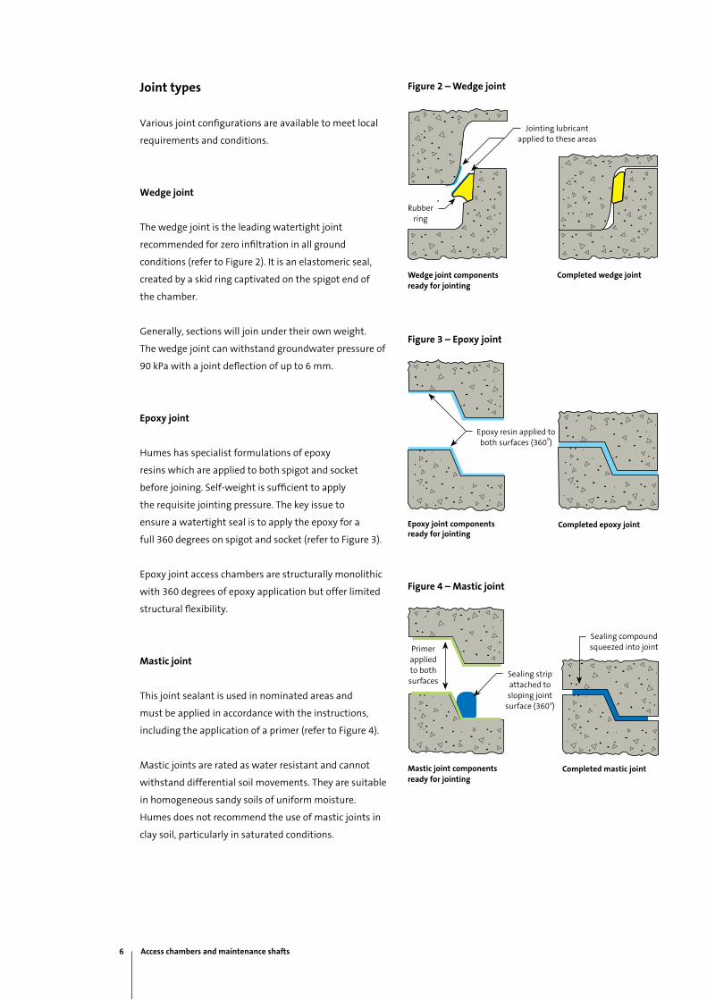
Joint types
Various joint configurations are available to meet local
requirements and conditions.
Wedge joint
The wedge joint is the leading watertight joint
recommended for zero infiltration in all ground
conditions (refer to Figure 2). It is an elastomeric seal,
created by a skid ring captivated on the spigot end of
the chamber.
Generally, sections will join under their own weight.
The wedge joint can withstand groundwater pressure of
90 kPa with a joint deflection of up to 6 mm.
Epoxy joint
Humes has specialist formulations of epoxy
resins which are applied to both spigot and socket
before joining. Self-weight is sufficient to apply
the requisite jointing pressure. The key issue to
ensure a watertight seal is to apply the epoxy for a
full 360 degrees on spigot and socket (refer to Figure 3).
Epoxy joint access chambers are structurally monolithic
with 360 degrees of epoxy application but offer limited
structural flexibility.
Mastic joint
This joint sealant is used in nominated areas and
must be applied in accordance with the instructions,
including the application of a primer (refer to Figure 4).
Mastic joints are rated as water resistant and cannot
withstand differential soil movements. They are suitable
in homogeneous sandy soils of uniform moisture.
Humes does not recommend the use of mastic joints in
clay soil, particularly in saturated conditions.
Figure 2 – Wedge joint
Figure 3 – Epoxy joint
Figure 4 – Mastic joint
Wedge joint components ready for jointing
Completed wedge joint
Jointing lubricant applied to these areas
Rubber ring
Epoxy joint components ready for jointing
Completed epoxy joint
Epoxy resin applied to both surfaces (360
o)
Mastic joint components ready for jointing
Completed mastic joint
Sealing strip attached to sloping joint
surface (360o)
Sealing compound squeezed into jointPrimer
applied to both surfaces
6 Access chambers and maintenance shafts
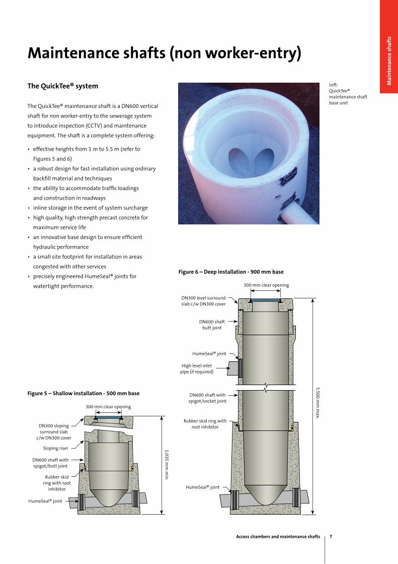
The QuickTee® system
The QuickTee® maintenance shaft is a DN600 vertical
shaft for non worker-entry to the sewerage system
to introduce inspection (CCTV) and maintenance
equipment. The shaft is a complete system offering:
• effective heights from 1 m to 5.5 m (refer to
Figures 5 and 6)
• a robust design for fast installation using ordinary
backfill material and techniques
• the ability to accommodate traffic loadings
and construction in roadways
• inline storage in the event of system surcharge
• high quality, high strength precast concrete for
maximum service life
• an innovative base design to ensure efficient
hydraulic performance
• a small site footprint for installation in areas
congested with other services
• precisely engineered HumeSeal® joints for
watertight performance.
Maintenance shafts (non worker-entry)
Left:QuickTee® maintenance shaft base unit
Figure 5 – Shallow installation - 500 mm base
Figure 6 – Deep installation - 900 mm base
1,035 mm
min
.
300 mm clear opening
DN300 sloping surround slab
c/w DN300 cover
Sloping riser
DN600 shaft with spigot/butt joint
Rubber skid ring with root
inhibitor
HumeSeal® joint
300 mm clear opening
DN300 level surround slab c/w DN300 cover
DN600 shaft butt joint
HumeSeal® joint
High level inlet pipe (if required)
DN600 shaft with spigot/socket joint
Rubber skid ring with root inhibitor
HumeSeal® joint
5,500 mm
max.
Access chambers and maintenance shafts 7
Mai
nte
nan
ce s
haf
ts
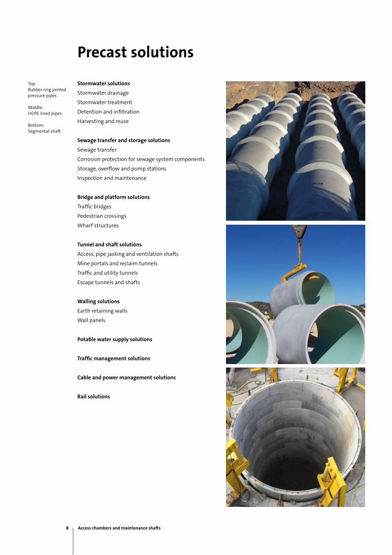
Precast solutions
Stormwater solutions
Stormwater drainage
Stormwater treatment
Detention and infiltration
Harvesting and reuse
Sewage transfer and storage solutions
Sewage transfer
Corrosion protection for sewage system components
Storage, overflow and pump stations
Inspection and maintenance
Bridge and platform solutions
Traffic bridges
Pedestrian crossings
Wharf structures
Tunnel and shaft solutions
Access, pipe jacking and ventilation shafts
Mine portals and reclaim tunnels
Traffic and utility tunnels
Escape tunnels and shafts
Walling solutions
Earth retaining walls
Wall panels
Potable water supply solutions
Traffic management solutions
Cable and power management solutions
Rail solutions
Top:Rubber ring jointed pressure pipes
Middle:HDPE lined pipes
Bottom:Segmental shaft
8 Access chambers and maintenance shafts
National sales 1300 361 601
humes.com.au
Contact information
Melbourne
Ph: (03) 9360 3888
Fax: (03) 9360 3887
Tasmania
Launceston
Ph: (03) 6335 6300
Fax: (03) 6335 6330
South Australia
Adelaide
Ph: (08) 8168 4544
Fax: (08) 8168 4549
Western Australia
Gnangara
Ph: (08) 9302 8000
Fax: (08) 9309 1625
Perth
Ph: (08) 9351 6999
Fax: (08) 9351 6977
Northern Territory
Darwin
Ph: (08) 8984 1600
Fax: (08) 8984 1614
Head Office
18 Little Cribb St
Milton QLD 4064
Ph: (07) 3364 2800
Fax: (07) 3364 2963
Queensland
Brisbane/Gold Coast
Ph: (07) 3866 7100
Fax: (07) 3866 7101
Bundaberg
Ph: (07) 4152 2644
Fax: (07) 4152 5847
Rockhampton
Ph: (07) 4924 7900
Fax: (07) 4924 7901
Sunshine Coast
Ph: (07) 5472 9700
Fax: (07) 5472 9711
Toowoomba
Ph: (07) 4694 1420
Fax: (07) 4634 3874
Townsville
Ph: (07) 4758 6000
Fax: (07) 4758 6001
New South Wales
Canberra
Ph: (02) 6285 5309
Fax: (02) 6285 5334
Grafton
Ph: (02) 6644 7666
Fax: (02) 6644 7313
Kempsey
Ph: (02) 6562 6755
Fax: (02) 6562 4235
Lismore
Ph: (02) 6621 3684
Fax: (02) 6622 1342
Newcastle
Ph: (02) 4032 6800
Fax: (02) 4032 6822
Sydney
Ph: (02) 9832 5555
Fax: (02) 9625 5200
Tamworth
Ph: (02) 6763 7300
Fax: (02) 6763 7301
Victoria
Echuca
Ph: (03) 5480 2371
Fax: (03) 5482 3090

This brochure supersedes all previous literature on this subject. As the specifications and details contained in this publication may change please check with Humes Customer Service for confirmation of current issue. This document is provided for information only. Users are advised to make their own determination as to the suitability of this information for their own specific circumstances. We accept no responsibility for any loss or damage resulting from any person acting on this information. Humes is a registered trademark and a registered business name of Holcim (Australia) Pty Ltd. HumeSeal, Supabowl and QuickTee are registered trademarks of Holcim (Australia) Pty Ltd. © July 2012 Holcim (Australia) Pty Ltd ABN 87 099 732 297
National sales 1300 361 601
humes.com.au
A Division of Holcim Australia