accepted manuscript - centralesupelecpublilgep.geeps.centralesupelec.fr/papers/001732.pdf ·...
TRANSCRIPT

Accepted Manuscript
A dynamic router for microgrid applications:
Theory and experimental results
Victor Ramirez, Romeo Ortega, Olivier Bethoux, Antonio Sánchez‐Squella
DOI: 10.1016/j.conengprac.2014.02.005
Reference:
Publisher: ELSEVIER
To appear in: Control Engineering Practice
Received date: 25 February2013
Accepted date: 5 February2014
Date of Publication: 13 March2014 (on line)
Please cite this article as: Victor Ramirez, Romeo Ortega, Olivier Bethoux, Antonio Sánchez‐
Squella, A dynamic router for microgrid applications: Theory and experimental results, Control
Engineering Practice, Volume 27, May 2014, Pages 23‐31, ISSN 0967‐0661,
http://dx.doi.org/10.1016/j.conengprac.2014.02.005.
doi: 10.1016/j.conengprac.2014.02.005
Document Version: Early version, also known as pre‐print
This is a PDF file of an unedited manuscript that has been accepted for publication. As a service
to our customers we are providing this early version of the manuscript. The manuscript will
undergo copyediting, typesetting, and review of the resulting proof before it is published in
its final form. Please note that during the production process errors may be discovered which
could affect the content, and all legal disclaimers that apply to the journal pertain.

A dynamic router for microgrid applications:Theory and experimental results
Victor Ramirez a,n, Romeo Ortega a, Olivier Bethoux b, Antonio Sánchez-Squella c
a Laboratoire des Signaux et Systémes, Supélec – 3 rue Joliot Curie, Plateau de Moulon, 91192 Gif-sur-Yvette, Franceb LGEP – CNRS/SUPELEC, 11 rue Joliot Curie, Plateau de Moulon, 91192 Gif sur Yvette, Francec Departamento de Ingeniería Eléctrica, Universidad Técnica Federico Santa María, Avda. Vicuña Mackema 3939, San Joaquín, Santiago, Chile
a r t i c l e i n f o
Article history:Received 25 February 2013Accepted 5 February 2014Available online 13 March 2014
Keywords:Nonlinear controlPower electronicsPassive systemsEnergy managementMicrogrids
a b s t r a c t
Efficient regulation of the energy transfer between generating, storage and load subsystems is a topic ofcurrent practical interest. A new strategy to achieve this objective, together with its corresponding powerelectronics implementation, was recently proposed by the authors. The device is called dynamic energyrouter (DER) because, in contrast with current practice, the regulation of the direction and rate of changeof the power flow is done without relying on steady-state considerations. In this paper it is shown that,unfortunately, the DER becomes non-operational in the (unavoidable) presence of losses in the system.Hence, we propose a new DER that overcomes this problem. Experimental evidence of the performanceof the original and new DER is presented.
& 2014 Elsevier Ltd. All rights reserved.
1. Introduction
Achieving efficient transfer of electric energy between multi-domain subsystems that can generate, store, or consume energy isa central problem in modern microgrid systems (Fraghani, 2010).As an example consider the case of a hybrid vehicle containing fuelcells, supercapacitors, battery and electric motors. Depending onthe operation regime (in the example, essentially determinedby fuel consumption considerations), energy must be transferredbetween the various units—that, in the sequel will be refer to asmultiports—according to some energy-management policies. Theenergy exchange between the multiports is achieved interconnect-ing them through power converters, which are electronicallyswitched circuits capable of adjusting the magnitudes of the portvariables, voltage or current, to a desired value.
To achieve the desired energy-management policy, it is acommon practice to assume that the system operates in steadystate and then translates the power demand (flow sense andmagnitude) for each multiport into current or voltage references—see, e.g., Malo and Griñó (2007), Thounthong, Raël, and Davat(2005), Choi, Howze, and Enjeti (2006) and Schenck, Lai, andStanton (2005). These references are then tracked with controlloops, usually proportional plus integral (PI). Since the variousmultiports have different time responses, it is often necessary to
discriminate between quickly and slowly changing power demandprofiles. For instance, due to physical constraints, it is not desirableto demand quickly changing power profiles to a fuel cell unit.Hence, the peak demands of the motors are usually supplied bythe supercapacitors, whose time response is fast. To achieve thisobjective, a steady-state viewpoint is again adopted, and thecurrent or voltage references to the multiports are passed eitherthrough low-pass or high-pass linear time-invariant (LTI) filters.
The steady-state approach currently adopted in practice canonly approximately fulfill the desired objectives of energy transferand slow-versus-fast discrimination of the power demand. Inparticular, during the transients or when fast dynamic responseis required, the delivery of demanded power in response tocurrent or voltage references and the time response action of thefilters might be far from satisfactory.
Following the principles of control-by-interconnection (Ortega& van der Schaft, 2008) a new strategy to dynamically control theenergy flow between lossless multiports, together with its corre-sponding power electronics implementation with standard circuittopologies was proposed in Sánchez-Squella, Ortega, Griñó, andMalo (2010). The device was called Duindam–Stramigioli DynamicEnergy Router (DS-DER) because, on one hand, it is inspired by theconceptual energy discrimination idea proposed in the context ofwalking robots in Duindam and Stramigioli (2004). While, onthe other hand, in contrast to current practice, it does not rely onsteady-state considerations. The DS-DER generates, via a nonlineartransformation, the references (voltages or currents) of all multi-ports that, under the assumptions of perfect tracking, ensuresinstantaneous energy transfer among multiports.
Contents lists available at ScienceDirect
journal homepage: www.elsevier.com/locate/conengprac
Control Engineering Practice
http://dx.doi.org/10.1016/j.conengprac.2014.02.0050967-0661 & 2014 Elsevier Ltd. All rights reserved.
n Corresponding authorE-mail addresses: [email protected] (V. Ramirez),
[email protected] (R. Ortega), [email protected] (O. Bethoux),[email protected] (A. Sánchez-Squella).
Control Engineering Practice 27 (2014) 23–31

As explained in Sánchez-Squella et al. (2010), the flow directionand rate of change of the energy transfer are regulated by meansof some free parameters, which in the simplest two multiport casereduces to a single scalar function of time. The selection of theseparameters is rather intuitive, and replaces the time-consumingtask of selecting the LTI filters that (approximately) enforce thedesired time scale separation between the multiports. Anotherfeature that distinguishes the DS-DER with current practice is that,since the references of all interconnected multiports are generatedin a centralized manner, information exchange among them isrequired, which is the operating scenario in some modern energytransfer applications, e.g., in microgrids.
A key assumption for the correct operation of the DS-DERproposed in Sánchez-Squella et al. (2010) is that both, the multiportsand the DER itself, are ideal lossless devices. Unfortunately, in thispaper it is shown that in the presence of dissipation—which is,obviously, unavoidable in applications—the energy of the DERmonotonically decreases leading to an improper behavior, andeventually total dysfunction, of the DS-DER. There are three objec-tives of this paper:
(1) Propose a modified DER that overcomes this fundamentalproblem, with guaranteed stability properties.
(2) To show that adding to the DS-DER an external energy sourceto compensate for the losses and an outer-loop PI providesexcellent experimental results. As usual with simple engineer-ing intuition-based control schemes, no theoretical basis forthe performance improvement of this DER can be provided.
(3) Compare via experiments the performances of the DS-DER, thenew DER and the DS-DER plus battery configuration.
The paper is organized as follows. In Section 2, the energy-management problem is formulated, and the classical procedureused for its solution is reviewed. In Section 3 we briefly review theDS-DER reported in Sánchez-Squella et al. (2010) and reveal itslimitation in the presence of dissipation. Section 4 contains thenew DER that overcomes this obstacle. Experimental resultsfor the DS-DER and the new DER are presented in Sections5 and 6, respectively. In Section 7 we present two ad hocmodifications to the DS-DER that were proposed to render itoperative in spite of the presence of dissipation, the experimentalevaluation of their performance is also given in that section. Thepaper ends with some concluding remarks and future research inSection 8.
2. Formulation of the energy transfer problem
In this section the mathematical formulation of the problem isgiven. We consider a system composed of N multiports intercon-nected, via (switch-regulated) power converters, to exchange energyaccording to a pre-specified energy-management policy.
2.1. The multiports
It is assumed that the multiports, denoted by Σj, jAN≔f1;…;Ng,have as port variables the terminal voltages and currents, which wedenote as vjðtÞ; ijðtÞARmj , respectively, see Fig. 1. It is also assumedthat the multiports satisfy the energy-conservation law:
Stored Energy¼ Supplied Energy�Dissipated Energy:
The following scenario is considered.
(i) The stored energy is represented by a scalar function~Hj : R
nj-R, whose argument xjðtÞARnj is the state vector ofthe multiport. In an electrical circuit, xj(t) consists of electriccharges in the capacitors and magnetic fluxes in the inductors.
(ii) The power delivered by, or demanded from, the external environ-ment is defined as
PjðtÞ ¼ v>j ðtÞijðtÞ; ð1Þ
with energy given by its integral.(iii) The dissipated power is a non-negative function denoted as
dj : Rþ-Rþ . For instance, the power dissipated in a linearresistive element R is given by
dðtÞ ¼ Ri2RðtÞ;where R40 is the value of the resistor and iR(t) is the currentflowing through it.
With this notation the energy-conservation law, in power form,becomes
_HjðtÞ ¼ PjðtÞ�djðtÞ; ð2Þwhere HjðtÞ≔ ~HjðxjðtÞÞ. Integrating (2), and using (1), yields
HjðtÞ�Hjð0Þ ¼Z t
0v>j ðsÞijðsÞ ds�
Z t
0djðsÞ ds:
Since djðtÞZ0, we have
HjðtÞ�Hjð0ÞrZ t
0v>j ðsÞijðsÞ ds; ð3Þ
reflecting the fact that the energy stored in the system cannotexceed the energy supplied from the environment, the differencebeing the dissipation.
Notice that, in order to be able to treat multiports with sources,we have not assumed that the energy function is positive definite—or bounded from below. For instance, the dynamics of an idealbattery is given by
_xbðtÞ ¼ ibðtÞvbðtÞ ¼ ~H
0bðxÞ;
where ð�Þ0 denotes differentiation, and
~HbðxbÞ ¼ Vbxb
is the (unbounded) energy, with VbARþ the voltage of thebattery. Clearly
HbðtÞ ¼ Vb
Z t
0ibðsÞ ds;
which is the energy extracted from the battery.If the energy function ~HðxÞ is positive definite, from (3) we
obtain
�Z t
0v>j ðsÞijðsÞ dsrHjð0Þ;
stating that the energy extracted from the multiport is bounded(by the initial energy), which is the usual characterization ofpassive systems (Ortega, Loria, Nicklasson, & Sira-Ramirez, 1998).
Fig. 1. Representation of a subsystem, such as fuel cell or battery, as a multiport,denoted by Σj, with port variables vj(t) and ij(t).
V. Ramirez et al. / Control Engineering Practice 27 (2014) 23–3124

2.2. Standard energy management procedure
The typical procedure to achieve the energy transfer is as follows(Choi et al., 2006; Malo & Griñó, 2007; Schenck et al., 2005;Thounthong et al., 2005). Assume that at a given time t0Z0 ademand P⋆
j of power is requested from multiport Σj. Measuring thevoltage vjðt0Þ, the power demand is then transformed into a constantcurrent reference i⋆j , solving the instantaneous power relation:
P⋆j ¼ v>
j ðt0Þi⋆j : ð4Þ
This current reference is imposed to the controller regulating theswitches of the corresponding power converter, usually a PI loop, todrive to zero the current error ijðtÞ� i⋆j . In this way, the desiredenergy-transfer objective is achieved asymptotically—provided thepresumed steady-state behavior did not change.
The following observations regarding the aforementioned strategyare in order. First, regulation towards the desired current value i⋆j is,of course, not instantaneous, and during the transient the voltagevj(t) will change. Consequently, the actual power extracted (orsupplied) to the multiport Σj will, in general, not coincide with P⋆
j .Second, the strategy is intrinsically decentralized and neglects theloading effects that appear due to the interconnection of the multi-ports. To partially overcome this drawback, a second supervisory levelcontrol is added to achieve the coordination between the multiportspower demands—whose successful operation relies on time-scaleseparation assumptions that are, partially, enforced via filtering. Bothshortcomings are, to a certain point, palliated by the DER.
3. The Duindam–Stramigioli DER
In this section we briefly review the DS-DER of Sánchez-Squellaet al. (2010) and show its limitation in the presence of dissipation.
3.1. The interconnection system
In the DER the various power converters interconnecting themultiports are grouped together. It then defines a dynamicalsystem with state ξARnI , energy function ~HI : R
nI-Rþ and N portvariables vIjðtÞ; iIjðtÞARmj that, being a physical system, also satis-fies the energy conservation law
_HIðtÞ ¼ ∑N
j ¼ 1v>Ij ðtÞiIjðtÞ�dIðtÞ; ð5Þ
where HIðtÞ≔ ~HIðξðtÞÞ and dI : Rþ-Rþ is the dissipation.The multiports and the power converter device are coupled via
the power-preserving interconnection:
ijðtÞvjðtÞ
" #¼
0 � Imj
Imj 0
" #vIjðtÞiIjðtÞ
" #: ð6Þ
See Fig. 2. Defining the energy of the overall system
HT ðtÞ ¼ ∑N
j ¼ 1HjðtÞþHIðtÞ;
yields the power balance
_HT ðtÞ ¼ �dIðtÞ� ∑N
j ¼ 1djðtÞ:
3.2. The dissipation obstacle of the DS-DER
The basic assumption of the DS-DER proposed in Sánchez-Squella et al. (2010) is that the energy dissipated in the multiportsand the interconnection system is negligible, that is,
dIðtÞ; djðtÞ � 0:
In this case, the power balance of each multiport becomes
_HjðtÞ ¼ v>j ðtÞijðtÞ: ð7Þ
Consider, for simplicity, the case of two lossless multiports.Assume that at time tZ0 it is desired to instantaneously transferenergy from multiport Σ1 to multiport Σ2. That is, to make
_H1ðtÞ40; _H2ðtÞo0: ð8ÞThe DS-DER of Sánchez-Squella et al. (2010) generates the currentreferences i⋆j ðtÞ for bothmultiports to ensure (8), and is defined by1
i⋆1i⋆2
" #¼
0 αðtÞv1ðtÞv>2 ðtÞ
�αðtÞv2ðtÞv>1 ðtÞ 0
" #v1ðtÞv2ðtÞ
" #; ð9Þ
where α : Rþ-R is a designer-chosen function. Substituting thecurrent expressions of (9) into (7), and setting ijðtÞ ¼ i⋆j ðtÞ, yields_H1ðtÞ ¼ αðtÞjv1ðtÞj2jv2ðtÞj2_H2ðtÞ ¼ �αðtÞjv1ðtÞj2jv2ðtÞj2: ð10Þ
Clearly, if αðtÞ40, then (8) is satisfied. The energy direction can beinverted setting αðtÞo0, when energy flows from Σ2 to Σ1. There-fore, as shown in Sánchez-Squella et al. (2010), αðtÞ controls thedirection and rate of change of the energy flow, obviating the needof the LTI filters used in standard practice.
Unfortunately, in the presence of dissipation the performanceof the DS-DER (9) is asymptotically degraded and, eventually,ceases to be functional. Indeed, because of the skew-symmetry ofthe matrix in the right hand side of (9), multiplying (9) on the leftby the row vector ½v>
1 ðtÞ v>2 ðtÞ�, and setting ijðtÞ ¼ i⋆j ðtÞ, yields
v>1 ðtÞi1ðtÞþv>
2 ðtÞi2ðtÞ ¼ 0: ð11Þ
Replacing (11) in (5), and using (6), leads to
_HIðtÞ ¼ �dIðtÞ; ð12Þconsequently, after convergence of the current tracking errors,the energy of the DS-DER monotonically decreases, leading to animproper behavior.
4. A new DER with losses compensation
To overcome the limitation mentioned in the previous sectionwe propose to design the DER taking into account the presence ofthe dissipation in the interconnection subsystem dI(t), which weassume is measurable. Notice that, since the DER is composed ofthe power converters, a good estimate of the resistive elements isavailable.2
Fig. 2. Overall interconnected system for N¼3.
1 The DER (9) is meant for current-tracking applications. See Sánchez-Squellaet al. (2010) for a voltage-tracking version.
2 It should be underscored, however, that there are losses in power convertersstemming from the switching devices that are hard to estimate.
V. Ramirez et al. / Control Engineering Practice 27 (2014) 23–31 25
To streamline the problem formulation we define N mappingsFj : Rr-Rmj , where r≔∑N
j ¼ 1mj, and the vectors
v≔colðv1;…; vNÞ; FðvÞ≔colðF1ðvÞ;…; FNðvÞÞ:The mappings Fj(v) define the current references as
i⋆j ðtÞ ¼ FjðvðtÞÞ; jAN ;
and they should meet two different objectives. First, to ensure thedesired power dispatch, they should satisfy
P⋆j ðtÞ ¼ v>
j ðtÞFjðvðtÞÞ;where P⋆
j : Rþ-R is the power that we want to extract (orprovide) to the j-th multiport—this information comes from ahigher level energy dispatch system. Second, to compensate forthe dissipation in the DER, the mappings should satisfy
∑N
j ¼ 1v>j ðtÞFjðvðtÞÞ ¼ dIðtÞ: ð13Þ
Indeed, from (5) and (6), it is clear that if ijðtÞ-i⋆j ðtÞ, then theenergy of the DER is regulated at a constant value, i.e., _HIðtÞ-0—avoiding the discharge phenomenon of the DS-DER.
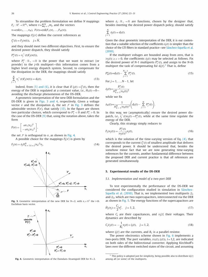
A geometric interpretation of the new DER formulation and theDS-DER is given in Figs. 3 and 4, respectively. Given a voltagevector v and the dissipation dI, the set F in Fig. 3 defines theadmissible vectors F(v), that satisfy (13). In the figure are showntwo particular choices, which correspond to P⋆
1 o0 and P⋆1 40. In
the case of the DS-DER (9) that, using the notation above, takes theform
FðvÞ ¼ αv1jv2j2�αv2jv1j2
" #;
the set F is orthogonal to v, as shown in Fig. 4.A possible choice for the mappings Fj(v) is given by
FjðvÞ ¼ δjΠNk ¼ 1;ka jjvkj2vj; ð14Þ
where δj : Rþ-R are functions, chosen by the designer that,besides meeting the desired power dispatch policy, should satisfy
∑N
j ¼ 1δjðtÞ ¼ dIðtÞ:
Given the clear geometric interpretation of the DER, it is our conten-tion that a suitable selection of the coefficients δjðtÞ is simpler than thechoice of the LTI filters in standard practice—see Sánchez-Squella et al.(2010).
If the multiport voltages are bounded away from zero, that isjvjðtÞjZϵ40, the coefficients δjðtÞ may be selected as follows. Fixthe desired power of N-1 multiports P⋆
j ðtÞ, and assign to the N-thmultiport the task of compensating for dI(t).3 That is, define
P⋆NðtÞ≔dIðtÞ� ∑
N�1
j ¼ 1P⋆j ðtÞ: ð15Þ
For j¼ 1;…;N�1, let
δjðtÞ≔P⋆j ðtÞ
ΠNk ¼ 1jvkðtÞj2
while we fix
δNðtÞ≔1
ΠNk ¼ 1jvkðtÞj2
dIðtÞ� ∑N
j ¼ 1P⋆j ðtÞ
!:
In this way, we (asymptotically) ensure the desired power dis-patch, i.e., i>j ðtÞvjðtÞ-P⋆
j ðtÞ, while at the same time regulate theenergy of the DER.
Clearly, this strategy simply reduces to
FjðvjðtÞÞ ¼P⋆j ðtÞ
jvjðtÞj2vjðtÞ; ð16Þ
which is the solution of the time-varying version of Eq. (4), thatcorresponds to the current i⋆j ðtÞ of smallest amplitude that deliversthe desired power. It should be underscored that, besides thesomehow minor fact that we are now generating time-varyingreferences for the currents, another fundamental difference betweenthe proposed DER and current practice is that all references aregenerated simultaneously.
5. Experimental results of the DS-DER
5.1. Implementation and model of a two-port DER
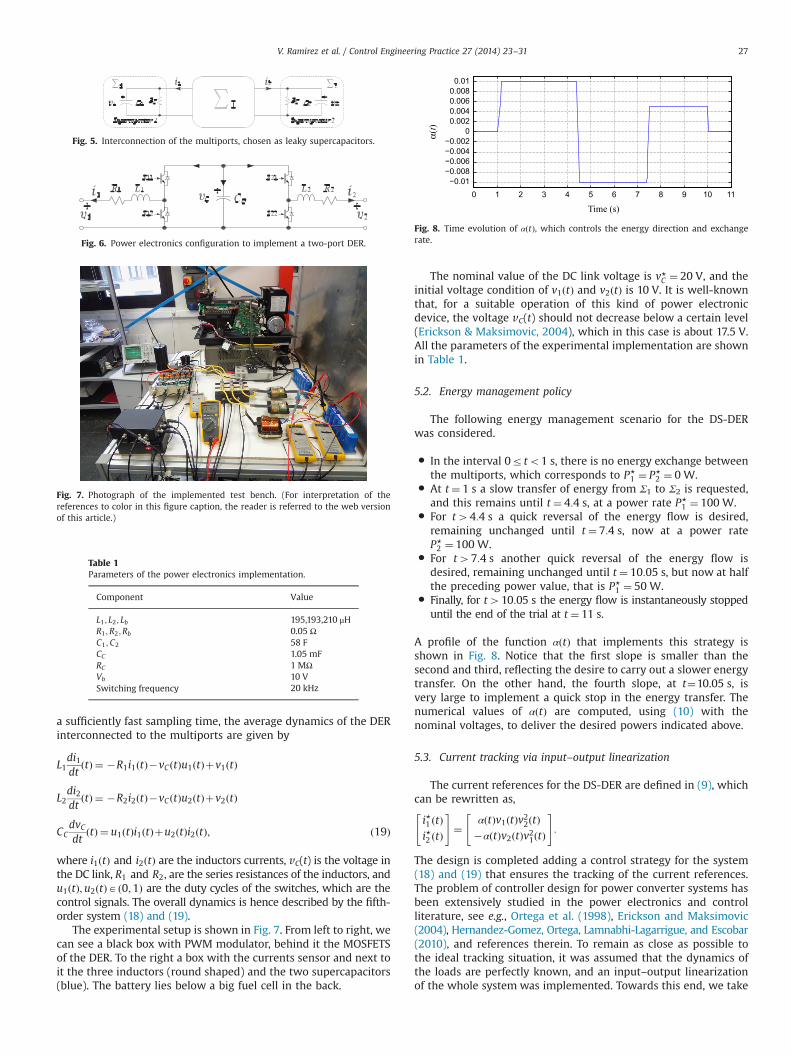
To test experimentally the performance of the DS-DER weconsidered the configuration studied in simulation in Sánchez-Squella et al. (2010). That is, we implemented two multiports Σ1
and Σ2, which are two supercapacitors, interconnected via the DERas shown in Fig. 5. The energy functions of the supercapacitors are
~HjðvjÞ ¼Cj
2v2j ; j¼ 1;2; ð17Þ
where Cj are their capacitances, and vj(t) their voltages. Theirdynamics are described by
Cj _vjðtÞ ¼ � 1RC
vjðtÞþ ijðtÞ; j¼ 1;2; ð18Þ
where ij(t) are the currents, and RC is a parallel resistor.The power electronics scheme shown in Fig. 6 implements a
two-ports DER. The port variables, ðviðtÞ; iiðtÞÞ; i¼1,2, are indicatedon both sides of the bidirectional converter. Applying Kirchhoff'slaws over the different switched states of the circuit, and assuming
Fig. 3. Geometric interpretation of the new DER for N¼2, with eiAR2 the i-thEuclidean basis vector.
Fig. 4. Geometric interpretation of the Duindam–Stramigioli DER for N¼2.
3 This policy is adopted just for simplicity, being possible also to distribute dI(t)among all (or some) of the multiports.
V. Ramirez et al. / Control Engineering Practice 27 (2014) 23–3126
a sufficiently fast sampling time, the average dynamics of the DERinterconnected to the multiports are given by
L1di1dt
ðtÞ ¼ �R1i1ðtÞ�vCðtÞu1ðtÞþv1ðtÞ
L2di2dt
ðtÞ ¼ �R2i2ðtÞ�vCðtÞu2ðtÞþv2ðtÞ
CCdvCdt
ðtÞ ¼ u1ðtÞi1ðtÞþu2ðtÞi2ðtÞ; ð19Þ
where i1ðtÞ and i2ðtÞ are the inductors currents, vC(t) is the voltage inthe DC link, R1 and R2, are the series resistances of the inductors, andu1ðtÞ;u2ðtÞAð0;1Þ are the duty cycles of the switches, which are thecontrol signals. The overall dynamics is hence described by the fifth-order system (18) and (19).
The experimental setup is shown in Fig. 7. From left to right, wecan see a black box with PWM modulator, behind it the MOSFETSof the DER. To the right a box with the currents sensor and next toit the three inductors (round shaped) and the two supercapacitors(blue). The battery lies below a big fuel cell in the back.
The nominal value of the DC link voltage is v⋆C ¼ 20 V, and theinitial voltage condition of v1ðtÞ and v2ðtÞ is 10 V. It is well-knownthat, for a suitable operation of this kind of power electronicdevice, the voltage vC(t) should not decrease below a certain level(Erickson & Maksimovic, 2004), which in this case is about 17.5 V.All the parameters of the experimental implementation are shownin Table 1.
5.2. Energy management policy
The following energy management scenario for the DS-DERwas considered.
� In the interval 0rto1 s, there is no energy exchange betweenthe multiports, which corresponds to P⋆
1 ¼ P⋆2 ¼ 0 W.
� At t ¼ 1 s a slow transfer of energy from Σ1 to Σ2 is requested,and this remains until t ¼ 4:4 s, at a power rate P⋆
1 ¼ 100 W.� For t44:4 s a quick reversal of the energy flow is desired,
remaining unchanged until t ¼ 7:4 s, now at a power rateP⋆2 ¼ 100 W.
� For t47:4 s another quick reversal of the energy flow isdesired, remaining unchanged until t ¼ 10:05 s, but now at halfthe preceding power value, that is P⋆
1 ¼ 50 W.� Finally, for t410:05 s the energy flow is instantaneously stopped
until the end of the trial at t ¼ 11 s.
A profile of the function αðtÞ that implements this strategy isshown in Fig. 8. Notice that the first slope is smaller than thesecond and third, reflecting the desire to carry out a slower energytransfer. On the other hand, the fourth slope, at t¼10.05 s, isvery large to implement a quick stop in the energy transfer. Thenumerical values of αðtÞ are computed, using (10) with thenominal voltages, to deliver the desired powers indicated above.
5.3. Current tracking via input–output linearization
The current references for the DS-DER are defined in (9), whichcan be rewritten as,
i⋆1 ðtÞi⋆2 ðtÞ
" #¼
αðtÞv1ðtÞv22ðtÞ�αðtÞv2ðtÞv21ðtÞ
" #:
The design is completed adding a control strategy for the system(18) and (19) that ensures the tracking of the current references.The problem of controller design for power converter systems hasbeen extensively studied in the power electronics and controlliterature, see e.g., Ortega et al. (1998), Erickson and Maksimovic(2004), Hernandez-Gomez, Ortega, Lamnabhi-Lagarrigue, and Escobar(2010), and references therein. To remain as close as possible tothe ideal tracking situation, it was assumed that the dynamics ofthe loads are perfectly known, and an input–output linearizationof the whole system was implemented. Towards this end, we take
Fig. 5. Interconnection of the multiports, chosen as leaky supercapacitors.
Fig. 6. Power electronics configuration to implement a two-port DER.
Fig. 7. Photograph of the implemented test bench. (For interpretation of thereferences to color in this figure caption, the reader is referred to the web versionof this article.)
Table 1Parameters of the power electronics implementation.
Component Value
L1 ; L2 ; Lb 195,193,210 μHR1 ;R2 ;Rb 0.05 ΩC1 ;C2 58 FCC 1.05 mFRC 1 MΩVb 10 VSwitching frequency 20 kHz
0 1 2 3 4 5 6 7 8 9 10 11−0.01−0.008−0.006−0.004−0.002
00.0020.0040.0060.0080.01
α(t)
Time (s)
Fig. 8. Time evolution of αðtÞ, which controls the energy direction and exchangerate.
V. Ramirez et al. / Control Engineering Practice 27 (2014) 23–31 27

as system outputs the tracking errors
~i1ðtÞ ¼ i1ðtÞ�αv1ðtÞv22ðtÞ~i2ðtÞ ¼ i2ðtÞþαv21ðtÞv2ðtÞ; ð20Þ
that we want to drive to zero. Some simple calculations show thatthe system (18) and (19), with outputs (20) and inputs u1ðtÞ;u2ðtÞ,has a well-defined relative degree ð1;1Þ and can be input–outputlinearized with the control law
u1 ¼L1vC
�R1i1þv1L1
þαv22C1
i1þv1RC1
� �� �
þL1vC
2αv1v2C2
i2þv2RC2
� ��w1
� �
u2 ¼L2vC
�R2i2þv2L2
�αv21C2
i2þv2RC2
� �� �
�L2vC
2αv1v2C1
i1þv1RC1
� ��w2
� �; ð21Þ
where, w1ðtÞ;w2ðtÞ are the new input signals. That is, the closed-loop system takes the simple linear form
d~ijdt
ðtÞ ¼wjðtÞ; j¼ 1;2:
To complete the design the new inputs wj(t) are taken as PIcontrollers around ~ijðtÞ, that is,
wjðtÞ ¼ �kpj~ijðtÞ�kij
Z t
0
~ijðsÞ ds; j¼ 1;2; ð22Þ
with kpj ; kij some positive tuning gains. This yields the exponen-tially stable dynamics
d2~ijdt2
ðtÞþkpjd~ijdt
ðtÞþkij~ijðtÞ ¼ 0; j¼ 1;2:
5.4. Effect of dissipation on the DS-DER
The transient performance of the DS-DER with the input–output feedback linearizing controller (20)–(22) is depicted inFig. 9. As seen from the figure the current tracking errors are keptsmall, the power transfer is done in the desired direction andrequested rate of change. Moreover, the DC link voltage vC(t) iskept within reasonable values. However, we observe that since thepower dissipated in the DER is not compensated, the values of thecapacitors powers tend to decrease with time.
The power loss trend is more clearly seen in Fig. 10, whichcorresponds to a much longer experimentation time. Notice thatthe current tracking errors are still kept small,4 however the DC
0 1 2 3 4 5 6 7 8 9 10
−100−80−60−40−20020406080100
Pow
er (W
)
Time (s)
0 1 2 3 4 5 6 7 8 9 10
−1.5
−1
−0.5
0
0.5
1
Erro
r (A
)
Time (s)
0 1 2 3 4 5 6 7 8 9 1017
17.518
18.519
19.520
20.521
21.5
Volta
ge (V
)
Time (s)
Fig. 9. Experimental results of the DS-DER (30)–(32) in a short time window: (a)P1ðtÞ; P2ðtÞ; (b) ~i1ðtÞ; ~i2ðtÞ; (c) vC(t).
0 100 200 300 400 500 600 700 800 900 1000−100−80−60−40−20020406080100
Pow
er (W
)
Time (s)
0 100 200 300 400 500 600 700 800 900 1000−2
−1.5
−1
−0.5
0
0.5
1
1.5
Erro
r (A
)
Time (s)
0 100 200 300 400 500 600 700 800 900 10001011121314151617181920
Volta
ge (V
)
Time (s)
Fig. 10. Experimental results of the DS-DER (30)–(32) in a long time window: (a)P1ðtÞ; P2ðtÞ; (b) ~i1ðtÞ; ~i2ðtÞ; (c) vC(t).
4 Actually, a similar behavior was observed for other current tracking con-trollers, e.g., PI-based.
V. Ramirez et al. / Control Engineering Practice 27 (2014) 23–3128
link voltage decreases to a level where the device ceases to beoperational. This deleterious behavior was not observed in thesimulations of Sánchez-Squella et al. (2010) were a larger capacitorwas used in the DC link, whose discharge time was much largerthan the considered time horizon.
6. Experimental results for the new DER
In this section the new DER proposed in Section 4 is tried inexperiments. To compensate for the losses in the DER we add athird multiport that consists of a simple battery, whose control isfixed by the energy management policy described in Section 4.
6.1. Implementation and model of a three-port DER
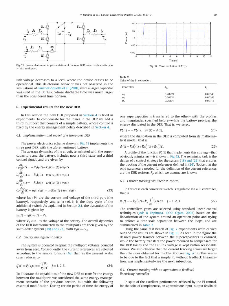
The power electronics scheme shown in Fig. 11 implements thethree port DER with the aforementioned battery.
The average dynamics of the circuit, terminated with the super-capacitors and the battery, includes now a third state and a thirdcontrol signal, and are given by
L1di1dt
ðtÞ ¼ �R1i1ðtÞ�vCðtÞu1ðtÞþv1ðtÞ
L2di2dt
ðtÞ ¼ �R2i2ðtÞ�vCðtÞu2ðtÞþv2ðtÞ
Lbdi3dt
ðtÞ ¼ �Rbi3ðtÞ�vCðtÞu3ðtÞþv3ðtÞ
CCdvCdt
ðtÞ ¼ u1ðtÞi1ðtÞþu2ðtÞi2ðtÞþu3ðtÞi3ðtÞ; ð23Þ
where i3ðtÞ;V3 are the current and voltage of the third port (thebattery), respectively, and u3ðtÞAð0;1Þ is the duty cycle of theadditional switch. As explained in Section 2.1, the dynamics of thebattery is given by
_x3ðtÞ ¼ i3ðtÞv3ðtÞ ¼ Vb;
where VbARþ is the voltage of the battery. The overall dynamicsof the DER interconnected to the multiports are then given by thesixth-order system (18) and (23), with v3ðtÞ ¼ Vb.
6.2. Energy management policy
The system is operated keeping the multiport voltages boundedaway from zero. Consequently, the current references are selectedaccording to the simple formula (16) that, in the present scalarcase, reduces to
i⋆j ðtÞ ¼ FjðvjðtÞÞ ¼P⋆j ðtÞvjðtÞ
; j¼ 1;2;3: ð24Þ
To illustrate the capabilities of the new DER to transfer the energybetween the multiports we considered the same energy manage-ment scenario of the previous section, but with the followingessential modification. During certain period of time the energy of
one supercapacitor is transferred to the other—with the profilesand magnitudes specified before—while the battery provides theenergy dissipated in the DER. That is, we select
P⋆1 ðtÞ ¼ �P⋆
2 ðtÞ; P⋆3 ðtÞ ¼ dIðtÞ; ð25Þ
where the dissipation in the DER is computed from its mathema-tical model, that is,
dIðtÞ ¼ R1i21ðtÞþR2i
22ðtÞþR3i
23ðtÞ: ð26Þ
A profile of the function P⋆1 ðtÞ that implements this strategy—that
obviously mimics αðtÞ—is shown in Fig. 12. The remaining task is thedesign of a control strategy for the system (18) and (23) that ensuresthe tracking of the current references defined in (24). Notice that theonly parameters needed for the definition of the current referencesare the DER resistors Rj, which we assume are known.
6.3. Current tracking via linear PI control
In this case each converter switch is regulated via a PI controller,that is
ujðtÞ ¼ �kpj~ijðtÞ�kij
Z t
0
~ijðsÞ ds; j¼ 1;2;3: ð27Þ
The controllers gains are selected using standard linear controltechniques (Joós & Espinoza, 1999; Ogata, 2003) based on thelinearization of the system around an operation point and tryingto enforce a time-scale separation between the loops, and aresummarized in Table 2.
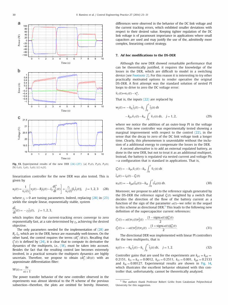
Using the same test bench of Fig. 7 experiments were carriedout and the results are shown in Fig. 13. As seen in the figure thedesired power transfer between the supercapacitors is ensured,while the battery transfers the power required to compensate forthe DER losses and the DC link voltage is kept within reasonablevalues. We also observe that the current tracking errors are largerthan the ones obtained for the DS-DER (see Fig. 9(b).) This seemsto be due to the fact that a simple PI, without feedback lineariza-tion, was implemented—see the next subsection.
6.4. Current tracking with an approximate feedbacklinearizing controller
In spite of the excellent performance achieved by the PI control,for the sake of completeness, an approximate input–output feedback
Fig. 11. Power electronics implementation of the new DER router with a battery asa third multiport.
0 1 2 3 4 5 6 7 8 9 10 11−100
−50
0
50
100
Pow
er (W
)
Time (s)
Fig. 12. Time evolution of P⋆1 ðtÞ.
Table 2Gains of the PI controllers.
Controller kpj kij
u1 0.20224 0.00143u2 0.20224 0.00143u3 0.25101 0.00112
V. Ramirez et al. / Control Engineering Practice 27 (2014) 23–31 29
linearization controller for the new DER was also tested. This isgiven by
ujðtÞ ¼1
vCðtÞvjðtÞ�RjijðtÞ�Lj
di⋆jdt
ðtÞ" #
þ γjvCðtÞ
½Lj~ijðtÞ�; j¼ 1;2;3 ð28Þ
where γj40 are tuning parameters. Indeed, replacing (28) in (23)yields the simple linear, exponentially stable, system
d~ijdt
ðtÞ ¼ �γj~ijðtÞ; j¼ 1;2;3;
which implies that the current-tracking errors converge to zeroexponentially fast, at a rate determined by γj, achieving the desiredobjective.
The only parameters needed for the implementation of (28) areRj; Lj, which are in the DER, hence are reasonably well-known. On theother hand, the control requires the terms ðdi⋆j =dtÞðtÞ. Recalling thati⋆j ðtÞ is defined by (24), it is clear that to compute its derivative thedynamics of the multiports, i.e., (18), must be taken into account.Besides the fact that the resulting control law becomes extremelyinvolved, in a practical scenario the multiports dynamics are highlyuncertain. Therefore, we propose to obtain ðdi⋆j =dtÞðtÞ with anapproximate differentiation filter:
WðsÞ ¼ bsτsþ1
:
The power transfer behavior of the new controller observed in theexperiments was almost identical to the PI scheme of the previoussubsection—therefore, the plots are omitted for brevity. However,
differences were observed in the behavior of the DC link voltage andthe current tracking errors, which exhibited smaller deviations withrespect to their desired value. Keeping tighter regulation of the DClink voltage is of paramount importance in applications where smallcapacitors are used and may justify the use of the, admittedly morecomplex, linearizing control strategy.
7. Ad hoc modifications to the DS-DER
Although the new DER showed remarkable performance thatcan be theoretically justified, it requires the knowledge of thelosses in the DER, which are difficult to model in a switchingdevice (see Footnote 2). For this reason it is interesting to try otherpractically motivated options to render operative the originalDS-DER. A first attempt was the standard solution of nested PIloops to drive to zero the DC voltage error:
~vCðtÞ≔vCðtÞ�v⋆C ;
That is, the inputs (22) are replaced by
wjðtÞ ¼ �kpj~ijðtÞ�kij
Z t
0
~ijðsÞ ds
�kpv ~vCðtÞ�kiv
Z t
0~vCðsÞ ds; j¼ 1;2; ð29Þ
where we notice the addition of an outer-loop PI in the voltageerrors. This new controller was experimentally tested showing amarginal improvement with respect to the control (22), in thesense that the decay to zero of the DC link voltage took a longertime. Clearly, this phenomenon is unavoidable without the inclu-sion of a additional energy to compensate the losses in the DER.
A second alternative is to add an external regulated battery, asdone in the new DER, but not to treat it as an additional multiport.Instead, the battery is regulated via nested current and voltage PIs—a configuration that is standard in applications. That is,
i⋆b ðtÞ ¼ �kpv ~vCðtÞ�kiv
Z t
0~vCðsÞ ds
~ibðtÞ ¼ ibðtÞ� i⋆b ðtÞ
u3ðtÞ ¼ �kpbð~ibðtÞÞ�kib
Z t
0ð~ibðsÞÞ ds: ð30Þ
Moreover, we propose to add to the reference signals generated bythe DS-DER the reference signal i⋆b ðtÞ weighted by a switch thatdecides the direction of the flow of the battery current as afunction of the sign of the parameter αðtÞ—we refer in the sequelto this scheme as directional DER.5 This leads to the following newdefinition of the supercapacitor current references:
i⋆1 ðtÞ ¼ αðtÞv1ðtÞv22ðtÞ �½1�signðαðtÞÞ�i⋆b ðtÞ2
i⋆2 ðtÞ ¼ �αðtÞv21ðtÞv2ðtÞ �½1þsignðαðtÞÞ�i⋆b ðtÞ2
: ð31Þ
The directional DER was implemented with linear PI controllersfor the two multiports, that is
ujðtÞ ¼ �kpj~ijðtÞ�kij
Z t
0
~ijðsÞ ds; j¼ 1;2: ð32Þ
Controller gains that are used for the experiments are kp1 ¼ kp2 ¼0:2151, ki1 ¼ ki2 ¼ 0:0012, kp3 ¼ 0:2511, ki3 ¼ 0:001, kpb ¼ 0:2133and kib ¼ 0:00127. Experimental results are shown in Fig. 14,which illustrates the excellent behavior obtained with this con-troller that, unfortunately, cannot be theoretically analyzed.
0 1 2 3 4 5 6 7 8 9 10−100−80−60−40−20020406080100
Pow
er (W
)
Time (s)
0 1 2 3 4 5 6 7 8 9 10
−1−0.8−0.6−0.4−0.20
0.20.40.60.81
Erro
r (A
)
Time (s)
0 1 2 3 4 5 6 7 8 9 1019
19.5
20
20.5
21
21.5
Vol
tage
(V)
Time (s)
Fig. 13. Experimental results of the new DER (24)–(27): (a) P1ðtÞ; P2ðtÞ; P3ðtÞ;(b) ~i1ðtÞ; ~i2ðtÞ; ~i3ðtÞ; (c) vC(t).
5 The authors thank Professor Robert Griño from Catalonian PolytechnicalUniversity for this suggestion.
V. Ramirez et al. / Control Engineering Practice 27 (2014) 23–3130
8. Conclusions
A practical limitation of the DS-DER reported in Sánchez-Squella et al. (2010) was identified in this paper. Namely, due tothe power-preserving nature of the DS-DER, the energy of theinterconnection system—that is implemented with power electro-nic devices—decreases asymptotically in the presence of dissipa-tion, rendering the DS-DER asymptotically dysfunctional, see (12).To overcome this obstacle it was proposed to drop the power-preserving feature of the DS-DER and a new DER, that takes intoaccount the losses, was proposed. The new DER was tested inexperiments using a simple PI scheme and an (approximate)input–output linearizing controller. The performance in both caseswas excellent with the latter controller achieving, at the prize ofhigher complexity, a better regulation of the DC link voltage.
Besides the new DER, two ad hoc modifications to the DS-DERwere proposed, and tested in a experimental Test bench: addingan outer-loop PI regulator for the DC link voltage, and providingenergy to the DER with an external source, which is controlledwith switched nested PI loops. The first alternative turned out tobe inadequate, both from the energy management and voltageregulation perspectives. On the other hand, adding an externalbattery effectively removed the problem, but its realization isrestricted to the particular implementation of the DER proposed inthe paper—which clearly can be implemented with various con-verter topologies. This should be contrasted with the new DER,whose implementation requires only the knowledge of the lossesin the DER, and is not restricted to a particular topology of thepower electronic device.
The new DER has recently been implemented in a realistic fuel-cell based system available in our laboratory and the results will bereported elsewhere. Towards this end, novel multiport convertertopologies were required. On the theoretical side, a question thatremains to be addressed is the robustness of the new DER, inparticular, vis-à-vis uncertainty in the dissipation function dI(t)—whose value is needed to define the references. Further experi-ments have shown that the actual dissipation may significantly
differ from the one predicted by the lumped parameter model.Hence, to enhance its robustness, an adaptive version of the DERmust be worked out. Another interesting, though hard, theoreticalquestion is the stability analysis of the directional DER. Invokingtime scale separation arguments this analysis seems feasible.However, this is not the scenario that was observed in ourexperimentation where, to obtain good performance, both loopsmust operate at the same time scale.
References
Choi, W., Howze, J. W., & Enjeti, P. (2006). Fuel-cell powered uninterruptible powersupply systems: Design considerations. Journal of Power Sources, 157, 311–317.
Duindam, V., & Stramigioli, S. (2004). Port-based asymptotic curve tracking formechanical systems. European Journal of Control, 10(5), 411–420.
Erickson, R., & Maksimovic, D. (2004). Fundamentals of power electronics. New York:Kluwer Academic Publishers.
Fraghani, H. (2010). The path of the smart grid. IEEE Power and Energy Magazine, 8(1),18–28.
Hernandez-Gomez, M., Ortega, R., Lamnabhi-Lagarrigue, F., & Escobar, G. (2010).Adaptive pi stabilization of switched power converters. IEEE Transactions onControl Systems Technology, 18(3), 688–698.
Joós, G., & Espinoza, J. (1999). Three-phase series var compensation based on avoltage-controlled current source inverter with supplemental modulationindex control. IEEE Transactions on Power Electronics, 14(3), 587–598.
Malo, S., & Griñó, R. (2007). Design and construction of an electric energyconditioning system for a pem type fuel cell. In Proceedings of the 33rd annualconference of the IEEE industrial electronics society (IECON07) (pp. 1633–1638).Taipei, Taiwan.
Ogata, K. (2003). Modern control engineering. New York: Prentice-Hall.Ortega, R., van der Schaft, A., Castaños, F., & Astolfi, A. (2008). Control by state-
modulated interconnection of port-hamiltonian systems. IEEE Transactions onAutomatic Control, 53(11), 2527–2542.
Ortega, R., Loria, A., Nicklasson, P. J., & Sira-Ramirez, H. (1998). Passivity-basedcontrol of Euler–Lagrange systems. Berlin, Germany: Springer-Verlag.
Sánchez-Squella, A., Ortega, R., Griñó, R., & Malo, S. (2010). Dynamic energy router.IEEE Control Systems Magazine, 30(6), 72–80.
Schenck, M.E., Lai, J., & Stanton, K. (2005). Fuel cell and power conditioning systeminteractions. In Proceedings of the 20th annual IEEE applied power electronicsconference and exposition (APEC05) (pp. 114–120). Austin, Texas, USA.
Thounthong, P., Raël, S., & Davat, B. (2005). Utilizing fuel cell and supercapacitorsfor automotive hybrid electrical system. In Proceedings of the 20th annual IEEEapplied power electronics conference and exposition (APEC05) (pp. 90–96). Austin,Texas, USA.
V. Ramirez et al. / Control Engineering Practice 27 (2014) 23–31 31