acceptable means of compliance (amc) and guidance … unofficial amc-gm_annex...it is an unofficial...
TRANSCRIPT
Consolidated AMC & GM to Annex VII (Part-NCO)
European Aviation Safety Agency
Updated: May 2017 Page 1
Acceptable Means of Compliance (AMC) and Guidance Material (GM) to Annex VII Non-commercial air operations with
other-than-complex motor-powered aircraft [Part-NCO]
of Commission Regulation (EU) 965/2012 on air operations
Consolidated version including Issue 2, Amendment 61
May 20172
1 For the date of entry into force of this amendment, refer to ED Decision 2017/011/R in the Official Publication of EASA.
2 Date of publication of the consolidated version.
EASA Decision Consolidated AMC & GM to Annex VII (Part-NCO) Disclaimer
Updated: May 2017 Page 2
Disclaimer
This consolidated document includes the initial issue of and all subsequent amendments to the
AMC&GM associated with this Annex.
It is an unofficial courtesy document, intended for the easy use of stakeholders, and is meant purely
as a documentation tool. The Agency does not assume any liability for its contents.
The official documents can be found at http://www.easa.europa.eu/document-library/official-
publication.
EASA Decision Consolidated AMC & GM to Annex VII (Part-NCO) Summary of amendments
Updated: May 2017 Page 3
Summary of amendments
Chapter Action Issue no/ Amdt. no
Amended by Regulation / ED Decision
GM1.NCO.OP.180 New 2/6 EDD 2017/011/R (update of OPS rules)
AMC2 NCO.IDE.A.170 Changed
AMC2 NCO.IDE.H.170 Changed
GM1 NCO.SPEC.HESLO.100 Changed
AMC1 NCO.IDE.A.205 New 2/5 EDD 2017/003/R (Part-DAT) related to Reg. (EU) 2017/373
Applicable from 01 January 2019 GM1 NCO.IDE.A.205 New
GM2 NCO.IDE.A.205 New
GM3 NCO.IDE.A.205 New
AMC1 NCO.IDE.H.205 New
GM1 NCO.IDE.H.205 New
GM2 NCO.IDE.H.205 New
GM3 NCO.IDE.H.205 New
AMC1 NCO.IDE.H.185 changed 2/4 Reg. (EU) No 2016/1199 and
EDD 2016/022/R (HOFO):
Applicable from 1 July 2018
AMC1 NCO.GEN.105 New 2/3 Reg. (EU) No 2016/1199 and EDD 2016/018/R (PBN)
AMC2 NCO.GEN.105 New
AMC1 NCO.GEN.140(f) New
GM1 NCO.GEN.140(f) New
AMC1 NCO.OP.116 New
AMC2 NCO.OP.116 New
AMC3 NCO.OP.116 New
AMC4 NCO.OP.116 New
AMC5 NCO.OP.116 New
AMC6 NCO.OP.116 New
AMC7 NCO.OP.116 New
AMC8 NCO.OP.116 New
GM1 NCO.OP.116 New
GM1 NCO.OP.142 New
AMC1 NCO.OP.190(a) New
GM1 NCO.OP.190 New
GM2 NCO.OP.190 New
AMC2 NCO.IDE.A.140 Changed
EASA Decision Consolidated AMC & GM to Annex VII (Part-NCO) Summary of amendments
Updated: May 2017 Page 4
AMC2 NCO.IDE.A.155 New
GM1 NCO.IDE.A.195 New
GM2 NCO.IDE.A.195 New
AMC2 NCO.IDE.H.155 New
GM2 NCO.IDE.H.195 New
GM3 NCO.IDE.H.195 New
AMC 1 NCO.IDE.S.130 New
AMC1 NCO.SPEC.110(f) New
GM1 NCO.SPEC.110(f) New
GM2 NCO.SPEC.110(f) New
GM1 NCO.GEN.115 New Issue 2 Amdt. 2
Reg. (EU) 2015/140 (Sterile Flight Deck procedure);
ED Decision 2015/004/R AMC1 NCO.GEN.155 Editorial
AMC1 NCO.IDE.A.120(a)(4) & NCO.IDE.A.125(a)(4)
Editorial
AMC1 NCO.IDE.H.120(a)(4) & NCO.IDE.H.125(a)(4)
Editorial
AMC1 NCO.IDE.S.115(a)(4) & NCO.IDE.S.120(d)
Editorial
GM1 NCO.GEN.125 Amended Issue 2 Amdt. 1
ED Decision 2014/031/R (PED II)
GM2 NCO.GEN.125 Amended
GM3 NCO.GEN.125 Deleted
AMC1 NCO.GEN.105(c) New Issue 2 Reg. (EU) No 379/2014 (SPO, CAT sailplanes & balloons, CAT A-A);
ED Decision 2014/016/R AMC1 NCO.GEN.155 Amended
AMC2 NCO.GEN.155 Amended
GM1 NCO.GEN.155 Amended
GM2 NCO.GEN.155 New
GM1 NCO.POL.105 Amended
GM1 NCO.IDE.A.100(a) Amended
GM1 NCO.IDE.A.100(b) New
GM1 NCO.IDE.A.100(b)&(c) Amended
AMC2 NCO.IDE.A.140 Amended
AMC2 NCO.IDE.A.170 Amended
AMC3 NCO.IDE.A.170 Amended
GM1 NCO.IDE.A.170 New
AMC1 NCO.IDE.A.175 Amended
AMC1 NCO.IDE.A.180 Amended
GM1 NCO.IDE.A.195 renumbered as NCO.IDE.A.190
Renumbered
GM1 NCO.IDE.H.100(a) Amended
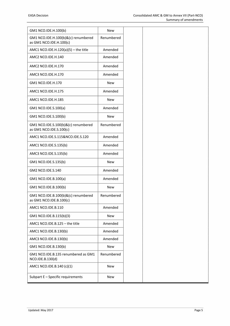
EASA Decision Consolidated AMC & GM to Annex VII (Part-NCO) Summary of amendments
Updated: May 2017 Page 5
GM1 NCO.IDE.H.100(b) New
GM1 NCO.IDE.H.100(b)&(c) renumbered as GM1 NCO.IDE.H.100(c)
Renumbered
AMC1 NCO.IDE.H.120(a)(5) – the title Amended
AMC2 NCO.IDE.H.140 Amended
AMC2 NCO.IDE.H.170 Amended
AMC3 NCO.IDE.H.170 Amended
GM1 NCO.IDE.H.170 New
AMC1 NCO.IDE.H.175 Amended
AMC1 NCO.IDE.H.185 New
GM1 NCO.IDE.S.100(a) Amended
GM1 NCO.IDE.S.100(b) New
GM1 NCO.IDE.S.100(b)&(c) renumbered as GM1 NCO.IDE.S.100(c)
Renumbered
AMC1 NCO.IDE.S.115&NCO.IDE.S.120 Amended
AMC1 NCO.IDE.S.135(b) Amended
AMC3 NCO.IDE.S.135(b) Amended
GM1 NCO.IDE.S.135(b) New
GM2 NCO.IDE.S.140 Amended
GM1 NCO.IDE.B.100(a) Amended
GM1 NCO.IDE.B.100(b) New
GM1 NCO.IDE.B.100(b)&(c) renumbered as GM1 NCO.IDE.B.100(c)
Renumbered
AMC1 NCO.IDE.B.110 Amended
GM1 NCO.IDE.B.115(b)(3) New
AMC1 NCO.IDE.B.125 – the title Amended
AMC1 NCO.IDE.B.130(b) Amended
AMC3 NCO.IDE.B.130(b) Amended
GM1 NCO.IDE.B.130(b) New
GM1 NCO.IDE.B.135 renumbered as GM1 NCO.IDE.B.130(d)
Renumbered
AMC1 NCO.IDE.B.140 (c)(1) New
Subpart E – Specific requirements New

EASA Decision Consolidated AMC & GM to Annex VII (Part-NCO) Summary of amendments
Updated: May 2017 Page 6
EASA Decision Consolidated AMC & GM to Annex VII (Part-NCO) NCO.GEN
Updated: May 2017 Page 7
SUBPART A: GENERAL REQUIREMENTS
AMC1 NCO.GEN.105 Pilot-in-command responsibilities and authority
FLIGHT PREPARATION FOR PBN OPERATIONS
(a) The pilot-in-command should ensure that RNAV 1, RNAV 2, RNP 1, RNP 2, and RNP APCH routes
or procedures to be used for the intended flight, including for any alternate aerodromes, are
selectable from the navigation database and are not prohibited by NOTAM.
(b) The pilot-in-command should take account of any NOTAMs or pilot-in-command briefing
material that could adversely affect the aircraft system operation along its flight plan including
any alternate aerodromes.
(c) When PBN relies on GNSS systems for which RAIM is required for integrity, its availability should
be verified during the preflight planning. In the event of a predicted continuous loss of fault
detection of more than five minutes, the flight planning should be revised to reflect the lack of
full PBN capability for that period.
(d) For RNP 4 operations with only GNSS sensors, a fault detection and exclusion (FDE) check should
be performed. The maximum allowable time for which FDE capability is projected to be
unavailable on any one event is 25 minutes. If predictions indicate that the maximum allowable
FDE outage will be exceeded, the operation should be rescheduled to a time when FDE is
available.
(e) For RNAV 10 operations, the pilot-in-command should take account of the RNAV 10 time limit
declared for the inertial system, if applicable, considering also the effect of weather conditions
that could affect flight duration in RNAV 10 airspace. Where an extension to the time limit is
permitted, the pilot-in-command will need to ensure that en route radio facilities are serviceable
before departure, and to apply radio updates in accordance with any AFM/POH limitation.
AMC2 NCO.GEN.105 Pilot-in-command responsibilities and authority
DATABASE SUITABILITY
(a) The pilot-in-command should check that any navigational database required for PBN operations
includes the routes and procedures required for the flight.
DATABASE CURRENCY
(b) The database validity (current AIRAC cycle) should be checked before the flight.
(c) Navigation databases should be current for the duration of the flight. If the AIRAC cycle is due
to change during flight, the pilot-in-command should follow procedures established by the pilot-
in-command to ensure the accuracy of navigation data, including the suitability of navigation
facilities used to define the routes and procedures for the flight.
(d) An expired database may only be used if the following conditions are satisfied:
(1) the pilot-in-command has confirmed that the parts of the database which are intended to
be used during the flight and any contingencies that are reasonable to expect are not
changed in the current version;
EASA Decision Consolidated AMC & GM to Annex VII (Part-NCO) NCO.GEN
Updated: May 2017 Page 8
(2) any NOTAMs associated with the navigational data are taken into account;
(3) maps and charts corresponding to those parts of the flight are current and have not been
amended since the last cycle;
(4) any MEL limitations, where available, are observed; and
(5) the database has expired by no more than 28 days.
GM1 NCO.GEN.105 Pilot-in-command responsibilities and authority
GENERAL
In accordance with 1.c. of Annex IV to Regulation (EC) No 216/20083 (essential requirements for air
operations), the pilot-in-command is responsible for the operation and safety of the aircraft and for
the safety of all passengers and cargo on board. This includes the following:
(a) the safety of all passengers and cargo on board, as soon as he/she arrives on board, until he/she
leaves the aircraft at the end of the flight; and
(b) the operation and safety of the aircraft:
(1) for aeroplanes, from the moment it is first ready to move for the purpose of flight until
the moment it comes to rest at the end of the flight and the engine(s) used as primary
propulsion unit(s) is/are shut down;
(2) for helicopters, from the moment the engine(s) are started until the helicopter comes to
rest at the end of the flight with the engine(s) shut down and the rotor blades stopped;
(3) for sailplanes, from the moment the launch procedure is started until the aircraft comes
to rest at the end of the flight; or
(4) for balloons, from the moment the inflating of the envelope is started until the envelope
is deflated.
GM1 NCO.GEN.105(a)(8) Pilot-in-command responsibilities and authority
RECORDING UTILISATION DATA
Where an aircraft conducts a series of flights of short duration — such as a helicopter doing a series of
lifts — and the aircraft is operated by the same pilot-in-command, the utilisation data for the series of
flights may be recorded in the aircraft technical log or journey log as a single entry.
AMC1 NCO.GEN.105(c) Pilot-in-command responsibilities and authority
CHECKLISTS
(a) The pilot-in-command should use the latest checklists provided by the manufacturer.
(b) If checks conducted prior to take-off are suspended at any point, the pilot-in-command should
re-start them from a safe point prior to the interruption.
3 Regulation (EC) No 216/2008 of the European Parliament and of the Council of 20 February 2008 on common rules in the field of civil
aviation and establishing a European Aviation Safety Agency, and repealing Council Directive 91/670/EEC, Regulation (EC) No 1592/2002 and Directive 2004/36/EC. OJ L 79, 19.3.2008, p. 1, as amended by Regulation (EC) No 1108/2009 of the European Parliament and of the Council of 21 October 2009, OJ L 309, 24.11.2009, p. 51.
EASA Decision Consolidated AMC & GM to Annex VII (Part-NCO) NCO.GEN
Updated: May 2017 Page 9
GM1 NCO.GEN.105(d) Pilot-in-command responsibilities and authority
REPORTING OF HAZARDOUS FLIGHT CONDITIONS
(a) These reports should include any detail which may be pertinent to the safety of other aircraft.
(b) Such reports should be made whenever any of the following conditions are encountered or
observed:
(1) severe turbulence;
(2) severe icing;
(3) severe mountain wave;
(4) thunderstorms, with or without hail, that are obscured, embedded, widespread or in
squall lines;
(5) heavy dust storm or heavy sandstorm;
(6) volcanic ash cloud; and
(7) unusual and/or increasing volcanic activity or a volcanic eruption.
(c) When other meteorological conditions not listed above, e.g. wind shear, are encountered that,
in the opinion of the pilot-in-command, may affect the safety or the efficiency of other aircraft
operations, the pilot-in-command should advise the appropriate air traffic services (ATS) unit as
soon as practicable.
AMC1 NCO.GEN.105(e) Pilot-in-command responsibilities and authority
VIOLATION REPORTING
If required by the State in which the incident occurs, the pilot-in-command should submit a report on
any such violation to the appropriate authority of such State; in that event, the pilot-in-command
should also submit a copy of it to the competent authority. Such reports should be submitted as soon
as possible and normally within 10 days.
GM1 NCO.GEN.106(b) Pilot-in-command responsibilities and authority — balloons
PROTECTIVE CLOTHING
Protective clothing includes:
(a) long sleeves and trousers preferably made out of natural fibres;
(b) stout footwear; and
(c) gloves.
GM1 NCO.GEN.115 Taxiing of aeroplanes
SAFETY-CRITICAL ACTIVITY
(a) Taxiing should be treated as a safety-critical activity due to the risks related to the movement of
the aeroplane and the potential for a catastrophic event on the ground.
(b) Taxiing is a high-workload phase of flight that requires the full attention of the pilot-in-
command.
EASA Decision Consolidated AMC & GM to Annex VII (Part-NCO) NCO.GEN
Updated: May 2017 Page 10
GM1 NCO.GEN.115(b)(4) Taxiing of aeroplanes
SKILLS AND KNOWLEDGE
The person designated by the operator to taxi an aeroplane should possess the following skills and
knowledge:
(a) positioning of the aeroplane to ensure safety when starting engine;
(b) getting ATIS reports and taxi clearance, where applicable;
(c) interpretation of airfield markings/lights/signals/indicators;
(d) interpretation of marshalling signals, where applicable;
(e) identification of suitable parking area;
(f) maintaining lookout and right-of-way rules and complying with ATC or marshalling instructions
when applicable;
(g) avoidance of adverse effect of propeller slipstream or jet wash on other aeroplanes, aerodrome
facilities and personnel;
(h) inspection of taxi path when surface conditions are obscured;
(i) communication with others when controlling an aeroplane on the ground;
(j) interpretation of operational instructions;
(k) reporting of any problem that may occur while taxiing an aeroplane; and
(l) adapting the taxi speed in accordance with prevailing aerodrome, traffic, surface and weather
conditions.
GM1 NCO.GEN.120 Rotor engagement
INTENT OF THE RULE
(a) The following two situations where it is allowed to turn the rotor under power should be
distinguished:
(1) for the purpose of flight, this is described in the implementing rule;
(2) for maintenance purposes.
(b) Rotor engagement for the purpose of flight: it should be noted that the pilot should not leave
the control when the rotors are turning. For example, the pilot is not allowed to get out of the
aircraft in order to welcome passengers and adjust their seat belts with the rotors turning.
(c) Rotor engagement for the purpose of maintenance: the implementing rule, however, should not
prevent ground runs being conducted by qualified personnel other than pilots for maintenance
purposes.
The following conditions should be applied:
(1) The operator should ensure that the qualification of personnel, other than pilots, who are
authorised to conduct maintenance runs is described in the appropriate manual.
(2) Ground runs should not include taxiing the helicopter.
(3) There should be no passengers on board.
(4) Maintenance runs should not include collective increase or auto pilot engagement (risk of
ground resonance).
EASA Decision Consolidated AMC & GM to Annex VII (Part-NCO) NCO.GEN
Updated: May 2017 Page 11
GM1 NCO.GEN.125 Portable electronic devices
DEFINITIONS
(a) Definition and categories of PEDs
PEDs are any kind of electronic device, typically but not limited to consumer electronics, brought
on board the aircraft by crew members, passengers, or as part of the cargo and that are not
included in the approved aircraft configuration. All equipment that is able to consume electrical
energy falls under this definition. The electrical energy can be provided from internal sources as
batteries (chargeable or non-rechargeable) or the devices may also be connected to specific
aircraft power sources.
PEDs include the following two categories:
(1) Non-intentional transmitters can non-intentionally radiate RF transmissions, sometimes
referred to as spurious emissions. This category includes, but is not limited to, calculators,
cameras, radio receivers, audio and video players, electronic games and toys; when these
devices are not equipped with a transmitting function.
(2) Intentional transmitters radiate RF transmissions on specific frequencies as part of their
intended function. In addition, they may radiate non-intentional transmissions like any
PED. The term ‘transmitting PED’ (T-PED) is used to identify the transmitting capability of
the PED. Intentional transmitters are transmitting devices such as RF-based remote
control equipment, which may include some toys, two-way radios (sometimes referred to
as private mobile radio), mobile phones of any type, satellite phones, computers with
mobile phone data connection, wireless local area network (WLAN) or Bluetooth
capability. After deactivation of the transmitting capability, e.g. by activating the so-called
‘flight mode’ or ‘flight safety mode’, the T-PED remains a PED having non-intentional
emissions.
(b) Definition of the switched-off status
Many PEDs are not completely disconnected from the internal power source when switched off.
The switching function may leave some remaining functionality e.g. data storage, timer, clock,
etc. These devices can be considered switched off when in the deactivated status. The same
applies for devices having no transmitting capability and are operated by coin cells without
further deactivation capability, e.g. wrist watches.
GM2 NCO.GEN.125 Portable electronic devices
GENERAL
(a) PEDs can pose a risk of interference with electronically operated aircraft systems. Those systems
could range from the electronic engine control, instruments, navigation or communication
equipment, autopilots to any other type of avionic equipment on the aircraft. The interference
can result in on-board systems malfunctioning or providing misleading information and
communication disturbance. These can also lead to an increased workload for the flight crew.
(b) Interference may be caused by transmitters being part of the PED’s functionality or by
unintentional transmissions from the PED. Due to the likely proximity of the PED to any
electronically operated aircraft system and the generally limited shielding found in small aircraft,
the risk of interference is to be considered higher than that for larger aircraft with metal
airframes.
EASA Decision Consolidated AMC & GM to Annex VII (Part-NCO) NCO.GEN
Updated: May 2017 Page 12
(c) During certification of the aircraft, when qualifying the aircraft functions consideration may only
have been made of short-term exposure to a high radiating field, with an acceptable mitigating
measure being a return to normal function after removal of the threat. This certification
assumption may not be true when operating the transmitting PED on board the aircraft.
(d) It has been found that compliance with the electromagnetic compatibility (EMC) Directive
2004/108/EC and related European standards, as indicated by the CE marking, is not sufficient
to exclude the existence of interference. A well-known interference is the demodulation of the
transmitted signal from GSM (global system for mobile communications) mobile phones leading
to audio disturbances in other systems. Similar interferences are difficult to predict during the
PED design and protecting the aircraft’s electronic systems against the full range of potential
interferences is practically impossible. Therefore, not operating PEDs on-board aircraft is the
safest option, especially as effects may not be identified immediately but under the most
inconvenient circumstances.
(e) Guidance to follow in case of fire caused by PEDs is provided by the International Civil Aviation
Organisation, ‘Emergency response guidance for aircraft incidents involving dangerous goods’,
ICAO Doc 9481-AN/928.
AMC1 NCO.GEN.130 Information on emergency and survival equipment carried
CONTENT OF INFORMATION
The information, compiled in a list, should include, as applicable:
(a) the number, colour and type of life rafts and pyrotechnics,
(b) details of emergency medical supplies and water supplies; and
(c) the type and frequencies of the emergency portable radio equipment.
AMC1 NCO.GEN.135(a)(3) Documents, manuals and information to be carried
CERTIFICATE OF AIRWORTHINESS
The certificate of airworthiness should be a normal certificate of airworthiness, a restricted certificate
of airworthiness or a permit to fly issued in accordance with the applicable airworthiness
requirements.
AMC1 NCO.GEN.135(a)(10) Documents, manuals and information to be carried
CURRENT AND SUITABLE AERONAUTICAL CHARTS
(a) The aeronautical charts carried should contain data appropriate to the applicable air traffic
regulations, rules of the air, flight altitudes, area/route and nature of the operation. Due
consideration should be given to carriage of textual and graphic representations of:
(1) aeronautical data, including, as appropriate for the nature of the operation:
(i) airspace structure;
(ii) significant points, navigation aids (navaids) and air traffic services (ATS) routes;
(iii) navigation and communication frequencies;
(iv) prohibited, restricted and danger areas; and
(v) sites of other relevant activities that may hazard the flight; and
EASA Decision Consolidated AMC & GM to Annex VII (Part-NCO) NCO.GEN
Updated: May 2017 Page 13
(2) topographical data, including terrain and obstacle data.
(b) A combination of different charts and textual data may be used to provide adequate and current
data.
(c) The aeronautical data should be appropriate for the current aeronautical information regulation
and control (AIRAC) cycle.
(d) The topographical data should be reasonably recent, having regard to the nature of the planned
operation.
GM1 NCO.GEN.135 Documents, manuals and information to be carried
GENERAL
(a) In case of loss or theft of documents specified in NCO.GEN.135, the operation may continue until
the flight reaches the base or a place where a replacement document can be provided.
(b) The documents, manuals and information may be available in a form other than on printed
paper. An electronic storage medium is acceptable if accessibility, usability and reliability can be
assured.
GM1 NCO.GEN.135(a)(1) Documents, manuals and information to be carried
AFM OR EQUIVALENT DOCUMENT
‘Aircraft flight manual (AFM), or equivalent document’ means the flight manual for the aircraft or other
documents containing information required for the operation of the aircraft within the terms of its
certificate of airworthiness.
AIRCRAFT FLIGHT MANUAL (AFM) — BALLOONS
At least the operating limitations, normal and emergency procedures should be available to the pilot
during operation by providing the specific sections of the AFM or by other means (e.g. placards, quick
reference cards) that effectively accomplish the purpose.
GM1 NCO.GEN.135(a)(8) Documents, manuals and information to be carried
JOURNEY LOG OR EQUIVALENT
’Journey log or equivalent’ means that the required information may be recorded in documentation
other than a log book, such as the operational flight plan or the aircraft technical log.
GM1 NCO.GEN.135(a)(11) Documents, manuals and information to be carried
PROCEDURES AND VISUAL SIGNALS FOR USE BY INTERCEPTING AND INTERCEPTED AIRCRAFT
The procedures and the visual signals information for use by intercepting and intercepted aircraft are
those contained in the International Civil Aviation Organisation’s (ICAO) Annex 2.
GM1 NCO.GEN.135(a)(13) Documents, manuals and information to be carried
DOCUMENTS THAT MAY BE PERTINENT TO THE FLIGHT
Any other documents that may be pertinent to the flight or required by the States concerned with the
flight may include, for example, forms to comply with reporting requirements.
EASA Decision Consolidated AMC & GM to Annex VII (Part-NCO) NCO.GEN
Updated: May 2017 Page 14
STATES CONCERNED WITH THE FLIGHT
The States concerned are those of origin, transit, overflight and destination of the flight.
AMC1 NCO.GEN.140(d) Transport of dangerous goods
DANGEROUS GOODS ACCIDENT AND INCIDENT REPORTING
(a) Any type of dangerous goods incident or accident, or the finding of:
(1) undeclared or misdeclared dangerous goods in cargo;
(2) forbidden dangerous goods in mail; or
(3) forbidden dangerous goods in passenger or crew baggage, or on the person of a passenger
or crew member
should be reported. For this purpose, the Technical Instructions consider that reporting of
undeclared and misdeclared dangerous goods found in cargo also applies to items of operators’
stores that are classified as dangerous goods.
(b) The first report should be dispatched within 72 hours of the event. It may be sent by any means,
including e-mail, telephone or fax. This report should include the details that are known at that
time, under the headings identified in 3. If necessary, a subsequent report should be made as
soon as possible giving all the details that were not known at the time the first report was sent.
If a report has been made verbally, written confirmation should be sent as soon as possible.
(c) The first and any subsequent report should be as precise as possible and contain the following
data, where relevant:
(1) date of the incident or accident or the finding of undeclared or misdeclared dangerous
goods;
(2) location and date of flight;
(3) description of the goods;
(4) proper shipping name (including the technical name, if appropriate) and United Nations
(UN)/identification (ID) number, when known;
(5) class or division and any subsidiary risk;
(6) type of packaging, and the packaging specification marking on it;
(7) quantity;
(8) name and address of the passenger, etc.;
(9) any other relevant details;
(10) suspected cause of the incident or accident;
(11) action taken;
(12) any other reporting action taken; and
(13) name, title, address and telephone number of the person making the report.
(d) Copies of relevant documents and any photographs taken should be attached to the report.
(e) A dangerous goods accident or incident may also constitute an aircraft accident, serious incident
or incident. The criteria for reporting both types of occurrence should be met.
EASA Decision Consolidated AMC & GM to Annex VII (Part-NCO) NCO.GEN
Updated: May 2017 Page 15
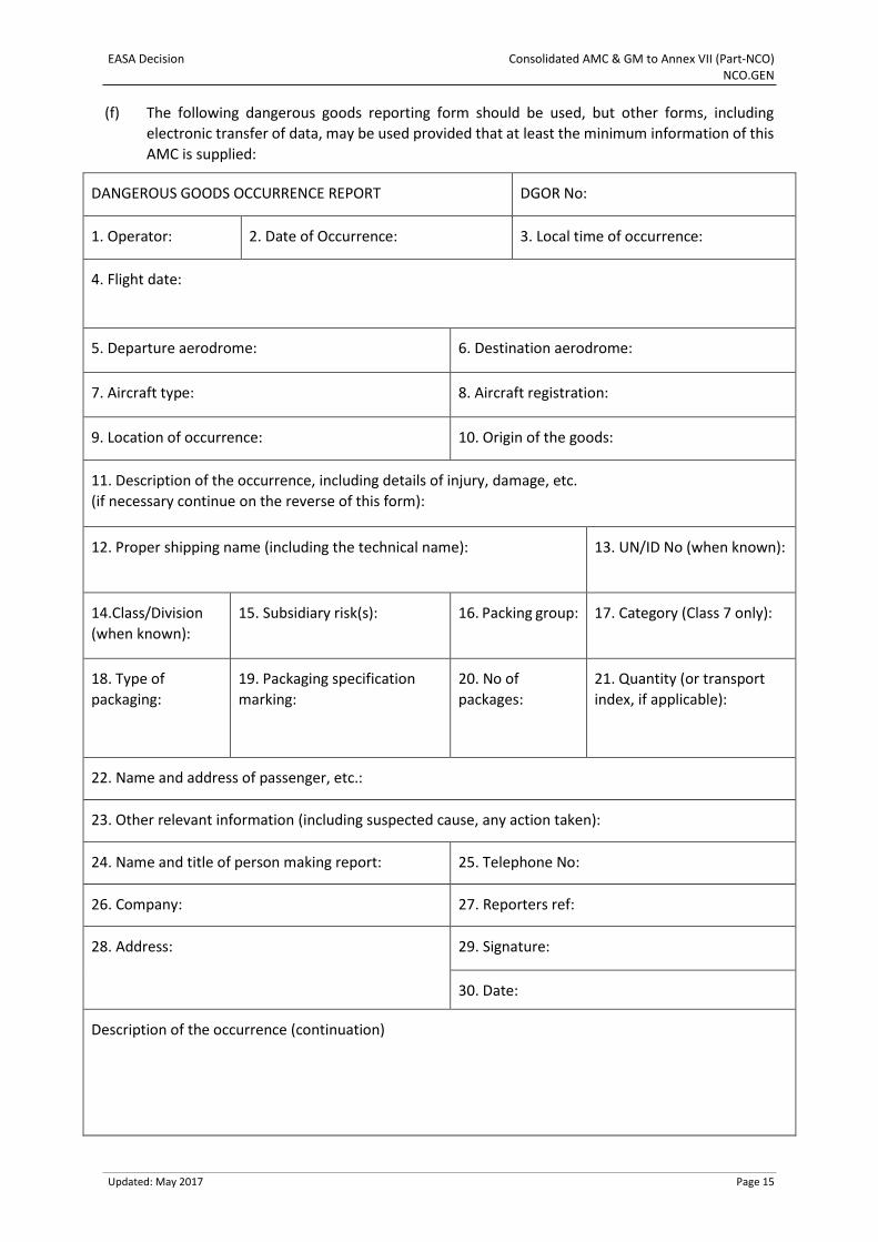
(f) The following dangerous goods reporting form should be used, but other forms, including
electronic transfer of data, may be used provided that at least the minimum information of this
AMC is supplied:
DANGEROUS GOODS OCCURRENCE REPORT DGOR No:
1. Operator: 2. Date of Occurrence: 3. Local time of occurrence:
4. Flight date:
5. Departure aerodrome: 6. Destination aerodrome:
7. Aircraft type: 8. Aircraft registration:
9. Location of occurrence: 10. Origin of the goods:
11. Description of the occurrence, including details of injury, damage, etc.
(if necessary continue on the reverse of this form):
12. Proper shipping name (including the technical name): 13. UN/ID No (when known):
14.Class/Division
(when known):
15. Subsidiary risk(s): 16. Packing group: 17. Category (Class 7 only):
18. Type of
packaging:
19. Packaging specification
marking:
20. No of
packages:
21. Quantity (or transport
index, if applicable):
22. Name and address of passenger, etc.:
23. Other relevant information (including suspected cause, any action taken):
24. Name and title of person making report: 25. Telephone No:
26. Company: 27. Reporters ref:
28. Address: 29. Signature:
30. Date:
Description of the occurrence (continuation)
EASA Decision Consolidated AMC & GM to Annex VII (Part-NCO) NCO.GEN
Updated: May 2017 Page 16
Notes for completion of the form:
1. A dangerous goods accident is as defined in Annex I. For this purpose serious injury is as defined
in Regulation (EU) No 996/2010 of the European Parliament and of the Council4.
2. The initial report should be dispatched unless exceptional circumstances prevent this. This
occurrence report form, duly completed, should be sent as soon as possible, even if all the
information is not available.
3. Copies of all relevant documents and any photographs should be attached to this report.
4. Any further information, or any information not included in the initial report, should be sent as
soon as possible to the authorities identified in NCO.GEN.140(d).
5. Providing it is safe to do so, all dangerous goods, packaging, documents, etc. relating to the
occurrence should be retained until after the initial report has been sent to the authorities
identified in NCO.GEN.140(d), and they have indicated whether or not these should continue to
be retained.
GM1 NCO.GEN.140(a) Transport of dangerous goods
GENERAL
(a) The requirement to transport dangerous goods by air in accordance with the Technical
Instructions is irrespective of whether:
(1) the flight is wholly or partly within or wholly outside the territory of a State; or
(2) an approval to carry dangerous goods in accordance with Annex V (Part-SPA), Subpart G
is held.
(b) The Technical Instructions provide that in certain circumstances dangerous goods, which are
normally forbidden on an aircraft, may be carried. These circumstances include cases of extreme
urgency or when other forms of transport are inappropriate or when full compliance with the
prescribed requirements is contrary to the public interest. In these circumstances all the States
concerned may grant exemptions from the provisions of the Technical Instructions provided that
an overall level of safety that is at least equivalent to that provided by the Technical Instructions
is achieved. Although exemptions are most likely to be granted for the carriage of dangerous
goods that are not permitted in normal circumstances, they may also be granted in other
circumstances, such as when the packaging to be used is not provided for by the appropriate
packing method or the quantity in the packaging is greater than that permitted. The Technical
Instructions also make provision for some dangerous goods to be carried when an approval has
been granted only by the State of origin and the competent authority.
(c) When an exemption is required, the States concerned are those of origin, transit, overflight and
destination of the consignment and that of the operator. For the State of overflight, if none of
the criteria for granting an exemption are relevant, an exemption may be granted based solely
on whether it is believed that an equivalent level of safety in air transport has been achieved.
(d) The Technical Instructions provide that exemptions and approvals are granted by the
‘appropriate national authority’, which is intended to be the authority responsible for the
particular aspect against which the exemption or approval is being sought. The operator should
ensure that all relevant conditions on an exemption or approval are met.
4 OJ L 295, 12.11.2010, p. 35.
EASA Decision Consolidated AMC & GM to Annex VII (Part-NCO) NCO.GEN
Updated: May 2017 Page 17
(e) The exemption or approval referred to in (b) to (d) is in addition to the approval required by
Annex V (Part-SPA), Subpart G.
AMC1 NCO.GEN.140(f) Transport of dangerous goods
GENERAL
The quantities of DG carried for operational purposes should be reasonable considering the purposes
for which they might be required before the aircraft is able to replenish its supplies, e.g. at its home
base or, in the case of a long tour, at any aerodrome along the route where the aircraft is planned to
land and where such supplies are available.
GM1 NCO.GEN.140(f) Transport of dangerous goods
GENERAL
In addition to items authorised under paragraph 1;2.2.1(a) of the Technical Instructions, the articles
and substances should be items such as, e.g. aircraft spare parts, components/substances needed for
aircraft repair, oil (for aircraft engine/gearbox), aircraft fuel, de-icing fluid, aircraft battery, and air
starter unit.
AMC1 NCO.GEN.150 Journey log
GENERAL
(a) The aircraft journey log, or equivalent, should include the following items, where applicable:
(1) aircraft nationality and registration;
(2) date;
(3) name of crew member(s);
(4) duty assignments of crew members, if applicable;
(5) place of departure;
(6) place of arrival;
(7) time of departure;
(8) time of arrival;
(9) hours of flight;
(10) nature of flight;
(11) incidents and observations (if any); and
(12) signature of the pilot-in-command.
(b) The information or parts thereof may be recorded in a form other than on printed paper.
Accessibility, usability and reliability should be assured.
EASA Decision Consolidated AMC & GM to Annex VII (Part-NCO) NCO.GEN
Updated: May 2017 Page 18
AMC1 NCO.GEN.155 Minimum equipment list
CONTENT AND APPROVAL OF THE MEL
(a) When an MEL is established, the operator should amend the MEL after any applicable change
to the MMEL within the acceptable timescales. The following are applicable changes to the
MMEL that require amendment of the MEL:
(1) a reduction of the rectification interval;
(2) change of an item, only when the change is applicable to the aircraft or type of operations
and is more restrictive;
(3) reduced timescales for the implementation of safety-related amendments may be
required by the Agency and/or the competent authority.
(b) An acceptable timescale for notifying the amended MEL to the competent authority is 90 days
from the effective date specified in the approved change to the MMEL.
(c) In addition to the list of items and related dispatch conditions, the MEL should contain:
(1) a preamble, including guidance and definitions for flight crew members and maintenance
personnel using the MEL. The MEL preamble should:
(i) reflect the content of the MMEL preamble as applicable to the MEL scope and
extent;
(ii) contain terms and definitions used in the MEL;
(iii) contain any other relevant specific information for the MEL scope and use that is
not originally provided in the MMEL;
(iv) provide guidance on how to identify the origin of a failure or malfunction to the
extent necessary for appropriate application of the MEL;
(v) provide guidance on the management of multiple unserviceabilities, based on the
guidance given in the MMEL; and
(vi) provide guidance on placarding of inoperative items to inform crew members of
equipment condition as appropriate. In particular, when such items are accessible
to the crew during flight, the control(s) and indicator(s) related to inoperative
unit(s) should be clearly placarded.
(2) the revision status of the MMEL upon which the MEL is based and the revision status of
the MEL;
(3) the scope, extent and purpose of the MEL;
(4) operational and maintenance procedures as part of the MEL or by means of reference to
another appropriate document, based on the operational and maintenance procedures
referenced in the MMEL; and
(5) the dispatch conditions associated with flights conducted in accordance with special
approvals held by the operator in accordance with Part-SPA.
(d) The operator should:
(1) establish rectification intervals for each inoperative instrument, item of equipment or
function listed in the MEL. The rectification interval in the MEL should not be less
restrictive than the corresponding rectification interval in the MMEL. The definitions and
categories of rectification intervals are provided in CS-MMEL as well as in CS-GEN-MMEL;
and
EASA Decision Consolidated AMC & GM to Annex VII (Part-NCO) NCO.GEN
Updated: May 2017 Page 19
(2) establish an effective rectification programme.
(e) The operator should establish the operational and maintenance procedures referenced in the
MEL, taking into account the operational and maintenance procedures referenced in the MMEL.
These procedures should be part of the operator’s manuals or the MEL.
(f) The operator should amend the operational and maintenance procedures referenced in the MEL
after any applicable change to the operational and maintenance procedures referenced in the
MMEL.
(g) Unless otherwise specified in the MEL, the operator should complete:
(1) the operational procedures referenced in the MEL when planning for and/or operating
with the listed item inoperative; and
(2) the maintenance procedures referenced in the MEL prior to operating with the listed item
inoperative.
AMC2 NCO.GEN.155 Minimum equipment list
FORMAT OF THE MEL
The MEL format, the presentation of MEL items and dispatch conditions should:
(a) reflect those of the MMEL;
(b) follow the ATA 100/2200 Specification numbering system for MEL items; and
(c) when different from (a) and (b), be clear and unambiguous.
AMC3 NCO.GEN.155 Minimum equipment list
EXTENT OF THE MEL
The operator should include guidance in the MEL on how to deal with any failures that occur between
the commencement of the flight and the start of the take-off. If a failure occurs between the
commencement of the flight and the start of the take-off, any decision to continue the flight should be
subject to pilot judgement and good airmanship. The pilot-in-command may refer to the MEL before
any decision to continue the flight is taken.
AMC4 NCO.GEN.155 Minimum equipment list
OPERATIONAL AND MAINTENANCE PROCEDURES
(a) The operational and maintenance procedures referenced in the MEL should be based on the
operational and maintenance procedures referenced in the MMEL. Modified procedures may,
however, be developed by the operator when they provide the same level of safety as required
by the MMEL. Modified maintenance procedures should be developed in accordance with the
applicable airworthiness requirements.
(b) Providing appropriate operational and maintenance procedures referenced in the MEL,
regardless of who developed them, is the responsibility of the operator.
(c) Any item in the MEL requiring an operational or maintenance procedure to ensure an acceptable
level of safety should be so identified in the ‘remarks’ or ‘exceptions’ column/part/section of
the MEL. This will normally be ‘(O)’ for an operational procedure, or ‘(M)’ for a maintenance
procedure. ‘(O)(M)’ means both operational and maintenance procedures are required.
EASA Decision Consolidated AMC & GM to Annex VII (Part-NCO) NCO.GEN
Updated: May 2017 Page 20
(d) The satisfactory accomplishment of all procedures, regardless of who performs them, is the
responsibility of the operator.
AMC5 NCO.GEN.155 Minimum equipment list
OPERATIONAL AND MAINTENANCE PROCEDURES — APPLICABLE CHANGES
(a) Changes to the operational and maintenance procedures referenced in the MMEL are
considered applicable and require the amendment of the maintenance and operating
procedures referenced in the MEL when:
(1) the modified procedure is applicable to the operator’s MEL; and
(2) the purpose of this change is to improve compliance with the intent of the associated
MMEL dispatch condition.
(b) An acceptable timescale for the amendments of maintenance and operating procedures, as
defined in (a), should be 90 days from the date when the amended procedures referenced in
the MMEL are made available. Reduced timescales for the implementation of safety-related
amendments may be required if the competent authority consider it necessary.
GM1 NCO.GEN.155 Minimum equipment list
GENERAL
(a) The Minimum Equipment List (MEL) is a document that lists the equipment that may be
temporarily inoperative, subject to certain conditions, at the commencement of flight. This
document is prepared by the operator for their own particular aircraft, taking account of their
aircraft configuration and all those individual variables that cannot be addressed at MMEL level,
such as operating environment, route structure, geographic location, aerodromes where spare
parts and maintenance capabilities are available, etc.
(b) The MMEL, as defined in the mandatory part of the operational suitability data established in
accordance with Regulation (EU) No 748/2012, is developed in compliance with CS-MMEL or CS-
GEN-MMEL. These Certification Specifications contain, among other, guidance intended to
standardise the level of relief granted in MMELs, in particular for items that are subject to
operational requirements. If an MMEL established as part of the operational suitability data is
not available and items subject to operational requirements are listed in the available MMEL
without specific relief or dispatch conditions but only with a reference to the operational
requirements, the operator may refer to CS-MMEL or CS-GEN-MMEL guidance material, as
applicable, to develop the relevant MEL content for such items.
GM2 NCO.GEN.155 Minimum equipment list
SCOPE OF THE MEL
(a) Examples of special approvals in accordance with Part-SPA may be:
(1) RVSM
(2) LVO
(b) When an aircraft has installed equipment which is not required for the operations conducted,
the operator may wish to delay rectification of such items for an indefinite period. Such cases
are considered to be out of the scope of the MEL, therefore modification of the aircraft is
EASA Decision Consolidated AMC & GM to Annex VII (Part-NCO) NCO.GEN
Updated: May 2017 Page 21
appropriate and deactivation, inhibition or removal of the item should be accomplished by an
appropriate approved modification procedure.
GM3 NCO.GEN.155 Minimum equipment list
PURPOSE OF THE MEL
The MEL is an alleviating document having the purpose to identify the minimum equipment and
conditions to operate safely an aircraft having inoperative equipment. Its purpose is not, however, to
encourage the operation of aircraft with inoperative equipment. It is undesirable for aircraft to be
dispatched with inoperative equipment and such operations are permitted only as a result of careful
analysis of each item to ensure that the acceptable level of safety, as intended in the applicable
airworthiness and operational requirements, is maintained. The continued operation of an aircraft in
this condition should be minimised.
GM4 NCO.GEN.155 Minimum equipment list
OPERATIONAL AND MAINTENANCE PROCEDURES
(a) Operational and maintenance procedures are an integral part of the compensating conditions
needed to maintain an acceptable level of safety, enabling the competent authority to approve
the MEL.
(b) Normally, operational procedures are accomplished by the flight crew; however, other
personnel may be qualified and authorised to perform certain functions.
(c) Normally, maintenance procedures are accomplished by the maintenance personnel; however,
other personnel may be qualified and authorised to perform certain functions in accordance
with the applicable airworthiness requirements.
(d) Operational and maintenance procedures, regardless of the document where they are
contained, should be readily available for use when needed for the application of the MEL.
(e) Unless specifically permitted by a maintenance procedure, an inoperative item may not be
removed from the aircraft.
EASA Decision Consolidated AMC & GM to Annex VII (Part-NCO) NCO.OP
Updated: May 2017 Page 22
SUBPART B: OPERATIONAL PROCEDURES
GM1 NCO.OP.100 Use of aerodromes and operating sites
BALLOONS
An adequate site is a site that the pilot-in-command considers to be satisfactory, taking account of the applicable performance requirements and site characteristics.
AMC1 NCO.OP.110 Aerodrome operating minima — aeroplanes and helicopters
TAKE-OFF OPERATIONS
(a) General:
(1) Take-off minima should be expressed as visibility (VIS) or runway visual range (RVR) limits,
taking into account all relevant factors for each aerodrome planned to be used and
aircraft characteristics. Where there is a specific need to see and avoid obstacles on
departure and/or for a forced landing, additional conditions, e.g. ceiling, it should be
specified.
(2) When the reported meteorological visibility is below that required for take-off and RVR is
not reported, a take-off should only be commenced if the pilot-in-command can
determine that the visibility along the take-off runway/area is equal to or better than the
required minimum.
(3) When no reported meteorological visibility or RVR is available, a take-off should only be
commenced if the pilot-in-command can determine that the RVR/VIS along the take-off
runway/area is equal to or better than the required minimum.
(b) Visual reference:
(1) The take-off minima should be selected to ensure sufficient guidance to control the
aircraft in the event of both a rejected take-off in adverse circumstances and a continued
take-off after failure of the critical engine.
(2) For night operations, ground lights should be available to illuminate the runway/final
approach and take-off area (FATO) and any obstacles.
AMC2 NCO.OP.110 Aerodrome operating minima — aeroplanes and helicopters
VISUAL APPROACH
For a visual approach operation, the RVR should not be less than 800 m.
AMC3 NCO.OP.110 Aerodrome operating minima — aeroplanes and helicopters
EFFECT ON LANDING MINIMA OF TEMPORARILY FAILED OR DOWNGRADED GROUND EQUIPMENT
(a) Non-precision approaches requiring a final approach fix (FAF) and/or missed approach point
(MAPt) should not be conducted where a method of identifying the appropriate fix is not
available.
EASA Decision Consolidated AMC & GM to Annex VII (Part-NCO) NCO.OP
Updated: May 2017 Page 23
(b) A minimum RVR of 750 m should be used for CAT I approaches in the absence of centreline lines
and/or touchdown zone lights.
(c) Where approach lighting is partly unavailable, minima should take account of the serviceable
length of approach lighting.
GM1 NCO.OP.110 Aerodrome operating minima — aeroplanes and helicopters
COMMERCIALLY AVAILABLE INFORMATION
An acceptable method of selecting aerodrome operating minima is through the use of commercially
available information.
GM2 NCO.OP.110 Aerodrome operating minima — aeroplanes and helicopters
VERTICAL PATH CONTROL
Due consideration should be given to the selection of an appropriate technique for vertical path
control on non-precision approaches (NPAs). Where appropriate instrumentation and/or facilities are
available, a continuous descent final approach technique (CDFA) usually offers increased safety and a
lower workload compared to a step-down approach.
GM3 NCO.OP.110 Aerodrome operating minima — aeroplanes and helicopters
CRITERIA FOR ESTABLISHING RVR/CMV
(a) In order to qualify for the lowest allowable values of RVR/CMV specified in Table 3.A, the
instrument approach should meet at least the following facility requirements and associated
conditions:
(1) Instrument approaches with designated vertical profile up to and including 4.5° for
Category A and B aeroplanes, or 3.77° for Category C and D aeroplanes, where the
facilities are:
(i) instrument landing system (ILS)/microwave landing system (MLS)/GBAS landing
system (GLS)/precision approach radar (PAR); or
(ii) approach procedure with vertical guidance (APV); and
where the final approach track is offset by not more than 15° for Category A and B
aeroplanes or by not more than 5° for Category C and D aeroplanes.
(2) Instrument approach operations flown using the CDFA technique with a nominal vertical
profile, up to and including 4.5° for Category A and B aeroplanes, or 3.77° for Category C
and D aeroplanes, where the facilities are non-directional beacon (NDB), NDB/distance
measuring equipment (DME), VHF omnidirectional radio range (VOR), VOR/DME, localiser
(LOC), LOC/DME, VHF direction finder (VDF), surveillance radar approach (SRA) or global
navigation satellite system (GNSS)/lateral navigation (LNAV), with a final approach
segment of at least 3 NM, which also fulfil the following criteria:
(i) the final approach track is offset by not more than 15° for Category A and B
aeroplanes or by not more than 5° for Category C and D aeroplanes;
(ii) the final approach fix (FAF) or another appropriate fix where descent is initiated is
available, or distance to threshold (THR) is available by flight management system
(FMS)/area navigation (NDB/DME) or DME; and
EASA Decision Consolidated AMC & GM to Annex VII (Part-NCO) NCO.OP
Updated: May 2017 Page 24
(iii) the missed approach point (MAPt) is determined by timing, the distance from FAF
to THR is ≤ 8 NM.
(3) Instrument approaches where the facilities are NDB, NDB/DME, VOR, VOR/DME, LOC,
LOC/DME, VDF, SRA or GNSS/LNAV, not fulfilling the criteria in (a)(2), or with an minimum
descent height (MDH) ≥ 1 200 ft.
(b) The missed approach operation, after an approach operation has been flown using the CDFA
technique, should be executed when reaching the decision height/altitude (DH/A) or the MAPt,
whichever occurs first. The lateral part of the missed approach procedure should be flown via
the MAPt unless otherwise stated on the approach chart.
GM4 NCO.OP.110 Aerodrome operating minima — aeroplanes and helicopters
DETERMINATION OF RVR/CMV/VIS MINIMA FOR NPA, APV, CAT I — AEROPLANES
(a) The minimum RVR/CMV/VIS should be the highest of the values specified in Table 2 and
Table 3.A but not greater than the maximum values specified in Table 3.A, where applicable.
(b) The values in Table 2 should be derived from the formula below:
required RVR/VIS (m) = [(DH/MDH (ft) x 0.3048) / tanα] – length of approach lights (m);
where α is the calculation angle, being a default value of 3.00° increasing in steps of 0.10°
for each line in Table 2 up to 3.77° and then remaining constant.
(c) If the approach is flown with a level flight segment at or above MDA/H, 200 m should be added
for Category A and B aeroplanes and 400 m for Category C and D aeroplanes to the minimum
RVR/CMV/VIS value resulting from the application of Table 2 and Table 3.A.
(d) An RVR of less than 750 m, as indicated in Table 2, may be used:
(1) for CAT I operations to runways with full approach lighting system (FALS), runway
touchdown zone lights (RTZL) and runway centreline lights (RCLL);
(2) for CAT I operations to runways without RTZL and RCLL when using an approved head-up
guidance landing system (HUDLS), or equivalent approved system, or when conducting a
coupled approach or flight-director-flown approach to a DH. The instrument landing
system (ILS) should not be published as a restricted facility; and
(3) for approach procedure with vertical guidance (APV) operations to runways with FALS,
RTZL and RCLL when using an approved head-up display (HUD).
(e) Lower values than those specified in Table 2 may be used for HUDLS and auto-land operations
if approved in accordance with SPA.LVO.
(f) The visual aids should comprise standard runway day markings and approach and runway lights
as specified in Table 1. The competent authority may approve that RVR values relevant to a basic
approach lighting system (BALS) are used on runways where the approach lights are restricted
in length below 210 m due to terrain or water, but where at least one cross-bar is available.
(g) For night operations or for any operation where credit for runway and approach lights is
required, the lights should be on and serviceable, except as provided for in Table 1.
(h) For single-pilot operations, the minimum RVR/VIS should be calculated in accordance with the
following additional criteria:
(1) an RVR of less than 800 m, as indicated in Table 2, may be used for CAT I approaches
provided any of the following is used at least down to the applicable DH:
EASA Decision Consolidated AMC & GM to Annex VII (Part-NCO) NCO.OP
Updated: May 2017 Page 25
(i) a suitable autopilot, coupled to an ILS, microwave landing system (MLS) or GBAS
landing system (GLS) that is not published as restricted; or
(ii) an approved HUDLS, including, where appropriate, enhanced vision system (EVS),
or equivalent approved system;
(2) where RTZL and/or RCLL are not available, the minimum RVR/CMV should not be less than
600 m; and
(3) an RVR of less than 800 m, as indicated in Table 2, may be used for APV operations to
runways with FALS, RTZL and RCLL when using an approved HUDLS, or equivalent
approved system, or when conducting a coupled approach to a DH equal to or greater
than 250 ft.
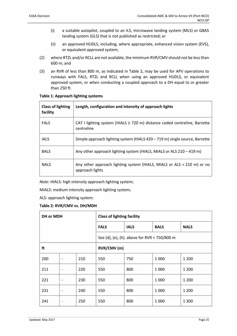
Table 1: Approach lighting systems
Class of lighting
facility
Length, configuration and intensity of approach lights
FALS CAT I lighting system (HIALS ≥ 720 m) distance coded centreline, Barrette
centreline
IALS Simple approach lighting system (HIALS 420 – 719 m) single source, Barrette
BALS Any other approach lighting system (HIALS, MIALS or ALS 210 – 419 m)
NALS Any other approach lighting system (HIALS, MIALS or ALS < 210 m) or no
approach lights
Note: HIALS: high intensity approach lighting system;
MIALS: medium intensity approach lighting system;
ALS: approach lighting system.
Table 2: RVR/CMV vs. DH/MDH
DH or MDH Class of lighting facility
FALS IALS BALS NALS
See (d), (e), (h). above for RVR < 750/800 m
ft RVR/CMV (m)
200 - 210 550 750 1 000 1 200
211 - 220 550 800 1 000 1 200
221 - 230 550 800 1 000 1 200
231 - 240 550 800 1 000 1 200
241 - 250 550 800 1 000 1 300
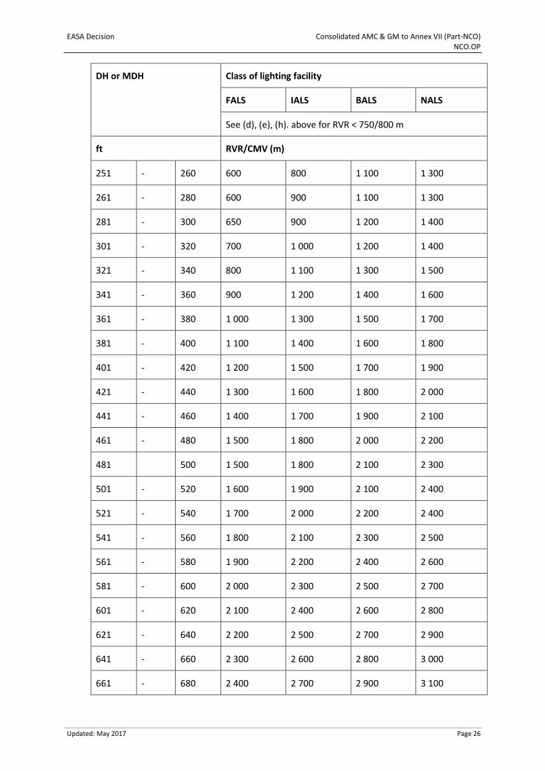
EASA Decision Consolidated AMC & GM to Annex VII (Part-NCO) NCO.OP
Updated: May 2017 Page 26
DH or MDH Class of lighting facility
FALS IALS BALS NALS
See (d), (e), (h). above for RVR < 750/800 m
ft RVR/CMV (m)
251 - 260 600 800 1 100 1 300
261 - 280 600 900 1 100 1 300
281 - 300 650 900 1 200 1 400
301 - 320 700 1 000 1 200 1 400
321 - 340 800 1 100 1 300 1 500
341 - 360 900 1 200 1 400 1 600
361 - 380 1 000 1 300 1 500 1 700
381 - 400 1 100 1 400 1 600 1 800
401 - 420 1 200 1 500 1 700 1 900
421 - 440 1 300 1 600 1 800 2 000
441 - 460 1 400 1 700 1 900 2 100
461 - 480 1 500 1 800 2 000 2 200
481 500 1 500 1 800 2 100 2 300
501 - 520 1 600 1 900 2 100 2 400
521 - 540 1 700 2 000 2 200 2 400
541 - 560 1 800 2 100 2 300 2 500
561 - 580 1 900 2 200 2 400 2 600
581 - 600 2 000 2 300 2 500 2 700
601 - 620 2 100 2 400 2 600 2 800
621 - 640 2 200 2 500 2 700 2 900
641 - 660 2 300 2 600 2 800 3 000
661 - 680 2 400 2 700 2 900 3 100
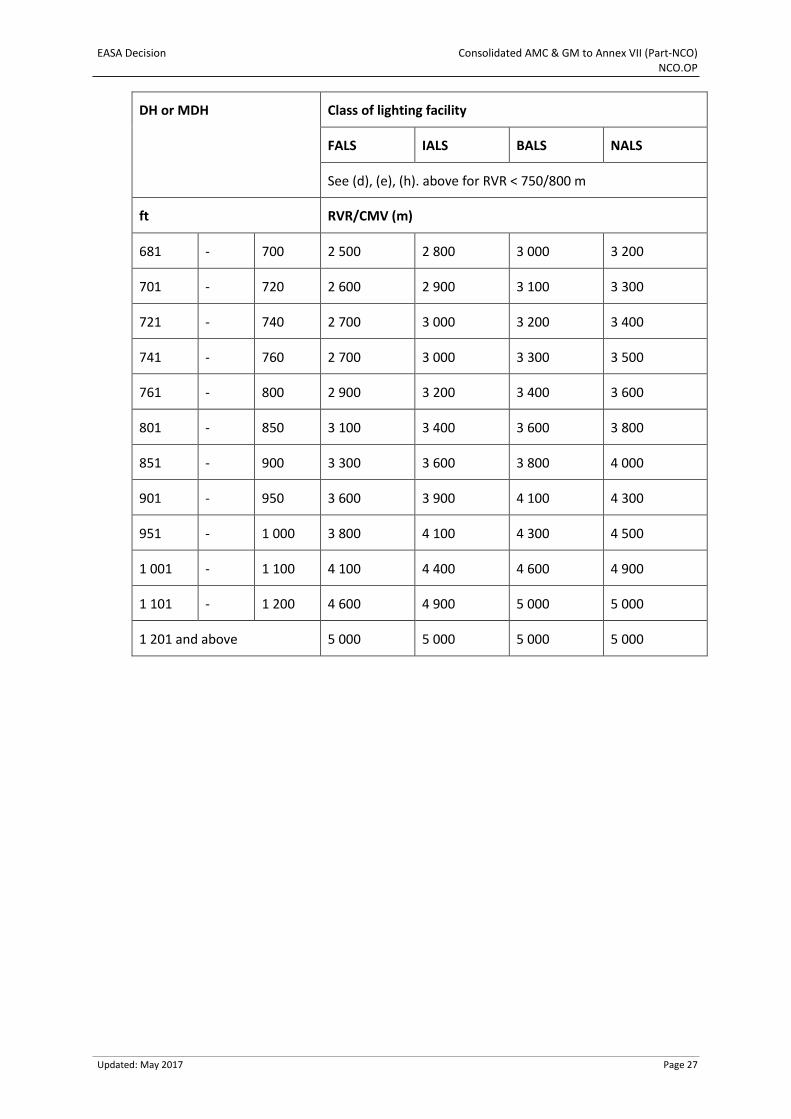
EASA Decision Consolidated AMC & GM to Annex VII (Part-NCO) NCO.OP
Updated: May 2017 Page 27
DH or MDH Class of lighting facility
FALS IALS BALS NALS
See (d), (e), (h). above for RVR < 750/800 m
ft RVR/CMV (m)
681 - 700 2 500 2 800 3 000 3 200
701 - 720 2 600 2 900 3 100 3 300
721 - 740 2 700 3 000 3 200 3 400
741 - 760 2 700 3 000 3 300 3 500
761 - 800 2 900 3 200 3 400 3 600
801 - 850 3 100 3 400 3 600 3 800
851 - 900 3 300 3 600 3 800 4 000
901 - 950 3 600 3 900 4 100 4 300
951 - 1 000 3 800 4 100 4 300 4 500
1 001 - 1 100 4 100 4 400 4 600 4 900
1 101 - 1 200 4 600 4 900 5 000 5 000
1 201 and above 5 000 5 000 5 000 5 000
EASA Decision Consolidated AMC & GM to Annex VII (Part-NCO) NCO.OP
Updated: May 2017 Page 28
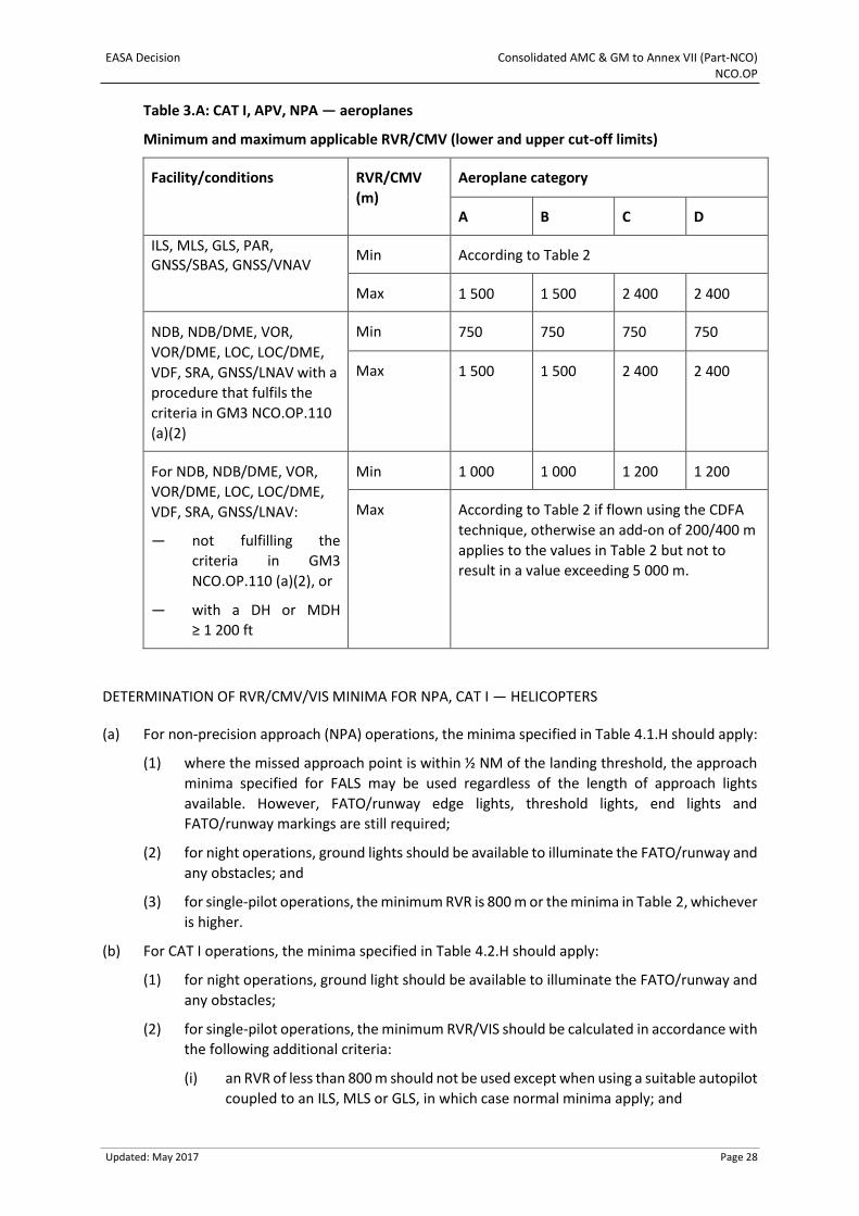
Table 3.A: CAT I, APV, NPA — aeroplanes
Minimum and maximum applicable RVR/CMV (lower and upper cut-off limits)
Facility/conditions RVR/CMV
(m)
Aeroplane category
A B C D
ILS, MLS, GLS, PAR, GNSS/SBAS, GNSS/VNAV
Min According to Table 2
Max 1 500 1 500 2 400 2 400
NDB, NDB/DME, VOR,
VOR/DME, LOC, LOC/DME,
VDF, SRA, GNSS/LNAV with a
procedure that fulfils the
criteria in GM3 NCO.OP.110
(a)(2)
Min 750 750 750 750
Max 1 500 1 500 2 400 2 400
For NDB, NDB/DME, VOR,
VOR/DME, LOC, LOC/DME,
VDF, SRA, GNSS/LNAV:
— not fulfilling the
criteria in GM3
NCO.OP.110 (a)(2), or
— with a DH or MDH
≥ 1 200 ft
Min 1 000 1 000 1 200 1 200
Max According to Table 2 if flown using the CDFA
technique, otherwise an add-on of 200/400 m
applies to the values in Table 2 but not to
result in a value exceeding 5 000 m.
DETERMINATION OF RVR/CMV/VIS MINIMA FOR NPA, CAT I — HELICOPTERS
(a) For non-precision approach (NPA) operations, the minima specified in Table 4.1.H should apply:
(1) where the missed approach point is within ½ NM of the landing threshold, the approach
minima specified for FALS may be used regardless of the length of approach lights
available. However, FATO/runway edge lights, threshold lights, end lights and
FATO/runway markings are still required;
(2) for night operations, ground lights should be available to illuminate the FATO/runway and
any obstacles; and
(3) for single-pilot operations, the minimum RVR is 800 m or the minima in Table 2, whichever
is higher.
(b) For CAT I operations, the minima specified in Table 4.2.H should apply:
(1) for night operations, ground light should be available to illuminate the FATO/runway and
any obstacles;
(2) for single-pilot operations, the minimum RVR/VIS should be calculated in accordance with
the following additional criteria:
(i) an RVR of less than 800 m should not be used except when using a suitable autopilot
coupled to an ILS, MLS or GLS, in which case normal minima apply; and
EASA Decision Consolidated AMC & GM to Annex VII (Part-NCO) NCO.OP
Updated: May 2017 Page 29
(ii) the DH applied should not be less than 1.25 times the minimum use height for the
autopilot.
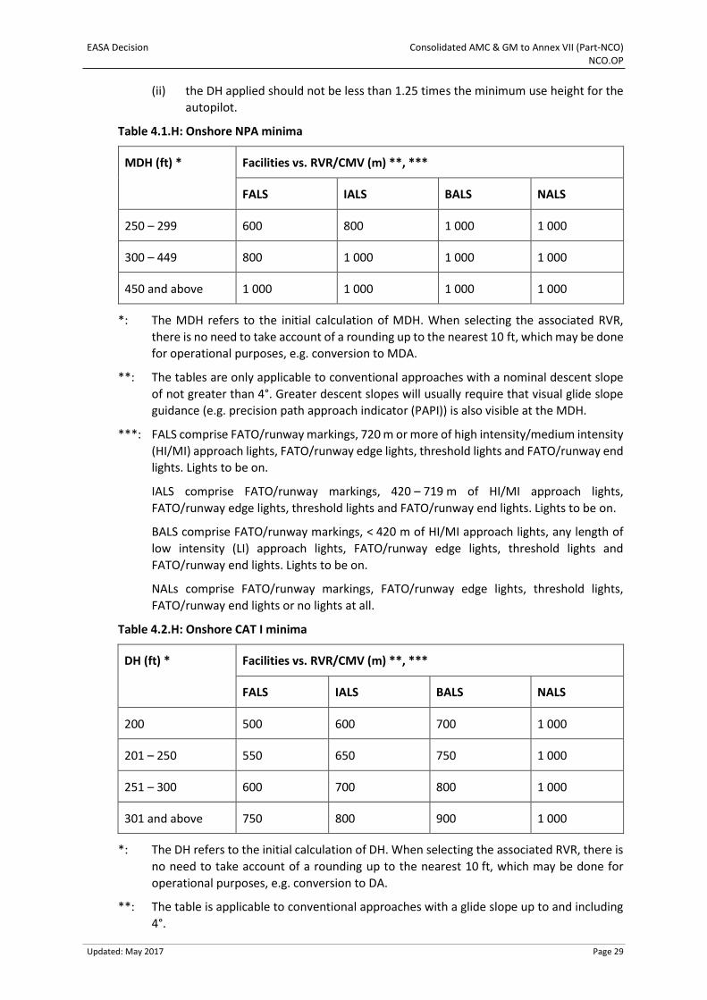
Table 4.1.H: Onshore NPA minima
MDH (ft) *
Facilities vs. RVR/CMV (m) **, ***
FALS IALS BALS NALS
250 – 299 600 800 1 000 1 000
300 – 449 800 1 000 1 000 1 000
450 and above 1 000 1 000 1 000 1 000
*: The MDH refers to the initial calculation of MDH. When selecting the associated RVR,
there is no need to take account of a rounding up to the nearest 10 ft, which may be done
for operational purposes, e.g. conversion to MDA.
**: The tables are only applicable to conventional approaches with a nominal descent slope
of not greater than 4°. Greater descent slopes will usually require that visual glide slope
guidance (e.g. precision path approach indicator (PAPI)) is also visible at the MDH.
***: FALS comprise FATO/runway markings, 720 m or more of high intensity/medium intensity
(HI/MI) approach lights, FATO/runway edge lights, threshold lights and FATO/runway end
lights. Lights to be on.
IALS comprise FATO/runway markings, 420 – 719 m of HI/MI approach lights,
FATO/runway edge lights, threshold lights and FATO/runway end lights. Lights to be on.
BALS comprise FATO/runway markings, < 420 m of HI/MI approach lights, any length of
low intensity (LI) approach lights, FATO/runway edge lights, threshold lights and
FATO/runway end lights. Lights to be on.
NALs comprise FATO/runway markings, FATO/runway edge lights, threshold lights,
FATO/runway end lights or no lights at all.
Table 4.2.H: Onshore CAT I minima
DH (ft) * Facilities vs. RVR/CMV (m) **, ***
FALS IALS BALS NALS
200 500 600 700 1 000
201 – 250 550 650 750 1 000
251 – 300 600 700 800 1 000
301 and above 750 800 900 1 000
*: The DH refers to the initial calculation of DH. When selecting the associated RVR, there is
no need to take account of a rounding up to the nearest 10 ft, which may be done for
operational purposes, e.g. conversion to DA.
**: The table is applicable to conventional approaches with a glide slope up to and including
4°.
EASA Decision Consolidated AMC & GM to Annex VII (Part-NCO) NCO.OP
Updated: May 2017 Page 30
***: FALS comprise FATO/runway markings, 720 m or more of HI/MI approach lights,
FATO/runway edge lights, threshold lights and FATO/runway end lights. Lights to be on.
IALS comprise FATO/runway markings, 420 – 719 m of HI/MI approach lights,
FATO/runway edge lights, threshold lights and FATO/runway end lights. Lights to be on.
BALS comprise FATO/runway markings, < 420 m of HI/MI approach lights, any length of LI
approach lights, FATO/runway edge lights, threshold lights and FATO/runway end lights.
Lights to be on.
NALS comprise FATO/runway markings, FATO/runway edge lights, threshold lights,
FATO/runway end lights or no lights at all.
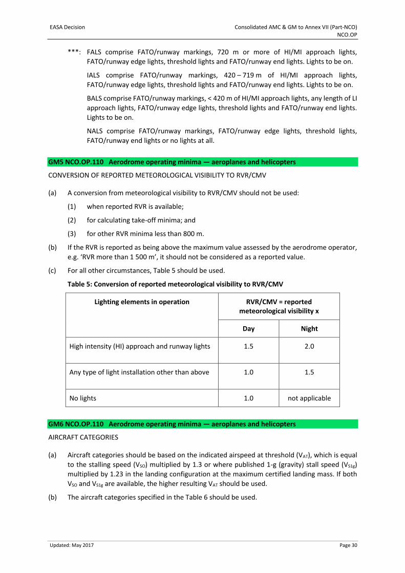
GM5 NCO.OP.110 Aerodrome operating minima — aeroplanes and helicopters
CONVERSION OF REPORTED METEOROLOGICAL VISIBILITY TO RVR/CMV
(a) A conversion from meteorological visibility to RVR/CMV should not be used:
(1) when reported RVR is available;
(2) for calculating take-off minima; and
(3) for other RVR minima less than 800 m.
(b) If the RVR is reported as being above the maximum value assessed by the aerodrome operator,
e.g. ‘RVR more than 1 500 m’, it should not be considered as a reported value.
(c) For all other circumstances, Table 5 should be used.
Table 5: Conversion of reported meteorological visibility to RVR/CMV
Lighting elements in operation RVR/CMV = reported meteorological visibility x
Day Night
High intensity (HI) approach and runway lights 1.5 2.0
Any type of light installation other than above 1.0 1.5
No lights 1.0 not applicable
GM6 NCO.OP.110 Aerodrome operating minima — aeroplanes and helicopters
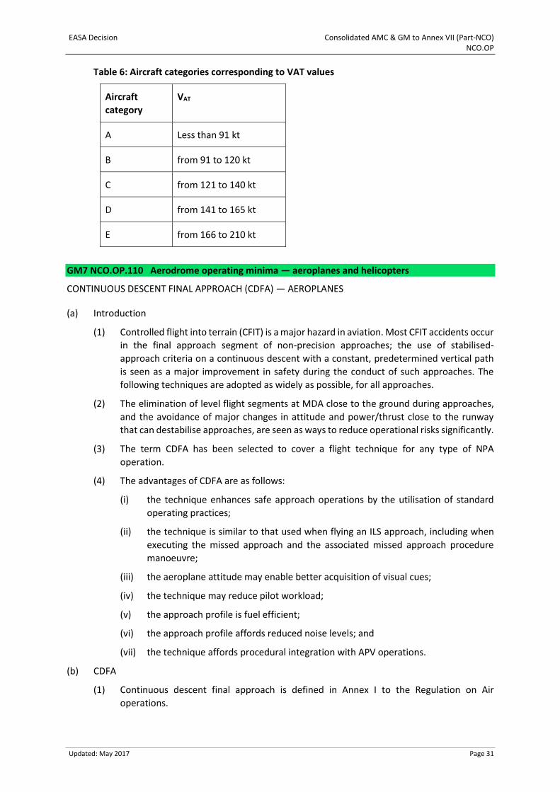
AIRCRAFT CATEGORIES
(a) Aircraft categories should be based on the indicated airspeed at threshold (VAT), which is equal
to the stalling speed (VSO) multiplied by 1.3 or where published 1-g (gravity) stall speed (VS1g)
multiplied by 1.23 in the landing configuration at the maximum certified landing mass. If both
VSO and VS1g are available, the higher resulting VAT should be used.
(b) The aircraft categories specified in the Table 6 should be used.
EASA Decision Consolidated AMC & GM to Annex VII (Part-NCO) NCO.OP
Updated: May 2017 Page 31
Table 6: Aircraft categories corresponding to VAT values
Aircraft
category
VAT
A Less than 91 kt
B from 91 to 120 kt
C from 121 to 140 kt
D from 141 to 165 kt
E from 166 to 210 kt
GM7 NCO.OP.110 Aerodrome operating minima — aeroplanes and helicopters
CONTINUOUS DESCENT FINAL APPROACH (CDFA) — AEROPLANES
(a) Introduction
(1) Controlled flight into terrain (CFIT) is a major hazard in aviation. Most CFIT accidents occur
in the final approach segment of non-precision approaches; the use of stabilised-
approach criteria on a continuous descent with a constant, predetermined vertical path
is seen as a major improvement in safety during the conduct of such approaches. The
following techniques are adopted as widely as possible, for all approaches.
(2) The elimination of level flight segments at MDA close to the ground during approaches,
and the avoidance of major changes in attitude and power/thrust close to the runway
that can destabilise approaches, are seen as ways to reduce operational risks significantly.
(3) The term CDFA has been selected to cover a flight technique for any type of NPA
operation.
(4) The advantages of CDFA are as follows:
(i) the technique enhances safe approach operations by the utilisation of standard
operating practices;
(ii) the technique is similar to that used when flying an ILS approach, including when
executing the missed approach and the associated missed approach procedure
manoeuvre;
(iii) the aeroplane attitude may enable better acquisition of visual cues;
(iv) the technique may reduce pilot workload;
(v) the approach profile is fuel efficient;
(vi) the approach profile affords reduced noise levels; and
(vii) the technique affords procedural integration with APV operations.
(b) CDFA
(1) Continuous descent final approach is defined in Annex I to the Regulation on Air
operations.
EASA Decision Consolidated AMC & GM to Annex VII (Part-NCO) NCO.OP
Updated: May 2017 Page 32
(2) An approach is only suitable for application of a CDFA technique when it is flown along a
nominal vertical profile; a nominal vertical profile is not forming part of the approach
procedure design, but can be flown as a continuous descent. The nominal vertical profile
information may be published or displayed on the approach chart to the pilot by depicting
the nominal slope or range/distance vs. height. Approaches with a nominal vertical profile
are considered to be:
(i) NDB, NDB/DME (non-directional beacon/distance measuring equipment);
(ii) VOR (VHF omnidirectional radio range), VOR/DME;
(iii) LOC (localiser), LOC/DME;
(iv) VDF (VHF direction finder), SRA (surveillance radar approach); and
(v) GNSS/LNAV (global navigation satellite system/lateral navigation).
(3) Stabilised approach (SAp) is defined in Annex I to the Regulation on Air operations.
(i) The control of the descent path is not the only consideration when using the CDFA
technique. Control of the aeroplane’s configuration and energy is also vital to the
safe conduct of an approach.
(ii) The control of the flight path, described above as one of the requirements for
conducting an SAp, should not be confused with the path requirements for using
the CDFA technique.
(iii) The predetermined approach slope requirements for applying the CDFA technique
are established by the following:
(A) the published ‘nominal’ slope information when the approach has a nominal
vertical profile; and
(B) the designated final-approach segment minimum of 3 NM, and maximum,
when using timing techniques, of 8 NM.
(iv) An SAp will never have any level segment of flight at DA/H or MDA/H, as applicable.
This enhances safety by mandating a prompt missed approach procedure
manoeuvre at DA/H or MDA/H.
(v) An approach using the CDFA technique will always be flown as an SAp, since this is
a requirement for applying CDFA. However, an SAp does not have to be flown using
the CDFA technique, for example a visual approach.
GM8 NCO.OP.110 Aerodrome operating minima — aeroplanes and helicopters
ONSHORE AERODROME DEPARTURE PROCEDURES — HELICOPTERS
The cloud base and visibility should be such as to allow the helicopter to be clear of cloud at the take-
off decision point (TDP), and for the pilot flying to remain in sight of the surface until reaching the
minimum speed for flight in instrument meteorological conditions, as given in the AFM.
AMC1 NCO.OP.111 Aerodrome operating minima — NPA, APV, CAT I operations
NPA FLOWN WITH THE CDFA TECHNIQUE
When flying a non-precision approach operation using the CDFA technique, the pilot-in-command
should ensure that when executing a missed approach, the initiation of the go-around is done at or
above the DA/H to avoid flying below the MDA/H.
EASA Decision Consolidated AMC & GM to Annex VII (Part-NCO) NCO.OP
Updated: May 2017 Page 33
GM1 NCO.OP.112 Aerodrome operating minima — circling operations with aeroplanes
SUPPLEMENTAL INFORMATION
(a) The purpose of this Guidance Material is to provide pilots with supplemental information
regarding the application of aerodrome operating minima in relation to circling approaches.
(b) Conduct of flight — general:
(1) the MDH and obstacle clearance height (OCH) included in the procedure are referenced
to aerodrome elevation;
(2) the MDA is referenced to mean sea level; and
(3) for these procedures, the applicable visibility is the meteorological visibility.
(c) Instrument approach followed by visual manoeuvring (circling) without prescribed tracks:
(1) When the aeroplane is on the initial instrument approach, before visual reference is
stabilised, but not below MDA/H — the aeroplane should follow the corresponding
instrument approach procedure until the appropriate instrument MAPt is reached.
(2) At the beginning of the level flight phase at or above the MDA/H, the instrument approach
track determined by radio navigation aids, RNAV, RNP or ILS, microwave landing system
(MLS) or GBAS landing system (GLS) should be maintained until the pilot:
(i) estimates that, in all probability, visual contact with the runway of intended landing
or the runway environment will be maintained during the entire circling procedure;
(ii) estimates that the aeroplane is within the circling area before commencing circling;
and
(iii) is able to determine the aeroplane’s position in relation to the runway of intended
landing with the aid of the appropriate external references.
(3) When reaching the published instrument MAPt and the conditions stipulated in (c)(2) are
unable to be established by the pilot, a missed approach should be carried out in
accordance with that instrument approach procedure.
(4) After the aeroplane has left the track of the initial instrument approach, the flight phase
outbound from the runway should be limited to an appropriate distance, which is
required to align the aeroplane onto the final approach. Such manoeuvres should be
conducted to enable the aeroplane:
(i) to attain a controlled and stable descent path to the intended landing runway; and
(ii) to remain within the circling area and in such a way that visual contact with the
runway of intended landing or runway environment is maintained at all times.
(5) Flight manoeuvres should be carried out at an altitude/height that is not less than the
circling MDA/H.
(6) Descent below MDA/H should not be initiated until the threshold of the runway to be
used has been appropriately identified. The aeroplane should be in a position to continue
with a normal rate of descent and land within the touchdown zone.
(d) Instrument approach followed by a visual manoeuvring (circling) with prescribed track:
(1) The aeroplane should remain on the initial instrument approach procedure until one of
the following is reached:
(i) the prescribed divergence point to commence circling on the prescribed track; or
EASA Decision Consolidated AMC & GM to Annex VII (Part-NCO) NCO.OP
Updated: May 2017 Page 34
(ii) the MAPt.
(2) The aeroplane should be established on the instrument approach track determined by the
radio navigation aids, RNAV, RNP, or ILS, MLS or GLS in level flight at or above the MDA/H
at or by the circling manoeuvre divergence point.
(3) If the divergence point is reached before the required visual reference is acquired, a
missed approach should be initiated not later than the MAPt and completed in
accordance with the initial instrument approach procedure.
(4) When commencing the prescribed circling manoeuvre at the published divergence point,
the subsequent manoeuvres should be conducted to comply with the published routing
and published heights/altitudes.
(5) Unless otherwise specified, once the aeroplane is established on the prescribed track(s),
the published visual reference does not need to be maintained unless:
(i) required by the State of the aerodrome; or
(ii) the circling MAPt (if published) is reached.
(6) If the prescribed circling manoeuvre has a published MAPt and the required visual
reference has not been obtained by that point, a missed approach should be executed in
accordance with (e)(2) and (e)(3).
(7) Subsequent further descent below MDA/H should only commence when the required
visual reference has been obtained.
(8) Unless otherwise specified in the procedure, final descent should not be commenced
from MDA/H until the threshold of the intended landing runway has been identified and
the aeroplane is in a position to continue with a normal rate of descent to land within the
touchdown zone.
(e) Missed approach:
(1) Missed approach during the instrument procedure prior to circling:
(i) if the missed approach is required to be flown when the aeroplane is positioned on
the instrument approach track defined by radio navigation aids, RNAV, RNP or ILS,
MLS or GLS and before commencing the circling manoeuvre, the published missed
approach for the instrument approach should be followed; or
(ii) if the instrument approach procedure is carried out with the aid of an ILS, MLS or a
stabilised approach (SAp), the MAPt associated with an ILS or MLS procedure
without glide path (GP-out procedure) or the SAp, where applicable, should be
used.
(2) If a prescribed missed approach is published for the circling manoeuvre, this overrides the
manoeuvres prescribed below.
(3) If visual reference is lost while circling to land after the aeroplane has departed from the
initial instrument approach track, the missed approach specified for that particular
instrument approach should be followed. It is expected that the pilot will make an initial
climbing turn toward the intended landing runway to a position overhead of the
aerodrome where the pilot will establish the aeroplane in a climb on the instrument
missed approach segment.
(4) The aeroplane should not leave the visual manoeuvring (circling) area, which is obstacle
protected, unless:
EASA Decision Consolidated AMC & GM to Annex VII (Part-NCO) NCO.OP
Updated: May 2017 Page 35
(i) established on the appropriate missed approach procedure; or
(ii) at minimum sector altitude (MSA).
(5) All turns should be made in the same direction and the aeroplane should remain within
the circling protected area while climbing either:
(i) to the altitude assigned to any published circling missed approach manoeuvre if
applicable;
(ii) to the altitude assigned to the missed approach of the initial instrument approach;
(iii) to the MSA;
(iv) to the minimum holding altitude (MHA) applicable for transition to a holding facility
or fix, or continue to climb to an MSA; or
(v) as directed by ATS.
When the missed approach procedure is commenced on the ‘downwind’ leg of the circling
manoeuvre, an ‘S’ turn may be undertaken to align the aeroplane on the initial instrument
approach missed approach path, provided the aeroplane remains within the protected
circling area.
The pilot-in-command should be responsible for ensuring adequate terrain clearance
during the above-stipulated manoeuvres, particularly during the execution of a missed
approach initiated by ATS.
(6) Because the circling manoeuvre may be accomplished in more than one direction,
different patterns will be required to establish the aeroplane on the prescribed missed
approach course, depending on its position at the time visual reference is lost. In
particular, all turns are to be in the prescribed direction if this is restricted, e.g. to the
west/east (left or right hand) to remain within the protected circling area.
(7) If a missed approach procedure is published for a particular runway onto which the
aeroplane is conducting a circling approach and the aeroplane has commenced a
manoeuvre to align with the runway, the missed approach for this direction may be
accomplished. The ATS unit should be informed of the intention to fly the published
missed approach procedure for that particular runway.
(8) The pilot-in-command should advise ATS when any missed approach procedure has been
commenced, the height/altitude the aeroplane is climbing to and the position the
aeroplane is proceeding towards and/or heading the aeroplane is established on.
AMC1 NCO.OP.116 Performance-based navigation — aeroplanes and helicopters
PBN OPERATIONS
For operations where a navigation specification for performance-based navigation (PBN) has been
prescribed and no specific approval is required in accordance with SPA.PBN.100, the pilot-in-command
should:
(a) use operating procedures specifying:
(1) normal, abnormal and contingency procedures;
(2) electronic navigation database management; and
(3) relevant entries in the minimum equipment list (MEL), where applicable;
(b) ensure that he/she is appropriately trained for the intended operation.
EASA Decision Consolidated AMC & GM to Annex VII (Part-NCO) NCO.OP
Updated: May 2017 Page 36
AMC2 NCO.OP.116 Performance-based navigation — aeroplanes and helicopters
MONITORING AND VERIFICATION
(a) Preflight and general considerations
(1) At navigation system initialisation, the pilot-in-command should confirm that the
navigation database is current and verify that the aircraft position, if required, has been
entered correctly.
(2) The active flight plan, if applicable, should be checked by comparing the charts or other
applicable documents with navigation equipment and displays. This includes confirmation
of the waypoint sequence, reasonableness of track angles and distances, any altitude or
speed constraints, and, where possible, which waypoints are fly-by and which are fly-over.
Where relevant, the RF leg arc radii should be confirmed.
(3) The pilot-in-command should check that the navigation aids critical to the operation of
the intended PBN procedure are available.
(4) The pilot-in-command should confirm the navigation aids that should be excluded from
the operation, if any.
(5) An arrival, approach or departure procedure should not be used if the validity of the
procedure in the navigation database has expired.
(b) Departure
(1) Prior to commencing a take-off on a PBN procedure, the pilot-in-command should verify
that the area navigation system is available and operating correctly and the correct
aerodrome and runway data has been loaded. A positive check should be made that the
indicated aircraft position is consistent with the actual aircraft position at the start of the
take-off roll (aeroplanes) or lift-off (helicopters).
(2) Where GNSS is used, the signal should be acquired before the take-off roll (aeroplanes)
or lift-off (helicopters) commences.
(3) Unless automatic updating of the actual departure point is provided, the pilot-in-
command should ensure initialisation on the runway or FATO either by means of a manual
runway threshold or intersection update, as applicable. This is to preclude any
inappropriate or inadvertent position shift after take-off.
(c) Arrival and approach
(1) The pilot-in-command should verify that the navigation system is operating correctly and
the correct arrival procedure and runway (including any applicable transition) are entered
and properly depicted.
(2) Any published altitude and speed constraints should be observed.
(3) The pilot-in-command should check approach procedures (including alternate
aerodromes if needed) as extracted by the system (e.g. CDU flight plan page) or presented
graphically on the moving map, in order to confirm the correct loading and the
reasonableness of the procedure content.
(4) Prior to commencing the approach operation (before the IAF), the pilot-in-command
should verify the correctness of the loaded procedure by comparison with the appropriate
approach charts. This check should include:
(i) the waypoint sequence;
EASA Decision Consolidated AMC & GM to Annex VII (Part-NCO) NCO.OP
Updated: May 2017 Page 37
(ii) reasonableness of the tracks and distances of the approach legs and the accuracy
of the inbound course; and
(iii) the vertical path angle, if applicable.
(d) Altimetry settings for RNP APCH operations using Baro VNAV
(1) Barometric settings
(i) The pilot-in-command should set and confirm the correct altimeter setting and
check that the two altimeters provide altitude values that do not differ more than
100 ft at the most at or before the FAF.
(ii) The pilot-in-command should fly the procedure with:
(A) a current local altimeter setting source available — a remote or regional
altimeter setting source should not be used; and
(B) the QNH/QFE, as appropriate, set on the aircraft’s altimeters.
(2) Temperature compensation
(i) For RNP APCH operations to LNAV/VNAV minima using Baro VNAV:
(A) the pilot-in-command should not commence the approach when the
aerodrome temperature is outside the promulgated aerodrome
temperature limits for the procedure, unless the area navigation system is
equipped with approved temperature compensation for the final approach;
(B) when the temperature is within promulgated limits, the pilot-in-command
should not make compensation to the altitude at the FAF; and
(C) since only the final approach segment is protected by the promulgated
aerodrome temperature limits, the pilot-in-command should consider the
effect of temperature on terrain and obstacle clearance in other phases of
flight.
(ii) For RNP APCH operations to LNAV minima using Baro VNAV:
(A) the pilot-in-command should consider the effect of temperature on terrain
and obstacle clearance in all phases of flight, in particular on any step-down
fix;
(B) if the temperature is outside promulgated limits for RNP APCH to
LNAV/VNAV minima, the pilot-in-command should not use a Baro VNAV
function for vertical guidance, unless the area navigation system is equipped
with approved temperature compensation for the final approach.
(e) Sensor and lateral navigation accuracy selection
(1) For multi-sensor systems, the pilot-in-command should verify, during the approach, that
the GNSS sensor is used for position computation.
(2) For aircraft with RNP input selection capability, the pilot-in-command should confirm that
the indicated RNP value is appropriate for the PBN operation.
EASA Decision Consolidated AMC & GM to Annex VII (Part-NCO) NCO.OP
Updated: May 2017 Page 38
AMC3 NCO.OP.116 Performance-based navigation — aeroplanes and helicopters
MANAGAMENT OF THE NAVIGATION DATABASE
(a) For RNAV 1, RNAV 2, RNP 1, RNP 2, and RNP APCH, the pilot-in-command should neither insert
nor modify waypoints by manual entry into a procedure (departure, arrival or approach) that
has been retrieved from the database. User-defined data may be entered and used for waypoint
altitude/speed constraints on a procedure where said constraints are not included in the
navigation database coding.
(b) For RNP 4 operations, the pilot-in-command should not modify waypoints that have been
retrieved from the database. User-defined data (e.g. for flex-track routes) may be entered and
used.
(c) The lateral and vertical definition of the flight path between the FAF and the missed approach
point (MAPt) retrieved from the database should not be revised by the pilot-in-command.
AMC4 NCO.OP.116 Performance-based navigation — aeroplanes and helicopters
DISPLAYS AND AUTOMATION
(a) For RNAV 1, RNP 1, and RNP APCH operations, the pilot-in-command should use a lateral
deviation indicator, and where available, flight director and/or autopilot in lateral navigation
mode.
(b) The appropriate displays should be selected so that the following information can be monitored:
(1) the computed desired path;
(2) aircraft position relative to the lateral path (cross-track deviation) for FTE monitoring; and
(3) aircraft position relative to the vertical path (for a 3D operation).
(c) The pilot-in-command of an aircraft with a lateral deviation indicator (e.g. CDI) should ensure
that lateral deviation indicator scaling (full-scale deflection) is suitable for the navigation
accuracy associated with the various segments of the procedure.
(d) The pilot-in-command should maintain procedure centrelines unless authorised to deviate by
ATC or demanded by emergency conditions.
(e) Cross-track error/deviation (the difference between the area-navigation-system-computed path
and the aircraft-computed position) should normally be limited to ± ½ time the RNAV/RNP value
associated with the procedure. Brief deviations from this standard (e.g. overshoots or
undershoots during and immediately after turns) up to a maximum of 1 time the RNAV/RNP
value should be allowable.
(f) For a 3D approach operation, the pilot-in-command should use a vertical deviation indicator
and, where required by AFM/POH limitations, a flight director or autopilot in vertical navigation
mode.
(g) Deviations below the vertical path should not exceed 75 ft at any time, or half-scale deflection
where angular deviation is indicated, and not more than 75 ft above the vertical profile, or half-
scale deflection where angular deviation is indicated, at or below 1 000 ft above aerodrome
level. The pilot-in-command should execute a missed approach if the vertical deviation exceeds
this criterion, unless the pilot-in-command has in sight the visual references required to
continue the approach.
EASA Decision Consolidated AMC & GM to Annex VII (Part-NCO) NCO.OP
Updated: May 2017 Page 39
AMC5 NCO.OP.116 Performance-based navigation — aeroplanes and helicopters
VECTORING AND POSITIONING
(a) ATC tactical interventions in the terminal area may include radar headings, ‘direct to’ clearances
which bypass the initial legs of an approach procedure, interceptions of an initial or intermediate
segments of an approach procedure or the insertion of additional waypoints loaded from the
database.
(b) In complying with ATC instructions, the pilot-in-command should be aware of the implications
for the navigation system.
(c) ‘Direct to’ clearances may be accepted to the IF provided that it is clear to the pilot-in-command
that the aircraft will be established on the final approach track at least 2 NM before the FAF.
(d) ‘Direct to’ clearance to the FAF should not be acceptable. Modifying the procedure to intercept
the final approach track prior to the FAF should be acceptable for radar-vectored arrivals or
otherwise only with ATC approval.
(e) The final approach trajectory should be intercepted no later than the FAF in order for the aircraft
to be correctly established on the final approach track before starting the descent (to ensure
terrain and obstacle clearance).
(f) ‘Direct to’ clearances to a fix that immediately precede an RF leg should not be permitted.
(g) For parallel offset operations en route in RNP 4 and A-RNP, transitions to and from the offset
track should maintain an intercept angle of no more than 45° unless specified otherwise by ATC.
AMC6 NCO.OP.116 Performance-based navigation — aeroplanes and helicopters
ALERTING AND ABORT
(a) Unless the pilot-in-command has sufficient visual reference to continue the approach operation
to a safe landing, an RNP APCH operation should be discontinued if:
(1) navigation system failure is annunciated (e.g. warning flag);
(2) lateral or vertical deviations exceed the tolerances; and
(3) loss of the on-board monitoring and alerting system.
(b) Discontinuing the approach operation may not be necessary for a multi-sensor navigation
system that includes demonstrated RNP capability without GNSS in accordance with the
AFM/POH.
(c) Where vertical guidance is lost while the aircraft is still above 1 000 ft AGL, the pilot-in-command
may decide to continue the approach to LNAV minima, when supported by the navigation
system.
AMC7 NCO.OP.116 Performance-based navigation — aeroplanes and helicopters
CONTINGENCY PROCEDURES
(a) The pilot-in-command should make the necessary preparation to revert to a conventional arrival
procedure where appropriate. The following conditions should be considered:
(1) failure of the navigation system components including navigation sensors, and a failure
effecting flight technical error (e.g. failures of the flight director or autopilot);
(2) multiple system failures affecting aircraft performance;
EASA Decision Consolidated AMC & GM to Annex VII (Part-NCO) NCO.OP
Updated: May 2017 Page 40
(3) coasting on inertial sensors beyond a specified time limit; and
(4) RAIM (or equivalent) alert or loss of integrity function.
(b) In the event of loss of PBN capability, the pilot-in-command should invoke contingency
procedures and navigate using an alternative means of navigation.
(c) The pilot-in-command should notify ATC of any problem with PBN capability.
(d) In the event of communication failure, the pilot-in-command should continue with the operation
in accordance with published lost communication procedures.
AMC8 NCO.OP.116 Performance-based navigation — aeroplanes and helicopters
RNAV 10
(a) Operating procedures and routes should take account of the RNAV 10 time limit declared for
the inertial system, if applicable, considering also the effect of weather conditions that could
affect flight duration in RNAV 10 airspace.
(b) The operator may extend RNAV 10 inertial navigation time by position updating. The operator
should calculate, using statistically-based typical wind scenarios for each planned route, points
at which updates can be made, and the points at which further updates will not be possible.
GM1 NCO.OP.116 Performance-based navigation — aeroplanes and helicopters
DESCRIPTION
(a) For both, RNP X and RNAV X designations, the ‘X’ (where stated) refers to the lateral navigation
accuracy (total system error) in NM, which is expected to be achieved at least 95 % of the flight
time by the population of aircraft operating within the airspace, route or procedure. For RNP
APCH and A-RNP, the lateral navigation accuracy depends on the segment.
(b) PBN may be required on notified routes, for notified procedures and in notified airspace.
RNAV 10
(c) For purposes of consistency with the PBN concept, this Regulation is using the designation
‘RNAV 10’ because this specification does not include on-board performance monitoring and
alerting.
(d) However, it should be noted that many routes still use the designation ‘RNP 10’ instead of ‘RNAV
10’. ‘RNP 10’ was used as designation before the publication of the fourth edition of ICAO Doc
9613 in 2013. The terms ‘RNP 10’ and ‘RNAV 10’ should be considered equivalent.
AMC1 NCO.OP.130 Passenger briefing
GENERAL
(a) Except for sailplanes and balloons, the briefing should include the locations and use of seat belts
and if applicable:
(1) emergency exits;
(2) passenger emergency briefing cards;
(3) life-jackets;
(4) oxygen dispensing equipment;
EASA Decision Consolidated AMC & GM to Annex VII (Part-NCO) NCO.OP
Updated: May 2017 Page 41
(5) life rafts; and
(6) other emergency equipment provided for individual passenger use.
(b) The briefing should also include the location and general manner of use of the principal
emergency equipment carried for collective use.
SAILPLANES
(c) The briefing should include the locations and use of seat belts and if applicable:
(1) emergency canopy opening;
(2) use of the parachute;
(3) oxygen dispensing equipment;
(4) passenger emergency briefing cards; and
(5) other emergency equipment provided for individual passenger use.
BALLOONS
(d) Passengers should be given a verbal briefing and demonstration about safety matters in such a
way that the information is easily retained and reproduced during the landing and in the case of
an emergency situation.
(e) The briefing/demonstration should contain the following items:
(1) use of landing hand-holds;
(2) use of oxygen dispensing equipment;
(3) other emergency equipment provided for individual passenger use, if applicable;
(4) wearing of suitable clothing;
(5) smoking regulations and the use of portable electronic devices;
(6) stowage of baggage;
(7) importance to remain inside the basket at all times, particularly after landing;
(8) landing positions to be assumed to minimise the effect of the impact upon an emergency
landing; and
(9) safe transport of the balloon on the ground after landing.
(f) Part or all of the verbal briefing may be provided additionally by a safety briefing card on which
pictorial instructions indicate the correct landing position.
(g) Before take-off the correct landing position should be demonstrated.
(h) Before commencing the landing phase, passengers should be required to practice the correct
landing position.
GM1 NCO.OP.142 Destination aerodromes — instrument approach operations
PBN OPERATIONS
The pilot-in-command may only select an aerodrome as a destination alternate aerodrome if an
instrument approach procedure that does not rely on GNSS is available either at that aerodrome or at
the destination aerodrome.
EASA Decision Consolidated AMC & GM to Annex VII (Part-NCO) NCO.OP
Updated: May 2017 Page 42
AMC1 NCO.OP.145 Refuelling with passengers embarking, on board or disembarking
OPERATIONAL PROCEDURES
If passengers are on board when refuelling with other than aviation gasoline (AVGAS), wide-cut type
fuel or a mixture of these types of fuel, the following precautions should be taken:
(a) the pilot-in-command should remain at a location during fuelling operations with passengers on
board which allows him to handle emergency procedures concerning fire protection and fire-
fighting and initiate and direct an evacuation;
(b) personnel and passengers should be warned that refuelling will take place;
(c) passengers should be instructed to unfasten their seat belts and refrain from smoking; and
(d) if the presence of fuel vapour is detected inside the aircraft, or any other hazard arises during
refuelling, fuelling should be stopped immediately.
AMC1 NCO.OP.150 Carriage of passengers
CARRIAGE OF CHILDREN AND PERSONS WITH REDUCED MOBILITY — BALLOONS
The pilot-in-command may exclude children and/or persons with reduced mobility (PRM)s from
transportation in a balloon, when:
(a) their presence may impede:
(1) the crew in their duties;
(2) access to emergency equipment; or
(3) the emergency evacuation of the balloon;
and/or
(b) those persons are:
(1) unable to take a proper brace position; or
(2) smaller than the inner height of the basket wall.
AMC1 NCO.OP.160 Meteorological conditions
APPLICATION OF AERODROME FORECASTS (TAF & TREND) — AEROPLANES AND HELICOPTERS
Where a terminal area forecast (TAF) or meteorological aerodrome or aeronautical report (METAR)
with landing forecast (TREND) is used as forecast, the following criteria should be used:
(a) From the start of a TAF validity period up to the time of applicability of the first subsequent
'FM...' or 'BECMG' or, if no 'FM' or ‘BECMG' is given, up to the end of the validity period of the
TAF, the prevailing weather conditions forecast in the initial part of the TAF should be applied.
(b) From the time of observation of a METAR up to the time of applicability of the first subsequent
'FM...' or 'BECMG' or, if no 'FM' or ‘BECMG' is given, up to the end of the validity period of the
TREND, the prevailing weather conditions forecast in the METAR should be applied.
(c) Following FM (alone) or BECMG AT, any specified change should be applied from the time of the
change.
(d) Following BECMG (alone), BECMG FM, BECMG TL, BECMG FM TL:
EASA Decision Consolidated AMC & GM to Annex VII (Part-NCO) NCO.OP
Updated: May 2017 Page 43
(1) in the case of deterioration, any specified change should be applied from the start of the
change; and
(2) in the case of improvement, any specified change should be applied from the end of the
change.
(e) In a period indicated by TEMPO (alone), TEMPO FM, TEMPO TL, TEMPO FM TL, PROB30/40
(alone):
(1) deteriorations associated with persistent conditions in connection with e.g. haze, mist,
fog, dust/sandstorm, continuous precipitation should be applied;
(2) deteriorations associated with transient/showery conditions in connection with short-
lived weather phenomena, e.g. thunderstorms, showers may be ignored; and
(3) improvements should in all cases be disregarded.
(f) In a period indicated by PROB30/40 TEMPO:
(1) deteriorations may be disregarded; and
(2) improvements should be disregarded.
Note: Abbreviations used in the context of this AMC are as follows:
FM: from
BECMG: becoming
AT: at
TL: till
TEMPO: temporarily
PROB: probability
GM1 NCO.OP.160 Meteorological conditions
CONTINUATION OF A FLIGHT — AEROPLANES AND HELICOPTERS
In the case of in-flight re-planning, continuation of a flight refers to the point from which a revised
flight plan applies.
GM2 NCO.OP.160 Meteorological conditions
EVALUATION OF METEOROLOGICAL CONDITIONS — AEROPLANES AND HELICOPTERS
It is recommended that the pilot-in-command carefully evaluates the available meteorological
information relevant to the proposed flight, such as applicable surface observations, winds,
temperatures aloft, terminal and area forecasts, air meteorological information reports (AIRMETs),
significant meteorological information (SIGMET) and pilot reports. The ultimate decision whether,
when, and where to make the flight rests with the pilot-in-command. The pilot-in-command also
should continue to re-evaluate changing weather conditions.
GM1 NCO.OP.170(b) Ice and other contaminants — flight procedures
KNOWN ICING CONDITIONS
Known icing conditions are conditions where actual ice is observed visually to be on the aircraft by the
pilot or identified by on-board sensors.
EASA Decision Consolidated AMC & GM to Annex VII (Part-NCO) NCO.OP
Updated: May 2017 Page 44
AMC1 NCO.OP.176 Take-off conditions — balloons
FACILITIES AT THE TAKE-OFF SITE
At the balloon take-off site a means of assessing the wind direction and wind speed should be available
to the pilot-in-command.
GM1.NCO.OP.180 Simulated situations in flight
DESIGNATION OF PERSONS AS CREW MEMBERS
(a) The operator may designate any person as a crew member (including a task specialist) provided
that:
(1) the role, according to the reasonable expectation of the operator, will enhance the safety
of the flight or achieve an operational objective of the flight;
(2) the person, according to the reasonable expectation of the operator, is capable of fulfilling
the role;
(3) the person has been briefed on the role as a crew member and informed that they are
crew, not a passenger; and
(4) the person agrees to the role as a crew member.
(b) Crew members are not considered to be passengers.
(c) Crew members may be required, by specific provisions of this Regulation and other
Implementing Rules, to hold licences, ratings or other personnel certificates to fulfil certain roles
such as instructor, examiner or flight engineer in certain circumstances.
AMC1 NCO.OP.190(a) Use of supplemental oxygen
DETERMINATION OF SUPPLEMENTAL OXYGEN NEED
When determining the need for supplemental oxygen carriage and use, the pilot-in-command should:
(a) in the preflight phase:
(1) be aware of hypoxia conditions and associated risks;
(2) consider the following objective conditions for the intended flight:
(i) altitude;
(ii) duration of the flight; and
(iii) any other relevant operational conditions.
(3) consider individual conditions of flight crew members and passengers in relation to:
(i) altitude of the place of residence;
(ii) smoking;
(iii) experience in flights at high altitudes;
(iv) actual medical conditions and medications;
(v) age
(vi) disabilities; and
(vii) any other relevant factor that may be detected, or reported by the person; and
EASA Decision Consolidated AMC & GM to Annex VII (Part-NCO) NCO.OP
Updated: May 2017 Page 45
(4) when relevant, ensure that all flight crew members and passengers are briefed on hypoxia
conditions and symptoms, as well as on the usage of supplemental oxygen equipment.
(b) during flight:
(1) monitor for early symptoms of hypoxia conditions; and
(2) if detecting early symptoms of hypoxia conditions:
(i) consider to return to a safe altitude, and
(ii) ensure that supplemental oxygen is used, if available.
GM1 NCO.OP.190 Use of supplemental oxygen
GENERAL
(a) The responsibility of the pilot-in-command for safety of all persons on board, as required by
NCO.GEN.105(a)(1), includes the determination of need for supplemental oxygen use.
(b) The altitudes above which NCO.OP.190(b) requires oxygen to be available and used are
applicable to those cases when the pilot-in-command cannot determine the need for
supplemental oxygen. However, if the pilot-in-command is able to make this determination,
he/she may elect in the interest of safety to require oxygen also for operations at or below such
altitudes.
(c) The pilot-in-command should be aware that flying below altitudes mentioned in NCO.OP.190(b)
does not provide absolute protection against hypoxia symptoms, should individual conditions
and aptitudes be prevalent.
GM2 NCO.OP.190 Use of supplemental oxygen
DETERMINATION OF OXYGEN NEED — BEFORE FLIGHT
Detailed information and guidance on hypoxia conditions and symptoms, content of the briefing on
hypoxia and assessment of individual conditions may be found in the EASA leaflet ‘Hypoxia’.
DETERMINATION OF OXYGEN NEED — IN FLIGHT
Several methods for monitoring hypoxia early symptoms may be used and some methods may be
aided by personal equipment, such as finger-mounted pulse oximeters. Detailed information and
guidance on entering hypoxia conditions, on hypoxia symptoms early detection, and on use of personal
equipment such as finger-mounted pulse oximeters or equivalent may be found in the EASA leaflet
‘Hypoxia’.
AMC1 NCO.OP.205 Approach and landing conditions — aeroplanes and helicopters
LANDING DISTANCE/FATO SUITABILITY
The in-flight determination of the landing distance/FATO suitability should be based on the latest
available meteorological report.
EASA Decision Consolidated AMC & GM to Annex VII (Part-NCO) NCO.OP
Updated: May 2017 Page 46
AMC1 NCO.OP.210 Commencement and continuation of approach — aeroplanes and helicopters
VISUAL REFERENCES FOR NPA, APV AND CAT I OPERATIONS
(a) At DH or MDH, at least one of the visual references specified below should be distinctly visible
and identifiable to the pilot:
(1) elements of the approach lighting system;
(2) the threshold;
(3) the threshold markings;
(4) the threshold lights;
(5) the threshold identification lights;
(6) the visual glide slope indicator;
(7) the touchdown zone or touchdown zone markings;
(8) the touchdown zone lights;
(9) FATO/runway edge lights; or
(10) other visual references specified in the operations manual.
GM1 NCO.OP.215 Operational limitations — hot-air balloons
AVOIDANCE OF NIGHT LANDING
The intent of rule is to ensure that when the balloon takes off during night, sufficient fuel is on board for landing under VFR by day.
The risk of collision with overhead lines is considerable and cannot be overstated. The risk is
considerably increased during night flights in conditions of failing light and visibility when there is
increasing pressure to land. A number of incidents have occurred in the late evening in just such
conditions, and may have been avoided had an earlier landing been planned. Night landings should
therefore be avoided by taking appropriate measures, including a larger quantity of fuel and/or
additional safety equipment.
EASA Decision Consolidated AMC & GM to Annex VII (Part-NCO) NCO.POL
Updated: May 2017 Page 47
SUBPART C: AIRCRAFT PERFORMANCE AND OPERATING LIMITATIONS
GM1 NCO.POL.105 Weighing
GENERAL
(a) New aircraft that have been weighed at the factory may be placed into operation without
reweighing if the mass records and, except for balloons, balance records have been adjusted for
alterations or modifications to the aircraft. Aircraft transferred from one EU operator to another
EU operator do not have to be weighed prior to use by the receiving operator, unless the mass
and balance cannot be accurately established by calculation.
(b) For aircraft other than balloons, the mass and centre of gravity (CG) position should be revised
whenever the cumulative changes to the dry operating mass exceed ± 0.5 % of the maximum
landing mass or, for aeroplanes, the cumulative change in CG position exceeds 0.5 % of the mean
aerodynamic chord. This may be done by weighing the aircraft or by calculation. If the AFM
requires to record changes to mass and CG position below these thresholds, or to record
changes in any case, and make them known to the pilot-in-command, mass and CG position
should be revised accordingly and made known to the pilot-in-command.
(c) The initial empty mass for a balloon is the balloon empty mass determined by a weighing
performed by the manufacturer of the balloon before the initial entry into service.
(d) The mass of a balloon should be revised whenever the cumulative changes to the balloon empty
mass due to modifications or repairs exceed ± 10 % of the initial empty mass. This may be done
by weighing the balloon or by calculation.
EASA Decision Consolidated AMC & GM to Annex VII (Part-NCO) NCO.IDE.A
Updated: May 2017 Page 48
SUBPART D: INSTRUMENTS, DATA AND EQUIPMENT
SECTION 1 Aeroplanes
GM1 NCO.IDE.A.100(a) Instruments and equipment — general
APPLICABLE AIRWORTHINESS REQUIREMENTS
The applicable airworthiness requirements for approval of instruments and equipment required by
this Part are the following:
(a) Regulation (EU) No 748/20125 for aeroplanes registered in the EU; and
(b) Airworthiness requirements of the State of registry for aeroplanes registered outside the EU.
GM1 NCO.IDE.A.100(b) Instruments and equipment — general
REQUIRED INSTRUMENTS AND EQUIPMENT THAT DO NOT NEED TO BE APPROVED IN ACCORDANCE WITH THE APPLICABLE AIRWORTHINESS REQUIREMENTS
The functionality of non-installed instruments and equipment required by this Subpart and that do not
need an equipment approval, as listed in NCO.IDE.A.100(b), should be checked against recognised
industry standards appropriate to the intended purpose. The operator is responsible for ensuring the
maintenance of these instruments and equipment.
GM1 NCO.IDE.A.100(c) Instruments and equipment — general
NOT REQUIRED INSTRUMENTS AND EQUIPMENT THAT DO NOT NEED TO BE APPROVED IN ACCORDANCE WITH THE APPLICABLE AIRWORTHINESS REQUIREMENTS, BUT ARE CARRIED ON A FLIGHT
(a) The provision of this paragraph does not exempt any installed instrument or item of equipment
from complying with the applicable airworthiness requirements. In this case, the installation
should be approved as required in the applicable airworthiness requirements and should comply
with the applicable Certification Specifications.
(b) The failure of additional non-installed instruments or equipment not required by this Part or by
the applicable airworthiness requirements or any applicable airspace requirements should not
adversely affect the airworthiness and/or the safe operation of the aeroplane. Examples may be
the following:
(1) portable electronic flight bag (EFB);
(2) portable electronic devices carried by crew members; and
(3) non-installed passenger entertainment equipment.
5 Commission Regulation (EU) No 748/2012 of 3 August 2012 laying down implementing rules for the airworthiness and
environmental certification of aircraft and related products, parts and appliances, as well as for the certification of design and production organisations, OJ L 224, 21.8.2012, p. 1.
EASA Decision Consolidated AMC & GM to Annex VII (Part-NCO) NCO.IDE.A
Updated: May 2017 Page 49
GM1 NCO.IDE.A.110 Spare electrical fuses
FUSES
A spare electrical fuse means a replaceable fuse in the flight crew compartment, not an automatic
circuit breaker or circuit breakers in the electric compartments.
AMC1 NCO.IDE.A.120&NCO.IDE.A.125 Operations under VFR & operations under IFR — flight and navigational instruments and associated equipment
INTEGRATED INSTRUMENTS
(a) Individual equipment requirements may be met by combinations of instruments, by integrated
flight systems or by a combination of parameters on electronic displays. The information so
available to each required pilot should not be less than that required in the applicable
operational requirements, and the equivalent safety of the installation should be approved
during type certification of the aeroplane for the intended type of operation.
(b) The means of measuring and indicating turn and slip, aeroplane attitude and stabilised
aeroplane heading may be met by combinations of instruments or by integrated flight director
systems, provided that the safeguards against total failure, inherent in the three separate
instruments, are retained.
AMC2 NCO.IDE.A.120 Operations under VFR — flight and navigational instruments and associated equipment
LOCAL FLIGHTS
For flights that do not exceed 60 minutes duration, that take off and land at the same aerodrome, and
that remain within 50 NM of that aerodrome, an equivalent means of complying with NCO.IDE.A.120
(b)(1)(i), (b)(1)(ii) may be:
(a) a turn and slip indicator;
(b) a turn co-ordinator; or
(c) both an attitude indicator and a slip indicator.
GM1 NCO.IDE.A.120 Operations under VFR — flight and navigational instruments and associated equipment
SLIP INDICATION
Aeroplanes should be equipped with a means of measuring and displaying slip.
GM1 NCO.IDE.A.125 Operations under IFR — flight and navigational instruments and associated equipment
ALTERNATE SOURCE OF STATIC PRESSURE
Aeroplanes should be equipped with an alternate source of static pressure.
EASA Decision Consolidated AMC & GM to Annex VII (Part-NCO) NCO.IDE.A
Updated: May 2017 Page 50
AMC1 NCO.IDE.A.120(a)(1)&NCO.IDE.A.125(a)(1) Operations under VFR & operations under IFR — flight and navigational instruments and associated equipment
MEANS OF MEASURING AND DISPLAYING MAGNETIC HEADING
The means of measuring and displaying magnetic direction should be a magnetic compass or
equivalent.
AMC1 NCO.IDE.A.120(a)(2)&NCO.IDE.A.125(a)(2) Operations under VFR & operations under IFR — flight and navigational instruments and associated equipment
MEANS OF MEASURING AND DISPLAYING THE TIME
A means of measuring and displaying the time in hours, minutes and seconds may be a wrist watch
capable of the same functions.
AMC1 NCO.IDE.A.120(a)(3)&NCO.IDE.A.125(a)(3) Operations under VFR operations & operations under IFR — flight and navigational instruments and associated equipment
CALIBRATION OF THE MEANS OF MEASURING AND DISPLAYING PRESSURE ALTITUDE
The instrument measuring and displaying pressure altitude should be of a sensitive type calibrated in
feet (ft), with a sub-scale setting, calibrated in hectopascals/millibars, adjustable for any barometric
pressure likely to be set during flight.
GM1 NCO.IDE.A.125(a)(3) Operations under IFR — flight and navigational instruments and associated equipment
ALTIMETERS
Altimeters with counter drum-pointer or equivalent presentation are considered to be less susceptible
to misinterpretation for aeroplanes operating above 10 000 ft.
AMC1 NCO.IDE.A.120(a)(4)&NCO.IDE.A.125(a)(4) Operations under VFR & operations under IFR — flight and navigational instruments and associated equipment
CALIBRATION OF THE INSTRUMENT INDICATING AIRSPEED
(a) The instrument indicating airspeed should be calibrated in knots (kt).
(b) In the case of aeroplanes with a maximum certified take-off mass (MCTOM) below 2 000 kg,
calibration in kilometres per hour (kph) or in miles per hour (mph) is acceptable when such units
are used in the AFM.
AMC1 NCO.IDE.A.120(c)&NCO.IDE.A.125(c) Operations under IFR — flight and navigational instruments and associated equipment
MEANS OF PREVENTING MALFUNCTION DUE TO CONDENSATION OR ICING
The means of preventing malfunction due to either condensation or icing of the airspeed indicating
system should be a heated pitot tube or equivalent.
EASA Decision Consolidated AMC & GM to Annex VII (Part-NCO) NCO.IDE.A
Updated: May 2017 Page 51
AMC1 NCO.IDE.A.125(a)(9) Operations under IFR — flight and navigational instruments and associated equipment
MEANS OF DISPLAYING OUTSIDE AIR TEMPERATURE
(a) The means of displaying outside air temperature should be calibrated in degrees Celsius.
(b) In the case of aeroplanes with a maximum certified take-off mass (MCTOM) below 2 000 kg,
calibration in degrees Fahrenheit is acceptable, when such unit is used in the AFM.
(c) The means of displaying outside air temperature may be an air temperature indicator that
provides indications that are convertible to outside air temperature.
AMC1 NCO.IDE.A.130 Terrain awareness warning system (TAWS)
EXCESSIVE DOWNWARDS GLIDESLOPE DEVIATION WARNING FOR CLASS A TAWS
The requirement for a Class A TAWS to provide a warning to the flight crew for excessive downwards
glideslope deviation should apply to all final approach glideslopes with angular vertical navigation
(VNAV) guidance, whether provided by the instrument landing system (ILS), microwave landing system
(MLS), satellite-based augmentation system approach procedure with vertical guidance (SBAS APV
(localiser performance with vertical guidance approach LPV)), ground-based augmentation system
(GBAS (GPS landing system, GLS)) or any other systems providing similar guidance. The same
requirement should not apply to systems providing vertical guidance based on barometric VNAV.
GM1 NCO.IDE.A.130 Terrain awareness warning system (TAWS)
ACCEPTABLE STANDARD FOR TAWS
An acceptable standard for Class A and Class B TAWS may be the applicable European Technical
Standards Order (ETSO) issued by the Agency or equivalent.
AMC1 NCO.IDE.A.135 Flight crew interphone system
GENERAL
(a) The flight crew interphone system should not be of a handheld type.
(b) A headset consists of a communication device that includes two earphones to receive and a
microphone to transmit audio signals to the aeroplane’s communication system. To comply with
the minimum performance requirements, the earphones and microphone should match the
communication system’s characteristics and the flight crew compartment environment. The
headset should be adequately adjustable in order to fit the pilot’s head. Headset boom
microphones should be of the noise cancelling type.
(c) If the intention is to utilise noise cancelling earphones, the pilot-in-command should ensure that
the earphones do not attenuate any aural warnings or sounds necessary for alerting the flight
crew on matters related to the safe operation of the aeroplane.
GM1 NCO.IDE.A.135 Flight crew interphone system
HEADSET
The term ‘headset’ includes any aviation helmet incorporating headphones and microphone worn by
a flight crew member.
EASA Decision Consolidated AMC & GM to Annex VII (Part-NCO) NCO.IDE.A
Updated: May 2017 Page 52
AMC1 NCO.IDE.A.140 Seats, seat safety belts, restraint systems and child restraint devices
CHILD RESTRAINT DEVICES (CRDS)
(a) A CRD is considered to be acceptable if:
(1) it is a supplementary loop belt manufactured with the same techniques and the same
materials as the approved safety belts; or
(2) it complies with (b).
(b) Provided the CRD can be installed properly on the respective aircraft seat, the following CRDs
are considered acceptable:
(1) CRDs approved for use in aircraft by a competent authority on the basis of a technical
standard and marked accordingly.
(2) CRDs approved for use in motor vehicles according to the UN standard ECE R 44, -03 or
later series of amendments.
(3) CRDs approved for use in motor vehicles and aircraft according to Canadian CMVSS
213/213.1.
(4) CRDs approved for use in motor vehicles and aircraft according to US FMVSS No 213 and
manufactured to these standards on or after February 26, 1985. US approved CRDs
manufactured after this date should bear the following labels in red letters:
(i) ‘THIS CHILD RESTRAINT SYSTEM CONFORMS TO ALL APPLICABLE FEDERAL MOTOR
VEHICLE SAFETY STANDARDS’; and
(ii) ‘THIS RESTRAINT IS CERTIFIED FOR USE IN MOTOR VEHICLES AND AIRCRAFT’;
(5) CRDs qualified for use in aircraft according to the German ‘Qualification Procedure for
Child Restraint Systems for Use in Aircraft’ (TÜV Doc.: TÜV/958-01/2001); and
(6) Devices approved for use in cars, manufactured and tested to standards equivalent to
those listed above. The device should be marked with an associated qualification sign,
which shows the name of the qualification organisation and a specific identification
number, related to the associated qualification project. The qualifying organisation should
be a competent and independent organisation that is acceptable to the competent
authority.
(c) Location
(1) Forward facing CRDs may be installed on both forward and rearward facing passenger
seats but only when fitted in the same direction as the passenger seat on which they are
positioned. Rearward facing CRDs should only be installed on forward facing passenger
seats. A CRD may not be installed within the radius of action of an airbag, unless it is
obvious that the airbag is de-activated or it can be demonstrated that there is no negative
impact from the airbag.
(2) An infant in a CRD should be located as near to a floor level exit as feasible.
(3) An infant in a CRD should not hinder evacuation for any passenger.
(d) Installation
(1) CRDs should only be installed on a suitable aircraft seat with the type of connecting device
they are approved or qualified for. E.g., CRDs to be connected by a three point harness
only (most rearward facing baby CRDs currently available) should not be attached to an
aeroplane seat with a lap belt only; a CRD designed to be attached to a vehicle seat by
EASA Decision Consolidated AMC & GM to Annex VII (Part-NCO) NCO.IDE.A
Updated: May 2017 Page 53
means of rigid bar lower anchorages (ISO-FIX or US equivalent) only, should only be used
on aeroplane seats that are equipped with such connecting devices and should not be
attached by the aeroplane seat lap belt. The method of connecting should be the one
shown in the manufacturer’s instructions provided with each CRD.
(2) All safety and installation instructions should be followed carefully by the responsible
adult accompanying the infant.
(3) If a forward facing CRD with a rigid backrest is to be fastened by a lap belt, the restraint
device should be fastened when the backrest of the passenger seat on which it rests is in
a reclined position. Thereafter, the backrest is to be positioned upright. This procedure
ensures better tightening of the CRD on the aircraft seat if the aircraft seat is reclinable.
(4) The buckle of the adult safety belt should be easily accessible for both opening and
closing, and should be in line with the seat belt halves (not canted) after tightening.
(5) Forward facing restraint devices with an integral harness must not be installed such that
the adult safety belt is secured over the infant.
(e) Operation
(1) Each CRD should remain secured to a passenger seat during all phases of flight, unless it
is properly stowed when not in use.
(2) Where a CRD is adjustable in recline, it should be in an upright position for all occasions
when passenger restraint devices are required.
AMC2 NCO.IDE.A.140 Seats, seat safety belts, restraint systems and child restraint devices
UPPER TORSO RESTRAINT SYSTEM
(a) The following systems are deemed to be compliant with the requirement for an upper torso
restraint system:
(1) A seat belt with a diagonal shoulder strap;
(2) A restraint system having a seat belt and two shoulder straps that may be used
independently;
(3) A restraint system having a seat belt, two shoulder straps and additional straps that may
be used independently.
(b) The use of the upper torso restraint independently from the use of the seat belt is intended as
an option for the comfort of the occupant of the seat in those phases of flight where only the
seat belt is required to be fastened. A restraint system including a seat belt and an upper torso
restraint that both remain permanently fastened is also acceptable.
SEAT BELT
A seat belt with a diagonal shoulder strap (three anchorage points) is deemed to be compliant with
the requirement for a seat belt (two anchorage points).
AMC1 NCO.IDE.A.145 First-aid kit
CONTENT OF FIRST-AID KITS
(a) First-aid kits should be equipped with appropriate and sufficient medications and
instrumentation. However, these kits should be amended by the operator according to the
EASA Decision Consolidated AMC & GM to Annex VII (Part-NCO) NCO.IDE.A
Updated: May 2017 Page 54
characteristics of the operation (scope of operation, flight duration, number and demographics
of passengers, etc.).
(b) The following should be included in the FAKs:
(1) bandages (assorted sizes),
(2) burns dressings (large and small),
(3) wound dressings (large and small),
(4) adhesive dressings (assorted sizes),
(5) antiseptic wound cleaner,
(6) safety scissors,
(7) disposable gloves.
AMC2 NCO.IDE.A.145 First-aid kit
MAINTENANCE OF FIRST-AID KIT
To be kept up-to-date, the first-aid kit should be:
(a) inspected periodically to confirm, to the extent possible, that contents are maintained in the
condition necessary for their intended use;
(b) replenished at regular intervals, in accordance with instructions contained on their labels, or as
circumstances warrant; and
(c) replenished after use in-flight at the first opportunity where replacement items are available.
AMC1 NCO.IDE.A.150 Supplemental oxygen — pressurised aeroplanes
DETERMINATION OF OXYGEN
(a) In the determination of the amount of oxygen for the routes to be flown, it is assumed that the
aeroplane will descend in accordance with the emergency procedures specified in the AFM,
without exceeding its operating limitations, to a flight altitude that will allow the flight to be
completed safely (i.e. flight altitudes ensuring adequate terrain clearance, navigational accuracy,
hazardous weather avoidance, etc.).
(b) The amount of oxygen should be determined on the basis of cabin pressure altitude, flight
duration, and on the assumption that a cabin pressurisation failure will occur at the pressure
altitude or point of flight that is most critical from the standpoint of oxygen need.
(c) Following a cabin pressurisation failure, the cabin pressure altitude should be considered to be
the same as the aeroplane pressure altitude, unless it can be demonstrated to the competent
authority that no probable failure of the cabin or pressurisation system will result in a cabin
pressure altitude equal to the aeroplane pressure altitude. Under these circumstances, the
demonstrated maximum cabin pressure altitude may be used as a basis for determination of
oxygen supply.
AMC1 NCO.IDE.A.155 Supplemental oxygen — non-pressurised aeroplanes
DETERMINATION OF OXYGEN
(a) In the determination of the amount of oxygen for the routes to be flown, it is assumed that the
aeroplane will operate at a flight altitude that will allow the flight to be completed safely (i.e.
EASA Decision Consolidated AMC & GM to Annex VII (Part-NCO) NCO.IDE.A
Updated: May 2017 Page 55
flight altitudes ensuring adequate terrain clearance, navigational accuracy, hazardous weather
avoidance, etc.).
(b) The amount of oxygen should be determined on the basis of cabin pressure altitude and flight
duration.
AMC2 NCO.IDE.A.155 Supplemental oxygen supply – non-pressurised aeroplanes
OXYGEN SUPPLY
The need for oxygen supply, when required by NCO.OP.190, may be met either by means of installed
equipment or portable equipment.
EASA Decision Consolidated AMC & GM to Annex VII (Part-NCO) NCO.IDE.A
Updated: May 2017 Page 56
AMC1 NCO.IDE.A.165 Marking of break-in points
MARKINGS — COLOUR AND CORNERS
(a) The colour of the markings should be red or yellow and, if necessary, should be outlined in white
to contrast with the background.
(b) If the corner markings are more than 2 m apart, intermediate lines 9 cm x 3 cm should be
inserted so that there is no more than 2 m between adjacent markings.
AMC1 NCO.IDE.A.170 Emergency locator transmitter (ELT)
BATTERIES
(a) All batteries used in ELTs or PLBs should be replaced (or recharged, if the battery is rechargeable)
when the equipment has been in use for more than 1 cumulative hour or in the following cases:
(1) Batteries specifically designed for use in ELTs and having an airworthiness release
certificate (EASA Form 1 or equivalent) should be replaced (or recharged, if the battery is
rechargeable) before the end of their useful life in accordance with the maintenance
instructions applicable to the ELT.
(2) Standard batteries manufactured in accordance with an industry standard and not having
an airworthiness release certificate (EASA Form 1 or equivalent), when used in ELTs should
be replaced (or recharged, if the battery is rechargeable) when 50 % of their useful life (or
for rechargeable, 50 % of their useful life of charge), as established by the battery
manufacturer, has expired.
(3) All batteries used in PLBs should be replaced (or recharged, if the battery is rechargeable)
when 50 % of their useful life (or for rechargeable, 50 % of their useful life of charge), as
established by the battery manufacturer, has expired.
(4) The battery useful life (or useful life of charge) criteria in (1),(2) and (3) do not apply to
batteries (such as water-activated batteries) that are essentially unaffected during
probable storage intervals.
(b) The new expiry date for a replaced (or recharged) battery should be legibly marked on the
outside of the equipment.
AMC2 NCO.IDE.A.170 Emergency locator transmitter (ELT)
TYPES OF ELT AND GENERAL TECHNICAL SPECIFICATIONS
(a) The ELT required by this provision should be one of the following:
(1) Automatic fixed (ELT(AF)). An automatically activated ELT that is permanently attached to
an aircraft and is designed to aid search and rescue (SAR) teams in locating the crash site.
(2) Automatic portable (ELT(AP)). An automatically activated ELT that is rigidly attached to an
aircraft before a crash, but is readily removable from the aircraft after a crash. It functions
as an ELT during the crash sequence. If the ELT does not employ an integral antenna, the
aircraft-mounted antenna may be disconnected and an auxiliary antenna (stored on the
ELT case) attached to the ELT. The ELT can be tethered to a survivor or a life-raft. This type
of ELT is intended to aid SAR teams in locating the crash site or survivor(s).
(3) Automatic deployable (ELT(AD)). An ELT that is rigidly attached to the aircraft before the
crash and that is automatically ejected, deployed and activated by an impact, and, in some
EASA Decision Consolidated AMC & GM to Annex VII (Part-NCO) NCO.IDE.A
Updated: May 2017 Page 57
cases, also by hydrostatic sensors. Manual deployment is also provided. This type of ELT
should float in water and is intended to aid SAR teams in locating the crash site.
(4) Survival ELT (ELT(S)). An ELT that is removable from an aircraft, stowed so as to facilitate
its ready use in an emergency and manually activated by a survivor. An ELT(S) may be
activated manually or automatically (e.g. by water activation). It should be designed either
to be tethered to a life-raft or a survivor. A water-activated ELT(S) is not an ELT(AP).
(b) To minimise the possibility of damage in the event of crash impact, the automatic ELT should be
rigidly fixed to the aircraft structure, as far aft as is practicable, with its antenna and connections
arranged so as to maximise the probability of the signal being transmitted after a crash.
(c) Any ELT carried should operate in accordance with the relevant provisions of ICAO Annex 10,
Volume III, and should be registered with the national agency responsible for initiating search
and rescue or other nominated agency.
AMC3 NCO.IDE.A.170 Emergency locator transmitter (ELT)
PLB TECHNICAL SPECIFICATIONS
(a) A personal locator beacon (PLB) should have a built-in GNSS receiver with a cosmicheskaya
sistyema poiska avariynich sudov — search and rescue satellite-aided tracking (COSPAS-SARSAT)
type approval number. However, devices with a COSPAS-SARSAT number belonging to series
700 are excluded as this series of numbers identifies the special-use beacons not meeting all the
technical requirements and all the tests specified by COSPAS-SARSAT.
(b) Any PLB carried should be registered with the national agency responsible for initiating search
and rescue or other nominated agency.
AMC4 NCO.IDE.A.170 Emergency locator transmitter (ELT)
BRIEFING ON PLB USE
When a PLB is carried by a passenger, he/she should be briefed on its characteristics and use by the
pilot-in-command before the flight.
GM1 NCO.IDE.A.170 Emergency locator transmitter (ELT)
TERMINOLOGY
(a) An ELT is a generic term describing equipment that broadcasts distinctive signals on designated
frequencies and, depending on application, may be activated by impact or may be manually
activated.
(b) A PLB is an emergency beacon other than an ELT that broadcasts distinctive signals on
designated frequencies, is standalone, portable and is manually activated by the survivors.
AMC1 NCO.IDE.A.175 Flight over water
ACCESSIBILITY OF LIFE-JACKETS
The life-jacket, if not worn, should be accessible from the seat or berth of the person for whose use it
is provided, with a safety belt or a restraint system fastened.
EASA Decision Consolidated AMC & GM to Annex VII (Part-NCO) NCO.IDE.A
Updated: May 2017 Page 58
MEANS OF ILLUMINATION FOR LIFE-JACKETS
Each life-jacket or equivalent individual flotation device should be equipped with a means of electric
illumination for the purpose of facilitating the location of persons.
RISK ASSESSMENT
(a) When conducting the risk assessment, the pilot-in-command should base his/her decision, as
far as is practicable, on the Implementing Rules and AMCs applicable to the operation of the
aeroplane.
(b) The pilot-in-command should, for determining the risk, take the following operating
environment and conditions into account:
(1) sea state;
(2) sea and air temperatures;
(3) the distance from land suitable for making an emergency landing; and
(4) the availability of search and rescue facilities.
GM1 NCO.IDE.A.175 Flight over water
SEAT CUSHIONS
Seat cushions are not considered to be flotation devices.
AMC1 NCO.IDE.A.180 Survival equipment
GENERAL
(a) Aeroplanes operated across land areas in which search and rescue would be especially difficult
should be equipped with the following:
(1) signalling equipment to make the distress signals;
(2) at least one ELT(S) or a PLB, carried by the pilot-in-command or a passenger; and
(3) additional survival equipment for the route to be flown, taking account of the number of
persons on board.
(b) The additional survival equipment specified in (a)(3) does not need to be carried when the
aeroplane remains within a distance from an area where search and rescue is not especially
difficult, that corresponds to:
(1) 120 minutes at one-engine-inoperative (OEI) cruising speed for aeroplanes capable of
continuing the flight to an aerodrome with the critical engine(s) becoming inoperative at
any point along the route or planned diversion routes; or
(2) 30 minutes at cruising speed for all other aeroplanes.
AMC2 NCO.IDE.A.180 Survival equipment
ADDITIONAL SURVIVAL EQUIPMENT
(a) The following additional survival equipment should be carried when required:
(1) 500 ml of water for each four, or fraction of four, persons on board;
EASA Decision Consolidated AMC & GM to Annex VII (Part-NCO) NCO.IDE.A
Updated: May 2017 Page 59
(2) one knife;
(3) first-aid equipment; and
(4) one set of air/ground codes.
(b) If any item of equipment contained in the above list is already carried on board the aeroplane
in accordance with another requirement, there is no need for this to be duplicated.
GM1 NCO.IDE.A.180 Survival equipment
SIGNALLING EQUIPMENT
The signalling equipment for making distress signals is described in ICAO Annex 2, Rules of the Air.
GM2 NCO.IDE.A.180 Survival equipment
AREAS IN WHICH SEARCH AND RESCUE WOULD BE ESPECIALLY DIFFICULT
The expression ‘areas in which search and rescue would be especially difficult’ should be interpreted,
in this context, as meaning:
(a) areas so designated by the competent authority responsible for managing search and rescue; or
(b) areas that are largely uninhabited and where:
(1) the authority referred to in (a) has not published any information to confirm whether
search and rescue would be or would not be especially difficult; and
(2) the authority referred to in (a) does not, as a matter of policy, designate areas as being
especially difficult for search and rescue.
GM1 NCO.IDE.A.190 Radio communication equipment
APPLICABLE AIRSPACE REQUIREMENTS
For aeroplanes being operated under European air traffic control, the applicable airspace
requirements include the Single European Sky legislation.
AMC1 NCO.IDE.A.195 Navigation equipment
NAVIGATION WITH VISUAL REFERENCE TO LANDMARKS
Where aeroplanes, with the surface in sight, can proceed according to the ATS flight plan by navigation
with visual reference to landmarks, no additional equipment is needed to comply with NCO.IDE.A.195
(a)(1).
GM1 NCO.IDE.A.195 Navigation equipment
AIRCRAFT ELIGIBILITY FOR PBN SPECIFICATION NOT REQUIRING SPECIFIC APPROVAL
(a) The performance of the aircraft is usually stated in the AFM/POH.
(b) Where such a reference cannot be found in the AFM/POH, other information provided by the
aircraft manufacturer as TC holder, the STC holder or the design organisation having a privilege
to approve minor changes may be considered.
(c) The following documents are considered acceptable sources of information:
EASA Decision Consolidated AMC & GM to Annex VII (Part-NCO) NCO.IDE.A
Updated: May 2017 Page 60
(1) AFM/POH, supplements thereto, and documents directly referenced in the AFM/POH;
(2) FCOM or similar document;
(3) Service Bulletin or Service Letter issued by the TC holder or STC holder;
(4) approved design data or data issued in support of a design change approval;
(5) any other formal document issued by the TC or STC holders stating compliance with PBN
specifications, AMC, Advisory Circulars (AC) or similar documents issued by the State of
Design; and
(6) written evidence obtained from the State of Design.
(d) Equipment qualification data, in itself, is not sufficient to assess the PBN capabilities of the
aircraft, since the latter depend on installation and integration.
(e) As some PBN equipment and installations may have been certified prior to the publication of
the PBN Manual and the adoption of its terminology for the navigation specifications, it is not
always possible to find a clear statement of aircraft PBN capability in the AFM/POH. However,
aircraft eligibility for certain PBN specifications can rely on the aircraft performance certified for
PBN procedures and routes prior to the publication of the PBN Manual.
(f) Below, various references are listed which may be found in the AFM/POH or other acceptable
documents (see listing above) in order to consider the aircraft’s eligibility for a specific PBN
specification if the specific term is not used.
(g) RNAV 5
(1) If a statement of compliance with any of the following specifications or standards is found
in the acceptable documentation as listed above, the aircraft is eligible for RNAV 5
operations.
(i) B-RNAV;
(ii) RNAV 1;
(iii) RNP APCH;
(iv) RNP 4;
(v) A-RNP;
(vi) AMC 20-4;
(vii) JAA TEMPORARY GUIDANCE MATERIAL, LEAFLET NO. 2 (TGL 2);
(viii) JAA AMJ 20X2;
(ix) FAA AC 20-130A for en route operations;
(x) FAA AC 20-138 for en route operations; and
(xi) FAA AC 90-96.
(h) RNAV 1/RNAV 2
(1) If a statement of compliance with any of the following specifications or standards is found
in the acceptable documentation as listed above, the aircraft is eligible for RNAV 1/RNAV
2 operations.
(i) RNAV 1;
(ii) PRNAV;
EASA Decision Consolidated AMC & GM to Annex VII (Part-NCO) NCO.IDE.A
Updated: May 2017 Page 61
(iii) US RNAV type A;
(iv) FAA AC 20-138 for the appropriate navigation specification;
(v) FAA AC 90-100A;
(vi) JAA TEMPORARY GUIDANCE MATERIAL, LEAFLET NO. 10 Rev1 (TGL 10); and
(vii) FAA AC 90-100.
(2) However, if position determination is exclusively computed based on VOR-DME, the
aircraft is not eligible for RNAV 1/RNAV 2 operations.
(i) RNP 1/RNP 2 continental
(1) If a statement of compliance with any of the following specifications or standards is found
in the acceptable documentation as listed above, the aircraft is eligible for RNP 1/RNP 2
continental operations.
(i) A-RNP;
(ii) FAA AC 20-138 for the appropriate navigation specification; and
(iii) FAA AC 90-105.
(2) Alternatively, if a statement of compliance with any of the following specifications or
standards is found in the acceptable documentation as listed above and position
determination is primarily based on GNSS, the aircraft is eligible for RNP 1/RNP 2
continental operations. However, in these cases, loss of GNSS implies loss of RNP 1/RNP
2 capability.
(i) JAA TEMPORARY GUIDANCE MATERIAL, LEAFLET NO. 10 (TGL 10) (any revision); and
(ii) FAA AC 90-100.
(j) RNP APCH — LNAV minima
(1) If a statement of compliance with any of the following specifications or standards is found
in the acceptable documentation as listed above, the aircraft is eligible for RNP APCH —
LNAV operations.
(i) A-RNP;
(ii) AMC 20-27;
(iii) AMC 20-28;
(iv) FAA AC 20-138 for the appropriate navigation specification; and
(v) FAA AC 90-105 for the appropriate navigation specification.
(2) Alternatively, if a statement of compliance with RNP 0.3 GNSS approaches in accordance
with any of the following specifications or standards is found in the acceptable
documentation as listed above, the aircraft is eligible for RNP APCH — LNAV operations.
Any limitation such as ‘within the US National Airspace’ may be ignored since RNP APCH
procedures are assumed to meet the same ICAO criteria around the world.
(i) JAA TEMPORARY GUIDANCE MATERIAL, LEAFLET NO. 3 (TGL 3);
(ii) AMC 20-4;
(iii) FAA AC 20-130A; and
(iv) FAA AC 20-138.
EASA Decision Consolidated AMC & GM to Annex VII (Part-NCO) NCO.IDE.A
Updated: May 2017 Page 62
(k) RNP APCH — LNAV/VNAV minima
(1) If a statement of compliance with any of the following specifications or standards is found
in the acceptable documentation as listed above, the aircraft is eligible for RNP APCH —
LNAV/VNAV operations.
(i) A-RNP;
(ii) AMC 20-27 with Baro VNAV;
(iii) AMC 20-28;
(iv) FAA AC 20-138; and
(v) FAA AC 90-105 for the appropriate navigation specification.
(2) Alternatively, if a statement of compliance with FAA AC 20-129 is found in the acceptable
documentation as listed above, and the aircraft complies with the requirements and
limitations of EASA SIB 2014-046, the aircraft is eligible for RNP APCH — LNAV/VNAV
operations. Any limitation such as ‘within the US National Airspace’ may be ignored since
RNP APCH procedures are assumed to meet the same ICAO criteria around the world.
(l) RNP APCH — LPV minima
(1) If a statement of compliance with any of the following specifications or standards is found
in the acceptable documentation as listed above, the aircraft is eligible for RNP APCH —
LPV operations.
(i) AMC 20-28;
(ii) FAA AC 20-138 for the appropriate navigation specification; and
(iii) FAA AC 90-107.
(2) For aircraft that have a TAWS Class A installed and do not provide Mode-5 protection on
an LPV approach, the DH is limited to 250 ft.
(m) RNAV 10
(1) If a statement of compliance with any of the following specifications or standards is found
in the acceptable documentation as listed above, the aircraft is eligible for RNAV 10
operations.
(i) RNP 10;
(ii) FAA AC 20-138 for the appropriate navigation specification;
(iii) AMC 20-12;
(iv) FAA Order 8400.12 (or later revision); and
(v) FAA AC 90-105.
(n) RNP 4
(1) If a statement of compliance with any of the following specifications or standards is found
in the acceptable documentation as listed above, the aircraft is eligible for RNP 4
operations.
(i) FAA AC 20-138B or later, for the appropriate navigation specification;
(ii) FAA Order 8400.33; and
6 http://ad.easa.europa.eu/ad/2014-04
EASA Decision Consolidated AMC & GM to Annex VII (Part-NCO) NCO.IDE.A
Updated: May 2017 Page 63
(iii) FAA AC 90-105 for the appropriate navigation specification.
(o) RNP 2 oceanic
(1) If a statement of compliance with FAA AC 90-105 for the appropriate navigation
specification is found in the acceptable documentation as listed above, the aircraft is
eligible for RNP 2 oceanic operations.
(2) If the aircraft has been assessed eligible for RNP 4, the aircraft is eligible for RNP 2 oceanic.
(p) Special features
(1) RF in terminal operations (used in RNP 1 and in the initial segment of the RNP APCH)
(i) If a statement of demonstrated capability to perform an RF leg, certified in
accordance with any of the following specifications or standards, is found in the
acceptable documentation as listed above, the aircraft is eligible for RF in terminal
operations.
(A) AMC 20-26; and
(B) FAA AC 20-138B or later.
(ii) If there is a reference to RF and a reference to compliance with AC 90-105, then the
aircraft is eligible for such operations.
(q) Other considerations
(1) In all cases, the limitations in the AFM/POH need to be checked, in particular the use of
AP or FD which can be required to reduce the FTE primarily for RNP APCH, RNAV 1, and
RNP 1.
(2) Any limitation such as ‘within the US National Airspace’ may be ignored since RNP APCH
procedures are assumed to meet the same ICAO criteria around the world.
GM2 NCO.IDE.A.195 Navigation equipment
GENERAL
(a) The PBN specifications for which the aircraft complies with the relevant airworthiness criteria
are set out in the AFM/POH, together with any limitations to be observed.
(b) Because functional and performance requirements are defined for each navigation specification,
an aircraft approved for an RNP specification is not automatically approved for all RNAV
specifications. Similarly, an aircraft approved for an RNP or RNAV specification having a stringent
accuracy requirement (e.g. RNP 0.3 specification) is not automatically approved for a navigation
specification having a less stringent accuracy requirement (e.g. RNP 4).
RNP 4
(c) For RNP 4, at least two LRNSs, capable of navigating to RNP 4, and listed in the AFM/POH, may
be operational at the entry point of the RNP 4 airspace. If an item of equipment required for
RNP 4 operations is unserviceable, then the pilot-in-command may consider an alternate route
or diversion for repairs. For multi-sensor systems, the AFM/POH may permit entry if one GNSS
sensor is lost after departure, provided one GNSS and one inertial sensor remain available.
EASA Decision Consolidated AMC & GM to Annex VII (Part-NCO) NCO.IDE.A
Updated: May 2017 Page 64
AMC1 NCO.IDE.A.200 Transponder
GENERAL
(a) The secondary surveillance radar (SSR) transponders of aeroplanes being operated under
European air traffic control should comply with any applicable Single European Sky legislation.
(b) If the Single European Sky legislation is not applicable, the SSR transponders should operate in
accordance with the relevant provisions of Volume IV of ICAO Annex 10.
AMC1 NCO.IDE.A.205 Management of aeronautical databases
AERONAUTICAL DATABASES
When the operator of an aircraft uses an aeronautical database that supports an airborne navigation
application as a primary means of navigation used to meet the airspace usage requirements, the
database provider should be a Type 2 DAT provider certified in accordance with Regulation (EU)
2017/373 or equivalent.
GM1 NCO.IDE.A.205 Management of aeronautical databases
AERONAUTICAL DATABASE APPLICATIONS
The certification of a Type 2 DAT provider in accordance with Regulation (EU) 2017/373 ensures data
integrity and compatibility with the certified aircraft application/equipment.
GM2 NCO.IDE.A.205 Management of aeronautical databases
TIMELY DISTRIBUTION
The operator should distribute current and unaltered aeronautical databases to all aircraft requiring
them in accordance with the validity period of the databases or in accordance with an established
procedure if no validity period is defined.
GM3 NCO.IDE.A.205 Management of aeronautical databases
STANDARDS FOR AERONAUTICAL DATABASES AND DAT PROVIDERS
(a) A ‘Type 2 DAT provider’ is an organisation as defined in Article 2(5)(b) of Regulation (EU)
2017/373.
(b) Equivalent to a certified ‘Type 2 DAT provider’ is defined in any Aviation Safety Agreement
between the European Union and a third country, including any Technical Implementation
Procedures, or any Working Arrangements between EASA and the competent authority of a
third country.
AMC1 is applicable as of 01 Jan 2019.
GM1 is applicable as of 01 Jan 2019.
GM2 is applicable as of 01 Jan 2019.
GM3 is applicable as of 01 Jan 2019.

EASA Decision Consolidated AMC & GM to Annex VII (Part-NCO) NCO.IDE.H
Updated: May 2017 Page 65
SECTION 2 Helicopters
GM1 NCO.IDE.H.100(a) Instruments and equipment — general
APPLICABLE AIRWORTHINESS REQUIREMENTS
The applicable airworthiness requirements for approval of instruments and equipment required by
this Part are the following:
(a) Regulation (EU) No 748/2012 for helicopters registered in the EU; and
(b) Airworthiness requirements of the State of registry for helicopters registered outside the EU.
GM1 NCO.IDE.H.100(b) Instruments and equipment — general
REQUIRED INSTRUMENTS AND EQUIPMENT THAT DO NOT NEED TO BE APPROVED IN ACCORDANCE WITH THE APPLICABLE AIRWORTHINESS REQUIREMENTS
The functionality of non-installed instruments and equipment required by this Subpart and that do not
need an equipment approval, as listed in NCO.IDE.H.100(b), should be checked against recognised
industry standards appropriate to the intended purpose. The operator is responsible for ensuring the
maintenance of these instruments and equipment.
GM1 NCO.IDE.H.100(c) Instruments and equipment — general
NOT REQUIRED INSTRUMENTS AND EQUIPMENT THAT DO NOT NEED TO BE APPROVED IN ACCORDANCE WITH THE APPLICABLE AIRWORTHINESS REQUIREMENTS, BUT ARE CARRIED ON A FLIGHT
(a) The provision of this paragraph does not exempt any installed instrument or item of equipment
from complying with the applicable airworthiness requirements. In this case, the installation
should be approved as required in the applicable airworthiness requirements and should comply
with the applicable Certification Specifications.
(b) The failure of additional non-installed instruments or equipment not required by this Part or by
the applicable airworthiness requirements or any applicable airspace requirements should not
adversely affect the airworthiness and/or the safe operation of the helicopter. Examples may be
the following:
(1) portable electronic flight bag (EFB);
(2) portable electronic devices carried by crew members; and
(3) non-installed passenger entertainment equipment.
AMC1 NCO.IDE.H.115 Operating lights
LANDING LIGHT
The landing light should be trainable, at least in the vertical plane, or optionally be an additional fixed
light or lights positioned to give a wide spread of illumination.
EASA Decision Consolidated AMC & GM to Annex VII (Part-NCO) NCO.IDE.H
Updated: May 2017 Page 66
AMC1 NCO.IDE.H.120&NCO.IDE.H.125 Operations under VFR & operations under IFR — flight and navigational instruments and associated equipment
INTEGRATED INSTRUMENTS
(a) Individual equipment requirements may be met by combinations of instruments, by integrated
flight systems or by a combination of parameters on electronic displays. The information so
available to each required pilot should not be less than that required in the applicable
operational requirements, and the equivalent safety of the installation should be approved
during type certification of the helicopter for the intended type of operation.
(b) The means of measuring and indicating turn and slip, helicopter attitude and stabilised
helicopter heading may be met by combinations of instruments or by integrated flight director
systems, provided that the safeguards against total failure, inherent in the three separate
instruments, are retained.
AMC1 NCO.IDE.H.120(a)(1)&NCO.IDE.H.125(a)(1) Operations under VFR & operations under IFR — flight and navigational instruments and associated equipment
MEANS OF MEASURING AND DISPLAYING MAGNETIC HEADING
The means of measuring and displaying magnetic direction should be a magnetic compass or
equivalent.
AMC1 NCO.IDE.H.120(a)(2)&NCO.IDE.H.125(a)(2) Operations under VFR & operations under IFR — flight and navigational instruments and associated equipment
MEANS OF MEASURING AND DISPLAYING THE TIME
A means of measuring and displaying the time in hours, minutes and seconds may be a wrist watch
capable of the same functions.
AMC1 NCO.IDE.H.120(a)(3)&NCO.IDE.H.125(a)(3) Operations under VFR & operations under IFR — flight and navigational instruments and associated equipment
CALIBRATION OF THE MEANS OF MEASURING AND DISPLAYING PRESSURE ALTITUDE
The instrument measuring and displaying pressure altitude should be of a sensitive type calibrated in
feet (ft), with a sub-scale setting, calibrated in hectopascals/millibars, adjustable for any barometric
pressure likely to be set during flight.
AMC1 NCO.IDE.H.120(a)(5) Operations under VFR — flight and navigational instruments and associated equipment
SLIP
The means of measuring and displaying slip may be a slip string for operations under VFR.
GM1 NCO.IDE.H.125(a)(3) Operations under IFR — flight and navigational instruments and associated equipment
ALTIMETERS
Altimeters with counter drum-pointer or equivalent presentation are considered to be less susceptible
to misinterpretation for helicopters operating above 10 000 ft.
EASA Decision Consolidated AMC & GM to Annex VII (Part-NCO) NCO.IDE.H
Updated: May 2017 Page 67
AMC1 NCO.IDE.H.120(a)(4)&NCO.IDE.H.125(a)(4) Operations under VFR & operations under IFR — flight and navigational instruments and associated equipment
CALIBRATION OF THE INSTRUMENT INDICATING AIRSPEED
(a) The instrument indicating airspeed should be calibrated in knots (kt).
(b) In the case of helicopters with an MCTOM below 2 000 kg, calibration in kilometres per hour
(kph) or in miles per hour (mph) is acceptable when such units are used in the AFM.
AMC1 NCO.IDE.H.120(b)(1)(iii)&NCO.IDE.H.125(a)(8) Operations under VFR & operations under IFR — flight and navigational instruments and associated equipment
STABILISED HEADING
Stabilised direction should be achieved for VFR flights by a gyroscopic direction indicator, whereas for
IFR flights, this should be achieved through a magnetic gyroscopic direction indicator.
AMC1 NCO.IDE.H.120(c)&NCO.IDE.H.125(c) Operations under VFR & Operations under IFR — flight and navigational instruments and associated equipment
MEANS OF PREVENTING MALFUNCTION DUE TO CONDENSATION OR ICING
The means of preventing malfunction due to either condensation or icing of the airspeed indicating
system should be a heated pitot tube or equivalent.
AMC1 NCO.IDE.H.125(a)(9) Operations under IFR — flight and navigational instruments and associated equipment
MEANS OF DISPLAYING OUTSIDE AIR TEMPERATURE
(a) The means of displaying outside air temperature should be calibrated in degrees Celsius.
(b) In the case of helicopters with a maximum certified take-off mass (MCTOM) below 2 000 kg,
calibration in degrees Fahrenheit is acceptable, when such unit is used in the AFM.
(c) The means of displaying outside air temperature may be an air temperature indicator that
provides indications that are convertible to outside air temperature.
AMC1 NCO.IDE.H.135 Flight crew interphone system
GENERAL
(a) The flight crew interphone system should not be of a handheld type.
(b) A headset consists of a communication device which includes two earphones to receive and a
microphone to transmit audio signals to the helicopter’s communication system. To comply with
the minimum performance requirements, the earphones and microphone should match the
communication system’s characteristics and the flight crew compartment environment. The
headset should be adequately adjustable in order to fit the pilot’s head. Headset boom
microphones should be of the noise cancelling type.
(c) If the intention is to utilise noise cancelling earphones, the pilot-in-command should ensure that
the earphones do not attenuate any aural warnings or sounds necessary for alerting the flight
crew on matters related to the safe operation of the helicopter.
EASA Decision Consolidated AMC & GM to Annex VII (Part-NCO) NCO.IDE.H
Updated: May 2017 Page 68
GM1 NCO.IDE.H.135 Flight crew interphone system
HEADSET
The term ‘headset’ includes any aviation helmet incorporating headphones and microphone worn by
a flight crew member.
AMC1 NCO.IDE.H.140 Seats, seat safety belts, restraint systems and child restraint devices
CHILD RESTRAINT DEVICES (CRDS)
(a) A CRD is considered to be acceptable if:
(1) it is a supplementary loop belt manufactured with the same techniques and the same
materials of the approved safety belts; or
(2) it complies with (b).
(b) Provided the CRD can be installed properly on the respective helicopter seat, the following CRDs
are considered acceptable:
(1) CRDs approved for use in aircraft by a competent authority on the basis of a technical
standard and marked accordingly.
(2) CRDs approved for use in motor vehicles according to the UN standard ECE R 44, -03 or
later series of amendments.
(3) CRDs approved for use in motor vehicles and aircraft according to Canadian CMVSS
213/213.1.
(4) CRDs approved for use in motor vehicles and aircraft according to US FMVSS No 213 and
manufactured to these standards on or after February 26, 1985. US approved CRDs
manufactured after this date should bear the following labels in red letters:
(i) ‘THIS CHILD RESTRAINT SYSTEM CONFORMS TO ALL APPLICABLE FEDERAL MOTOR
VEHICLE SAFETY STANDARDS’; and
(ii) ‘THIS RESTRAINT IS CERTIFIED FOR USE IN MOTOR VEHICLES AND AIRCRAFT’;
(5) CRDs qualified for use in aircraft according to the German ‘Qualification Procedure for
Child Restraint Systems for Use in Aircraft’ (TÜV Doc.: TÜV/958-01/2001); and
(6) Devices approved for use in cars, manufactured and tested to standards equivalent to
those listed above. The device should be marked with an associated qualification sign,
which shows the name of the qualification organisation and a specific identification
number, related to the associated qualification project. The qualifying organisation should
be a competent and independent organisation that is acceptable to the competent
authority.
(c) Location
(1) Forward facing CRDs may be installed on both forward and rearward facing passenger
seats but only when fitted in the same direction as the passenger seat on which they are
positioned. Rearward facing CRDs should only be installed on forward facing passenger
seats. A CRD may not be installed within the radius of action of an airbag, unless it is
obvious that the airbag is de-activated or it can be demonstrated that there is no negative
impact from the airbag.
(2) An infant in a CRD should be located as near to a floor level exit as feasible.
EASA Decision Consolidated AMC & GM to Annex VII (Part-NCO) NCO.IDE.H
Updated: May 2017 Page 69
(3) An infant in a CRD should not hinder evacuation for any passenger.
(d) Installation
(1) CRDs should only be installed on a suitable helicopter seat with the type of connecting
device they are approved or qualified for. E.g., CRDs to be connected by a three point
harness only (most rearward facing baby CRDs currently available) should not be attached
to a helicopter seat with a lap belt only; a CRD designed to be attached to a vehicle seat
by means of rigid bar lower anchorages (ISO-FIX or US equivalent) only, should only be
used on helicopter seats that are equipped with such connecting devices and should not
be attached by the helicopter seat lap belt. The method of connecting should be the one
shown in the manufacturer’s instructions provided with each CRD.
(2) All safety and installation instructions should be followed carefully by the responsible
person accompanying the infant.
(3) If a forward facing CRD with a rigid backrest is to be fastened by a lap belt, the restraint
device should be fastened when the backrest of the passenger seat on which it rests is in
a reclined position. Thereafter, the backrest is to be positioned upright. This procedure
ensures better tightening of the CRD on the aircraft seat if the aircraft seat is reclinable.
(4) The buckle of the adult safety belt should be easily accessible for both opening and
closing, and should be in line with the seat belt halves (not canted) after tightening.
(5) Forward facing restraint devices with an integral harness must not be installed such that
the adult safety belt is secured over the infant.
(e) Operation
(1) Each CRD should remain secured to a passenger seat during all phases of flight, unless it
is properly stowed when not in use.
(2) Where a CRD is adjustable in recline, it should be in an upright position for all occasions
when passenger restraint devices are required.
AMC2 NCO.IDE.H.140 Seats, seat safety belts, restraint systems and child restraint devices
UPPER TORSO RESTRAINT SYSTEM
The following systems are deemed to be compliant with the requirement for an upper torso restraint
system:
(a) a seat belt with a diagonal shoulder strap;
(b) a restraint system having a seat belt and two shoulder straps that may be used independently;
(c) a restraint system having a seat belt, two shoulder straps and additional straps that may be used
independently.
SEAT BELT
A seat belt with diagonal shoulder strap (three anchorage points) is deemed to be compliant with the
requirement for a seat belt (two anchorage points).
EASA Decision Consolidated AMC & GM to Annex VII (Part-NCO) NCO.IDE.H
Updated: May 2017 Page 70
AMC1 NCO.IDE.H.145 First-aid kit
CONTENT OF FIRST-AID KITS
(a) First-aid kits should be equipped with appropriate and sufficient medications and
instrumentation. However, these kits should be amended by the operator according to the
characteristics of the operation (scope of operation, flight duration, number and demographics
of passengers, etc.).
(b) The following should be included in the FAKs:
(1) bandages (assorted sizes),
(2) burns dressings (large and small),
(3) wound dressings (large and small),
(4) adhesive dressings (assorted sizes),
(5) antiseptic wound cleaner,
(6) safety scissors,
(7) disposable gloves.
AMC2 NCO.IDE.H.145 First-aid kit
MAINTENANCE OF FIRST-AID KIT
To be kept up-to-date, the first-aid kit should be:
(a) inspected periodically to confirm, to the extent possible, that contents are maintained in the
condition necessary for their intended use;
(b) replenished at regular intervals, in accordance with instructions contained on their labels, or as
circumstances warrant; and
(c) replenished after use in-flight at the first opportunity where replacement items are available.
AMC1 NCO.IDE.H.155 Supplemental oxygen — non-pressurised helicopters
DETERMINATION OF OXYGEN
The amount of oxygen should be determined on the basis of cabin pressure altitude and flight duration,
consistent with the operating procedures, including emergency procedures, established for each
operation and the routes to be flown as specified in the AFM.
AMC2 NCO.IDE.H.155 Supplemental oxygen supply – non-pressurised helicopters
OXYGEN SUPPLY
The need for oxygen supply, when required by NCO.OP.190, may be met either by means of installed
equipment or portable equipment.
AMC1 NCO.IDE.H.165 Marking of break-in points
MARKINGS — COLOUR AND CORNERS
(a) The colour of the markings should be red or yellow and, if necessary, should be outlined in white
to contrast with the background.
EASA Decision Consolidated AMC & GM to Annex VII (Part-NCO) NCO.IDE.H
Updated: May 2017 Page 71
(b) If the corner markings are more than 2 m apart, intermediate lines 9 cm x 3 cm should be
inserted so that there is no more than 2 m between adjacent markings.
AMC1 NCO.IDE.H.170 Emergency locator transmitter (ELT)
BATTERIES
(a) All batteries used in ELTs or PLBs should be replaced (or recharged, if the battery is rechargeable)
when the equipment has been in use for more than 1 cumulative hour or in the following cases:
(1) Batteries specifically designed for use in ELTs and having an airworthiness release
certificate (EASA Form 1 or equivalent) should be replaced (or recharged, if the battery is
rechargeable) before the end of their useful life in accordance with the maintenance
instructions applicable to the ELT.
(2) Standard batteries manufactured in accordance with an industry standard and not having
an airworthiness release certificate (EASA Form 1 or equivalent), when used in ELTs should
be replaced (or recharged, if the battery is rechargeable) when 50 % of their useful life (or
for rechargeable, 50 % of their useful life of charge), as established by the battery
manufacturer, has expired.
(3) All batteries used in PLBs should be replaced (or recharged, if the battery is rechargeable)
when 50 % of their useful life (or for rechargeable, 50 % of their useful life of charge), as
established by the battery manufacturer, has expired.
(4) The battery useful life (or useful life of charge) criteria in (1),(2) and (3) do not apply to
batteries (such as water-activated batteries) that are essentially unaffected during
probable storage intervals.
(b) The new expiry date for a replaced (or recharged) battery should be legibly marked on the
outside of the equipment.
AMC2 NCO.IDE.H.170 Emergency locator transmitter (ELT)
TYPES OF ELT AND GENERAL TECHNICAL SPECIFICATIONS
(a) The ELT required by this provision should be one of the following:
(1) Automatic fixed (ELT(AF)). An automatically activated ELT that is permanently attached to
an aircraft and is designed to aid SAR teams in locating the crash site.
(2) Automatic portable (ELT(AP)). An automatically activated ELT that is rigidly attached to an
aircraft before a crash, but is readily removable from the aircraft after a crash. It functions
as an ELT during the crash sequence. If the ELT does not employ an integral antenna, the
aircraft-mounted antenna may be disconnected and an auxiliary antenna (stored on the
ELT case) attached to the ELT. The ELT can be tethered to a survivor or a life-raft. This type
of ELT is intended to aid SAR teams in locating the crash site or survivor(s).
(3) Automatic deployable (ELT(AD)). An ELT that is rigidly attached to the aircraft before the
crash and that is automatically ejected, deployed and activated by an impact, and, in some
cases, also by hydrostatic sensors. Manual deployment is also provided. This type of ELT
should float in water and is intended to aid SAR teams in locating the crash site.
(4) Survival ELT (ELT(S)). An ELT that is removable from an aircraft, stowed so as to facilitate
its ready use in an emergency, and manually activated by a survivor. An ELT(S) may be
activated manually or automatically (e.g. by water activation). It should be designed either
to be tethered to a life-raft or a survivor. A water-activated ELT(S) is not an ELT(AP).
EASA Decision Consolidated AMC & GM to Annex VII (Part-NCO) NCO.IDE.H
Updated: May 2017 Page 72
(b) To minimise the possibility of damage in the event of crash impact, the automatic ELT should be
rigidly fixed to the aircraft structure, as far aft as is practicable, with its antenna and connections
arranged so as to maximise the probability of the signal being transmitted after a crash.
(c) Any ELT carried should operate in accordance with the relevant provisions of ICAO Annex 10,
Volume III, and should be registered with the national agency responsible for initiating search
and rescue or other nominated agency.
AMC3 NCO.IDE.H.170 Emergency locator transmitter (ELT)
PLB TECHNICAL SPECIFICATIONS
(a) A personal locator beacon (PLB) should have a built-in GNSS receiver with a cosmicheskaya
sistyema poiska avariynich sudov — search and rescue satellite-aided tracking (COSPAS-SARSAT)
type approval number. However, devices with a COSPAS-SARSAT number belonging to series
700 are excluded as this series of numbers identifies the special-use beacons not meeting all the
technical requirements and all the tests specified by COSPAS-SARSAT.
(b) Any PLB carried should be registered with the national agency responsible for initiating search
and rescue or other nominated agency.
AMC4 NCO.IDE.H.170 Emergency locator transmitter (ELT)
BRIEFING ON PLB USE
When a PLB is carried by a passenger, he/she should be briefed on its characteristics and use by the
pilot-in-command before the flight.
GM1 NCO.IDE.H.170 Emergency locator transmitter (ELT)
TERMINOLOGY
(a) An ELT is a generic term describing equipment that broadcasts distinctive signals on designated
frequencies and, depending on application, may be activated by impact or may be manually
activated.
(b) A PLB is an emergency beacon other than an ELT that broadcasts distinctive signals on
designated frequencies, is standalone, portable and is manually activated by the survivors.
AMC1 NCO.IDE.H.175 Flight over water
ACCESSIBILITY OF LIFE-JACKETS
The life-jacket, if not worn, should be accessible from the seat or berth of the person for whose use it
is provided, with a safety belt or a restraint system fastened.
RISK ASSESSMENT
(a) When conducting the risk assessment, the pilot-in-command should base his/her decision, as
far as is practicable, on the Implementing Rules and AMCs applicable to the operation of the
helicopter.
(b) The pilot-in-command should, for determining the risk, take the following operating
environment and conditions into account:
(1) sea state;
EASA Decision Consolidated AMC & GM to Annex VII (Part-NCO) NCO.IDE.H
Updated: May 2017 Page 73
(2) sea and air temperatures;
(3) the distance from land suitable for making an emergency landing; and
(4) the availability of search and rescue facilities.
GM1 NCO.IDE.H.175 Flight over water
SEAT CUSHIONS
Seat cushions are not considered to be flotation devices.
AMC1 NCO.IDE.H.180 Survival equipment
GENERAL
Helicopters operated across areas in which search and rescue would be especially difficult should be
equipped with the following:
(a) signalling equipment to make the distress signals;
(b) at least one ELT(S) or a PLB, carried by the pilot-in-command or a passenger; and
(c) additional survival equipment for the route to be flown taking account of the number of persons
on board.
AMC2 NCO.IDE.H.180 Survival equipment
ADDITIONAL SURVIVAL EQUIPMENT
(a) The following additional survival equipment should be carried when required:
(1) 500 ml of water for each four, or fraction of four, persons on board;
(2) one knife;
(3) first-aid equipment; and
(4) one set of air/ground codes.
(b) If any item of equipment contained in the above list is already carried on board the helicopter
in accordance with another requirement, there is no need for this to be duplicated.
GM1 NCO.IDE.H.180 Survival equipment
SIGNALLING EQUIPMENT
The signalling equipment for making distress signals is described in ICAO Annex 2, Rules of the Air.
GM2 NCO.IDE.H.180 Survival equipment
AREAS IN WHICH SEARCH AND RESCUE WOULD BE ESPECIALLY DIFFICULT
The expression ‘areas in which search and rescue would be especially difficult’ should be interpreted,
in this context, as meaning:
(a) areas so designated by the competent authority responsible for managing search and rescue; or
(b) areas that are largely uninhabited and where:
EASA Decision Consolidated AMC & GM to Annex VII (Part-NCO) NCO.IDE.H
Updated: May 2017 Page 74
(1) the authority referred to in (a) has not published any information to confirm whether
search and rescue would be or would not be especially difficult; and
(2) the authority referred to in (a) does not, as a matter of policy, designate areas as being
especially difficult for search and rescue.
AMC1 NCO.IDE.H.185 All helicopters on flights over water — ditching
EMERGENCY FLOTATION EQUIPMENT
The same considerations of AMC1 NCC.IDE.H.231 should apply in respect of emergency flotation
equipment.
The considerations of AMC1 SPA.HOFO.165(d) should apply in respect of emergency flotation
equipment.
AMC1 NCO.IDE.H.195 Navigation equipment
NAVIGATION WITH VISUAL REFERENCE TO LANDMARKS
Where helicopters, with the surface in sight, can proceed according to the ATS flight plan by navigation
with visual reference to landmarks, no additional equipment is needed to comply NCO.IDE.H.195(a)(1).
GM1 NCO.IDE.H.195 Navigation equipment
APPLICABLE AIRSPACE REQUIREMENTS
For helicopters being operated under European air traffic control, the applicable airspace
requirements include the Single European Sky legislation.
GM2 NCO.IDE.H.195 Navigation equipment
AIRCRAFT ELIGIBILITY FOR PBN SPECIFICATION NOT REQUIRING SPECIFIC APPROVAL
(a) The performance of the aircraft is usually stated in the AFM/POH.
(b) Where such a reference cannot be found in the AFM/POH, other information provided by the
aircraft manufacturer as TC holder, the STC holder or the design organisation having a privilege
to approve minor changes may be considered.
(c) The following documents are considered acceptable sources of information:
(1) AFM/POH, supplements thereto, and documents directly referenced in the AFM/POH;
(2) FCOM or similar document;
(3) Service Bulletin or Service Letter issued by the TC holder or STC holder;
(4) approved design data or data issued in support of a design change approval;
(5) any other formal document issued by the TC or STC holders stating compliance with PBN
specifications, AMC, Advisory Circulars (AC) or similar documents issued by the State of
Design; and
(6) written evidence obtained from the State of Design.
(d) Equipment qualification data, in itself, is not sufficient to assess the PBN capabilities of the
aircraft, since the latter depend on installation and integration.
Grey text is applicable until 01 July 2018, then is replaced by the paragraph below it.
EASA Decision Consolidated AMC & GM to Annex VII (Part-NCO) NCO.IDE.H
Updated: May 2017 Page 75
(e) As some PBN equipment and installations may have been certified prior to the publication of
the PBN Manual and the adoption of its terminology for the navigation specifications, it is not
always possible to find a clear statement of aircraft PBN capability in the AFM/POH. However,
aircraft eligibility for certain PBN specifications can rely on the aircraft performance certified for
PBN procedures and routes prior to the publication of the PBN Manual.
(f) Below, various references are listed which may be found in the AFM/POH or other acceptable
documents (see listing above) in order to consider the aircraft’s eligibility for a specific PBN
specification if the specific term is not used.
(g) RNAV 5
(1) If a statement of compliance with any of the following specifications or standards is found
in the acceptable documentation as listed above, the aircraft is eligible for RNAV 5
operations.
(i) B-RNAV;
(ii) RNAV 1;
(iii) RNP APCH;
(iv) RNP 4;
(v) A-RNP;
(vi) AMC 20-4;
(vii) JAA TEMPORARY GUIDANCE MATERIAL, LEAFLET NO. 2 (TGL 2)
(viii) JAA AMJ 20X2;
(ix) FAA AC 20-130A for en route operations;
(x) FAA AC 20-138 for en route operations; and
(xi) FAA AC 90-96.
(h) RNAV 1/RNAV 2
(1) If a statement of compliance with any of the following specifications or standards is found
in the acceptable documentation as listed above, the aircraft is eligible for RNAV 1/RNAV
2 operations.
(i) RNAV 1;
(ii) PRNAV;
(iii) US RNAV type A;
(iv) FAA AC 20-138 for the appropriate navigation specification;
(v) FAA AC 90-100A;
(vi) JAA TEMPORARY GUIDANCE MATERIAL, LEAFLET NO. 10 Rev1 (TGL 10); and
(vii) FAA AC 90-100.
(2) However, if position determination is exclusively computed based on VOR-DME, the
aircraft is not eligible for RNAV 1/RNAV 2 operations.
(i) RNP 1/RNP 2 continental
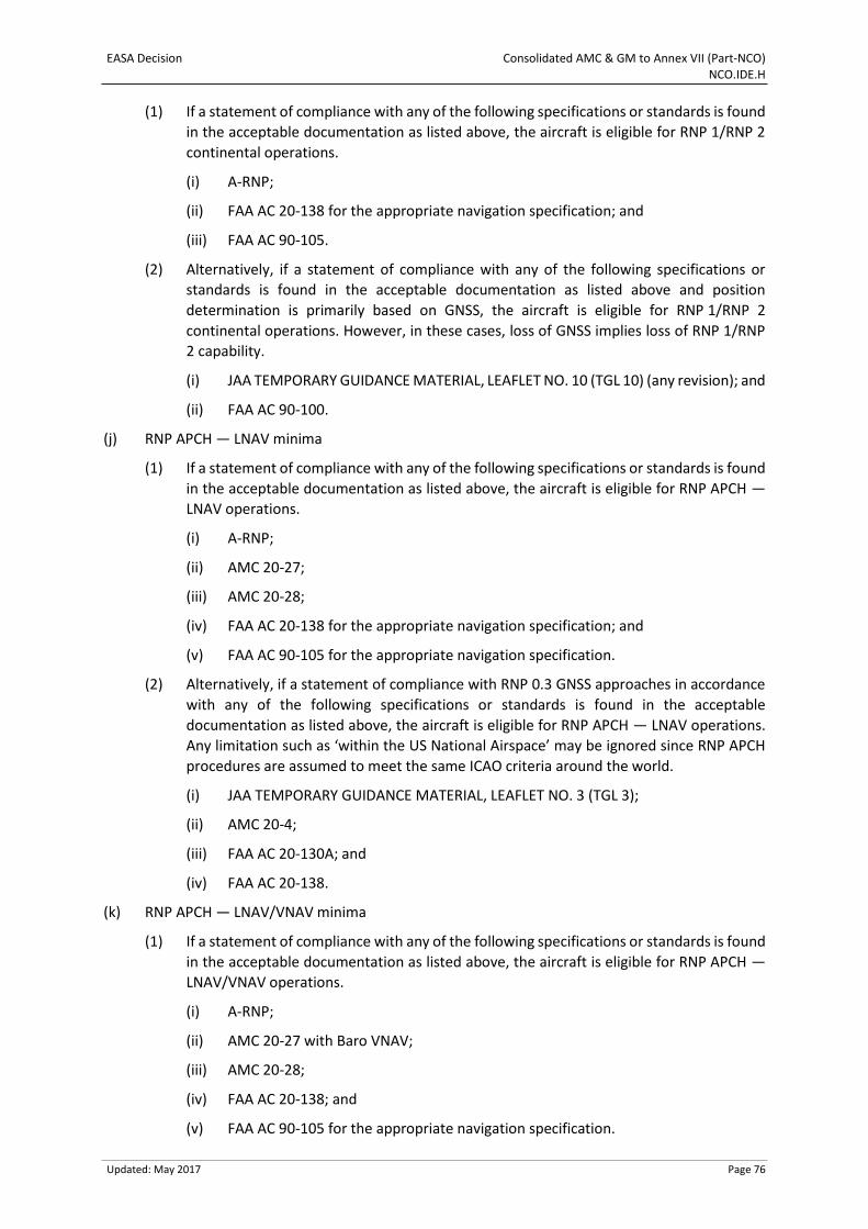
EASA Decision Consolidated AMC & GM to Annex VII (Part-NCO) NCO.IDE.H
Updated: May 2017 Page 76
(1) If a statement of compliance with any of the following specifications or standards is found
in the acceptable documentation as listed above, the aircraft is eligible for RNP 1/RNP 2
continental operations.
(i) A-RNP;
(ii) FAA AC 20-138 for the appropriate navigation specification; and
(iii) FAA AC 90-105.
(2) Alternatively, if a statement of compliance with any of the following specifications or
standards is found in the acceptable documentation as listed above and position
determination is primarily based on GNSS, the aircraft is eligible for RNP 1/RNP 2
continental operations. However, in these cases, loss of GNSS implies loss of RNP 1/RNP
2 capability.
(i) JAA TEMPORARY GUIDANCE MATERIAL, LEAFLET NO. 10 (TGL 10) (any revision); and
(ii) FAA AC 90-100.
(j) RNP APCH — LNAV minima
(1) If a statement of compliance with any of the following specifications or standards is found
in the acceptable documentation as listed above, the aircraft is eligible for RNP APCH —
LNAV operations.
(i) A-RNP;
(ii) AMC 20-27;
(iii) AMC 20-28;
(iv) FAA AC 20-138 for the appropriate navigation specification; and
(v) FAA AC 90-105 for the appropriate navigation specification.
(2) Alternatively, if a statement of compliance with RNP 0.3 GNSS approaches in accordance
with any of the following specifications or standards is found in the acceptable
documentation as listed above, the aircraft is eligible for RNP APCH — LNAV operations.
Any limitation such as ‘within the US National Airspace’ may be ignored since RNP APCH
procedures are assumed to meet the same ICAO criteria around the world.
(i) JAA TEMPORARY GUIDANCE MATERIAL, LEAFLET NO. 3 (TGL 3);
(ii) AMC 20-4;
(iii) FAA AC 20-130A; and
(iv) FAA AC 20-138.
(k) RNP APCH — LNAV/VNAV minima
(1) If a statement of compliance with any of the following specifications or standards is found
in the acceptable documentation as listed above, the aircraft is eligible for RNP APCH —
LNAV/VNAV operations.
(i) A-RNP;
(ii) AMC 20-27 with Baro VNAV;
(iii) AMC 20-28;
(iv) FAA AC 20-138; and
(v) FAA AC 90-105 for the appropriate navigation specification.
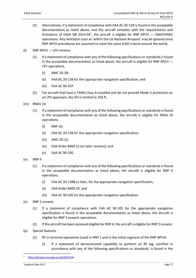
EASA Decision Consolidated AMC & GM to Annex VII (Part-NCO) NCO.IDE.H
Updated: May 2017 Page 77
(2) Alternatively, if a statement of compliance with FAA AC 20-129 is found in the acceptable
documentation as listed above, and the aircraft complies with the requirements and
limitations of EASA SIB 2014-047, the aircraft is eligible for RNP APCH — LNAV/VNAV
operations. Any limitation such as ‘within the US National Airspace’ may be ignored since
RNP APCH procedures are assumed to meet the same ICAO criteria around the world.
(l) RNP APCH — LPV minima
(1) If a statement of compliance with any of the following specifications or standards is found
in the acceptable documentation as listed above, the aircraft is eligible for RNP APCH —
LPV operations.
(i) AMC 20-28;
(ii) FAA AC 20-138 for the appropriate navigation specification; and
(iii) FAA AC 90-107.
(2) For aircraft that have a TAWS Class A installed and do not provide Mode-5 protection on
an LPV approach, the DH is limited to 250 ft.
(m) RNAV 10
(1) If a statement of compliance with any of the following specifications or standards is found
in the acceptable documentation as listed above, the aircraft is eligible for RNAV 10
operations.
(i) RNP 10;
(ii) FAA AC 20-138 for the appropriate navigation specification;
(iii) AMC 20-12;
(iv) FAA Order 8400.12 (or later revision); and
(v) FAA AC 90-105.
(n) RNP 4
(1) If a statement of compliance with any of the following specifications or standards is found
in the acceptable documentation as listed above, the aircraft is eligible for RNP 4
operations.
(i) FAA AC 20-138B or later, for the appropriate navigation specification;
(ii) FAA Order 8400.33; and
(iii) FAA AC 90-105 for the appropriate navigation specification.
(o) RNP 2 oceanic
(1) If a statement of compliance with FAA AC 90-105 for the appropriate navigation
specification is found in the acceptable documentation as listed above, the aircraft is
eligible for RNP 2 oceanic operations.
(2) If the aircraft has been assessed eligible for RNP 4, the aircraft is eligible for RNP 2 oceanic.
(p) Special features
(1) RF in terminal operations (used in RNP 1 and in the initial segment of the RNP APCH)
(i) If a statement of demonstrated capability to perform an RF leg, certified in
accordance with any of the following specifications or standards, is found in the
7 http://ad.easa.europa.eu/ad/2014-04
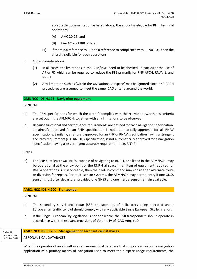
EASA Decision Consolidated AMC & GM to Annex VII (Part-NCO) NCO.IDE.H
Updated: May 2017 Page 78
acceptable documentation as listed above, the aircraft is eligible for RF in terminal
operations:
(A) AMC 20-26; and
(B) FAA AC 20-138B or later.
(ii) If there is a reference to RF and a reference to compliance with AC 90-105, then the
aircraft is eligible for such operations.
(q) Other considerations
(1) In all cases, the limitations in the AFM/POH need to be checked, in particular the use of
AP or FD which can be required to reduce the FTE primarily for RNP APCH, RNAV 1, and
RNP 1.
(2) Any limitation such as ‘within the US National Airspace’ may be ignored since RNP APCH
procedures are assumed to meet the same ICAO criteria around the world.
GM3 NCO.IDE.H.195 Navigation equipment
GENERAL
(a) The PBN specifications for which the aircraft complies with the relevant airworthiness criteria
are set out in the AFM/POH, together with any limitations to be observed.
(b) Because functional and performance requirements are defined for each navigation specification,
an aircraft approved for an RNP specification is not automatically approved for all RNAV
specifications. Similarly, an aircraft approved for an RNP or RNAV specification having a stringent
accuracy requirement (e.g. RNP 0.3 specification) is not automatically approved for a navigation
specification having a less stringent accuracy requirement (e.g. RNP 4).
RNP 4
(c) For RNP 4, at least two LRNSs, capable of navigating to RNP 4, and listed in the AFM/POH, may
be operational at the entry point of the RNP 4 airspace. If an item of equipment required for
RNP 4 operations is unserviceable, then the pilot-in-command may consider an alternate route
or diversion for repairs. For multi-sensor systems, the AFM/POH may permit entry if one GNSS
sensor is lost after departure, provided one GNSS and one inertial sensor remain available.
AMC1 NCO.IDE.H.200 Transponder
GENERAL
(a) The secondary surveillance radar (SSR) transponders of helicopters being operated under
European air traffic control should comply with any applicable Single European Sky legislation.
(b) If the Single European Sky legislation is not applicable, the SSR transponders should operate in
accordance with the relevant provisions of Volume IV of ICAO Annex 10.
AMC1 NCO.IDE.H.205 Management of aeronautical databases
AERONAUTICAL DATABASES
When the operator of an aircraft uses an aeronautical database that supports an airborne navigation
application as a primary means of navigation used to meet the airspace usage requirements, the
AMC1 is applicable as of 01 Jan 2019.
EASA Decision Consolidated AMC & GM to Annex VII (Part-NCO) NCO.IDE.H
Updated: May 2017 Page 79
database provider should be a Type 2 DAT provider certified in accordance with Regulation (EU)
2017/373 or equivalent.
GM1 NCO.IDE.H.205 Management of aeronautical databases
AERONAUTICAL DATABASE APPLICATIONS
The certification of a Type 2 DAT provider in accordance with Regulation (EU) 2017/373 ensures data
integrity and compatibility with the certified aircraft application/equipment.
GM2 NCO.IDE.H.205 Management of aeronautical databases
TIMELY DISTRIBUTION
The operator should distribute current and unaltered aeronautical databases to all aircraft requiring
them in accordance with the validity period of the databases or in accordance with an established
procedure if no validity period is defined.
GM3 NCO.IDE.H.205 Management of aeronautical databases
STANDARDS FOR AERONAUTICAL DATABASES AND DAT PROVIDERS
(a) A ‘Type 2 DAT provider’ is an organisation as defined in Article 2(5)(b) of Regulation (EU)
2017/373.
(b) Equivalent to a certified ‘Type 2 DAT provider’ is defined in any Aviation Safety Agreement
between the European Union and a third country, including any Technical Implementation
Procedures, or any Working Arrangements between EASA and the competent authority of a
third country.
GM1 is applicable as of 01 Jan 2019.
GM2 is applicable as of 01 Jan 2019.
GM3 is applicable as of 01 Jan 2019.
EASA Decision Consolidated AMC & GM to Annex VII (Part-NCO) NCO.IDE.S
Updated: May 2017 Page 80
SECTION 3 Sailplanes
GM1 NCO.IDE.S.100(a) Instruments and equipment — general
APPLICABLE AIRWORTHINESS REQUIREMENTS
The applicable airworthiness requirements for approval of instruments and equipment required by
this Part are the following:
(a) Regulation (EU) No 748/2012 for sailplanes registered in the EU; and
(b) Airworthiness requirements of the State of registry for sailplanes registered outside the EU.
GM1 NCO.IDE.S.100(b) Instruments and equipment — general
REQUIRED INSTRUMENTS AND EQUIPMENT THAT DO NOT NEED TO BE APPROVED IN ACCORDANCE WITH THE APPLICABLE AIRWORTHINESS REQUIREMENTS
The functionality of non-installed instruments and equipment required by this Subpart and that do not
need an equipment approval, as listed in NCO.IDE.S.100(b), should be checked against recognised
industry standards appropriate to the intended purpose. The operator is responsible for ensuring the
maintenance of these instruments and equipment.
GM1 NCO.IDE.S.100(c) Instruments and equipment — general
NOT REQUIRED INSTRUMENTS AND EQUIPMENT THAT DO NOT NEED TO BE APPROVED IN ACCORDANCE WITH THE APPLICABLE AIRWORTHINESS REQUIREMENTS, BUT ARE CARRIED ON A FLIGHT
(a) The provision of this paragraph does not exempt any installed instrument or item of equipment
from complying with the applicable airworthiness requirements. In this case, the installation
should be approved as required in the applicable airworthiness requirements and should comply
with the applicable Certification Specifications.
(b) The failure of additional non-installed instruments or equipment not required by this Part or by
the applicable airworthiness requirements or any applicable airspace requirements should not
adversely affect the airworthiness and/or the safe operation of the sailplane. Examples may be
portable electronic devices carried by crew members or passengers.
AMC1 NCO.IDE.S.115&NCO.IDE.S.120 Operations under VFR & cloud flying — flight and navigational instruments
INTEGRATED INSTRUMENTS
(a) Individual equipment requirements may be met by combinations of instruments or by
integrated flight systems or by a combination of parameters on electronic displays. The
information so available to each required pilot should not be less than that required in the
applicable operational requirements, and the equivalent safety of the installation should be
approved during type certification of the sailplane for the intended type of operation.
EASA Decision Consolidated AMC & GM to Annex VII (Part-NCO) NCO.IDE.S
Updated: May 2017 Page 81
(b) The means of measuring and indicating turn and slip and sailplane attitude may be met by
combinations of instruments, provided that the safeguards against total failure, inherent in the
three separate instruments, are retained.
AMC1 NCO.IDE.S.115(a)(1)&NCO.IDE.S.120(a) Operations under VFR & cloud flying — flight and navigational instruments
MEANS OF MEASURING AND DISPLAYING MAGNETIC HEADING
The means of measuring and displaying magnetic direction should be a magnetic compass or
equivalent.
AMC1 NCO.IDE.S.115(a)(2)&NCO.IDE.S.120(b) Operations under VFR & cloud flying — flight and navigational instruments
MEANS OF MEASURING AND DISPLAYING THE TIME
A means of measuring and displaying the time in hours, minutes and seconds may be a wrist watch
capable of the same functions.
AMC1 NCO.IDE.S.115(a)(3)&NCO.IDE.S.120(c) Operations under VFR & cloud flying — flight and navigational instruments
CALIBRATION OF THE MEANS FOR MEASURING AND DISPLAYING PRESSURE ALTITUDE
(a) The instrument measuring and displaying pressure altitude should be of a sensitive type
calibrated in feet (ft), with a sub-scale setting, calibrated in hectopascals/millibars, adjustable
for any barometric pressure likely to be set during flight.
(b) Calibration in metres (m) is also acceptable.
AMC1 NCO.IDE.S.115(a)(4)&NCO.IDE.S.120(d) Operations under VFR & cloud flying — flight and navigational instruments
CALIBRATION OF THE INSTRUMENT INDICATING AIRSPEED
(a) The instrument indicating airspeed should be calibrated in knots (kt).
(b) Calibration in kilometres per hour (kph) or in miles per hour (mph) is also acceptable.
AMC1 NCO.IDE.S.115(b)(2) Operations under VFR — flight and navigational instruments
SLIP INDICATION
The means of measuring and displaying slip may be a yaw string for operations under VFR.
GM1 NCO.IDE.S.115(b) Operations under VFR — flight and navigational instruments
CONDITIONS WHERE THE SAILPLANE CANNOT BE MAINTAINED IN A DESIRED ATTITUDE WITHOUT REFERENCE TO ONE OR MORE ADDITIONAL INSTRUMENTS
Sailplanes operating in conditions where the sailplane cannot be maintained in a desired attitude
without reference to one or more additional instruments means a condition that is still under VFR
(under VMC) though where there is no external reference such as the natural horizon or a coastline,
that would allow the attitude to be maintained. Such conditions may occur over water, a desert or
EASA Decision Consolidated AMC & GM to Annex VII (Part-NCO) NCO.IDE.S
Updated: May 2017 Page 82
snow-covered areas where the colour of the surface cannot be distinguished from the colour of the
sky and therefore no external reference is available. Cloud flying is not considered to be one of these
conditions.
AMC1 NCO.IDE.S.125 Seats and restraint systems
UPPER TORSO RESTRAINT SYSTEM
(a) A seat belt with upper torso restraint system should have four anchorage points and should
include shoulder straps (two anchorage points) and a seat belt (two anchorage points), which
may be used independently.
(b) A restraint system having five anchorage points is deemed to be compliant to the requirement
for seat belt with upper torso restraint system with four anchorage points.
AMC 1 NCO.IDE.S.130 Supplemental oxygen supply
OXYGEN SUPPLY
The need for oxygen supply, when required by NCO.OP.190, may be met either by means of installed
equipment or portable equipment.
AMC1 NCO.IDE.S.135 Flight over water
MEANS OF ILLUMINATION FOR LIFE-JACKETS
Each life-jacket or equivalent individual flotation device should be equipped with a means of electric
illumination for the purpose of facilitating the location of persons.
RISK ASSESSMENT
(a) When conducting the risk assessment, the pilot-in-command should base his/her decision, as
far as is practicable, on the Implementing Rules and AMCs applicable to the operation of the
sailplane.
(b) The pilot-in-command should, for determining the risk, take the following operating
environment and conditions into account:
(1) sea state;
(2) sea and air temperatures;
(3) the distance from land suitable for making an emergency landing; and
(4) the availability of search and rescue facilities.
GM1 NCO.IDE.S.135(a) Flight over water
SEAT CUSHIONS
Seat cushions are not considered to be flotation devices.
AMC1 NCO.IDE.S.135(b) Flight over water
BATTERIES
(a) All batteries used in ELTs or PLBs should be replaced (or recharged, if the battery is rechargeable)
when the equipment has been in use for more than 1 cumulative hour or in the following cases:
EASA Decision Consolidated AMC & GM to Annex VII (Part-NCO) NCO.IDE.S
Updated: May 2017 Page 83
(1) Batteries specifically designed for use in ELTs and having an airworthiness release
certificate (EASA Form 1 or equivalent) should be replaced (or recharged, if the battery is
rechargeable) before the end of their useful life in accordance with the maintenance
instructions applicable to the ELT.
(2) Standard batteries manufactured in accordance with an industry standard and not having
an airworthiness release certificate (EASA Form 1 or equivalent), when used in ELTs should
be replaced (or recharged, if the battery is rechargeable) when 50 % of their useful life (or
for rechargeable, 50 % of their useful life of charge), as established by the battery
manufacturer, has expired.
(3) All batteries used in PLBs should be replaced (or recharged, if the battery is rechargeable)
when 50 % of their useful life (or for rechargeable, 50 % of their useful life of charge), as
established by the battery manufacturer, has expired.
(4) The battery useful life (or useful life of charge) criteria in (1),(2) and (3) do not apply to
batteries (such as water-activated batteries) that are essentially unaffected during
probable storage intervals.
(b) The new expiry date for a replaced (or recharged) battery should be legibly marked on the
outside of the equipment.
AMC2 NCO.IDE.S.135(b) Flight over water
TYPES OF ELT AND GENERAL TECHNICAL SPECIFICATIONS
(a) The ELT required by this provision should be one of the following:
(1) Automatic fixed (ELT(AF)). An automatically activated ELT that is permanently attached to
an aircraft and is designed to aid SAR teams in locating the crash site.
(2) Automatic portable (ELT(AP)). An automatically activated ELT that is rigidly attached to an
aircraft before a crash, but is readily removable from the aircraft after a crash. It functions
as an ELT during the crash sequence. If the ELT does not employ an integral antenna, the
aircraft-mounted antenna may be disconnected and an auxiliary antenna (stored on the
ELT case) attached to the ELT. The ELT can be tethered to a survivor or a life-raft. This type
of ELT is intended to aid SAR teams in locating the crash site or survivor(s).
(3) Automatic Deployable (ELT(AD)). An ELT that is rigidly attached to the aircraft before the
crash and that is automatically ejected, deployed and activated by an impact, and, in some
cases, also by hydrostatic sensors. Manual deployment is also provided. This type of ELT
should float in water and is intended to aid SAR teams in locating the crash site.
(4) Survival ELT (ELT(S)). An ELT that is removable from an aircraft, stowed so as to facilitate
its ready use in an emergency and manually activated by a survivor. An ELT(S) may be
activated manually or automatically (e.g. by water activation). It should be designed either
to be tethered to a life-raft or a survivor.
(b) To minimise the possibility of damage in the event of crash impact, the automatic ELT should be
rigidly fixed to the aircraft structure, as far aft as is practicable, with its antenna and connections
arranged so as to maximise the probability of the signal being transmitted after a crash.
(c) Any ELT carried should operate in accordance with the relevant provisions of ICAO Annex 10,
Volume III, and should be registered with the national agency responsible for initiating search
and rescue or other nominated agency.
EASA Decision Consolidated AMC & GM to Annex VII (Part-NCO) NCO.IDE.S
Updated: May 2017 Page 84
AMC3 NCO.IDE.S.135(b) Flight over water
PLB TECHNICAL SPECIFICATIONS
(a) A personal locator beacon (PLB) should have a built-in GNSS receiver with a cosmicheskaya
sistyema poiska avariynich sudov — search and rescue satellite-aided tracking (COSPAS-SARSAT)
type approval number. However, devices with a COSPAS-SARSAT number belonging to series
700 are excluded as this series of numbers identifies the special-use beacons not meeting all the
technical requirements and all the tests specified by COSPAS-SARSAT.
(b) Any PLB carried should be registered with the national agency responsible for initiating search
and rescue or other nominated agency.
AMC4 NCO.IDE.S.135(b) Flight over water
BRIEFING ON PLB USE
When a PLB is carried by a passenger, he/she should be briefed on its characteristics and use by the
pilot-in-command before the flight.
GM1 NCO.IDE.S.135(b) Flight over water
TERMINOLOGY
(a) An ELT is a generic term describing equipment that broadcasts distinctive signals on designated
frequencies and, depending on application, may be activated by impact or may be manually
activated.
(b) A PLB is an emergency beacon other than an ELT that broadcasts distinctive signals on
designated frequencies, is standalone, portable and is manually activated by the survivors.
AMC1 NCO.IDE.S.140 Survival equipment
GENERAL
Sailplanes operated across land areas in which search and rescue would be especially difficult should
be equipped with the following:
(a) signalling equipment to make the distress signals;
(b) at least one ELT(S) or a PLB; and
(c) additional survival equipment for the route to be flown taking account of the number of persons
on board.
AMC2 NCO.IDE.S.140 Survival equipment
ADDITIONAL SURVIVAL EQUIPMENT
(a) The following additional survival equipment should be carried when required:
(1) 500 ml of water;
(2) one knife;
(3) first-aid equipment; and
(4) one set of air/ground codes.
EASA Decision Consolidated AMC & GM to Annex VII (Part-NCO) NCO.IDE.S
Updated: May 2017 Page 85
(b) If any item of equipment contained in the above list is already carried on board the sailplane in
accordance with another requirement, there is no need for this to be duplicated.
GM1 NCO.IDE.S.140 Survival equipment
SIGNALLING EQUIPMENT
The signalling equipment for making distress signals is described in ICAO Annex 2, Rules of the Air.
GM2 NCO.IDE.S.140 Survival equipment
AREAS IN WHICH SEARCH AND RESCUE WOULD BE ESPECIALLY DIFFICULT
The expression ‘areas in which search and rescue would be especially difficult’ should be interpreted,
in this context, as meaning:
(a) areas so designated by the authority responsible for managing search and rescue; or
(b) areas that are largely uninhabited and where:
(1) the authority referred to in (a) has not published any information to confirm whether
search and rescue would be or would not be especially difficult; and
(2) the authority referred to in (a) does not, as a matter of policy, designate areas as being
especially difficult for search and rescue.
GM1 NCO.IDE.S.150 Navigation equipment
APPLICABLE AIRSPACE REQUIREMENTS
For sailplanes being operated under European air traffic control, the applicable airspace requirements
include the Single European Sky legislation.
AMC1 NCO.IDE.S.155 Transponder
GENERAL
(a) The secondary surveillance radar (SSR) transponders of sailplanes being operated under
European air traffic control should comply with any applicable Single European Sky legislation.
(b) If the Single European Sky legislation is not applicable, the SSR transponders should operate in
accordance with the relevant provisions of Volume IV of ICAO Annex 10.
EASA Decision Consolidated AMC & GM to Annex VII (Part-NCO) NCO.IDE.B
Updated: May 2017 Page 86
SECTION 4 Balloons
GM1 NCO.IDE.B.100(a) Instruments and equipment — general
APPLICABLE AIRWORTHINESS REQUIREMENTS
The applicable airworthiness requirements for approval of instruments and equipment required by
this Part are the following:
(a) Regulation (EU) No 748/2012 for balloons registered in the EU; and
(b) Airworthiness requirements of the state of registry for balloons registered outside the EU.
GM1 NCO.IDE.B.100(b) Instruments and equipment — general
REQUIRED INSTRUMENTS AND EQUIPMENT THAT DO NOT NEED TO BE APPROVED IN ACCORDANCE WITH THE APPLICABLE AIRWORTHINESS REQUIREMENTS
The functionality of non-installed instruments and equipment required by this Subpart and that do not
need an equipment approval, as listed in NCO.IDE.B.100(b), should be checked against recognised
industry standards appropriate to the intended purpose. The operator is responsible for ensuring the
maintenance of these instruments and equipment.
GM1 NCO.IDE.B.100(c) Instruments and equipment — general
NOT REQUIRED INSTRUMENTS AND EQUIPMENT THAT DO NOT NEED TO BE APPROVED IN ACCORDANCE WITH THE APPLICABLE AIRWORTHINESS REQUIREMENTS, BUT ARE CARRIED ON A FLIGHT
(a) The provision of this paragraph does not exempt any installed instrument or item of equipment
from complying with the applicable airworthiness requirements. In this case, the installation
should be approved as required in the applicable airworthiness requirements and should comply
with the applicable Certification Specifications.
(b) The failure of additional non-installed instruments or equipment not required by this Part or by
the applicable airworthiness requirements or any applicable airspace requirements should not
adversely affect the airworthiness and/or the safe operation of the balloon. Examples may be
portable electronic devices carried by crew members or passengers.
AMC1 NCO.IDE.B.110 Operating lights
ANTI-COLLISION LIGHTS
An acceptable means of compliance is the anti-collision light required for free manned balloons
certified for VFR at night in accordance with CS 31HB/GB.
ILLUMINATION FOR INSTRUMENTS AND EQUIPMENT
A means of providing adequate illumination to instruments and equipment essential to the safe
operation of the balloon may be an independent portable light.
EASA Decision Consolidated AMC & GM to Annex VII (Part-NCO) NCO.IDE.B
Updated: May 2017 Page 87
AMC1 NCO.IDE.B.115(a) Operations under VFR — flight and navigational instruments
MEANS OF DISPLAYING DRIFT DIRECTION
The drift direction may be determined by using a map and reference to visual landmarks.
AMC1 NCO.IDE.B.115(b)(1) Operations under VFR — flight and navigational instruments
MEANS OF MEASURING AND DISPLAYING THE TIME
A means of measuring and displaying the time in hours, minutes and seconds may be a wrist watch
capable of the same functions.
GM1 NCO.IDE.B.115(b)(2) Operations under VFR — flight and navigational instruments
MEANS OF MEASURING AND DISPLAYING VERTICAL SPEED
The necessity of a vertical speed indicator depends on the balloon design. Some envelope shapes have
a high drag and will therefore not develop a high ascent/descent speed. Such balloons usually do not
require a vertical speed indicator. More slender envelope shapes such as special shape balloons may
have a significantly lower drag. Their ascent/descent speed is usually limited to a certain value so that
controllability of the balloon is maintained. To be able to stay within this limitation of the AFM, a
vertical speed indicator is required for such balloons.
GM1 NCO.IDE.B.115(b)(3) Operations under VFR — flight and navigational instruments and associated equipment
MEANS OF MEASURING AND DISPLAYING PRESSURE ALTITUDE
A means of measuring and displaying pressure altitude is needed when required by ATC, or by
Regulation (EU) 923/2012, or when altitude needs to be checked for flights where oxygen is used, or
the limitations in the AFM require to limit altitude and/or rate of climb/descent.
AMC1 NCO.IDE.B.120 First-aid kit
CONTENT OF FIRST-AID KITS
(a) First-aid kits should be equipped with appropriate and sufficient medications and
instrumentation. However, these kits should be amended by the operator according to the
characteristics of the operation (scope of operation, flight duration, number and demographics
of passengers, etc.).
(b) The following should be included in the FAKs:
(1) bandages (assorted sizes),
(2) burns dressings (large and small),
(3) wound dressings (large and small),
(4) adhesive dressings (assorted sizes),
(5) antiseptic wound cleaner,
(6) safety scissors,
(7) disposable gloves.
EASA Decision Consolidated AMC & GM to Annex VII (Part-NCO) NCO.IDE.B
Updated: May 2017 Page 88
AMC2 NCO.IDE.B.120 First-aid kit
MAINTENANCE OF FIRST-AID KIT
To be kept up-to-date, first-aid kits should be:
(a) inspected periodically to confirm, to the extent possible, that contents are maintained in the
condition necessary for their intended use;
(b) replenished at regular intervals, in accordance with instructions contained on their labels, or as
circumstances warrant; and
(c) replenished after use in-flight at the first opportunity where replacement items are available.
AMC1 NCO.IDE.B.125 Hand fire extinguishers
CERTIFICATION SPECIFICATIONS
The applicable Certification Specification for hot-air balloons should be CS-31HB or equivalent.
AMC1 NCO.IDE.B.130 Flight over water
MEANS OF ILLUMINATION FOR LIFE-JACKETS
Each life-jacket or equivalent individual flotation device should be equipped with a means of electric
illumination for the purpose of facilitating the location of persons.
RISK ASSESSMENT
(a) When conducting the risk assessment, the pilot-in-command should base his/her decision, as
far as is practicable, on the Implementing Rules and AMCs applicable to the operation of the
balloon.
(b) The pilot-in-command should, for determining the risk, take the following operating
environment and conditions into account:
(1) sea state;
(2) sea and air temperatures;
(3) the distance from land suitable for making an emergency landing; and
(4) the availability of search and rescue facilities.
AMC1 NCO.IDE.B.130(b) Flight over water
BATTERIES
(a) All batteries used in ELTs or PLBs should be replaced (or recharged, if the battery is rechargeable)
when the equipment has been in use for more than 1 cumulative hour or in the following cases:
(1) Batteries specifically designed for use in ELTs and having an airworthiness release
certificate (EASA Form 1 or equivalent) should be replaced (or recharged, if the battery is
rechargeable) before the end of their useful life in accordance with the maintenance
instructions applicable to the ELT.
(2) Standard batteries manufactured in accordance with an industry standard and not having
an airworthiness release certificate (EASA Form 1 or equivalent), when used in ELTs should
be replaced (or recharged, if the battery is rechargeable) when 50 % of their useful life (or
EASA Decision Consolidated AMC & GM to Annex VII (Part-NCO) NCO.IDE.B
Updated: May 2017 Page 89
for rechargeable, 50 % of their useful life of charge), as established by the battery
manufacturer, has expired.
(3) All batteries used in PLBs should be replaced (or recharged, if the battery is rechargeable)
when 50 % of their useful life (or for rechargeable, 50 % of their useful life of charge), as
established by the battery manufacturer, has expired.
(4) The battery useful life (or useful life of charge) criteria in (1),(2) and (3) do not apply to
batteries (such as water-activated batteries) that are essentially unaffected during
probable storage intervals.
(b) The new expiry date for a replaced (or recharged) battery should be legibly marked on the
outside of the equipment.
AMC2 NCO.IDE.B.130(b) Flight over water
TYPES OF ELT AND GENERAL TECHNICAL SPECIFICATIONS
(a) The ELT required by this provision should be one of the following:
(1) Automatic fixed (ELT(AF)). An automatically activated ELT that is permanently attached to
an aircraft and is designed to aid SAR teams in locating the crash site.
(2) Automatic portable (ELT(AP)). An automatically activated ELT that is rigidly attached to an
aircraft before a crash, but is readily removable from the aircraft after a crash. It functions
as an ELT during the crash sequence. If the ELT does not employ an integral antenna, the
aircraft-mounted antenna may be disconnected and an auxiliary antenna (stored on the
ELT case) attached to the ELT. The ELT can be tethered to a survivor or a life-raft. This type
of ELT is intended to aid SAR teams in locating the crash site or survivor(s).
(3) Automatic deployable (ELT(AD)). An ELT that is rigidly attached to the aircraft before the
crash and which is automatically ejected, deployed and activated by an impact, and, in
some cases, also by hydrostatic sensors. Manual deployment is also provided. This type
of ELT should float in water and is intended to aid SAR teams in locating the crash site.
(4) Survival ELT (ELT(S)). An ELT that is removable from an aircraft, stowed so as to facilitate
its ready use in an emergency and manually activated by a survivor. An ELT(S) may be
activated manually or automatically (e.g. by water activation). It should be designed either
to be tethered to a life-raft or a survivor.
(b) To minimise the possibility of damage in the event of crash impact, the automatic ELT should be
rigidly fixed to the aircraft structure, as far aft as is practicable, with its antenna and connections
arranged so as to maximise the probability of the signal being transmitted after a crash.
(c) Any ELT carried should operate in accordance with the relevant provisions of ICAO Annex 10,
Volume III, and should be registered with the national agency responsible for initiating search
and rescue or other nominated agency.
AMC3 NCO.IDE.B.130(b) Flight over water
PLB TECHNICAL SPECIFICATIONS
(a) A personal locator beacon (PLB) should have a built-in GNSS receiver with a cosmicheskaya
sistyema poiska avariynich sudov — search and rescue satellite-aided tracking (COSPAS-SARSAT)
type approval number. However, devices with a COSPAS-SARSAT number belonging to series
700 are excluded as this series of numbers identifies the special-use beacons not meeting all the
technical requirements and all the tests specified by COSPAS-SARSAT.
EASA Decision Consolidated AMC & GM to Annex VII (Part-NCO) NCO.IDE.B
Updated: May 2017 Page 90
(b) Any PLB carried should be registered with the national agency responsible for initiating search
and rescue or other nominated agency.
AMC4 NCO.IDE.B.130(b) Flight over water
BRIEFING ON PLB USE
When a PLB is carried by a passenger, he/she should be briefed on its characteristics and use by the
pilot-in-command before the flight.
GM1 NCO.IDE.B.130(b) Flight over water
TERMINOLOGY
(a) An ELT is a generic term describing equipment that broadcasts distinctive signals on designated
frequencies and, depending on application, may be activated by impact or may be manually
activated.
(b) A PLB is an emergency beacon other than an ELT that broadcasts distinctive signals on
designated frequencies, is standalone, portable and is manually activated by the survivors.
GM1 NCO.IDE.B.130(d) Survival equipment
SIGNALLING EQUIPMENT
The signalling equipment for making distress signals is described in ICAO Annex 2, Rules of the Air.
AMC1 NCO.IDE.B.135 Survival equipment
GENERAL
Balloons operated across land areas in which search and rescue would be especially difficult should be
equipped with the following:
(a) signalling equipment to make the distress signals;
(b) at least one ELT(S) or a PLB; and
(c) additional survival equipment for the route to be flown taking account of the number of persons
on board.
AMC2 NCO.IDE.B.135 Survival equipment
ADDITIONAL SURVIVAL EQUIPMENT
(a) The following additional survival equipment should be carried when required:
(1) 500 ml of water for each four, or fraction of four, persons on board;
(2) one knife;
(3) first-aid equipment; and
(4) one set of air/ground codes.
(b) If any item of equipment contained in the above list is already carried on board the balloon in
accordance with another requirement, there is no need for this to be duplicated.
EASA Decision Consolidated AMC & GM to Annex VII (Part-NCO) NCO.IDE.B
Updated: May 2017 Page 91
GM1 NCO.IDE.B.135 Survival equipment
AREAS IN WHICH SEARCH AND RESCUE WOULD BE ESPECIALLY DIFFICULT
The expression ‘areas in which search and rescue would be especially difficult’ should be interpreted,
in this context, as meaning:
(a) areas so designated by the authority responsible for managing search and rescue; or
(b) areas that are largely uninhabited and where:
(1) the authority referred to in (a) has not published any information to confirm whether
search and rescue would be or would not be especially difficult; and
(2) the authority referred to in (a) does not, as a matter of policy, designate areas as being
especially difficult for search and rescue.
AMC1 NCO.IDE.B.140(b)(3) Miscellaneous equipment
FIRE BLANKET
A fire blanket should comply with EN 1869 or equivalent. The size should be at least 1.5 m x 2 m.
Smaller sizes are not recommended as they cannot sufficiently cover the source of developing propane
fire.
AMC1 NCO.IDE.B.140 (c)(1) Miscellaneous equipment
KNIFE
The knife, hook knife or equivalent, should be capable of cutting any control line or handling rope that
is accessible to the pilot-in-command or a crew member from the basket.
GM1 NCO.IDE.B.145 Radio communication equipment
APPLICABLE AIRSPACE REQUIREMENTS
For balloons being operated under European air traffic control, the applicable airspace requirements
include the Single European Sky legislation.
AMC1 NCO.IDE.B.150 Transponder
GENERAL
(a) The secondary surveillance radar (SSR) transponders of balloons being operated under European
air traffic control should comply with any applicable Single European Sky legislation.
(b) If the Single European Sky legislation is not applicable, the SSR transponders should operate in
accordance with the relevant provisions of Volume IV of ICAO Annex 10.
EASA Decision Consolidated AMC & GM to Annex VII (Part-NCO) NCO.SPEC
Updated: May 2017 Page 92
SUBPART E: SPECIFIC REQUIREMENTS
SECTION 1 General
AMC1 NCO.SPEC.100 Scope
CRITERIA
The pilot-in-command should consider the following criteria to determine whether an activity falls
within the scope of specialised operations:
(a) the aircraft is flown close to the surface to fulfil the mission;
(b) abnormal manoeuvres are performed;
(c) special equipment is necessary to fulfil the mission and which affects the manoeuvrability of the
aircraft;
(d) substances are released from the aircraft during the flight where these substances are either
harmful or affect the manoeuvrability of the aircraft;
(e) external loads or goods are lifted or towed; or
(f) persons enter or leave the aircraft during flight.
GM1 NCO.SPEC.100 Scope
LIST OF SPECIALISED OPERATIONS
(a) Specialised operations include the following activities:
(1) helicopter external loads operations;
(2) helicopter survey operations;
(3) human external cargo operations;
(4) parachute operations and skydiving;
(5) agricultural flights;
(6) aerial photography flights;
(7) glider towing;
(8) aerial advertising flights;
(9) calibration flights;
(10) construction work flights, including stringing power line operations, clearing saw
operations;
(11) oil spill work;
(12) avalanche mining operations;
(13) survey operations, including aerial mapping operations, pollution control activity;
(14) news media flights, television and movie flights;
EASA Decision Consolidated AMC & GM to Annex VII (Part-NCO) NCO.SPEC
Updated: May 2017 Page 93
(15) special events flights, including such as flying display, competition flights;
(16) aerobatic flights;
(17) animal herding and rescue flights and veterinary dropping flights;
(18) maritime funeral operations;
(19) scientific research flights (other than those under Annex II of Regulation 216/2008); and
(20) cloud seeding.
(b) For other operations, the pilot-in-command can apply the criteria specified in AMC1
NCO.SPEC.100 to determine whether an activity falls within the scope of specialised operations.
GM1 NCO.SPEC.105 Checklist
DEVELOPMENT OF CHECKLISTS
For developing the checklist, the pilot-in-command should duly take into account at least the following
items:
(a) nature and complexity of the activity:
(1) the nature of the flight and the risk exposure, e.g. low height;
(2) the complexity of the activity taking into account the necessary pilot skills and level of
experience, ground support, safety and individual protective equipment;
(3) the operational environment and geographical area, e.g., congested hostile environment,
mountainous areas, sea areas, or desert areas;
(4) the result of the risk assessment and evaluation;
(b) aircraft and equipment:
(1) the category of aircraft to be used for the activity should be indicated, e.g.
helicopter/aeroplane, single/multi-engined;
(2) all equipment required for the activity should be listed;
(c) crew members:
(1) crew composition;
(2) minimum crew experience and training provisions; and
(3) recency provisions;
(d) task specialists:
(1) description of the task specialists’ function(s)
(2) minimum crew experience and training provisions; and
(3) recency provisions;
(4) briefing;
(e) aircraft performance:
this chapter should detail the specific performance requirements to be applied, in order to
ensure an adequate power margin;
(f) normal procedures and emergency procedures:
(1) operating procedures for the flight crew, including the coordination with task specialists;
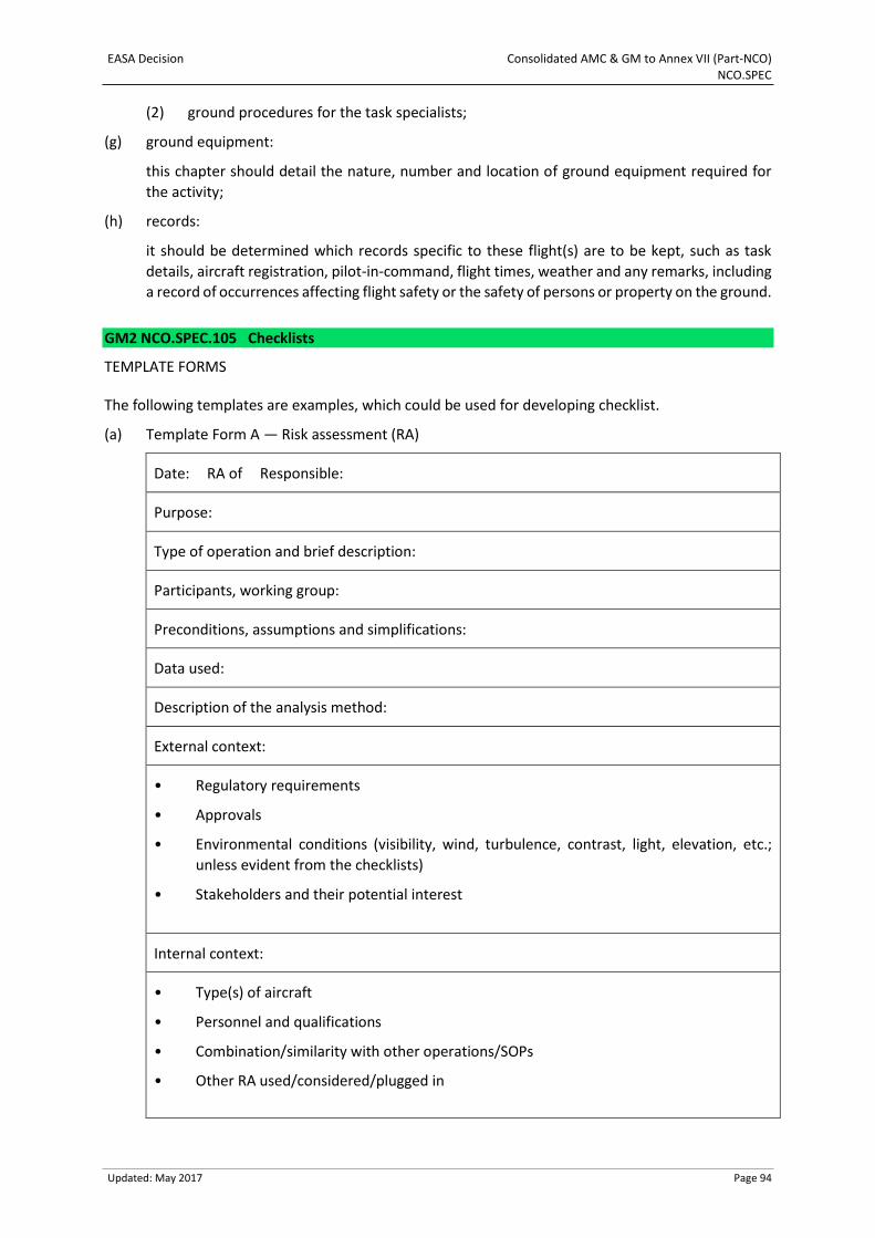
EASA Decision Consolidated AMC & GM to Annex VII (Part-NCO) NCO.SPEC
Updated: May 2017 Page 94
(2) ground procedures for the task specialists;
(g) ground equipment:
this chapter should detail the nature, number and location of ground equipment required for
the activity;
(h) records:
it should be determined which records specific to these flight(s) are to be kept, such as task
details, aircraft registration, pilot-in-command, flight times, weather and any remarks, including
a record of occurrences affecting flight safety or the safety of persons or property on the ground.
GM2 NCO.SPEC.105 Checklists
TEMPLATE FORMS
The following templates are examples, which could be used for developing checklist.
(a) Template Form A — Risk assessment (RA)
Date: RA of Responsible:
Purpose:
Type of operation and brief description:
Participants, working group:
Preconditions, assumptions and simplifications:
Data used:
Description of the analysis method:
External context:
• Regulatory requirements
• Approvals
• Environmental conditions (visibility, wind, turbulence, contrast, light, elevation, etc.;
unless evident from the checklists)
• Stakeholders and their potential interest
Internal context:
• Type(s) of aircraft
• Personnel and qualifications
• Combination/similarity with other operations/SOPs
• Other RA used/considered/plugged in
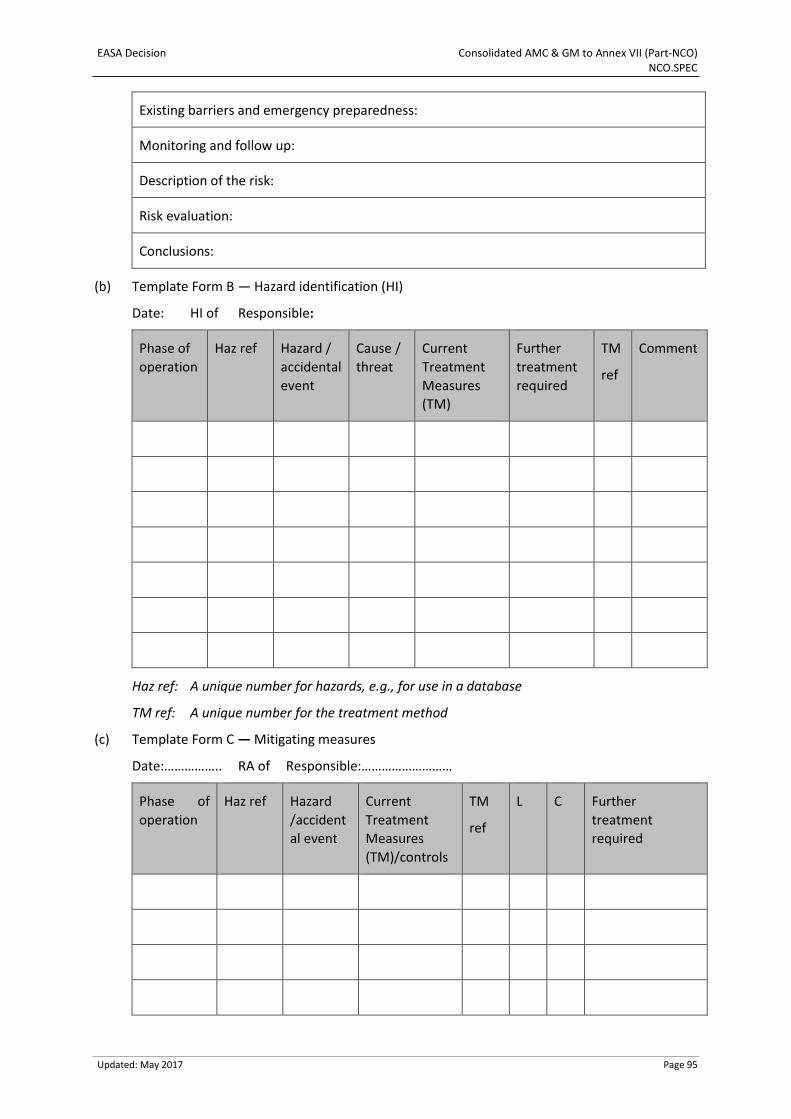
EASA Decision Consolidated AMC & GM to Annex VII (Part-NCO) NCO.SPEC
Updated: May 2017 Page 95
Existing barriers and emergency preparedness:
Monitoring and follow up:
Description of the risk:
Risk evaluation:
Conclusions:
(b) Template Form B — Hazard identification (HI)
Date: HI of Responsible:
Phase of
operation
Haz ref Hazard /
accidental
event
Cause /
threat
Current
Treatment
Measures
(TM)
Further
treatment
required
TM
ref
Comment
Haz ref: A unique number for hazards, e.g., for use in a database
TM ref: A unique number for the treatment method
(c) Template Form C — Mitigating measures
Date:…………….. RA of Responsible:………………………
Phase of
operation
Haz ref Hazard
/accident
al event
Current
Treatment
Measures
(TM)/controls
TM
ref
L C Further
treatment
required
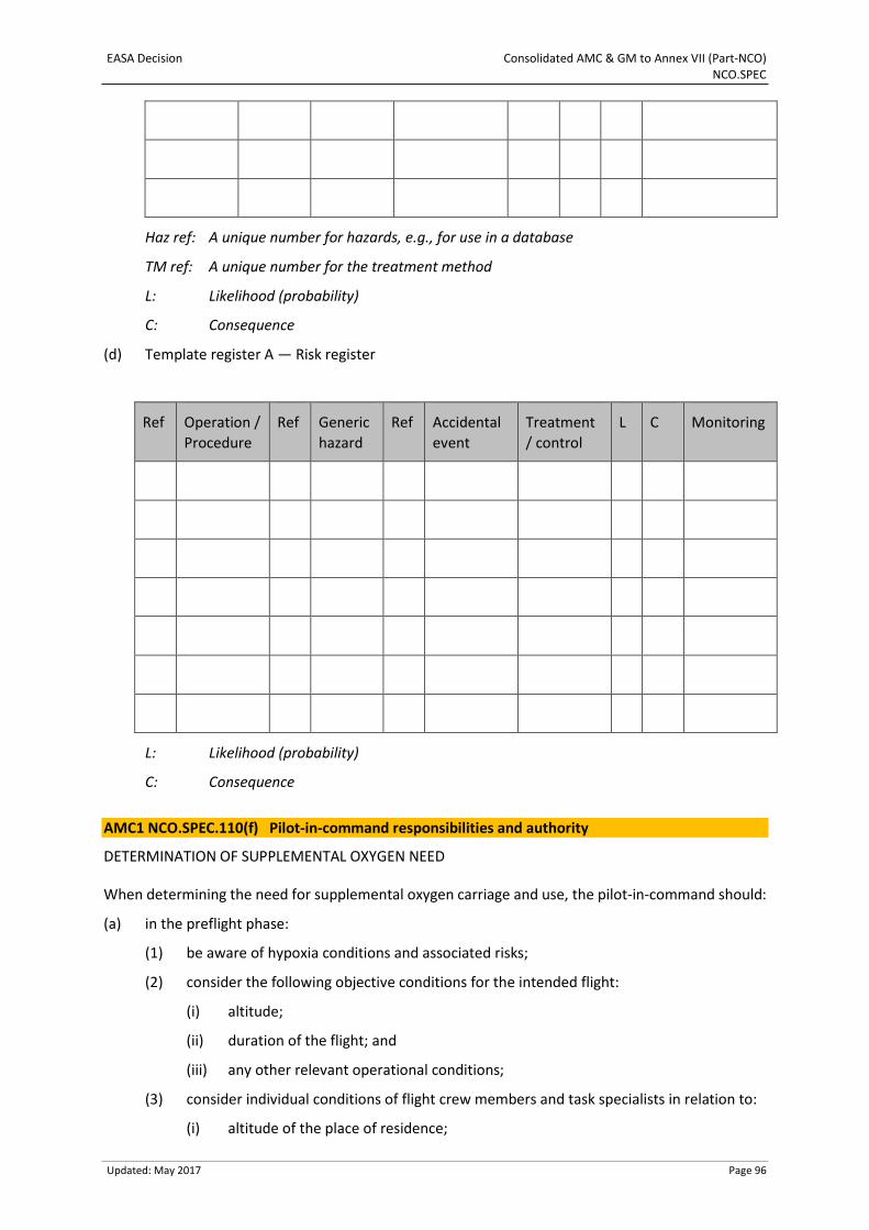
EASA Decision Consolidated AMC & GM to Annex VII (Part-NCO) NCO.SPEC
Updated: May 2017 Page 96
Haz ref: A unique number for hazards, e.g., for use in a database
TM ref: A unique number for the treatment method
L: Likelihood (probability)
C: Consequence
(d) Template register A — Risk register
Ref Operation /
Procedure
Ref Generic
hazard
Ref Accidental
event
Treatment
/ control
L C Monitoring
L: Likelihood (probability)
C: Consequence
AMC1 NCO.SPEC.110(f) Pilot-in-command responsibilities and authority
DETERMINATION OF SUPPLEMENTAL OXYGEN NEED
When determining the need for supplemental oxygen carriage and use, the pilot-in-command should:
(a) in the preflight phase:
(1) be aware of hypoxia conditions and associated risks;
(2) consider the following objective conditions for the intended flight:
(i) altitude;
(ii) duration of the flight; and
(iii) any other relevant operational conditions;
(3) consider individual conditions of flight crew members and task specialists in relation to:
(i) altitude of the place of residence;
EASA Decision Consolidated AMC & GM to Annex VII (Part-NCO) NCO.SPEC
Updated: May 2017 Page 97
(ii) smoking;
(iii) experience in flights at high altitudes;
(iv) actual medical conditions and medications;
(v) age;
(vi) disabilities; and
(vii) any other relevant factor that may be detected, or reported by the person; and
(4) when relevant, ensure that all flight crew members and task specialists are briefed on
hypoxia conditions and symptoms, as well as on the usage of supplemental oxygen
equipment.
(b) during flight:
(1) monitor for early symptoms of hypoxia conditions; and
(2) if detecting early symptoms of hypoxia conditions:
(i) consider to return to a safe altitude, and
(ii) ensure that supplemental oxygen is used, if available.
GM1 NCO.SPEC.110(f) Pilot-in-command responsibilities and authority
DETERMINATION OF SUPPLEMENTAL OXYGEN NEED
(a) The responsibility of the pilot-in-command for safety of all persons on board, as required by
NCO.GEN.105(a)(1), includes the determination of need for supplemental oxygen use.
(b) The altitudes above which NCO.SPEC.110(f) requires oxygen to be available and used are
applicable to those cases when the pilot-in-command cannot determine the need for
supplemental oxygen. However, if the pilot-in-command is able to make this determination,
he/she may elect in the interest of safety to require oxygen also for operations at or below such
altitudes.
(c) The pilot-in-command should be aware that flying below altitudes mentioned in
NCO.SPEC.110(f) does not provide absolute protection against hypoxia symptoms, should
individual conditions and aptitudes be prevalent.
GM2 NCO.SPEC.110(f) Pilot-in-command responsibilities and authority
DETERMINATION OF OXYGEN NEED — BEFORE FLIGHT
Detailed information and guidance on hypoxia conditions and symptoms, content of the briefing on
hypoxia and assessment of individual conditions may be found in the EASA leaflet ‘Hypoxia’.
DETERMINATION OF OXYGEN NEED — IN FLIGHT
Several methods for monitoring hypoxia early symptoms may be used and some methods may be
aided by personal equipment, such as finger-mounted pulse oximeters. Detailed information and
guidance on entering hypoxia conditions, on hypoxia symptoms early detection, and on use of personal
equipment such as finger-mounted pulse oximeters or equivalent may be found in the EASA leaflet
‘Hypoxia’.
EASA Decision Consolidated AMC & GM to Annex VII (Part-NCO) NCO.SPEC
Updated: May 2017 Page 98
AMC1 NCO.SPEC.125 Safety briefing
TASK SPECIALISTS
(a) Safety briefings should ensure that task specialists are familiar with all aspects of the operation,
including their responsibilities.
(b) Such briefings should include, as appropriate:
(1) behaviour on the ground and in-flight, including emergency procedures;
(2) procedures for boarding and disembarking;
(3) procedures for loading and unloading the aircraft;
(4) use of doors in normal and emergency operations;
(5) use of communication equipment and hand signals;
(6) precautions in case of a landing on sloping ground; and
(7) in addition to the items listed from (b)(1) to (b)(6) before take-off:
(i) location of emergency exits;
(ii) restrictions regarding smoking;
(iii) restrictions regarding the use of portable electronic equipment; and
(iv) stowage of tools and hand baggage.
(c) Briefings may be given as a verbal presentation or by issuing the appropriate procedures and
instructions in written form. Before commencement of the flight, their understanding should be
confirmed.
GM1 NCO.SPEC.175(c) Performance and operating criteria — helicopters
GENERAL
(a) Even when the surface allows a hover in ground effect (HIGE), the likelihood of, for example,
dust or blowing snow may necessitate hover out of ground effect (HOGE) performance.
(b) Wind conditions on some sites, particularly downdraft in mountainous areas, may require a
reduction in the helicopter mass in order to ensure that an out of ground effect hover can be
achieved at the operational site in the conditions prevailing.
EASA Decision Consolidated AMC & GM to Annex VII (Part-NCO) NCO.SPEC.HESLO
Updated: May 2017 Page 99
SECTION 2 Helicopter external sling load operations (HESLO)
GM1 NCO.SPEC.HESLO.100 Checklist
REFERENCES
The following references to the AMC and GM of Annex VIII (Part-SPO) provide further guidance for the
development of checklists.
(a) AMC1 SPO.SPEC.HESLO.100 provides a generic framework for the development of standard
operating procedures (SOP) for HESLO operations. This AMC can be regarded as a good practice
example for developing the checklist for HESLO operations.
(b) GM1 SPO.SPEC.HESLO.100 provides guidance for initial pilot training for HESLO types 1, 2, 3 and
4.
EASA Decision Consolidated AMC & GM to Annex VII (Part-NCO) NCO.SPEC.HEC
Updated: May 2017 Page 100
SECTION 3 Human external cargo operations (HEC)
GM1 NCO.SPEC.HEC.100 Checklist
REFERENCES
AMC1 SPO.SPEC.HEC.100 of Annex VIII (Part-SPO) provides a generic framework for the development
of SOP for HEC operations. This AMC can be regarded as a good practice example for developing the
checklist for HEC operations.