acceptable means of compliance (amc) and guidance material ... to ed decision 2014-018-r... ·...
TRANSCRIPT

Annex to ED Decision 2014/018/R
Page 1 of 184
European Aviation Safety Agency
Acceptable Means of Compliance
(AMC)
and Guidance Material (GM)
to
Part-SPO
Initial issue1
24 April 2014
1 For the date of entry into force of this issue, refer to Decision 2014/018/R in the Official
Publication of the Agency.
AMC/GM TO ANNEX VIII (PART-SPO)
TABLE OF CONTENTS
Page 2 of 184
Table of contents
AMC/GM to Annex VIII (Part-SPO) .......................................................................... 21
AMC1 SPO.GEN.005 Scope ............................................................................. 21
CRITERIA .............................................................................................. 21
GM1 SPO.GEN.005 Scope ............................................................................... 21
LIST OF SPECIALISED OPERATIONS ......................................................... 21
Subpart A — General requirements ........................................................................ 23
GM1 SPO.GEN.105(e)(2) Crew member responsibilities ..................................... 23
GENERAL .............................................................................................. 23
GM1 SPO.GEN.107 Pilot-in-command responsibilities and authority ..................... 23
GENERAL .............................................................................................. 23
GM1 SPO.GEN.107(a)(8) Pilot-in-command responsibilities and authority ............ 24
RECORDING UTILISATION DATA .............................................................. 24
AMC1 SPO.GEN.107(c) Pilot-in-command responsibilities and authority............... 24
REPORTING OF HAZARDOUS FLIGHT CONDITIONS .................................... 24
GM1 SPO.GEN.108(c) Pilot-in-command responsibilities and authority —
balloons ......................................................................................................... 24
PROTECTIVE CLOTHING.......................................................................... 24
AMC1 SPO.GEN.107(e) Pilot-in-command responsibilities and authority —
balloons ......................................................................................................... 24
VIOLATION REPORTING .......................................................................... 24
GM1 SPO.GEN.120(b)(4) Taxiing of aeroplanes ................................................. 25
SKILLS AND KNOWLEDGE ....................................................................... 25
GM1 SPO.GEN.125 Rotor engagement ............................................................. 25
INTENT OF THE RULE ............................................................................. 25
GM1 SPO.GEN.130 Portable electronic devices .................................................. 26
DEFINITIONS ........................................................................................ 26
GM2 SPO.GEN.130 Portable electronic devices .................................................. 26
GENERAL .............................................................................................. 26
GM3 SPO.GEN.130 Portable electronic devices .................................................. 27
FIRE CAUSED BY PED ............................................................................. 27
AMC1 SPO.GEN.135 Information on emergency and survival equipment carried .... 27
CONTENT OF INFORMATION .................................................................... 27
AMC1 SPO.GEN.140 Documents, manuals and information to be carried .............. 28
AMC/GM TO ANNEX VIII (PART-SPO)
TABLE OF CONTENTS
Page 3 of 184
GENERAL .............................................................................................. 28
AMC1 SPO.GEN.140(a)(3) Documents, manuals and information to be carried ..... 28
CERTIFICATE OF AIRWORTHINESS .......................................................... 28
AMC1 SPO.GEN.140(a)(12) Documents, manuals and information to be carried .... 28
CURRENT AND SUITABLE AERONAUTICAL CHARTS .................................... 28
AMC1 SPO.GEN.140(a)(13) Documents, manuals and information to be carried .... 28
PROCEDURES AND VISUAL SIGNALS FOR USE BY INTERCEPTING AND
INTERCEPTED AIRCRAFT ........................................................................ 28
GM1 SPO.GEN.140(a)(1) Documents, manuals and information to be carried ....... 29
AFM OR EQUIVALENT DOCUMENT ............................................................ 29
GM1 SPO.GEN.140(a)(9) Documents, manuals and information to be carried ....... 29
JOURNEY LOG OR EQUIVALENT ............................................................... 29
GM1 SPO.GEN.140(a)(14) Documents, manuals and information to be carried ...... 29
SEARCH AND RESCUE INFORMATION ....................................................... 29
GM1 SPO.GEN.140(a)(20) Documents, manuals and information to be carried ...... 29
DOCUMENTS THAT MAY BE PERTINENT TO THE FLIGHT .............................. 29
STATES CONCERNED WITH THE FLIGHT ................................................... 29
GM1 SPO.GEN.145(a) Preservation, production and use of flight recorder
recordings ...................................................................................................... 29
REMOVAL OF RECORDERS AFTER A REPORTABLE OCCURENCE .................... 29
AMC1 SPO.GEN.145(b) Preservation, production and use of flight recorder
recordings ...................................................................................................... 29
OPERATIONAL CHECKS ........................................................................... 29
GM1 SPO.GEN.145(b) Preservation, production and use of flight recorder
recordings ...................................................................................................... 30
INSPECTION OF THE FLIGHT RECORDERS RECORDING .............................. 30
GM1 SPO.GEN.150(a) Transport of dangerous goods ......................................... 31
GENERAL .............................................................................................. 31
AMC1 SPO.GEN.150(e) Transport of dangerous goods ....................................... 32
DANGEROUS GOODS ACCIDENT AND INCIDENT REPORTING ...................... 32
Subpart B — Operational procedures ..................................................................... 35
AMC1 SPO.OP.100 Use of aerodromes and operating sites .................................. 35
USE OF OPERATING SITES MOTOR-POWERED AIRCRAFT ............................ 35
GM1 SPO.OP.100 Use of aerodromes and operating sites ................................... 35
ADEQUATE SITES — BALLOONS .............................................................. 35
AMC1 SPO.OP.110 Aerodrome operating minima — aeroplanes and helicopters .... 36
COMMERCIALLY AVAILABLE INFORMATION ............................................... 36
AMC/GM TO ANNEX VIII (PART-SPO)
TABLE OF CONTENTS
Page 4 of 184
AMC2 SPO.OP.110 Aerodrome operating minima – aeroplanes and helicopters ..... 36
VISUAL APPROACH OPERATIONS ............................................................. 36
AMC3 SPO.OP.110 Aerodrome operating minima — aeroplanes and helicopters .... 36
GENERAL .............................................................................................. 36
AMC4 SPO.OP.110 Aerodrome operating minima — aeroplanes and helicopters .... 36
TAKE-OFF OPERATIONS WITH COMPLEX MOTOR-POWERED AIRCRAFT ......... 36
AMC5 SPO.OP.110 Aerodrome operating minima — aeroplanes and helicopters .... 38
TAKE-OFF OPERATIONS WITH OTHER-THAN-COMPLEX MOTOR-POWERED
AIRCRAFT ............................................................................................. 38
AMC6 SPO.OP.110 Aerodrome operating minima — aeroplanes and helicopters .... 39
CRITERIA FOR ESTABLISHING RVR/CMV .................................................. 39
AMC7 SPO.OP.110 Aerodrome operating minima — aeroplanes and helicopters .... 40
DETERMINATION OF RVR/CMV/VIS MINIMA FOR NPA, APV, CAT I —
AEROPLANES ........................................................................................ 40
AMC8 SPO.OP.110 Aerodrome operating minima — aeroplanes and helicopters .... 44
DETERMINATION OF RVR/CMV/VIS MINIMA FOR NPA, CAT I — HELICOPTERS 44
AMC9 SPO.OP.110 Aerodrome operating minima — aeroplanes and helicopters .... 46
CONVERSION OF REPORTED METEOROLOGICAL VISIBILITY TO RVR/CMV..... 46
AMC10 SPO.OP.110 Aerodrome operating minima — aeroplanes and helicopters ... 47
EFFECT ON LANDING MINIMA OF TEMPORARILY FAILED OR DOWNGRADED
GROUND EQUIPMENT — COMPLEX MOTOR-POWERED AIRCRAFT ................. 47
AMC11 SPO.OP.110 Aerodrome operating minima — aeroplanes and helicopters ... 49
EFFECT ON LANDING MINIMA OF TEMPORARILY FAILED OR DOWNGRADED
GROUND EQUIPMENT — OTHER-THAN-COMPLEX MOTOR-POWERED AIRCRAFT
........................................................................................................... 49
GM1 SPO.OP.110 Aerodrome operating minima — aeroplanes and helicopters ...... 49
AIRCRAFT CATEGORIES .......................................................................... 49
GM2 SPO.OP.110 Aerodrome operating minima — aeroplanes and helicopters ...... 49
CONTINUOUS DESCENT FINAL APPROACH (CDFA) — AEROPLANES .............. 49
GM3 SPO.OP.110 Aerodrome operating minima — aeroplanes and helicopters ...... 51
ONSHORE AERODROME DEPARTURE PROCEDURES — OPERATIONS WITH NON-
COMPLEX HELICOPTERS ......................................................................... 51
GM4 SPO.OP.110 Aerodrome operating minima — aeroplanes and helicopters ...... 51
TAKE-OFF MINIMA — OPERATIONS WITH COMPLEX HELICOPTERS .............. 51
GM1 SPO.OP.112 Aerodrome operating minima — circling operations with
aeroplanes ..................................................................................................... 51
SUPPLEMENTAL INFORMATION ................................................................ 51
AMC1 SPO.OP.120 Noise abatement procedures ................................................ 55
AMC/GM TO ANNEX VIII (PART-SPO)
TABLE OF CONTENTS
Page 5 of 184
NADP DESIGN — OPERATIONS WITH COMPLEX MOTOR-POWERED AIRCRAFT 55
GM1 SPO.OP.120 Noise abatement procedures ................................................. 55
TERMINOLOGY — OPERATIONS WITH COMPLEX MOTOR-POWERED
AEROPLANES ........................................................................................ 55
GENERAL .............................................................................................. 55
EXAMPLE .............................................................................................. 55
AMC1 SPO.OP.125 Minimum obstacle clearance altitudes — IFR flights ................ 56
GENERAL .............................................................................................. 56
AMC1 SPO.OP.131(a)(1)(ii) Fuel and oil supply — helicopters ............................. 56
REDUCED RESERVE FUEL ........................................................................ 56
AMC1 SPO.OP.135 Safety briefing ................................................................... 56
TASK SPECIALISTS — GENERAL .............................................................. 56
AMC1 SPO.OP.151 Destination alternate aerodromes — helicopters ..................... 56
OFFSHORE ALTERNATE AERODROMES — COMPLEX MOTOR-POWERED
HELICOPTERS ....................................................................................... 56
AMC1 SPO.OP.155 Refuelling with persons embarking, on board or
disembarking .................................................................................................. 57
OPERATIONAL PROCEDURES — AEROPLANES............................................ 57
OPERATIONAL PROCEDURES — HELICOPTERS .......................................... 58
GM1 SPO.OP.155 Refuelling with persons embarking, on board or disembarking ... 58
AIRCRAFT REFUELLING PROVISIONS AND GUIDANCE ON SAFE REFUELLING
PRACTICES ........................................................................................... 58
AMC1 SPO.OP.170 Meteorological conditions .................................................... 58
EVALUATION OF METEOROLOGICAL CONDITIONS ..................................... 58
AMC2 SPO.OP.170 Meteorological conditions .................................................... 58
APPLICATION OF AERODROME FORECASTS (TAF & TREND) ........................ 58
GM1 SPO.OP.170 Meteorological conditions ...................................................... 59
CONTINUATION OF A FLIGHT .................................................................. 59
GM1 SPO.OP.175 Ice and other contaminants — ground procedures .................... 59
TERMINOLOGY ...................................................................................... 59
ANTI-ICING CODES ................................................................................ 61
GM2 SPO.OP.175 Ice and other contaminants — ground procedures .................... 61
DE-ICING/ANTI-ICING — PROCEDURES .................................................... 61
GM3 SPO.OP.175 Ice and other contaminants — ground procedures .................... 65
DE-ICING/ANTI-ICING — BACKGROUND INFORMATION ............................. 65
AMC1 SPO.OP.176 Ice and other contaminants — flight procedures ..................... 67
FLIGHT IN EXPECTED OR ACTUAL ICING CONDITIONS ............................... 67
AMC/GM TO ANNEX VIII (PART-SPO)
TABLE OF CONTENTS
Page 6 of 184
GM1 SPO.OP.200 Ground proximity detection ................................................... 68
GUIDANCE MATERIAL FOR TERRAIN AWARENESS WARNING SYSTEM (TAWS)
FLIGHT CREW TRAINING PROGRAMMES ................................................... 68
GM1 SPO.OP.205 Airborne collision avoidance system (ACAS) ............................ 76
GENERAL .............................................................................................. 76
ACAS FLIGHT CREW TRAINING ................................................................ 76
AMC1 SPO.OP.210 Approach and landing conditions — aeroplanes and
helicopters ..................................................................................................... 87
LANDING DISTANCE/FATO SUITABILITY ................................................... 87
AMC1 SPO.OP.215 Commencement and continuation of approach — aeroplanes
and helicopters ............................................................................................... 87
VISUAL REFERENCES FOR INSTRUMENT APPROACH OPERATIONS ............... 87
GM1 SPO.OP.225 Operational limitations — hot-air balloons ............................... 89
AVOIDANCE OF NIGHT LANDING ............................................................. 89
AMC1 SPO.OP.230 Standard operating procedures ............................................ 89
DEVELOPMENT OF STANDARD OPERATING PROCEDURES ........................... 89
AMC2 SPO.OP.230 Standard operating procedures ............................................ 89
TEMPLATE ............................................................................................. 89
GM1 SPO.OP.230 Standard operating procedures .............................................. 92
TEMPLATE FORMS .................................................................................. 92
Subpart C — Aircraft performance and operating limitations ................................. 97
AMC1 SPO.POL.100 Operating Limitations — all aircraft ..................................... 97
APPROPRIATE MANUAL ........................................................................... 97
GM1 SPO.POL.105 Mass and balance ............................................................... 97
GENERAL — OPERATIONS WITH OTHER-THAN-COMPLEX MOTOR-POWERED
AIRCRAFT ............................................................................................. 97
AMC1 SPO.POL.105(b) Mass and balance ........................................................ 97
WEIGHING OF AN AIRCRAFT — OPERATIONS WITH COMPLEX MOTOR
POWERED AIRCRAFT .............................................................................. 97
CG LIMITS — OPERATIONAL CG ENVELOPE AND IN-FLIGHT CG ................... 98
AMC1 SPO.POL.110(a)(1) Mass and balance system — commercial operations
with aeroplanes and helicopters and non-commercial operations with complex
motor-powered aircraft .................................................................................... 99
DRY OPERATING MASS ........................................................................... 99
AMC1 SPO.POL.110(a)(2) Mass and balance system — commercial operations
with aeroplanes and helicopters and non-commercial operations with complex
motor-powered aircraft .................................................................................... 99
SPECIAL STANDARD MASSES FOR TRAFFIC LOAD ...................................... 99
AMC/GM TO ANNEX VIII (PART-SPO)
TABLE OF CONTENTS
Page 7 of 184
GM1 SPO.POL.110(a)(2) Mass and balance system — commercial operations
with aeroplanes and helicopters and non-commercial operations with complex
motor-powered aircraft .................................................................................... 99
TRAFFIC LOAD....................................................................................... 99
AMC1 SPO.POL.110(a)(3) Mass and balance system — commercial operations
with aeroplanes and helicopters and non-commercial operations with complex
motor-powered aircraft .................................................................................... 99
FUEL LOAD ........................................................................................... 99
GM1 SPO.POL.110(a)(3) Mass and balance system — commercial operations
with aeroplanes and helicopters and non-commercial operations with complex
motor-powered aircraft .................................................................................. 100
FUEL DENSITY ...................................................................................... 100
AMC1 SPO.POL.110(a)(4) Mass and balance system — commercial operations
with aeroplanes and helicopters and non-commercial operations with complex
motor-powered aircraft .................................................................................. 100
LOADING - STRUCTURAL LIMITS ............................................................ 100
GM1 SPO.POL.110(b) Mass and balance system — commercial operations with
aeroplanes and helicopters and non-commercial operations with complex motor-
powered aircraft ............................................................................................ 100
GENERAL ............................................................................................. 100
AMC1 SPO.POL.115 Mass and balance data and documentation — commercial
operations with aeroplanes and helicopters and non-commercial operations with
complex motor-powered aircraft ..................................................................... 100
GENERAL ............................................................................................. 100
GM1 SPO.POL.115 Mass and balance data and documentation — commercial
operations with aeroplanes and helicopters and non-commercial operations with
complex motor-powered aircraft ..................................................................... 101
SIGNATURE OR EQUIVALENT ................................................................. 101
AMC1 SPO.POL.115(b) Mass and balance data and documentation —
commercial operations with aeroplanes and helicopters and non-commercial
operations with complex motor-powered aircraft ............................................... 101
INTEGRITY ........................................................................................... 101
AMC2 SPO.POL.115(b) Mass and balance data and documentation —
commercial operations with aeroplanes and helicopters and non-commercial
operations with complex motor-powered aircraft ............................................... 102
MASS AND BALANCE DOCUMENTATION SENT VIA DATA LINK .................... 102
GM1 SPO.POL.115(b) Mass and balance data and documentation — commercial
operations with aeroplanes and helicopters and non-commercial operations with
complex motor-powered aircraft ..................................................................... 102
ON BOARD INTEGRATED MASS AND BALANCE COMPUTER SYSTEM ............. 102
AMC/GM TO ANNEX VIII (PART-SPO)
TABLE OF CONTENTS
Page 8 of 184
GM2 SPO.POL.115(b) Mass and balance data and documentation — commercial
operations with aeroplanes and helicopters and non-commercial operations with
complex motor-powered aircraft ..................................................................... 102
STAND-ALONE COMPUTERISED MASS AND BALANCE SYSTEM .................... 102
AMC1 SPO.POL.130(a) Take-off — complex motor-powered aeroplanes ............. 102
TAKE-OFF MASS ................................................................................... 102
AMC1 SPO.POL.130(a)(4) Take-off — complex motor-powered aeroplanes ......... 102
CONTAMINATED RUNWAY PERFORMANCE DATA ....................................... 102
GM1 SPO.POL.130(a)(4) Take-off — complex motor-powered aeroplanes ........... 103
RUNWAY SURFACE CONDITION .............................................................. 103
AMC1 SPO.POL.130(b)(2) Take-off — complex motor-powered aeroplanes ......... 103
ADEQUATE MARGIN .............................................................................. 103
GM1 SPO.POL.130(b)(2) Take-off — complex motor-powered aeroplanes ........... 103
ADEQUATE MARGIN .............................................................................. 103
AMC1 SPO.POL.140 Landing — complex motor-powered aeroplanes .................. 103
GENERAL ............................................................................................. 103
AMC2 SPO.POL.140 Landing — complex motor-powered aeroplanes .................. 103
ALLOWANCES ....................................................................................... 103
AMC1 SPO.POL.145(a) and (b) Performance and operating criteria —
aeroplanes, and AMC1 SPO.POL.146(b)(1) and (2) Performance and operating
criteria — helicopters ..................................................................................... 104
OPERATIONAL PROCEDURES AND TRAINING PROGRAMME ........................ 104
AMC1 SPO.POL.146(c) Performance and operating criteria — helicopters............ 104
MAXIMUM SPECIFIED MASSES ............................................................... 104
GM1 SPO.POL.146(c) Performance and operating criteria — helicopters ............. 104
GENERAL ............................................................................................. 104
Subpart D — Instruments, data and equipment ................................................... 105
Section 1 — Aeroplanes ..................................................................................... 105
GM1 SPO.IDE.A.100(a) Instruments and equipment — general ......................... 105
APPLICABLE AIRWORTHINESS REQUIREMENTS ........................................ 105
GM1 SPO.IDE.A.100(b) Instruments and equipment — general ......................... 105
REQUIRED INSTRUMENTS AND EQUIPMENT THAT DO NOT NEED TO BE
APPROVED IN ACCORDANCE WITH THE APPLICABLE AIRWORTHINESS
REQUIREMENTS .................................................................................... 105
GM1 SPO.IDE.A.100(c) Instruments and equipment — general ......................... 105
NOT REQUIRED INSTRUMENTS AND EQUIPMENT THAT DO NOT NEED TO BE
APPROVED IN ACCORDANCE WITH THE APPLICABLE AIRWORTHINESS
REQUIREMENTS, BUT ARE CARRIED ON A FLIGHT .................................... 105
AMC/GM TO ANNEX VIII (PART-SPO)
TABLE OF CONTENTS
Page 9 of 184
GM1 SPO.IDE.A.100(d) Instruments and equipment — general ......................... 106
POSITIONING OF INSTRUMENTS ............................................................ 106
GM1 SPO.IDE.A.110 Spare electrical fuses ..................................................... 106
FUSES ................................................................................................. 106
AMC1 SPO.IDE.A.120 & SPO.IDE.A.125 Operations under VFR & operations
under IFR — flight and navigational instruments and associated equipment .......... 106
INTEGRATED INSTRUMENTS .................................................................. 106
AMC2 SPO.IDE.A.120 Operations under VFR — flight and navigational
instruments and associated equipment ............................................................ 106
LOCAL FLIGHTS .................................................................................... 106
GM1 SPO.IDE.A.120 Operations under VFR — flight and navigational
instruments and associated equipment ............................................................ 107
SLIP INDICATION ................................................................................. 107
GM1 SPO.IDE.A.125 Operations under IFR — flight and navigational
instruments and associated equipment ............................................................ 107
ALTERNATE SOURCE OF STATIC PRESSURE ............................................. 107
AMC1 SPO.IDE.A.120(a)(1) & SPO.IDE.A.125(a)(1) Operations under VFR &
operations under IFR — flight and navigational instruments and associated
equipment .................................................................................................... 107
MEANS OF MEASURING AND DISPLAYING MAGNETIC HEADING ................. 107
AMC1 SPO.IDE.A.120(a)(2) & SPO.IDE.A.125(a)(2) Operations under VFR &
operations under IFR — flight and navigational instruments and associated
equipment .................................................................................................... 107
MEANS OF MEASURING AND DISPLAYING THE TIME — COMPLEX MOTOR-
POWERED AIRCRAFT ............................................................................. 107
MEANS OF MEASURING AND DISPLAYING THE TIME — OTHER-THAN- COMPLEX
MOTOR-POWERED AIRCRAFT ................................................................. 107
AMC1 SPO.IDE.A.120(a)(3) & SPO.IDE.A.125(a)(3) Operations under VFR
operations & operations under IFR — flight and navigational instruments and
associated equipment .................................................................................... 107
CALIBRATION OF THE MEANS OF MEASURING AND DISPLAYING PRESSURE
ALTITUDE ............................................................................................ 107
GM1 SPO.IDE.A.125(a)(3) Operations under IFR — flight and navigational
instruments and associated equipment ............................................................ 108
ALTIMETERS ........................................................................................ 108
AMC1 SPO.IDE.A.120(a)(4) & SPO.IDE.A.125(a)(4) Operations under VFR &
operations under IFR — flight and navigational instruments and associated
equipment .................................................................................................... 108
CALIBRATION OF THE INSTRUMENT INDICATING AIRSPEED ...................... 108

AMC/GM TO ANNEX VIII (PART-SPO)
TABLE OF CONTENTS
Page 10 of 184
AMC1 SPO.IDE.A.120(e) & SPO.IDE.A.125(c) Operations under VFR &
operations under IFR — flight and navigational instruments and associated
equipment .................................................................................................... 108
MULTI-PILOT OPERATIONS — DUPLICATE INSTRUMENTS .......................... 108
AMC1 SPO.IDE.A.125(a)(9) Operations under IFR — flight and navigational
instruments and associated equipment ............................................................ 108
MEANS OF DISPLAYING OUTSIDE AIR TEMPERATURE ................................ 108
AMC1 SPO.IDE.A.120(c) & SPO.IDE.A.125(d) Operations under VFR &
operations under IFR — flight and navigational instruments and associated
equipment .................................................................................................... 108
MEANS OF PREVENTING MALFUNCTION DUE TO CONDENSATION OR ICING 108
AMC1 SPO.IDE.A.125(e)(2) Operations under IFR — flight and navigational
instruments and associated equipment ............................................................ 109
CHART HOLDER .................................................................................... 109
AMC1 SPO.IDE.A.130 Terrain awareness warning system (TAWS) ..................... 109
EXCESSIVE DOWNWARDS GLIDESLOPE DEVIATION WARNING FOR CLASS A
TAWS .................................................................................................. 109
GM1 SPO.IDE.A.130 Terrain awareness warning system (TAWS) ....................... 109
ACCEPTABLE STANDARD FOR TAWS ....................................................... 109
AMC1 SPO.IDE.A.132 Airborne weather detecting equipment — complex motor-
powered aeroplanes ...................................................................................... 109
GENERAL ............................................................................................. 109
AMC1 SPO.IDE.A.135 Flight crew interphone system ....................................... 109
TYPE OF FLIGHT CREW INTERPHONE....................................................... 109
AMC1 SPO.IDE.A.140 Cockpit voice recorder .................................................. 109
GENERAL ............................................................................................. 109
AMC1 SPO.IDE.A.145 Flight data recorder ...................................................... 110
OPERATIONAL PERFORMANCE REQUIREMENTS ........................................ 110
AMC1 SPO.IDE.A.150 Data link recording ....................................................... 116
GENERAL ............................................................................................. 116
GM1 SPO.IDE.A.150 Data link recording ......................................................... 119
GENERAL ............................................................................................. 119
AMC1 SPO.IDE.A.155 Flight data and cockpit voice combination recorder ........... 121
GENERAL ............................................................................................. 121
GM1 SPO.IDE.A.155 Flight data and cockpit voice combination recorder ............. 121
GENERAL ............................................................................................. 121
AMC1 SPO.IDE.A.160 Seats, seat safety belts and restraint systems ................. 122
UPPER TORSO RESTRAINT SYSTEM ......................................................... 122
AMC/GM TO ANNEX VIII (PART-SPO)
TABLE OF CONTENTS
Page 11 of 184
SEAT BELT ........................................................................................... 122
AMC1 SPO.IDE.A.165 First-aid kit .................................................................. 122
CONTENT OF FIRST-AID KITS — OTHER-THAN-COMPLEX MOTOR-POWERED
AEROPLANES ....................................................................................... 122
AMC2 SPO.IDE.A.165 First-aid kit ............................................................... 122
CONTENT OF FIRST-AID KITS — COMPLEX MOTOR-POWERED AEROPLANES 122
AMC3 SPO.IDE.A.165 First-aid kit .................................................................. 123
MAINTENANCE OF FIRST-AID KIT ........................................................... 123
AMC1 SPO.IDE.A.170 Supplemental oxygen — pressurised aeroplanes .............. 124
DETERMINATION OF OXYGEN ................................................................. 124
GM1 SPO.IDE.A.170(c)(2) Supplemental oxygen — pressurised aeroplanes ........ 124
QUICK DONNING MASKS ....................................................................... 124
AMC1 SPO.IDE.A.175 Supplemental oxygen — non-pressurised aeroplanes ........ 124
DETERMINATION OF OXYGEN ................................................................. 124
AMC1 SPO.IDE.A.180 Hand fire extinguishers ................................................. 125
NUMBER, LOCATION AND TYPE .............................................................. 125
AMC1 SPO.IDE.A.185 Marking of break-in points ............................................. 125
COLOUR AND CORNERS’ MARKING ......................................................... 125
AMC1 SPO.IDE.A.190 Emergency locator transmitter (ELT) .............................. 125
BATTERIES .......................................................................................... 125
AMC2 SPO.IDE.A.190 Emergency locator transmitter (ELT) .............................. 126
TYPES OF ELT AND GENERAL TECHNICAL SPECIFICATIONS ....................... 126
AMC3 SPO.IDE.A.190 Emergency locator transmitter (ELT) .............................. 127
PLB TECHNICAL SPECIFICATIONS ........................................................... 127
BRIEFING ON PLB USE .......................................................................... 127
GM1 SPO.IDE.A.190 Emergency locator transmitter (ELT) ................................ 127
TERMINOLOGY ..................................................................................... 127
GM2 SPO.IDE.A.190 Emergency locator transmitter (ELT) ................................ 127
MAXIMUM CERTIFIED SEATING CONFIGURATION ..................................... 127
AMC1 SPO.IDE.A.195 Flight over water .......................................................... 127
ACCESSIBILITY OF LIFE-JACKETS ........................................................... 127
MEANS OF ILLUMINATION FOR LIFE-JACKETS .......................................... 127
RISK ASSESSMENT ............................................................................... 127
AMC2 SPO.IDE.A.195 Flight over water .......................................................... 128
LIFE RAFTS AND EQUIPMENT FOR MAKING DISTRESS SIGNALS ................. 128
GM1 SPO.IDE.A.195 Flight over water ............................................................ 128
AMC/GM TO ANNEX VIII (PART-SPO)
TABLE OF CONTENTS
Page 12 of 184
SEAT CUSHIONS ................................................................................... 128
AMC1 SPO.IDE.A.200 Survival equipment ...................................................... 128
ADDITIONAL SURVIVAL EQUIPMENT ....................................................... 128
AMC1 SPO.IDE.A.200(a)(2) Survival equipment .............................................. 129
SURVIVAL ELT ...................................................................................... 129
AMC1 SPO.IDE.A.200(b)(2) Survival equipment ............................................. 129
APPLICABLE AIRWORTHINESS STANDARD ............................................... 129
GM1 SPO.IDE.A.200 Survival equipment ........................................................ 129
SIGNALLING EQUIPMENT ....................................................................... 129
GM2 SPO.IDE.A.200 Survival equipment ........................................................ 129
AREAS IN WHICH SEARCH AND RESCUE WOULD BE ESPECIALLY DIFFICULT 129
GM1 SPO.IDE.A.205 Individual protective equipment ....................................... 129
TYPES OF INDIVIDUAL PROTECTIVE EQUIPMENT ...................................... 129
AMC1 SPO.IDE.A.210 Headset ...................................................................... 130
GENERAL ............................................................................................. 130
GM1 SPO.IDE.A.210 Headset ........................................................................ 130
GENERAL ............................................................................................. 130
GM1 SPO.IDE.A.215 Radio communication equipment ..................................... 130
APPLICABLE AIRSPACE REQUIREMENTS .................................................. 130
AMC1 SPO.IDE.A.220 Navigation equipment ................................................... 130
NAVIGATION WITH VISUAL REFERENCE TO LANDMARKS — OTHER-THAN-
COMPLEX AEROPLANES ......................................................................... 130
AMC1 SPO.IDE.A.225 Transponder ................................................................ 130
GENERAL ............................................................................................. 130
Section 2 — Helicopters .................................................................................... 131
GM1 SPO.IDE.H.100(a) Instruments and equipment — general ......................... 131
APPLICABLE AIRWORTHINESS REQUIREMENTS ........................................ 131
GM1 SPO.IDE.H.100(b) Instruments and equipment — general ......................... 131
REQUIRED INSTRUMENTS AND EQUIPMENT THAT DO NOT NEED TO BE
APPROVED IN ACCORDANCE WITH THE APPLICABLE AIRWORTHINESS
REQUIREMENTS .................................................................................... 131
GM1 SPO.IDE.H.100(c) Instruments and equipment — general ......................... 131
NOT REQUIRED INSTRUMENTS AND EQUIPMENT THAT DO NOT NEED TO BE
APPROVED IN ACCORDANCE WITH THE APPLICABLE AIRWORTHINESS
REQUIREMENTS, BUT ARE CARRIED ON A FLIGHT .................................... 131
GM1 SPO.IDE.H.100 (d) Instruments and equipment — general ........................ 131
POSITIONING OF INSTRUMENTS ............................................................ 131
AMC/GM TO ANNEX VIII (PART-SPO)
TABLE OF CONTENTS
Page 13 of 184
AMC1 SPO.IDE.H.115 Operating lights ........................................................... 132
LANDING LIGHT ................................................................................... 132
AMC1 SPO.IDE.H.120 & SPO.IDE.H.125 Operations under VFR & operations
under IFR — flight and navigational instruments and associated equipment .......... 132
INTEGRATED INSTRUMENTS .................................................................. 132
AMC1 SPO.IDE.H.120(a)(1) & SPO.IDE.H.125(a)(1) Operations under VFR &
operations under IFR — flight and navigational instruments and associated
equipment .................................................................................................... 132
MEANS OF MEASURING AND DISPLAYING MAGNETIC HEADING ................. 132
AMC1 SPO.IDE.H.120(a)(2) & SPO.IDE.H.125(a)(2) Operations under VFR &
operations under IFR — flight and navigational instruments and associated
equipment .................................................................................................... 132
MEANS OF MEASURING AND DISPLAYING THE TIME — COMPLEX MOTOR-
POWERED AIRCRAFT ............................................................................. 132
MEANS OF MEASURING AND DISPLAYING THE TIME — OTHER-THAN- COMPLEX
MOTOR-POWERED AIRCRAFT ................................................................. 132
AMC1 SPO.IDE.H.120(a)(3) & SPO.IDE.H.125(a)(3) Operations under VFR &
operations under IFR — flight and navigational instruments and associated
equipment .................................................................................................... 133
CALIBRATION OF THE MEANS OF MEASURING AND DISPLAYING PRESSURE
ALTITUDE ............................................................................................ 133
GM1 SPO.IDE.H.125(a)(3) Operations under IFR — flight and navigational
instruments and associated equipment ............................................................ 133
ALTIMETERS ........................................................................................ 133
AMC1 SPO.IDE.H.120(a)(4) & SPO.IDE.H.125(a)(4) Operations under VFR &
operations under IFR — flight and navigational instruments and associated
equipment .................................................................................................... 133
CALIBRATION OF THE INSTRUMENT INDICATING AIRSPEED ...................... 133
AMC1 SPO.IDE.H.120(a)(5) Operations under VFR — flight and navigational
instruments and associated equipment ............................................................ 133
SLIP .................................................................................................... 133
AMC1 SPO.IDE.H.125(a)(9) Operations under IFR — flight and navigational
instruments and associated equipment ............................................................ 133
MEANS OF DISPLAYING OUTSIDE AIR TEMPERATURE ................................ 133
AMC1 SPO.IDE.H.120(d) & SPO.IDE.H.125(c) Operations under VFR &
operations under IFR — flight and navigational instruments and associated
equipment .................................................................................................... 134
MULTI-PILOT OPERATIONS — DUPLICATE INSTRUMENTS .......................... 134
AMC1 SPO.IDE.H.120(b)(1)(iii) & SPO.IDE.H.125(a)(8) Operations under VFR &
operations under IFR — flight and navigational instruments and associated
equipment .................................................................................................... 134
AMC/GM TO ANNEX VIII (PART-SPO)
TABLE OF CONTENTS
Page 14 of 184
STABILISED HEADING ........................................................................... 134
AMC1 SPO.IDE.H.120(b)(3) & SPO.IDE.H.125(d) Operations under VFR &
operations under IFR — flight and navigational instruments and associated
equipment .................................................................................................... 134
MEANS OF PREVENTING MALFUNCTION DUE TO CONDENSATION OR ICING 134
AMC1 SPO.IDE.H.125(f)(2) Operations under IFR — flight and navigational
instruments and associated equipment ............................................................ 134
CHART HOLDER .................................................................................... 134
AMC1 SPO.IDE.H.132 Airborne weather detecting equipment — complex motor-
powered helicopters ...................................................................................... 134
GENERAL ............................................................................................. 134
AMC1 SPO.IDE.H.135 Flight crew interphone system ....................................... 134
TYPE OF FLIGHT CREW INTERPHONE....................................................... 134
AMC1 SPO.IDE.H.140 Cockpit voice recorder .................................................. 134
GENERAL ............................................................................................. 134
AMC1 SPO.IDE.H.145 Flight data recorder ...................................................... 135
OPERATIONAL PERFORMANCE REQUIREMENTS ........................................ 135
AMC1 SPO.IDE.H.150 Data link recording ....................................................... 139
GENERAL ............................................................................................. 139
GM1 SPO.IDE.H.150 Data link recording ........................................................ 141
GENERAL ............................................................................................. 141
GM1 SPO.IDE.H.155 Flight data and cockpit voice combination recorder ............ 143
COMBINATION RECORDERS ................................................................... 143
AMC2 SPO.IDE.H.160 Seats, seat safety belts and restraint systems ................. 144
UPPER TORSO RESTRAINT SYSTEM ......................................................... 144
SEAT BELT ........................................................................................... 144
AMC1 SPO.IDE.H.165 First-aid kit .............................................................. 144
CONTENT OF FIRST-AID KITS — OTHER-THAN-COMPLEX MOTOR-POWERED
HELICOPTERS ...................................................................................... 144
AMC2 SPO.IDE.H.165 First-aid kit .............................................................. 144
CONTENT OF FIRST-AID KIT — COMPLEX MOTOR-POWERED HELICOPTERS . 144
AMC3 SPO.IDE.H.165 First-aid kit ................................................................. 145
MAINTENANCE OF FIRST-AID KIT ........................................................... 145
AMC1 SPO.IDE.H.175 Supplemental oxygen — non-pressurised helicopters ........ 146
DETERMINATION OF OXYGEN ................................................................. 146
AMC1 SPO.IDE.H.180 Hand fire extinguishers ................................................. 146
NUMBER, LOCATION AND TYPE .............................................................. 146
AMC/GM TO ANNEX VIII (PART-SPO)
TABLE OF CONTENTS
Page 15 of 184
AMC1 SPO.IDE.H.185 Marking of break-in points............................................. 146
COLOUR AND CORNERS’ MARKING ......................................................... 146
AMC1 SPO.IDE.H.190 Emergency locator transmitter (ELT) .............................. 147
BATTERIES .......................................................................................... 147
AMC2 SPO.IDE.H.190 Emergency locator transmitter (ELT) .............................. 147
TYPES OF ELT AND GENERAL TECHNICAL SPECIFICATIONS ....................... 147
AMC3 SPO.IDE.H.190 Emergency locator transmitter (ELT) .............................. 148
PLB TECHNICAL SPECIFICATIONS ........................................................... 148
AMC4 SPO.IDE.H.190 Emergency locator transmitter (ELT) .............................. 148
BRIEFING ON PLB USE .......................................................................... 148
GM1 SPO.IDE.H.190 Emergency locator transmitter (ELT) ................................ 148
TERMINOLOGY ..................................................................................... 148
GM2 SPO.IDE.H.190 Emergency locator transmitter (ELT) ................................ 148
MAXIMUM CERTIFIED SEATING CONFIGURATION ..................................... 148
AMC1 SPO.IDE.H.195 Flight over water — other-than-complex motor-powered
helicopters ................................................................................................... 149
ACCESSIBILITY OF LIFE-JACKETS ........................................................... 149
MEANS OF ILLUMINATION FOR LIFE-JACKETS .......................................... 149
RISK ASSESSMENT ............................................................................... 149
GM1 SPO.IDE.H.195 Flight over water — other-than-complex motor-powered
helicopters ................................................................................................... 149
SEAT CUSHIONS ................................................................................... 149
AMC1 SPO.IDE.H.197 Life-jackets — complex motor-powered helicopters .......... 149
ACCESSIBILITY OF LIFE-JACKETS ........................................................... 149
MEANS OF ILLUMINATION FOR LIFE-JACKETS .......................................... 149
GM1 SPO.IDE.H.197 Life-jackets – complex motor-powered helicopters ............. 149
SEAT CUSHIONS ................................................................................... 149
GM1 SPO.IDE.H.198 Survival suits — complex motor-powered helicopters ......... 149
ESTIMATING SURVIVAL TIME ................................................................. 149
AMC1 SPO.IDE.H.199 Life-rafts, survival ELTs and survival equipment on
extended overwater flights – complex motor-powered helicopters ....................... 152
LIFE–RAFTS AND EQUIPMENT FOR MAKING DISTRESS SIGNALS ................ 152
AMC1 SPO.IDE.H.200 Survival equipment ...................................................... 153
ADDITIONAL SURVIVAL EQUIPMENT ....................................................... 153
AMC1 SPO.IDE.H.200(b) Survival equipment .................................................. 154
SURVIVAL ELT ...................................................................................... 154
GM1 SPO.IDE.H.200 Survival equipment ........................................................ 154
AMC/GM TO ANNEX VIII (PART-SPO)
TABLE OF CONTENTS
Page 16 of 184
SIGNALLING EQUIPMENT ....................................................................... 154
GM2 SPO.IDE.H.200 Survival equipment ........................................................ 154
AREAS IN WHICH SEARCH AND RESCUE WOULD BE ESPECIALLY DIFFICULT 154
AMC1 SPO.IDE.H.201 Additional requirements for helicopters conducting
offshore operations in a hostile sea area — complex motor-powered helicopters ... 154
INSTALLATION OF THE LIFE RAFT ........................................................... 154
GM1 SPO.IDE.H.202 Helicopters certificated for operating on water —
miscellaneous equipment ............................................................................... 155
INTERNATIONAL REGULATIONS FOR PREVENTING COLLISIONS AT SEA ...... 155
AMC1 SPO.IDE.H.203 All helicopters on flights over water — ditching ................ 155
EMERGENCY FLOTATION EQUIPMENT ...................................................... 155
GM1 SPO.IDE.H.205 Individual protective equipment ....................................... 155
TYPES OF INDIVIDUAL PROTECTIVE EQUIPMENT ...................................... 155
AMC1 SPO.IDE.H.210 Headset ...................................................................... 155
GENERAL ............................................................................................. 155
GM1 SPO.IDE.H.210 Headset ........................................................................ 155
GENERAL ............................................................................................. 155
GM1 SPO.IDE.H.215 Radio communication equipment ..................................... 156
APPLICABLE AIRSPACE REQUIREMENTS .................................................. 156
AMC1 SPO.IDE.H.220 Navigation equipment ................................................... 156
NAVIGATION WITH VISUAL REFERENCE TO LANDMARKS — OTHER-THAN-
COMPLEX HELICOPTERS ........................................................................ 156
AMC1 SPO.IDE.H.225 Transponder ................................................................ 156
GENERAL ............................................................................................. 156
Section 3 — Sailplanes ...................................................................................... 157
GM1 SPO.IDE.S.100(a) Instruments and equipment — general ......................... 157
APPLICABLE AIRWORTHINESS REQUIREMENTS ........................................ 157
GM1 SPO.IDE.S.100(b) Instruments and equipment — general ......................... 157
REQUIRED INSTRUMENTS AND EQUIPMENT THAT DO NOT NEED TO BE
APPROVED IN ACCORDANCE WITH THE APPLICABLE AIRWORTHINESS
REQUIREMENTS .................................................................................... 157
GM1 SPO.IDE.S.100(c) Instruments and equipment — general ......................... 157
NOT REQUIRED INSTRUMENTS AND EQUIPMENT THAT DO NOT NEED TO BE
APPROVED IN ACCORDANCE WITH THE APPLICABLE AIRWORTHINESS
REQUIREMENTS, BUT ARE CARRIED ON A FLIGHT .................................... 157
AMC1 SPO.IDE.S.115 & SPO.IDE.S.120 Operations under VFR & Cloud flying —
flight and navigational instruments .................................................................. 157
INTEGRATED INSTRUMENTS .................................................................. 157
AMC/GM TO ANNEX VIII (PART-SPO)
TABLE OF CONTENTS
Page 17 of 184
AMC1 SPO.IDE.S.115(a)(1) & SPO.IDE.S.120(a) Operations under VFR & Cloud
flying — flight and navigational instruments ..................................................... 158
MEANS OF MEASURING AND DISPLAYING MAGNETIC HEADING ................. 158
AMC1 SPO.IDE.S.115(a)(2) & SPO.IDE.S.120(b) Operations under VFR & Cloud
flying — flight and navigational instruments ..................................................... 158
MEANS OF MEASURING AND DISPLAYING THE TIME ................................. 158
AMC1 SPO.IDE.S.115(a)(3) & SPO.IDE.S.120(c) Operations under VFR & Cloud
flying — flight and navigational instruments ..................................................... 158
CALIBRATION OF THE MEANS FOR MEASURING AND DISPLAYING PRESSURE
ALTITUDE ............................................................................................ 158
AMC1 SPO.IDE.S.115(a)(4) & SPO.IDE.S.120(d) Operations under VFR & Cloud
flying — flight and navigational instruments ..................................................... 158
CALIBRATION OF THE INSTRUMENT INDICATING AIRSPEED ...................... 158
AMC1 SPO.IDE.S.115(b)(2) Operations under VFR — flight and navigational
instruments .................................................................................................. 158
SLIP INDICATION ................................................................................. 158
GM1 SPO.IDE.S.115(b) Operations under VFR — flight and navigational
instruments .................................................................................................. 159
CONDITIONS WHERE THE SAILPLANE CANNOT BE MAINTAINED IN A DESIRED
ATTITUDE WITHOUT REFERENCE TO ONE OR MORE ADDITIONAL
INSTRUMENTS...................................................................................... 159
AMC1 SPO.IDE.S.125 Seats and restraint systems .......................................... 159
UPPER TORSO RESTRAINT SYSTEM ......................................................... 159
AMC1 SPO.IDE.S.135 Flight over water .......................................................... 159
MEANS OF ILLUMINATION FOR LIFE-JACKETS .......................................... 159
RISK ASSESSMENT ............................................................................... 159
GM1 SPO.IDE.S.135(a) Flight over water ....................................................... 159
SEAT CUSHIONS ................................................................................... 159
AMC1 SPO.IDE.S.135(b) Flight over water ...................................................... 160
BATTERIES .......................................................................................... 160
AMC2 SPO.IDE.S.135(b) Flight over water ...................................................... 160
TYPES OF ELT AND GENERAL TECHNICAL SPECIFICATIONS ....................... 160
AMC3 SPO.IDE.S.135(b) Flight over water ...................................................... 161
PLB TECHNICAL SPECIFICATIONS ........................................................... 161
AMC4 SPO.IDE.S.135(b) Flight over water. ..................................................... 161
BRIEFING ON PLB USE .......................................................................... 161
GM1 SPO.IDE.S.135(b) Flight over water ....................................................... 161
TERMINOLOGY ..................................................................................... 161
AMC1 SPO.IDE.S.140 Survival equipment ...................................................... 161
AMC/GM TO ANNEX VIII (PART-SPO)
TABLE OF CONTENTS
Page 18 of 184
GENERAL ............................................................................................. 161
AMC2 SPO.IDE.S.140 Survival equipment ...................................................... 162
ADDITIONAL SURVIVAL EQUIPMENT ....................................................... 162
GM1 SPO.IDE.S.140 Survival equipment ........................................................ 162
SIGNALLING EQUIPMENT ....................................................................... 162
GM2 SPO.IDE.S.140 Survival equipment ........................................................ 162
AREAS IN WHICH SEARCH AND RESCUE WOULD BE ESPECIALLY DIFFICULT 162
GM1 SPO.IDE.S.150 Navigation equipment ..................................................... 162
APPLICABLE AIRSPACE REQUIREMENTS .................................................. 162
AMC1 SPO.IDE.S.155 Transponder ................................................................ 163
GENERAL ............................................................................................. 163
Section 4 Balloons ........................................................................................... 164
GM1 SPO.IDE.B.100(a) Instruments and equipment — general ......................... 164
APPLICABLE AIRWORTHINESS REQUIREMENTS ........................................ 164
GM1 SPO.IDE.B.100(b) Instruments and equipment — general ......................... 164
REQUIRED INSTRUMENTS AND EQUIPMENT THAT DO NOT NEED TO BE
APPROVED IN ACCORDANCE WITH THE APPLICABLE AIRWORTHINESS
REQUIREMENTS .................................................................................... 164
GM1 SPO.IDE.B.100(c) Instruments and equipment — general ......................... 164
NOT REQUIRED INSTRUMENTS AND EQUIPMENT THAT DO NOT NEED TO BE
APPROVED IN ACCORDANCE WITH THE APPLICABLE AIRWORTHINESS
REQUIREMENTS, BUT ARE CARRIED ON A FLIGHT .................................... 164
AMC1 SPO.IDE.B.110 Operating lights ........................................................... 164
ANTI-COLLISION LIGHTS ....................................................................... 164
ILLUMINATION FOR INSTRUMENTS AND EQUIPMENT ................................ 164
AMC1 SPO.IDE.B.115(a) Operations under VFR — flight and navigational
instruments and associated equipment ............................................................ 165
MEANS OF DISPLAYING DRIFT DIRECTION .............................................. 165
AMC1 SPO.IDE.B.115(b)(1) Operations under VFR — flight and navigational
instruments and associated equipment ............................................................ 165
MEANS OF MEASURING AND DISPLAYING THE TIME ................................. 165
GM1 SPO.IDE.B.115(b)(2) Operations under VFR — flight and navigational
instruments .................................................................................................. 165
MEANS OF MEASURING AND DISPLAYING VERTICAL SPEED ....................... 165
GM1 SPO.IDE.B.115(b)(3) Operations under VFR — flight and navigational
instruments and associated equipment ............................................................ 165
MEANS OF MEASURING AND DISPLAYING PRESSURE ALTITUDE ................. 165
AMC1 SPO.IDE.B.120 First-aid kit .................................................................. 165
AMC/GM TO ANNEX VIII (PART-SPO)
TABLE OF CONTENTS
Page 19 of 184
CONTENT OF FIRST-AID KITS ................................................................ 165
AMC2 SPO.IDE.B.120 First-aid kit .................................................................. 166
MAINTENANCE OF FIRST-AID KIT ........................................................... 166
AMC1 SPO.IDE.B.125 Hand fire extinguishers ................................................. 166
CERTIFICATION SPECIFICATIONS ........................................................... 166
AMC1 SPO.IDE.B.130 Flight over water .......................................................... 166
RISK ASSESSMENT ............................................................................... 166
AMC1 SPO.IDE.B.130(a) Flight over water ...................................................... 166
MEANS OF ILLUMINATION FOR LIFE-JACKETS .......................................... 166
AMC1 SPO.IDE.B.130(b) Flight over water ...................................................... 166
BATTERIES .......................................................................................... 166
AMC2 SPO.IDE.B.130(b) Flight over water ...................................................... 167
TYPES OF ELT AND GENERAL TECHNICAL SPECIFICATIONS ....................... 167
AMC3 SPO.IDE.B.130(b) Flight over water ...................................................... 168
PLB TECHNICAL SPECIFICATIONS ........................................................... 168
AMC4 SPO.IDE.B.130(b) Flight over water ...................................................... 168
BRIEFING ON PLB USE .......................................................................... 168
GM1 SPO.IDE.B.130(b) Flight over water ....................................................... 168
TERMINOLOGY ..................................................................................... 168
GM1 SPO.IDE.B.130(c) Flight over water ........................................................ 168
SIGNALLING EQUIPMENT ....................................................................... 168
AMC1 SPO.IDE.B.135 Survival equipment ...................................................... 168
GENERAL ............................................................................................. 168
AMC2 SPO.IDE.B.135 Survival equipment ...................................................... 169
ADDITIONAL SURVIVAL EQUIPMENT ....................................................... 169
GM2 SPO.IDE.B.135 Survival equipment ........................................................ 169
AREAS IN WHICH SEARCH AND RESCUE WOULD BE ESPECIALLY DIFFICULT 169
AMC1 SPO.IDE.B.140(a)(3) Miscellaneous equipment ...................................... 169
FIRE BLANKET ...................................................................................... 169
AMC1 SPO.IDE.B.140 (b)(1) Miscellaneous equipment ..................................... 169
KNIFE .................................................................................................. 169
GM1 SPO.IDE.B.145 Radio communication equipment ..................................... 170
APPLICABLE AIRSPACE REQUIREMENTS .................................................. 170
AMC1 SPO.IDE.B.150 Transponder ................................................................ 170
GENERAL ............................................................................................. 170
Subpart E — Specific requirements ...................................................................... 171

AMC/GM TO ANNEX VIII (PART-SPO)
TABLE OF CONTENTS
Page 20 of 184
Section 1 — Helicopter external sling load operations (HESLO) ........................ 171
AMC1 SPO.SPEC.HESLO.100 Standard operating procedures ............................ 171
STANDARD OPERATING PROCEDURES ..................................................... 171
GM1 SPO.SPEC.HESLO.100 Standard operating procedures .............................. 177
PILOT INITIAL TRAINING ....................................................................... 177
Section 2 — Human external cargo operations (HEC) ........................................ 179
AMC1 SPO.SPEC.HEC.100 Standard operating procedures ................................ 179
STANDARD OPERATING PROCEDURES ..................................................... 179
AMC1 SPO.SPEC.HEC.105(b) Specific HEC equipment ...................................... 184
AIRWORTHINESS APPROVAL FOR HEC EQUIPMENT ................................... 184
AMC/GM TO ANNEX VIII (PART-SPO)
Page 21 of 184
AMC/GM to Annex VIII (Part-SPO)
AMC1 SPO.GEN.005 Scope
CRITERIA
The operators should consider the following criteria to determine whether an activity falls
within the scope of specialised operations:
(a) the aircraft is flown close to the surface to fulfil the mission;
(b) abnormal manoeuvres are performed;
(c) special equipment is necessary to fulfil the mission and which affects the
manoeuvrability of the aircraft;
(d) substances are released from the aircraft during the flight where these substances
are either harmful or affect the manoeuvrability of the aircraft;
(e) external loads or goods are lifted or towed; or
(f) persons enter or leave the aircraft during flight.
GM1 SPO.GEN.005 Scope
LIST OF SPECIALISED OPERATIONS
(a) Specialised operations include the following activities:
(1) helicopter external loads operations;
(2) helicopter survey operations;
(3) human external cargo operations;
(4) parachute operations and skydiving;
(5) agricultural flights;
(6) aerial photography flights;
(7) glider towing;
(8) aerial advertising flights;
(9) calibration flights;
(10) construction work flights, including stringing power line operations, clearing
saw operations;
(11) oil spill work;
(12) avalanche mining operations;
(13) survey operations, including aerial mapping operations, pollution control
activity;
(14) news media flights, television and movie flights;
(15) special events flights, including such as flying display and competition flights;
(16) aerobatic flights;
AMC/GM TO ANNEX VIII (PART-SPO)
Page 22 of 184
(17) animal herding, animal rescue flights and veterinary dropping flights;
(18) maritime funeral operations;
(19) scientific research flights (other than those under Annex II to Regulation (EC)
No 216/2008); and
(20) cloud seeding.
(b) For other operations, the operator can apply the criteria specified in AMC1
SPO.GEN.005 to determine whether an activity falls within the scope of specialised
operations.
AMC/GM TO ANNEX VIII (PART-SPO)
SUBPART A — GENERAL REQUIREMENTS
Page 23 of 184
Subpart A — General requirements
GM1 SPO.GEN.105(e)(2) Crew member responsibilities
GENERAL
In accordance with 7.g. of Annex IV to Regulation (EC) No 216/20082 (Essential
Requirements for air operations), a crew member must not perform duties on board an
aircraft when under the influence of psychoactive substances or alcohol or when unfit
due to injury, fatigue, medication, sickness or other similar causes. This should be
understood as including the following:
(a) effects of deep water diving and blood donation, and allowing for a certain time
period between these activities and returning to flying; and
(b) without prejudice to more restrictive national regulations, the consumption of
alcohol while on duty or less than 8 hours prior to the commencement of duties,
and commencing a flight duty period with a blood alcohol level in excess of 0.2 per
thousand.
GM1 SPO.GEN.107 Pilot-in-command responsibilities and authority
GENERAL
In accordance with 1.c. of Annex IV to Regulation (EC) No 216/2008 (Essential
Requirements for air operations), the pilot-in-command is responsible for the operation
and safety of the aircraft and for the safety of all crew members, task specialists and
cargo on board. This includes the following:
(a) the safety of all persons and cargo on board, as soon as he/she arrives on board,
until he/she leaves the aircraft at the end of the flight; and
(b) the operation and safety of the aircraft:
(1) for aeroplanes, from the moment it is first ready to move for the purpose of
flight until the moment it comes to rest at the end of the flight and the
engine(s) used as primary propulsion unit(s) is/are shut down;
(2) for helicopters, from the moment the engine(s) are started until the
helicopter comes to rest at the end of the flight with the engine(s) shut down
and the rotor blades stopped;
(3) for sailplanes, from the moment the launch procedure is started until the
aircraft comes to rest at the end of the flight; or
(4) for balloons, from the moment the inflating of the envelope is started until
the envelope is deflated.
2 Regulation (EC) No 216/2008 of the European Parliament and of the Council of 20 February 2008 on
common rules in the field of civil aviation and establishing a European Aviation Safety Agency, and repealing Council Directive 91/670/EEC, Regulation (EC) No 1592/2002 and Directive 2004/36/EC (OJ L 79, 19.3.2008, p. 1). Regulation as last amended by Commission Regulation (EU) No 6/2013 of 8 January 2013 (OJ L 4, 9.1.2013, p. 34).
AMC/GM TO ANNEX VIII (PART-SPO)
SUBPART A — GENERAL REQUIREMENTS
Page 24 of 184
GM1 SPO.GEN.107(a)(8) Pilot-in-command responsibilities and authority
RECORDING UTILISATION DATA
Where an aircraft conducts a series of flights of short duration — such as a helicopter
doing a series of lifts — and the aircraft is operated by the same pilot-in-command, the
utilisation data for the series of flights may be recorded in the aircraft technical log or
journey log as a single entry.
AMC1 SPO.GEN.107(c) Pilot-in-command responsibilities and authority
REPORTING OF HAZARDOUS FLIGHT CONDITIONS
(a) These reports should include any detail which may be pertinent to the safety of
other aircraft.
(b) Such reports should be made whenever any of the following conditions are
encountered or observed:
(1) severe turbulence;
(2) severe icing;
(3) severe mountain wave;
(4) thunderstorms, with or without hail, that are obscured, embedded,
widespread or in squall lines;
(5) heavy dust storm or heavy sandstorm;
(6) volcanic ash cloud; and
(7) unusual and/or increasing volcanic activity or a volcanic eruption.
(c) When other meteorological conditions not listed above, e.g. wind shear, are
encountered that, in the opinion of the pilot-in-command, may affect the safety or
the efficiency of other aircraft operations, the pilot-in-command should advise the
appropriate air traffic services (ATS) unit as soon as practicable.
GM1 SPO.GEN.108(c) Pilot-in-command responsibilities and authority —
balloons
PROTECTIVE CLOTHING
Protective clothing includes:
(a) long sleeves and trousers preferably made out of natural fibres;
(b) stout footwear; and
(c) gloves.
AMC1 SPO.GEN.107(e) Pilot-in-command responsibilities and authority —
balloons
VIOLATION REPORTING
If required by the State in which the incident occurs, the pilot-in-command should
submit a report on any such violation to the appropriate authority of the said State; in
AMC/GM TO ANNEX VIII (PART-SPO)
SUBPART A — GENERAL REQUIREMENTS
Page 25 of 184
that event, the pilot-in-command should also submit a copy of it to the competent
authority. Such reports should be submitted as soon as possible and normally within
10 days.
GM1 SPO.GEN.120(b)(4) Taxiing of aeroplanes
SKILLS AND KNOWLEDGE
The person designated by the operator to taxi an aeroplane should possess the following
skills and knowledge:
(a) positioning of the aeroplane to ensure safety when starting engine;
(b) getting ATIS reports and taxi clearance, where applicable;
(c) interpretation of airfield markings/lights/signals/indicators;
(d) interpretation of marshalling signals, where applicable;
(e) identification of suitable parking area;
(f) maintaining lookout and right-of-way rules and complying with ATC or marshalling
instructions when applicable;
(g) avoidance of adverse effect of propeller slipstream or jet wash on other aeroplanes,
aerodrome facilities and personnel;
(h) inspection of taxi path when surface conditions are obscured;
(i) communication with others when controlling an aeroplane on the ground;
(j) interpretation of operational instructions;
(k) reporting of any problem that may occur while taxiing an aeroplane; and
(l) adapting the taxi speed in accordance with prevailing aerodrome, traffic, surface
and weather conditions.
GM1 SPO.GEN.125 Rotor engagement
INTENT OF THE RULE
(a) The following two situations where it is allowed to turn the rotor under power
should be distinguished:
(1) for the purpose of flight, as described in the implementing rule;
(2) for maintenance purposes.
(b) Rotor engagement for the purpose of flight: it should be noted that the pilot should
not leave the control when the rotors are turning. For example, the pilot is not
allowed to get out of the aircraft in order to welcome persons and adjust their seat
belts with the rotors turning.
(c) Rotor engagement for the purpose of maintenance: the implementing rule,
however, should not prevent ground runs being conducted by qualified personnel
other than pilots for maintenance purposes.
The following conditions should be applied:
(1) The operator should ensure that the qualification of personnel, other than
pilots, who are authorised to conduct maintenance runs, is described in the
appropriate manual.
AMC/GM TO ANNEX VIII (PART-SPO)
SUBPART A — GENERAL REQUIREMENTS
Page 26 of 184
(2) Ground runs should not include taxiing the helicopter.
(3) There should be no other persons on board.
(4) Maintenance runs should not include collective increase or auto pilot
engagement (risk of ground resonance).
GM1 SPO.GEN.130 Portable electronic devices
DEFINITIONS
(a) Definition and categories of PEDs
PEDs are any kind of electronic device, typically but not limited to consumer
electronics, brought on board the aircraft by crew members, passengers, or as part
of the cargo and that are not included in the approved aircraft configuration. All
equipment that is able to consume electrical energy falls under this definition. The
electrical energy can be provided from internal sources as batteries (chargeable or
non-rechargeable) or the devices may also be connected to specific aircraft power
sources.
PEDs fall into two categories:
(1) Non-intentional transmitters can non-intentionally radiate RF transmissions.
This category includes, but is not limited to, computing equipment, cameras,
radio receivers, audio and video reproducers, electronic games and toys. In
addition, portable, non-transmitting devices provided to assist crew members
in their duties are included in this category. The category is identified as PED.
(2) Intentional transmitters can radiate RF transmissions on specific frequencies
as part of their intended function. In addition, they may radiate non-
intentional transmissions like any PED. The term ‘transmitting PED’ (T-PED) is
used to identify the transmitting capability of the PED. Intentional
transmitters are transmitting devices such as RF-based remote control
equipment, which may include some toys, two-way radios (sometimes
referred to as private mobile radio), mobile phones of any type, satellite
phones, computer with mobile phone data connection, wireless fidelity (WIFI)
or Bluetooth capability. After deactivation of the transmitting capability, e.g.
by activating the so-called ‘flight mode’ or ‘flight safety mode’, the T-PED
remains a PED having non-intentional emissions.
(b) Definition of the switched-off status
Many PEDs are not completely disconnected from the internal power source when
switched off. The switching function may leave some remaining functionality e.g.
data storage, timer, clock, etc. These devices can be considered switched off when
in the deactivated status. The same applies for devices having no transmit
capability and operated by coin cells without further deactivation capability, e.g.
wrist watches.
GM2 SPO.GEN.130 Portable electronic devices
GENERAL
(a) PEDs can pose a risk of interference with electronically operated aircraft systems.
Those systems could range from the electronic engine control, instruments,
AMC/GM TO ANNEX VIII (PART-SPO)
SUBPART A — GENERAL REQUIREMENTS
Page 27 of 184
navigation or communication equipment and autopilots to any other type of avionic
equipment on the aircraft. The interference can result in on-board systems
malfunctioning or providing misleading information and communication
disturbance. These can also lead to an increased workload for the flight crew.
(b) Interference may be caused by transmitters being part of the PED’s functionality or
by unintentional transmissions from the PED. Due to the likely proximity of the PED
to any electronically operated aircraft system and the generally limited shielding
found in small aircraft, the risk of interference is to be considered higher than that
for larger aircraft with metal airframes.
(c) During certification of the aircraft, when qualifying the aircraft functions
consideration may only have been made of short-term exposure to a high radiating
field, with an acceptable mitigating measure being a return to normal function after
removal of the threat. This certification assumption may not be true when
operating the transmitting PED on board the aircraft.
(d) It has been found that compliance with the electromagnetic compatibility (EMC)
Directive 2004/108/EC and related European standards as indicated by the CE
marking is not sufficient to exclude the existence of interference. A well-known
interference is the demodulation of the transmitted signal from GSM (global system
for mobile communications) mobile phones leading to audio disturbances in other
systems. Similar interferences are difficult to predict during the PED design and
protecting the aircraft’s electronic systems against the full range of potential
interferences is practically impossible. Therefore, not operating PEDs on-board
aircraft is the safest option, especially as effects may not be identified immediately
but under the most inconvenient circumstances.
GM3 SPO.GEN.130 Portable electronic devices
FIRE CAUSED BY PED
A detailed discussion of fire caused by PEDs can be found in CAA UK CAP 789 edition 2,
chapter 31, section 6 Fires in the cabin caused by PEDs3 and CAA PAPER 2003/4, Dealing
With In-Flight Lithium Battery Fires in Portable Electronic Devices, M.J. Lain, D.A. Teagle,
J. Cullen, V. Dass4.
AMC1 SPO.GEN.135 Information on emergency and survival equipment carried
CONTENT OF INFORMATION
The information, compiled in a list, should include, as applicable:
(a) the number, colour and type of life rafts and pyrotechnics;
(b) details of emergency medical supplies and water supplies; and
(c) the type and frequencies of the emergency portable radio equipment.
3 http://www.caa.co.uk/docs/33/CAP%20789.pdf. 4 http://www.caa.co.uk/docs/33/CAPAP2003_04.PDF.
AMC/GM TO ANNEX VIII (PART-SPO)
SUBPART A — GENERAL REQUIREMENTS
Page 28 of 184
AMC1 SPO.GEN.140 Documents, manuals and information to be carried
GENERAL
The documents, manuals and information may be available in a form other than on
printed paper. An electronic storage medium is acceptable if accessibility, usability and
reliability can be assured.
AMC1 SPO.GEN.140(a)(3) Documents, manuals and information to be carried
CERTIFICATE OF AIRWORTHINESS
The certificate of airworthiness should be a normal certificate of airworthiness, a
restricted certificate of airworthiness or a permit to fly issued in accordance with the
applicable airworthiness requirements.
AMC1 SPO.GEN.140(a)(12) Documents, manuals and information to be carried
CURRENT AND SUITABLE AERONAUTICAL CHARTS
(a) The aeronautical charts carried should contain data appropriate to the applicable
air traffic regulations, rules of the air, flight altitudes, area/route and nature of the
operation. Due consideration should be given to carriage of textual and graphic
representations of:
(1) aeronautical data including, as appropriate for the nature of the operation:
(i) airspace structure;
(ii) significant points, navigation aids (navaids) and air traffic services
(ATS) routes;
(iii) navigation and communication frequencies;
(iv) prohibited, restricted and danger areas; and
(v) sites of other relevant activities that may hazard the flight; and
(2) topographical data, including terrain and obstacle data.
(b) A combination of different charts and textual data may be used to provide
adequate and current data.
(c) The aeronautical data should be appropriate for the current aeronautical
information regulation and control (AIRAC) cycle.
(d) The topographical data should be reasonably recent, having regard to the nature of
the planned operation.
AMC1 SPO.GEN.140(a)(13) Documents, manuals and information to be carried
PROCEDURES AND VISUAL SIGNALS FOR USE BY INTERCEPTING AND INTERCEPTED
AIRCRAFT
The procedures and the visual signals information for use by intercepting and intercepted
aircraft should reflect those contained in the International Civil Aviation Organisation’s
(ICAO) Annex 2. This may be part of the operations manual.

AMC/GM TO ANNEX VIII (PART-SPO)
SUBPART A — GENERAL REQUIREMENTS
Page 29 of 184
GM1 SPO.GEN.140(a)(1) Documents, manuals and information to be carried
AFM OR EQUIVALENT DOCUMENT
‘Aircraft flight manual (AFM), or equivalent document’ means the flight manual for the
aircraft or other documents containing information required for the operation of the
aircraft within the terms of its certificate of airworthiness, unless these data are available
in the parts of the operations manual carried on board.
GM1 SPO.GEN.140(a)(9) Documents, manuals and information to be carried
JOURNEY LOG OR EQUIVALENT
‘Journey log or equivalent’ means in this context that the required information may be
recorded in documentation other than a log book, such as the operational flight plan or
the aircraft technical log.
GM1 SPO.GEN.140(a)(14) Documents, manuals and information to be carried
SEARCH AND RESCUE INFORMATION
This information is usually found in the State’s aeronautical information publication.
GM1 SPO.GEN.140(a)(20) Documents, manuals and information to be carried
DOCUMENTS THAT MAY BE PERTINENT TO THE FLIGHT
Any other documents that may be pertinent to the flight or required by the States
concerned with the flight may include, for example, forms to comply with reporting
requirements.
STATES CONCERNED WITH THE FLIGHT
The States concerned are those of origin, transit, overflight and destination of the flight.
GM1 SPO.GEN.145(a) Preservation, production and use of flight recorder
recordings
REMOVAL OF RECORDERS AFTER A REPORTABLE OCCURENCE
The need for removal of the recorders from the aircraft is determined by the
investigating authority with due regard to the seriousness of an occurrence and the
circumstances, including the impact on the operation.
AMC1 SPO.GEN.145(b) Preservation, production and use of flight recorder
recordings
OPERATIONAL CHECKS
Whenever a recorder is required to be carried, the operator should:
(a) Perform an annual inspection of flight data recorder (FDR) recording and cockpit
voice recorder (CVR) recording, unless one or more of the following applies:
(1) Where two solid-state FDRs both fitted with internal built-in-test equipment
sufficient to monitor reception and recording of data share the same
AMC/GM TO ANNEX VIII (PART-SPO)
SUBPART A — GENERAL REQUIREMENTS
Page 30 of 184
acquisition unit, a comprehensive recording inspection need only be
performed for one FDR. For the second FDR, checking its internal built-in-test
equipment is sufficient. The inspection should be performed alternately such
that each FDR is inspected once every other year.
(2) Where the following conditions are met, the FDR recording inspection is not
needed:
(i) the aircraft flight data are collected in the frame of a flight data
monitoring (FDM) programme;
(ii) the data acquisition of mandatory flight parameters is the same for the
FDR and for the recorder used for the FDM programme;
(iii) the integrity of all mandatory flight parameters is verified by the FDM
programme; and
(iv) the FDR is solid-state and is fitted with internal built-in-test equipment
sufficient to monitor reception and recording of data.
(3) Where two solid-state CVRs are fitted both with internal built-in-test
equipment sufficient to monitor reception and recording of data, a
comprehensive recording inspection need only to be performed for one CVR.
For the second CVR, checking its internal built-in-test equipment is sufficient.
The inspection should be performed alternately such that each CVR is
inspected once every other year.
(b) Perform every 5 years an inspection of the data link recording.
(c) Check every 5 years, or in accordance with the recommendations of the sensor
manufacturer, that the parameters dedicated to the FDR and not monitored by
other means are being recorded within the calibration tolerances and that there is
no discrepancy in the engineering conversion routines for these parameters.
GM1 SPO.GEN.145(b) Preservation, production and use of flight recorder
recordings
INSPECTION OF THE FLIGHT RECORDERS RECORDING
(a) The inspection of the FDR recording usually consists of the following:
(1) Making a copy of the complete recording file.
(2) Examining a whole flight in engineering units to evaluate the validity of all
mandatory parameters. This could reveal defects or noise in the measuring
and processing chains and indicate necessary maintenance actions. The
following should be considered:
(i) when applicable, each parameter should be expressed in engineering
units and checked for different values of its operational range. For this
purpose, some parameters may need to be inspected at different flight
phases; and
(ii) if the parameter is delivered by a digital data bus and the same data
are utilised for the operation of the aircraft, then a reasonableness
AMC/GM TO ANNEX VIII (PART-SPO)
SUBPART A — GENERAL REQUIREMENTS
Page 31 of 184
check may be sufficient; otherwise a correlation check may need to be
performed;
(A) a reasonableness check is understood in this context as a
subjective, qualitative evaluation, requiring technical judgement,
of the recordings from a complete flight; and
(B) a correlation check is understood in this context as the process of
comparing data recorded by the flight data recorder against the
corresponding data derived from flight instruments, indicators or
the expected values obtained during specified portion(s) of a flight
profile or during ground checks that are conducted for that
purpose.
(3) Retaining the most recent copy of the complete recording file and the
corresponding recording inspection report.
(b) The inspection of the CVR recording usually consists of:
(1) checking that the CVR operates correctly for the nominal duration of the
recording;
(2) examining, where practicable and subject to prior approval by the flight crew,
a sample of in-flight recording of the CVR for evidence that the signal is
acceptable on each channel; and
(3) preparing and retaining an inspection report.
(c) The inspection of the DLR recording usually consists of:
(1) Checking the consistency of the data link recording with other recordings for
example, during a designated flight, the flight crew speaks out a few data link
messages sent and received. After the flight, the data link recording and the
CVR recording are compared for consistency.
(2) Retaining the most recent copy of the complete recording and the
corresponding inspection report.
GM1 SPO.GEN.150(a) Transport of dangerous goods
GENERAL
(a) The requirement to transport dangerous goods by air in accordance with the
Technical Instructions is irrespective of whether:
(1) the flight is wholly or partly within or wholly outside the territory of a State;
or
(2) an approval to carry dangerous goods in accordance with Annex V (Part-
SPA), Subpart DG is held.
(b) The Technical Instructions provide that in certain circumstances dangerous goods,
which are normally forbidden on an aircraft, may be carried. These circumstances
include cases of extreme urgency or, when other forms of transport are
inappropriate or when full compliance with the prescribed requirements is contrary
to the public interest. In these circumstances all the States concerned may grant
exemptions from the provisions of the Technical Instructions provided that an
AMC/GM TO ANNEX VIII (PART-SPO)
SUBPART A — GENERAL REQUIREMENTS
Page 32 of 184
overall level of safety that is at least equivalent to that provided by the Technical
Instructions is achieved. Although exemptions are most likely to be granted for the
carriage of dangerous goods that are not permitted in normal circumstances, they
may also be granted in other circumstances, such as when the packaging to be
used is not provided for by the appropriate packing method or the quantity in the
packaging is greater than that permitted. The Technical Instructions also make
provision for some dangerous goods to be carried when an approval has been
granted only by the State of Origin and the competent authority.
(c) When an exemption is required, the States concerned are those of origin, transit,
overflight and destination of the consignment and that of the operator. For the
State of overflight, if none of the criteria for granting an exemption are relevant,
an exemption may be granted based solely on whether it is believed that an
equivalent level of safety in air transport has been achieved.
(d) The Technical Instructions provide that exemptions and approvals are granted by
the ‘appropriate national authority’, which is intended to be the authority
responsible for the particular aspect against which the exemption or approval is
being sought. The operator should ensure that all relevant conditions on an
exemption or approval are met.
(e) The exemption or approval referred to in (b) to (d) is in addition to the approval
required by Annex V (Part-SPA).
AMC1 SPO.GEN.150(e) Transport of dangerous goods
DANGEROUS GOODS ACCIDENT AND INCIDENT REPORTING
(a) Any type of dangerous goods incident or accident should be reported. For this
purpose, the Technical Instructions consider that reporting of undeclared and
misdeclared dangerous goods found in cargo also applies to items of operators’
stores that are classified as dangerous goods.
(b) The first report should be dispatched within 72 hours of the event. It may be sent
by any means, including e-mail, telephone or fax. This report should include the
details that are known at that time, under the headings identified in (c). If
necessary, a subsequent report should be made as soon as possible giving all the
details that were not known at the time the first report was sent. If a report has
been made verbally, written confirmation should be sent as soon as possible.
(c) The first and any subsequent report should be as precise as possible and contain
the following data, where relevant:
(1) date of the incident or accident or the finding of undeclared or misdeclared
dangerous goods;
(2) location and flight date;
(3) description of the goods;
(4) proper shipping name (including the technical name, if appropriate) and
United Nations (UN)/identification (ID) number, when known;
(5) class or division and any subsidiary risk;
(6) type of packaging, and the packaging specification marking on it;
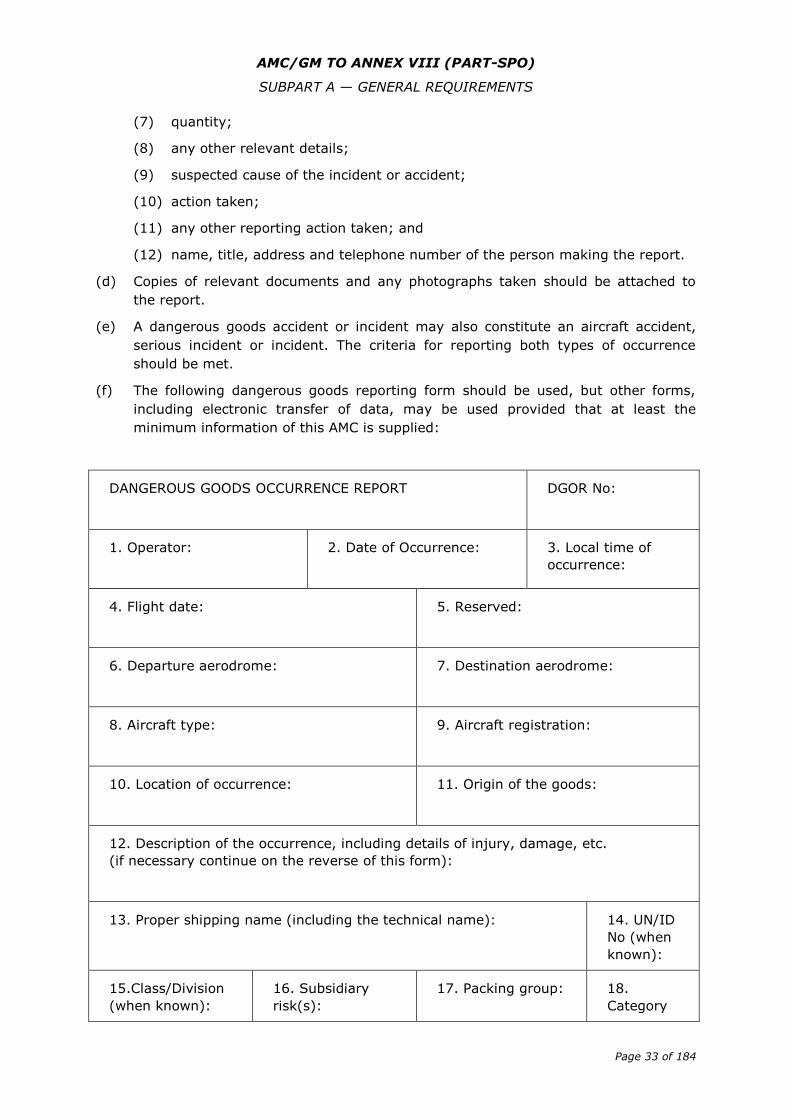
AMC/GM TO ANNEX VIII (PART-SPO)
SUBPART A — GENERAL REQUIREMENTS
Page 33 of 184
(7) quantity;
(8) any other relevant details;
(9) suspected cause of the incident or accident;
(10) action taken;
(11) any other reporting action taken; and
(12) name, title, address and telephone number of the person making the report.
(d) Copies of relevant documents and any photographs taken should be attached to
the report.
(e) A dangerous goods accident or incident may also constitute an aircraft accident,
serious incident or incident. The criteria for reporting both types of occurrence
should be met.
(f) The following dangerous goods reporting form should be used, but other forms,
including electronic transfer of data, may be used provided that at least the
minimum information of this AMC is supplied:
DANGEROUS GOODS OCCURRENCE REPORT
DGOR No:
1. Operator:
2. Date of Occurrence: 3. Local time of
occurrence:
4. Flight date:
5. Reserved:
6. Departure aerodrome:
7. Destination aerodrome:
8. Aircraft type:
9. Aircraft registration:
10. Location of occurrence:
11. Origin of the goods:
12. Description of the occurrence, including details of injury, damage, etc.
(if necessary continue on the reverse of this form):
13. Proper shipping name (including the technical name):
14. UN/ID
No (when
known):
15.Class/Division
(when known):
16. Subsidiary
risk(s):
17. Packing group: 18.
Category
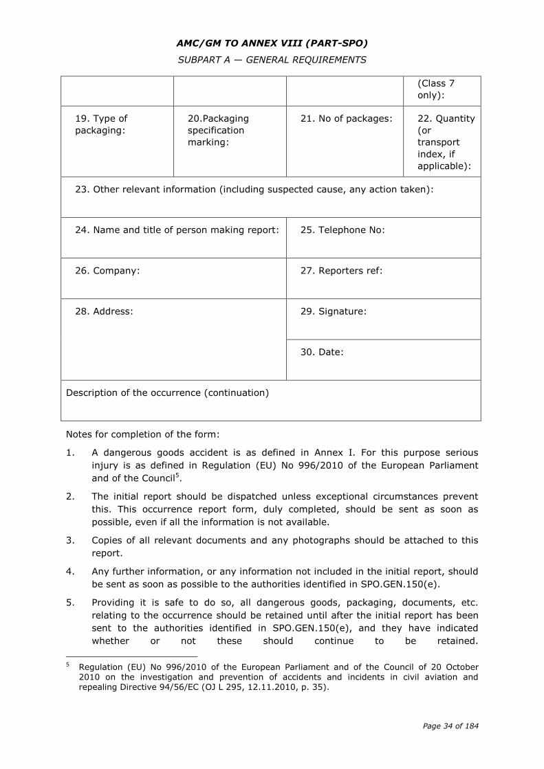
AMC/GM TO ANNEX VIII (PART-SPO)
SUBPART A — GENERAL REQUIREMENTS
Page 34 of 184
(Class 7
only):
19. Type of
packaging:
20.Packaging
specification
marking:
21. No of packages: 22. Quantity
(or
transport
index, if
applicable):
23. Other relevant information (including suspected cause, any action taken):
24. Name and title of person making report:
25. Telephone No:
26. Company:
27. Reporters ref:
28. Address: 29. Signature:
30. Date:
Description of the occurrence (continuation)
Notes for completion of the form:
1. A dangerous goods accident is as defined in Annex I. For this purpose serious
injury is as defined in Regulation (EU) No 996/2010 of the European Parliament
and of the Council5.
2. The initial report should be dispatched unless exceptional circumstances prevent
this. This occurrence report form, duly completed, should be sent as soon as
possible, even if all the information is not available.
3. Copies of all relevant documents and any photographs should be attached to this
report.
4. Any further information, or any information not included in the initial report, should
be sent as soon as possible to the authorities identified in SPO.GEN.150(e).
5. Providing it is safe to do so, all dangerous goods, packaging, documents, etc.
relating to the occurrence should be retained until after the initial report has been
sent to the authorities identified in SPO.GEN.150(e), and they have indicated
whether or not these should continue to be retained.
5 Regulation (EU) No 996/2010 of the European Parliament and of the Council of 20 October
2010 on the investigation and prevention of accidents and incidents in civil aviation and repealing Directive 94/56/EC (OJ L 295, 12.11.2010, p. 35).
AMC/GM TO ANNEX VIII (PART-SPO)
SUBPART B — OPERATIONAL PROCEDURES
Page 35 of 184
Subpart B — Operational procedures
AMC1 SPO.OP.100 Use of aerodromes and operating sites
USE OF OPERATING SITES MOTOR-POWERED AIRCRAFT
(a) When defining adequate operating sites for use for the type(s) of aircraft and
operation(s) concerned, the operator should take account of the following:
(1) An adequate site is a site that the operator considers to be satisfactory,
taking account of the applicable performance requirements and site
characteristics.
(2) The operator should have in place a procedure for the survey of operating
sites by a competent person. Such a procedure should take account for
possible changes to the operating site characteristics that may have taken
place since last surveyed.
(b) Operating sites that are pre-surveyed should be specifically specified in the
operations manual. The operations manual should contain diagrams or ground and
aerial photographs, depiction (pictorial) and description of:
(1) the overall dimensions of the operating site;
(2) location and height of relevant obstacles to approach and take-off profiles
and in the manoeuvring area;
(3) approach and take-off flight paths;
(4) surface condition (blowing dust/snow/sand);
(5) provision of control of third parties on the ground, if applicable;
(6) lighting, if applicable;
(7) procedure for activating the operating site in accordance with national
regulations, if applicable;
(8) other useful information, for example details of the appropriate ATS agency
and frequency; and
(9) site suitability with reference to available aircraft performance.
(c) Where the operator specifically permits operation from sites that are not pre-
surveyed, the pilot-in-command should make, from the air a judgement on the
suitability of a site. At least (b)(1) to (b)(6) inclusive and (b)(9) should be
considered. Operations to non-pre-surveyed operating sites by night should not be
conducted.
GM1 SPO.OP.100 Use of aerodromes and operating sites
ADEQUATE SITES — BALLOONS
An adequate site is a site that the pilot-in-command considers to be satisfactory, taking
account of the applicable performance requirements and site characteristics.
AMC/GM TO ANNEX VIII (PART-SPO)
SUBPART B — OPERATIONAL PROCEDURES
Page 36 of 184
AMC1 SPO.OP.110 Aerodrome operating minima — aeroplanes and helicopters
COMMERCIALLY AVAILABLE INFORMATION
An acceptable method of specifying aerodrome operating minima is through the use of
commercially available information.
AMC2 SPO.OP.110 Aerodrome operating minima – aeroplanes and helicopters
VISUAL APPROACH OPERATIONS
For a visual approach operation, the runway visual range (RVR) should not be less than
800 m.
AMC3 SPO.OP.110 Aerodrome operating minima — aeroplanes and helicopters
GENERAL
(a) The aerodrome operating minima should not be lower than as specified in
SPO.OP.111 or AMC4 SPO.OP.110(c).
(b) Whenever practical approaches should be flown as stabilised approaches (SAps).
Different procedures may be used for a particular approach to a particular runway.
(c) Whenever practical, non-precision approaches should be flown using the
continuous descent final approach (CDFA) technique. Different procedures may be
used for a particular approach to a particular runway.
(d) For approaches not flown using the CDFA technique: when calculating the minima
in accordance with SPO.OP.111, the applicable minimum runway visual range
(RVR) should be increased by 200 m for Category A and B aeroplanes and by
400 m for Category C and D aeroplanes, provided the resulting RVR/converted
meteorological visibility (CMV) value does not exceed 5 000 m. SAp or CDFA should
be used as soon as facilities are improved to allow these techniques.
AMC4 SPO.OP.110 Aerodrome operating minima — aeroplanes and helicopters
TAKE-OFF OPERATIONS WITH COMPLEX MOTOR-POWERED AIRCRAFT
(a) General:
(1) Take-off minima should be expressed as visibility (VIS) or RVR limits, taking
into account all relevant factors for each aerodrome planned to be used and
aircraft characteristics. Where there is a specific need to see and avoid
obstacles on departure and/or for a forced landing, additional conditions, e.g.
ceiling, should be specified.
(2) The pilot-in-command should not commence take-off unless the weather
conditions at the aerodrome of departure are equal to or better than
applicable minima for landing at that aerodrome, unless a weather-
permissible take-off alternate aerodrome is available.
(3) When the reported meteorological visibility is below that required for take-off
and RVR is not reported, a take-off should only be commenced if the pilot-in-
command can determine that the visibility along the take-off runway/area is
equal to or better than the required minimum.
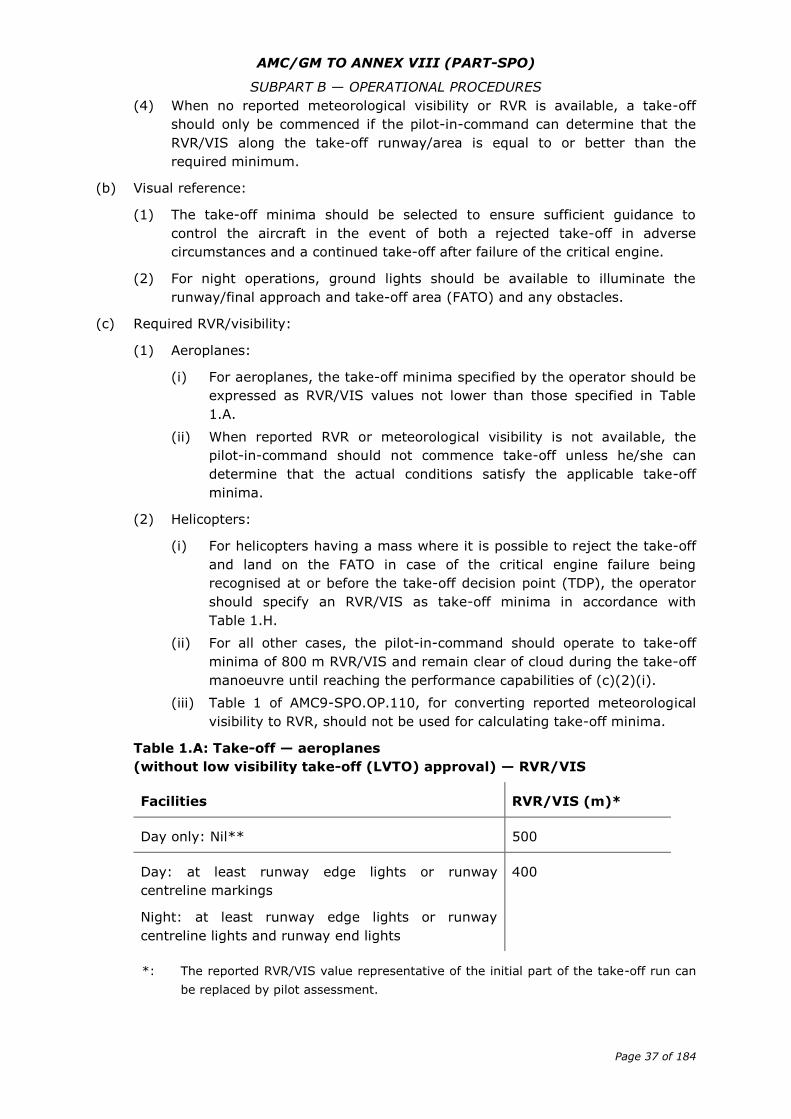
AMC/GM TO ANNEX VIII (PART-SPO)
SUBPART B — OPERATIONAL PROCEDURES
Page 37 of 184
(4) When no reported meteorological visibility or RVR is available, a take-off
should only be commenced if the pilot-in-command can determine that the
RVR/VIS along the take-off runway/area is equal to or better than the
required minimum.
(b) Visual reference:
(1) The take-off minima should be selected to ensure sufficient guidance to
control the aircraft in the event of both a rejected take-off in adverse
circumstances and a continued take-off after failure of the critical engine.
(2) For night operations, ground lights should be available to illuminate the
runway/final approach and take-off area (FATO) and any obstacles.
(c) Required RVR/visibility:
(1) Aeroplanes:
(i) For aeroplanes, the take-off minima specified by the operator should be
expressed as RVR/VIS values not lower than those specified in Table
1.A.
(ii) When reported RVR or meteorological visibility is not available, the
pilot-in-command should not commence take-off unless he/she can
determine that the actual conditions satisfy the applicable take-off
minima.
(2) Helicopters:
(i) For helicopters having a mass where it is possible to reject the take-off
and land on the FATO in case of the critical engine failure being
recognised at or before the take-off decision point (TDP), the operator
should specify an RVR/VIS as take-off minima in accordance with
Table 1.H.
(ii) For all other cases, the pilot-in-command should operate to take-off
minima of 800 m RVR/VIS and remain clear of cloud during the take-off
manoeuvre until reaching the performance capabilities of (c)(2)(i).
(iii) Table 1 of AMC9-SPO.OP.110, for converting reported meteorological
visibility to RVR, should not be used for calculating take-off minima.
Table 1.A: Take-off — aeroplanes
(without low visibility take-off (LVTO) approval) — RVR/VIS
Facilities RVR/VIS (m)*
Day only: Nil** 500
Day: at least runway edge lights or runway
centreline markings
Night: at least runway edge lights or runway
centreline lights and runway end lights
400
*: The reported RVR/VIS value representative of the initial part of the take-off run can
be replaced by pilot assessment.
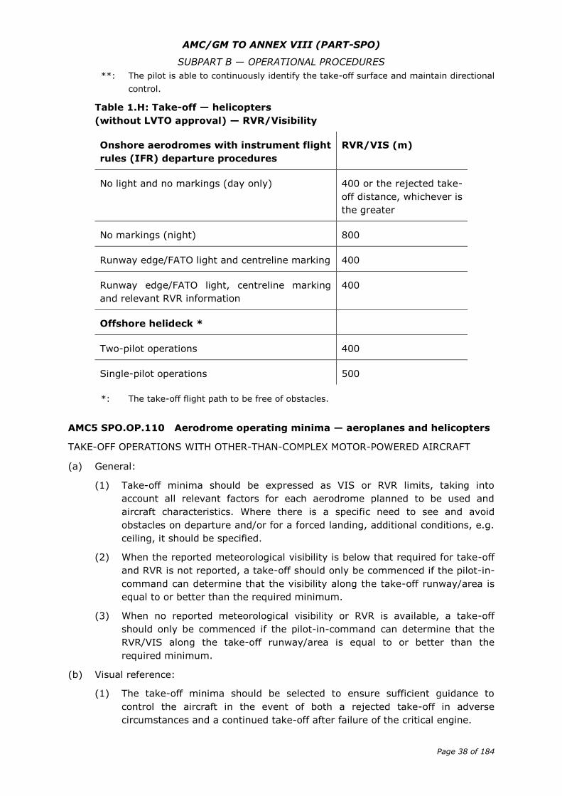
AMC/GM TO ANNEX VIII (PART-SPO)
SUBPART B — OPERATIONAL PROCEDURES
Page 38 of 184
**: The pilot is able to continuously identify the take-off surface and maintain directional
control.
Table 1.H: Take-off — helicopters
(without LVTO approval) — RVR/Visibility
Onshore aerodromes with instrument flight
rules (IFR) departure procedures
RVR/VIS (m)
No light and no markings (day only) 400 or the rejected take-
off distance, whichever is
the greater
No markings (night) 800
Runway edge/FATO light and centreline marking 400
Runway edge/FATO light, centreline marking
and relevant RVR information
400
Offshore helideck *
Two-pilot operations 400
Single-pilot operations 500
*: The take-off flight path to be free of obstacles.
AMC5 SPO.OP.110 Aerodrome operating minima — aeroplanes and helicopters
TAKE-OFF OPERATIONS WITH OTHER-THAN-COMPLEX MOTOR-POWERED AIRCRAFT
(a) General:
(1) Take-off minima should be expressed as VIS or RVR limits, taking into
account all relevant factors for each aerodrome planned to be used and
aircraft characteristics. Where there is a specific need to see and avoid
obstacles on departure and/or for a forced landing, additional conditions, e.g.
ceiling, it should be specified.
(2) When the reported meteorological visibility is below that required for take-off
and RVR is not reported, a take-off should only be commenced if the pilot-in-
command can determine that the visibility along the take-off runway/area is
equal to or better than the required minimum.
(3) When no reported meteorological visibility or RVR is available, a take-off
should only be commenced if the pilot-in-command can determine that the
RVR/VIS along the take-off runway/area is equal to or better than the
required minimum.
(b) Visual reference:
(1) The take-off minima should be selected to ensure sufficient guidance to
control the aircraft in the event of both a rejected take-off in adverse
circumstances and a continued take-off after failure of the critical engine.
AMC/GM TO ANNEX VIII (PART-SPO)
SUBPART B — OPERATIONAL PROCEDURES
Page 39 of 184
(2) For night operations, ground lights should be available to illuminate the
runway/final approach and take-off area (FATO) and any obstacles.
AMC6 SPO.OP.110 Aerodrome operating minima — aeroplanes and helicopters
CRITERIA FOR ESTABLISHING RVR/CMV
(a) In order to qualify for the lowest allowable values of RVR/CMV specified in
Table 4.A of AMC7 SPO.OP.110, the instrument approach should meet at least the
following facility requirements and associated conditions:
(1) Instrument approaches with designated vertical profile up to and including
4.5° for Category A and B aeroplanes, or 3.77° for Category C and D
aeroplanes, where the facilities are:
(i) instrument landing system (ILS)/microwave landing system
(MLS)/GBAS landing system (GLS)/precision approach radar (PAR)); or
(ii) approach procedure with vertical guidance (APV); and
where the final approach track is offset by not more than 15° for Category A
and B aeroplanes or by not more than 5° for Category C and D aeroplanes.
(2) Instrument approach operations flown using the CDFA technique with a
nominal vertical profile, up to and including 4.5° for Category A and B
aeroplanes, or 3.77° for Category C and D aeroplanes, where the facilities are
non-directional beacon (NDB), NDB/distance measuring equipment (DME),
VHF omnidirectional radio range (VOR), VOR/DME, localiser (LOC), LOC/DME,
VHF direction finder (VDF), surveillance radar approach (SRA) or global
navigation satellite system (GNSS)/lateral navigation (LNAV), with a final
approach segment of at least 3 NM, which also fulfil the following criteria:
(i) the final approach track is offset by not more than 15° for Category A
and B aeroplanes or by not more than 5° for Category C and D
aeroplanes;
(ii) the final approach fix (FAF) or another appropriate fix where descent is
initiated is available, or distance to threshold (THR) is available by flight
management system (FMS)/area navigation (NDB/DME) or DME; and
(iii) the missed approach point (MAPt) is determined by timing, the distance
from FAF to THR is ≤ 8 NM.
(3) Instrument approaches where the facilities are NDB, NDB/DME, VOR,
VOR/DME, LOC, LOC/DME, VDF, SRA or GNSS/LNAV, not fulfilling the criteria
in (a)(2), or with an minimum descent height (MDH) ≥ 1 200 ft.
(b) The missed approach operation, after an approach operation has been flown using
the CDFA technique, should be executed when reaching the decision height/altitude
(DH/A) or the MAPt, whichever occurs first. The lateral part of the missed approach
procedure should be flown via the MAPt unless otherwise stated on the approach
chart.
AMC/GM TO ANNEX VIII (PART-SPO)
SUBPART B — OPERATIONAL PROCEDURES
Page 40 of 184
AMC7 SPO.OP.110 Aerodrome operating minima — aeroplanes and helicopters
DETERMINATION OF RVR/CMV/VIS MINIMA FOR NPA, APV, CAT I — AEROPLANES
(a) The minimum RVR/CMV/VIS should be the highest of the values specified in
Table 3 and Table 4.A but not greater than the maximum values specified in
Table 4.A, where applicable.
(b) The values in Table 2 should be derived from the formula below:
required RVR/VIS (m) = [(DH/MDH (ft) x 0.3048) / tanα] — length of
approach lights (m);
where α is the calculation angle, being a default value of 3.00° increasing in
steps of 0.10° for each line in Table 3 up to 3.77° and then remaining
constant.
(c) If the approach is flown with a level flight segment at or above MDA/H, 200 m
should be added for Category A and B aeroplanes and 400 m for Category C and D
aeroplanes to the minimum RVR/CMV/VIS value resulting from the application of
Table 3 and Table 4.A.
(d) An RVR of less than 750 m as indicated in Table 3 may be used:
(1) for CAT I operations to runways with full approach lighting system (FALS),
runway touchdown zone lights (RTZL) and runway centreline lights (RCLL);
(2) for CAT I operations to runways without RTZL and RCLL when using an
approved head-up guidance landing system (HUDLS), or equivalent approved
system, or when conducting a coupled approach or flight-director-flown
approach to a DH. The ILS should not be published as a restricted facility;
and
(3) for APV operations to runways with FALS, RTZL and RCLL when using an
approved head-up display (HUD).
(e) Lower values than those specified in Table 3 may be used for HUDLS and auto-land
operations if approved in accordance with Annex V (Part-SPA), Subpart E.
(f) The visual aids should comprise standard runway day markings and approach and
runway lights as specified in Table 2.
(g) For night operations or for any operation where credit for runway and approach
lights is required, the lights should be on and serviceable, except as provided for in
Table 6 of AMC 10 SPO.OP.110.
(h) For single-pilot operations, the minimum RVR/VIS should be calculated in
accordance with the following additional criteria:
(1) an RVR of less than 800 m as indicated in Table 3 may be used for CAT I
approaches provided any of the following is used at least down to the
applicable DH:
(i) a suitable autopilot, coupled to an ILS, MLS or GLS that is not published
as restricted; or
(ii) an approved HUDLS, including, where appropriate, enhanced vision
system (EVS), or equivalent approved system;
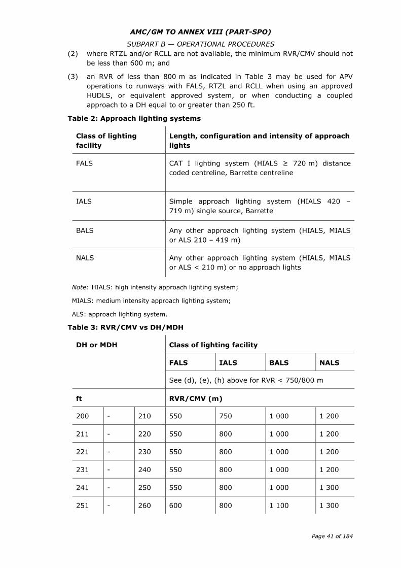
AMC/GM TO ANNEX VIII (PART-SPO)
SUBPART B — OPERATIONAL PROCEDURES
Page 41 of 184
(2) where RTZL and/or RCLL are not available, the minimum RVR/CMV should not
be less than 600 m; and
(3) an RVR of less than 800 m as indicated in Table 3 may be used for APV
operations to runways with FALS, RTZL and RCLL when using an approved
HUDLS, or equivalent approved system, or when conducting a coupled
approach to a DH equal to or greater than 250 ft.
Table 2: Approach lighting systems
Class of lighting
facility
Length, configuration and intensity of approach
lights
FALS CAT I lighting system (HIALS ≥ 720 m) distance
coded centreline, Barrette centreline
IALS Simple approach lighting system (HIALS 420 –
719 m) single source, Barrette
BALS Any other approach lighting system (HIALS, MIALS
or ALS 210 – 419 m)
NALS Any other approach lighting system (HIALS, MIALS
or ALS < 210 m) or no approach lights
Note: HIALS: high intensity approach lighting system;
MIALS: medium intensity approach lighting system;
ALS: approach lighting system.
Table 3: RVR/CMV vs DH/MDH
DH or MDH Class of lighting facility
FALS IALS BALS NALS
See (d), (e), (h) above for RVR < 750/800 m
ft RVR/CMV (m)
200 - 210 550 750 1 000 1 200
211 - 220 550 800 1 000 1 200
221 - 230 550 800 1 000 1 200
231 - 240 550 800 1 000 1 200
241 - 250 550 800 1 000 1 300
251 - 260 600 800 1 100 1 300
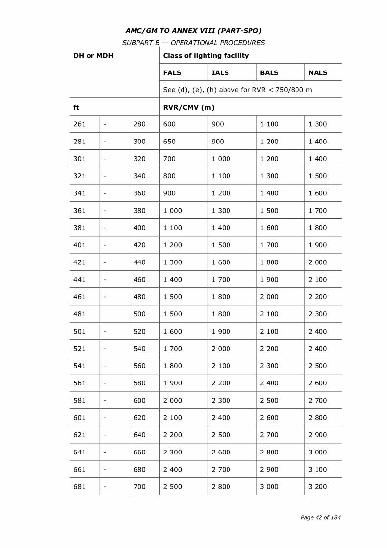
AMC/GM TO ANNEX VIII (PART-SPO)
SUBPART B — OPERATIONAL PROCEDURES
Page 42 of 184
DH or MDH Class of lighting facility
FALS IALS BALS NALS
See (d), (e), (h) above for RVR < 750/800 m
ft RVR/CMV (m)
261 - 280 600 900 1 100 1 300
281 - 300 650 900 1 200 1 400
301 - 320 700 1 000 1 200 1 400
321 - 340 800 1 100 1 300 1 500
341 - 360 900 1 200 1 400 1 600
361 - 380 1 000 1 300 1 500 1 700
381 - 400 1 100 1 400 1 600 1 800
401 - 420 1 200 1 500 1 700 1 900
421 - 440 1 300 1 600 1 800 2 000
441 - 460 1 400 1 700 1 900 2 100
461 - 480 1 500 1 800 2 000 2 200
481 500 1 500 1 800 2 100 2 300
501 - 520 1 600 1 900 2 100 2 400
521 - 540 1 700 2 000 2 200 2 400
541 - 560 1 800 2 100 2 300 2 500
561 - 580 1 900 2 200 2 400 2 600
581 - 600 2 000 2 300 2 500 2 700
601 - 620 2 100 2 400 2 600 2 800
621 - 640 2 200 2 500 2 700 2 900
641 - 660 2 300 2 600 2 800 3 000
661 - 680 2 400 2 700 2 900 3 100
681 - 700 2 500 2 800 3 000 3 200
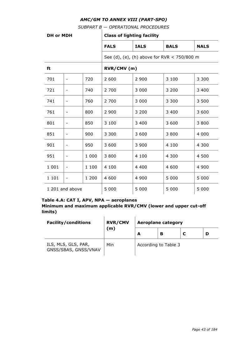
AMC/GM TO ANNEX VIII (PART-SPO)
SUBPART B — OPERATIONAL PROCEDURES
Page 43 of 184
DH or MDH Class of lighting facility
FALS IALS BALS NALS
See (d), (e), (h) above for RVR < 750/800 m
ft RVR/CMV (m)
701 - 720 2 600 2 900 3 100 3 300
721 - 740 2 700 3 000 3 200 3 400
741 - 760 2 700 3 000 3 300 3 500
761 - 800 2 900 3 200 3 400 3 600
801 - 850 3 100 3 400 3 600 3 800
851 - 900 3 300 3 600 3 800 4 000
901 - 950 3 600 3 900 4 100 4 300
951 - 1 000 3 800 4 100 4 300 4 500
1 001 - 1 100 4 100 4 400 4 600 4 900
1 101 - 1 200 4 600 4 900 5 000 5 000
1 201 and above 5 000 5 000 5 000 5 000
Table 4.A: CAT I, APV, NPA — aeroplanes
Minimum and maximum applicable RVR/CMV (lower and upper cut-off
limits)
Facility/conditions RVR/CMV
(m)
Aeroplane category
A B C D
ILS, MLS, GLS, PAR,
GNSS/SBAS, GNSS/VNAV Min According to Table 3
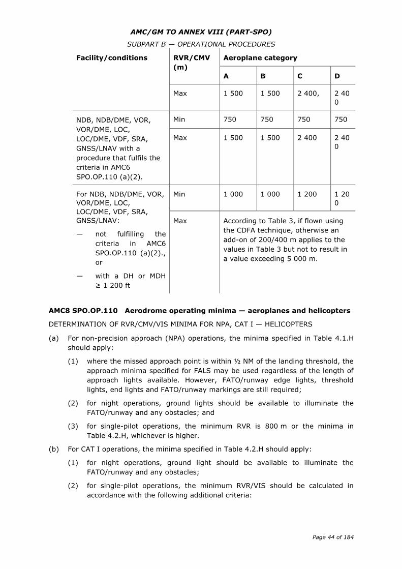
AMC/GM TO ANNEX VIII (PART-SPO)
SUBPART B — OPERATIONAL PROCEDURES
Page 44 of 184
Facility/conditions RVR/CMV
(m)
Aeroplane category
A B C D
Max 1 500 1 500 2 400, 2 40
0
NDB, NDB/DME, VOR,
VOR/DME, LOC,
LOC/DME, VDF, SRA,
GNSS/LNAV with a
procedure that fulfils the
criteria in AMC6
SPO.OP.110 (a)(2).
Min 750 750 750 750
Max 1 500 1 500 2 400 2 40
0
For NDB, NDB/DME, VOR,
VOR/DME, LOC,
LOC/DME, VDF, SRA,
GNSS/LNAV:
— not fulfilling the
criteria in AMC6
SPO.OP.110 (a)(2).,
or
— with a DH or MDH
≥ 1 200 ft
Min 1 000 1 000 1 200 1 20
0
Max According to Table 3, if flown using
the CDFA technique, otherwise an
add-on of 200/400 m applies to the
values in Table 3 but not to result in
a value exceeding 5 000 m.
AMC8 SPO.OP.110 Aerodrome operating minima — aeroplanes and helicopters
DETERMINATION OF RVR/CMV/VIS MINIMA FOR NPA, CAT I — HELICOPTERS
(a) For non-precision approach (NPA) operations, the minima specified in Table 4.1.H
should apply:
(1) where the missed approach point is within ½ NM of the landing threshold, the
approach minima specified for FALS may be used regardless of the length of
approach lights available. However, FATO/runway edge lights, threshold
lights, end lights and FATO/runway markings are still required;
(2) for night operations, ground lights should be available to illuminate the
FATO/runway and any obstacles; and
(3) for single-pilot operations, the minimum RVR is 800 m or the minima in
Table 4.2.H, whichever is higher.
(b) For CAT I operations, the minima specified in Table 4.2.H should apply:
(1) for night operations, ground light should be available to illuminate the
FATO/runway and any obstacles;
(2) for single-pilot operations, the minimum RVR/VIS should be calculated in
accordance with the following additional criteria:
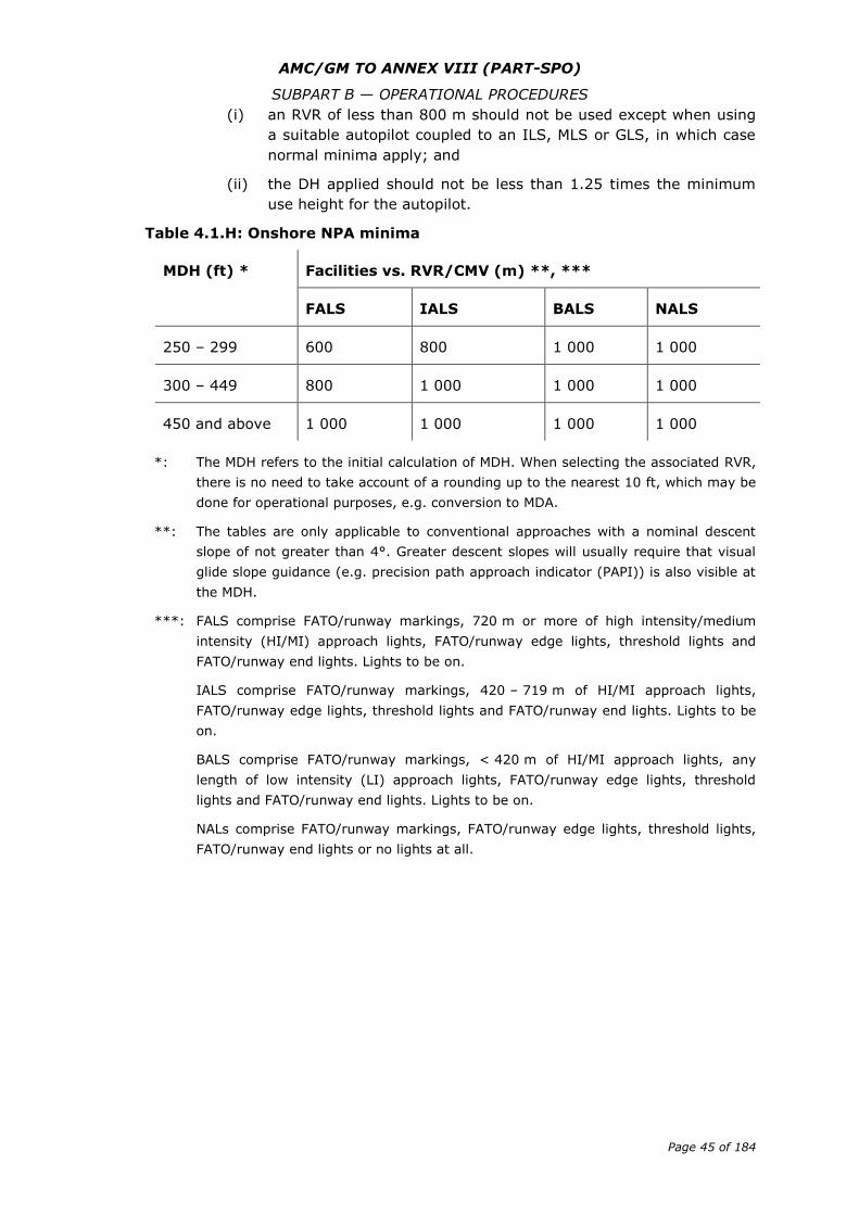
AMC/GM TO ANNEX VIII (PART-SPO)
SUBPART B — OPERATIONAL PROCEDURES
Page 45 of 184
(i) an RVR of less than 800 m should not be used except when using
a suitable autopilot coupled to an ILS, MLS or GLS, in which case
normal minima apply; and
(ii) the DH applied should not be less than 1.25 times the minimum
use height for the autopilot.
Table 4.1.H: Onshore NPA minima
MDH (ft) *
Facilities vs. RVR/CMV (m) **, ***
FALS IALS BALS NALS
250 – 299 600 800 1 000 1 000
300 – 449 800 1 000 1 000 1 000
450 and above 1 000 1 000 1 000 1 000
*: The MDH refers to the initial calculation of MDH. When selecting the associated RVR,
there is no need to take account of a rounding up to the nearest 10 ft, which may be
done for operational purposes, e.g. conversion to MDA.
**: The tables are only applicable to conventional approaches with a nominal descent
slope of not greater than 4°. Greater descent slopes will usually require that visual
glide slope guidance (e.g. precision path approach indicator (PAPI)) is also visible at
the MDH.
***: FALS comprise FATO/runway markings, 720 m or more of high intensity/medium
intensity (HI/MI) approach lights, FATO/runway edge lights, threshold lights and
FATO/runway end lights. Lights to be on.
IALS comprise FATO/runway markings, 420 – 719 m of HI/MI approach lights,
FATO/runway edge lights, threshold lights and FATO/runway end lights. Lights to be
on.
BALS comprise FATO/runway markings, < 420 m of HI/MI approach lights, any
length of low intensity (LI) approach lights, FATO/runway edge lights, threshold
lights and FATO/runway end lights. Lights to be on.
NALs comprise FATO/runway markings, FATO/runway edge lights, threshold lights,
FATO/runway end lights or no lights at all.
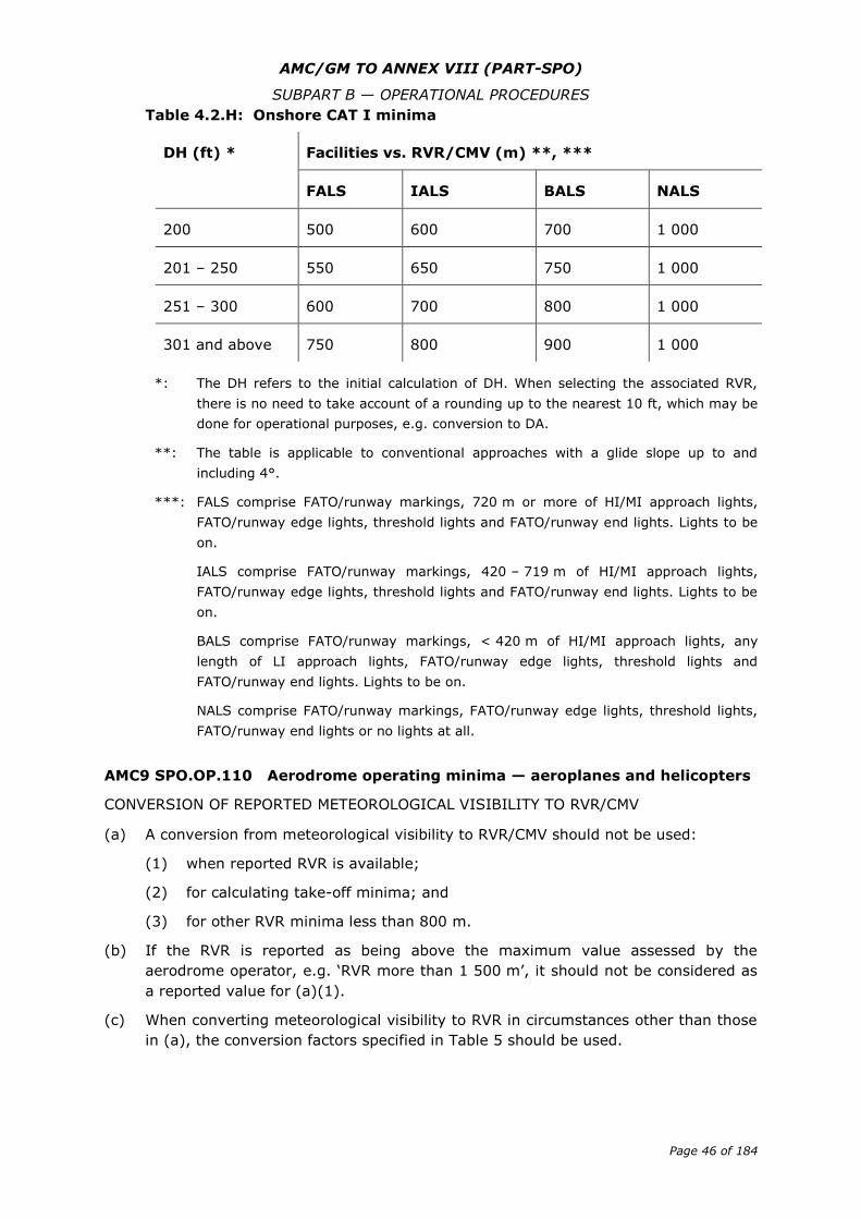
AMC/GM TO ANNEX VIII (PART-SPO)
SUBPART B — OPERATIONAL PROCEDURES
Page 46 of 184
Table 4.2.H: Onshore CAT I minima
DH (ft) * Facilities vs. RVR/CMV (m) **, ***
FALS IALS BALS NALS
200 500 600 700 1 000
201 – 250 550 650 750 1 000
251 – 300 600 700 800 1 000
301 and above 750 800 900 1 000
*: The DH refers to the initial calculation of DH. When selecting the associated RVR,
there is no need to take account of a rounding up to the nearest 10 ft, which may be
done for operational purposes, e.g. conversion to DA.
**: The table is applicable to conventional approaches with a glide slope up to and
including 4°.
***: FALS comprise FATO/runway markings, 720 m or more of HI/MI approach lights,
FATO/runway edge lights, threshold lights and FATO/runway end lights. Lights to be
on.
IALS comprise FATO/runway markings, 420 – 719 m of HI/MI approach lights,
FATO/runway edge lights, threshold lights and FATO/runway end lights. Lights to be
on.
BALS comprise FATO/runway markings, < 420 m of HI/MI approach lights, any
length of LI approach lights, FATO/runway edge lights, threshold lights and
FATO/runway end lights. Lights to be on.
NALS comprise FATO/runway markings, FATO/runway edge lights, threshold lights,
FATO/runway end lights or no lights at all.
AMC9 SPO.OP.110 Aerodrome operating minima — aeroplanes and helicopters
CONVERSION OF REPORTED METEOROLOGICAL VISIBILITY TO RVR/CMV
(a) A conversion from meteorological visibility to RVR/CMV should not be used:
(1) when reported RVR is available;
(2) for calculating take-off minima; and
(3) for other RVR minima less than 800 m.
(b) If the RVR is reported as being above the maximum value assessed by the
aerodrome operator, e.g. ‘RVR more than 1 500 m’, it should not be considered as
a reported value for (a)(1).
(c) When converting meteorological visibility to RVR in circumstances other than those
in (a), the conversion factors specified in Table 5 should be used.
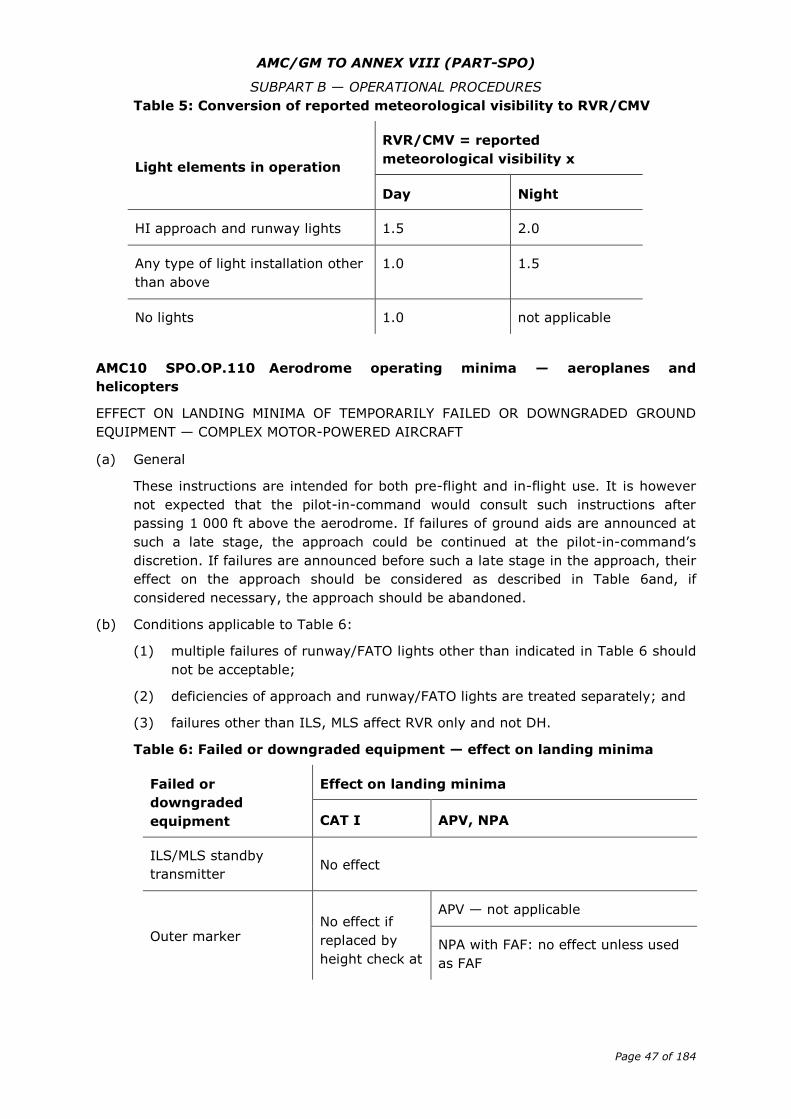
AMC/GM TO ANNEX VIII (PART-SPO)
SUBPART B — OPERATIONAL PROCEDURES
Page 47 of 184
Table 5: Conversion of reported meteorological visibility to RVR/CMV
Light elements in operation
RVR/CMV = reported
meteorological visibility x
Day Night
HI approach and runway lights 1.5 2.0
Any type of light installation other
than above
1.0 1.5
No lights 1.0 not applicable
AMC10 SPO.OP.110 Aerodrome operating minima — aeroplanes and
helicopters
EFFECT ON LANDING MINIMA OF TEMPORARILY FAILED OR DOWNGRADED GROUND
EQUIPMENT — COMPLEX MOTOR-POWERED AIRCRAFT
(a) General
These instructions are intended for both pre-flight and in-flight use. It is however
not expected that the pilot-in-command would consult such instructions after
passing 1 000 ft above the aerodrome. If failures of ground aids are announced at
such a late stage, the approach could be continued at the pilot-in-command’s
discretion. If failures are announced before such a late stage in the approach, their
effect on the approach should be considered as described in Table 6and, if
considered necessary, the approach should be abandoned.
(b) Conditions applicable to Table 6:
(1) multiple failures of runway/FATO lights other than indicated in Table 6 should
not be acceptable;
(2) deficiencies of approach and runway/FATO lights are treated separately; and
(3) failures other than ILS, MLS affect RVR only and not DH.
Table 6: Failed or downgraded equipment — effect on landing minima
Failed or
downgraded
equipment
Effect on landing minima
CAT I APV, NPA
ILS/MLS standby
transmitter No effect
Outer marker No effect if
replaced by
height check at
APV — not applicable
NPA with FAF: no effect unless used
as FAF
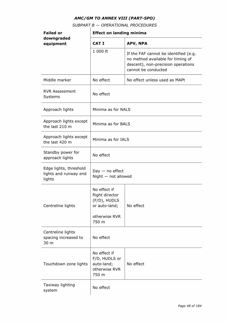
AMC/GM TO ANNEX VIII (PART-SPO)
SUBPART B — OPERATIONAL PROCEDURES
Page 48 of 184
Failed or
downgraded
equipment
Effect on landing minima
CAT I APV, NPA
1 000 ft If the FAF cannot be identified (e.g.
no method available for timing of
descent), non-precision operations
cannot be conducted
Middle marker No effect No effect unless used as MAPt
RVR Assessment
Systems No effect
Approach lights Minima as for NALS
Approach lights except
the last 210 m Minima as for BALS
Approach lights except
the last 420 m Minima as for IALS
Standby power for
approach lights No effect
Edge lights, threshold
lights and runway end
lights
Day — no effect
Night — not allowed
Centreline lights
No effect if
flight director
(F/D), HUDLS
or auto-land;
otherwise RVR
750 m
No effect
Centreline lights
spacing increased to
30 m
No effect
Touchdown zone lights
No effect if
F/D, HUDLS or
auto-land;
otherwise RVR
750 m
No effect
Taxiway lighting
system No effect
AMC/GM TO ANNEX VIII (PART-SPO)
SUBPART B — OPERATIONAL PROCEDURES
Page 49 of 184
AMC11 SPO.OP.110 Aerodrome operating minima — aeroplanes and
helicopters
EFFECT ON LANDING MINIMA OF TEMPORARILY FAILED OR DOWNGRADED GROUND
EQUIPMENT — OTHER-THAN-COMPLEX MOTOR-POWERED AIRCRAFT
(a) Non-precision approaches requiring a final approach fix (FAF) and/or MAPt should
not be conducted where a method of identifying the appropriate fix is not available.
(b) A minimum RVR of 750 m should be used for CAT I operations in the absence of
centreline lines and/or touchdown zone lights.
(c) Where approach lighting is partly unavailable, minima should take account of the
serviceable length of approach lighting.
GM1 SPO.OP.110 Aerodrome operating minima — aeroplanes and helicopters
AIRCRAFT CATEGORIES
(a) Aircraft categories should be based on the indicated airspeed at threshold (VAT),
which is equal to the stalling speed (VSO) multiplied by 1.3 or where published 1-g
(gravity) stall speed (VS1g) multiplied by 1.23 in the landing configuration at the
maximum certified landing mass. If both VSO and VS1g are available, the higher
resulting VAT should be used.
(b) The aircraft categories specified in Table 1 should be used.
Table 1: Aircraft categories corresponding to VAT values
Aircraft
category
VAT
A Less than 91 kt
B from 91 to 120 kt
C from 121 to 140 kt
D from 141 to 165 kt
E from 166 to 210 kt
GM2 SPO.OP.110 Aerodrome operating minima — aeroplanes and helicopters
CONTINUOUS DESCENT FINAL APPROACH (CDFA) — AEROPLANES
(a) Introduction
(1) Controlled flight into terrain (CFIT) is a major hazard in aviation. Most CFIT
accidents occur in the final approach segment of non-precision approaches;
the use of stabilised-approach criteria on a continuous descent with a
constant, predetermined vertical path is seen as a major improvement in
safety during the conduct of such approaches. Operators should ensure that
the following techniques are adopted as widely as possible, for all
approaches.
AMC/GM TO ANNEX VIII (PART-SPO)
SUBPART B — OPERATIONAL PROCEDURES
Page 50 of 184
(2) The elimination of level flight segments at MDA close to the ground during
approaches, and the avoidance of major changes in attitude and power/thrust
close to the runway that can destabilise approaches, are seen as ways to
reduce operational risks significantly.
(3) The term CDFA has been selected to cover a flight technique for any type of
NPA operation.
(4) The advantages of CDFA are as follows:
(i) the technique enhances safe approach operations by the utilisation of
standard operating practices;
(ii) the technique is similar to that used when flying an ILS approach,
including when executing the missed approach and the associated
missed approach procedure manoeuvre;
(iii) the aeroplane attitude may enable better acquisition of visual cues;
(iv) the technique may reduce pilot workload;
(v) the approach profile is fuel efficient;
(vi) the approach profile affords reduced noise levels; and
(vii) the technique affords procedural integration with APV operations.
(b) CDFA
(1) Continuous descent final approach is defined in Annex I to the Regulation on
Air operations.
(2) An approach is only suitable for application of a CDFA technique when it is
flown along a nominal vertical profile; a nominal vertical profile is not forming
part of the approach procedure design, but can be flown as a continuous
descent. The nominal vertical profile information may be published or
displayed on the approach chart to the pilot by depicting the nominal slope or
range/distance vs height. Approaches with a nominal vertical profile are
considered to be:
(i) NDB, NDB/DME;
(ii) VOR, VOR/DME;
(iii) LOC, LOC/DME;
(iv) VDF, SRA; and
(v) GNSS/LNAV.
(3) Stabilised approach (SAp) is defined in Annex I to the Regulation on Air
Operations.
(i) The control of the descent path is not the only consideration when using
the CDFA technique. Control of the aeroplane’s configuration and
energy is also vital to the safe conduct of an approach.
(ii) The control of the flight path, described above as one of the
requirements for conducting an SAp, should not be confused with the
path requirements for using the CDFA technique.
(iii) The predetermined approach slope requirements for applying the CDFA
technique are established by the following:
AMC/GM TO ANNEX VIII (PART-SPO)
SUBPART B — OPERATIONAL PROCEDURES
Page 51 of 184
(A) the published ‘nominal’ slope information when the approach has
a nominal vertical profile; and
(B) the designated final-approach segment minimum of 3 NM, and
maximum, when using timing techniques, of 8 NM.
(iv) An SAp will never have any level segment of flight at DA/H or MDA/H,
as applicable. This enhances safety by mandating a prompt missed
approach procedure manoeuvre at DA/H or MDA/H.
(v) An approach using the CDFA technique will always be flown as an SAp,
since this is a requirement for applying CDFA. However, an SAp does
not have to be flown using the CDFA technique, for example a visual
approach.
GM3 SPO.OP.110 Aerodrome operating minima — aeroplanes and helicopters
ONSHORE AERODROME DEPARTURE PROCEDURES — OPERATIONS WITH NON-COMPLEX
HELICOPTERS
The cloud base and visibility should be such as to allow the helicopter to be clear of cloud
at the take-off decision point (TDP), and for the pilot flying to remain in sight of the
surface until reaching the minimum speed for flight in instrument meteorological
conditions, as given in the AFM.
GM4 SPO.OP.110 Aerodrome operating minima — aeroplanes and helicopters
TAKE-OFF MINIMA — OPERATIONS WITH COMPLEX HELICOPTERS
(a) To ensure sufficient control of the helicopter in IMC, the speed, before entering in
IMC, should be above the minimum authorised speed in IMC, Vmini. This is a
limitation in the AFM. Therefore, the lowest speed before entering in IMC is the
highest of Vtoss (velocity take-off safety speed) and Vmini.
(b) As example, Vtoss is 45 kt and Vmini 60 kt. In that case, the take–off minima have to
include the distance to accelerate to 60 kt. The take-off distance should be
increased accordingly.
GM1 SPO.OP.112 Aerodrome operating minima — circling operations with
aeroplanes
SUPPLEMENTAL INFORMATION
(a) The purpose of this Guidance Material is to provide operators with supplemental
information regarding the application of aerodrome operating minima in relation to
circling approaches.
(b) Conduct of flight — general:
(1) the MDH and obstacle clearance height (OCH) included in the procedure are
referenced to aerodrome elevation;
(2) the MDA is referenced to mean sea level;
(3) for these procedures, the applicable visibility is the meteorological visibility;
and
AMC/GM TO ANNEX VIII (PART-SPO)
SUBPART B — OPERATIONAL PROCEDURES
Page 52 of 184
(4) operators should provide tabular guidance of the relationship between height
above threshold and the in-flight visibility required to obtain and sustain
visual contact during the circling manoeuvre.
(c) Instrument approach followed by visual manoeuvring (circling) without prescribed
tracks:
(1) When the aeroplane is on the initial instrument approach, before visual
reference is stabilised, but not below MDA/H, the aeroplane should follow the
corresponding instrument approach procedure until the appropriate
instrument MAPt is reached.
(2) At the beginning of the level flight phase at or above the MDA/H, the
instrument approach track determined by the radio navigation aids, RNAV,
RNP, ILS, MLS or GLS should be maintained until the pilot:
(i) estimates that, in all probability, visual contact with the runway of
intended landing or the runway environment will be maintained during
the entire circling procedure;
(ii) estimates that the aeroplane is within the circling area before
commencing circling; and
(iii) is able to determine the aeroplane’s position in relation to the runway of
intended landing with the aid of the appropriate external references.
(3) When reaching the published instrument MAPt and the conditions stipulated
in (c)(2) are unable to be established by the pilot, a missed approach should
be carried out in accordance with that instrument approach procedure.
(4) After the aeroplane has left the track of the initial instrument approach, the
flight phase outbound from the runway should be limited to an appropriate
distance, which is required to align the aeroplane onto the final approach.
Such manoeuvres should be conducted to enable the aeroplane:
(i) to attain a controlled and stable descent path to the intended landing
runway; and
(ii) to remain within the circling area and in such way that visual contact
with the runway of intended landing or runway environment is
maintained at all times.
(5) Flight manoeuvres should be carried out at an altitude/height that is not less
than the circling MDA/H.
(6) Descent below MDA/H should not be initiated until the threshold of the
runway to be used has been appropriately identified. The aeroplane should be
in a position to continue with a normal rate of descent and land within the
touchdown zone.
(d) Instrument approach followed by a visual manoeuvring (circling) with prescribed
track.
(1) The aeroplane should remain on the initial instrument approach procedure
until one of the following is reached:
(i) the prescribed divergence point to commence circling on the prescribed
track; or
AMC/GM TO ANNEX VIII (PART-SPO)
SUBPART B — OPERATIONAL PROCEDURES
Page 53 of 184
(ii) the MAPt.
(2) The aeroplane should be established on the instrument approach track
determined by the radio navigation aids, RNAV, RNP, ILS, MLS or GLS in level
flight at or above the MDA/H at or by the circling manoeuvre divergence
point.
(3) If the divergence point is reached before the required visual reference is
acquired, a missed approach should be initiated not later than the MAPt and
completed in accordance with the initial instrument approach procedure.
(4) When commencing the prescribed circling manoeuvre at the published
divergence point, the subsequent manoeuvres should be conducted to comply
with the published routing and published heights/altitudes.
(5) Unless otherwise specified, once the aeroplane is established on the
prescribed track(s), the published visual reference does not need to be
maintained unless:
(i) required by the State of the aerodrome; or
(ii) the circling MAPt (if published) is reached.
(6) If the prescribed circling manoeuvre has a published MAPt and the required
visual reference has not been obtained by that point, a missed approach
should be executed in accordance with (e)(2) and (e)(3).
(7) Subsequent further descent below MDA/H should only commence when the
required visual reference has been obtained.
(8) Unless otherwise specified in the procedure, final descent should not be
commenced from MDA/H until the threshold of the intended landing runway
has been identified and the aeroplane is in a position to continue with a
normal rate of descent to land within the touchdown zone.
(e) Missed approach
(1) Missed approach during the instrument procedure prior to circling:
(i) if the missed approach procedure is required to be flown when the
aeroplane is positioned on the instrument approach track defined by the
radio navigation aids, RNAV, RNP, ILS, MLS or GLS, and before
commencing the circling manoeuvre, the published missed approach for
the instrument approach should be followed; or
(ii) if the instrument approach procedure is carried out with the aid of an
ILS, MLS or an SAp, the MAPt associated with an ILS or MLS procedure
without glide path (GP-out procedure) or the SAp, where applicable,
should be used.
(2) If a prescribed missed approach is published for the circling manoeuvre, this
overrides the manoeuvres prescribed below.
(3) If visual reference is lost while circling to land after the aeroplane has
departed from the initial instrument approach track, the missed approach
specified for that particular instrument approach should be followed. It is
expected that the pilot will make an initial climbing turn toward the intended
landing runway to a position overhead of the aerodrome where the pilot will
AMC/GM TO ANNEX VIII (PART-SPO)
SUBPART B — OPERATIONAL PROCEDURES
Page 54 of 184
establish the aeroplane in a climb on the instrument missed approach
segment.
(4) The aeroplane should not leave the visual manoeuvring (circling) area, which
is obstacle protected, unless:
(i) established on the appropriate missed approach procedure; or
(ii) at minimum sector altitude (MSA).
(5) All turns should be made in the same direction and the aeroplane should
remain within the circling protected area while climbing to either:
(i) the altitude assigned to any published circling missed approach
manoeuvre if applicable;
(ii) the altitude assigned to the missed approach of the initial instrument
approach;
(iii) the MSA;
(iv) the minimum holding altitude (MHA) applicable for transition to a
holding facility or fix, or continue to climb to an MSA; or
(v) as directed by ATS.
When the missed approach procedure is commenced on the ‘downwind’ leg of
the circling manoeuvre, an ‘S’ turn may be undertaken to align the aeroplane
on the initial instrument approach missed approach path, provided the
aeroplane remains within the protected circling area.
The pilot-in-command should be responsible for ensuring adequate terrain
clearance during the above-stipulated manoeuvres, particularly during the
execution of a missed approach initiated by ATS.
(6) Because the circling manoeuvre may be accomplished in more than one
direction, different patterns will be required to establish the aeroplane on the
prescribed missed approach course depending on its position at the time
visual reference is lost. In particular, all turns are to be in the prescribed
direction if this is restricted, e.g. to the west/east (left or right hand) to
remain within the protected circling area.
(7) If a missed approach procedure is published for a particular runway onto
which the aeroplane is conducting a circling approach and the aeroplane has
commenced a manoeuvre to align with the runway, the missed approach for
this direction may be accomplished. The ATS unit should be informed of the
intention to fly the published missed approach procedure for that particular
runway.
(8) The pilot-in-command should advise ATS when any missed approach
procedure has been commenced, the height/altitude the aeroplane is climbing
to and the position the aeroplane is proceeding towards and/or heading the
aeroplane is established on.
AMC/GM TO ANNEX VIII (PART-SPO)
SUBPART B — OPERATIONAL PROCEDURES
Page 55 of 184
AMC1 SPO.OP.120 Noise abatement procedures
NADP DESIGN — OPERATIONS WITH COMPLEX MOTOR-POWERED AIRCRAFT
(a) For each aeroplane type two departure procedures should be defined, in
accordance with ICAO Doc. 8168 (Procedures for Air Navigation Services, ‘PANS-
OPS’), Volume I:
(1) noise abatement departure procedure one (NADP 1), designed to meet the
close-in noise abatement objective; and
(2) noise abatement departure procedure two (NADP 2), designed to meet the
distant noise abatement objective.
(b) For each type of NADP (1 and 2), a single climb profile should be specified for use
at all aerodromes, which is associated with a single sequence of actions. The
NADP 1 and NADP 2 profiles may be identical.
GM1 SPO.OP.120 Noise abatement procedures
TERMINOLOGY — OPERATIONS WITH COMPLEX MOTOR-POWERED AEROPLANES
(a) ‘Climb profile’ means in this context the vertical path of the NADP as it results from
the pilot’s actions (engine power reduction, acceleration, slats/flaps retraction).
(b) ‘Sequence of actions’ means the order in which these pilot’s actions are done and
their timing.
GENERAL
(c) The rule addresses only the vertical profile of the departure procedure. Lateral
track has to comply with the standard instrument departure (SID).
EXAMPLE
(d) For a given aeroplane type, when establishing the distant NADP, the operator
should choose either to reduce power first and then accelerate, or to accelerate
first and then wait until slats/flaps are retracted before reducing power. The two
methods constitute two different sequences of actions.
(e) For an aeroplane type, each of the two departure climb profiles may be defined by
one sequence of actions (one for close-in, one for distant) and two above
aerodrome level (AAL) altitudes/heights. These are:
(1) the altitude of the first pilot’s action (generally power reduction with or
without acceleration). This altitude should not be less than 800 ft AAL; or
(2) the altitude of the end of the noise abatement procedure. This altitude should
usually not be more than 3 000 ft AAL.
(f) These two altitudes may be runway specific when the aeroplane flight management
system (FMS) has the relevant function that permits the crew to change thrust
reduction and/or acceleration altitude/height. If the aeroplane is not FMS equipped
or the FMS is not fitted with the relevant function, two fixed heights should be
defined and used for each of the two NADPs.
AMC/GM TO ANNEX VIII (PART-SPO)
SUBPART B — OPERATIONAL PROCEDURES
Page 56 of 184
AMC1 SPO.OP.125 Minimum obstacle clearance altitudes — IFR flights
GENERAL
Commercially available information specifying minimum obstacle clearance altitudes may
be used.
AMC1 SPO.OP.131(a)(1)(ii) Fuel and oil supply — helicopters
REDUCED RESERVE FUEL
(a) The operator should specify in the SOP:
(1) the type of activity where such reduced reserve fuel may be used; and
(2) methods of reading and calculating the remaining fuel.
(b) Refuelling facilities should be available at the aerodrome/operating site.
AMC1 SPO.OP.135 Safety briefing
TASK SPECIALISTS — GENERAL
(a) The purpose of operational briefing is to ensure that task specialists are familiar
with all aspects of the operation, including their responsibilities.
(b) Such briefing should include, as appropriate:
(1) behaviour on the ground and in-flight, including emergency procedures;
(2) procedures for boarding and disembarking;
(3) procedures for loading and unloading the aircraft;
(4) use of doors in normal and emergency operations;
(5) use of communication equipment and hand signals;
(6) precautions in case of a landing on sloping ground; and
(7) in addition to the items listed from (b)(1) to (b)(6) before take-off:
(i) location of emergency exits;
(ii) restrictions regarding smoking;
(iii) restrictions regarding the use of portable electronic equipment; and
(iv) stowage of tools and hand baggage.
(c) The briefing may be given as a verbal presentation or by issuing the appropriate
procedures and instructions in written form. Before commencement of the flight,
their understanding should be confirmed.
AMC1 SPO.OP.151 Destination alternate aerodromes — helicopters
OFFSHORE ALTERNATE AERODROMES — COMPLEX MOTOR-POWERED HELICOPTERS
(a) Weather-permissible offshore alternate aerodromes may be selected and specified
subject to the following:
AMC/GM TO ANNEX VIII (PART-SPO)
SUBPART B — OPERATIONAL PROCEDURES
Page 57 of 184
(1) the offshore alternate aerodrome should only be used after passing a point of
no return (PNR). Prior to a PNR, onshore alternate aerodromes should be
used;
(2) mechanical reliability of critical control systems and critical components
should be considered and taken into account when determining the suitability
of the alternate aerodrome;
(3) one-engine-inoperative (OEI) performance capability should be attainable
prior to arrival at the alternate;
(4) to the extent possible, deck availability should be guaranteed; and
(5) weather information should be reliable and accurate.
(b) Offshore alternate aerodromes should not be used when it is possible to carry
enough fuel to have an onshore alternate aerodrome. Offshore alternate
aerodromes should not be used in a hostile environment.
(c) The landing technique specified in the AFM following control system failure may
preclude the nomination of certain helidecks as alternate aerodromes.
AMC1 SPO.OP.155 Refuelling with persons embarking, on board or
disembarking
OPERATIONAL PROCEDURES — AEROPLANES
(a) Operational procedures should specify that at least the following precautions are
taken:
(1) One qualified person should remain at a specified location during fuelling
operations with persons on board. This qualified person should be capable of
handling emergency procedures concerning fire protection and fire-fighting,
handling communications and initiating and directing an evacuation.
(2) Two-way communication should be established and should remain available
by the aeroplane's inter-communication system or other suitable means
between the ground crew supervising the refuelling and the qualified
personnel on board the aeroplane; the involved personnel should remain
within easy reach of the system of communication.
(3) Flight crew members and task specialists should be warned that refuelling will
take place.
(4) ‘Fasten seat belts’ signs should be off.
(5) ‘No smoking’ signs should be on, together with interior lighting to enable
emergency exits to be identified.
(6) Task specialists should be instructed to unfasten their seat belts and refrain
from smoking.
(7) If the presence of fuel vapour is detected inside the aeroplane, or any other
hazard arises during refuelling, fuelling should be stopped immediately.
(8) The ground area beneath the exits intended for emergency evacuation and
slide deployment areas should be kept clear.
(9) Provision should be made for a safe and rapid evacuation.
AMC/GM TO ANNEX VIII (PART-SPO)
SUBPART B — OPERATIONAL PROCEDURES
Page 58 of 184
OPERATIONAL PROCEDURES — HELICOPTERS
(b) Operational procedures should specify that at least the following precautions are
taken:
(1) Door(s) on the refuelling side of the helicopter remain closed.
(2) Door(s) on the non-refuelling side of the helicopter remain open, weather
permitting.
(3) Firefighting facilities of the appropriate scale be positioned so as to be
immediately available in the event of a fire.;
(4) Sufficient qualified personnel are on board and be prepared for an immediate
emergency evacuation.
(5) If the presence of fuel vapour is detected inside the helicopter, or any other
hazard arises during refuelling, fuelling should be stopped immediately.
(6) The ground area beneath the exits intended for emergency evacuation be
kept clear.
(7) Provision should be made for a safe and rapid evacuation.
GM1 SPO.OP.155 Refuelling with persons embarking, on board or
disembarking
AIRCRAFT REFUELLING PROVISIONS AND GUIDANCE ON SAFE REFUELLING PRACTICES
Provisions concerning aircraft refuelling are contained in Volume I (Aerodrome Design
and Operations) of ICAO Annex 14 (Aerodromes), and guidance on safe refuelling
practices is contained in Parts 1 and 8 of the ICAO Airport Services Manual (Doc 9137).
AMC1 SPO.OP.170 Meteorological conditions
EVALUATION OF METEOROLOGICAL CONDITIONS
Pilots should carefully evaluate the available meteorological information relevant to the
proposed flight, such as applicable surface observations, winds and temperatures aloft,
terminal and area forecasts, air meteorological information reports (AIRMETs),
significant meteorological information (SIGMET) and pilot reports. The ultimate decision
whether, when, and where to make the flight rests with the pilot-in-command. Pilots
should continue to re-evaluate changing weather conditions.
AMC2 SPO.OP.170 Meteorological conditions
APPLICATION OF AERODROME FORECASTS (TAF & TREND)
Where a terminal area forecast (TAF) or meteorological aerodrome or aeronautical report
(METAR) with landing forecast (TREND) is used as forecast, the following criteria should
be used:
(a) From the start of a TAF validity period up to the time of applicability of the first
subsequent 'FM...' or 'BECMG' or, if no 'FM' or BECMG' is given, up to the end of
the validity period of the TAF, the prevailing weather conditions forecast in the
initial part of the TAF should be applied.
AMC/GM TO ANNEX VIII (PART-SPO)
SUBPART B — OPERATIONAL PROCEDURES
Page 59 of 184
(b) From the time of observation of a METAR up to the time of applicability of the first
subsequent 'FM...' or 'BECMG' or, if no 'FM' or BECMG' is given, up to the end of
the validity period of the TREND, the prevailing weather conditions forecast in the
METAR should be applied.
(c) Following FM (alone) or BECMG AT, any specified change should be applied from
the time of the change.
(d) Following BECMG (alone), BECMG FM, BECMG TL, BECMG FM TL:
(1) in the case of deterioration, any specified change should be applied from the
start of the change; and
(2) in the case of improvement, any specified change should be applied from the
end of the change.
(e) In a period indicated by TEMPO (alone), TEMPO FM, TEMPO TL, TEMPO FM TL,
PROB30/40 (alone):
(1) deteriorations associated with persistent conditions in connection with e.g.
haze, mist, fog, dust/sandstorm, continuous precipitation should be applied;
(2) deteriorations associated with transient/showery conditions in connection with
short-lived weather phenomena, e.g. thunderstorms, showers may be
ignored; and
(3) improvements should in all cases be disregarded.
(f) In a period indicated by PROB30/40 TEMPO:
(1) deteriorations may be disregarded; and
(2) improvements should be disregarded.
Note: Abbreviations used in the context of this AMC are as follows:
FM: from
BECMG: becoming
AT: at
TL: till
TEMPO: temporarily
PROB: probability
GM1 SPO.OP.170 Meteorological conditions
CONTINUATION OF A FLIGHT
In the case of in-flight re-planning, continuation of a flight refers to the point from which
a revised flight plan applies.
GM1 SPO.OP.175 Ice and other contaminants — ground procedures
TERMINOLOGY
Terms used in the context of de-icing/anti-icing have the meaning defined in the
following subparagraphs.
AMC/GM TO ANNEX VIII (PART-SPO)
SUBPART B — OPERATIONAL PROCEDURES
Page 60 of 184
(a) ‘Anti-icing fluid’ includes, but is not limited to, the following:
(1) Type I fluid if heated to minimum 60 °C at the nozzle;
(2) mixture of water and Type I fluid if heated to minimum 60°C at the nozzle;
(3) Type II fluid;
(4) mixture of water and Type II fluid;
(5) Type III fluid;
(6) mixture of water and Type III fluid;
(7) Type IV fluid;
(8) mixture of water and Type IV fluid.
On uncontaminated aircraft surfaces Type II, III and IV anti-icing fluids are
normally applied unheated.
(b) ‘Clear ice’: a coating of ice, generally clear and smooth, but with some air pockets.
It forms on exposed objects, the temperatures of which are at, below or slightly
above the freezing temperature, by the freezing of super-cooled drizzle, droplets or
raindrops.
(c) ‘Conditions conducive to aircraft icing on the ground’ (e.g. freezing fog, freezing
precipitation, frost, rain or high humidity (on cold soaked wings), snow or mixed
rain and snow).
(d) ‘Contamination’, in this context, is understood as being all forms of frozen or semi-
frozen moisture, such as frost, snow, slush or ice.
(e) ‘Contamination check’: a check of aircraft for contamination to establish the need
for de-icing.
(f) ‘De-icing fluid’: such fluid includes, but is not limited to, the following:
(1) heated water;
(2) Type I fluid;
(3) mixture of water and Type I fluid;
(4) Type II fluid;
(5) mixture of water and Type II fluid;
(6) Type III fluid;
(7) mixture of water and Type III fluid;
(8) Type IV fluid;
(9) mixture of water and Type IV fluid.
De-icing fluid is normally applied heated to ensure maximum efficiency.
(g) ‘De-icing/anti-icing’: this is the combination of de-icing and anti-icing performed in
either one or two steps.
(h) ‘Ground ice detection system (GIDS)’: system used during aircraft ground
operations to inform the personnel involved in the operation and/or the flight crew
about the presence of frost, ice, snow or slush on the aircraft surfaces.
AMC/GM TO ANNEX VIII (PART-SPO)
SUBPART B — OPERATIONAL PROCEDURES
Page 61 of 184
(i) ‘Lowest operational use temperature (LOUT)’: the lowest temperature at which a
fluid has been tested and certified as acceptable in accordance with the appropriate
aerodynamic acceptance test whilst still maintaining a freezing point buffer of not
less than:
(1) 10 C for a Type I de-icing/anti-icing fluid; or
(2) 7 C for Type II, III or IV de-icing/anti-icing fluids.
(j) ‘Post-treatment check’: an external check of the aircraft after de-icing and/or anti-
icing treatment accomplished from suitably elevated observation points (e.g. from
the de-icing/anti-icing equipment itself or other elevated equipment) to ensure that
the aircraft is free from any frost, ice, snow or slush.
(k) ‘Pre-take-off check’: an assessment normally performed by the flight crew, to
validate the applied hold-over time (HoT).
(l) ‘Pre-take-off contamination check’: a check of the treated surfaces for
contamination, performed when the HoT has been exceeded or if any doubt exists
regarding the continued effectiveness of the applied anti-icing treatment. It is
normally accomplished externally, just before commencement of the take-off run.
ANTI-ICING CODES
(m) The following are examples of anti-icing codes:
(1) ‘Type I’ at (start time) — to be used if anti-icing treatment has been
performed with a Type I fluid;
(2) ‘Type II/100’ at (start time) — to be used if anti-icing treatment has been
performed with undiluted Type II fluid;
(3) ‘Type II/75’ at (start time) — to be used if anti-icing treatment has been
performed with a mixture of 75 % Type II fluid and 25 % water; and
(4) ‘Type IV/50’ at (start time) — to be used if anti-icing treatment has been
performed with a mixture of 50 % Type IV fluid and 50 % water.
(n) When a two-step de-icing/anti-icing operation has been carried out, the anti-icing
code should be determined by the second step fluid. Fluid brand names may be
included, if desired.
GM2 SPO.OP.175 Ice and other contaminants — ground procedures
DE-ICING/ANTI-ICING — PROCEDURES
(a) De-icing and/or anti-icing procedures should take into account manufacturer’s
recommendations, including those that are type-specific, and should cover:
(1) contamination checks, including detection of clear ice and under-wing frost;
limits on the thickness/area of contamination published in the AFM or other
manufacturers’ documentation should be followed;
(2) procedures to be followed if de-icing and/or anti-icing procedures are
interrupted or unsuccessful;
(3) post-treatment checks;
(4) pre-take-off checks;
AMC/GM TO ANNEX VIII (PART-SPO)
SUBPART B — OPERATIONAL PROCEDURES
Page 62 of 184
(5) pre-take-off contamination checks;
(6) the recording of any incidents relating to de-icing and/or anti-icing; and
(7) the responsibilities of all personnel involved in de-icing and/or anti-icing.
(b) The operator’s procedures should ensure the following:
(1) When aircraft surfaces are contaminated by ice, frost, slush or snow, they are
de-iced prior to take-off, according to the prevailing conditions. Removal of
contaminants may be performed with mechanical tools, fluids (including hot
water), infrared heat or forced air, taking account of aircraft type-specific
provisions.
(2) Account is taken of the wing skin temperature versus outside air temperature
(OAT), as this may affect:
(i) the need to carry out aircraft de-icing and/or anti-icing; and/or
(ii) the performance of the de-icing/anti-icing fluids.
(3) When freezing precipitation occurs or there is a risk of freezing precipitation
occurring that would contaminate the surfaces at the time of take-off, aircraft
surfaces should be anti-iced. If both de-icing and anti-icing are required, the
procedure may be performed in a one or two-step process, depending upon
weather conditions, available equipment, available fluids and the desired
hold-over time (HoT). One-step de-icing/anti-icing means that de-icing and
anti-icing are carried out at the same time, using a mixture of de-icing/anti-
icing fluid and water. Two-step de-icing/anti-icing means that de-icing and
anti-icing are carried out in two separate steps. The aircraft is first de-iced
using heated water only or a heated mixture of de-icing/anti-icing fluid and
water. After completion of the de-icing operation a layer of a mixture of de-
icing/anti-icing fluid and water, or of de-icing/anti-icing fluid only, is sprayed
over the aircraft surfaces. The second step will be applied before the first-
step fluid freezes, typically within three minutes and, if necessary, area by
area.
(4) When an aircraft is anti-iced and a longer HoT is needed/desired, the use of a
less diluted Type II or Type IV fluid should be considered.
(5) All restrictions relative to OAT and fluid application (including, but not
necessarily limited to, temperature and pressure) published by the fluid
manufacturer and/or aircraft manufacturer, are followed and procedures,
limitations and recommendations to prevent the formation of fluid residues
are followed.
(6) During conditions conducive to aircraft icing on the ground or after de-icing
and/or anti-icing, an aircraft is not dispatched for departure unless it has
been given a contamination check or a post-treatment check by a trained and
qualified person. This check should cover all treated surfaces of the aircraft
and be performed from points offering sufficient accessibility to these parts.
To ensure that there is no clear ice on suspect areas, it may be necessary to
make a physical check (e.g. tactile).
(7) The required entry is made in the technical log.
AMC/GM TO ANNEX VIII (PART-SPO)
SUBPART B — OPERATIONAL PROCEDURES
Page 63 of 184
(8) The pilot-in-command continually monitors the environmental situation after
the performed treatment. Prior to take-off he/she performs a pre-take-off
check, which is an assessment of whether the applied HoT is still appropriate.
This pre-take-off check includes, but is not limited to, factors such as
precipitation, wind and OAT.
(9) If any doubt exists as to whether a deposit may adversely affect the aircraft’s
performance and/or controllability characteristics, the pilot-in-command
should arrange for a pre-take-off contamination check to be performed in
order to verify that the aircraft’s surfaces are free of contamination. Special
methods and/or equipment may be necessary to perform this check,
especially at night time or in extremely adverse weather conditions. If this
check cannot be performed just before take-off, re-treatment should be
applied.
(10) When retreatment is necessary, any residue of the previous treatment should
be removed and a completely new de-icing/anti-icing treatment should be
applied.
(11) When a ground ice detection system (GIDS) is used to perform an aircraft
surfaces check prior to and/or after a treatment, the use of GIDS by suitably
trained personnel should be part of the procedure.
(c) Special operational considerations
(1) When using thickened de-icing/anti-icing fluids, the operator should consider
a two-step de-icing/anti-icing procedure, the first step preferably with hot
water and/or un-thickened fluids.
(2) The use of de-icing/anti-icing fluids should be in accordance with the aircraft
manufacturer’s documentation. This is particularly important for thickened
fluids to assure sufficient flow-off during take-off.
(3) The operator should comply with any type-specific operational
requirement(s), such as an aircraft mass decrease and/or a take-off speed
increase associated with a fluid application.
(4) The operator should take into account any flight handling procedures (stick
force, rotation speed and rate, take-off speed, aircraft attitude etc.) laid down
by the aircraft manufacturer when associated with a fluid application.
(5) The limitations or handling procedures resulting from (c)(3) and/or (c)(4)
should be part of the flight crew pre-take-off briefing.
(d) Communications
(1) Before aircraft treatment. When the aircraft is to be treated with the flight
crew on board, the flight and personnel involved in the operation should
confirm the fluid to be used, the extent of treatment required and any aircraft
type-specific procedure(s) to be used. Any other information needed to apply
the HoT tables should be exchanged.
(2) Anti-icing code. The operator’s procedures should include an anti-icing code,
which indicates the treatment the aircraft has received. This code provides
the flight crew with the minimum details necessary to estimate an HoT and
confirms that the aircraft is free of contamination.
AMC/GM TO ANNEX VIII (PART-SPO)
SUBPART B — OPERATIONAL PROCEDURES
Page 64 of 184
(3) After treatment. Before reconfiguring or moving the aircraft, the flight crew
should receive a confirmation from the personnel involved in the operation
that all de-icing and/or anti-icing operations are complete and that all
personnel and equipment are clear of the aircraft.
(e) Hold-over protection
The operator should publish in the operations manual, when required, the HoTs in
the form of a table or a diagram, to account for the various types of ground icing
conditions and the different types and concentrations of fluids used. However, the
times of protection shown in these tables are to be used as guidelines only and are
normally used in conjunction with the pre-take-off check.
(f) Training
The operator’s initial and recurrent de-icing and/or anti-icing training programmes
(including communication training) for flight crew and those of its personnel
involved in the operation who are involved in de-icing and/or anti-icing should
include additional training if any of the following is introduced:
(1) a new method, procedure and/or technique;
(2) a new type of fluid and/or equipment; or
(3) a new type of aircraft.
(g) Contracting
When the operator contracts training on de-icing/anti-icing, the operator should
ensure that the contractor complies with the operator’s training/qualification
procedures, together with any specific procedures in respect of:
(1) de-icing and/or anti-icing methods and procedures;
(2) fluids to be used, including precautions for storage and preparation for use;
(3) specific aircraft requirements (e.g. no-spray areas, propeller/engine de-icing,
auxiliary power unit (APU) operation etc.); and
(4) checking and communications procedures.
(h) Special maintenance considerations
(1) General
The operator should take proper account of the possible side effects of fluid
use. Such effects may include, but are not necessarily limited to, dried and/or
re-hydrated residues, corrosion and the removal of lubricants.
(2) Special considerations regarding residues of dried fluids
The operator should establish procedures to prevent or detect and remove
residues of dried fluid. If necessary the operator should establish appropriate
inspection intervals based on the recommendations of the airframe
manufacturers and/or the operator’s own experience:
(i) Dried fluid residues
Dried fluid residues could occur when surfaces have been treated and
the aircraft has not subsequently been flown and has not been subject
to precipitation. The fluid may then have dried on the surfaces.
AMC/GM TO ANNEX VIII (PART-SPO)
SUBPART B — OPERATIONAL PROCEDURES
Page 65 of 184
(ii) Re-hydrated fluid residues
Repetitive application of thickened de-icing/anti-icing fluids may lead to
the subsequent formation/build-up of a dried residue in aerodynamically
quiet areas, such as cavities and gaps. This residue may re-hydrate if
exposed to high humidity conditions, precipitation, washing, etc., and
increase to many times its original size/volume. This residue will freeze
if exposed to conditions at or below 0°C. This may cause moving parts,
such as elevators, ailerons, and flap actuating mechanisms to stiffen or
jam in-flight. Re-hydrated residues may also form on exterior surfaces,
which can reduce lift, increase drag and stall speed. Re-hydrated
residues may also collect inside control surface structures and cause
clogging of drain holes or imbalances to flight controls. Residues may
also collect in hidden areas, such as around flight control hinges,
pulleys, grommets, on cables and in gaps.
(iii) Operators are strongly recommended to obtain information about the
fluid dry-out and re-hydration characteristics from the fluid
manufacturers and to select products with optimised characteristics.
(iv) Additional information should be obtained from fluid manufacturers for
handling, storage, application and testing of their products.
GM3 SPO.OP.175 Ice and other contaminants — ground procedures
DE-ICING/ANTI-ICING — BACKGROUND INFORMATION
Further guidance material on this issue is given in the ICAO Manual of Aircraft Ground
De-icing/Anti-icing Operations (Doc 9640) (hereinafter referred to as the ICAO Manual of
Aircraft Ground De-icing/Anti-icing Operations).
(a) General
(1) Any deposit of frost, ice, snow or slush on the external surfaces of an aircraft
may drastically affect its flying qualities because of reduced aerodynamic lift,
increased drag, modified stability and control characteristics. Furthermore,
freezing deposits may cause moving parts, such as elevators, ailerons, flap
actuating mechanism, etc., to jam and create a potentially hazardous
condition. Propeller/engine/APU/systems performance may deteriorate due to
the presence of frozen contaminants on blades, intakes and components.
Also, engine operation may be seriously affected by the ingestion of snow or
ice, thereby causing engine stall or compressor damage. In addition, ice/frost
may form on certain external surfaces (e.g. wing upper and lower surfaces,
etc.) due to the effects of cold fuel/structures, even in ambient temperatures
well above 0°C.
(2) Procedures established by the operator for de-icing and/or anti-icing are
intended to ensure that the aircraft is clear of contamination so that
degradation of aerodynamic characteristics or mechanical interference will not
occur and, following anti-icing, to maintain the airframe in that condition
during the appropriate HoT.
(3) Under certain meteorological conditions, de-icing and/or anti-icing procedures
may be ineffective in providing sufficient protection for continued operations.
Examples of these conditions are freezing rain, ice pellets and hail, heavy
AMC/GM TO ANNEX VIII (PART-SPO)
SUBPART B — OPERATIONAL PROCEDURES
Page 66 of 184
snow, high wind velocity, fast dropping OAT or any time when freezing
precipitation with high water content is present. No HoT guidelines exist for
these conditions.
(4) Material for establishing operational procedures can be found, for example,
in:
(i) ICAO Annex 3, Meteorological Service for International Air Navigation;
(ii) ICAO Manual of Aircraft Ground De-icing/Anti-icing Operations;
(iii) International Organization for Standardization (ISO) 11075 Aircraft —
De-icing/anti-icing fluids — ISO type I;
(iv) ISO 11076 Aircraft — De-icing/anti-icing methods with fluids;
(v) ISO 11077 Aerospace — Self-propelled de-icing/anti-icing vehicles —
Functional requirements;
(vi) ISO 11078 Aircraft — De-icing/anti-icing fluids — ISO types II, III and
IV;
(vii) Association of European Airlines (AEA) ‘Recommendations for de-
icing/anti-icing of aircraft on the ground’;
(viii) AEA ‘Training recommendations and background information for de-
icing/anti-icing of aircraft on the ground’;
(ix) EUROCAE ED-104A Minimum Operational Performance Specification for
Ground Ice Detection Systems;
(x) Society of Automotive Engineers (SAE) AS5681 Minimum Operational
Performance Specification for Remote On-Ground Ice Detection
Systems;
(xi) SAE ARP4737 Aircraft — De-icing/anti-icing methods;
(xii) SAE AMS1424 De-icing/anti-Icing Fluid, Aircraft, SAE Type I;
(xiii) SAE AMS1428 Fluid, Aircraft De-icing/anti-icing, Non-Newtonian,
(Pseudoplastic), SAE Types II, III, and IV;
(xiv) SAE ARP1971 Aircraft De-icing Vehicle — Self-Propelled, Large and
Small Capacity;
(xv) SAE ARP5149 Training Programme Guidelines for De-icing/anti-icing of
Aircraft on Ground; and
(xvi) SAE ARP5646 Quality Program Guidelines for De-icing/anti-icing of
Aircraft on the Ground.
(b) Fluids
(1) Type I fluid: Due to its properties, Type I fluid forms a thin, liquid-wetting
film on surfaces to which it is applied which, under certain weather
conditions, gives a very limited HoT. With this type of fluid, increasing the
concentration of fluid in the fluid/water mix does not provide any extension in
HoT.
(2) Type II and Type IV fluids contain thickeners that enable the fluid to form a
thicker liquid-wetting film on surfaces to which it is applied. Generally, this
fluid provides a longer HoT than Type I fluids in similar conditions. With this
type of fluid, the HoT can be extended by increasing the ratio of fluid in the
fluid/water mix.
AMC/GM TO ANNEX VIII (PART-SPO)
SUBPART B — OPERATIONAL PROCEDURES
Page 67 of 184
(3) Type III fluid is a thickened fluid especially intended for use on aircraft with
low rotation speeds.
(4) Fluids used for de-icing and/or anti-icing should be acceptable to the operator
and the aircraft manufacturer. These fluids normally conform to specifications
such as SAE AMS1424, SAE AMS1428 or equivalent. Use of non-conforming
fluids is not recommended due to their characteristics being unknown. The
anti-icing and aerodynamic properties of thickened fluids may be seriously
degraded by, for example, inappropriate storage, treatment, application,
application equipment and age.
(c) Hold-over protection
(1) Hold-over protection is achieved by a layer of anti-icing fluid remaining on
and protecting aircraft surfaces for a period of time. With a one-step de-
icing/anti-icing procedure, the HoT begins at the commencement of de-
icing/anti-icing. With a two-step procedure, the HoT begins at the
commencement of the second (anti-icing) step. The hold-over protection runs
out:
(i) at the commencement of the take-off roll (due to aerodynamic shedding
of fluid); or
(ii) when frozen deposits start to form or accumulate on treated aircraft
surfaces, thereby indicating the loss of effectiveness of the fluid.
(2) The duration of hold-over protection may vary depending on the influence of
factors other than those specified in the HoT tables. Guidance should be
provided by the operator to take account of such factors, which may include:
(i) atmospheric conditions, e.g. exact type and rate of precipitation, wind
direction and velocity, relative humidity and solar radiation; and
(ii) the aircraft and its surroundings, such as aircraft component inclination
angle, contour and surface roughness, surface temperature, operation
in close proximity to other aircraft (jet or propeller blast) and ground
equipment and structures.
(3) HoTs are not meant to imply that flight is safe in the prevailing conditions if
the specified HoT has not been exceeded. Certain meteorological conditions,
such as freezing drizzle or freezing rain, may be beyond the certification
envelope of the aircraft.
(4) References to usable HoT tables may be found in the AEA ‘Recommendations
for de-icing/anti-icing of aircraft on the ground’.
AMC1 SPO.OP.176 Ice and other contaminants — flight procedures
FLIGHT IN EXPECTED OR ACTUAL ICING CONDITIONS
(a) The procedures to be established by the operator should take account of the
design, the equipment, the configuration of the aircraft and the necessary training.
For these reasons, different aircraft types operated by the same company may
require the development of different procedures. In every case, the relevant
limitations are those that are defined in the AFM and other documents produced by
the manufacturer.
AMC/GM TO ANNEX VIII (PART-SPO)
SUBPART B — OPERATIONAL PROCEDURES
Page 68 of 184
(b) The operator should ensure that the procedures take account of the following:
(1) the equipment and instruments that should be serviceable for flight in icing
conditions;
(2) the limitations on flight in icing conditions for each phase of flight. These
limitations may be imposed by the aircraft’s de-icing or anti-icing equipment
or the necessary performance corrections that have to be made;
(3) the criteria the flight crew should use to assess the effect of icing on the
performance and/or controllability of the aircraft;
(4) the means by which the flight crew detects, by visual cues or the use of the
aircraft’s ice detection system, that the flight is entering icing conditions; and
(5) the action to be taken by the flight crew in a deteriorating situation (which
may develop rapidly) resulting in an adverse effect on the performance
and/or controllability of the aircraft, due to:
(i) the failure of the aircraft’s anti-icing or de-icing equipment to control a
build-up of ice; and/or
(ii) ice build-up on unprotected areas.
(c) Training for dispatch and flight in expected or actual icing conditions. The content
of the operations manual should reflect the training, both conversion and recurrent,
that flight crew and all other relevant operational personnel require in order to
comply with the procedures for dispatch and flight in icing conditions:
(1) instruction on how to recognise, from weather reports or forecasts that are
available before flight commences or during flight, the risks of encountering
icing conditions along the planned route and on how to modify, as necessary,
the departure and in-flight routes or profiles;
(2) instruction on the operational and performance limitations or margins;
(3) the use of in-flight ice detection, anti-icing and de-icing systems in both
normal and abnormal operation; and
(4) instruction on the differing intensities and forms of ice accretion and the
consequent action which should be taken.
GM1 SPO.OP.200 Ground proximity detection
GUIDANCE MATERIAL FOR TERRAIN AWARENESS WARNING SYSTEM (TAWS) FLIGHT
CREW TRAINING PROGRAMMES
(a) Introduction
(1) This GM contains performance-based training objectives for TAWS flight crew
training.
(2) The training objectives cover five areas: theory of operation; pre-flight
operations; general in-flight operations; response to TAWS cautions;
response to TAWS warnings.
(3) The term ‘TAWS’ in this GM means a ground proximity warning system
(GPWS) enhanced by a forward-looking terrain avoidance function. Alerts
include both cautions and warnings.
AMC/GM TO ANNEX VIII (PART-SPO)
SUBPART B — OPERATIONAL PROCEDURES
Page 69 of 184
(4) The content of this GM is intended to assist operators who are producing
training programmes. The information it contains has not been tailored to any
specific aircraft or TAWS equipment, but highlights features that are typically
available where such systems are installed. It is the responsibility of the
individual operator to determine the applicability of the content of this
Guidance Material to each aircraft and TAWS equipment installed and their
operation. Operators should refer to the AFM and/or aircraft/flight crew
operating manual (A/FCOM), or similar documents, for information applicable
to specific configurations. If there should be any conflict between the content
of this Guidance Material and that published in the other documents
described above, then the information contained in the AFM or A/FCOM will
take precedence.
(b) Scope
(1) The scope of this GM is designed to identify training objectives in the areas
of: academic training; manoeuvre training; initial evaluation; recurrent
qualification. Under each of these four areas, the training material has been
separated into those items that are considered essential training items and
those that are considered to be desirable. In each area, objectives and
acceptable performance criteria are defined.
(2) No attempt is made to define how the training programme should be
implemented. Instead, objectives are established to define the knowledge
that a pilot operating a TAWS is expected to possess and the performance
expected from a pilot who has completed TAWS training. However, the
guidelines do indicate those areas in which the pilot receiving the training
should demonstrate his/her understanding, or performance, using a real-
time, interactive training device, i.e. a flight simulator. Where appropriate,
notes are included within the performance criteria that amplify or clarify the
material addressed by the training objective.
(c) Performance-based training objectives
(1) TAWS academic training
(i) This training is typically conducted in a classroom environment. The
knowledge demonstrations specified in this section may be completed
through the successful completion of written tests or by providing
correct responses to non-real-time computer-based training (CBT)
questions.
(ii) Theory of operation. The pilot should demonstrate an understanding of
TAWS operation and the criteria used for issuing cautions and warnings.
This training should address system operation. Objective: to
demonstrate knowledge of how a TAWS functions. Criteria: the pilot
should demonstrate an understanding of the following functions:
(A) Surveillance
(a) The GPWS computer processes data supplied from an air
data computer, a radio altimeter, an instrument landing
system (ILS)/microwave landing system (MLS)/multi-mode
(MM) receiver, a roll attitude sensor, and actual position of
the surfaces and of the landing gear.
AMC/GM TO ANNEX VIII (PART-SPO)
SUBPART B — OPERATIONAL PROCEDURES
Page 70 of 184
(b) The forward-looking terrain avoidance function utilises an
accurate source of known aircraft position, such as that
which may be provided by a flight management system
(FMS) or global positioning system (GPS), or an electronic
terrain database. The source and scope of the terrain,
obstacle and airport data, and features such as the terrain
clearance floor, the runway picker, and geometric altitude
(where provided), should all be described.
(c) Displays required to deliver TAWS outputs include a
loudspeaker for voice announcements, visual alerts (typically
amber and red lights) and a terrain awareness display (that
may be combined with other displays). In addition, means
should be provided for indicating the status of the TAWS and
any partial or total failures that may occur.
(B) Terrain avoidance. Outputs from the TAWS computer provide
visual and audio synthetic voice cautions and warnings to alert the
flight crew about potential conflicts with terrain and obstacles.
(C) Alert thresholds. Objective: to demonstrate knowledge of the
criteria for issuing cautions and warnings. Criteria: the pilot should
be able to demonstrate an understanding of the methodology used
by a TAWS to issue cautions and alerts and the general criteria for
the issuance of these alerts, including:
(a) basic GPWS alerting modes specified in the ICAO standard:
Mode 1: excessive sink rate;
Mode 2: excessive terrain closure rate;
Mode 3: descent after take-off or missed approach;
Mode 4: unsafe proximity to terrain; and
Mode 5: descent below ILS glide slope (caution only);
(b) an additional, optional alert mode:
Mode 6: radio altitude call-out (information only); and
(c) TAWS cautions and warnings that alert the flight crew to
obstacles and terrain ahead of the aircraft in line with or
adjacent to its projected flight path (forward-looking terrain
avoidance (FLTA) and premature descent alert (PDA)
functions).
(D) TAWS limitations. Objective: to verify that the pilot is aware of the
limitations of TAWS. Criteria: the pilot should demonstrate
knowledge and an understanding of TAWS limitations identified by
the manufacturer for the equipment model installed, such as:
(a) navigation should not be predicated on the use of the terrain
display;
(b) unless geometric altitude data is provided, use of predictive
TAWS functions is prohibited when altimeter subscale
AMC/GM TO ANNEX VIII (PART-SPO)
SUBPART B — OPERATIONAL PROCEDURES
Page 71 of 184
settings display ‘QFE’ (atmospheric pressure at aerodrome
elevation/runway threshold);
(c) nuisance alerts can be issued if the aerodrome of intended
landing is not included in the TAWS airport database;
(d) in cold weather operations, corrective procedures should be
implemented by the pilot unless the TAWS has in-built
compensation, such as geometric altitude data;
(e) loss of input data to the TAWS computer could result in
partial or total loss of functionality. Where means exist to
inform the flight crew that functionality has been degraded,
this should be known and the consequences understood;
(f) radio signals not associated with the intended flight profile
(e.g. ILS glide path transmissions from an adjacent runway)
may cause false alerts;
(g) inaccurate or low accuracy aircraft position data could lead
to false or non-annunciation of terrain or obstacles ahead of
the aircraft; and
(h) minimum equipment list (MEL) restrictions should be applied
in the event of the TAWS becoming partially or completely
unserviceable. (It should be noted that basic GPWS has no
forward-looking capability.)
(E) TAWS inhibits. Objective: to verify that the pilot is aware of the
conditions under which certain functions of a TAWS are inhibited.
Criteria: the pilot should demonstrate knowledge and an
understanding of the various TAWS inhibits, including the
following means of:
(a) silencing voice alerts;
(b) inhibiting ILS glide path signals (as may be required when
executing an ILS back beam approach);
(c) inhibiting flap position sensors (as may be required when
executing an approach with the flaps not in a normal position
for landing);
(d) inhibiting the FLTA and PDA functions; and
(e) selecting or deselecting the display of terrain information,
together with appropriate annunciation of the status of each
selection.
(2) Operating procedures. The pilot should demonstrate the knowledge required
to operate TAWS avionics and to interpret the information presented by a
TAWS. This training should address the following topics:
(i) Use of controls. Objective: to verify that the pilot can properly operate
all TAWS controls and inhibits. Criteria: the pilot should demonstrate
the proper use of controls, including the following means by which:
(A) before flight, any equipment self-test functions can be initiated;
AMC/GM TO ANNEX VIII (PART-SPO)
SUBPART B — OPERATIONAL PROCEDURES
Page 72 of 184
(B) TAWS information can be selected for display; and
(C) all TAWS inhibits can be operated and what the consequent
annunciations mean with regard to loss of functionality.
(ii) Display interpretation. Objective: to verify that the pilot understands
the meaning of all information that can be annunciated or displayed by
a TAWS. Criteria: the pilot should demonstrate the ability to properly
interpret information annunciated or displayed by a TAWS, including the
following:
(A) knowledge of all visual and aural indications that may be seen or
heard;
(B) response required on receipt of a caution;
(C) response required on receipt of a warning; and
(D) response required on receipt of a notification that partial or total
failure of the TAWS has occurred (including annunciation that the
present aircraft position is of low accuracy).
(iii) Use of basic GPWS or use of the FLTA function only. Objective: to verify
that the pilot understands what functionality will remain following loss
of the GPWS or of the FLTA function. Criteria: the pilot should
demonstrate knowledge of how to recognise the following:
(A) un-commanded loss of the GPWS function, or how to isolate this
function and how to recognise the level of the remaining
controlled flight into terrain (CFIT) protection (essentially, this is
the FLTA function); and
(B) un-commanded loss of the FLTA function, or how to isolate this
function and how to recognise the level of the remaining CFIT
protection (essentially, this is the basic GPWS).
(iv) Crew coordination. Objective: to verify that the pilot adequately briefs
other flight crew members on how TAWS alerts will be handled. Criteria:
the pilot should demonstrate that the pre-flight briefing addresses
procedures that will be used in preparation for responding to TAWS
cautions and warnings, including the following:
(A) the action to be taken, and by whom, in the event that a TAWS
caution and/or warning is issued; and
(B) how multi-function displays will be used to depict TAWS
information at take-off, in the cruise and for the descent,
approach, landing (and any missed approach). This will be in
accordance with procedures specified by the operator, who will
recognise that it may be more desirable that other data is
displayed at certain phases of flight and that the terrain display
has an automatic 'pop-up' mode in the event that an alert is
issued.
(v) Reporting rules. Objective: to verify that the pilot is aware of the rules
for reporting alerts to the controller and other authorities. Criteria: the
pilot should demonstrate knowledge of the following:
AMC/GM TO ANNEX VIII (PART-SPO)
SUBPART B — OPERATIONAL PROCEDURES
Page 73 of 184
(A) when, following recovery from a TAWS alert or caution, a
transmission of information should be made to the appropriate
ATC unit; and
(B) the type of written report that is required, how it is to be compiled
and whether any cross-reference should be made in the aircraft
technical log and/or voyage report (in accordance with procedures
specified by the operator), following a flight in which the aircraft
flight path has been modified in response to a TAWS alert, or if
any part of the equipment appears not to have functioned
correctly.
(vi) Alert thresholds. Objective: to demonstrate knowledge of the criteria for
issuing cautions and warnings. Criteria: the pilot should be able to
demonstrate an understanding of the methodology used by a TAWS to
issue cautions and warnings and the general criteria for the issuance of
these alerts, including awareness of the following:
(A) modes associated with basic GPWS, including the input data
associated with each; and
(B) visual and aural annunciations that can be issued by TAWS and
how to identify which are cautions and which are warnings.
(3) TAWS manoeuvre training. The pilot should demonstrate the knowledge
required to respond correctly to TAWS cautions and warnings. This training
should address the following topics:
(i) Response to cautions:
(A) Objective: to verify that the pilot properly interprets and responds
to cautions. Criteria: the pilot should demonstrate an
understanding of the need, without delay:
(a) to initiate action required to correct the condition that has
caused the TAWS to issue the caution and to be prepared to
respond to a warning, if this should follow; and
(b) if a warning does not follow the caution, to notify the
controller of the new position, heading and/or altitude/flight
level of the aircraft, and what the pilot-in-command intends
to do next.
(B) The correct response to a caution might require the pilot to:
(a) reduce a rate of descent and/or to initiate a climb;
(b) regain an ILS glide path from below, or to inhibit a glide path
signal if an ILS is not being flown;
(c) select more flap, or to inhibit a flap sensor if the landing is
being conducted with the intent that the normal flap setting
will not be used;
(d) select gear down; and/or
(e) initiate a turn away from the terrain or obstacle ahead and
towards an area free of such obstructions if a forward-
AMC/GM TO ANNEX VIII (PART-SPO)
SUBPART B — OPERATIONAL PROCEDURES
Page 74 of 184
looking terrain display indicates that this would be a good
solution and the entire manoeuvre can be carried out in clear
visual conditions.
(ii) Response to warnings. Objective: to verify that the pilot properly
interprets and responds to warnings. Criteria: the pilot should
demonstrate an understanding of the following:
(A) The need, without delay, to initiate a climb in the manner
specified by the operator.
(B) The need, without delay, to maintain the climb until visual
verification can be made that the aircraft will clear the terrain or
obstacle ahead or until above the appropriate sector safe altitude
(if certain about the location of the aircraft with respect to terrain)
even if the TAWS warning stops. If, subsequently, the aircraft
climbs up through the sector safe altitude, but the visibility does
not allow the flight crew to confirm that the terrain hazard has
ended, checks should be made to verify the location of the aircraft
and to confirm that the altimeter subscale settings are correct.
(C) When workload permits that, the flight crew should notify the air
traffic controller of the new position and altitude/flight level and
what the pilot-in-command intends to do next.
(D) That the manner in which the climb is made should reflect the
type of aircraft and the method specified by the aircraft
manufacturer (which should be reflected in the operations
manual) for performing the escape manoeuvre. Essential aspects
will include the need for an increase in pitch attitude, selection of
maximum thrust, confirmation that external sources of drag (e.g.
spoilers/speed brakes) are retracted and respect of the stick
shaker or other indication of eroded stall margin.
(E) That TAWS warnings should never be ignored. However, the pilot’s
response may be limited to that which is appropriate for a caution,
only if:
(a) the aircraft is being operated by day in clear, visual
conditions; and
(b) it is immediately clear to the pilot that the aircraft is in no
danger in respect of its configuration, proximity to terrain or
current flight path.
(4) TAWS initial evaluation:
(i) The flight crew member’s understanding of the academic training items
should be assessed by means of a written test.
(ii) The flight crew member’s understanding of the manoeuvre training
items should be assessed in a flight simulation training device (FSTD)
equipped with TAWS visual and aural displays and inhibit selectors
similar in appearance and operation to those in the aircraft that the pilot
will fly. The results should be assessed by a flight simulation training
AMC/GM TO ANNEX VIII (PART-SPO)
SUBPART B — OPERATIONAL PROCEDURES
Page 75 of 184
instructor, synthetic flight examiner, type rating instructor or type
rating examiner.
(iii) The range of scenarios should be designed to give confidence that
proper and timely responses to TAWS cautions and warnings will result
in the aircraft avoiding a CFIT accident. To achieve this objective, the
pilot should demonstrate taking the correct action to prevent a caution
developing into a warning and, separately, the escape manoeuvre
needed in response to a warning. These demonstrations should take
place when the external visibility is zero, though there is much to be
learnt if, initially, the training is given in 'mountainous' or 'hilly' terrain
with clear visibility. This training should comprise a sequence of
scenarios, rather than be included in line orientated flight training
(LOFT).
(iv) A record should be made, after the pilot has demonstrated competence,
of the scenarios that were practised.
(5) TAWS recurrent training:
(i) TAWS recurrent training ensures that pilots maintain the appropriate
TAWS knowledge and skills. In particular, it reminds pilots of the need
to act promptly in response to cautions and warnings and of the unusual
attitude associated with flying the escape manoeuvre.
(ii) An essential item of recurrent training is the discussion of any
significant issues and operational concerns that have been identified by
the operator. Recurrent training should also address changes to TAWS
logic, parameters or procedures and to any unique TAWS characteristics
of which pilots should be aware.
(6) Reporting procedures:
(i) Verbal reports. Verbal reports should be made promptly to the
appropriate ATC unit:
(A) whenever any manoeuvre has caused the aircraft to deviate from
an air traffic clearance;
(B) when, following a manoeuvre that has caused the aircraft to
deviate from an air traffic clearance, the aircraft has returned to a
flight path that complies with the clearance; and/or
(C) when an air traffic control unit issues instructions that, if followed,
would cause the pilot to manoeuvre the aircraft towards terrain or
obstacle or it would appear from the display that a potential CFIT
occurrence is likely to result.
(ii) Written reports. Written reports should be submitted in accordance with
the operator's occurrence reporting scheme and they should also be
recorded in the aircraft technical log:
(A) whenever the aircraft flight path has been modified in response to
a TAWS alert (false, nuisance or genuine);
(B) whenever a TAWS alert has been issued and is believed to have
been false; and/or
AMC/GM TO ANNEX VIII (PART-SPO)
SUBPART B — OPERATIONAL PROCEDURES
Page 76 of 184
(C) if it is believed that a TAWS alert should have been issued, but
was not.
(iii) Within this GM, and with regard to reports:
(A) the term 'false' means that the TAWS issued an alert that could
not possibly be justified by the position of the aircraft in respect to
terrain and it is probable that a fault or failure in the system
(equipment and/or input data) was the cause;
(B) the term 'nuisance' means that the TAWS issued an alert that was
appropriate, but was not needed because the flight crew could
determine by independent means that the flight path was, at that
time, safe;
(C) the term 'genuine' means that the TAWS issued an alert that was
both appropriate and necessary;
(D) the report terms described above are only meant to be assessed
after the occurrence is over, to facilitate subsequent analysis, the
adequacy of the equipment and the programmes it contains. The
intention is not for the flight crew to attempt to classify an alert
into any of these three categories when visual and/or aural
cautions or warnings are annunciated.
GM1 SPO.OP.205 Airborne collision avoidance system (ACAS)
GENERAL
(a) The ACAS operational procedures and training programmes established by the
operator should take into account this Guidance Material. It incorporates advice
contained in:
(1) ICAO Annex 10, Volume IV;
(2) ICAO PANS-OPS, Volume 1;
(3) ICAO PANS-ATM; and
(4) ICAO guidance material ‘ACAS Performance-Based Training Objectives’
(published under Attachment E of State Letter AN 7/1.3.7.2-97/77).
(b) Additional guidance material on ACAS may be referred to, including information
available from such sources as EUROCONTROL.
ACAS FLIGHT CREW TRAINING
(c) During the implementation of ACAS, several operational issues were identified that
had been attributed to deficiencies in flight crew training programmes. As a result,
the issue of flight crew training has been discussed within the ICAO, which has
developed guidelines for operators to use when designing training programmes.
(d) This Guidance Material contains performance-based training objectives for ACAS II
flight crew training. Information contained here related to traffic advisories (TAs) is
also applicable to ACAS I and ACAS II users. The training objectives cover five
areas: theory of operation; pre-flight operations; general in-flight operations;
response to TAs; and response to resolution advisories (RAs).
AMC/GM TO ANNEX VIII (PART-SPO)
SUBPART B — OPERATIONAL PROCEDURES
Page 77 of 184
(e) The information provided is valid for version 7 and 7.1 (ACAS II). Where
differences arise, these are identified.
(f) The performance-based training objectives are further divided into the areas of:
academic training; manoeuvre training; initial evaluation and recurrent
qualification. Under each of these four areas, the training material has been
separated into those items which are considered essential training items and those
which are considered desirable. In each area, objectives and acceptable
performance criteria are defined.
(g) ACAS academic training
(1) This training is typically conducted in a classroom environment. The
knowledge demonstrations specified in this section may be completed
through the successful completion of written tests or through providing
correct responses to non-real-time computer-based training (CBT) questions.
(2) Essential items
(i) Theory of operation. The flight crew member should demonstrate an
understanding of ACAS II operation and the criteria used for issuing TAs
and RAs. This training should address the following topics:
(A) System operation
Objective: to demonstrate knowledge of how ACAS functions.
Criteria: the flight crew member should demonstrate an
understanding of the following functions:
(a) Surveillance
(1) ACAS interrogates other transponder-equipped
aircraft within a nominal range of 14 NM.
(2) ACAS surveillance range can be reduced in
geographic areas with a large number of ground
interrogators and/or ACAS II-equipped aircraft.
(3) If the operator's ACAS implementation provides for
the use of the Mode S extended squitter, the normal
surveillance range may be increased beyond the
nominal 14 NM. However, this information is not
used for collision avoidance purposes.
(b) Collision avoidance
(1) TAs can be issued against any transponder-equipped
aircraft that responds to the ICAO Mode C
interrogations, even if the aircraft does not have
altitude reporting capability.
(2) RAs can be issued only against aircraft that are
reporting altitude and in the vertical plane only.
(3) RAs issued against an ACAS-equipped intruder are
co-ordinated to ensure complementary RAs are
issued.
AMC/GM TO ANNEX VIII (PART-SPO)
SUBPART B — OPERATIONAL PROCEDURES
Page 78 of 184
(4) Failure to respond to an RA deprives own aircraft of
the collision protection provided by own ACAS.
(5) Additionally, in ACAS-ACAS encounters, failure to
respond to an RA also restricts the choices available
to the other aircraft's ACAS and thus renders the
other aircraft's ACAS less effective than if own
aircraft were not ACAS equipped.
(B) Advisory thresholds
Objective: to demonstrate knowledge of the criteria for issuing
TAs and RAs.
Criteria: the flight crew member should demonstrate an
understanding of the methodology used by ACAS to issue TAs and
RAs and the general criteria for the issuance of these advisories,
including the following:
(a) ACAS advisories are based on time to closest point of
approach (CPA) rather than distance. The time should be
short and vertical separation should be small, or projected
to be small, before an advisory can be issued. The
separation standards provided by ATS are different from
the miss distances against which ACAS issues alerts.
(b) Thresholds for issuing a TA or an RA vary with altitude.
The thresholds are larger at higher altitudes.
(c) A TA occurs from 15 to 48 seconds and an RA from 15 to
35 seconds before the projected CPA.
(d) RAs are chosen to provide the desired vertical miss
distance at CPA. As a result, RAs can instruct a climb or
descent through the intruder aircraft's altitude.
(C) ACAS limitations
Objective: to verify that the flight crew member is aware of the
limitations of ACAS.
Criteria: the flight crew member should demonstrate knowledge
and understanding of ACAS limitations, including the following:
(a) ACAS will neither track nor display non-transponder-
equipped aircraft, nor aircraft not responding to ACAS Mode
C interrogations.
(b) ACAS will automatically fail if the input from the aircraft’s
barometric altimeter, radio altimeter or transponder is lost.
(1) In some installations, the loss of information from
other on-board systems such as an inertial reference
system (IRS) or attitude heading reference system
(AHRS) may result in an ACAS failure. Individual
operators should ensure that their flight crews are
AMC/GM TO ANNEX VIII (PART-SPO)
SUBPART B — OPERATIONAL PROCEDURES
Page 79 of 184
aware of the types of failure which will result in an
ACAS failure.
(2) ACAS may react in an improper manner when false
altitude information is provided to own ACAS or
transmitted by another aircraft. Individual operators
should ensure that their flight crew are aware of the
types of unsafe conditions which can arise. Flight crew
members should ensure that when they are advised, if
their own aircraft is transmitting false altitude reports,
an alternative altitude reporting source is selected, or
altitude reporting is switched off.
(c) Some aeroplanes within 380 ft above ground level (AGL)
(nominal value) are deemed to be ‘on ground’ and will not
be displayed. If ACAS is able to determine an aircraft below
this altitude is airborne, it will be displayed.
(d) ACAS may not display all proximate transponder-equipped
aircraft in areas of high density traffic.
(e) The bearing displayed by ACAS is not sufficiently accurate to
support the initiation of horizontal manoeuvres based solely
on the traffic display.
(f) ACAS will neither track nor display intruders with a vertical
speed in excess of 10 000 ft/min. In addition, the design
implementation may result in some short-term errors in the
tracked vertical speed of an intruder during periods of high
vertical acceleration by the intruder.
(g) Ground proximity warning systems/ground collision
avoidance systems (GPWSs/GCASs) warnings and wind
shear warnings take precedence over ACAS advisories. When
either a GPWS/GCAS or wind shear warning is active, ACAS
aural annunciations will be inhibited and ACAS will
automatically switch to the 'TA only' mode of operation.
(D) ACAS inhibits
Objective: to verify that the flight crew member is aware of the
conditions under which certain functions of ACAS are inhibited.
Criteria: the flight crew member should demonstrate knowledge
and understanding of the various ACAS inhibits, including the
following:
(a) ‘Increase Descent’ RAs are inhibited below 1 450 ft AGL.
(b) ‘Descend’ RAs are inhibited below 1 100 ft AGL.
(c) All RAs are inhibited below 1 000 ft AGL.
(d) All TA aural annunciations are inhibited below 500 ft AGL.
(e) Altitude and configuration under which ‘Climb’ and
‘Increase Climb’ RAs are inhibited. ACAS can still issue
AMC/GM TO ANNEX VIII (PART-SPO)
SUBPART B — OPERATIONAL PROCEDURES
Page 80 of 184
‘Climb’ and ‘Increase Climb’ RAs when operating at the
aeroplane's certified ceiling. (In some aircraft types,
‘Climb’ or ‘Increase Climb’ RAs are never inhibited.)
(ii) Operating procedures
The flight crew member should demonstrate the knowledge required to
operate the ACAS avionics and interpret the information presented by
ACAS. This training should address the following:
(A) Use of controls
Objective: to verify that the pilot can properly operate all ACAS
and display controls.
Criteria: demonstrate the proper use of controls, including the
following:
(a) Aircraft configuration required to initiate a self-test.
(b) Steps required to initiate a self-test.
(c) Recognising when the self-test was successful and when it
was unsuccessful. When the self-test is unsuccessful,
recognising the reason for the failure and, if possible,
correcting the problem.
(d) Recommended usage of range selection. Low ranges are
used in the terminal area and the higher display ranges are
used in the en-route environment and in the transition
between the terminal and en-route environment.
(e) Recognising that the configuration of the display does not
affect the ACAS surveillance volume.
(f) Selection of lower ranges when an advisory is issued, to
increase display resolution.
(g) Proper configuration to display the appropriate ACAS
information without eliminating the display of other needed
information.
(h) If available, recommended usage of the above/below mode
selector. The above mode should be used during climb and
the below mode should be used during descent.
(i) If available, proper selection of the display of absolute or
relative altitude and the limitations of using this display if a
barometric correction is not provided to ACAS.
(B) Display interpretation
Objective: to verify that the flight crew member understands the
meaning of all information that can be displayed by ACAS. The
wide variety of display implementations require the tailoring of
some criteria. When the training programme is developed, these
criteria should be expanded to cover details for the operator's
specific display implementation.
AMC/GM TO ANNEX VIII (PART-SPO)
SUBPART B — OPERATIONAL PROCEDURES
Page 81 of 184
Criteria: the flight crew member should demonstrate the ability to
properly interpret information displayed by ACAS, including the
following:
(a) Other traffic, i.e. traffic within the selected display range
that is not proximate traffic, or causing a TA or RA to be
issued.
(b) Proximate traffic, i.e. traffic that is within 6 NM and
± 1 200 ft.
(c) Non-altitude reporting traffic.
(d) No bearing TAs and RAs.
(e) Off-scale TAs and RAs: the selected range should be
changed to ensure that all available information on the
intruder is displayed.
(f) TAs: the minimum available display range that allows the
traffic to be displayed should be selected, to provide the
maximum display resolution.
(g) RAs (traffic display): the minimum available display range of
the traffic display that allows the traffic to be displayed
should be selected, to provide the maximum display
resolution.
(h) RAs (RA display): flight crew members should demonstrate
knowledge of the meaning of the red and green areas or the
meaning of pitch or flight path angle cues displayed on the
RA display. Flight crew members should also demonstrate an
understanding of the RA display limitations, i.e. if a vertical
speed tape is used and the range of the tape is less than
2 500 ft/min, an increase rate RA cannot be properly
displayed.
(i) If appropriate, awareness that navigation displays oriented
on ‘Track-Up’ may require a flight crew member to make a
mental adjustment for drift angle when assessing the
bearing of proximate traffic.
(C) Use of the TA only mode
Objective: to verify that a flight crew member understands the
appropriate times to select the TA only mode of operation and the
limitations associated with using this mode.
Criteria: the flight crew member should demonstrate the
following:
(a) Knowledge of the operator's guidance for the use of TA only.
(b) Reasons for using this mode. If TA only is not selected when
an airport is conducting simultaneous operations from
parallel runways separated by less than 1 200 ft, and to
some intersecting runways, RAs can be expected. If, for any
AMC/GM TO ANNEX VIII (PART-SPO)
SUBPART B — OPERATIONAL PROCEDURES
Page 82 of 184
reason, TA only is not selected and an RA is received in
these situations, the response should comply with the
operator's approved procedures.
(c) All TA aural annunciations are inhibited below 500 ft AGL. As
a result, TAs issued below 500 ft AGL may not be noticed
unless the TA display is included in the routine instrument
scan.
(D) Crew coordination
Objective: to verify that the flight crew member understands how
ACAS advisories will be handled.
Criteria: the flight crew member should demonstrate knowledge of
the crew procedures that should be used when responding to TAs
and RAs, including the following:
(a) task sharing between the pilot flying and the pilot
monitoring;
(b) expected call-outs; and
(c) communications with ATC.
(E) Phraseology rules
Objective: to verify that the flight crew member is aware of the
rules for reporting RAs to the controller.
Criteria: the flight crew member should demonstrate the
following:
(a) the use of the phraseology contained in ICAO PANS-OPS;
(b) an understanding of the procedures contained in ICAO
PANS-ATM and ICAO Annex 2; and
(c) the understanding that verbal reports should be made
promptly to the appropriate ATC unit:
(1) whenever any manoeuvre has caused the aeroplane to
deviate from an air traffic clearance;
(2) when, subsequent to a manoeuvre that has caused the
aeroplane to deviate from an air traffic clearance, the
aeroplane has returned to a flight path that complies
with the clearance; and/or
(3) when air traffic issue instructions that, if followed,
would cause the crew to manoeuvre the aircraft
contrary to an RA with which they are complying.
(F) Reporting rules
Objective: to verify that the flight crew member is aware of the
rules for reporting RAs to the operator.
Criteria: the flight crew member should demonstrate knowledge of
where information can be obtained regarding the need for making
AMC/GM TO ANNEX VIII (PART-SPO)
SUBPART B — OPERATIONAL PROCEDURES
Page 83 of 184
written reports to various States when an RA is issued. Various
States have different reporting rules and the material available to
the flight crew member should be tailored to the operator’s
operating environment. This responsibility is satisfied by the flight
crew member reporting to the operator according to the applicable
reporting rules.
(3) Non-essential items: advisory thresholds
Objective: to demonstrate knowledge of the criteria for issuing TAs and RAs.
Criteria: the flight crew member should demonstrate an understanding of the
methodology used by ACAS to issue TAs and RAs and the general criteria for
the issuance of these advisories, including the following:
(i) The minimum and maximum altitudes below/above which TAs will not
be issued.
(ii) When the vertical separation at CPA is projected to be less than the
ACAS-desired separation, a corrective RA that requires a change to the
existing vertical speed will be issued. This separation varies from 300 ft
at low altitude to a maximum of 700 ft at high altitude.
(iii) When the vertical separation at CPA is projected to be just outside the
ACAS-desired separation, a preventive RA that does not require a
change to the existing vertical speed will be issued. This separation
varies from 600 to 800 ft.
(iv) RA fixed range thresholds vary between 0.2 and 1.1 NM.
(h) ACAS manoeuvre training
(1) Demonstration of the flight crew member’s ability to use ACAS displayed
information to properly respond to TAs and RAs should be carried out in a full
flight simulator equipped with an ACAS display and controls similar in
appearance and operation to those in the aircraft. If a full flight simulator is
utilised, crew resource management (CRM) should be practised during this
training.
(2) Alternatively, the required demonstrations can be carried out by means of an
interactive CBT with an ACAS display and controls similar in appearance and
operation to those in the aircraft. This interactive CBT should depict scenarios
in which real-time responses should be made. The flight crew member should
be informed whether or not the responses made were correct. If the response
was incorrect or inappropriate, the CBT should show what the correct
response should be.
(3) The scenarios included in the manoeuvre training should include: corrective
RAs; initial preventive RAs; maintain rate RAs; altitude crossing RAs; increase
rate RAs; RA reversals; weakening RAs; and multi-aircraft encounters. The
consequences of failure to respond correctly should be demonstrated by
reference to actual incidents such as those publicised in EUROCONTROL ACAS
II Bulletins (available on the EUROCONTROL website).
(i) TA responses
Objective: to verify that the pilot properly interprets and responds to
TAs.
AMC/GM TO ANNEX VIII (PART-SPO)
SUBPART B — OPERATIONAL PROCEDURES
Page 84 of 184
Criteria: the pilot should demonstrate the following:
(A) Proper division of responsibilities between the pilot flying and the
pilot monitoring. The pilot flying should fly the aircraft using any
type-specific procedures and be prepared to respond to any RA
that might follow. For aircraft without an RA pitch display, the pilot
flying should consider the likely magnitude of an appropriate pitch
change. The pilot monitoring should provide updates on the traffic
location shown on the ACAS display, using this information to help
visually acquire the intruder.
(B) Proper interpretation of the displayed information. Flight crew
members should confirm that the aircraft they have visually
acquired is that which has caused the TA to be issued. Use should
be made of all information shown on the display, note being taken
of the bearing and range of the intruder (amber circle), whether it
is above or below (data tag), and its vertical speed direction
(trend arrow).
(C) Other available information should be used to assist in visual
acquisition, including ATC ‘party-line’ information, traffic flow in
use, etc.
(D) Because of the limitations described, the pilot flying should not
manoeuvre the aircraft based solely on the information shown on
the ACAS display. No attempt should be made to adjust the
current flight path in anticipation of what an RA would advise,
except that if own aircraft is approaching its cleared level at a high
vertical rate with a TA present, vertical rate should be reduced to
less than 1 500 ft/min.
(E) When visual acquisition is attained, and as long as no RA is
received, normal right of way rules should be used to maintain or
attain safe separation. No unnecessary manoeuvres should be
initiated. The limitations of making manoeuvres based solely on
visual acquisition, especially at high altitude or at night, or without
a definite horizon should be demonstrated as being understood.
(ii) RA responses
Objective: to verify that the pilot properly interprets and responds to
RAs.
Criteria: the pilot should demonstrate the following:
(A) Proper response to the RA, even if it is in conflict with an ATC
instruction and even if the pilot believes that there is no threat
present.
(B) Proper task sharing between the pilot flying and the pilot
monitoring. The pilot flying should respond to a corrective RA with
appropriate control inputs. The pilot monitoring should monitor
the response to the RA and should provide updates on the traffic
location by checking the traffic display. Proper CRM should be
used.
AMC/GM TO ANNEX VIII (PART-SPO)
SUBPART B — OPERATIONAL PROCEDURES
Page 85 of 184
(C) Proper interpretation of the displayed information. The pilot should
recognise the intruder causing the RA to be issued (red square on
display). The pilot should respond appropriately.
(D) For corrective RAs, the response should be initiated in the proper
direction within 5 seconds of the RA being displayed. The change
in vertical speed should be accomplished with an acceleration of
approximately ¼ g (gravitational acceleration of 9.81 m/sec²).
(E) Recognition of the initially displayed RA being modified. Response
to the modified RA should be properly accomplished, as follows:
(a) For increase rate RAs, the vertical speed change should be
started within 2½ seconds of the RA being displayed. The
change in vertical speed should be accomplished with an
acceleration of approximately ⅓ g.
(b) For RA reversals, the vertical speed reversal should be
started within 2½ seconds of the RA being displayed. The
change in vertical speed should be accomplished with an
acceleration of approximately ⅓ g.
(c) For RA weakenings, the vertical speed should be modified to
initiate a return towards the original clearance.
(d) An acceleration of approximately ¼ g will be achieved if the
change in pitch attitude corresponding to a change in vertical
speed of 1 500 ft/min is accomplished in approximately 5
seconds, and of ⅓ g if the change is accomplished in
approximately 3 seconds. The change in pitch attitude
required to establish a rate of climb or descent of
1 500 ft/min from level flight will be approximately 6 when
the true airspeed (TAS) is 150 kt, 4 at 250 kt, and 2 at
500 kt. (These angles are derived from the formula: 1 000
divided by TAS.)
(F) Recognition of altitude crossing encounters and the proper
response to these RAs.
(G) For preventive RAs, the vertical speed needle or pitch attitude
indication should remain outside the red area on the RA display.
(H) For maintain rate RAs, the vertical speed should not be reduced.
Pilots should recognise that a maintain rate RA may result in
crossing through the intruder's altitude.
(I) When the RA weakens, or when the green 'fly to' indicator
changes position, the pilot should initiate a return towards the
original clearance, and when ‘clear of conflict’ is annunciated, the
pilot should complete the return to the original clearance.
(J) The controller should be informed of the RA as soon as time and
workload permit, using the standard phraseology.
(K) When possible, an ATC clearance should be complied with while
responding to an RA. For example, if the aircraft can level at the

AMC/GM TO ANNEX VIII (PART-SPO)
SUBPART B — OPERATIONAL PROCEDURES
Page 86 of 184
assigned altitude while responding to RA (an ‘adjust vertical
speed’ RA (version 7) or ‘level off’ (version 7.1), it should be
done; the horizontal (turn) element of an ATC instruction should
be followed.
(L) Knowledge of the ACAS multi-aircraft logic and its limitations, and
that ACAS can optimise separations from two aircraft by climbing
or descending towards one of them. For example, ACAS only
considers intruders that it considers to be a threat when selecting
an RA. As such, it is possible for ACAS to issue an RA against one
intruder that results in a manoeuvre towards another intruder that
is not classified as a threat. If the second intruder becomes a
threat, the RA will be modified to provide separation from that
intruder.
(i) ACAS initial evaluation
(1) The flight crew member’s understanding of the academic training items
should be assessed by means of a written test or interactive CBT that records
correct and incorrect responses to phrased questions.
(2) The flight crew member’s understanding of the manoeuvre training items
should be assessed in a full flight simulator equipped with an ACAS display
and controls similar in appearance and operation to those in the aircraft the
flight crew member will fly, and the results assessed by a qualified instructor,
inspector, or check airman. The range of scenarios should include: corrective
RAs; initial preventive RAs; maintain rate RAs; altitude crossing RAs; increase
rate RAs; RA reversals; weakening RAs; and multi-threat encounters. The
scenarios should also include demonstrations of the consequences of not
responding to RAs, slow or late responses, and manoeuvring opposite to the
direction called for by the displayed RA.
(3) Alternatively, exposure to these scenarios can be conducted by means of an
interactive CBT with an ACAS display and controls similar in appearance and
operation to those in the aircraft the pilot will fly. This interactive CBT should
depict scenarios in which real-time responses should be made and a record
made of whether or not each response was correct.
(j) ACAS recurrent training
(1) ACAS recurrent training ensures that flight crew members maintain the
appropriate ACAS knowledge and skills. ACAS recurrent training should be
integrated into and/or conducted in conjunction with other established
recurrent training programmes. An essential item of recurrent training is the
discussion of any significant issues and operational concerns that have been
identified by the operator. Recurrent training should also address changes to
ACAS logic, parameters or procedures and to any unique ACAS characteristics
which flight crew members should be made aware of.
(2) It is recommended that the operator's recurrent training programmes using
full flight simulators include encounters with conflicting traffic when these
simulators are equipped with ACAS. The full range of likely scenarios may be
spread over a 2 year period. If a full flight simulator, as described above, is
AMC/GM TO ANNEX VIII (PART-SPO)
SUBPART B — OPERATIONAL PROCEDURES
Page 87 of 184
not available, use should be made of an interactive CBT that is capable of
presenting scenarios to which pilot responses should be made in real-time.
AMC1 SPO.OP.210 Approach and landing conditions — aeroplanes and
helicopters
LANDING DISTANCE/FATO SUITABILITY
The in-flight determination of the landing distance/FATO suitability should be based on
the latest available meteorological report, or the locally observed conditions where
appropriate.
AMC1 SPO.OP.215 Commencement and continuation of approach — aeroplanes
and helicopters
VISUAL REFERENCES FOR INSTRUMENT APPROACH OPERATIONS
(a) NPA, APV and CAT I operations
At DH or MDH, at least one of the visual references specified below should be
distinctly visible and identifiable to the pilot:
(1) elements of the approach lighting system;
(2) the threshold;
(3) the threshold markings;
(4) the threshold lights;
(5) the threshold identification lights;
(6) the visual glide slope indicator;
(7) the touchdown zone or touchdown zone markings;
(8) the touchdown zone lights;
(9) FATO/runway edge lights; or
(10) other visual references specified in the operations manual.
(b) Lower than standard category I (LTS CAT I) operations
At DH, the visual references specified below should be distinctly visible and
identifiable to the pilot:
(1) a segment of at least three consecutive lights, being the centreline of the
approach lights, or touchdown zone lights, or runway centreline lights, or
runway edge lights, or a combination of them; and
(2) this visual reference should include a lateral element of the ground pattern,
such as an approach light crossbar or the landing threshold or a barrette of
the touchdown zone light unless the operation is conducted utilising an
approved HUDLS usable to at least 150 ft.
(c) CAT II or other-than standard category II (OTS CAT II) operations
At DH, the visual references specified below should be distinctly visible and
identifiable to the pilot:
AMC/GM TO ANNEX VIII (PART-SPO)
SUBPART B — OPERATIONAL PROCEDURES
Page 88 of 184
(1) a segment of at least three consecutive lights, being the centreline of the
approach lights, or touchdown zone lights, or runway centreline lights, or
runway edge lights, or a combination of them; and
(2) this visual reference should include a lateral element of the ground pattern,
such as an approach light crossbar or the landing threshold or a barrette of
the touchdown zone light unless the operation is conducted utilising an
approved HUDLS to touchdown.
(d) CAT III operations
(1) For CAT IIIA operations and for CAT IIIB operations conducted either with
fail-passive flight control systems or with the use of an approved HUDLS: at
DH, a segment of at least three consecutive lights, being the centreline of the
approach lights, or touchdown zone lights, or runway centreline lights, or
runway edge lights, or a combination of them is attained and can be
maintained by the pilot.
(2) For CAT IIIB operations conducted either with fail-operational flight control
systems or with a fail-operational hybrid landing system using a DH: at DH,
at least one centreline light is attained and can be maintained by the pilot.
(3) For CAT IIIB operations with no DH there is no requirement for visual
reference with the runway prior to touchdown.
(e) Approach operations utilising EVS — CAT I operations
(1) At DH or MDH, the following visual references should be displayed and
identifiable to the pilot on the EVS:
(i) elements of the approach light; or
(ii) the runway threshold, identified by at least one of the following:
(A) the beginning of the runway landing surface,
(B) the threshold lights, the threshold identification lights; or
(C) the touchdown zone, identified by at least one of the following:
the runway touchdown zone landing surface, the touchdown zone
lights, the touchdown zone markings or the runway lights.
(2) At 100 ft above runway threshold elevation at least one of the visual
references specified below should be distinctly visible and identifiable to the
pilot without reliance on the EVS:
(i) the lights or markings of the threshold; or
(ii) the lights or markings of the touchdown zone.
(f) Approach operations utilising EVS – APV and NPA operations flown with the CDFA
technique
(1) At DH/MDH, visual references should be displayed and identifiable to the pilot
on the EVS image as specified under (a).
(2) At 200 ft above runway threshold elevation, at least one of the visual
references specified under (a) should be distinctly visible and identifiable to
the pilot without reliance on the EVS.
AMC/GM TO ANNEX VIII (PART-SPO)
SUBPART B — OPERATIONAL PROCEDURES
Page 89 of 184
GM1 SPO.OP.225 Operational limitations — hot-air balloons
AVOIDANCE OF NIGHT LANDING
The intent of rule is to ensure that when the balloon takes off during night, sufficient fuel
is on board for landing under VFR by day.
The risk of collision with overhead lines is considerable and cannot be overstated. The
risk is considerably increased during night flights in conditions of failing light and
visibility when there is increasing pressure to land. A number of incidents have occurred
in the late evening in just such conditions, and may have been avoided had an earlier
landing been planned. Night landings should therefore be avoided by taking appropriate
measures, including a larger quantity of fuel and/or additional safety equipment.
AMC1 SPO.OP.230 Standard operating procedures
DEVELOPMENT OF STANDARD OPERATING PROCEDURES
(a) SOPs should be developed to a standard format in accordance with
AMC2 SPO.OP.230 (SOP template) and taking into account the results of the risk
assessment process.
(b) SOPs should be based on a systematic risk assessment to ensure that the risks
associated with the task are acceptable. The risk assessment should describe the
activity in detail, identify the relevant hazards, analyse the causes and
consequences of accidental events and establish methods to treat the associated
risk.
AMC2 SPO.OP.230 Standard operating procedures
TEMPLATE
(a) Nature and complexity of the activity:
(1) The nature of the activity and exposure. The nature of the flight and the risk
exposure (e.g. low height) should be described.
(2) The complexity of the activity. Detail should be provided on how demanding
the activity is with regard to the required piloting skills, the crew composition,
the necessary level of experience, the ground support, safety and individual
protective equipment that should be provided for persons involved.
(3) The operational environment and geographical area. The operational
environment and geographical area over which the operation takes place
should be described:
(i) congested hostile environment: aircraft performance standard,
compliance with rules of the air, mitigation of third party risk;
(ii) mountain areas: altitude, performance, the use/non-use of oxygen with
mitigating procedures;
(iii) sea areas: sea state and temperature, risk of ditching, availability of
search and rescue, survivability, carriage of safety equipment;
(iv) desert areas: carriage of safety equipment, reporting procedures,
search and rescue information; and
(v) other areas.
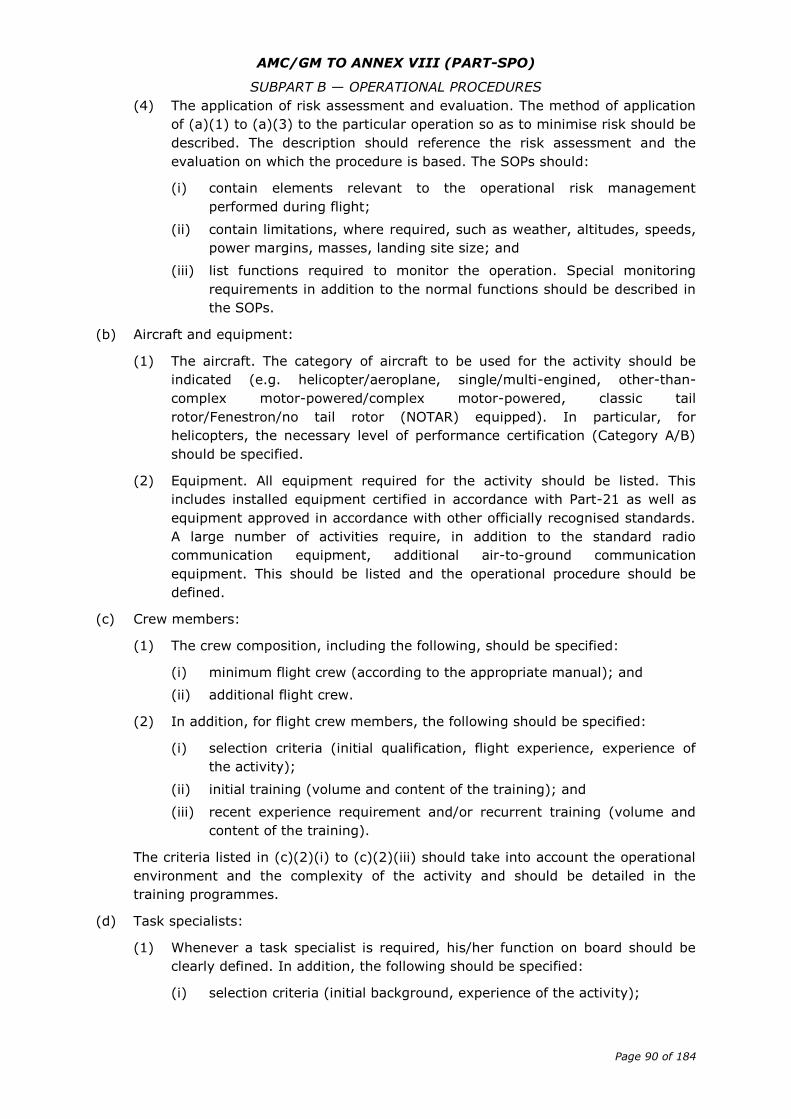
AMC/GM TO ANNEX VIII (PART-SPO)
SUBPART B — OPERATIONAL PROCEDURES
Page 90 of 184
(4) The application of risk assessment and evaluation. The method of application
of (a)(1) to (a)(3) to the particular operation so as to minimise risk should be
described. The description should reference the risk assessment and the
evaluation on which the procedure is based. The SOPs should:
(i) contain elements relevant to the operational risk management
performed during flight;
(ii) contain limitations, where required, such as weather, altitudes, speeds,
power margins, masses, landing site size; and
(iii) list functions required to monitor the operation. Special monitoring
requirements in addition to the normal functions should be described in
the SOPs.
(b) Aircraft and equipment:
(1) The aircraft. The category of aircraft to be used for the activity should be
indicated (e.g. helicopter/aeroplane, single/multi-engined, other-than-
complex motor-powered/complex motor-powered, classic tail
rotor/Fenestron/no tail rotor (NOTAR) equipped). In particular, for
helicopters, the necessary level of performance certification (Category A/B)
should be specified.
(2) Equipment. All equipment required for the activity should be listed. This
includes installed equipment certified in accordance with Part-21 as well as
equipment approved in accordance with other officially recognised standards.
A large number of activities require, in addition to the standard radio
communication equipment, additional air-to-ground communication
equipment. This should be listed and the operational procedure should be
defined.
(c) Crew members:
(1) The crew composition, including the following, should be specified:
(i) minimum flight crew (according to the appropriate manual); and
(ii) additional flight crew.
(2) In addition, for flight crew members, the following should be specified:
(i) selection criteria (initial qualification, flight experience, experience of
the activity);
(ii) initial training (volume and content of the training); and
(iii) recent experience requirement and/or recurrent training (volume and
content of the training).
The criteria listed in (c)(2)(i) to (c)(2)(iii) should take into account the operational
environment and the complexity of the activity and should be detailed in the
training programmes.
(d) Task specialists:
(1) Whenever a task specialist is required, his/her function on board should be
clearly defined. In addition, the following should be specified:
(i) selection criteria (initial background, experience of the activity);
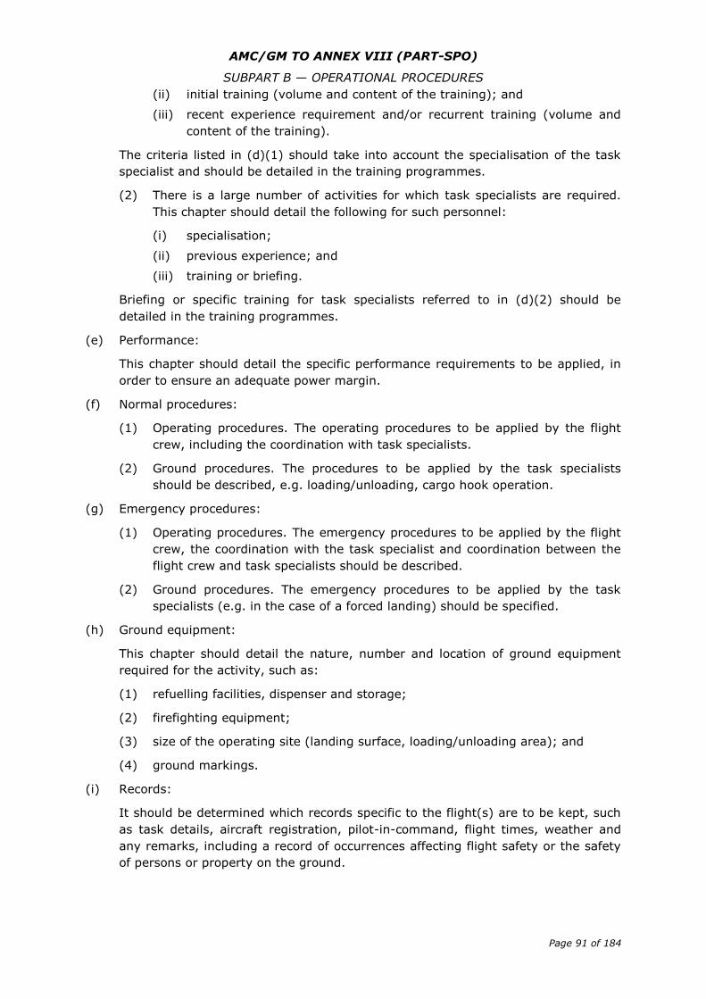
AMC/GM TO ANNEX VIII (PART-SPO)
SUBPART B — OPERATIONAL PROCEDURES
Page 91 of 184
(ii) initial training (volume and content of the training); and
(iii) recent experience requirement and/or recurrent training (volume and
content of the training).
The criteria listed in (d)(1) should take into account the specialisation of the task
specialist and should be detailed in the training programmes.
(2) There is a large number of activities for which task specialists are required.
This chapter should detail the following for such personnel:
(i) specialisation;
(ii) previous experience; and
(iii) training or briefing.
Briefing or specific training for task specialists referred to in (d)(2) should be
detailed in the training programmes.
(e) Performance:
This chapter should detail the specific performance requirements to be applied, in
order to ensure an adequate power margin.
(f) Normal procedures:
(1) Operating procedures. The operating procedures to be applied by the flight
crew, including the coordination with task specialists.
(2) Ground procedures. The procedures to be applied by the task specialists
should be described, e.g. loading/unloading, cargo hook operation.
(g) Emergency procedures:
(1) Operating procedures. The emergency procedures to be applied by the flight
crew, the coordination with the task specialist and coordination between the
flight crew and task specialists should be described.
(2) Ground procedures. The emergency procedures to be applied by the task
specialists (e.g. in the case of a forced landing) should be specified.
(h) Ground equipment:
This chapter should detail the nature, number and location of ground equipment
required for the activity, such as:
(1) refuelling facilities, dispenser and storage;
(2) firefighting equipment;
(3) size of the operating site (landing surface, loading/unloading area); and
(4) ground markings.
(i) Records:
It should be determined which records specific to the flight(s) are to be kept, such
as task details, aircraft registration, pilot-in-command, flight times, weather and
any remarks, including a record of occurrences affecting flight safety or the safety
of persons or property on the ground.

AMC/GM TO ANNEX VIII (PART-SPO)
SUBPART B — OPERATIONAL PROCEDURES
Page 92 of 184
GM1 SPO.OP.230 Standard operating procedures
TEMPLATE FORMS
Figure 1 — Development of a SOP based on a risk assessment
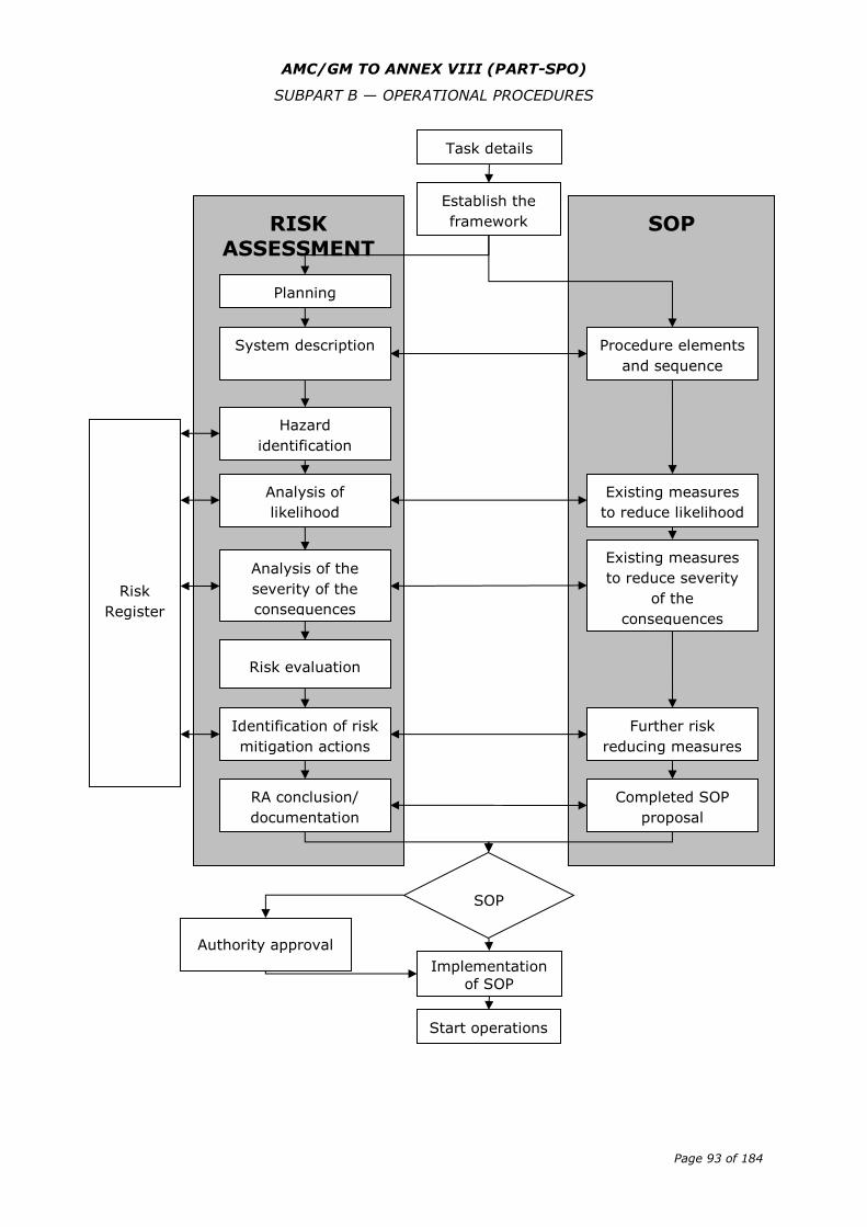
AMC/GM TO ANNEX VIII (PART-SPO)
SUBPART B — OPERATIONAL PROCEDURES
Page 93 of 184
SOP RISK ASSESSMENT
Task details
Establish the
framework
Planning
System description
Hazard
identification
Analysis of
likelihood
Analysis of the
severity of the
consequences
Risk evaluation
Identification of risk
mitigation actions
RA conclusion/
documentation
Implementation
of SOP
SOP
approva
Procedure elements
and sequence
Existing measures
to reduce likelihood
Existing measures
to reduce severity
of the
consequences
Further risk
reducing measures
Completed SOP
proposal
Authority approval
(if required)
Start operations
Risk
Register
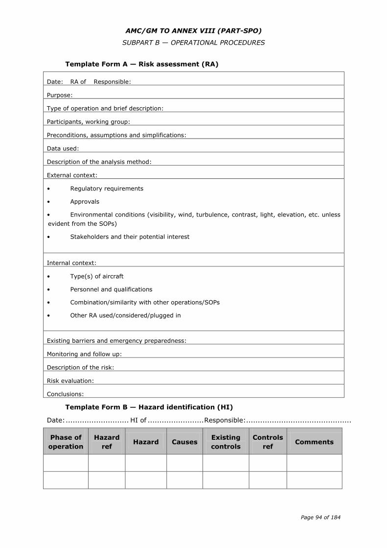
AMC/GM TO ANNEX VIII (PART-SPO)
SUBPART B — OPERATIONAL PROCEDURES
Page 94 of 184
Template Form A — Risk assessment (RA)
Date: RA of Responsible:
Purpose:
Type of operation and brief description:
Participants, working group:
Preconditions, assumptions and simplifications:
Data used:
Description of the analysis method:
External context:
• Regulatory requirements
• Approvals
• Environmental conditions (visibility, wind, turbulence, contrast, light, elevation, etc. unless
evident from the SOPs)
• Stakeholders and their potential interest
Internal context:
• Type(s) of aircraft
• Personnel and qualifications
• Combination/similarity with other operations/SOPs
• Other RA used/considered/plugged in
Existing barriers and emergency preparedness:
Monitoring and follow up:
Description of the risk:
Risk evaluation:
Conclusions:
Template Form B — Hazard identification (HI)
Date: ........................... HI of ........................ Responsible:.............................................
Phase of
operation
Hazard
ref Hazard Causes
Existing
controls
Controls
ref Comments
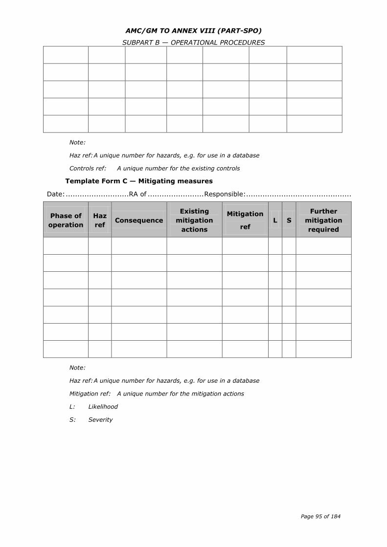
AMC/GM TO ANNEX VIII (PART-SPO)
SUBPART B — OPERATIONAL PROCEDURES
Page 95 of 184
Note:
Haz ref: A unique number for hazards, e.g. for use in a database
Controls ref: A unique number for the existing controls
Template Form C — Mitigating measures
Date: ........................... RA of ........................ Responsible:.............................................
Phase of
operation
Haz
ref Consequence
Existing
mitigation
actions
Mitigation
ref L S
Further
mitigation
required
Note:
Haz ref: A unique number for hazards, e.g. for use in a database
Mitigation ref: A unique number for the mitigation actions
L: Likelihood
S: Severity
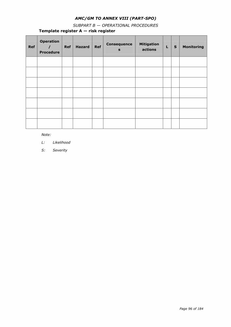
AMC/GM TO ANNEX VIII (PART-SPO)
SUBPART B — OPERATIONAL PROCEDURES
Page 96 of 184
Template register A — risk register
Ref
Operation
/
Procedure
Ref Hazard Ref Consequence
s
Mitigation
actions L S Monitoring
Note:
L: Likelihood
S: Severity
AMC/GM TO ANNEX VIII (PART-SPO)
SUBPART C — AIRCRAFT PERFORMANCE AND OPERATING LIMITATIONS
Page 97 of 184
Subpart C — Aircraft performance and operating limitations
AMC1 SPO.POL.100 Operating Limitations — all aircraft
APPROPRIATE MANUAL
The appropriate manual containing operating limitations may be the AFM or an
equivalent document, or the operations manual, if more restrictive.
GM1 SPO.POL.105 Mass and balance
GENERAL — OPERATIONS WITH OTHER-THAN-COMPLEX MOTOR-POWERED AIRCRAFT
(a) New aircraft that have been weighed at the factory may be placed into operation
without reweighing if the mass records and, except for balloons, balance records
have been adjusted for alterations or modifications to the aircraft. Aircraft
transferred from one EU operator to another EU operator do not have to be
weighed prior to use by the receiving operator unless the mass and balance cannot
be accurately established by calculation.
(b) For aircraft other than balloons, the mass and the centre of gravity (CG) position of
an aircraft should be revised whenever the cumulative changes to the dry
operating mass exceed ± 0.5 % of the maximum landing mass or for aeroplanes
the cumulative change in CG position exceeds 0.5 % of the mean aerodynamic
chord. This may be done by weighing the aircraft or by calculation. If the AFM
requires to record changes to mass and CG position below these thresholds, or to
record changes in any case, and make them known to the pilot-in-command, mass
and CG position should be revised accordingly and made known to the pilot-in-
command
(c) The initial empty mass for a balloon is the balloon empty mass determined by a
weighing performed by the manufacturer of the balloon before the initial entry into
service
(d) The mass of a balloon should be revised whenever the cumulative changes to the
balloon empty mass due to modifications or repairs exceed ± 10 % of the initial
empty mass. This may be done by weighing the balloon or by calculation.
AMC1 SPO.POL.105(b) Mass and balance
WEIGHING OF AN AIRCRAFT — OPERATIONS WITH COMPLEX MOTOR POWERED
AIRCRAFT
(a) New aircraft that have been weighed at the factory may be placed into operation
without reweighing if the mass and balance records have been adjusted for
alterations or modifications to the aircraft. Aircraft transferred from one EU
operator to another EU operator do not have to be weighed prior to use by the
receiving operator unless the mass and balance cannot be accurately established
by calculation.
(b) The mass and centre of gravity (CG) position of an aircraft should be revised
whenever the cumulative changes to the dry operating mass exceed ±0.5 % of the
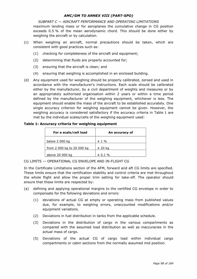
AMC/GM TO ANNEX VIII (PART-SPO)
SUBPART C — AIRCRAFT PERFORMANCE AND OPERATING LIMITATIONS
Page 98 of 184
maximum landing mass or for aeroplanes the cumulative change in CG position
exceeds 0.5 % of the mean aerodynamic chord. This should be done either by
weighing the aircraft or by calculation.
(c) When weighing an aircraft, normal precautions should be taken, which are
consistent with good practices such as:
(1) checking for completeness of the aircraft and equipment;
(2) determining that fluids are properly accounted for;
(3) ensuring that the aircraft is clean; and
(4) ensuring that weighing is accomplished in an enclosed building.
(d) Any equipment used for weighing should be properly calibrated, zeroed and used in
accordance with the manufacturer's instructions. Each scale should be calibrated
either by the manufacturer, by a civil department of weights and measures or by
an appropriately authorised organisation within 2 years or within a time period
defined by the manufacturer of the weighing equipment, whichever is less. The
equipment should enable the mass of the aircraft to be established accurately. One
single accuracy criterion for weighing equipment cannot be given. However, the
weighing accuracy is considered satisfactory if the accuracy criteria in Table 1 are
met by the individual scales/cells of the weighing equipment used:
Table 1: Accuracy criteria for weighing equipment
For a scale/cell load An accuracy of
below 2 000 kg ± 1 %
from 2 000 kg to 20 000 kg ± 20 kg
above 20 000 kg ± 0.1 %
CG LIMITS — OPERATIONAL CG ENVELOPE AND IN-FLIGHT CG
In the Certificate Limitations section of the AFM, forward and aft CG limits are specified.
These limits ensure that the certification stability and control criteria are met throughout
the whole flight and allow the proper trim setting for take-off. The operator should
ensure that these limits are respected by:
(a) defining and applying operational margins to the certified CG envelope in order to
compensate for the following deviations and errors:
(1) deviations of actual CG at empty or operating mass from published values
due, for example, to weighing errors, unaccounted modifications and/or
equipment variations.
(2) Deviations in fuel distribution in tanks from the applicable schedule.
(3) Deviations in the distribution of cargo in the various compartments as
compared with the assumed load distribution as well as inaccuracies in the
actual mass of cargo.
(5) Deviations of the actual CG of cargo load within individual cargo
compartments or cabin sections from the normally assumed mid position.
AMC/GM TO ANNEX VIII (PART-SPO)
SUBPART C — AIRCRAFT PERFORMANCE AND OPERATING LIMITATIONS
Page 99 of 184
(6) Deviations of the CG caused by gear and flap positions and by application of
the prescribed fuel usage procedure, unless already covered by the certified
limits.
(7) Deviations caused by in-flight movement of crew members and task
specialist.
(b) Defining and applying operational procedures in order to:
(1) take into account any significant CG travel during flight caused by persons
movement; and
(2) take into account any significant CG travel during flight caused by fuel
consumption/transfer.
AMC1 SPO.POL.110(a)(1) Mass and balance system — commercial operations
with aeroplanes and helicopters and non-commercial operations with complex
motor-powered aircraft
DRY OPERATING MASS
The dry operating mass should include:
(a) crew and equipment, and
(b) removable task specialist equipment, if applicable.
AMC1 SPO.POL.110(a)(2) Mass and balance system — commercial operations
with aeroplanes and helicopters and non-commercial operations with complex
motor-powered aircraft
SPECIAL STANDARD MASSES FOR TRAFFIC LOAD
The operator should use standard mass values for other load items. These standard
masses should be calculated on the basis of a detailed evaluation of the mass of the
items.
GM1 SPO.POL.110(a)(2) Mass and balance system — commercial operations
with aeroplanes and helicopters and non-commercial operations with complex
motor-powered aircraft
TRAFFIC LOAD
Traffic load includes task specialists.
AMC1 SPO.POL.110(a)(3) Mass and balance system — commercial operations
with aeroplanes and helicopters and non-commercial operations with complex
motor-powered aircraft
FUEL LOAD
The mass of the fuel load should be determined by using its actual relative density or a
standard relative density.
AMC/GM TO ANNEX VIII (PART-SPO)
SUBPART C — AIRCRAFT PERFORMANCE AND OPERATING LIMITATIONS
Page 100 of 184
GM1 SPO.POL.110(a)(3) Mass and balance system — commercial operations
with aeroplanes and helicopters and non-commercial operations with complex
motor-powered aircraft
FUEL DENSITY
(a) If the actual fuel density is not known, the operator may use standard fuel density
values for determining the mass of the fuel load. Such standard values should be
based on current fuel density measurements for the airports or areas concerned.
(b) Typical fuel density values are:
(1) Gasoline (piston engine fuel) – 0.71 ;
(2) JET A1 (Jet fuel JP 1) – 0.79 ;
(3) JET B (Jet fuel JP 4) – 0.76 ;
(4) Oil – 0.88.
AMC1 SPO.POL.110(a)(4) Mass and balance system — commercial operations
with aeroplanes and helicopters and non-commercial operations with complex
motor-powered aircraft
LOADING - STRUCTURAL LIMITS
The loading should take into account additional structural limits such as the floor
strength limitations, the maximum load per running metre, the maximum mass per
cargo compartment, and/or the maximum seating limits as well as in-flight changes in
loading.
GM1 SPO.POL.110(b) Mass and balance system — commercial operations with
aeroplanes and helicopters and non-commercial operations with complex
motor-powered aircraft
GENERAL
The mass and balance computation may be available in flight planning documents or
separate systems and may include standard load profiles.
AMC1 SPO.POL.115 Mass and balance data and documentation — commercial
operations with aeroplanes and helicopters and non-commercial operations
with complex motor-powered aircraft
GENERAL
(a) The mass and balance documentation should:
(1) enable the pilot-in-command to determine that the load and its distribution
are within the mass and balance limits of the aircraft; and
(2) include advise to the pilot-in-command whenever a non-standard method has
been used for determining the mass of the load.
(b) The information above may be available in flight planning documents or mass and
balance systems.
AMC/GM TO ANNEX VIII (PART-SPO)
SUBPART C — AIRCRAFT PERFORMANCE AND OPERATING LIMITATIONS
Page 101 of 184
(c) Any last minute change should be brought to the attention of the pilot-in-command
and entered in the flight planning documents containing the mass and balance
information and mass and balance systems.
(d) Where mass and balance documentation is generated by a computerised mass and
balance system, the operator should verify the integrity of the output data at
intervals not exceeding six months.
(e) A copy of the final mass and balance documentation may be sent to aircraft via
data link or may be made available to the pilot-in–command by other means for its
acceptance.
(f) The person supervising the loading of the aircraft should confirm by hand signature
or equivalent that the load and its distribution are in accordance with the mass and
balance documentation given to the pilot in command. The pilot-in-command
should indicate his acceptance by hand signature or equivalent.
GM1 SPO.POL.115 Mass and balance data and documentation — commercial
operations with aeroplanes and helicopters and non-commercial operations
with complex motor-powered aircraft
SIGNATURE OR EQUIVALENT
Where a signature by hand is impracticable or it is desirable to arrange the equivalent
verification by electronic means, as referred to in AMC1 SPO.POL.115 (f), the following
conditions should be applied in order to make an electronic signature the equivalent of a
conventional hand-written signature:
(a) electronic ‘signing’ by entering a personal identification number (PIN) code with
appropriate security, etc.;
(b) entering the PIN code generates a print-out of the individual’s name and
professional capacity on the relevant document(s) in such a way that it is evident,
to anyone having a need for that information, who has signed the document;
(c) the computer system logs information to indicate when and where each PIN code
has been entered;
(d) the use of the PIN code is, from a legal and responsibility point of view, considered
to be fully equivalent to signature by hand;
(e) the requirements for record keeping remain unchanged; and
(f) all personnel concerned are made aware of the conditions associated with
electronic signature and this is documented.
AMC1 SPO.POL.115(b) Mass and balance data and documentation —
commercial operations with aeroplanes and helicopters and non-commercial
operations with complex motor-powered aircraft
INTEGRITY
The operator should verify the integrity of mass and balance data and documentation
generated by a computerised mass and balance system, at intervals not exceeding
six months. The operator should establish a system to check that amendments of its
input data are incorporated properly in the system and that the system is operating
correctly on a continuous basis.
AMC/GM TO ANNEX VIII (PART-SPO)
SUBPART C — AIRCRAFT PERFORMANCE AND OPERATING LIMITATIONS
Page 102 of 184
AMC2 SPO.POL.115(b) Mass and balance data and documentation —
commercial operations with aeroplanes and helicopters and non-commercial
operations with complex motor-powered aircraft
MASS AND BALANCE DOCUMENTATION SENT VIA DATA LINK
Whenever the mass and balance documentation is sent to the aircraft via data link, a
copy of the final mass and balance documentation as accepted by the pilot-in-command
should be available on the ground.
GM1 SPO.POL.115(b) Mass and balance data and documentation — commercial
operations with aeroplanes and helicopters and non-commercial operations
with complex motor-powered aircraft
ON BOARD INTEGRATED MASS AND BALANCE COMPUTER SYSTEM
An on-board integrated mass and balance computer system may be an aircraft installed
system capable of receiving input data either from other aircraft systems or from a mass
and balance system on ground, in order to generate mass and balance data as an
output.
GM2 SPO.POL.115(b) Mass and balance data and documentation — commercial
operations with aeroplanes and helicopters and non-commercial operations
with complex motor-powered aircraft
STAND-ALONE COMPUTERISED MASS AND BALANCE SYSTEM
A stand-alone computerised mass and balance system may be a computer, either as part
of an electronic flight bag (EFB) system or solely dedicated to mass and balance
purposes, requiring input from the user, in order to generate mass and balance data as
an output.
AMC1 SPO.POL.130(a) Take-off — complex motor-powered aeroplanes
TAKE-OFF MASS
The following should be considered for determining the maximum take-off mass:
(a) the pressure altitude at the aerodrome;
(b) the ambient temperature at the aerodrome;
(c) the runway surface condition and the type of runway surface;
(d) the runway slope in the direction of take-off;
(e) not more than 50 % of the reported head-wind component or not less than 150 %
of the reported tailwind component; and
(f) the loss, if any, of runway length due to alignment of the aeroplane prior to take-
off.
AMC1 SPO.POL.130(a)(4) Take-off — complex motor-powered aeroplanes
CONTAMINATED RUNWAY PERFORMANCE DATA
Wet and contaminated runway performance data, if made available by the manufacturer,
should be taken into account. If such data is not made available, the operator should
AMC/GM TO ANNEX VIII (PART-SPO)
SUBPART C — AIRCRAFT PERFORMANCE AND OPERATING LIMITATIONS
Page 103 of 184
account for wet and contaminated runway conditions by using the best information
available.
GM1 SPO.POL.130(a)(4) Take-off — complex motor-powered aeroplanes
RUNWAY SURFACE CONDITION
Operation on runways contaminated with water, slush, snow or ice implies uncertainties
with regard to runway friction and contaminant drag and therefore to the achievable
performance and control of the aeroplane during take-off or landing, since the actual
conditions may not completely match the assumptions on which the performance
information is based. In the case of a contaminated runway, the first option for the pilot-
in-command is to wait until the runway is cleared. If this is impracticable, he/she may
consider a take-off or landing, provided that he/she has applied the applicable
performance adjustments, and any further safety measures he/she considers justified
under the prevailing conditions. The excess runway length available including the
criticality of the overrun area should also be considered.
AMC1 SPO.POL.130(b)(2) Take-off — complex motor-powered aeroplanes
ADEQUATE MARGIN
The adequate margin should be defined in the operations manual.
GM1 SPO.POL.130(b)(2) Take-off — complex motor-powered aeroplanes
ADEQUATE MARGIN
`An adequate margin` is illustrated by the appropriate examples included in Attachment
C to ICAO Annex 6, Part I.
AMC1 SPO.POL.140 Landing — complex motor-powered aeroplanes
GENERAL
The following should be considered to ensure that an aeroplane is able to land and stop,
or a seaplane to come to a satisfactorily low speed, within the landing distance available:
(a) the pressure altitude at the aerodrome;
(b) the runway surface condition and the type of runway surface;
(C) the runway slope in the direction of landing;
(d) not more than 50 % of the reported head-wind component or not less than 150 %
of the reported tailwind component;
(e) use of the most favourable runway, in still air; and
(f) use of the runway most likely to be assigned considering the probable wind speed
and direction and the ground handling characteristics of the aeroplane, and
considering other conditions such as landing aids and terrain.
AMC2 SPO.POL.140 Landing — complex motor-powered aeroplanes
ALLOWANCES
Allowances should be stated in the operations manual.
AMC/GM TO ANNEX VIII (PART-SPO)
SUBPART C — AIRCRAFT PERFORMANCE AND OPERATING LIMITATIONS
Page 104 of 184
AMC1 SPO.POL.145(a) and (b) Performance and operating criteria —
aeroplanes, and
AMC1 SPO.POL.146(b)(1) and (2) Performance and operating criteria —
helicopters
OPERATIONAL PROCEDURES AND TRAINING PROGRAMME
(a) The operational procedures should be based on the manufacturer’s recommended
procedures where they exist.
(b) The crew member training programme should include briefing, demonstration or
practice, as appropriate, of the operational procedures necessary to minimise the
consequences of an engine failure.
AMC1 SPO.POL.146(c) Performance and operating criteria — helicopters
MAXIMUM SPECIFIED MASSES
(a) The operator should establish a procedure to determine maximum specified masses
for HIGE and HOGE before each flight or series of flights.
(b) This procedure should take into account ambient temperature at the aerodrome or
operating site, pressure altitude and wind conditions data available.
GM1 SPO.POL.146(c) Performance and operating criteria — helicopters
GENERAL
(a) Even when the surface allows a hover in ground effect (HIGE), the likelihood of, for
example, dust or blowing snow may necessitate hover out of ground effect (HOGE)
performance.
(b) Wind conditions on some sites (particularly in mountainous areas and including
downdraft) may require a reduction in the helicopter mass in order to ensure that
an out of ground effect hover can be achieved at the operational site in the
conditions prevailing.
AMC/GM TO ANNEX VIII (PART-SPO)
SUBPART D — INSTRUMENTS, DATA AND EQUIPMENT
Page 105 of 184
Subpart D — Instruments, data and equipment
Section 1 — Aeroplanes
GM1 SPO.IDE.A.100(a) Instruments and equipment — general
APPLICABLE AIRWORTHINESS REQUIREMENTS
The applicable airworthiness requirements for approval of instruments and equipment
required by this Part are the following:
(a) Commission Regulation (EU) No 748/20126 for aeroplanes registered in the EU;
and
(b) Airworthiness requirements of the State of registry for aeroplanes registered
outside the EU.
GM1 SPO.IDE.A.100(b) Instruments and equipment — general
REQUIRED INSTRUMENTS AND EQUIPMENT THAT DO NOT NEED TO BE APPROVED IN
ACCORDANCE WITH THE APPLICABLE AIRWORTHINESS REQUIREMENTS
The functionality of non-installed instruments and equipment required by this Subpart
and that do not need an equipment approval, as listed in SPO.IDE.A.100(b), should be
checked against recognised industry standards appropriate to the intended purpose. The
operator is responsible for ensuring the maintenance of these instruments and
equipment.
GM1 SPO.IDE.A.100(c) Instruments and equipment — general
NOT REQUIRED INSTRUMENTS AND EQUIPMENT THAT DO NOT NEED TO BE APPROVED
IN ACCORDANCE WITH THE APPLICABLE AIRWORTHINESS REQUIREMENTS, BUT ARE
CARRIED ON A FLIGHT
(a) The provision of this paragraph does not exempt any installed instrument or item
of equipment from complying with the applicable airworthiness requirements. In
this case, the installation should be approved as required in the applicable
airworthiness requirements and should comply with the applicable airworthiness
codes.
(b) The failure of additional non-installed instruments or equipment not required by
this Part or by the applicable airworthiness requirements or any applicable airspace
requirements should not adversely affect the airworthiness and/or the safe
operation of the aeroplane. Examples may be the following:
(1) portable electronic flight bag (EFB);
6 Commission Regulation (EU) No 748/2012 of 3 August 2012 laying down implementing rules for
the airworthiness and environmental certification of aircraft and related products, parts and appliances, as well as for the certification of design and production organisations, (OJ L 224, 21.8.2012, p. 1).
AMC/GM TO ANNEX VIII (PART-SPO)
SUBPART D — INSTRUMENTS, DATA AND EQUIPMENT
Page 106 of 184
(2) portable electronic devices carried by crew members or task specialists; and
(3) non-installed task specialist equipment.
GM1 SPO.IDE.A.100(d) Instruments and equipment — general
POSITIONING OF INSTRUMENTS
This requirement implies that whenever a single instrument is required in an aeroplane
operated in a multi-crew environment, the instrument needs to be visible from each
flight crew station.
GM1 SPO.IDE.A.110 Spare electrical fuses
FUSES
A spare electrical fuse means a replaceable fuse in the flight crew compartment, not an
automatic circuit breaker or circuit breakers in the electric compartments.
AMC1 SPO.IDE.A.120 & SPO.IDE.A.125 Operations under VFR & operations
under IFR — flight and navigational instruments and associated equipment
INTEGRATED INSTRUMENTS
(a) Individual equipment requirements may be met by combinations of instruments, by
integrated flight systems or by a combination of parameters on electronic displays.
The information so available to each required pilot should not be less than that
required in the applicable operational requirements, and the equivalent safety of
the installation should be approved during type certification of the aeroplane for
the intended type of operation.
(b) The means of measuring and indicating turn and slip, aeroplane attitude and
stabilised aeroplane heading may be met by combinations of instruments or by
integrated flight director systems, provided that the safeguards against total
failure, inherent in the three separate instruments, are retained.
AMC2 SPO.IDE.A.120 Operations under VFR — flight and navigational
instruments and associated equipment
LOCAL FLIGHTS
For flights that do not exceed 60 minutes’ duration, that take off and land at the same
aerodrome, and that remain within 50 NM of that aerodrome, an equivalent means of
complying with SPO.IDE.A.120 (b)(1)(i), (b)(1)(ii) may be:
(a) a turn and slip indicator;
(b) a turn co-ordinator; or
(c) both an attitude indicator and a slip indicator.
AMC/GM TO ANNEX VIII (PART-SPO)
SUBPART D — INSTRUMENTS, DATA AND EQUIPMENT
Page 107 of 184
GM1 SPO.IDE.A.120 Operations under VFR — flight and navigational
instruments and associated equipment
SLIP INDICATION
Non-complex motor-powered aeroplanes should be equipped with a means of measuring
and displaying slip.
GM1 SPO.IDE.A.125 Operations under IFR — flight and navigational
instruments and associated equipment
ALTERNATE SOURCE OF STATIC PRESSURE
Aeroplanes should be equipped with an alternate source of static pressure.
AMC1 SPO.IDE.A.120(a)(1) & SPO.IDE.A.125(a)(1) Operations under VFR &
operations under IFR — flight and navigational instruments and associated
equipment
MEANS OF MEASURING AND DISPLAYING MAGNETIC HEADING
The means of measuring and displaying magnetic direction should be a magnetic
compass or equivalent.
AMC1 SPO.IDE.A.120(a)(2) & SPO.IDE.A.125(a)(2) Operations under VFR &
operations under IFR — flight and navigational instruments and associated
equipment
MEANS OF MEASURING AND DISPLAYING THE TIME — COMPLEX MOTOR-POWERED
AIRCRAFT
An acceptable means of compliance is a clock displaying hours, minutes and seconds,
with a sweep-second pointer or digital presentation.
MEANS OF MEASURING AND DISPLAYING THE TIME — OTHER-THAN- COMPLEX MOTOR-
POWERED AIRCRAFT
An acceptable means of measuring and displaying the time in hours, minutes and
seconds may be a wrist watch capable of the same functions.
AMC1 SPO.IDE.A.120(a)(3) & SPO.IDE.A.125(a)(3) Operations under VFR
operations & operations under IFR — flight and navigational instruments and
associated equipment
CALIBRATION OF THE MEANS OF MEASURING AND DISPLAYING PRESSURE ALTITUDE
The instrument measuring and displaying pressure altitude should be of a sensitive type
calibrated in feet (ft), with a sub-scale setting, calibrated in hectopascals/millibars,
adjustable for any barometric pressure likely to be set during flight.
AMC/GM TO ANNEX VIII (PART-SPO)
SUBPART D — INSTRUMENTS, DATA AND EQUIPMENT
Page 108 of 184
GM1 SPO.IDE.A.125(a)(3) Operations under IFR — flight and navigational
instruments and associated equipment
ALTIMETERS
Altimeters with counter drum-pointer or equivalent presentation are considered to be
less susceptible to misinterpretation for aeroplanes operating above 10 000 ft.
AMC1 SPO.IDE.A.120(a)(4) & SPO.IDE.A.125(a)(4) Operations under VFR &
operations under IFR — flight and navigational instruments and associated
equipment
CALIBRATION OF THE INSTRUMENT INDICATING AIRSPEED
(a) The instrument indicating airspeed should be calibrated in knots (kt).
(b) In the case of aeroplanes with a maximum certified take-off mass (MCTOM) below
2 000 kg, calibration in kilometres (km) per hour or in miles per hour (mph) is
acceptable when such units are used in the AFM.
AMC1 SPO.IDE.A.120(e) & SPO.IDE.A.125(c) Operations under VFR &
operations under IFR — flight and navigational instruments and associated
equipment
MULTI-PILOT OPERATIONS — DUPLICATE INSTRUMENTS
Duplicate instruments include separate displays for each pilot and separate selectors or
other associated equipment where appropriate.
AMC1 SPO.IDE.A.125(a)(9) Operations under IFR — flight and navigational
instruments and associated equipment
MEANS OF DISPLAYING OUTSIDE AIR TEMPERATURE
(a) The means of displaying outside air temperature should be calibrated in degrees
Celsius.
(b) In the case of aeroplanes with a maximum certified take-off mass (MCTOM) below
2 000 kg, calibration in degrees Fahrenheit is acceptable, when such unit is used in
the AFM.
(c) The means of displaying outside air temperature may be an air temperature
indicator that provides indications that are convertible to outside air temperature.
AMC1 SPO.IDE.A.120(c) & SPO.IDE.A.125(d) Operations under VFR &
operations under IFR — flight and navigational instruments and associated
equipment
MEANS OF PREVENTING MALFUNCTION DUE TO CONDENSATION OR ICING
The means of preventing malfunction due to either condensation or icing of the airspeed
indicating system should be a heated pitot tube or equivalent.
AMC/GM TO ANNEX VIII (PART-SPO)
SUBPART D — INSTRUMENTS, DATA AND EQUIPMENT
Page 109 of 184
AMC1 SPO.IDE.A.125(e)(2) Operations under IFR — flight and navigational
instruments and associated equipment
CHART HOLDER
An acceptable means of compliance with the chart holder requirement for complex
motor-powered aeroplanes is to display a pre-composed chart on an electronic flight bag
(EFB).
AMC1 SPO.IDE.A.130 Terrain awareness warning system (TAWS)
EXCESSIVE DOWNWARDS GLIDESLOPE DEVIATION WARNING FOR CLASS A TAWS
The requirement for a Class A TAWS to provide a warning to the flight crew for excessive
downwards glideslope deviation should apply to all final approach glideslopes with
angular vertical navigation (VNAV) guidance, whether provided by the instrument
landing system (ILS), microwave landing system (MLS), satellite-based augmentation
system approach procedure with vertical guidance (SBAS APV (localiser performance
with vertical guidance approach LPV)), ground-based augmentation system (GBAS (GPS
landing system, GLS)) or any other systems providing similar guidance. The same
requirement should not apply to systems providing vertical guidance based on
barometric VNAV.
GM1 SPO.IDE.A.130 Terrain awareness warning system (TAWS)
ACCEPTABLE STANDARD FOR TAWS
An acceptable standard for Class A and Class B TAWS may be the applicable European
Technical Standards Order (ETSO) issued by the Agency or equivalent.
AMC1 SPO.IDE.A.132 Airborne weather detecting equipment — complex
motor-powered aeroplanes
GENERAL
The airborne weather detecting equipment should be an airborne weather radar.
However, for propeller-driven pressurised aeroplanes with an MCTOM not more than
5 700 kg and an maximum certified seating configuration of not more than nine, other
equipment capable of detecting thunderstorms and other potentially hazardous weather
conditions, regarded as detectable with airborne weather radar equipment, are also
acceptable.
AMC1 SPO.IDE.A.135 Flight crew interphone system
TYPE OF FLIGHT CREW INTERPHONE
The flight crew interphone system should not be of a handheld type.
AMC1 SPO.IDE.A.140 Cockpit voice recorder
GENERAL
The operational performance requirements for cockpit voice recorders (CVRs) should be
those laid down in the European Organisation for Civil Aviation Equipment (EUROCAE)
Document ED-112 (Minimum Operational Performance Specification for Crash Protected
AMC/GM TO ANNEX VIII (PART-SPO)
SUBPART D — INSTRUMENTS, DATA AND EQUIPMENT
Page 110 of 184
Airborne Recorder Systems), dated March 2003, including amendments No 1 and No 2,
or any later equivalent standard produced by EUROCAE.
AMC1 SPO.IDE.A.145 Flight data recorder
OPERATIONAL PERFORMANCE REQUIREMENTS
(a) The operational performance requirements for flight data recorders (FDRs) should
be those laid down in EUROCAE Document ED-112 (Minimum Operational
Performance Specification for Crash Protected Airborne Recorder Systems) dated
March 2003, including amendments No 1 and No 2, or any later equivalent
standard produced by EUROCAE.
(b) The flight data recorder should record, with reference to a timescale, the list of
parameters in Table 1 and Table 2, as applicable.
(c) The parameters to be recorded should meet the performance specifications
(designated ranges, sampling intervals, accuracy limits and minimum resolution in
read-out) as defined in the relevant tables of EUROCAE Document ED-112
(Minimum Operational Performance Specification for Crash Protected Airborne
Recorder Systems), dated March 2003, including amendments No 1 and No 2, or
any later equivalent standard produced by EUROCAE.
Table 1: All Aeroplanes
No* Parameter
1a
1b
1c
Time; or
Relative time count
Global navigation satellite system (GNSS) time synchronisation
2 Pressure altitude
3 Indicated airspeed; or calibrated airspeed
4 Heading (primary flight crew reference) — when true or magnetic heading can
be selected, the primary heading reference, a discrete indicating selection,
should be recorded
5 Normal acceleration
6 Pitch attitude
7 Roll attitude
8 Manual radio transmission keying and CVR/FDR synchronisation reference.
9
9a
9b
Engine thrust/power
Parameters required to determine propulsive thrust/power on each engine
Flight crew compartment thrust/power lever position for aeroplanes with no
mechanical link between engine and flight crew compartment))
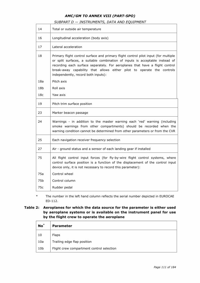
AMC/GM TO ANNEX VIII (PART-SPO)
SUBPART D — INSTRUMENTS, DATA AND EQUIPMENT
Page 111 of 184
14 Total or outside air temperature
16 Longitudinal acceleration (body axis)
17 Lateral acceleration
18
18a
18b
18c
Primary flight control surface and primary flight control pilot input (for multiple
or split surfaces, a suitable combination of inputs is acceptable instead of
recording each surface separately. For aeroplanes that have a flight control
break-away capability that allows either pilot to operate the controls
independently, record both inputs):
Pitch axis
Roll axis
Yaw axis
19 Pitch trim surface position
23 Marker beacon passage
24 Warnings - in addition to the master warning each ‘red’ warning (including
smoke warnings from other compartments) should be recorded when the
warning condition cannot be determined from other parameters or from the CVR
25 Each navigation receiver frequency selection
27 Air - ground status and a sensor of each landing gear if installed
75
75a
75b
75c
All flight control input forces (for fly-by-wire flight control systems, where
control surface position is a function of the displacement of the control input
device only, it is not necessary to record this parameter):
Control wheel
Control column
Rudder pedal
* The number in the left hand column reflects the serial number depicted in EUROCAE
ED-112.
Table 2: Aeroplanes for which the data source for the parameter is either used
by aeroplane systems or is available on the instrument panel for use
by the flight crew to operate the aeroplane
No* Parameter
10
10a
10b
Flaps
Trailing edge flap position
Flight crew compartment control selection
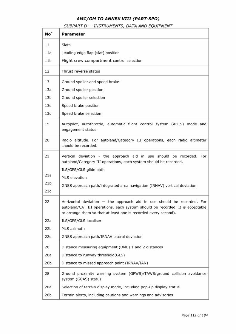
AMC/GM TO ANNEX VIII (PART-SPO)
SUBPART D — INSTRUMENTS, DATA AND EQUIPMENT
Page 112 of 184
No* Parameter
11
11a
11b
Slats
Leading edge flap (slat) position
Flight crew compartment control selection
12 Thrust reverse status
13
13a
13b
13c
13d
Ground spoiler and speed brake:
Ground spoiler position
Ground spoiler selection
Speed brake position
Speed brake selection
15 Autopilot, autothrottle, automatic flight control system (AFCS) mode and
engagement status
20 Radio altitude. For autoland/Category III operations, each radio altimeter
should be recorded.
21
21a
21b
21c
Vertical deviation - the approach aid in use should be recorded. For
autoland/Category III operations, each system should be recorded.
ILS/GPS/GLS glide path
MLS elevation
GNSS approach path/integrated area navigation (IRNAV) vertical deviation
22
22a
22b
22c
Horizontal deviation — the approach aid in use should be recorded. For
autoland/CAT III operations, each system should be recorded. It is acceptable
to arrange them so that at least one is recorded every second).
ILS/GPS/GLS localiser
MLS azimuth
GNSS approach path/IRNAV lateral deviation
26
26a
26b
Distance measuring equipment (DME) 1 and 2 distances
Distance to runway threshold(GLS)
Distance to missed approach point (IRNAV/IAN)
28
28a
28b
Ground proximity warning system (GPWS)/TAWS/ground collision avoidance
system (GCAS) status:
Selection of terrain display mode, including pop-up display status
Terrain alerts, including cautions and warnings and advisories
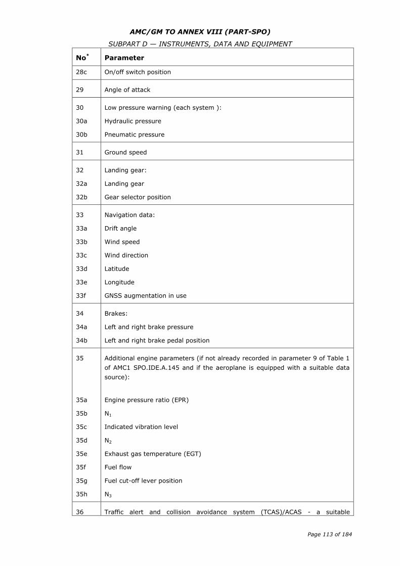
AMC/GM TO ANNEX VIII (PART-SPO)
SUBPART D — INSTRUMENTS, DATA AND EQUIPMENT
Page 113 of 184
No* Parameter
28c On/off switch position
29 Angle of attack
30
30a
30b
Low pressure warning (each system ):
Hydraulic pressure
Pneumatic pressure
31 Ground speed
32
32a
32b
Landing gear:
Landing gear
Gear selector position
33
33a
33b
33c
33d
33e
33f
Navigation data:
Drift angle
Wind speed
Wind direction
Latitude
Longitude
GNSS augmentation in use
34
34a
34b
Brakes:
Left and right brake pressure
Left and right brake pedal position
35
35a
35b
35c
35d
35e
35f
35g
35h
Additional engine parameters (if not already recorded in parameter 9 of Table 1
of AMC1 SPO.IDE.A.145 and if the aeroplane is equipped with a suitable data
source):
Engine pressure ratio (EPR)
N1
Indicated vibration level
N2
Exhaust gas temperature (EGT)
Fuel flow
Fuel cut-off lever position
N3
36 Traffic alert and collision avoidance system (TCAS)/ACAS - a suitable
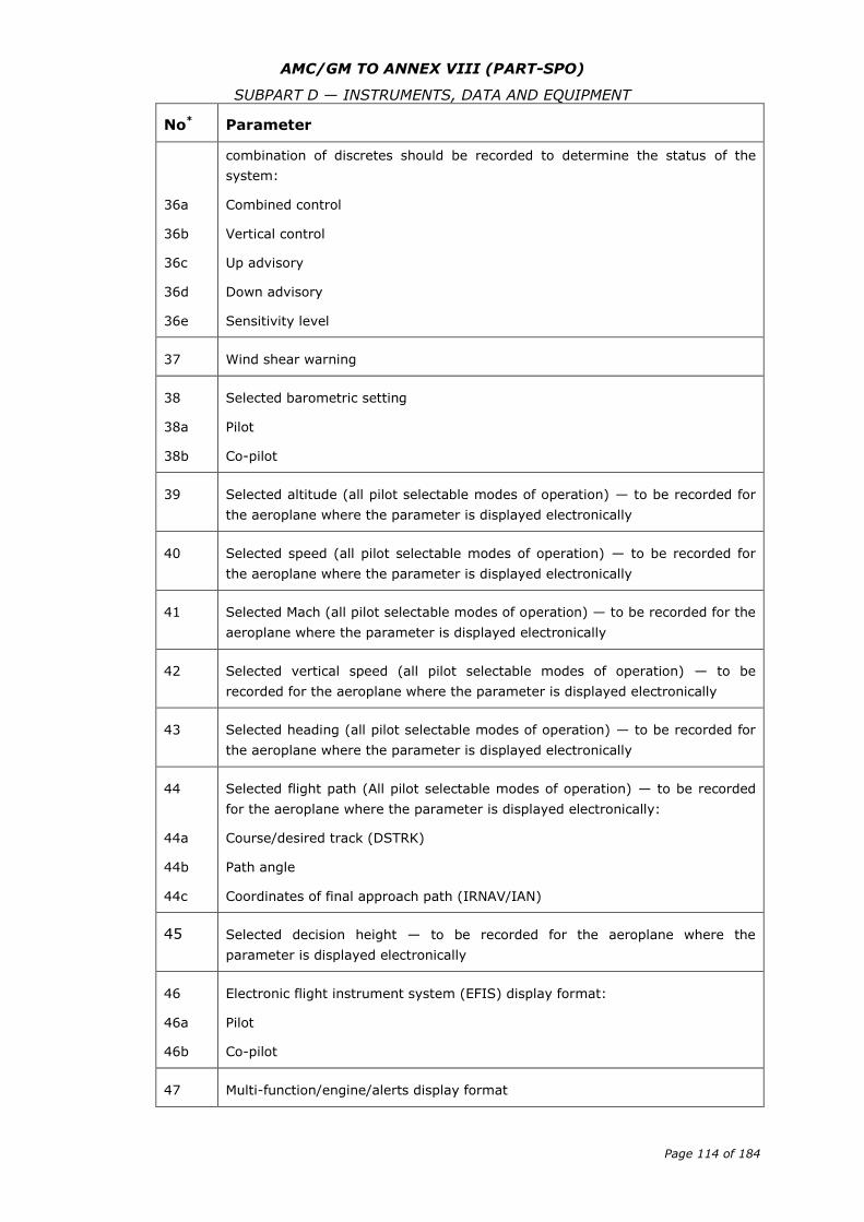
AMC/GM TO ANNEX VIII (PART-SPO)
SUBPART D — INSTRUMENTS, DATA AND EQUIPMENT
Page 114 of 184
No* Parameter
36a
36b
36c
36d
36e
combination of discretes should be recorded to determine the status of the
system:
Combined control
Vertical control
Up advisory
Down advisory
Sensitivity level
37 Wind shear warning
38
38a
38b
Selected barometric setting
Pilot
Co-pilot
39 Selected altitude (all pilot selectable modes of operation) — to be recorded for
the aeroplane where the parameter is displayed electronically
40 Selected speed (all pilot selectable modes of operation) — to be recorded for
the aeroplane where the parameter is displayed electronically
41 Selected Mach (all pilot selectable modes of operation) — to be recorded for the
aeroplane where the parameter is displayed electronically
42 Selected vertical speed (all pilot selectable modes of operation) — to be
recorded for the aeroplane where the parameter is displayed electronically
43 Selected heading (all pilot selectable modes of operation) — to be recorded for
the aeroplane where the parameter is displayed electronically
44
44a
44b
44c
Selected flight path (All pilot selectable modes of operation) — to be recorded
for the aeroplane where the parameter is displayed electronically:
Course/desired track (DSTRK)
Path angle
Coordinates of final approach path (IRNAV/IAN)
45 Selected decision height — to be recorded for the aeroplane where the
parameter is displayed electronically
46
46a
46b
Electronic flight instrument system (EFIS) display format:
Pilot
Co-pilot
47 Multi-function/engine/alerts display format
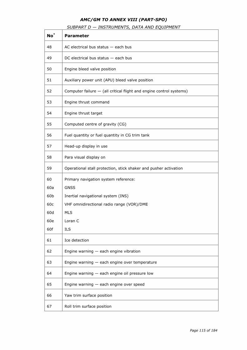
AMC/GM TO ANNEX VIII (PART-SPO)
SUBPART D — INSTRUMENTS, DATA AND EQUIPMENT
Page 115 of 184
No* Parameter
48 AC electrical bus status — each bus
49 DC electrical bus status — each bus
50 Engine bleed valve position
51 Auxiliary power unit (APU) bleed valve position
52 Computer failure — (all critical flight and engine control systems)
53 Engine thrust command
54 Engine thrust target
55 Computed centre of gravity (CG)
56 Fuel quantity or fuel quantity in CG trim tank
57 Head-up display in use
58 Para visual display on
59 Operational stall protection, stick shaker and pusher activation
60
60a
60b
60c
60d
60e
60f
Primary navigation system reference:
GNSS
Inertial navigational system (INS)
VHF omnidirectional radio range (VOR)/DME
MLS
Loran C
ILS
61 Ice detection
62 Engine warning — each engine vibration
63 Engine warning — each engine over temperature
64 Engine warning — each engine oil pressure low
65 Engine warning — each engine over speed
66 Yaw trim surface position
67 Roll trim surface position
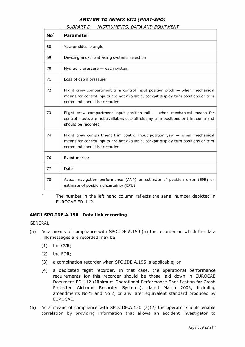
AMC/GM TO ANNEX VIII (PART-SPO)
SUBPART D — INSTRUMENTS, DATA AND EQUIPMENT
Page 116 of 184
No* Parameter
68 Yaw or sideslip angle
69 De-icing and/or anti-icing systems selection
70 Hydraulic pressure — each system
71 Loss of cabin pressure
72 Flight crew compartment trim control input position pitch — when mechanical
means for control inputs are not available, cockpit display trim positions or trim
command should be recorded
73 Flight crew compartment input position roll — when mechanical means for
control inputs are not available, cockpit display trim positions or trim command
should be recorded
74 Flight crew compartment trim control input position yaw — when mechanical
means for control inputs are not available, cockpit display trim positions or trim
command should be recorded
76 Event marker
77 Date
78 Actual navigation performance (ANP) or estimate of position error (EPE) or
estimate of position uncertainty (EPU)
* The number in the left hand column reflects the serial number depicted in
EUROCAE ED-112.
AMC1 SPO.IDE.A.150 Data link recording
GENERAL
(a) As a means of compliance with SPO.IDE.A.150 (a) the recorder on which the data
link messages are recorded may be:
(1) the CVR;
(2) the FDR;
(3) a combination recorder when SPO.IDE.A.155 is applicable; or
(4) a dedicated flight recorder. In that case, the operational performance
requirements for this recorder should be those laid down in EUROCAE
Document ED-112 (Minimum Operational Performance Specification for Crash
Protected Airborne Recorder Systems), dated March 2003, including
amendments No°1 and No 2, or any later equivalent standard produced by
EUROCAE.
(b) As a means of compliance with SPO.IDE.A.150 (a)(2) the operator should enable
correlation by providing information that allows an accident investigator to
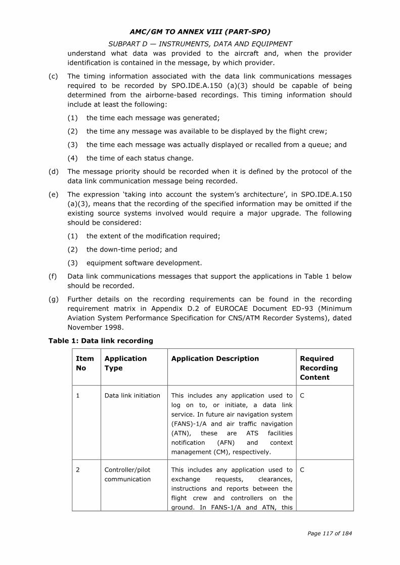
AMC/GM TO ANNEX VIII (PART-SPO)
SUBPART D — INSTRUMENTS, DATA AND EQUIPMENT
Page 117 of 184
understand what data was provided to the aircraft and, when the provider
identification is contained in the message, by which provider.
(c) The timing information associated with the data link communications messages
required to be recorded by SPO.IDE.A.150 (a)(3) should be capable of being
determined from the airborne-based recordings. This timing information should
include at least the following:
(1) the time each message was generated;
(2) the time any message was available to be displayed by the flight crew;
(3) the time each message was actually displayed or recalled from a queue; and
(4) the time of each status change.
(d) The message priority should be recorded when it is defined by the protocol of the
data link communication message being recorded.
(e) The expression ‘taking into account the system’s architecture’, in SPO.IDE.A.150
(a)(3), means that the recording of the specified information may be omitted if the
existing source systems involved would require a major upgrade. The following
should be considered:
(1) the extent of the modification required;
(2) the down-time period; and
(3) equipment software development.
(f) Data link communications messages that support the applications in Table 1 below
should be recorded.
(g) Further details on the recording requirements can be found in the recording
requirement matrix in Appendix D.2 of EUROCAE Document ED-93 (Minimum
Aviation System Performance Specification for CNS/ATM Recorder Systems), dated
November 1998.
Table 1: Data link recording
Item
No
Application
Type
Application Description Required
Recording
Content
1 Data link initiation This includes any application used to
log on to, or initiate, a data link
service. In future air navigation system
(FANS)-1/A and air traffic navigation
(ATN), these are ATS facilities
notification (AFN) and context
management (CM), respectively.
C
2 Controller/pilot
communication
This includes any application used to
exchange requests, clearances,
instructions and reports between the
flight crew and controllers on the
ground. In FANS-1/A and ATN, this
C
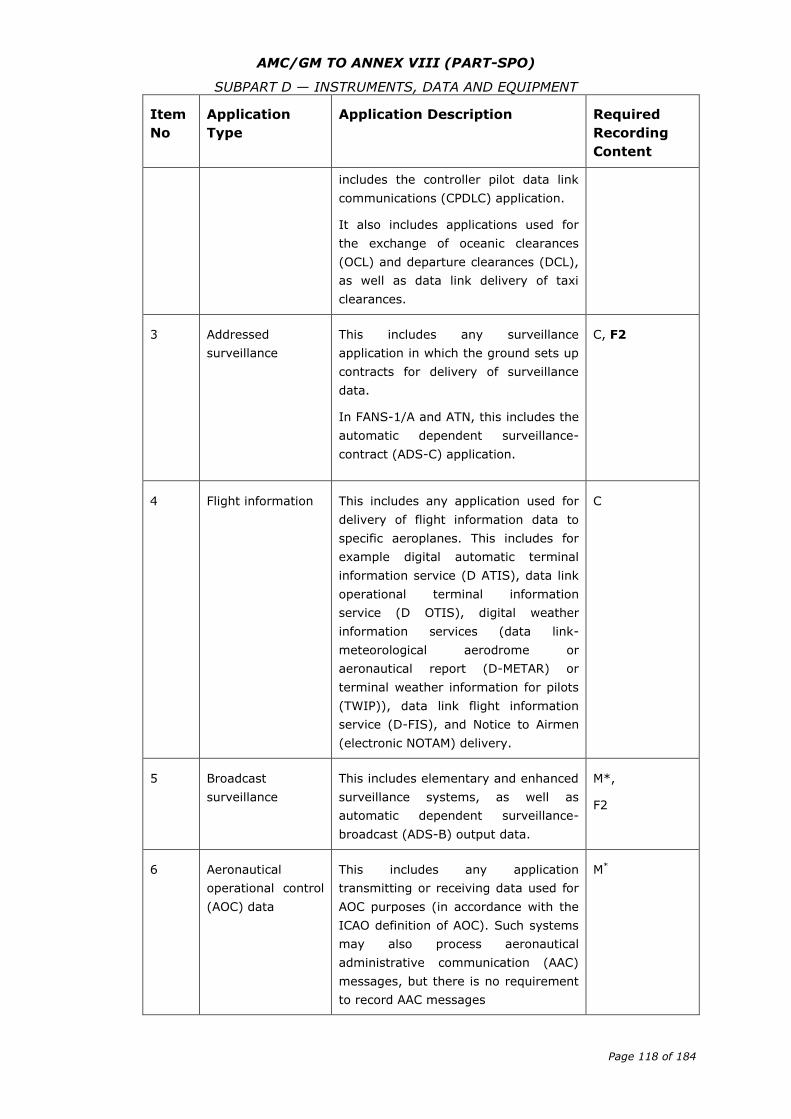
AMC/GM TO ANNEX VIII (PART-SPO)
SUBPART D — INSTRUMENTS, DATA AND EQUIPMENT
Page 118 of 184
Item
No
Application
Type
Application Description Required
Recording
Content
includes the controller pilot data link
communications (CPDLC) application.
It also includes applications used for
the exchange of oceanic clearances
(OCL) and departure clearances (DCL),
as well as data link delivery of taxi
clearances.
3 Addressed
surveillance
This includes any surveillance
application in which the ground sets up
contracts for delivery of surveillance
data.
In FANS-1/A and ATN, this includes the
automatic dependent surveillance-
contract (ADS-C) application.
C, F2
4 Flight information This includes any application used for
delivery of flight information data to
specific aeroplanes. This includes for
example digital automatic terminal
information service (D ATIS), data link
operational terminal information
service (D OTIS), digital weather
information services (data link-
meteorological aerodrome or
aeronautical report (D-METAR) or
terminal weather information for pilots
(TWIP)), data link flight information
service (D-FIS), and Notice to Airmen
(electronic NOTAM) delivery.
C
5 Broadcast
surveillance
This includes elementary and enhanced
surveillance systems, as well as
automatic dependent surveillance-
broadcast (ADS-B) output data.
M*,
F2
6 Aeronautical
operational control
(AOC) data
This includes any application
transmitting or receiving data used for
AOC purposes (in accordance with the
ICAO definition of AOC). Such systems
may also process aeronautical
administrative communication (AAC)
messages, but there is no requirement
to record AAC messages
M*
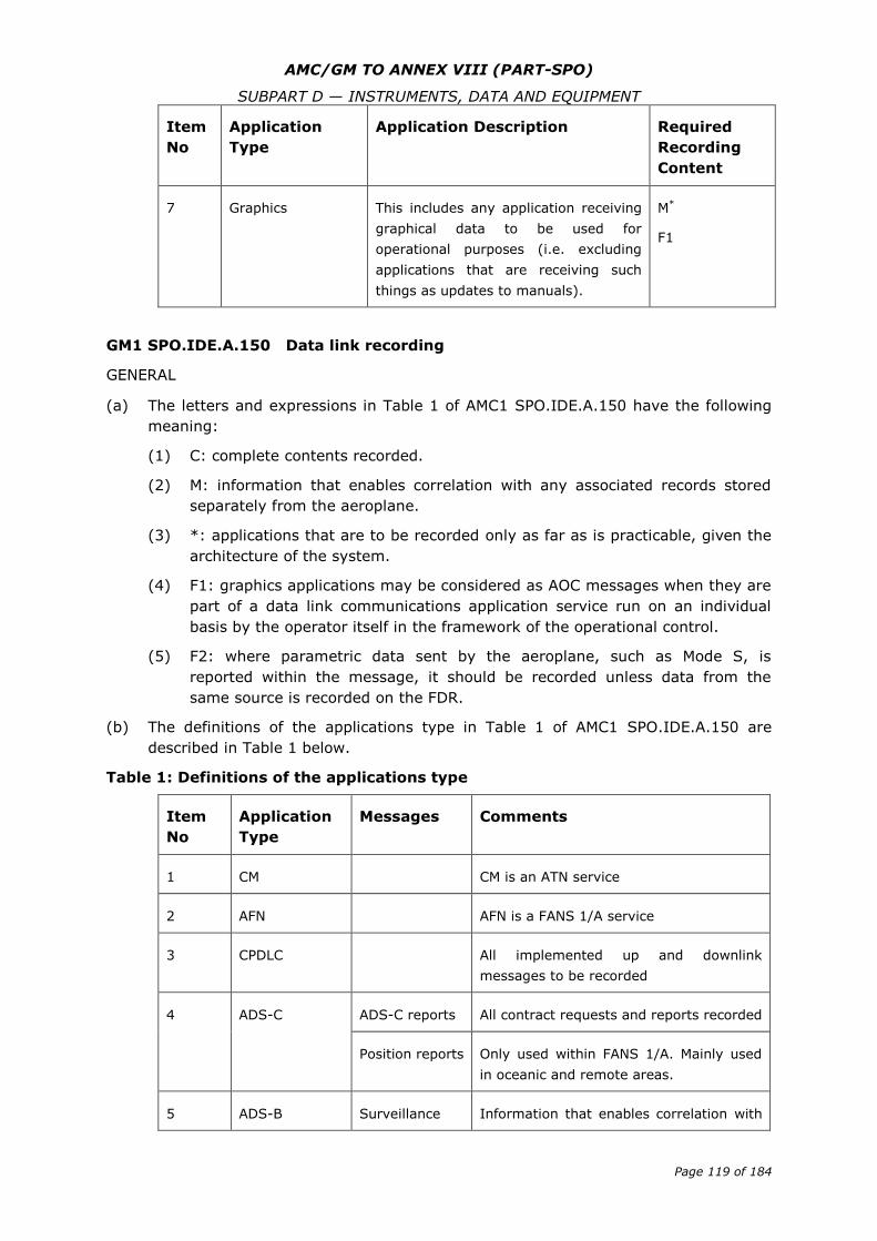
AMC/GM TO ANNEX VIII (PART-SPO)
SUBPART D — INSTRUMENTS, DATA AND EQUIPMENT
Page 119 of 184
Item
No
Application
Type
Application Description Required
Recording
Content
7 Graphics This includes any application receiving
graphical data to be used for
operational purposes (i.e. excluding
applications that are receiving such
things as updates to manuals).
M*
F1
GM1 SPO.IDE.A.150 Data link recording
GENERAL
(a) The letters and expressions in Table 1 of AMC1 SPO.IDE.A.150 have the following
meaning:
(1) C: complete contents recorded.
(2) M: information that enables correlation with any associated records stored
separately from the aeroplane.
(3) *: applications that are to be recorded only as far as is practicable, given the
architecture of the system.
(4) F1: graphics applications may be considered as AOC messages when they are
part of a data link communications application service run on an individual
basis by the operator itself in the framework of the operational control.
(5) F2: where parametric data sent by the aeroplane, such as Mode S, is
reported within the message, it should be recorded unless data from the
same source is recorded on the FDR.
(b) The definitions of the applications type in Table 1 of AMC1 SPO.IDE.A.150 are
described in Table 1 below.
Table 1: Definitions of the applications type
Item
No
Application
Type
Messages Comments
1 CM CM is an ATN service
2 AFN AFN is a FANS 1/A service
3 CPDLC All implemented up and downlink
messages to be recorded
4 ADS-C ADS-C reports All contract requests and reports recorded
Position reports Only used within FANS 1/A. Mainly used
in oceanic and remote areas.
5 ADS-B Surveillance Information that enables correlation with
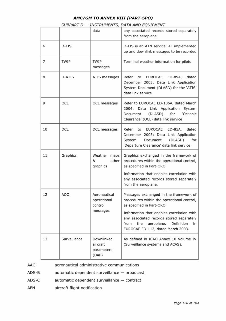
AMC/GM TO ANNEX VIII (PART-SPO)
SUBPART D — INSTRUMENTS, DATA AND EQUIPMENT
Page 120 of 184
data any associated records stored separately
from the aeroplane.
6 D-FIS D-FIS is an ATN service. All implemented
up and downlink messages to be recorded
7 TWIP TWIP
messages
Terminal weather information for pilots
8 D-ATIS ATIS messages Refer to EUROCAE ED-89A, dated
December 2003: Data Link Application
System Document (DLASD) for the ‘ATIS’
data link service
9 OCL OCL messages Refer to EUROCAE ED-106A, dated March
2004: Data Link Application System
Document (DLASD) for ‘Oceanic
Clearance’ (OCL) data link service
10 DCL DCL messages Refer to EUROCAE ED-85A, dated
December 2005: Data Link Application
System Document (DLASD) for
‘Departure Clearance’ data link service
11 Graphics Weather maps
& other
graphics
Graphics exchanged in the framework of
procedures within the operational control,
as specified in Part-ORO.
Information that enables correlation with
any associated records stored separately
from the aeroplane.
12 AOC Aeronautical
operational
control
messages
Messages exchanged in the framework of
procedures within the operational control,
as specified in Part-ORO.
Information that enables correlation with
any associated records stored separately
from the aeroplane. Definition in
EUROCAE ED-112, dated March 2003.
13 Surveillance Downlinked
aircraft
parameters
(DAP)
As defined in ICAO Annex 10 Volume IV
(Surveillance systems and ACAS).
AAC aeronautical administrative communications
ADS-B automatic dependent surveillance — broadcast
ADS-C automatic dependent surveillance — contract
AFN aircraft flight notification
AMC/GM TO ANNEX VIII (PART-SPO)
SUBPART D — INSTRUMENTS, DATA AND EQUIPMENT
Page 121 of 184
AOC aeronautical operational control
ATIS automatic terminal information service
ATSC air traffic service communication
CAP controller access parameters
CPDLC controller pilot data link communications
CM configuration/context management
D-ATIS digital ATIS
D-FIS data link flight information service
D-METAR data link meteorological airport report
DCL departure clearance
FANS Future Air Navigation System
FLIPCY flight plan consistency
OCL oceanic clearance
SAP system access parameters
TWIP terminal weather information for pilots
AMC1 SPO.IDE.A.155 Flight data and cockpit voice combination recorder
GENERAL
When two flight data and cockpit voice combination recorders are installed, one should
be located near the flight crew compartment in order to minimise the risk of data loss
due to a failure of the wiring that gathers data to the recorder. The other should be
located at the rear section of the aeroplane, in order to minimise the risk of data loss
due to recorder damage in the case of a crash.
GM1 SPO.IDE.A.155 Flight data and cockpit voice combination recorder
GENERAL
(a) A flight data and cockpit voice combination recorder is a flight recorder that
records:
(1) all voice communications and the aural environment required by
SPO.IDE.A.140; and
(2) all parameters and specifications required by SPO.IDE.A.145,
with the same specifications required by SPO.IDE.A.140 and SPO.IDE.A.145.
(b) In addition a flight data and cockpit voice combination recorder may record data
link communication messages and related information required by SPO.IDE.A.150.
AMC/GM TO ANNEX VIII (PART-SPO)
SUBPART D — INSTRUMENTS, DATA AND EQUIPMENT
Page 122 of 184
AMC1 SPO.IDE.A.160 Seats, seat safety belts and restraint systems
UPPER TORSO RESTRAINT SYSTEM
The following systems are deemed to be compliant with the requirement for an upper
torso restraint system:
(a) For other-than-complex aeroplanes, a seat belt with a diagonal shoulder strap;
(b) For all aeroplanes, a restraint system having a seat belt and two shoulder straps
that may be used independently; and
(c) For all aeroplanes, a restraint system having a seat belt, two shoulder straps and
additional straps that may be used independently.
SEAT BELT
A seat belt with a diagonal shoulder strap (three anchorage points) is deemed to be
compliant with the requirement for a seat belt (two anchorage points).
AMC1 SPO.IDE.A.165 First-aid kit
CONTENT OF FIRST-AID KITS — OTHER-THAN-COMPLEX MOTOR-POWERED
AEROPLANES
(a) First-aid kits (FAKs) should be equipped with appropriate and sufficient medications
and instrumentation. However, these kits should be amended by the operator
according to the characteristics of the operation (scope of operation, flight
duration, number and demographics of passengers, etc.).
(b) The following should be included in the FAKs:
(1) bandages (assorted sizes),
(2) burns dressings (large and small),
(3) wound dressings (large and small),
(4) adhesive dressings (assorted sizes),
(5) antiseptic wound cleaner,
(6) safety scissors, and
(7) disposable gloves.
AMC2 SPO.IDE.A.165 First-aid kit
CONTENT OF FIRST-AID KITS — COMPLEX MOTOR-POWERED AEROPLANES
(a) First-aid kits should be equipped with appropriate and sufficient medications and
instrumentation. However, these kits should be amended by the operator according
to the characteristics of the operation (scope of operation, flight duration, number
and demographics of persons on board etc.).
(b) The following should be included in the FAKs:
(1) Equipment:
(i) bandages (assorted sizes);
(ii) burns dressings (unspecified);
(iii) wound dressings (large and small);
AMC/GM TO ANNEX VIII (PART-SPO)
SUBPART D — INSTRUMENTS, DATA AND EQUIPMENT
Page 123 of 184
(iv) adhesive dressings (assorted sizes);
(v) adhesive tape;
(vi) adhesive wound closures;
(vii) safety pins;
(viii) safety scissors;
(ix) antiseptic wound cleaner;
(x) disposable resuscitation aid;
(xi) disposable gloves;
(xii) tweezers: splinter; and
(xiii) thermometers (non-mercury).
(2) Medications:
(i) simple analgesic (may include liquid form);
(ii) antiemetic;
(iii) nasal decongestant;
(iv) gastrointestinal antacid, in the case of aeroplanes carrying more than
nine persons;
(v) anti-diarrhoeal medication, in the case of aeroplanes carrying more than
nine persons; and
(vi) antihistamine.
(3) Other:
(i) a list of contents in at least two languages (English and one other). This
should include information on the effects and side effects of medications
carried;
(ii) first-aid handbook, current edition;
(iii) medical incident report form; and
(iv) biohazard disposal bags.
(4) An eye irrigator, although not required to be carried in the FAK, should,
where possible, be available for use on the ground.
AMC3 SPO.IDE.A.165 First-aid kit
MAINTENANCE OF FIRST-AID KIT
To be kept up to date, the first-aid kit should be:
(a) inspected periodically to confirm, to the extent possible, that contents are
maintained in the condition necessary for their intended use;
(b) replenished at regular intervals, in accordance with instructions contained on their
labels, or as circumstances warrant; and
(c) replenished after use in-flight at the first opportunity where replacement items are
available.
AMC/GM TO ANNEX VIII (PART-SPO)
SUBPART D — INSTRUMENTS, DATA AND EQUIPMENT
Page 124 of 184
AMC1 SPO.IDE.A.170 Supplemental oxygen — pressurised aeroplanes
DETERMINATION OF OXYGEN
(a) In the determination of oxygen for the routes to be flown, it is assumed that the
aeroplane will descend in accordance with the emergency procedures specified in
the AFM, without exceeding its operating limitations, to a flight altitude that will
allow the flight to be completed safely (i.e. flight altitudes ensuring adequate
terrain clearance, navigational accuracy, hazardous weather avoidance, etc.).
(b) The amount of oxygen should be determined on the basis of cabin pressure
altitude, flight duration and on the assumption that a cabin pressurisation failure
will occur at the pressure altitude or point of flight that is most critical from the
standpoint of oxygen need.
(c) Following a cabin pressurisation failure, the cabin pressure altitude should be
considered to be the same as the aeroplane pressure altitude unless it can be
demonstrated to the competent authority that no probable failure of the cabin or
pressurisation system will result in a cabin pressure altitude equal to the aeroplane
pressure altitude. Under these circumstances, the demonstrated maximum cabin
pressure altitude may be used as a basis for determination of oxygen supply.
GM1 SPO.IDE.A.170(c)(2) Supplemental oxygen — pressurised aeroplanes
QUICK DONNING MASKS
A quick donning mask is a type of mask that:
(a) can be placed on the face from its ready position, properly secured, sealed and
supplying oxygen upon demand, with one hand and within 5 seconds and will
thereafter remain in position, both hands being free;
(b) can be donned without disturbing eye glasses and without delaying the flight crew
member from proceeding with assigned emergency duties;
(c) once donned, does not prevent immediate communication between the flight crew
members and other crew members over the aircraft intercommunication system;
and
(d) does not inhibit radio communications.
AMC1 SPO.IDE.A.175 Supplemental oxygen — non-pressurised aeroplanes
DETERMINATION OF OXYGEN
(a) In the determination of oxygen for the routes to be flown, it is assumed that the
aeroplane will descend in accordance with the emergency procedures specified in
the AFM, without exceeding its operating limitations, to a flight altitude that will
allow the flight to be completed safely (i.e. flight altitudes ensuring adequate
terrain clearance, navigational accuracy, hazardous weather avoidance etc.).
(b) The amount of oxygen should be determined on the basis of cabin pressure altitude
and flight duration.
AMC/GM TO ANNEX VIII (PART-SPO)
SUBPART D — INSTRUMENTS, DATA AND EQUIPMENT
Page 125 of 184
AMC1 SPO.IDE.A.180 Hand fire extinguishers
NUMBER, LOCATION AND TYPE
(a) The number and location of hand fire extinguishers should be such as to provide
adequate availability for use, account being taken of the number and size of the
cabin compartments, the need to minimise the hazard of toxic gas concentrations
and the location of toilets, galleys, etc. These considerations may result in the
number of fire extinguishers being greater than the minimum required.
(b) There should be at least one hand fire extinguisher installed in the flight crew
compartment and this should be suitable for fighting both flammable fluid and
electrical equipment fires. Additional hand fire extinguishers may be required for
the protection of other compartments accessible to the flight crew or task specialist
in flight. Dry chemical fire extinguishers should not be used in the flight crew
compartment, or in any compartment not separated by a partition from the flight
crew compartment, because of the adverse effect on vision during discharge and, if
conductive, interference with electrical contacts by the chemical residues.
(c) Where only one hand fire extinguisher is required in the cabin compartments, it
should be located near the task specialist’s station, where provided.
(d) Where two or more hand fire extinguishers are required in the cabin compartments
and their location is not otherwise dictated by consideration of (a), an extinguisher
should be located near each end of the cabin with the remainder distributed
throughout the cabin as evenly as is practicable.
(e) Unless an extinguisher is clearly visible, its location should be indicated by a
placard or sign. Appropriate symbols may also be used to supplement such a
placard or sign.
AMC1 SPO.IDE.A.185 Marking of break-in points
COLOUR AND CORNERS’ MARKING
(a) The colour of the markings should be red or yellow and, if necessary, should be
outlined in white to contrast with the background.
(b) If the corner markings are more than 2 m apart, intermediate lines 9 cm x 3 cm
should be inserted so that there is no more than 2 m between adjacent markings.
AMC1 SPO.IDE.A.190 Emergency locator transmitter (ELT)
BATTERIES
(a) All batteries used in ELTs or PLBs should be replaced (or recharged, if the battery is
rechargeable) when the equipment has been in use for more than 1 cumulative
hour or in the following cases:
(1) Batteries specifically designed for use in ELTs and having an airworthiness
release certificate (EASA Form 1 or equivalent) should be replaced (or
recharged, if the battery is rechargeable) before the end of their useful life in
accordance with the maintenance instructions applicable to the ELT.
(2) Standard batteries manufactured in accordance with an industry standard and
not having an airworthiness release certificate (EASA Form 1 or equivalent),
AMC/GM TO ANNEX VIII (PART-SPO)
SUBPART D — INSTRUMENTS, DATA AND EQUIPMENT
Page 126 of 184
when used in ELTs should be replaced (or recharged, if the battery is
rechargeable) when 50 % of their useful life (or for rechargeable, 50 % of
their useful life of charge), as established by the battery manufacturer, has
expired.
(3) All batteries used in PLBs should be replaced (or recharged, if the battery is
rechargeable) when 50 % of their useful life (or for rechargeable, 50 % of
their useful life of charge), as established by the battery manufacturer, has
expired.
(4) The battery useful life (or useful life of charge) criteria in (1),(2) and (3) do
not apply to batteries (such as water-activated batteries) that are essentially
unaffected during probable storage intervals.
(b) The new expiry date for a replaced (or recharged) battery should be legibly marked
on the outside of the equipment.
AMC2 SPO.IDE.A.190 Emergency locator transmitter (ELT)
TYPES OF ELT AND GENERAL TECHNICAL SPECIFICATIONS
(a) The ELT required by this provision should be one of the following:
(1) Automatic fixed (ELT(AF)). An automatically activated ELT that is
permanently attached to an aircraft and is designed to aid search and rescue
(SAR) teams in locating the crash site.
(2) Automatic portable (ELT(AP)). An automatically activated ELT that is rigidly
attached to an aircraft before a crash, but is readily removable from the
aircraft after a crash. It functions as an ELT during the crash sequence. If the
ELT does not employ an integral antenna, the aircraft-mounted antenna may
be disconnected and an auxiliary antenna (stored on the ELT case) attached
to the ELT. The ELT can be tethered to a survivor or a life-raft. This type of
ELT is intended to aid SAR teams in locating the crash site or survivor(s).
(3) Automatic deployable (ELT(AD)). An ELT that is rigidly attached to the aircraft
before the crash and that is automatically ejected, deployed and activated by
an impact, and, in some cases, also by hydrostatic sensors. Manual
deployment is also provided. This type of ELT should float in water and is
intended to aid SAR teams in locating the crash site.
(4) Survival ELT (ELT(S)). An ELT that is removable from an aircraft, stowed so
as to facilitate its ready use in an emergency and manually activated by a
survivor. An ELT(S) may be activated manually or automatically (e.g. by
water activation). It should be designed to be tethered to a life-raft or a
survivor.
(b) To minimise the possibility of damage in the event of crash impact, the automatic
ELT should be rigidly fixed to the aircraft structure, as far aft as is practicable, with
its antenna and connections arranged so as to maximise the probability of the
signal being transmitted after a crash.
(c) Any ELT carried should operate in accordance with the relevant provisions of ICAO
Annex 10, Volume III and should be registered with the national agency
responsible for initiating search and rescue or other nominated agency.
AMC/GM TO ANNEX VIII (PART-SPO)
SUBPART D — INSTRUMENTS, DATA AND EQUIPMENT
Page 127 of 184
AMC3 SPO.IDE.A.190 Emergency locator transmitter (ELT)
PLB TECHNICAL SPECIFICATIONS
(a) A personal locator beacon (PLB) should have a built-in GNSS receiver with a
cosmicheskaya sistyema poiska avariynich sudov — search and rescue satellite-
aided tracking (COSPAS-SARSAT) type approval number. However, devices with a
COSPAS-SARSAT with a number belonging to series 700 are excluded as this series
of numbers identifies the special-use beacons not meeting all the technical
requirements and all the tests specified by COSPAS-SARSAT.
(b) Any PLB carried should be registered with the national agency responsible for
initiating search and rescue or other nominated agency.AMC4 SPO.IDE.A.190
Emergency locator transmitter (ELT)
BRIEFING ON PLB USE
When a PLB is carried by a task specialist, he/she should be briefed on its characteristics
and use by the pilot-in-command before the flight.
GM1 SPO.IDE.A.190 Emergency locator transmitter (ELT)
TERMINOLOGY
(a) An ELT is a generic term describing equipment that broadcasts distinctive signals
on designated frequencies and, depending on application, may be activated by
impact or may be manually activated.
(b) A PLB is an emergency beacon other than an ELT that broadcasts distinctive signals
on designated frequencies, is standalone, portable and is manually activated by the
survivors.
GM2 SPO.IDE.A.190 Emergency locator transmitter (ELT)
MAXIMUM CERTIFIED SEATING CONFIGURATION
The maximum certified seating configuration does not include flight crew seats.
AMC1 SPO.IDE.A.195 Flight over water
ACCESSIBILITY OF LIFE-JACKETS
The life-jacket, if not worn, should be accessible from the seat or station of the person
for whose use it is provided, with a safety belt or a restraint system fastened.
MEANS OF ILLUMINATION FOR LIFE-JACKETS
The means of electric illumination should be a survivor locator light as defined in the
applicable ETSO issued by the Agency or equivalent.
RISK ASSESSMENT
(a) When conducting the risk assessment, the pilot-in-command should base his/her
decision, as far as is practicable, on the Implementing Rules and AMCs applicable
to the operation of the aeroplane.
(b) The pilot-in-command should, for determining the risk, take the following operating
environment and conditions into account:
AMC/GM TO ANNEX VIII (PART-SPO)
SUBPART D — INSTRUMENTS, DATA AND EQUIPMENT
Page 128 of 184
(1) sea state;
(2) sea and air temperatures;
(3) the distance from land suitable for making an emergency landing; and
(4) the availability of search and rescue facilities.
AMC2 SPO.IDE.A.195 Flight over water
LIFE RAFTS AND EQUIPMENT FOR MAKING DISTRESS SIGNALS
(a) The following should be readily available with each life-raft:
(1) means for maintaining buoyancy;
(2) a sea anchor;
(3) life-lines and means of attaching one life-raft to another;
(4) paddles for life-rafts with a capacity of six or less;
(5) means of protecting the occupants from the elements;
(6) a water-resistant torch;
(7) signalling equipment to make the pyrotechnic distress signals described in
ICAO Annex 2, Rules of the Air;
(8) 100 g of glucose tablets for each four, or fraction of four, persons that the
life-raft is designed to carry:
(9) at least 2 litres of drinkable water provided in durable containers or means of
making sea water drinkable or a combination of both; and
(10) first-aid equipment.
(b) As far as practicable, items listed in (a) should be contained in a pack.
GM1 SPO.IDE.A.195 Flight over water
SEAT CUSHIONS
Seat cushions are not considered to be flotation devices.
AMC1 SPO.IDE.A.200 Survival equipment
ADDITIONAL SURVIVAL EQUIPMENT
(a) The following additional survival equipment should be carried when required:
(1) 500 ml of water for each four, or fraction of four, persons on board;
(2) one knife;
(3) first-aid equipment; and
(4) one set of air/ground codes.
(b) In addition, when polar conditions are expected, the following should be carried:
(1) a means of melting snow;
(2) one snow shovel and one ice saw;
AMC/GM TO ANNEX VIII (PART-SPO)
SUBPART D — INSTRUMENTS, DATA AND EQUIPMENT
Page 129 of 184
(3) sleeping bags for use by 1/3 of all persons on board and space blankets for
the remainder or space blankets for all persons on board; and
(4) one arctic/polar suit for each crew member
(c) If any item of equipment contained in the above list is already carried on board the
aircraft in accordance with another requirement, there is no need for this to be
duplicated.
AMC1 SPO.IDE.A.200(a)(2) Survival equipment
SURVIVAL ELT
An ELT(AP) may be used to replace one required ELT(S) provided that it meets the
ELT(S) requirements. A water-activated ELT(S) is not an ELT(AP).
AMC1 SPO.IDE.A.200(b)(2) Survival equipment
APPLICABLE AIRWORTHINESS STANDARD
The applicable airworthiness standard should be CS-25 or equivalent.
GM1 SPO.IDE.A.200 Survival equipment
SIGNALLING EQUIPMENT
The signalling equipment for making distress signals is described in ICAO Annex 2, Rules
of the Air.
GM2 SPO.IDE.A.200 Survival equipment
AREAS IN WHICH SEARCH AND RESCUE WOULD BE ESPECIALLY DIFFICULT
The expression ‘areas in which search and rescue would be especially difficult’ should be
interpreted, in this context, as meaning:
(a) areas so designated by the authority responsible for managing search and rescue;
or
(b) areas that are largely uninhabited and where:
(1) the authority referred to in (a) not published any information to confirm
whether search and rescue would be or would not be especially difficult; and
(2) the authority referred to in (a) does not, as a matter of policy, designate
areas as being especially difficult for search and rescue.
GM1 SPO.IDE.A.205 Individual protective equipment
TYPES OF INDIVIDUAL PROTECTIVE EQUIPMENT
Personal protective equipment should include, but is not limited to: flying suits, gloves,
helmets, protective shoes, etc.
AMC/GM TO ANNEX VIII (PART-SPO)
SUBPART D — INSTRUMENTS, DATA AND EQUIPMENT
Page 130 of 184
AMC1 SPO.IDE.A.210 Headset
GENERAL
(a) A headset consists of a communication device that includes two earphones to
receive and a microphone to transmit audio signals to the aeroplane’s
communication system. To comply with the minimum performance requirements,
the earphones and microphone should match the communication system’s
characteristics and the flight crew compartment environment. The headset should
be adequately adjustable in order to fit the flight crew’s head. Headset boom
microphones should be of the noise cancelling type.
(b) If the intention is to utilise noise cancelling earphones, the operator should ensure
that the earphones do not attenuate any aural warnings or sounds necessary for
alerting the flight crew on matters related to the safe operation of the aeroplane.
GM1 SPO.IDE.A.210 Headset
GENERAL
The term ‘headset’ includes any aviation helmet incorporating headphones and
microphone worn by a flight crew member.
GM1 SPO.IDE.A.215 Radio communication equipment
APPLICABLE AIRSPACE REQUIREMENTS
For aeroplanes being operated under European air traffic control, the applicable airspace
requirements include the Single European Sky legislation.
AMC1 SPO.IDE.A.220 Navigation equipment
NAVIGATION WITH VISUAL REFERENCE TO LANDMARKS — OTHER-THAN-COMPLEX
AEROPLANES
Where other-than-complex aeroplanes, with the surface in sight, can proceed according
to the ATS flight plan by navigation with visual reference to landmarks, no additional
equipment is needed to comply with SPO.IDE.A.220 (a)(1).
AMC1 SPO.IDE.A.225 Transponder
GENERAL
(a) The secondary surveillance radar (SSR) transponders of aeroplanes being operated
under European air traffic control should comply with any applicable Single
European Sky legislation.
(b) If the Single European Sky legislation is not applicable, the SSR transponders
should operate in accordance with the relevant provisions of Volume IV of ICAO
Annex 10.
AMC/GM TO ANNEX VIII (PART-SPO)
SUBPART D — INSTRUMENTS, DATA AND EQUIPMENT
Page 131 of 184
Section 2 — Helicopters
GM1 SPO.IDE.H.100(a) Instruments and equipment — general
APPLICABLE AIRWORTHINESS REQUIREMENTS
The applicable airworthiness requirements for approval of instruments and equipment
required by this Part are the following:
(a) Commission Regulation (EU) No 748/2012 for helicopters registered in the EU; and
(b) Airworthiness requirements of the state of registry for helicopters registered
outside the EU.
GM1 SPO.IDE.H.100(b) Instruments and equipment — general
REQUIRED INSTRUMENTS AND EQUIPMENT THAT DO NOT NEED TO BE APPROVED IN
ACCORDANCE WITH THE APPLICABLE AIRWORTHINESS REQUIREMENTS
The functionality of non-installed instruments and equipment required by this Subpart
and that do not need an equipment approval, as listed in SPO.IDE.H.100(b), should be
checked against recognised industry standards appropriate to the intended purpose. The
operator is responsible for ensuring the maintenance of these instruments and
equipment.
GM1 SPO.IDE.H.100(c) Instruments and equipment — general
NOT REQUIRED INSTRUMENTS AND EQUIPMENT THAT DO NOT NEED TO BE APPROVED
IN ACCORDANCE WITH THE APPLICABLE AIRWORTHINESS REQUIREMENTS, BUT ARE
CARRIED ON A FLIGHT
(a) The provision of this paragraph does not exempt any installed instrument or item
of equipment from complying with the applicable airworthiness requirements. In
this case, the installation should be approved as required in the applicable
airworthiness requirements and should comply with the applicable airworthiness
codes.
(b) The failure of additional non-installed instruments or equipment not required by
this Part or by the applicable airworthiness requirements or any applicable airspace
requirements should not adversely affect the airworthiness and/or the safe
operation of the helicopter. Examples may be the following:
(1) portable electronic flight bag (EFB);
(2) portable electronic devices carried by crew members or task specialists; and
(3) non-installed task specialists equipment.
GM1 SPO.IDE.H.100 (d) Instruments and equipment — general
POSITIONING OF INSTRUMENTS
This requirement implies that whenever a single instrument is required in a helicopter
operated in a multi-crew environment, the instrument needs to be visible from each
flight crew station.
AMC/GM TO ANNEX VIII (PART-SPO)
SUBPART D — INSTRUMENTS, DATA AND EQUIPMENT
Page 132 of 184
AMC1 SPO.IDE.H.115 Operating lights
LANDING LIGHT
The landing light should be trainable, at least in the vertical plane, or optionally be an
additional fixed light or lights positioned to give a wide spread of illumination.
AMC1 SPO.IDE.H.120 & SPO.IDE.H.125 Operations under VFR & operations
under IFR — flight and navigational instruments and associated equipment
INTEGRATED INSTRUMENTS
(a) Individual equipment requirements may be met by combinations of instruments, by
integrated flight systems or by a combination of parameters on electronic displays.
The information so available to each required pilot should not be less than that
required in the applicable operational requirements, and the equivalent safety of
the installation should be approved during type certification of the helicopter for
the intended type of operation.
(b) The means of measuring and indicating turn and slip, helicopter attitude and
stabilised helicopter heading may be met by combinations of instruments or by
integrated flight director systems, provided that the safeguards against total
failure, inherent in the three separate instruments, are retained.
AMC1 SPO.IDE.H.120(a)(1) & SPO.IDE.H.125(a)(1) Operations under VFR &
operations under IFR — flight and navigational instruments and associated
equipment
MEANS OF MEASURING AND DISPLAYING MAGNETIC HEADING
The means of measuring and displaying magnetic direction should be a magnetic
compass or equivalent.
AMC1 SPO.IDE.H.120(a)(2) & SPO.IDE.H.125(a)(2) Operations under VFR &
operations under IFR — flight and navigational instruments and associated
equipment
MEANS OF MEASURING AND DISPLAYING THE TIME — COMPLEX MOTOR-POWERED
AIRCRAFT
An acceptable means of compliance is a clock displaying hours, minutes and seconds,
with a sweep-second pointer or digital presentation.
MEANS OF MEASURING AND DISPLAYING THE TIME — OTHER-THAN- COMPLEX MOTOR-
POWERED AIRCRAFT
An acceptable means of measuring and displaying the time in hours, minutes and
seconds may be a wrist watch capable of the same functions.
AMC/GM TO ANNEX VIII (PART-SPO)
SUBPART D — INSTRUMENTS, DATA AND EQUIPMENT
Page 133 of 184
AMC1 SPO.IDE.H.120(a)(3) & SPO.IDE.H.125(a)(3) Operations under VFR &
operations under IFR — flight and navigational instruments and associated
equipment
CALIBRATION OF THE MEANS OF MEASURING AND DISPLAYING PRESSURE ALTITUDE
The instrument measuring and displaying pressure altitude should be of a sensitive type
calibrated in feet (ft), with a sub-scale setting, calibrated in hectopascals/millibars,
adjustable for any barometric pressure likely to be set during flight.
GM1 SPO.IDE.H.125(a)(3) Operations under IFR — flight and navigational
instruments and associated equipment
ALTIMETERS
Altimeters with counter drum-pointer or equivalent presentation are considered to be
less susceptible to misinterpretation for helicopters operating above 10 000 ft.
AMC1 SPO.IDE.H.120(a)(4) & SPO.IDE.H.125(a)(4) Operations under VFR &
operations under IFR — flight and navigational instruments and associated
equipment
CALIBRATION OF THE INSTRUMENT INDICATING AIRSPEED
(a) The instrument indicating airspeed should be calibrated in knots (kt).
(b) In the case of helicopters with an MCTOM below 2 000 kg, calibration in kilometres
(km) per hour or in miles per hour (mph) is acceptable when such units are used in
the AFM.
AMC1 SPO.IDE.H.120(a)(5) Operations under VFR — flight and navigational
instruments and associated equipment
SLIP
For other-than-complex helicopters the means of measuring and displaying slip may be a
slip string for operations under VFR.
AMC1 SPO.IDE.H.125(a)(9) Operations under IFR — flight and navigational
instruments and associated equipment
MEANS OF DISPLAYING OUTSIDE AIR TEMPERATURE
(a) The means of displaying outside air temperature should be calibrated in degrees
Celsius.
(b) In the case of helicopters with a maximum certified take-off mass (MCTOM) below
2 000 kg, calibration in degrees Fahrenheit is acceptable, when such unit is used in
the AFM.
(c) The means of displaying outside air temperature may be an air temperature
indicator that provides indications that are convertible to outside air temperature.
AMC/GM TO ANNEX VIII (PART-SPO)
SUBPART D — INSTRUMENTS, DATA AND EQUIPMENT
Page 134 of 184
AMC1 SPO.IDE.H.120(d) & SPO.IDE.H.125(c) Operations under VFR &
operations under IFR — flight and navigational instruments and associated
equipment
MULTI-PILOT OPERATIONS — DUPLICATE INSTRUMENTS
Duplicate instruments include separate displays for each pilot and separate selectors or
other associated equipment where appropriate.
AMC1 SPO.IDE.H.120(b)(1)(iii) & SPO.IDE.H.125(a)(8) Operations under VFR
& operations under IFR — flight and navigational instruments and associated
equipment
STABILISED HEADING
Stabilised direction should be achieved for VFR flights by a gyroscopic direction indicator,
whereas for IFR flights, this should be achieved through a magnetic gyroscopic direction
indicator.
AMC1 SPO.IDE.H.120(b)(3) & SPO.IDE.H.125(d) Operations under VFR &
operations under IFR — flight and navigational instruments and associated
equipment
MEANS OF PREVENTING MALFUNCTION DUE TO CONDENSATION OR ICING
The means of preventing malfunction due to either condensation or icing of the airspeed
indicating system should be a heated pitot tube or equivalent.
AMC1 SPO.IDE.H.125(f)(2) Operations under IFR — flight and navigational
instruments and associated equipment
CHART HOLDER
An acceptable means of compliance with the chart holder requirement would be to
display a pre-composed chart on an electronic flight bag (EFB).
AMC1 SPO.IDE.H.132 Airborne weather detecting equipment — complex
motor-powered helicopters
GENERAL
The airborne weather detecting equipment should be an airborne weather radar.
AMC1 SPO.IDE.H.135 Flight crew interphone system
TYPE OF FLIGHT CREW INTERPHONE
The flight crew interphone system should not be of a handheld type.
AMC1 SPO.IDE.H.140 Cockpit voice recorder
GENERAL
The operational performance requirements for CVRs should be those laid down in
EUROCAE Document ED-112 (Minimum Operational Performance Specification for Crash
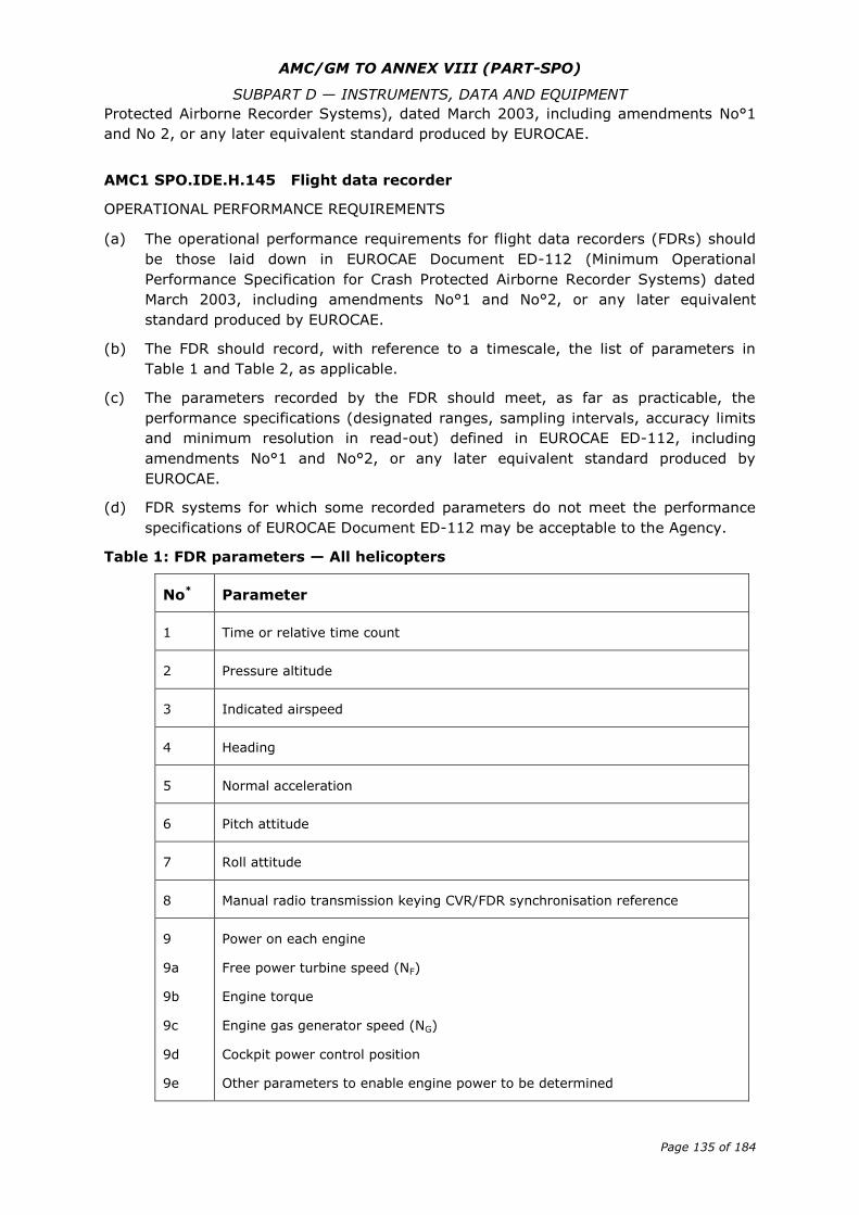
AMC/GM TO ANNEX VIII (PART-SPO)
SUBPART D — INSTRUMENTS, DATA AND EQUIPMENT
Page 135 of 184
Protected Airborne Recorder Systems), dated March 2003, including amendments No°1
and No 2, or any later equivalent standard produced by EUROCAE.
AMC1 SPO.IDE.H.145 Flight data recorder
OPERATIONAL PERFORMANCE REQUIREMENTS
(a) The operational performance requirements for flight data recorders (FDRs) should
be those laid down in EUROCAE Document ED-112 (Minimum Operational
Performance Specification for Crash Protected Airborne Recorder Systems) dated
March 2003, including amendments No°1 and No°2, or any later equivalent
standard produced by EUROCAE.
(b) The FDR should record, with reference to a timescale, the list of parameters in
Table 1 and Table 2, as applicable.
(c) The parameters recorded by the FDR should meet, as far as practicable, the
performance specifications (designated ranges, sampling intervals, accuracy limits
and minimum resolution in read-out) defined in EUROCAE ED-112, including
amendments No°1 and No°2, or any later equivalent standard produced by
EUROCAE.
(d) FDR systems for which some recorded parameters do not meet the performance
specifications of EUROCAE Document ED-112 may be acceptable to the Agency.
Table 1: FDR parameters — All helicopters
No* Parameter
1 Time or relative time count
2 Pressure altitude
3 Indicated airspeed
4 Heading
5 Normal acceleration
6 Pitch attitude
7 Roll attitude
8 Manual radio transmission keying CVR/FDR synchronisation reference
9
9a
9b
9c
9d
9e
Power on each engine
Free power turbine speed (NF)
Engine torque
Engine gas generator speed (NG)
Cockpit power control position
Other parameters to enable engine power to be determined
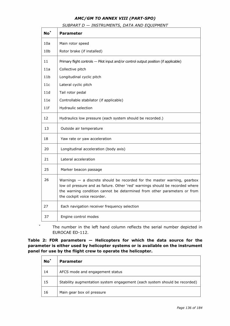
AMC/GM TO ANNEX VIII (PART-SPO)
SUBPART D — INSTRUMENTS, DATA AND EQUIPMENT
Page 136 of 184
No* Parameter
10a
10b
Main rotor speed
Rotor brake (if installed)
11
11a
11b
11c
11d
11e
11f
Primary flight controls — Pilot input and/or control output position (if applicable)
Collective pitch
Longitudinal cyclic pitch
Lateral cyclic pitch
Tail rotor pedal
Controllable stabilator (if applicable)
Hydraulic selection
12 Hydraulics low pressure (each system should be recorded.)
13 Outside air temperature
18 Yaw rate or yaw acceleration
20 Longitudinal acceleration (body axis)
21 Lateral acceleration
25 Marker beacon passage
26 Warnings — a discrete should be recorded for the master warning, gearbox
low oil pressure and as failure. Other ‘red’ warnings should be recorded where
the warning condition cannot be determined from other parameters or from
the cockpit voice recorder.
27 Each navigation receiver frequency selection
37 Engine control modes
* The number in the left hand column reflects the serial number depicted in
EUROCAE ED-112.
Table 2: FDR parameters — Helicopters for which the data source for the
parameter is either used by helicopter systems or is available on the instrument
panel for use by the flight crew to operate the helicopter.
No* Parameter
14 AFCS mode and engagement status
15 Stability augmentation system engagement (each system should be recorded)
16 Main gear box oil pressure
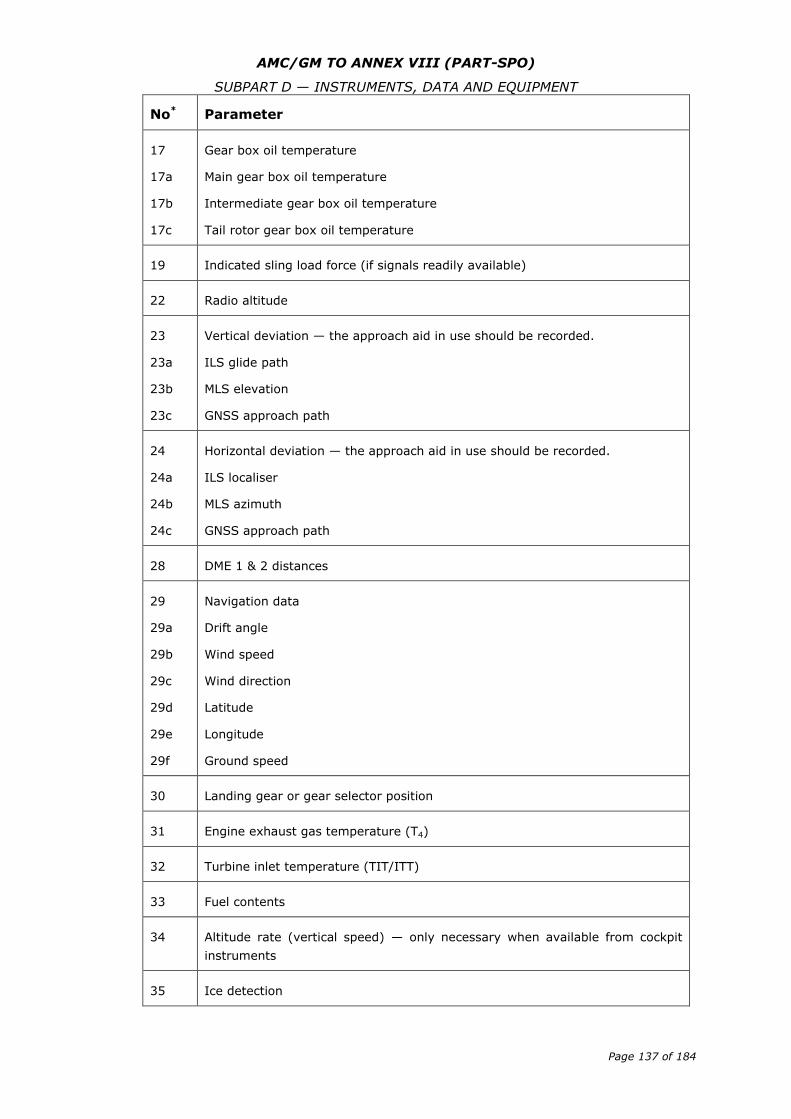
AMC/GM TO ANNEX VIII (PART-SPO)
SUBPART D — INSTRUMENTS, DATA AND EQUIPMENT
Page 137 of 184
No* Parameter
17
17a
17b
17c
Gear box oil temperature
Main gear box oil temperature
Intermediate gear box oil temperature
Tail rotor gear box oil temperature
19 Indicated sling load force (if signals readily available)
22 Radio altitude
23
23a
23b
23c
Vertical deviation — the approach aid in use should be recorded.
ILS glide path
MLS elevation
GNSS approach path
24
24a
24b
24c
Horizontal deviation — the approach aid in use should be recorded.
ILS localiser
MLS azimuth
GNSS approach path
28 DME 1 & 2 distances
29
29a
29b
29c
29d
29e
29f
Navigation data
Drift angle
Wind speed
Wind direction
Latitude
Longitude
Ground speed
30 Landing gear or gear selector position
31 Engine exhaust gas temperature (T4)
32 Turbine inlet temperature (TIT/ITT)
33 Fuel contents
34 Altitude rate (vertical speed) — only necessary when available from cockpit
instruments
35 Ice detection
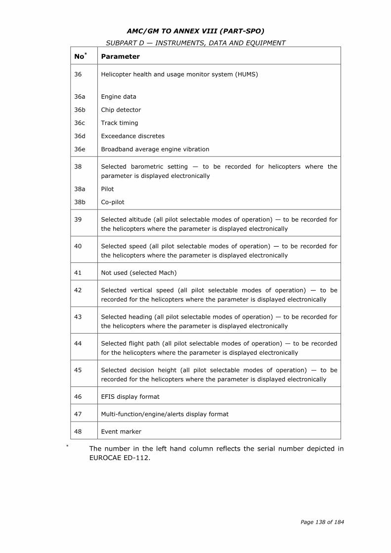
AMC/GM TO ANNEX VIII (PART-SPO)
SUBPART D — INSTRUMENTS, DATA AND EQUIPMENT
Page 138 of 184
No* Parameter
36
36a
36b
36c
36d
36e
Helicopter health and usage monitor system (HUMS)
Engine data
Chip detector
Track timing
Exceedance discretes
Broadband average engine vibration
38
38a
38b
Selected barometric setting — to be recorded for helicopters where the
parameter is displayed electronically
Pilot
Co-pilot
39 Selected altitude (all pilot selectable modes of operation) — to be recorded for
the helicopters where the parameter is displayed electronically
40 Selected speed (all pilot selectable modes of operation) — to be recorded for
the helicopters where the parameter is displayed electronically
41 Not used (selected Mach)
42 Selected vertical speed (all pilot selectable modes of operation) — to be
recorded for the helicopters where the parameter is displayed electronically
43 Selected heading (all pilot selectable modes of operation) — to be recorded for
the helicopters where the parameter is displayed electronically
44 Selected flight path (all pilot selectable modes of operation) — to be recorded
for the helicopters where the parameter is displayed electronically
45 Selected decision height (all pilot selectable modes of operation) — to be
recorded for the helicopters where the parameter is displayed electronically
46 EFIS display format
47 Multi-function/engine/alerts display format
48 Event marker
* The number in the left hand column reflects the serial number depicted in
EUROCAE ED-112.
AMC/GM TO ANNEX VIII (PART-SPO)
SUBPART D — INSTRUMENTS, DATA AND EQUIPMENT
Page 139 of 184
AMC1 SPO.IDE.H.150 Data link recording
GENERAL
(a) As a means of compliance with SPO.IDE.H.150, the recorder on which the data link
messages are recorded should be:
(1) the CVR;
(2) the FDR;
(3) a combination recorder when SPO.IDE.H.155 is applicable; or
(4) a dedicated flight recorder. In such case, the operational performance
requirements for this recorder should be those laid down in EUROCAE
Document ED-112 (Minimum Operational Performance Specification for Crash
Protected Airborne Recorder Systems), dated March 2003, including
amendments No°1 and No°2, or any later equivalent standard produced by
EUROCAE.
(b) As a means of compliance with SPO.IDE.H.150 (a)(2), the operator should enable
correlation by providing information that allows an accident investigator to
understand what data was provided to the aircraft and, when the provider
identification is contained in the message, by which provider.
(c) The timing information associated with the data link communications messages
required to be recorded by SPO.IDE.H.150(a)(3) should be capable of being
determined from the airborne-based recordings. This timing information should
include at least the following:
(1) the time each message was generated;
(2) the time any message was available to be displayed by the flight crew;
(3) the time each message was actually displayed or recalled from a queue; and
(4) the time of each status change.
(d) The message priority should be recorded when it is defined by the protocol of the
data link communication message being recorded.
(e) The expression ‘taking into account the system’s architecture’, in SPO.IDE.H.150
(a)(3), means that the recording of the specified information may be omitted if the
existing source systems involved would require a major upgrade. The following
should be considered:
(1) the extent of the modification required;
(2) the down-time period; and
(3) equipment software development.
(f) Data link communications messages that support the applications in Table 1 should
be recorded.
(g) Further details on the recording requirements can be found in the recording
requirement matrix in Appendix D.2 of EUROCAE Document ED-93 (Minimum
Aviation System Performance Specification for CNS/ATM Recorder Systems), dated
November 1998.
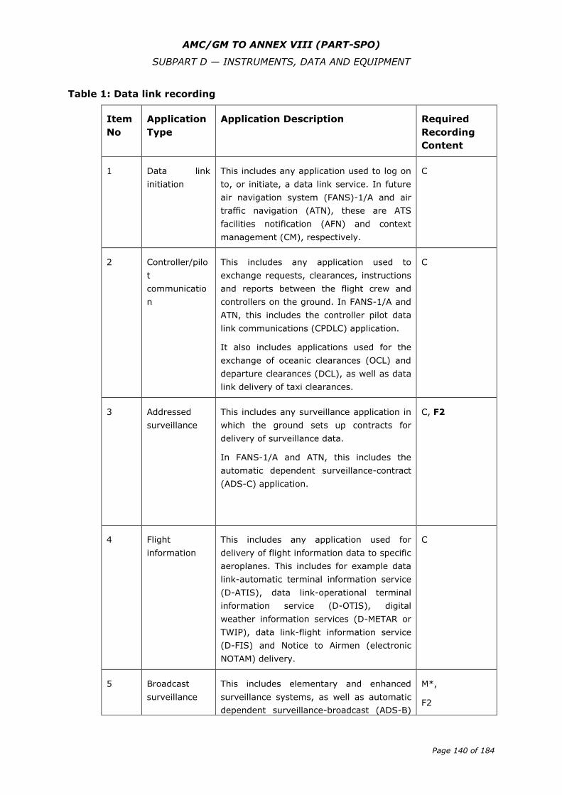
AMC/GM TO ANNEX VIII (PART-SPO)
SUBPART D — INSTRUMENTS, DATA AND EQUIPMENT
Page 140 of 184
Table 1: Data link recording
Item
No
Application
Type
Application Description Required
Recording
Content
1 Data link
initiation
This includes any application used to log on
to, or initiate, a data link service. In future
air navigation system (FANS)-1/A and air
traffic navigation (ATN), these are ATS
facilities notification (AFN) and context
management (CM), respectively.
C
2 Controller/pilo
t
communicatio
n
This includes any application used to
exchange requests, clearances, instructions
and reports between the flight crew and
controllers on the ground. In FANS-1/A and
ATN, this includes the controller pilot data
link communications (CPDLC) application.
It also includes applications used for the
exchange of oceanic clearances (OCL) and
departure clearances (DCL), as well as data
link delivery of taxi clearances.
C
3 Addressed
surveillance
This includes any surveillance application in
which the ground sets up contracts for
delivery of surveillance data.
In FANS-1/A and ATN, this includes the
automatic dependent surveillance-contract
(ADS-C) application.
C, F2
4 Flight
information
This includes any application used for
delivery of flight information data to specific
aeroplanes. This includes for example data
link-automatic terminal information service
(D-ATIS), data link-operational terminal
information service (D-OTIS), digital
weather information services (D-METAR or
TWIP), data link-flight information service
(D-FIS) and Notice to Airmen (electronic
NOTAM) delivery.
C
5 Broadcast
surveillance
This includes elementary and enhanced
surveillance systems, as well as automatic
dependent surveillance-broadcast (ADS-B)
M*,
F2
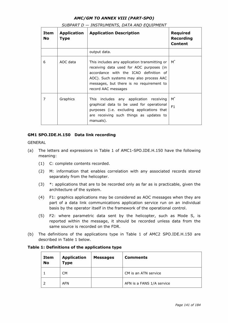
AMC/GM TO ANNEX VIII (PART-SPO)
SUBPART D — INSTRUMENTS, DATA AND EQUIPMENT
Page 141 of 184
Item
No
Application
Type
Application Description Required
Recording
Content
output data.
6 AOC data This includes any application transmitting or
receiving data used for AOC purposes (in
accordance with the ICAO definition of
AOC). Such systems may also process AAC
messages, but there is no requirement to
record AAC messages
M*
7 Graphics This includes any application receiving
graphical data to be used for operational
purposes (i.e. excluding applications that
are receiving such things as updates to
manuals).
M*
F1
GM1 SPO.IDE.H.150 Data link recording
GENERAL
(a) The letters and expressions in Table 1 of AMC1-SPO.IDE.H.150 have the following
meaning:
(1) C: complete contents recorded.
(2) M: information that enables correlation with any associated records stored
separately from the helicopter.
(3) *: applications that are to be recorded only as far as is practicable, given the
architecture of the system.
(4) F1: graphics applications may be considered as AOC messages when they are
part of a data link communications application service run on an individual
basis by the operator itself in the framework of the operational control.
(5) F2: where parametric data sent by the helicopter, such as Mode S, is
reported within the message, it should be recorded unless data from the
same source is recorded on the FDR.
(b) The definitions of the applications type in Table 1 of AMC2 SPO.IDE.H.150 are
described in Table 1 below.
Table 1: Definitions of the applications type
Item
No
Application
Type
Messages Comments
1 CM CM is an ATN service
2 AFN AFN is a FANS 1/A service
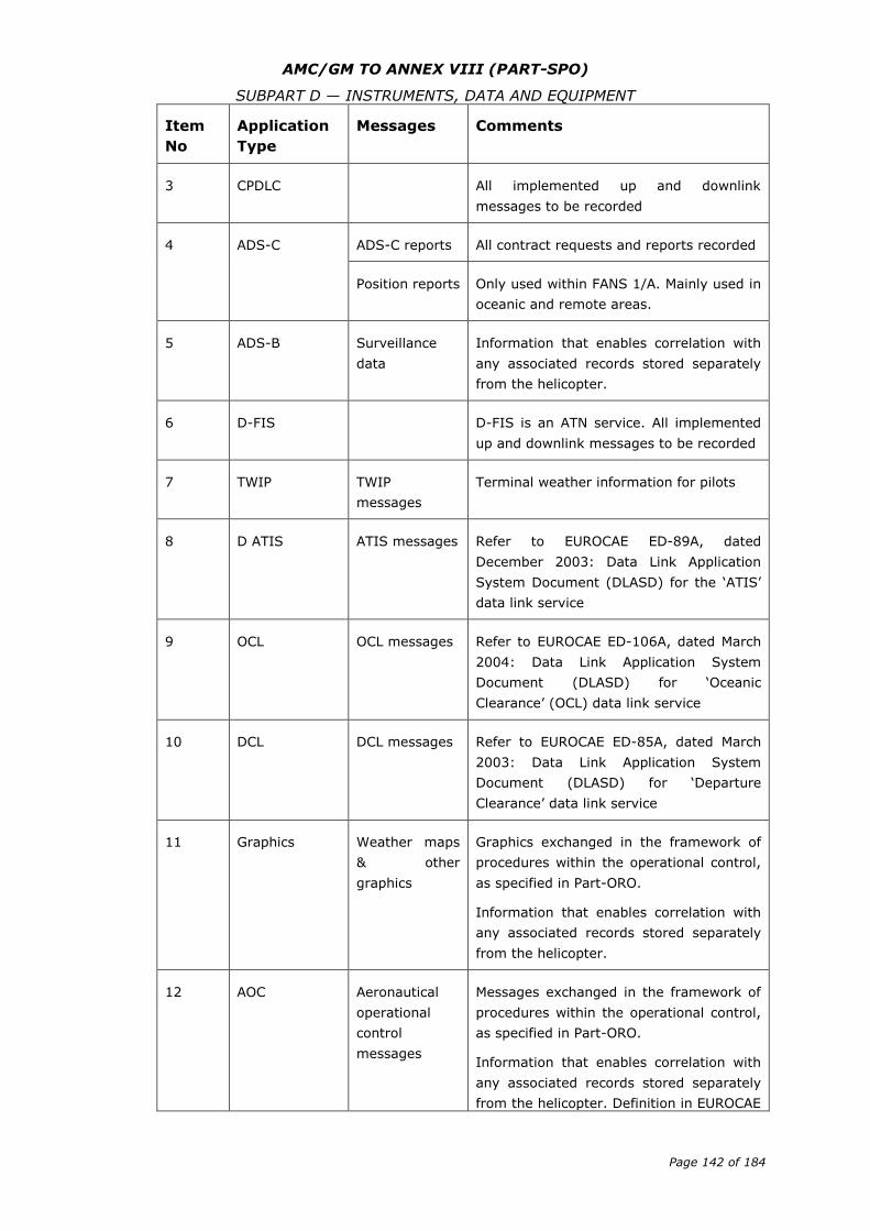
AMC/GM TO ANNEX VIII (PART-SPO)
SUBPART D — INSTRUMENTS, DATA AND EQUIPMENT
Page 142 of 184
Item
No
Application
Type
Messages Comments
3 CPDLC All implemented up and downlink
messages to be recorded
4 ADS-C ADS-C reports All contract requests and reports recorded
Position reports Only used within FANS 1/A. Mainly used in
oceanic and remote areas.
5 ADS-B Surveillance
data
Information that enables correlation with
any associated records stored separately
from the helicopter.
6 D-FIS D-FIS is an ATN service. All implemented
up and downlink messages to be recorded
7 TWIP TWIP
messages
Terminal weather information for pilots
8 D ATIS ATIS messages Refer to EUROCAE ED-89A, dated
December 2003: Data Link Application
System Document (DLASD) for the ‘ATIS’
data link service
9 OCL OCL messages Refer to EUROCAE ED-106A, dated March
2004: Data Link Application System
Document (DLASD) for ‘Oceanic
Clearance’ (OCL) data link service
10 DCL DCL messages Refer to EUROCAE ED-85A, dated March
2003: Data Link Application System
Document (DLASD) for ‘Departure
Clearance’ data link service
11 Graphics Weather maps
& other
graphics
Graphics exchanged in the framework of
procedures within the operational control,
as specified in Part-ORO.
Information that enables correlation with
any associated records stored separately
from the helicopter.
12 AOC Aeronautical
operational
control
messages
Messages exchanged in the framework of
procedures within the operational control,
as specified in Part-ORO.
Information that enables correlation with
any associated records stored separately
from the helicopter. Definition in EUROCAE
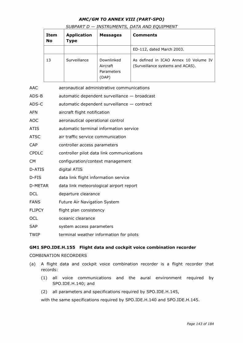
AMC/GM TO ANNEX VIII (PART-SPO)
SUBPART D — INSTRUMENTS, DATA AND EQUIPMENT
Page 143 of 184
Item
No
Application
Type
Messages Comments
ED-112, dated March 2003.
13 Surveillance Downlinked
Aircraft
Parameters
(DAP)
As defined in ICAO Annex 10 Volume IV
(Surveillance systems and ACAS).
AAC aeronautical administrative communications
ADS-B automatic dependent surveillance — broadcast
ADS-C automatic dependent surveillance — contract
AFN aircraft flight notification
AOC aeronautical operational control
ATIS automatic terminal information service
ATSC air traffic service communication
CAP controller access parameters
CPDLC controller pilot data link communications
CM configuration/context management
D-ATIS digital ATIS
D-FIS data link flight information service
D-METAR data link meteorological airport report
DCL departure clearance
FANS Future Air Navigation System
FLIPCY flight plan consistency
OCL oceanic clearance
SAP system access parameters
TWIP terminal weather information for pilots
GM1 SPO.IDE.H.155 Flight data and cockpit voice combination recorder
COMBINATION RECORDERS
(a) A flight data and cockpit voice combination recorder is a flight recorder that
records:
(1) all voice communications and the aural environment required by
SPO.IDE.H.140; and
(2) all parameters and specifications required by SPO.IDE.H.145,
with the same specifications required by SPO.IDE.H.140 and SPO.IDE.H.145.
AMC/GM TO ANNEX VIII (PART-SPO)
SUBPART D — INSTRUMENTS, DATA AND EQUIPMENT
Page 144 of 184
(b) In addition, a flight data and cockpit voice combination recorder may record data
link communication messages and related information required by SPO.IDE.H.150.
AMC2 SPO.IDE.H.160 Seats, seat safety belts and restraint systems
UPPER TORSO RESTRAINT SYSTEM
The following systems are deemed to be compliant with the requirement for an upper
torso restraint system:
(a) For other-than-complex helicopters, a seat belt with a diagonal shoulder strap;
(b) For all helicopters, a restraint system having a seat belt and two shoulder straps
that may be used independently.
(c) For all helicopters, a restraint system having a seat belt, two shoulder straps and
additional straps that may be used independently.
SEAT BELT
A seat belt with a diagonal shoulder strap (three anchorage points) is deemed to be
compliant with the requirement for a seat belt (two anchorage points).
AMC1 SPO.IDE.H.165 First-aid kit
CONTENT OF FIRST-AID KITS — OTHER-THAN-COMPLEX MOTOR-POWERED
HELICOPTERS
(a) First-aid kits should be equipped with appropriate and sufficient medications and
instrumentation. However, these kits should be amended by the operator according
to the characteristics of the operation (scope of operation, flight duration, number
and demographics of persons on board, etc.).
(b) The following should be included in the FAKs:
(1) bandages (assorted sizes),
(2) burns dressings (large and small),
(3) wound dressings (large and small),
(4) adhesive dressings (assorted sizes),
(5) antiseptic wound cleaner,
(6) safety scissors, and
(7) disposable gloves.
AMC2 SPO.IDE.H.165 First-aid kit
CONTENT OF FIRST-AID KIT — COMPLEX MOTOR-POWERED HELICOPTERS
(a) First-aid kits should be equipped with appropriate and sufficient medications and
instrumentation. However, these kits should be amended by the operator according
to the characteristics of the operation (scope of operation, flight duration, number
and demographics of persons on board etc.).
(b) The following should be included in the FAKs:
(1) Equipment:
AMC/GM TO ANNEX VIII (PART-SPO)
SUBPART D — INSTRUMENTS, DATA AND EQUIPMENT
Page 145 of 184
(i) bandages (assorted sizes);
(ii) burns dressings (unspecified);
(iii) wound dressings (large and small);
(iv) adhesive dressings (assorted sizes);
(v) adhesive tape;
(vi) adhesive wound closures;
(vii) safety pins;
(viii) safety scissors;
(ix) antiseptic wound cleaner;
(x) disposable resuscitation aid;
(xi) disposable gloves;
(xii) tweezers: splinter; and
(xiii) thermometers (non-mercury).
(2) Medications:
(i) simple analgesic (may include liquid form);
(ii) antiemetic;
(iii) nasal decongestant;
(iv) gastrointestinal antacid, in the case of helicopters carrying more than
nine persons;
(v) anti-diarrhoeal medication in the case of helicopters carrying more than
nine persons; and
(vi) antihistamine.
(3) Other:
(i) a list of contents in at least two languages (English and one other). This
should include information on the effects and side effects of medications
carried;
(ii) first-aid handbook;
(iii) medical incident report form; and
(iv) biohazard disposal bags.
(4) An eye irrigator, although not required to be carried in the FAK, should,
where possible, be available for use on the ground.
AMC3 SPO.IDE.H.165 First-aid kit
MAINTENANCE OF FIRST-AID KIT
To be kept up to date, the first-aid kit should be:
(a) inspected periodically to confirm, to the extent possible, that contents are
maintained in the condition necessary for their intended use;
(b) replenished at regular intervals, in accordance with instructions contained on their
labels, or as circumstances warrant; and
AMC/GM TO ANNEX VIII (PART-SPO)
SUBPART D — INSTRUMENTS, DATA AND EQUIPMENT
Page 146 of 184
(c) replenished after use in-flight at the first opportunity where replacement items are
available.
AMC1 SPO.IDE.H.175 Supplemental oxygen — non-pressurised helicopters
DETERMINATION OF OXYGEN
The amount of oxygen should be determined on the basis of cabin pressure altitude and
flight duration, consistent with the operating procedures, including emergency,
procedures, established for each operation and the routes to be flown as specified in the
AFM.
AMC1 SPO.IDE.H.180 Hand fire extinguishers
NUMBER, LOCATION AND TYPE
(a) The number and location of hand fire extinguishers should be such as to provide
adequate availability for use, account being taken of the number and size of the
cabin compartments, the need to minimise the hazard of toxic gas concentrations
and the location of toilets, galleys, etc. These considerations may result in the
number of fire extinguishers being greater than the minimum required.
(b) There should be at least one hand fire extinguisher installed in the flight crew
compartment and this should be suitable for fighting both flammable fluid and
electrical equipment fires. Additional hand fire extinguishers may be required for
the protection of other compartments accessible to the flight crew or task specialist
in flight. Dry chemical fire extinguishers should not be used in the flight crew
compartment, or in any compartment not separated by a partition from the flight
crew compartment, because of the adverse effect on vision during discharge and, if
conductive, interference with electrical contacts by the chemical residues.
(c) Where only one hand fire extinguisher is required in the cabin compartments, it
should be located near the task specialist’s station, where provided.
(d) Where two or more hand fire extinguishers are required in the cabin compartments
and their location is not otherwise dictated by consideration of (a), an extinguisher
should be located near each end of the cabin with the remainder distributed
throughout the cabin as evenly as is practicable.
(e) Unless an extinguisher is clearly visible, its location should be indicated by a
placard or sign. Appropriate symbols may also be used to supplement such a
placard or sign.
AMC1 SPO.IDE.H.185 Marking of break-in points
COLOUR AND CORNERS’ MARKING
(a) The colour of the markings should be red or yellow and, if necessary, should be
outlined in white to contrast with the background.
(b) If the corner markings are more than 2 m apart, intermediate lines 9 cm x 3 cm
should be inserted so that there is no more than 2 m between adjacent markings.
AMC/GM TO ANNEX VIII (PART-SPO)
SUBPART D — INSTRUMENTS, DATA AND EQUIPMENT
Page 147 of 184
AMC1 SPO.IDE.H.190 Emergency locator transmitter (ELT)
BATTERIES
(a) All batteries used in ELTs or PLBs should be replaced (or recharged if the battery is
rechargeable) when the equipment has been in use for more than 1 cumulative
hour or in the following cases:
(1) Batteries specifically designed for use in ELTs and having an airworthiness
release certificate (EASA Form 1 or equivalent) should be replaced (or
recharged, if the battery is rechargeable) before the end of their useful life in
accordance with the maintenance instructions applicable to the ELT.
(2) Standard batteries manufactured in accordance with an industry standard and
not having an airworthiness release certificate (EASA Form 1 or equivalent),
when used in ELTs should be replaced (or recharged if the battery is
rechargeable) when 50 % of their useful life (or for rechargeable, 50 % of
their useful life of charge), as established by the battery manufacturer, has
expired.
(3) All batteries used in PLBs should be replaced (or recharged, if the battery is
rechargeable) when 50 % of their useful life (or for rechargeable 50 % of
their useful life of charge), as established by the battery manufacturer, has
expired.
(4) The battery useful life (or useful life of charge) criteria in (1),(2) and (3) do
not apply to batteries (such as water-activated batteries) that are essentially
unaffected during probable storage intervals.
(b) The new expiry date for a replaced (or recharged) battery should be legibly marked
on the outside of the equipment.
AMC2 SPO.IDE.H.190 Emergency locator transmitter (ELT)
TYPES OF ELT AND GENERAL TECHNICAL SPECIFICATIONS
(a) The ELT required by this provision should be one of the following:
(1) Automatic fixed (ELT(AF)). An automatically activated ELT that is
permanently attached to an aircraft and is designed to aid SAR teams in
locating the crash site.
(2) Automatic portable (ELT(AP)). An automatically activated ELT that is rigidly
attached to an aircraft before a crash, but is readily removable from the
aircraft after a crash. It functions as an ELT during the crash sequence. If the
ELT does not employ an integral antenna, the aircraft-mounted antenna may
be disconnected and an auxiliary antenna (stored on the ELT case) attached
to the ELT. The ELT can be tethered to a survivor or a life-raft. This type of
ELT is intended to aid SAR teams in locating the crash site or survivor(s).
(3) Automatic deployable (ELT(AD)). An ELT that is rigidly attached to the aircraft
before the crash and that is automatically ejected, deployed and activated by
an impact, and, in some cases, also by hydrostatic sensors. Manual
deployment is also provided. This type of ELT should float in water and is
intended to aid SAR teams in locating the crash site.
AMC/GM TO ANNEX VIII (PART-SPO)
SUBPART D — INSTRUMENTS, DATA AND EQUIPMENT
Page 148 of 184
(4) Survival ELT (ELT(S)). An ELT that is removable from an aircraft, stowed so
as to facilitate its ready use in an emergency, and manually activated by a
survivor. An ELT(S) may be activated manually or automatically (e.g. by
water activation). It should be designed to be tethered to a life-raft or a
survivor.
(b) To minimise the possibility of damage in the event of crash impact, the automatic
ELT should be rigidly fixed to the aircraft structure, as far aft as is practicable, with
its antenna and connections arranged so as to maximise the probability of the
signal being transmitted after a crash.
(c) Any ELT carried should operate in accordance with the relevant provisions of ICAO
Annex 10, Volume III and should be registered with the national agency
responsible for initiating search and rescue or other nominated agency.
AMC3 SPO.IDE.H.190 Emergency locator transmitter (ELT)
PLB TECHNICAL SPECIFICATIONS
(a) A personal locator beacon (PLB) should have a built-in GNSS receiver with a
cosmicheskaya sistyema poiska avariynich sudov — search and rescue satellite-
aided tracking (COSPAS-SARSAT) type approval number. However, devices with a
COSPAS-SARSAT with a number belonging to series 700 are excluded as this series
of numbers identifies the special-use beacons not meeting all the technical
requirements and all the tests specified by COSPAS-SARSAT.
(b) Any PLB carried should be registered with the national agency responsible for
initiating search and rescue or other nominated agency.
AMC4 SPO.IDE.H.190 Emergency locator transmitter (ELT)
BRIEFING ON PLB USE
When a PLB is carried by a task specialist, he/she should be briefed on its characteristics
and use by the pilot-in-command before the flight.
GM1 SPO.IDE.H.190 Emergency locator transmitter (ELT)
TERMINOLOGY
(a) An ELT is a generic term describing equipment that broadcasts distinctive signals
on designated frequencies and, depending on application, may be activated by
impact or may be manually activated.
(b) A PLB is an emergency beacon other than an ELT that broadcasts distinctive signals
on designated frequencies, is standalone, portable and is manually activated by the
survivors.
GM2 SPO.IDE.H.190 Emergency locator transmitter (ELT)
MAXIMUM CERTIFIED SEATING CONFIGURATION
The maximum certified seating configuration does not include flight crew seats.
AMC/GM TO ANNEX VIII (PART-SPO)
SUBPART D — INSTRUMENTS, DATA AND EQUIPMENT
Page 149 of 184
AMC1 SPO.IDE.H.195 Flight over water — other-than-complex motor-powered
helicopters
ACCESSIBILITY OF LIFE-JACKETS
The life-jacket, if not worn, should be accessible from the seat or station of the person
for whose use it is provided, with a safety belt or a restraint system fastened.
MEANS OF ILLUMINATION FOR LIFE-JACKETS
The means of electric illumination should be a survivor locator light as defined in the
applicable ETSO issued by the Agency or equivalent.
RISK ASSESSMENT
(a) When conducting the risk assessment, the pilot-in-command should base his/her
decision, as far as is practicable, on the Implementing Rules and AMCs applicable
to the operation of the helicopter.
(b) The pilot-in-command should, for determining the risk, take the following operating
environment and conditions into account:
(1) sea state;
(2) sea and air temperatures;
(3) the distance from land suitable for making an emergency landing; and
(4) the availability of search and rescue facilities.
GM1 SPO.IDE.H.195 Flight over water — other-than-complex motor-powered
helicopters
SEAT CUSHIONS
Seat cushions are not considered to be flotation devices.
AMC1 SPO.IDE.H.197 Life-jackets — complex motor-powered helicopters
ACCESSIBILITY OF LIFE-JACKETS
The life-jacket, if not worn, should be accessible from the seat or station of the person
for whose use it is provided, with a safety belt or a restraint system fastened.
MEANS OF ILLUMINATION FOR LIFE-JACKETS
The means of electric illumination should be a survivor locator light as defined in the
applicable ETSO issued by the Agency or equivalent.
GM1 SPO.IDE.H.197 Life-jackets – complex motor-powered helicopters
SEAT CUSHIONS
Seat cushions are not considered to be flotation devices.
GM1 SPO.IDE.H.198 Survival suits — complex motor-powered helicopters
ESTIMATING SURVIVAL TIME
(a) Introduction
AMC/GM TO ANNEX VIII (PART-SPO)
SUBPART D — INSTRUMENTS, DATA AND EQUIPMENT
Page 150 of 184
(1) A person accidentally immersed in cold seas (typically offshore Northern
Europe) will have a better chance of survival if he/she is wearing an effective
survival suit in addition to a life-jacket. By wearing the survival suit, he/she
can slow down the rate which his/her body temperature falls and,
consequently, protect himself/herself from the greater risk of drowning
brought about by incapacitation due to hypothermia.
(2) The complete survival suit system – suit, life-jacket and clothes worn under
the suit – should be able to keep the wearer alive long enough for the rescue
services to find and recover him/her. In practice the limit is about 3 hours. If
a group of persons in the water cannot be rescued within this time they are
likely to have become so scattered and separated that location will be
extremely difficult, especially in the rough water typical of Northern European
sea areas. If it is expected that in water protection could be required for
periods greater than 3 hours, improvements should, rather, be sought in the
search and rescue procedures than in the immersion suit protection.
(b) Survival times
(1) The aim should be to ensure that a person in the water can survive long
enough to be rescued, i.e. the survival time should be greater than the likely
rescue time. The factors affecting both times are shown in Figure 1. The
figure emphasises that survival time is influenced by many factors, physical
and human. Some of the factors are relevant to survival in cold water and
some are relevant in water at any temperature.
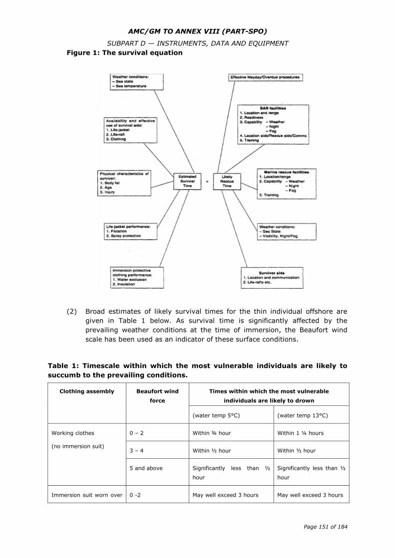
AMC/GM TO ANNEX VIII (PART-SPO)
SUBPART D — INSTRUMENTS, DATA AND EQUIPMENT
Page 151 of 184
Figure 1: The survival equation
(2) Broad estimates of likely survival times for the thin individual offshore are
given in Table 1 below. As survival time is significantly affected by the
prevailing weather conditions at the time of immersion, the Beaufort wind
scale has been used as an indicator of these surface conditions.
Table 1: Timescale within which the most vulnerable individuals are likely to
succumb to the prevailing conditions.
Clothing assembly Beaufort wind
force
Times within which the most vulnerable
individuals are likely to drown
(water temp 5°C) (water temp 13°C)
Working clothes
(no immersion suit)
0 – 2 Within ¾ hour Within 1 ¼ hours
3 – 4 Within ½ hour Within ½ hour
5 and above Significantly less than ½
hour
Significantly less than ½
hour
Immersion suit worn over 0 -2 May well exceed 3 hours May well exceed 3 hours
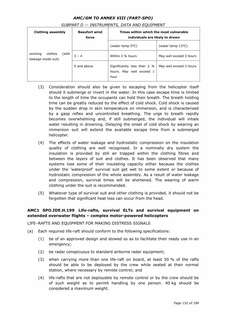
AMC/GM TO ANNEX VIII (PART-SPO)
SUBPART D — INSTRUMENTS, DATA AND EQUIPMENT
Page 152 of 184
Clothing assembly Beaufort wind
force
Times within which the most vulnerable
individuals are likely to drown
(water temp 5°C) (water temp 13°C)
working clothes (with
leakage inside suit) 3 – 4 Within 2 ¾ hours May well exceed 3 hours
5 and above Significantly less than 2 ¾
hours. May well exceed 1
hour
May well exceed 3 hours
(3) Consideration should also be given to escaping from the helicopter itself
should it submerge or invert in the water. In this case escape time is limited
to the length of time the occupants can hold their breath. The breath holding
time can be greatly reduced by the effect of cold shock. Cold shock is caused
by the sudden drop in skin temperature on immersion, and is characterised
by a gasp reflex and uncontrolled breathing. The urge to breath rapidly
becomes overwhelming and, if still submerged, the individual will inhale
water resulting in drowning. Delaying the onset of cold shock by wearing an
immersion suit will extend the available escape time from a submerged
helicopter.
(4) The effects of water leakage and hydrostatic compression on the insulation
quality of clothing are well recognised. In a nominally dry system the
insulation is provided by still air trapped within the clothing fibres and
between the layers of suit and clothes. It has been observed that many
systems lose some of their insulating capacity either because the clothes
under the 'waterproof' survival suit get wet to some extent or because of
hydrostatic compression of the whole assembly. As a result of water leakage
and compression, survival times will be shortened. The wearing of warm
clothing under the suit is recommended.
(5) Whatever type of survival suit and other clothing is provided, it should not be
forgotten that significant heat loss can occur from the head.
AMC1 SPO.IDE.H.199 Life-rafts, survival ELTs and survival equipment on
extended overwater flights – complex motor-powered helicopters
LIFE–RAFTS AND EQUIPMENT FOR MAKING DISTRESS SIGNALS
(a) Each required life-raft should conform to the following specifications:
(1) be of an approved design and stowed so as to facilitate their ready use in an
emergency;
(2) be radar conspicuous to standard airborne radar equipment;
(3) when carrying more than one life-raft on board, at least 50 % of the rafts
should be able to be deployed by the crew while seated at their normal
station, where necessary by remote control; and
(4) life-rafts that are not deployable by remote control or by the crew should be
of such weight as to permit handling by one person. 40 kg should be
considered a maximum weight.
AMC/GM TO ANNEX VIII (PART-SPO)
SUBPART D — INSTRUMENTS, DATA AND EQUIPMENT
Page 153 of 184
(b) Each required life-raft should contain at least the following:
(1) one approved survivor locator light;
(2) one approved visual signalling device;
(3) one canopy (for use as a sail, sunshade or rain catcher) or other mean to
protect occupants from the elements;
(4) one radar reflector;
(5) one 20 m retaining line designed to hold the life-raft near the helicopter but
to release it if the helicopter becomes totally submerged;
(6) one sea anchor; and
(7) one survival kit, appropriately equipped for the route to be flown, which
should contain at least the following:
(i) one life-raft repair kit;
(ii) one bailing bucket;
(iii) one signalling mirror;
(iv) one police whistle;
(v) one buoyant raft knife;
(vi) one supplementary means of inflation;
(vii) sea sickness tablets;
(viii) one first-aid kit;
(ix) one portable means of illumination;
(x) 500 ml of pure water and one sea water desalting kit; and
(xi) one comprehensive illustrated survival booklet in an appropriate
language.
AMC1 SPO.IDE.H.200 Survival equipment
ADDITIONAL SURVIVAL EQUIPMENT
(a) The following additional survival equipment should be carried when required:
(1) 500 ml of water for each four, or fraction of four, persons on board;
(2) one knife;
(3) first-aid equipment; and
(4) one set of air/ground codes.
(b) In addition, when polar conditions are expected, the following should be carried:
(1) a means of melting snow;
(2) one snow shovel and one ice saw;
(3) sleeping bags for use by 1/3 of all persons on board and space blankets for
the remainder or space blankets for all persons on board; and
(4) one arctic/polar suit for each crew member.
AMC/GM TO ANNEX VIII (PART-SPO)
SUBPART D — INSTRUMENTS, DATA AND EQUIPMENT
Page 154 of 184
(c) If any item of equipment contained in the above list is already carried on board the
aircraft in accordance with another requirement, there is no need for this to be
duplicated.
AMC1 SPO.IDE.H.200(b) Survival equipment
SURVIVAL ELT
An ELT(AP) may be used to replace one required ELT(S) provided that it meets the
ELT(S) requirements. A water-activated ELT(S) is not an ELT(AP).
GM1 SPO.IDE.H.200 Survival equipment
SIGNALLING EQUIPMENT
The signalling equipment for making distress signals is described in ICAO Annex 2, Rules
of the Air.
GM2 SPO.IDE.H.200 Survival equipment
AREAS IN WHICH SEARCH AND RESCUE WOULD BE ESPECIALLY DIFFICULT
The expression ‘areas in which search and rescue would be especially difficult’ should be
interpreted, in this context, as meaning:
(a) areas so designated by the authority responsible for managing search and rescue;
or
(b) areas that are largely uninhabited and where:
(1) the authority referred to in (a) has not published any information to confirm
whether search and rescue would be or would not be especially difficult; and
(2) the authority referred to in (a) does not, as a matter of policy, designate
areas as being especially difficult for search and rescue.
AMC1 SPO.IDE.H.201 Additional requirements for helicopters conducting
offshore operations in a hostile sea area — complex motor-powered helicopters
INSTALLATION OF THE LIFE RAFT
(a) Projections on the exterior surface of the helicopter, that are located in a zone
delineated by boundaries that are 1.22 m (4 ft) above and 0.61 m (2 ft) below the
established static water line could cause damage to a deployed life-raft. Examples
of projections which need to be considered are aerials, overboard vents,
unprotected split-pin tails, guttering and any projection sharper than a three
dimensional right angled corner.
(b) While the boundaries specified in (1) are intended as a guide, the total area that
should be considered should also take into account the likely behaviour of the life-
raft after deployment in all sea states up to the maximum in which the helicopter is
capable of remaining upright.
(c) Wherever a modification or alteration is made to a helicopter within the boundaries
specified, the need to prevent the modification or alteration from causing damage
to a deployed life-raft should be taken into account in the design.
AMC/GM TO ANNEX VIII (PART-SPO)
SUBPART D — INSTRUMENTS, DATA AND EQUIPMENT
Page 155 of 184
(d) Particular care should also be taken during routine maintenance to ensure that
additional hazards are not introduced by, for example, leaving inspection panels
with sharp corners proud of the surrounding fuselage surface, or allowing door sills
to deteriorate to a point where sharp edges become a hazard.
GM1 SPO.IDE.H.202 Helicopters certificated for operating on water —
miscellaneous equipment
INTERNATIONAL REGULATIONS FOR PREVENTING COLLISIONS AT SEA
International Regulations for Preventing Collisions at Sea are those that were published
by the International Maritime Organisation (IMO) in 1972.
AMC1 SPO.IDE.H.203 All helicopters on flights over water — ditching
EMERGENCY FLOTATION EQUIPMENT
The same considerations of AMC1 SPO.IDE.H.201 should apply in respect of emergency
flotation equipment.
GM1 SPO.IDE.H.205 Individual protective equipment
TYPES OF INDIVIDUAL PROTECTIVE EQUIPMENT
Personal protective equipment should include, but is not limited to: flying suits, gloves,
helmets, protective shoes, etc.
AMC1 SPO.IDE.H.210 Headset
GENERAL
(a) A headset consists of a communication device that includes two earphones to
receive and a microphone to transmit audio signals to the helicopter’s
communication system. To comply with the minimum performance requirements,
the earphones and microphone should match the communication system’s
characteristics and the flight crew compartment environment. The headset should
be adequately adjustable in order to fit the flight crew’s head. Headset boom
microphones should be of the noise cancelling type.
(b) If the intention is to utilise noise cancelling earphones, the operator should ensure
that the earphones do not attenuate any aural warnings or sounds necessary for
alerting the flight crew on matters related to the safe operation of the helicopter.
GM1 SPO.IDE.H.210 Headset
GENERAL
The term ‘headset’ includes any aviation helmet incorporating headphones and
microphone worn by a flight crew member.
AMC/GM TO ANNEX VIII (PART-SPO)
SUBPART D — INSTRUMENTS, DATA AND EQUIPMENT
Page 156 of 184
GM1 SPO.IDE.H.215 Radio communication equipment
APPLICABLE AIRSPACE REQUIREMENTS
For helicopters being operated under European air traffic control, the applicable airspace
requirements include the Single European Sky legislation.
AMC1 SPO.IDE.H.220 Navigation equipment
NAVIGATION WITH VISUAL REFERENCE TO LANDMARKS — OTHER-THAN-COMPLEX
HELICOPTERS
Where other-than-complex helicopters, with the surface in sight, can proceed according
to the ATS flight plan by navigation with visual reference to landmarks, no additional
equipment is needed to comply with SPO.IDE.H.220 (a)(1).
AMC1 SPO.IDE.H.225 Transponder
GENERAL
(a) The SSR transponders of helicopters being operated under European air traffic
control should comply with any applicable Single European Sky legislation.
(b) If the Single European Sky legislation is not applicable, the SSR transponders
should operate in accordance with the relevant provisions of Volume IV of ICAO
Annex 10.
AMC/GM TO ANNEX VIII (PART-SPO)
SUBPART D — INSTRUMENTS, DATA AND EQUIPMENT
Page 157 of 184
Section 3 — Sailplanes
GM1 SPO.IDE.S.100(a) Instruments and equipment — general
APPLICABLE AIRWORTHINESS REQUIREMENTS
The applicable airworthiness requirements for approval of instruments and equipment
required by this Part are the following:
(a) Commission Regulation (EU) No 748/2012 for sailplanes registered in the EU; and
(b) Airworthiness requirements of the state of registry for sailplanes registered outside
the EU.
GM1 SPO.IDE.S.100(b) Instruments and equipment — general
REQUIRED INSTRUMENTS AND EQUIPMENT THAT DO NOT NEED TO BE APPROVED IN
ACCORDANCE WITH THE APPLICABLE AIRWORTHINESS REQUIREMENTS
The functionality of non-installed instruments and equipment required by this Subpart
and that do not need an equipment approval, as listed in SPO.IDE.S.100(b), should be
checked against recognised industry standards appropriate to the intended purpose. The
operator is responsible for ensuring the maintenance of these instruments and
equipment.
GM1 SPO.IDE.S.100(c) Instruments and equipment — general
NOT REQUIRED INSTRUMENTS AND EQUIPMENT THAT DO NOT NEED TO BE APPROVED
IN ACCORDANCE WITH THE APPLICABLE AIRWORTHINESS REQUIREMENTS, BUT ARE
CARRIED ON A FLIGHT
(a) The provision of this paragraph does not exempt any installed instrument or item
of equipment from complying with the applicable airworthiness requirements. In
this case, the installation should be approved as required in the applicable
airworthiness requirements and should comply with the applicable airworthiness
codes.
(c) The failure of additional non-installed instruments or equipment not required by
this Part or by the applicable airworthiness requirements or any applicable airspace
requirements should not adversely affect the airworthiness and/or the safe
operation of the sailplane. Examples may be portable electronic devices carried by
crew members or task specialists.
AMC1 SPO.IDE.S.115 & SPO.IDE.S.120 Operations under VFR & Cloud flying —
flight and navigational instruments
INTEGRATED INSTRUMENTS
(a) Individual equipment requirements may be met by combinations of instruments or
by integrated flight systems or by a combination of parameters on electronic
displays. The information so available to each required pilot should not be less than
that required in the applicable operational requirements, and the equivalent safety
of the installation should be approved during type certification of the sailplane for
the intended type of operation.
AMC/GM TO ANNEX VIII (PART-SPO)
SUBPART D — INSTRUMENTS, DATA AND EQUIPMENT
Page 158 of 184
(b) The means of measuring and indicating turn and slip and sailplane attitude may be
met by combinations of instruments or by integrated flight director systems,
provided that the safeguards against total failure, inherent in the three separate
instruments, are retained.
AMC1 SPO.IDE.S.115(a)(1) & SPO.IDE.S.120(a) Operations under VFR & Cloud
flying — flight and navigational instruments
MEANS OF MEASURING AND DISPLAYING MAGNETIC HEADING
The means of measuring and displaying magnetic direction should be a magnetic
compass or equivalent.
AMC1 SPO.IDE.S.115(a)(2) & SPO.IDE.S.120(b) Operations under VFR & Cloud
flying — flight and navigational instruments
MEANS OF MEASURING AND DISPLAYING THE TIME
A means of measuring and displaying the time in hours, minutes and seconds may be a
wrist watch capable of the same functions.
AMC1 SPO.IDE.S.115(a)(3) & SPO.IDE.S.120(c) Operations under VFR & Cloud
flying — flight and navigational instruments
CALIBRATION OF THE MEANS FOR MEASURING AND DISPLAYING PRESSURE ALTITUDE
(a) The instrument measuring and displaying pressure altitude should be of a sensitive
type calibrated in feet (ft), with a sub-scale setting, calibrated in
hectopascals/millibars, adjustable for any barometric pressure likely to be set
during flight.
(b) Calibration in metres (m) is also acceptable.
AMC1 SPO.IDE.S.115(a)(4) & SPO.IDE.S.120(d) Operations under VFR & Cloud
flying — flight and navigational instruments
CALIBRATION OF THE INSTRUMENT INDICATING AIRSPEED
(a) The instrument indicating airspeed should be calibrated in knots (kt).
(b) Calibration in kilometres (km) per hour or in miles per hour (mph) is also
acceptable.
AMC1 SPO.IDE.S.115(b)(2) Operations under VFR — flight and navigational
instruments
SLIP INDICATION
The means of measuring and displaying slip may be a yaw string for operations under
VFR.
AMC/GM TO ANNEX VIII (PART-SPO)
SUBPART D — INSTRUMENTS, DATA AND EQUIPMENT
Page 159 of 184
GM1 SPO.IDE.S.115(b) Operations under VFR — flight and navigational
instruments
CONDITIONS WHERE THE SAILPLANE CANNOT BE MAINTAINED IN A DESIRED
ATTITUDE WITHOUT REFERENCE TO ONE OR MORE ADDITIONAL INSTRUMENTS
Sailplanes operating in conditions where the sailplane cannot be maintained in a desired
attitude without reference to one or more additional instruments means a condition that
is still under VFR (under VMC) though where there is no external reference such as the
natural horizon or a coastline, that would allow the attitude to be maintained. Such
conditions may occur over water, a desert or snow-covered areas where the colour of
the surface cannot be distinguished from the colour of the sky and therefore no external
reference is available. Cloud flying is not considered to be one of these conditions.
AMC1 SPO.IDE.S.125 Seats and restraint systems
UPPER TORSO RESTRAINT SYSTEM
(a) A seat belt with upper torso restraint system should have four anchorage points
and should include shoulder straps (two anchorage points) and a seat belt (two
anchorage points), which may be used independently.
(b) A restraint system having five anchorage points is deemed to be compliant with the
requirement for seat belt with upper torso restraint system with four anchorage
points.
AMC1 SPO.IDE.S.135 Flight over water
MEANS OF ILLUMINATION FOR LIFE-JACKETS
Each life-jacket or equivalent individual flotation device should be equipped with a means
of electric illumination for the purpose of facilitating the location of persons.
RISK ASSESSMENT
(a) When conducting the risk assessment, the pilot-in-command should base his/her
decision, as far as is practicable, on the Implementing Rules and AMCs applicable
to the operation of the sailplane.
(b) The pilot-in-command should, for determining the risk, take the following operating
environment and conditions into account:
(1) sea state;
(2) sea and air temperatures;
(3) the distance from land suitable for making an emergency landing; and
(4) the availability of search and rescue facilities.
GM1 SPO.IDE.S.135(a) Flight over water
SEAT CUSHIONS
Seat cushions are not considered to be flotation devices.
AMC/GM TO ANNEX VIII (PART-SPO)
SUBPART D — INSTRUMENTS, DATA AND EQUIPMENT
Page 160 of 184
AMC1 SPO.IDE.S.135(b) Flight over water
BATTERIES
(a) All batteries used in ELTs or PLBs should be replaced (or recharged, if the battery is
rechargeable) when the equipment has been in use for more than 1 cumulative
hour or in the following cases:
(1) Batteries specifically designed for use in ELTs and having an airworthiness
release certificate (EASA Form 1 or equivalent) should be replaced (or
recharged, if the battery is rechargeable) before the end of their useful life in
accordance with the maintenance instructions applicable to the ELT.
(2) Standard batteries manufactured in accordance with an industry standard and
not having an airworthiness release certificate (EASA Form 1 or equivalent),
when used in ELTs should be replaced (or recharged, if the battery is
rechargeable) when 50 % of their useful life (or for rechargeable, 50 % of
their useful life of charge), as established by the battery manufacturer, has
expired.
(3) All batteries used in PLBs should be replaced (or recharged, if the battery is
rechargeable) when 50 % of their useful life (or for rechargeable, 50 % of
their useful life of charge), as established by the battery manufacturer, has
expired.
(4) The battery useful life (or useful life of charge) criteria in (1),(2) and (3) do
not apply to batteries (such as water-activated batteries) that are essentially
unaffected during probable storage intervals.
(b) The new expiry date for a replaced (or recharged) battery should be legibly marked
on the outside of the equipment.
AMC2 SPO.IDE.S.135(b) Flight over water
TYPES OF ELT AND GENERAL TECHNICAL SPECIFICATIONS
(a) The ELT required by this provision should be one of the following:
(1) Automatic fixed (ELT(AF)). An automatically activated ELT that is
permanently attached to an aircraft and is designed to aid SAR teams in
locating the crash site.
(2) Automatic portable (ELT(AP)). An automatically activated ELT that is rigidly
attached to an aircraft before a crash, but is readily removable from the
aircraft after a crash. It functions as an ELT during the crash sequence. If the
ELT does not employ an integral antenna, the aircraft-mounted antenna may
be disconnected and an auxiliary antenna (stored on the ELT case) attached
to the ELT. The ELT can be tethered to a survivor or a life-raft. This type of
ELT is intended to aid SAR teams in locating the crash site or survivor(s).
(3) Automatic Deployable (ELT(AD)). An ELT that is rigidly attached to the
aircraft before the crash and that is automatically ejected, deployed and
activated by an impact, and, in some cases, also by hydrostatic sensors.
Manual deployment is also provided. This type of ELT should float in water
and is intended to aid SAR teams in locating the crash site.
AMC/GM TO ANNEX VIII (PART-SPO)
SUBPART D — INSTRUMENTS, DATA AND EQUIPMENT
Page 161 of 184
(4) Survival ELT (ELT(S)). An ELT that is removable from an aircraft, stowed so
as to facilitate its ready use in an emergency and manually activated by a
survivor. An ELT(S) may be activated manually or automatically (e.g. by
water activation). It should be designed to be tethered to a life-raft or a
survivor.
(b) To minimise the possibility of damage in the event of crash impact, the automatic
ELT should be rigidly fixed to the aircraft structure, as far aft as is practicable, with
its antenna and connections arranged so as to maximise the probability of the
signal being transmitted after a crash.
(c) Any ELT carried should operate in accordance with the relevant provisions of ICAO
Annex 10, Volume III and should be registered with the national agency
responsible for initiating search and rescue or other nominated agency.
AMC3 SPO.IDE.S.135(b) Flight over water
PLB TECHNICAL SPECIFICATIONS
(a) A personal locator beacon (PLB) should have a built-in GNSS receiver with a
cosmicheskaya sistyema poiska avariynich sudov — search and rescue satellite-
aided tracking (COSPAS-SARSAT) type approval number. However, devices with a
COSPAS-SARSAT with a number belonging to series 700 are excluded as this series
of numbers identifies the special-use beacons not meeting all the technical
requirements and all the tests specified by COSPAS-SARSAT.
(b) Any PLB carried should be registered with the national agency responsible for
initiating search and rescue or other nominated agency.
AMC4 SPO.IDE.S.135(b) Flight over water.
BRIEFING ON PLB USE
When a PLB is carried by a task specialist, he/she should be briefed on its characteristics
and use by the pilot-in-command before the flight.
GM1 SPO.IDE.S.135(b) Flight over water
TERMINOLOGY
(a) An ELT is a generic term describing equipment that broadcasts distinctive signals
on designated frequencies and, depending on application, may be activated by
impact or may be manually activated.
(b) A PLB is an emergency beacon other than an ELT that broadcasts distinctive signals
on designated frequencies, is standalone, portable and is manually activated by the
survivors.
AMC1 SPO.IDE.S.140 Survival equipment
GENERAL
Sailplanes operated across land areas in which search and rescue would be especially
difficult should be equipped with the following:
(a) signalling equipment to make the distress signals;
AMC/GM TO ANNEX VIII (PART-SPO)
SUBPART D — INSTRUMENTS, DATA AND EQUIPMENT
Page 162 of 184
(b) at least one ELT(S) or a PLB; and
(c) additional survival equipment for the route to be flown taking account of the
number of persons on board.
AMC2 SPO.IDE.S.140 Survival equipment
ADDITIONAL SURVIVAL EQUIPMENT
(a) The following additional survival equipment should be carried when required:
(1) 500 ml of water;
(2) one knife;
(3) first-aid equipment; and
(4) one set of air/ground codes.
(b) If any item of equipment contained in the above list is already carried on board the
sailplane in accordance with another requirement, there is no need for this to be
duplicated.
GM1 SPO.IDE.S.140 Survival equipment
SIGNALLING EQUIPMENT
The signalling equipment for making distress signals is described in ICAO Annex 2, Rules
of the Air.
GM2 SPO.IDE.S.140 Survival equipment
AREAS IN WHICH SEARCH AND RESCUE WOULD BE ESPECIALLY DIFFICULT
The expression ‘areas in which search and rescue would be especially difficult’ should be
interpreted, in this context, as meaning:
(a) areas so designated by the authority responsible for managing search and rescue;
or
(b) areas that are largely uninhabited and where:
(1) the authority referred to in (a) published any information to confirm whether
search and rescue would be or would not be especially difficult; and
(2) the authority referred to in (a). does not, as a matter of policy, designate
areas as being especially difficult for search and rescue.
GM1 SPO.IDE.S.150 Navigation equipment
APPLICABLE AIRSPACE REQUIREMENTS
For sailplanes being operated under European air traffic control, the applicable airspace
requirements include the Single European Sky legislation.

AMC/GM TO ANNEX VIII (PART-SPO)
SUBPART D — INSTRUMENTS, DATA AND EQUIPMENT
Page 163 of 184
AMC1 SPO.IDE.S.155 Transponder
GENERAL
(a) The SSR transponders of sailplanes being operated under European air traffic
control should comply with any applicable Single European Sky legislation.
(b) If the Single European Sky legislation is not applicable, the SSR transponders
should operate in accordance with the relevant provisions of Volume IV of ICAO
Annex 10.
AMC/GM TO ANNEX VIII (PART-SPO)
SUBPART D — INSTRUMENTS, DATA AND EQUIPMENT
Page 164 of 184
Section 4 Balloons
GM1 SPO.IDE.B.100(a) Instruments and equipment — general
APPLICABLE AIRWORTHINESS REQUIREMENTS
The applicable airworthiness requirements for approval of instruments and equipment
required by this Part are the following:
(a) Commission Regulation (EU) No 748/2012 for balloons registered in the EU; and
(b) Airworthiness requirements of the state of registry for balloons registered outside
the EU.
GM1 SPO.IDE.B.100(b) Instruments and equipment — general
REQUIRED INSTRUMENTS AND EQUIPMENT THAT DO NOT NEED TO BE APPROVED IN
ACCORDANCE WITH THE APPLICABLE AIRWORTHINESS REQUIREMENTS
The functionality of non-installed instruments and equipment required by this Subpart
and that do not need an equipment approval, as listed in SPO.IDE.B.100(b), should be
checked against recognised industry standards appropriate to the intended purpose. The
operator is responsible for ensuring the maintenance of these instruments and
equipment.
GM1 SPO.IDE.B.100(c) Instruments and equipment — general
NOT REQUIRED INSTRUMENTS AND EQUIPMENT THAT DO NOT NEED TO BE APPROVED
IN ACCORDANCE WITH THE APPLICABLE AIRWORTHINESS REQUIREMENTS, BUT ARE
CARRIED ON A FLIGHT
(a) The provision of this paragraph does not exempt any installed instrument or item
of equipment from complying with the applicable airworthiness requirements. In
this case, the installation should be approved as required in the applicable
airworthiness requirements and should comply with the applicable airworthiness
codes.
(b) The failure of additional non-installed instruments or equipment not required by
this Part or by the applicable airworthiness requirements or any applicable airspace
requirements should not adversely affect the airworthiness and/or the safe
operation of the balloon. Examples may be portable electronic devices carried by
crew members or task specialists.
AMC1 SPO.IDE.B.110 Operating lights
ANTI-COLLISION LIGHTS
An acceptable means of compliance is the anti-collision light required for free manned
balloons certified for VFR at night in accordance with CS-31HB/GB.
ILLUMINATION FOR INSTRUMENTS AND EQUIPMENT
A means to provide adequate illumination to instruments and equipment essential to the
safe operation of the balloon may be an independent portable light.
AMC/GM TO ANNEX VIII (PART-SPO)
SUBPART D — INSTRUMENTS, DATA AND EQUIPMENT
Page 165 of 184
AMC1 SPO.IDE.B.115(a) Operations under VFR — flight and navigational
instruments and associated equipment
MEANS OF DISPLAYING DRIFT DIRECTION
The drift direction may be determined by using a map and reference to visual landmarks.
AMC1 SPO.IDE.B.115(b)(1) Operations under VFR — flight and navigational
instruments and associated equipment
MEANS OF MEASURING AND DISPLAYING THE TIME
A means of measuring and displaying the time in hours, minutes and seconds may be a
wrist watch capable of the same functions.
GM1 SPO.IDE.B.115(b)(2) Operations under VFR — flight and navigational
instruments
MEANS OF MEASURING AND DISPLAYING VERTICAL SPEED
The necessity of a vertical speed indicator depends on the balloon design. Some
envelope shapes have a high drag and will therefore not develop a high ascent/descent
speed. Such balloons usually do not require a vertical speed indicator. More slender
envelope shapes such as special shape balloons may have a significantly lower drag.
Their ascent/descent speed is usually limited to a certain value so that controllability of
the balloon is maintained. To be able to stay within this limitation of the AFM, a vertical
speed indicator is required for such balloons.
GM1 SPO.IDE.B.115(b)(3) Operations under VFR — flight and navigational
instruments and associated equipment
MEANS OF MEASURING AND DISPLAYING PRESSURE ALTITUDE
A means of measuring and displaying pressure altitude is needed when required by ATC,
or by Commission Implementing Regulation (EU) No 923/2012, or when altitude needs
to be checked for flights where oxygen is used, or the limitations in the AFM require to
limit altitude and/or rate of climb/descent.
AMC1 SPO.IDE.B.120 First-aid kit
CONTENT OF FIRST-AID KITS
(a) First-aid kits should be equipped with appropriate and sufficient medications and
instrumentation. However, these kits should be amended by the operator according
to the characteristics of the operation (scope of operation, flight duration, number
and demographics of passengers, etc.).
(b) The following should be included in the FAKs:
(1) bandages (assorted sizes),
(2) burns dressings (large and small),
(3) wound dressings (large and small),
(4) adhesive dressings (assorted sizes),
(5) antiseptic wound cleaner,
AMC/GM TO ANNEX VIII (PART-SPO)
SUBPART D — INSTRUMENTS, DATA AND EQUIPMENT
Page 166 of 184
(6) safety scissors, and
(7) disposable gloves.
AMC2 SPO.IDE.B.120 First-aid kit
MAINTENANCE OF FIRST-AID KIT
To be kept up to date, first-aid kits should be:
(a) inspected periodically to confirm, to the extent possible, that contents are
maintained in the condition necessary for their intended use;
(b) replenished at regular intervals, in accordance with instructions contained on their
labels, or as circumstances warrant; and
(c) replenished after use in-flight at the first opportunity where replacement items are
available.
AMC1 SPO.IDE.B.125 Hand fire extinguishers
CERTIFICATION SPECIFICATIONS
The applicable certification specification for hot-air balloons should be CS-31HB or
equivalent.
AMC1 SPO.IDE.B.130 Flight over water
RISK ASSESSMENT
(a) When conducting the risk assessment, the pilot-in-command should base his/her
decision, as far as is practicable, on the Implementing Rules and AMCs applicable
to the operation of the balloon.
(b) The pilot-in-command should, for determining the risk, take the following operating
environment and conditions into account:
(1) sea state;
(2) sea and air temperatures;
(3) the distance from land suitable for making an emergency landing; and
(4) the availability of search and rescue facilities.
AMC1 SPO.IDE.B.130(a) Flight over water
MEANS OF ILLUMINATION FOR LIFE-JACKETS
Each life-jacket or equivalent individual flotation device should be equipped with a means
of electric illumination for the purpose of facilitating the location of persons.
AMC1 SPO.IDE.B.130(b) Flight over water
BATTERIES
(a) All batteries used in ELTs or PLBs should be replaced (or recharged, if the battery is
rechargeable) when the equipment has been in use for more than 1 cumulative
hour or in the following cases:
AMC/GM TO ANNEX VIII (PART-SPO)
SUBPART D — INSTRUMENTS, DATA AND EQUIPMENT
Page 167 of 184
(1) Batteries specifically designed for use in ELTs and having an airworthiness
release certificate (EASA Form 1 or equivalent) should be replaced (or
recharged, if the battery is rechargeable) before the end of their useful life in
accordance with the maintenance instructions applicable to the ELT.
(2) Standard batteries manufactured in accordance with an industry standard and
not having an airworthiness release certificate (EASA Form 1 or equivalent),
when used in ELTs should be replaced (or recharged, if the battery is
rechargeable) when 50 % of their useful life (or for rechargeable, 50 % of
their useful life of charge), as established by the battery manufacturer, has
expired.
(3) All batteries used in PLBs should be replaced (or recharged, if the battery is
rechargeable) when 50 % of their useful life (or for rechargeable, 50 % of
their useful life of charge), as established by the battery manufacturer, has
expired.
(4) The battery useful life (or useful life of charge) criteria in (1),(2) and (3) do
not apply to batteries (such as water-activated batteries) that are essentially
unaffected during probable storage intervals.
(b) The new expiry date for a replaced (or recharged) battery should be legibly marked
on the outside of the equipment.
AMC2 SPO.IDE.B.130(b) Flight over water
TYPES OF ELT AND GENERAL TECHNICAL SPECIFICATIONS
(a) The ELT required by this provision should be one of the following:
(1) Automatic fixed (ELT(AF)). An automatically activated ELT that is
permanently attached to an aircraft and is designed to aid SAR teams in
locating the crash site.
(2) Automatic portable (ELT(AP)). An automatically activated ELT that is rigidly
attached to an aircraft before a crash, but is readily removable from the
aircraft after a crash. It functions as an ELT during the crash sequence. If the
ELT does not employ an integral antenna, the aircraft-mounted antenna may
be disconnected and an auxiliary antenna (stored on the ELT case) attached
to the ELT. The ELT can be tethered to a survivor or a life-raft. This type of
ELT is intended to aid SAR teams in locating the crash site or survivor(s).
(3) Automatic deployable (ELT(AD)). An ELT that is rigidly attached to the aircraft
before the crash and which is automatically ejected, deployed and activated
by an impact, and, in some cases, also by hydrostatic sensors. Manual
deployment is also provided. This type of ELT should float in water and is
intended to aid SAR teams in locating the crash site.
(4) Survival ELT (ELT(S)). An ELT that is removable from an aircraft, stowed so
as to facilitate its ready use in an emergency and manually activated by a
survivor. An ELT(S) may be activated manually or automatically (e.g. by
water activation). It should be designed to be tethered to a life-raft or a
survivor.
AMC/GM TO ANNEX VIII (PART-SPO)
SUBPART D — INSTRUMENTS, DATA AND EQUIPMENT
Page 168 of 184
(b) To minimise the possibility of damage in the event of crash impact, the automatic
ELT should be rigidly fixed to the aircraft structure, as far aft as is practicable, with
its antenna and connections arranged so as to maximise the probability of the
signal being transmitted after a crash.
(c) Any ELT carried should operate in accordance with the relevant provisions of ICAO
Annex 10, Volume III and should be registered with the national agency
responsible for initiating search and rescue or other nominated agency.
AMC3 SPO.IDE.B.130(b) Flight over water
PLB TECHNICAL SPECIFICATIONS
(a) A personal locator beacon (PLB) should have a built-in GNSS receiver with a
cosmicheskaya sistyema poiska avariynich sudov — search and rescue satellite-
aided tracking (COSPAS-SARSAT) type approval number. However, devices with a
COSPAS-SARSAT with a number belonging to series 700 are excluded as this series
of numbers identifies the special-use beacons not meeting all the technical
requirements and all the tests specified by COSPAS-SARSAT.
(b) Any PLB carried should be registered with the national agency responsible for
initiating search and rescue or other nominated agency.
AMC4 SPO.IDE.B.130(b) Flight over water
BRIEFING ON PLB USE
When a PLB is carried by a task specialist, he/she should be briefed on its characteristics
and use by the pilot-in-command before the flight.
GM1 SPO.IDE.B.130(b) Flight over water
TERMINOLOGY
(a) An ELT is a generic term describing equipment that broadcasts distinctive signals
on designated frequencies and, depending on application, may be activated by
impact or may be manually activated.
(b) A PLB is an emergency beacon other than an ELT that broadcasts distinctive signals
on designated frequencies, is standalone, portable and is manually activated by the
survivors.
GM1 SPO.IDE.B.130(c) Flight over water
SIGNALLING EQUIPMENT
The signalling equipment for making distress signals is described in ICAO Annex 2, Rules
of the Air.
AMC1 SPO.IDE.B.135 Survival equipment
GENERAL
Balloons operated across land areas in which search and rescue would be especially
difficult should be equipped with the following:
AMC/GM TO ANNEX VIII (PART-SPO)
SUBPART D — INSTRUMENTS, DATA AND EQUIPMENT
Page 169 of 184
(a) signalling equipment to make the distress signals;
(b) at least one ELT(S) or a PLB; and
(c) additional survival equipment for the route to be flown taking account of the
number of persons on board.
AMC2 SPO.IDE.B.135 Survival equipment
ADDITIONAL SURVIVAL EQUIPMENT
(a) The following additional survival equipment should be carried when required:
(1) 500 ml of water for each four, or fraction of four, persons on board;
(2) one knife;
(3) first-aid equipment; and
(4) one set of air/ground codes.
(b) If any item of equipment contained in the above list is already carried on board the
balloon in accordance with another requirement, there is no need for this to be
duplicated.
GM2 SPO.IDE.B.135 Survival equipment
AREAS IN WHICH SEARCH AND RESCUE WOULD BE ESPECIALLY DIFFICULT
The expression ‘areas in which search and rescue would be especially difficult’ should be
interpreted, in this context, as meaning:
(a) areas so designated by the authority responsible for managing search and rescue;
or
(b) areas that are largely uninhabited and where:
(1) the authority referred to in (a) cue has not published any information to
confirm whether search and rescue would be or would not be especially
difficult; and
(2) the authority referred to in (a) does not, as a matter of policy, designate
areas as being especially difficult for search and rescue.
AMC1 SPO.IDE.B.140(a)(3) Miscellaneous equipment
FIRE BLANKET
A fire blanket should comply with EN 1869 or equivalent. The size should be at least
1.5 m x 2 m. Smaller sizes are not recommended as they cannot sufficiently cover the
source of developing propane fire.
AMC1 SPO.IDE.B.140 (b)(1) Miscellaneous equipment
KNIFE
The knife, hook knife or equivalent, should be capable of cutting any control line or
handling rope that is accessible to the pilot-in-command or a crew member from the
basket.
AMC/GM TO ANNEX VIII (PART-SPO)
SUBPART D — INSTRUMENTS, DATA AND EQUIPMENT
Page 170 of 184
GM1 SPO.IDE.B.145 Radio communication equipment
APPLICABLE AIRSPACE REQUIREMENTS
For balloons being operated under European air traffic control, the applicable airspace
requirements include the Single European Sky legislation.
AMC1 SPO.IDE.B.150 Transponder
GENERAL
(a) The SSR transponders of balloons being operated under European air traffic control
should comply with any applicable Single European Sky legislation.
(b) If the Single European Sky legislation is not applicable, the SSR transponders
should operate in accordance with the relevant provisions of Volume IV of ICAO
Annex 10.
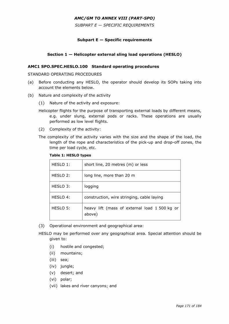
AMC/GM TO ANNEX VIII (PART-SPO)
SUBPART E — SPECIFIC REQUIREMENTS
Page 171 of 184
Subpart E — Specific requirements
Section 1 — Helicopter external sling load operations (HESLO)
AMC1 SPO.SPEC.HESLO.100 Standard operating procedures
STANDARD OPERATING PROCEDURES
(a) Before conducting any HESLO, the operator should develop its SOPs taking into
account the elements below.
(b) Nature and complexity of the activity
(1) Nature of the activity and exposure:
Helicopter flights for the purpose of transporting external loads by different means,
e.g. under slung, external pods or racks. These operations are usually
performed as low level flights.
(2) Complexity of the activity:
The complexity of the activity varies with the size and the shape of the load, the
length of the rope and characteristics of the pick-up and drop-off zones, the
time per load cycle, etc.
Table 1: HESLO types
HESLO 1: short line, 20 metres (m) or less
HESLO 2: long line, more than 20 m
HESLO 3: logging
HESLO 4: construction, wire stringing, cable laying
HESLO 5: heavy lift (mass of external load 1 500 kg or
above)
(3) Operational environment and geographical area:
HESLO may be performed over any geographical area. Special attention should be
given to:
(i) hostile and congested;
(ii) mountains;
(iii) sea;
(iv) jungle;
(v) desert; and
(vi) polar;
(vii) lakes and river canyons; and

AMC/GM TO ANNEX VIII (PART-SPO)
SUBPART E — SPECIFIC REQUIREMENTS
Page 172 of 184
(viii) environmentally sensitive areas (e.g. national parks, noise sensitive
areas).
(c) Equipment
(1) The helicopter may be equipped with:
(i) additional mirror(s);
(ii) a bubble window;
(iii) supplementary hook(s) or multi-hook device(s); and
(iv) load data recorder (lifts, weights, torques, power, forces, shocks and
electrical activities).
(2) Non-assisted vertical reference operations may require additional engine
monitoring in the pilot line of vision or an audio warning system.
(3) All additional equipment used, e.g. ropes, cables, mechanical hooks, swivel
hooks, nets, buckets, chainsaws, baskets, containers, should be
manufactured according to applicable rules or recognised standards. The
operator should be responsible for maintaining the serviceability of this
equipment.
(4) Adequate radio communication equipment (e.g. VHF, UHF, FM) should be
installed and serviceable in the helicopter for co-ordination with the task
specialists involved in the operation.
(5) Task specialists involved in the operation should be equipped with hand-held
communication equipment, protective helmets with integrated earphones and
microphones.
(d) Crew members
(1) Crew composition:
(i) The minimum flight crew as stated in the approved AFM. For operational
or training purposes, an additional crew member may assist the pilot-in-
command (PIC) in a single-pilot operation.
(ii) For safety and/or operational purposes, task specialists should be
instructed by the operator to fulfil specified tasks (e.g. to establish
vertical reference).
(2) Pilot initial training
Before acting as PIC, the pilot should demonstrate to the operator that
he/she has the required skills and knowledge.
(i) Theoretical knowledge:
(A) content of the operations manual (OM) including the relevant
SOP;
(B) AFM (limitations, emergencies, etc.);
(C) procedures for certain operations (short line, long line,
construction, wire stringing or cable laying flying techniques, as
required for the operation);
AMC/GM TO ANNEX VIII (PART-SPO)
SUBPART E — SPECIFIC REQUIREMENTS
Page 173 of 184
(D) load and site preparation including load rigging techniques and
external load procedures;
(E) special equipment used in the operation;
(F) training in human factor principles; and
(G) hazards and dangers.
(3) Pilot experience
(i) For operations with a maximum external load mass of less than
1 500 kg, the PIC should have at least the following experience:
Prior to commencing training:
(A) 300 hours helicopter flight experience as PIC, which should be
increased to 500 hours experience as PIC for mountain
operations; and
(B) 10 hours flight experience on the helicopter type;
Before acting as PIC:
(C) 30 hours on the helicopter type, performing HESLO 1 and 2
operations. Where a pilot has accomplished 50 hours in HESLO 1
and 2 operations, the 30 hours experience on the helicopter type
may be reduced to 15 hours.
(ii) For operations with a maximum external load mass of 1 500 kg and
above, the pilot-in-command should have at least the following
experience:
Prior to commencing training:
(A) 1 000 hours helicopter flight experience as PIC, which should be
increased to 1 500 hours experience as PIC for mountain
operations ;
(B) 10 hours flight experience on the helicopter type;
Before acting as PIC:
(C) 30 hours on the helicopter type, performing HESLO 1 and 2
operations. Where a pilot has accomplished 50 hours in HESLO 1
and 2 operations, the 30 hours experience on the helicopter type
may be reduced to 15 hours.
(D) At least 20 hours gained in an operational environment similar to
environment of intended operation (desert, sea, jungle, etc.).
(iii) For HESLO 3 only, additionally to experience (i) or (ii):
Prior to commencing training:
(A) At least qualified as PIC for HESLO 1 type;
(B) Minimum 500 HESLO cycles.
(iv) For HESLO 4 only, additionally to (i) or (ii):
Prior to commencing training:
AMC/GM TO ANNEX VIII (PART-SPO)
SUBPART E — SPECIFIC REQUIREMENTS
Page 174 of 184
(A) At least qualified as PIC for HESLO 2 or HESLO 3;
(B) Minimum 1000 flight hours on helicopters; and
(C) Minimum 3000 HESLO cycles.
(4) Pilot recurrent training and checking at least every two years:
(i) review of the load rigging techniques;
(ii) external load procedures;
(iii) review of the applicable flying techniques; and
(iv) review of human factor principles.
(v) A pilot who has performed 20 hours of relevant HESLO within the past
12 months may not need any further flight training other than in
accordance with Part-FCL.
(e) Task specialists
Before acting as task specialist, he/she should demonstrate to the operator that
he/she has been trained appropriately and has the required skill and knowledge.
(1) Initial training
(i) The initial training of task specialists should include at least:
(A) behaviour in a rotor turning environment and training in ground
safety and emergency procedures;
(B) procedures including load rigging, usage and conservation
(replacement) of LLD;
(C) helicopter marshalling signals;
(D) radio communication;
(E) selection and preparation of pick-up and drop-off sites, dangers on
working places (downwash, loose goods, third people);
(F) handling and safety of third party;
(G) relevant training for the helicopter type;
(H) duties and responsibilities as described in the appropriate manual;
(I) perception and classification of flight obstacles (none, critical,
danger), measures for safety; and
(J) human factor principles.
(ii) The individual safety equipment appropriate to the operational
environment and complexity of the activity should be described in the
appropriate manual.
(2) Recurrent training
(i) The annual recurrent training should include the items listed in the
initial training as described in (e)(1) above.
(ii) The operator should establish a formal qualification list for each
individual task specialist.
AMC/GM TO ANNEX VIII (PART-SPO)
SUBPART E — SPECIFIC REQUIREMENTS
Page 175 of 184
(iii) The operator should establish a system of record keeping that allows
adequate storage and reliable traceability of:
(A) the initial and recurrent training;
(B) Qualifications (qualification list).
(3) Briefing of task specialists
Briefings on the organisation and coordination between flight crew and task
specialists involved in the operation should take place prior to each operation.
These briefings should include at least the following:
(i) location and size of pick-up and drop-off site, operating altitude;
(ii) location of refuelling site and procedures to be applied; and
(iii) load sequence, danger areas, performance and limitations, emergency
procedures.
(4) Responsibility of task specialists operating on the ground:
(i) Task specialists operating on the ground are responsible for the safe
organisation of the ground operation, including:
(A) adequate selection and preparation of the pick-up and drop-off
points and load rigging;
(B) appropriate communication and assistance to the flight crew and
other task specialists; and
(C) access restriction on the pick-up and drop-off site.
(ii) If more than one task specialist is required for a task, one should be
nominated as leading the activities. He/she should act as main link
between flight crew and other task specialist(s) involved in the
operation and is responsible for:
(A) task specialist co-ordination and activities on the ground; and
(B) the safety of the working area (loading and fuelling).
(f) HESLO instructor
The HESLO instructor should be assigned by the operator on the basis of the
following:
(1) the HESLO instructor for pilots should be suitably qualified as determined by
the operator and have a minimum experience of 500 hours HESLO operations
in the appropriate HESLO level on which instruction is to be provided as well
as experience in instructing according to the flight instructor or type rating
instructor training;
(2) the HESLO instructor for task specialists should be suitably qualified as
determined by the operator and have at least 2 years of experience in HESLO
operations.
(g) Performance
(1) Power margins for HESLO operations:
(i) HESLO 1 and 2
AMC/GM TO ANNEX VIII (PART-SPO)
SUBPART E — SPECIFIC REQUIREMENTS
Page 176 of 184
The mass of the helicopter should not exceed the maximum mass
specified in accordance with SPO.POL.146(c)(1) at the pick-up or drop-
off site, whichever is higher, as stated in the appropriate manual.
(ii) HESLO 3, 4 and 5
The mass of the helicopter should not exceed the maximum mass
specified in accordance with SPO.POL.146(c)(1) at the pick-up or drop-
off site, whichever is higher, as stated in the appropriate manual, and in
case of construction (montage) operations, reduced by 10% of the
mass of the sling load capacity.
(h) Normal procedures
(1) Operating procedures:
HESLO should be performed in accordance with the appropriate manual and
appropriate operating procedures. These procedures should include, for each
type of operation:
(i) crew individual safety equipment (e.g. helmet, fire retardant suits);
(ii) crew responsibilities;
(iii) crew coordination and communication;
(iv) selection and size of pick-up and drop-off sites;
(v) selection of flight routes;
(vi) fuel management in the air and on the ground;
(vii) task management; and
(viii) third party risk management.
(2) Ground procedures:
The operator should specify appropriate procedures, including:
(i) use of ground equipment;
(ii) load rigging;
(iii) size and weight assessment of loads;
(iv) attachment of suitably prepared loads to the helicopter;
(v) two-way radio communication procedures;
(vi) selection of suitable pick-up and drop-off sites;
(vii) safety instructions for task specialists operating on the ground;
(viii) helicopter performances information;
(ix) fuel management on the ground;
(x) responsibility, organisation and task management of other personnel on
the ground involved in the operation;
(xi) third party risk management; and
(xii) environmental protection.
(i) Emergency procedures
(1) Operating procedures for the flight crew:
In addition to the emergency procedures published in the AFM or OM, the operator
should ensure that the flight crew:
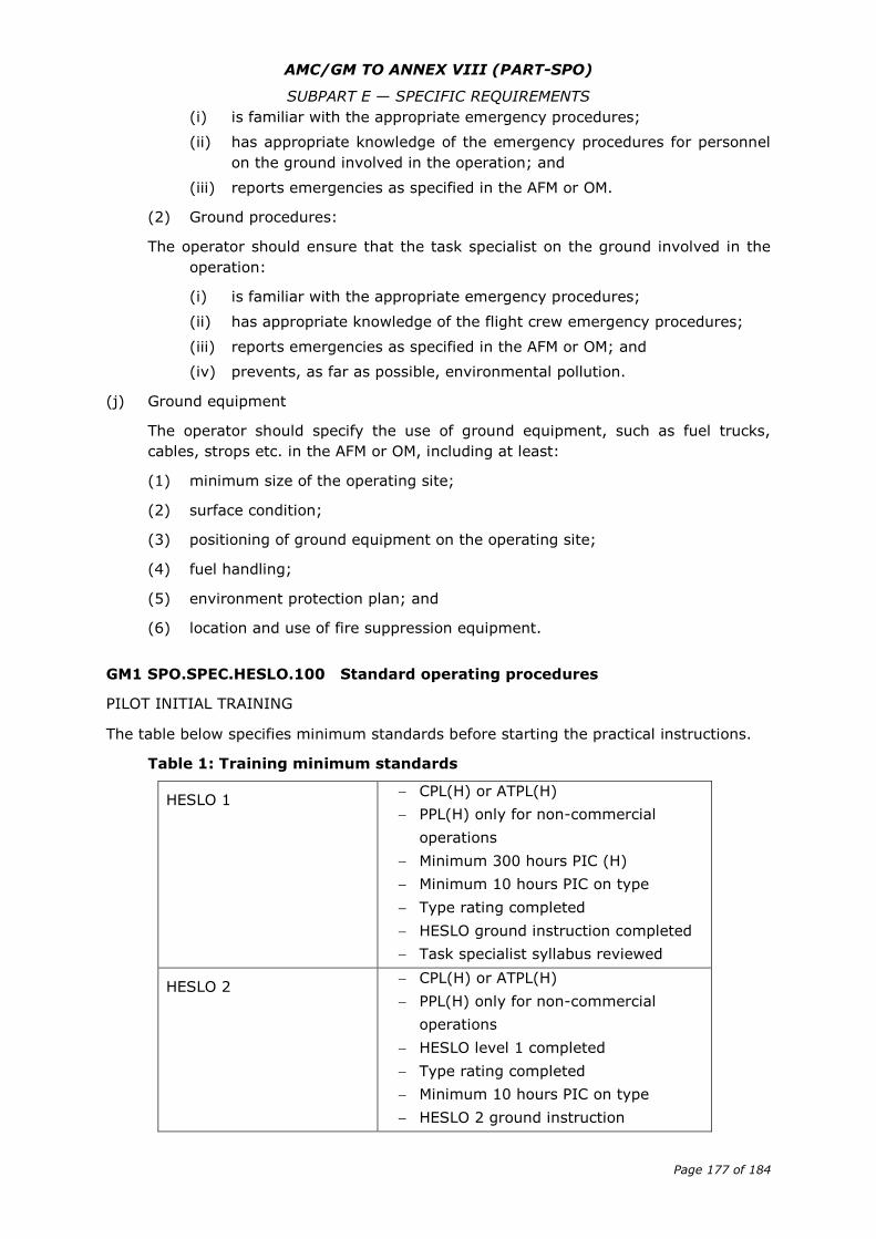
AMC/GM TO ANNEX VIII (PART-SPO)
SUBPART E — SPECIFIC REQUIREMENTS
Page 177 of 184
(i) is familiar with the appropriate emergency procedures;
(ii) has appropriate knowledge of the emergency procedures for personnel
on the ground involved in the operation; and
(iii) reports emergencies as specified in the AFM or OM.
(2) Ground procedures:
The operator should ensure that the task specialist on the ground involved in the
operation:
(i) is familiar with the appropriate emergency procedures;
(ii) has appropriate knowledge of the flight crew emergency procedures;
(iii) reports emergencies as specified in the AFM or OM; and
(iv) prevents, as far as possible, environmental pollution.
(j) Ground equipment
The operator should specify the use of ground equipment, such as fuel trucks,
cables, strops etc. in the AFM or OM, including at least:
(1) minimum size of the operating site;
(2) surface condition;
(3) positioning of ground equipment on the operating site;
(4) fuel handling;
(5) environment protection plan; and
(6) location and use of fire suppression equipment.
GM1 SPO.SPEC.HESLO.100 Standard operating procedures
PILOT INITIAL TRAINING
The table below specifies minimum standards before starting the practical instructions.
Table 1: Training minimum standards
HESLO 1 CPL(H) or ATPL(H)
PPL(H) only for non-commercial
operations
Minimum 300 hours PIC (H)
Minimum 10 hours PIC on type
Type rating completed
HESLO ground instruction completed
Task specialist syllabus reviewed
HESLO 2 CPL(H) or ATPL(H)
PPL(H) only for non-commercial
operations
HESLO level 1 completed
Type rating completed
Minimum 10 hours PIC on type
HESLO 2 ground instruction
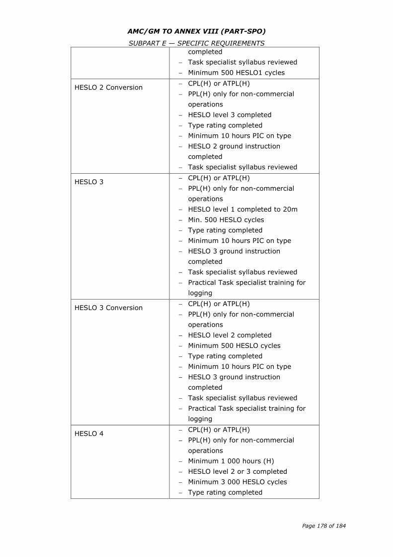
AMC/GM TO ANNEX VIII (PART-SPO)
SUBPART E — SPECIFIC REQUIREMENTS
Page 178 of 184
completed
Task specialist syllabus reviewed
Minimum 500 HESLO1 cycles
HESLO 2 Conversion CPL(H) or ATPL(H)
PPL(H) only for non-commercial
operations
HESLO level 3 completed
Type rating completed
Minimum 10 hours PIC on type
HESLO 2 ground instruction
completed
Task specialist syllabus reviewed
HESLO 3 CPL(H) or ATPL(H)
PPL(H) only for non-commercial
operations
HESLO level 1 completed to 20m
Min. 500 HESLO cycles
Type rating completed
Minimum 10 hours PIC on type
HESLO 3 ground instruction
completed
Task specialist syllabus reviewed
Practical Task specialist training for
logging
HESLO 3 Conversion CPL(H) or ATPL(H)
PPL(H) only for non-commercial
operations
HESLO level 2 completed
Minimum 500 HESLO cycles
Type rating completed
Minimum 10 hours PIC on type
HESLO 3 ground instruction
completed
Task specialist syllabus reviewed
Practical Task specialist training for
logging
HESLO 4 CPL(H) or ATPL(H)
PPL(H) only for non-commercial
operations
Minimum 1 000 hours (H)
HESLO level 2 or 3 completed
Minimum 3 000 HESLO cycles
Type rating completed
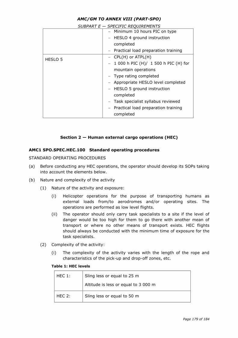
AMC/GM TO ANNEX VIII (PART-SPO)
SUBPART E — SPECIFIC REQUIREMENTS
Page 179 of 184
Minimum 10 hours PIC on type
HESLO 4 ground instruction
completed
Practical load preparation training
HESLO 5 CPL(H) or ATPL(H)
1 000 h PIC (H)/ 1 500 h PIC (H) for
mountain operations
Type rating completed
Appropriate HESLO level completed
HESLO 5 ground instruction
completed
Task specialist syllabus reviewed
Practical load preparation training
completed
Section 2 — Human external cargo operations (HEC)
AMC1 SPO.SPEC.HEC.100 Standard operating procedures
STANDARD OPERATING PROCEDURES
(a) Before conducting any HEC operations, the operator should develop its SOPs taking
into account the elements below.
(b) Nature and complexity of the activity
(1) Nature of the activity and exposure:
(i) Helicopter operations for the purpose of transporting humans as
external loads from/to aerodromes and/or operating sites. The
operations are performed as low level flights.
(ii) The operator should only carry task specialists to a site if the level of
danger would be too high for them to go there with another mean of
transport or where no other means of transport exists. HEC flights
should always be conducted with the minimum time of exposure for the
task specialists.
(2) Complexity of the activity:
(i) The complexity of the activity varies with the length of the rope and
characteristics of the pick-up and drop-off zones, etc.
Table 1: HEC levels
HEC 1: Sling less or equal to 25 m
Altitude is less or equal to 3 000 m
HEC 2: Sling less or equal to 50 m
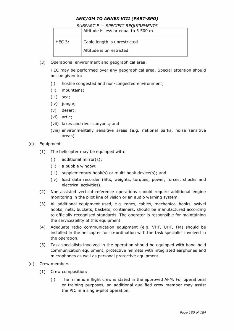
AMC/GM TO ANNEX VIII (PART-SPO)
SUBPART E — SPECIFIC REQUIREMENTS
Page 180 of 184
Altitude is less or equal to 3 500 m
HEC 3: Cable length is unrestricted
Altitude is unrestricted
(3) Operational environment and geographical area:
HEC may be performed over any geographical area. Special attention should
not be given to:
(i) hostile congested and non-congested environment;
(ii) mountains;
(iii) sea;
(iv) jungle;
(v) desert;
(vi) artic;
(vii) lakes and river canyons; and
(viii) environmentally sensitive areas (e.g. national parks, noise sensitive
areas).
(c) Equipment
(1) The helicopter may be equipped with:
(i) additional mirror(s);
(ii) a bubble window;
(iii) supplementary hook(s) or multi-hook device(s); and
(iv) load data recorder (lifts, weights, torques, power, forces, shocks and
electrical activities).
(2) Non-assisted vertical reference operations should require additional engine
monitoring in the pilot line of vision or an audio warning system.
(3) All additional equipment used, e.g. ropes, cables, mechanical hooks, swivel
hooks, nets, buckets, baskets, containers, should be manufactured according
to officially recognised standards. The operator is responsible for maintaining
the serviceability of this equipment.
(4) Adequate radio communication equipment (e.g. VHF, UHF, FM) should be
installed in the helicopter for co-ordination with the task specialist involved in
the operation.
(5) Task specialists involved in the operation should be equipped with hand-held
communication equipment, protective helmets with integrated earphones and
microphones as well as personal protective equipment.
(d) Crew members
(1) Crew composition:
(i) The minimum flight crew is stated in the approved AFM. For operational
or training purposes, an additional qualified crew member may assist
the PIC in a single-pilot operation.
AMC/GM TO ANNEX VIII (PART-SPO)
SUBPART E — SPECIFIC REQUIREMENTS
Page 181 of 184
(ii) For safety and/or operational purposes, a task specialist may be
required by the operator to fulfil the task (e.g. to establish vertical
reference or to operate the release safety device for the belly rope).
(2) Pilot initial training:
Before acting as PIC, the pilot should demonstrate to the operator that
he/she has the required skills and knowledge, as follows:
(i) Theoretical knowledge:
(A) load rigging techniques;
(B) external load procedures;
(C) site organisation and safety measures;
(D) short line, long line, construction, wire stringing or cable laying
flying techniques, as required for the operation.
(ii) Pilot experience prior to commencing the training:
(A) 1 000 hours helicopter flight experience as PIC, of which 500h
should be gained in mountainous areas for training in mountain
operations;
(B) 10 hours flight experience on the helicopter type;
(C) type rating completed;
(D) HESLO type 1 or 2 completed;
(E) relevant experience in the field of operation;
(G) training in human factor principles; and
(F) ground instruction completed (marshaller syllabus).
(3) Pilot recurrent training and checking at least every two years:
(i) review of the sling technique;
(ii) external load procedures;
(iii) training in human factor principles; and
(iii) review of the applicable flying techniques.
(4) Conditions of HEC instruction:
(i) Maximum sling length according to the level applicable:
(A) 1 task specialist (with radio) at pickup point;
(B) 1 task specialist (with radio) at drop off point/on the line;
(C) helicopter fitted with cargo mirror/bubble window;
(D) flight instruction DC/: Cycles DC/minimum 10 cycles which of 5
Human Cargo Sling; and
(E) flight instruction solo with onsite supervision/Cycles solo/minimum
10 cycles.
(ii) HEC instructor:
AMC/GM TO ANNEX VIII (PART-SPO)
SUBPART E — SPECIFIC REQUIREMENTS
Page 182 of 184
The HEC instructor should be assigned by the operator on the basis of
the following:
(A) the HEC instructor for pilots should hold or have held flight
instructor rating and should have a minimum experience of
100 cycles in HEC operations in the appropriate HEC level on
which instruction is to be provided;
(B) the HEC instructor for task specialists should be suitably qualified
as determined by the operator and have at least 2 years of
experience in HEC operations as a task specialist.
(e) Task specialists
Before acting as task specialists, they should demonstrate to the operator that they
have been appropriately trained and have the required skills and knowledge
including training on human factor principles.
(1) Task specialists should be trained to operate the system including:
(i) montage and removal of system; and
(ii) normal procedure.
(2) Briefings
Briefings on the organisation and coordination between flight crew and task
specialist involved in the operation should take place prior to each operation.
These briefings should include at least the following:
(i) location and size of pick-up and drop-off site, operating altitude;
(ii) location of refuelling site and procedures to be applied; and
(iii) load sequence, danger areas, performance and limitations, emergency
procedures.
(3) Recurrent training
(i) The annual recurrent training should include the items listed in the
initial training as described in (e)(1) above.
(ii) The operator should establish a formal qualification list for each
individual task specialist.
(iii) The operator should establish a system of record keeping that allows
adequate storage and reliable traceability of:
(A) the initial and recurrent training;
(B) qualifications (qualification list).
(f) Performance
HEC should be performed with the following power margins: the mass of the
helicopter should not exceed the maximum mass specified in accordance with
SPO.POL.146(c)(1).
(g) Normal procedures
(1) Operating procedures:
HEC should be performed in accordance with the AFM. Operating procedures
should include, for each type of operation:
AMC/GM TO ANNEX VIII (PART-SPO)
SUBPART E — SPECIFIC REQUIREMENTS
Page 183 of 184
(i) crew individual safety equipment (e.g. helmet, fire retardant suits);
(ii) crew responsibilities;
(iii) crew coordination and communication;
(iv) selection and size of pick-up and drop-off sites;
(v) selection of flight routes;
(vi) fuel management in the air and on the ground;
(vii) task management; and
(viii) third party risk management.
(2) Ground procedures:
The operator should specify appropriate procedures, including:
(i) use of ground equipment;
(ii) load rigging;
(iii) size and weight assessment of loads;
(iv) attachment of suitably prepared loads to the helicopter;
(v) two-way radio communication procedures;
(vi) selection of suitable pick-up and drop-off sites;
(vii) safety instructions for ground task specialists or other persons required
for the safe conduct of the operation;
(viii) helicopter performances information;
(ix) fuel management on the ground;
(x) responsibility and organisation of the personnel on the ground involved
in the operation;
(xi) task management of personnel on the ground involved in the operation;
(xii) third party risk management; and
(xiii) environmental protection.
(h) Emergency procedures
(1) Operating procedures:
In addition to the emergency procedures published in the AFM or OM, the
operator should ensure that the flight crew:
(i) is familiar with the appropriate emergency procedures;
(ii) has appropriate knowledge of the emergency procedures for personnel
on the ground involved in the operation; and
(iii) reports emergencies as specified in the AFM or OM.
(2) Ground procedures:
The operator should ensure that the task specialist on the ground involved in
the operation:
(i) is familiar with the appropriate emergency procedures;
(ii) has appropriate knowledge of the emergency procedures for personnel
on the ground involved in the operation;
(iii) reports emergencies as specified in the AFM or OM; and
AMC/GM TO ANNEX VIII (PART-SPO)
SUBPART E — SPECIFIC REQUIREMENTS
Page 184 of 184
(iv) prevents, as far as possible, environmental pollution.
AMC1 SPO.SPEC.HEC.105(b) Specific HEC equipment
AIRWORTHINESS APPROVAL FOR HEC EQUIPMENT
(a) Hoist or cargo hook installations that have been certificated according to any of the
following standards should be considered to satisfy the airworthiness criteria for
HEC operations:
(1) CS 27.865 or CS 29.865;
(2) JAR 27 Amendment 2 (27.865) or JAR 29 Amendment 2 (29.865) or later;
(3) FAR 27 Amendment 36 (27.865) or later — including compliance with CS
27.865(c)(6); or
(4) FAR 29 Amendment 43 (29.865) or later.
(b) Hoist or cargo hook installations that have been certified prior to the issuance of
the airworthiness criteria for HEC as defined in (a) may be considered as eligible
for HEC provided that following a risk assessment either:
(1) the service history of the hoist or cargo hook installation is found satisfactory
to the competent authority; or
(2) for hoist or cargo hook installations with an unsatisfactory service history,
additional substantiation to allow acceptance by the competent authority
should be provided by the hoist or cargo hook installation certificate holder
(type certificate (TC) or supplemental type certificate (STC)) on the basis of
the following requirements:
(i) The hoist or cargo hook installation should withstand a force equal to a
limit static load factor of 3.5, or some lower load factor, not less than
2.5, demonstrated to be the maximum load factor expected during hoist
operations, multiplied by the maximum authorised external load.
(ii) The reliability of the primary and back up quick release systems at
helicopter level should be established and failure mode and effect
analysis at equipment level should be available. The assessment of the
design of the primary and back up quick release systems should
consider any failure that could be induced by a failure mode of any
other electrical or mechanical rotorcraft system.
(iii) The appropriate manual should contain one-engine-inoperative (OEI)
hover performance data or single engine failures procedures for the
weights, altitudes, and temperatures throughout the flight envelope for
which hoist or cargo hook operations are accepted.
(iv) Information concerning the inspection intervals and retirement life of
the hoist or cargo hook cable should be provided in the instructions for
continued airworthiness.