accelerations in flight’ - digital library/67531/metadc65749/m...accelerations in flight’ by l?....
TRANSCRIPT

ACCELERATIONS IN FLIGHT’
By l?. H. NORTON and E. T. ALLEN
Langley Memorial Aeronautical LaboratoryXationaI Advisory Committee for Aeronautics
Langley Field, T7a.
So~E.—Thie report waeprepmd for the BurexJ of (constructionand Repti, Navy Department,and is published by permimionof the Chief Constructor,U. S. Navy
481

.
*
.

REPORT’ No. 99.
ACCELEJ3ATIOYW IN FLIGHT.
F. E. Nomox and E. T. ALLEN,National .4dvismy (lommittee for Aeronautics.
INTRODUCTION.
This work on accelerometry was carried out ‘at the Langley Field Station of the A’stiondAdvisory Committee for Aeronautics at the request of the Bureau of Construction and Repair,United States X’avy, for the purpose of obtaining the magnitude of the load factors in flightand to procure information on the behavior of an airplane in wwious maneuvers.
When an airplane is fbying on a straight and Ievel course a spring scale with a 1-pouncIweight attached to iti wouId record 1 pound. If, however, the pkme is put into a turn or azoom the scale dl no longer record I pound, but. may record 2 or even 3 pounds—that is, the&pparent weight of objects on the airplane have increased two or three times. Should thecontroI be suddenly pushed forward to nose the plane over, the spring scak may read zero—that is, an object on the plane would have no weight. When a spring sca.Ie is used in this waythe pound graduations on the scale represent accelerations in terms of the acceleration ofgravity g, -which is in English units about 32 feet per second per second-
If the average loadi~~ of the w@s is 10 pounds per square foot in Ievd flight, during amaneuver in which the spring scale reads 3 the wings would then be carrying a Ioad of 30pounck per square foot. The readings of the accelerometer therefore gi-re the Ioads that theairplane structure must undergo during a maneuver- and ako the loztd that. the pilot andpassengers experience. Every Hier knows that. he is pushed down into his seat during a tight
t
spiral, for instance, and it is aImost impossible to stand up or Iift the feet from the Boor. During———
violent stunt-s a 180-pound man ma-y increase in w~~ht to as much as 800 pounds.The accelerometer records are of wdue to the designer, as they show him what stresses
the airpIane structure undergoes and ho-w Iong these stresses last. The records ako showclearIy the piIot’s ability, especially in stunts and in landings, so that an accelerometer shouIdbean excellent meam of examining a flier, as it gives a clear and unbiased record of his handlingof a machine.
>——
I)ESCRD?TION OF INSTRUMENT.
.4s the spring scale and weight described abo~e wouId be undamped and wouId ha_re sucha long period that the shorter tibratio~ w~uld not be recorded, an instrument working cm thesame principIe was bolt.: but having a much tigher period and means for recording the accelera-tions on a moving b. The instrument consists mainly of a flat steel spring supported riggdl~at one end, so that the free end may be deflected by its ovcu weight from its neutral positionby any acceleration acti~~ at right ~ngles to the pIane of the spring. This deflection k meas-ured by a very ~~ht tiIting tier, Camsed to rotate by the deflection of the spring, and thusreflect ing a beam of light onto a KLOT-@ fi, gi~g an zccuracy of about 0.01 g. The essentia~portions of this instrment me sho~ ~ F+. I ~d photographs of it in Figs. 2 ad 3.
The motion of the spring is damped by a thin aIuminum vane, wbieh tibrates ~~ thespring between the poles of an electric mab~et, and the amount of damping can be varied byaltering the current passing through the magnet. The source of light consists of a low=roltagetunggten ]amp -rery skrd~ to a fl~h.@&t b~b, the &age of its filament being focused afterreflection from the mirror onto the no-ring fihm. This fiIm is driven at constant speed by a
48.3

484 A~T~TuAL REPORT ~AT~()~& AD\,I~(JR~ I’Jo~J~’~~E FOR A~R()~AuTIc,$j,
governor-controHcd cIock having an electric brake for starting and stopping at R distancr.In order to determine the constancy of the cIock under accelerations it was mounted on awhirling arm and its rate was measured at several speeds of the whirling arm. In Pig. 4 is
shown a curve of speed variation plotted against acceleration. Itmvill be noticed that tlw
point at zero g is shown considerably above the curve, this being due to the fact that the clockwas tested on its side} giving zero g along the -vertical axis but not along the horizon~al axis,as itshould be to make all parts weightless. By careful design of the governor it shouki bepossibIe to keep the speed of the clock constant within 1 per cent under any acceleration thtwould occur in an airplane. ii photograph of the clock is shown in Fig. 5. The naturaIperiod of the instrument is 70 vi’mations per second, which is high enough to be above anymotor vibrations that could occur, and yet a deflection of ; inch is obtained on the film foran acceleration of I g. In order to give a reference line from which to measure accelerations
a second mirror is fixed in such a way that it reflects a steady beam of light on the film at thvposition of zexo g.
In order to test the performance of the instrument it was mounted on a whirling arm ha-ringa horizontal axis. U“pon rotating the arm the accelerations on the instrument changed througha range of 2 g, f or each revolut ion, thus tracing a sine curve, the height of its medium line clcpPnd-
E\ecfm -mugnef.
Domp/hg vune.Verfjculsi;k
(-’,[ Spr~ng.
PI $4 f=!I
L_/ No vlng m[rror. (o
— ——M7VZ9—LZZG.—- — ‘— ‘–‘._/.
%
. .— —— ————————.——— -——_ -- ~Stofionory beum.— -_ ----
Wuich ho/> sprfhg AdJusfoble — —‘=:>fo holdmkror Qx[e zero m/-rror.
‘-%1/
up uguinsfpoi~fedscrew. ‘b -L !,,!,, Lffmp.
I
IRevo/+Yng7?%77drum.
~’
I~lG,1,
ing on the rate at which the whirling arm was revolved. A record taken in this way is shown inFig. 26. It will be noticed that the cuwe is very smo-oth and with practically no instrumentalvibrations. In order to test the instrument for vibrations of a high pwiod, a rocking platformwas constructed that couId be oscillated at any frequency or amplitude by means of cams,The accelerometer was fastened to the table of this oscillator and a record taken as shown inFig. 28. AS one, cam had a s]ight Iead on the other there was a sharp knock experienced once
every revolution, thus causing excessive vibration in the accelerometer record. Thti instru-ment was then mounted on about l-inch of sponge rubber and another record taken in the sameway, except that the fiIm was run at a slightly greater speed, in order to separate the vibrationsmore clearly. This record is show~ in Fig. 29, and it will be seen that the smaller vibrationsare almost completely dstmped out by the rubber.
After the laboratory tests on the instrument were satisf ac.tori~y completed, it was mountedin the JN4H airplane, on a sponge rubber mounting, which isolated it from the vibrationsof the fuselage. The instrument was mounted in the frorit cockpit and was within a few inchesof the center of gravity of the machine, and two switches were wired back to the pilot so thathe could start the clock or turn on the light at any time. In the other airplanes on which re-cords were takem it was necessary to carry the instrument in the rear cockpit, which is severalfeet behind the center of gravity, so that the accelerations recorded on these machines -were
1

—
\
[
—
I
_—---
—F[G. 5.—AcCELEROMETER cLuLfi.

FIG. 6.—LANDING, JN4H, TAIL HIGH AND LITTLE LEVELING OFF. THE PROPELLER WAS NOT REVOLVING. THE MACHINE
HAD PRACTICALLY STOPPED ROLLING AT END OF THE RECORD. MAXIMUM ACCELERATION IS 5.7-5 G. —.

FIG, 8.–LANDING, JN411, THREE POINT, QUITE
SMOOTH. MAX IMUtVl ACCELERATION lS 2.20 G.
,
FIG. 10. -L AN DIN G, JN4.FI, TAIL HIGH, E!(JT NOT VERY ROIJG~-1, MAXIMUM
ACCELERATION 15 3.14 G.
FIG. 9.—LANDING, DH4.B, SMOOTH. MAXIMUM ACCELERATION IS 2.56 G
FIG. 11.-TAKE OFF, JN41+. FAIRLY SMOOTH GROUND, LAST BOUNCE MADE
PUF’#OSELY, GIVING AN ACCELERATION OF 3,78 G.

FIG. 12,–LOOP, JN4H. AIR SPEED AT START WAS 72 M, P. H. QUICK PULL UP, STALLED AT
THE TOP AND FELL OUT SIDEWAYS. FIRST MAXIMUM IS 3,21 G. AND SECOND IS 2.75 G,
FiG. r3—LOOP, .IN4H. THE AIR sPEED AT START WAS
75 M, P. H., HIJNG AT TOP. FIRST MAXIMUM 1S’2.85
G. AND SECOND IS 3,22 G, ‘
484-4
FIG. 14.–STICK PULLED BACK
AS SUDDENLY AS POSSIBLE
ON THE DH4B AT 75 M, P, H.
MAXIMUM ACCELERATION
IS 2.05 G,

..
ACCELERATIONS IN FLKIE.T. 485
somewhat in errorj due to the effect of an,guIar rotation of the whole machine. The recordsobtained begin at the left hand end of the film and run toward the right, and the film mows atthe rate of 0.215 inch per second, and in au casss an acceleration of 1 g. corresponds to 0.70inch, measured from the zero line. It will be noticed that even -with the shock-absorbing rubberthere is transmitted to the instrument a certain definite period of vibration from the fuselageof the plane, and that the period of this vibration is constant for any plane, no matter what thet~ngine speed, but as the amplitude of this vibration is small it is quite easy to estimate a meanline which VW represent the true accelerations on the machine as a whole. Ml accelerationsare taken normal to the wing chord,
RECORDS OBTAINED IN FLIGHT.
Landings and Wce-ofls.-k Fig. 6 is show--na record of a land@ made in a ~T-4H, with thetail I@h and w-ith littJe or no Ieveling off from the glide, and it will be noticed that the firsitime the wheels struck the ground an acceleration of 5.25 g. was reached, then the machinebounced ido the air for about two seconds, struck again with s~ightly less shock, and thenrebounded twice more, each bounce be~~ of shorter period and each shock of less mamitude,until the machine fiaI& rested permanent.Iyon the ground. It is also etideni that w-hiIetaxiing e~en on a fairly smooth field, accel- 4erations of M much as 2.5 g. are experienced,and a good landi~r will always give less ac- ~3
cderation than will the subsequent taxi-iug ~on anything except the smoothest of fields.
g2In Fig. 7 the same machine was pancaked ~with a drop of abouk 4 feet, giving an accder-- .Qation at the time of striking of 4.95 g. and .~ ‘the rebound was very slight, and altho~~h ~this land~~ was intentionally made with a $ uconsiderable drop it did not feel ro~~her thap $many routine landings. Fig. S is a record of ka smooth tkree-point landing, where the ac- ‘/celebration on first str~m is only 2.2jg.lwhichis considerably less than some of the ac.celer-
96 % /00 /02 /04 /&?& /m
ations eqerienced short.ly aftwwwrds while (%- mf v-./ufi’ .6+dockqzeed.
taxi-ing. - Fig. 9 shows a smooth landi~r in a
DH-4B, the acceleration when &et tout-~FIG.4.-Speed variatim in wcelerometer ciwk under aeceIeratimr.
behg onI-y 2.56g.,representing an average landing f or this type of machine. In Fig. 10 is showna tail-~~h landing in a mT-.lH, when the macfie porpoised considerably, and three -well-markedbounces are evidenk in the record. The maximum acceleration was 3.14 g. and the landing didnot seem exceptionally heavy. F&. I I shows a take-off in a ~~-4H o~er fairly smooth ~o~d,and the Jast bounce was purposely made, which ga~e an acceleration of 3.78 g. It is qtitenoticeable that the vibrations of the plane when the motor is wide open on a climb are of greateramplitude, but of the same period, than when the machine is gliding.
_Looping.-Fig. 12 shows a slow loop tith a JN–4H k which the machine fell out at thetop, a SIOWloop usuaIly being characterized by sharp peaks in the acceleration cume. Fig.13 is another slow loop -where the machine hung at the top, but the mwximum acceleration onpulling out reached 3.22 g., due to a rather long di-re at the end. Fig. 15 shows a loop startedat 100 miles per hour, the mache being pu~ed Up SJOWlyand going over very smoothly, andthe record approaches very nearly a she cuve except for the smaH irregula.rities in the lastend of the record, which are believed tO be due tO the machine entering its own wake, as this factis often noticed in vertical banks as -well as loops. Even with the high initial speed the maxi-mum acceleration was only 3 g. in this Ioop. Fig. 16 is another Ioop takep at 92 miles an hour.Ficr. 17 is a loop made at 105 fi]es au how and shows ~ very smooth record, aIthough the
.
.—

486 Al?lWAL REPORTNATIO~AL ADVISORYCO.%llITT~E FOR A17RO~AUTIU3,
machine was.pulled around rather rapidly and a maximum acccler~tion of 3.6S g. was reached.The length of time taken to complete a loop in a JN--4H ~-w-ied bet~veem 14 and 17 seconds,depending not.so much on the air speecl as on the rate at which the machine was pulled around.
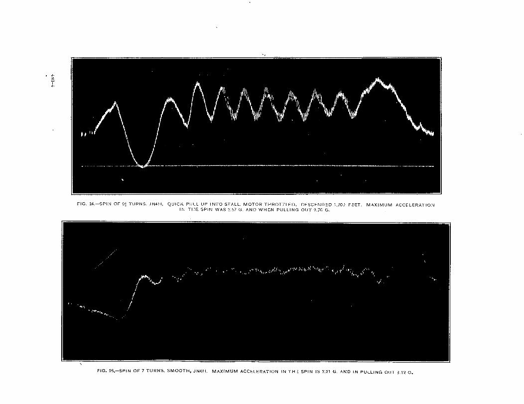
Spi7W-Fig. 24 is ~ spin in a JN–+H, which was stalled into ii suddenly in order to set. upthe maximum amount of oscillation. These oscillations evidently tend t,o damp OULanfl jfthe spin was continued long enough WOUIC1probab~y clisappear. At the beginning of tile recordthe acceleration droppe(l below Og. as the machine fell off from the stall, and after the rccorfl thatfollows very closely a sine cum-e, but the period of the oscillation is nut dependent on the rateof spinning-thak is, one oscillation does not necessarily come in one turn of the spin. Anotherspin on the same machine is shown in Fig. 25,which was a much smoother spin, but t.hc dampe(Ioscillations we still e~ident and an acceleration of 3.12 g. was experienced in pulling’ out ofthis spin. The oscillations me prar.t ically absent in the spin in a. DI-I-~B (’Fig. 22), dampingout after the firsb oscillation. In the same way (Fig. 23) in a recorcl taken of a Bristol fighterthere appears to be only one osci~lation, and after that-the curve is quite smooth and con-tinuous. These recorcis show that there are no large accelerations experienced in the spinitself and unless the machine is di-red rapidly in pulling out accelerations should never Pxceed3 g. on any type of machine in this maneuver.
TigLtNpirtik.-ilrecord of a tight spiral is shown in Fig. 21, giving an acceleration of2.06 g. The accelerations experienced in a tight spiral seem to the pilot greater than theyreally are because the acceleration is conti~uous rather than lasting only a few seconds, as inother maneuvers.
RoZZs.—In Figs. It? and 19 is shown the record of a roll of the JN4H with the rnoiorthrottled and with the motor on. The acceleration rises ~ery rapidly to a shmp peak, thenfalls to about 1 g. and again rises more slowly to a lower peak. The acceleration in the firstpeak is ~ery high, reaching a value of 4.20 g., which is the highest acceleration experiencedin any maneuver. It would seem that rolling would place an exceedingly high stress onthe machine. Strange as it may seem the roll is executed with the rudder, and no aileron kused, so that, it is hard to say at just what parfi of the maneuver the maximum ac.celemtirmcomes, buh it is beliewd to take place after about 90° of roll. The time for a complete rollon this machine was about 11 seconds.
Top Loadir/g,-In Fig. 20 is shown a record where the stick was pushed for~vard as rapicllyas possible at 70 miles an hour, giving an acceleration of – 0.53g. This maneuver is a veryuncomfortable one but it does not seem to place much load on the plane.
SUMMARY OF RECORDS.
The following table gives the maximum acceleration found jn each maneuver:—. .
1 , I! Maneuver. I I Maximum !Machine. acceleration.I1i———— ..-. —- . . i-
1Porpoiselanding. . . . . . . . . . . . . . . . . . . . JN%H............. ! 5.25g.I
Pancake, 4-footdrop. . . . . . . . . . . . . . . . JN-4H- . . . . . . . . . . ..~ 4.95g. I. . . . . . . . . . . . . . . . . . . . . . . . . . . !JhT4H- . . . . . . . . . . ..j3.68g. ~i $? . . . . . . . . . . . . . . . . . . . . . . . . . . . . . . . JN4H . . . . . . . . . . . .. I 4.20g. cI $2 maximum in pulIing out . . . . . . ~~H-- . . . . . . . . . ..i 3.12g.
. . . . . . . . . . . . . . . . . . . . . . . . . . . . . . . DH4B . . . . . ..- . . . ..2.78g. ~
IDo. . . . . . . . . . . . . . . . . . . . . . . . . . . . Brktal. . . .._.....2.72g. i
— ——— — —.
From these figures it would seem that in no reasonable stunt would the air load ever exceed4.5 g. A normal landing shouId not gi-re more than 3 g., and a ver-y rough landing will seldomexceed 5.5 g. It is quite possible that on a high-speed scout machine, higher loadings thanthese would be experienced in stunting, but the acce~erometer records taken by the Bristolin mock fights show no loads in excess of 4.5 g. An attempt was made to obtain records on anS. E. 5, but the present instrument was so bulky that it had to be sttached to the outside of

FIG. 15.—LOOP, JN4H. AIR SPEED AT START lCKl M. P. H. SLOW, SMOOTH PULL UP
NOT ICEAELE BUMP WHEN PULLING OUT, DUE Tc3 ENTER[NG OWN WAKE. F[RST
MAX[MUM IS 3.03 G. AND SECOND IS ?..88 G.
FIG 16.—LOOP, JN4H. A[R SPEED AT START 92 M. P. H.
SMOOTH ALL THE WAY AROUND. FIRST MAXIMUM IS
2.f15 G. AND SECOND IS 2.97 G.
4Si3-I
FIG. 17.—LOOP, JN4H. Al R SPEED AT START WAS 105
M. P. H. SLOW PULL QP. FIRST MAX[MUM [S 3.68G.
AND THE SECOND IS 3.26 G.
.

FIG, 18.–ROLL TO LEFT, MOTOR THROTTLED IN JN4H. MAXIMUM
ACCELERATION IS 4.20 G., THE HIGHEST FOUND IN ANY MANEUVER.
AIR SPEED AT BEG IN NING’WAS 100 M. P. H.
FIG. 20, —TOPLOADING JN4H, STICKPUSHED
FORWARD AS QUICKLY AS POSSIBLE AT
70 M. P. H. MAXIMUM NEGATIVE ACCEL-
ERATION IS -0,53 G.
FIG. 19.–ROLL IN JN4H, TO THE LEFT. MOTOR ON. MAXIMUM
ACCELERATION IS 4.i5 G. AIR SPEED AT BEGINNING WAS
100 M. P. H.
486-2
.

FIG, 21.–TIGHT SPIRAL, MOTOR ON JN41-I. MAXIMUM Acceleration IS 20~ G.
AI,
FIG. 22.-SPIN, DI1413, SMOOTH. MAXIMUM ACCELERATION IS 2,78 G, AS
THE SPIN WAS A LONG ONE, TI-IE FILM WAS STOPPED FOR A SHORT
TIME IN THE MIDDLE OF THE SPIN.
r-IG. 23.—SPIN, BRISTo L FIGHTER (EN G.) ~oTo RT1-l RoTTLEDs THE MAcl-llNE
CAME OUT CIF THE SPIN ITSELF. MAXIMUM ACCELERATION IS 2.72 G.
.
. .
FIG. 24.—SPIN OF 9j TURNS, JN4H. QU[CK PULL UP INTO STALL, MOTOR THROTTLED. DESCENDED 1,701 FEET. MAXIMUM ACCELERATIONIN THE SPIN WAS 2.57 G, AND WHEN PULLING oUT 2.70 G.
FIG. 25.—$PIN OF 7 TURNS, SMOOTH, JN4H. MAXIMUM ACCELERATION IN Tl+i SPIN IS 2.21 G AND IN PULLING OUT 3.12 G.

FIG. 26.—ACCELERATIONS ON WHIRLING ARM.
FIG. 28.—ACCELERATIONS ON ROCKING
TABLE WITK NO RUBBER.
s

FIG. 30, —STFCK PULLED BACK SUDDENLY AT 80
M. P.H. ON JN4H. MOTOR THROTTLED. MAXIMUM
ACCELERATION IS 3.52 G.
FIG. 31.—STICK PULLED BACK SUDDENLY AT 70 M, P. H.
ON JN4H, MOTOR THROTTLED. MAXIMUM ACCELER-
ATION IS 2,76 G.
FIG. 32.—STICK PULLED BACK SUDDENLY AT 60 M, P. H.
ON JN4H. MOTOR THROTTLED. MAX[MUM ACCELERA-
TION IS 2.01 G.
486-6
FIG. 33.–STICK PULLED BACK SUDDENLY AT 50
M. P. H. ON JN4H. MOTOR THROTTLED. MAXI
MUM ACCELERATION IS 1.46 G.

ACC=ERATIOXS IN’ EQGHT. 487
the fuseIage, and although it was partly protected from the propelIer bIast, the titrations setup were so great .ss to obscure the record. ii much smaller instrument of the same type is now
beiwg constructed tmd it is hoped to get records on a macbe of this type in the near future.
ACCELERATIONS LY PULLING OUT OF A DIVE.
In I?igs. 30 to 33 are shown the records obtained when pulling back as suddenly as possibleon the sticIi of a JhT--4H at 50, 60, 70, anc~ 80 miles per hour. The records show that the sametime eIapses for reac~r the masimum acceleration regarcUess of the speed of the plane, andthat this maximum is reached approximately 0.S5 second after the stick is pulled back..+wceIerations obtained from these records are plotted in Fig. 34 against the air speed of thep[ane, and to check them up a second set of runs were taken under the same conditions andtheir values pIotted on the same curve, and the coincidence of the points is exceIIent.. On thesame sheet is also z cume of theoretical accelerations that -wouId be experienced if the planewas imt.ant]y turned to its angle of maximum Iift without los~~ any speed. This theoreticalcurve, as wouId b,e expected, Liessl&htlyabove the experimental curve, but thedifference between the cm-we is muchless than would be supposed, so that thestresses determined from theoreticalcom~iderations should give very closelythe true accelerations when the controlsare suddenly pulled back at any speed.By extending the experimental cur~e tohigher speeds, which can certaidy bedone with very Little error, ib is possibleto estimate the exaeb loading experi-enced in pulling cut of a dive at an~speed. It was not thought advkable tocarry the experiment al points up to anyhigher speeds with the machine at handa]tho~~h it probably wouId ha~e stooda load@ L=high as S.
.4 simiIar set of readings was take~in a DH–4B and one record is shownin Fig. 14, but as it was neees.s~to pIace the instrument, at a consid-erable dist ante behind the center of
A[i ~dh m//es.aerAcwr.
FIG. 34.—.\ceeIerations obtzined b~ .mdderdy pulling mt of a dive (motorfbmttled).
gratity there was a considerable negative acceleration at the instant of pulling back the stickdue to the angular acceleration of the whole machine. For this reason it is probabIe that themaximum accekration obtained is not correct. ,’The points, however, are plotted in Fig. 34along with the theoretic al_Iydetermined curve, and the points lie slightIy above the theoreticalcurve instead of below ifi as they shouId. This may be due to a wrong estimate of the minimumspeed of the plane, as no careful performance tests have been made with this plane as they havewith the ~–1~, or it may be due to an error caused by the angu~ar acceleration of the machine.-kt any rate these teds seem to show eonclwiv~-y that the Ioads determined in pulling out ofa dive at any speed, from the assumption that the machine is iMtmtIy turned up to its maxi-mum a@e before losing any forward speed, ti give the Ioads very closely to those actuallyexperienced in flight..
&xur&g that the ~imitiq ~e~ocity of the ~T-4H ~ ~~() ~f. P+ ~., t~e theoretical mafimumload in pulIi~m out sudderdy would be 14 g., but from the exterpolated experimental curve itwould be onIy: 12.5 g., and e-ren this f&re wouId be t.oo &oh, as the pilot, wouId reI~x his pres-sure on the stick to a considerable extent before reachi~w this acceleration.

488 ANNUAL REPORTNATIONALAD171SORYCOMMITTEEFC)RAERONAUTICS.
If the designer couId be assured th~t a machine would never experience an accelerationabove a certain fixed limi$ he could design his machine so that it WOUIC1not carry any excessweight in the structure, thus great13’ increasing the machine’s efhiency, It would seem possibleto make a device consisting principally of a weight on a spring that wouId nose tho machineover whenever it underwent more Lhan a certzin acceleration. In other words, it would act.as a safety valve for the airplane structure.
MACHINE VIBRATIONS.
It is noticeable from the records that whenever the wheels are free from the groundthe machine has a certain vibration. It would naturally be supposed that this vibration iswholly due to the motor, and would vary in period as the motor speed is charged. .4 care-ful examination of the records shows, however, that the vibration for a given machine is nesrlyconstant in period no matter what the motor speed. In fact, on one occasion the machinewas glickd for a considerable time -with a dead stick and the vibrations persisted in exactlythe same way as with the motor on Fig. 6. The vibrations are, however, oi somewhat greatermagnitude when the motor k fulI open as shown at the encl of Fig. 11.
The vibration periods of the three machines tested are approximately as follows:. . -.
-- . . .. .{ I I I! Appr;i~ate ~Frequency ~
Twe of machine. ~ of vibra-
:&2:Ji;=:;:::~(p0u;;~~ ‘i;,i .-~I%stol F&bter (Er@h). . . . . . . . . . .
.-
then nearly inverseIy proportional to. the wei~h~ of the machine. TheThe period isvibrations recorded apparently are natural vibrations of the airplane strucbure, being excitedeither by passing through the air or by the motor. These vibrations are so much slower thanthe fundamental period of the instrument that they can not be accounted for in that way.
CONCLUSIONI%
These experiments show that a true factor of safety in the ‘air (exclusive of the mtitwialfactor) of 4.5 is sufficient for arq~stunting that would ordinarily occur in flight, and this valuecould onIy be exceeded by a dehberatc attempt to break the machine. Tlm load factor in asrough a landing as there is any excuse in making should not exceed 5, but no definite rule canbe Iaid down, the landing loads being dependent on the condition under which the machineia used. The accelerometer record is an excelIent indication of the piIot’s skill and shouldfind extensive use in examining fliers. SmalIer and lighter instruments are now being built,and accelerations will be recorded along all three axes of the airplane, as well as the anguI araccelerations about the center of gravity. The theory of the accelerometer will be taken upin a subsequent report.