accelerating real-time lidar data processing using gpus
TRANSCRIPT
Accelerating Real-time LiDAR Data Processing using GPUs
Vivek Venugopal and Suresh KannanUnited Technologies Research Center
[email protected] 7, 2013
This page contains no technical data subject to the EAR or the ITAR.
The 2013 56th Midwest Symposium on Circuits and Systems (MWSCAS-2013)

This page contains no technical data subject to the EAR or the ITAR.
Introduction and Motivation
Unmanned Autonomous Vehicles (UAV) are being considered for induction into the National Airspace System (NAS) to perform missions of vital importance to national security and defense, emergency management, science and commercial applications.
Safety is critical and therefore requirement for better sense-and-avoid concepts interoperable with the NAS.
2

This page contains no technical data subject to the EAR or the ITAR.
LiDAR operation
Commercial off-the-shelf Maxi-Joker with a gross takeoff weight of 25 lbs including avionics and sensors. It consists of a spinning LiDAR, that provides 1024 points per frame up to 40 frames/s.
The LiDAR sensor emits multiple rays in all directions that intersect with various triangles in the scene.
Once the intersections are determined, the location of the UAV can be established and can also be used to identify the surrounding environment.
3
LiDARTerrain
axis of rotation
xs
t
t
xb
!
45
ray
ray
intersection points
Monocular Camera
Hokuyo UTM-30-LX
LiDAR
Flight Control and Navigation Computer
Planning Computer

This page contains no technical data subject to the EAR or the ITAR.
Block (0,0)
Block (0,1)
Block (0,2)
Block (1,0)
Block (1,1)
Block (1,2)
Block (0,0)
Block (0,1)
Block (0,2)
Block (1,0)
Block (1,1)
Block (1,2)
Thread (0,0)
Thread (0,1)
Thread (0,2)
Thread (0,3)
Thread (1,0)
Thread (1,1)
Thread (1,2)
Thread (1,3)
Thread (2,0)
Thread (2,1)
Thread (2,2)
Thread (2,3)
Block (1,1)
Grid
kernel 1
kernel 2
Device (GPU)Host (CPU)Instruction Cache
Warp Scheduler and Dispatch
Warp Scheduler and Dispatch
Warp Scheduler and Dispatch
Register File (64K x 32-bit)
Interconnection Network
48 c
ores
16 D
P un
its
48 c
ores
16 D
P un
its
48 c
ores
16 D
P un
its
48 c
ores
16 D
P un
its
16 L
D/S
T
16 S
FU
16 L
D/S
T
16 S
FU
64 KB Shared Memory / L1 Cache
48 KB Read only Data Cache
16 Texture Units
SMX
Graphics Processing Unit (GPU)
NVIDIA's Kepler series GPU consists of a maximum of 15 Streaming Execution (SMX) units and up to six 64-bit memory controllers.
Existing algorithms need to be re-written and optimized to increase core utilization with minimum divergent threads.
The GeForce GT 650M GPU is clocked at 900 MHz and consists of 384 cores, 2 SMX processors with 192 cores each and 1 GB RAM.
4

This page contains no technical data subject to the EAR or the ITAR.
Load ray origin and ray directionsshared memory
calculate distance from vertex to ray origin
calculate determinant
calculate barycentric co-ordinates
Check if rays lie in the plane
of triangle ?
calculate intersection points
calculate distance from vertex to ray origin
calculate determinant
calculate barycentric co-ordinates
Check if rays lie in the plane
of triangle ?
calculate intersection points
Copy triangles, ray positions and ray directions to GPU
get triangle0 get trianglen
Copy intersection points to CPU
0 n
Implementation
5
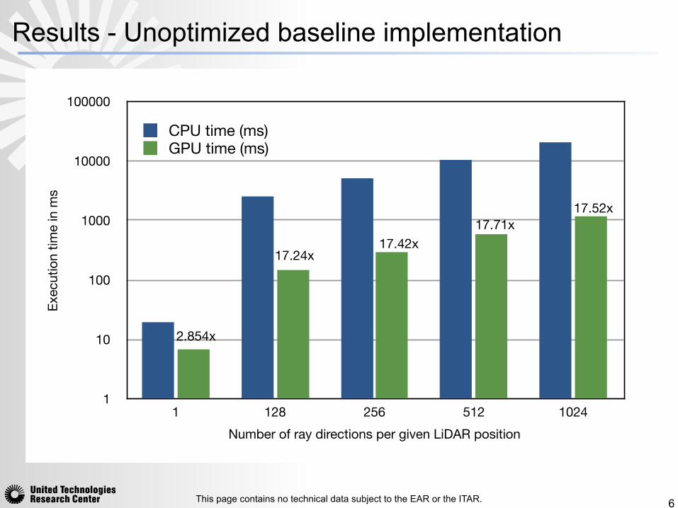
CPU implementation: compute-intensive, as each
triangle is visited multiple times for multiple ray directions.
GPU implementation: baseline implementation -
unoptimized memory optimized
implementation: cache ray directions in GPU shared memory, utilize GPU’s atomic functions to modify the data in the shared memory location and prevent race conditions.
This page contains no technical data subject to the EAR or the ITAR.
1
10
100
1000
10000
100000
1 128 256 512 1024
Exec
utio
n tim
e in
ms
Number of ray directions per given LiDAR position
CPU time (ms)GPU time (ms)
2.854x
17.24x17.42x
17.71x17.52x
Results - Unoptimized baseline implementation
6

This page contains no technical data subject to the EAR or the ITAR.
1
10
100
1000
10000
100000
1 128 256 512 1024
Exec
utio
n tim
e in
ms
Number of ray directions per given LiDAR position
CPU time (ms) GPU time (ms)
2.854x
46.42x 89x 148x179x
Results - Memory optimized implementation
7
This page contains no technical data subject to the EAR or the ITAR.
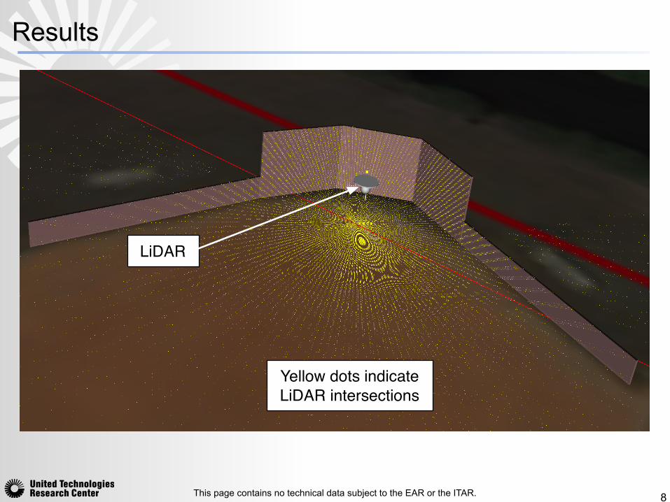
LiDAR
Yellow dots indicate LiDAR intersections
Results
8

This page contains no technical data subject to the EAR or the ITAR.
Results
9

This page contains no technical data subject to the EAR or the ITAR.
Conclusion
The optimized shared memory implementation gives 10x more speedup as compared to the naive implementation on the GPU platform.
Future research efforts may also address a customized FPGA implementation for comparing the latency and throughput between GPUs and FPGAs.
10

This page contains no technical data subject to the EAR or the ITAR.
Backup
11

This page contains no technical data subject to the EAR or the ITAR.
Algorithm
12
for r = 0 to R, where R is the maximum number of rays in a
given LiDAR position do
for each triangle 2 scene do
~t = O � Xedge1 = Y � Xedge2 = Z � X~p =
~D ⇥ edge2, where ⇥ denotes cross product
det = edge1 · ~pdet = 1/detu = (
~t · ~p) ⇤ det~q =
~t ⇥ edge1v = (
~D · ~q) ⇤ detif (u < 0.0||u > 1.0) thenreturn 0
else if (v < 0.0||(u + v) > 1.0) thenreturn 0
else
return (edge2 · ~q) ⇤ detend if
end for
end for