accelerating 4g network performance - netronome · pdf filebackward compatibility and...
TRANSCRIPT
WHITE PAPER
page 1 of 9Netronome Systems, Inc.
INTRODUCTIONVirtual Evolved Packet Core (vEPC) is the core of the 3G and 4G mobile network used for ser-
vice provisioning for mobile users. The main functionality of the EPC is it acts as an interface
between the 3G and 4G radio interfaces and public IP networks. vEPC is implemented as vir-
tual machines (VMs) on COTS servers. These services involve transfer of voice, data and video
from a mobile device to an IP network. Netronome Agilio® SmartNICs provide a 5X increase
in vEPC bandwidth on the same number of CPU cores by using the OVS offload and SR-IOV
technologies.
Evolved Packet Core (EPC) has been deployed for many years in various platforms using
dedicated servers for mobile traffic workloads within the core network. Since mobile traffic is
increasing exponentially, the mobile operators are addressing this demand with investments
in network and compute appliances. In the EPC the processing of voice, data and video is
integrated into a single IP domain. The advancement in virtualization and network functions
virtualization (NFV) technologies has led to the implementation of the EPC components as
virtual machines on x86 servers. The implementation of the EPC components as virtual net-
working functions (VNFs) is termed as vEPC. In this white paper we discuss the advantages of
implementing the vEPC on x86 server with Netronome Agilio SmartNICs.
Accelerating 4G Network Performance OFFLOADING VIRTUALIZED EPC TRAFFIC ON AN OVS-ENABLED NETRONOME SMARTNIC
CONTENTSINTRODUCTION .....................................................................................................................................................1
4G WIRELESS NETWORK ARCHITECTURE .............................................................................................2
EVOLVED PACKET CORE IN 4G NETWORKS ..........................................................................................2
VIRTUALIZED EVOLVED PACKET CORE (vEPC) ...................................................................................3
vEPC PACKET FLOW AND TEST PARAMETERS ................................................................................... 4
PACKET FLOW IN THE vEPC ...........................................................................................................................5
CPU CORE MAPPING FOR NETRONOME AGILIO CX .........................................................................5
BENCHMARKS FOR THE vEPC ..................................................................................................................... 6
CONCLUSION ........................................................................................................................................................ 9
NETRONOME AGILIO®
SMARTNICS PROVIDE A
5X INCREASE IN vEPC
BANDWIDTH ON THE
SAME NUMBER OF CPU
CORES BY USING THE OVS
OFFLOAD AND SR-IOV
TECHNOLOGIES

WHITE PAPER: Accelerating 4G Network Performance
page 2 of 9Netronome Systems, Inc.
4G WIRELESS NETWORK ARCHITECTURE
MobileManagment Entity
(MME)
Serving Gateway(S-GW)
Cloud RANeNodeB
IP Network
S1-MME
Access Network Evolved Packet Core(EPC)
S11
S1-U SGiLTE-Uu
MobileDevice
PDN Gateway(P-GW)
Figure 1. 4G Wireless Network Architecture
The Figure 1 shows the components of the 4G LTE network. Following are the main compo-
nents of the 4G network:
1. Mobile Device – Any wireless device capable of transmitting and receiving data in a radio network.
2. eNodeB – Radio access node (base station) that communicates with the mobile device and connects with serving gateway (S-GW) on the other side using the GTP-U protocol.
3. MME (Mobile Management entity) – MME controls the signaling in 4G LTE NW, it is part of the control plane functionality.
4. S-GW (serving gateway) – Acts as a router, which forwards data between the base station and PDN gateway (P-GW).
5. P-GW (Packet data network gateway) – This is the termination point of the packet data interface towards the IP network. PDN is responsible for policy rule enforcement, packet filtering, DPI etc.
6. IP Network – P-GW connects to the provider’s IP services, which are part of the IMS (IP
multimedia services – voice, data & video).
EVOLVED PACKET CORE IN 4G NETWORKSEPC is all IP-based service provisioning for the 4G LTE network. EPC provides fast network
performance by separating the control and data planes in the LTE network. It reduces the hi-
erarchy between mobile network elements because in the EPC architecture, the data channels
are established through the EPC gateways (S-GW and P-GW).
The Major advantages of the EPC architecture in a 4G network are:
1. Backward compatibility and interworking with the 3G mobile network architecture.
2. Voice, data and video services are built on the IP network.
3. Scalability in terms of bandwidth, number of subscribers and terminal mobility.
4. High reliability of the services.

WHITE PAPER: Accelerating 4G Network Performance
page 3 of 9Netronome Systems, Inc.
VIRTUALIZED EVOLVED PACKET CORE (vEPC)The components of the EPC can be implemented in the dedicated servers, with the emer-
gence of cloud-based server architectures with NFV and SDN technologies, the EPC com-
ponents can be implemented as the VNFs on the x86 servers while still maintaining the high
availability and scaling requirements. The advantages of implementing the EPC into the VMs
are:
■■ Independence of vendor hardware
■■ Scalability (More VNFs can be instantiated on the same hardware if number of connections
or BW requirement increases)
In this paper, we describe the advantage of using Netronome Agilio SmartNICs over tradition-
al network adapters on a server. The test setup for the vEPC performance measurement is
shown in Figure 2 and Figure 3. Each of the boxes represents a physical Dell R730 server with
24 physical cores (48 NUMA hyper threaded cores -vCPUs).
The setup simulates a vEPC network, specifically for GPRS tunneling protocol for user plane
(GTP-u) data traffic, such as is used in the 4G Mobile Network. The benchmarks for the vEPC
have been performed for three parameters: network throughput, packet latency and CPU
utilization.
For the performance comparison, a traditional network interface card (NIC) and Agilio CX
(the Netronome 1x40G Agilio SmartNIC) is used on the eNodeB/MME and gateway (P/S-GW)
servers. The User Equipment (UE) and Public Data Network (PDN) servers are used with the
traditional NIC as they just act as packet source and sink for the mobile traffic.
The Agilio CX and traditional NIC are used with a 1x40Gb/s to 4x10Gb/s breakout cable with
two 10G fiber cables connected between adjacent servers to provide 20 Gb/s connectivity, so
the total end-to-end network bandwidth between the UE to Echo server is 20Gb/s (of total
40Gb/s available).
Figure 2.
Packet Gen.
20G 20G 20G
User Equipment (UE)
Xeon - 2x12 cores
VM(eNodeB/MME)
OVS (Kernel)
eNodeB/MME
Xeon - 2x12 cores
S-GW/P-GW
Xeon - 2x12 cores
Echo Server
Xeon - 2x12 cores
VM(SGW/PGW)
Packet Sink.(PDN)
OVS (Kernel)
Traditional NIC Traditional NIC Traditional NIC Traditional NIC
vEPC Test Setup with traditional Network Interface Card
THE ADVANTAGES OF
IMPLEMENTING THE EPC
INTO THE VMs ARE
INDEPENDENCE OF
VENDOR HARDWARE
AND SCALABILITY
WHITE PAPER: Accelerating 4G Network Performance
page 4 of 9Netronome Systems, Inc.
Packet Gen.
20G 20G 20G
User Equipment (UE)
Xeon - 2x12 cores
VM(eNodeB/MME)
eNodeB/MME
Xeon - 2x12 cores
S-GW/P-GW
Xeon - 2x12 cores
Echo Server
Xeon - 2x12 cores
VM(SGW/PGW)
Packet Sink.(PDN)
Traditional NICAgilio CX
OVS OVS
Agilio CXTraditional NIC
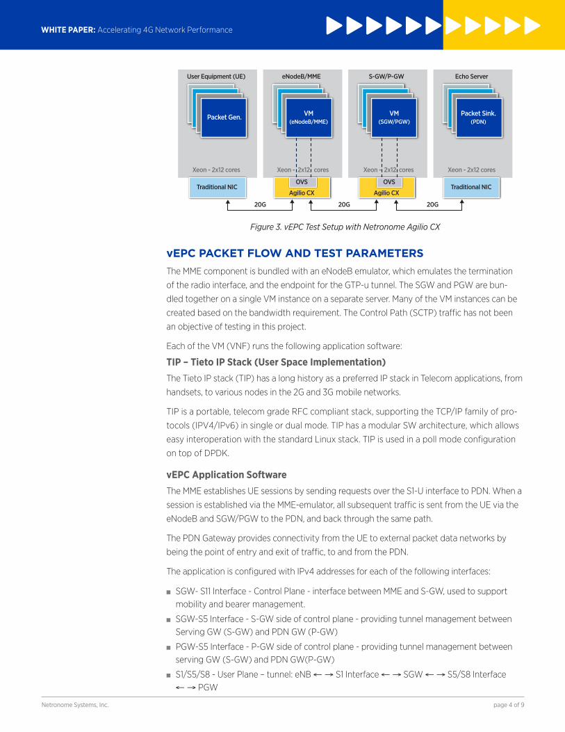
Figure 3. vEPC Test Setup with Netronome Agilio CX
vEPC PACKET FLOW AND TEST PARAMETERSThe MME component is bundled with an eNodeB emulator, which emulates the termination
of the radio interface, and the endpoint for the GTP-u tunnel. The SGW and PGW are bun-
dled together on a single VM instance on a separate server. Many of the VM instances can be
created based on the bandwidth requirement. The Control Path (SCTP) traffic has not been
an objective of testing in this project.
Each of the VM (VNF) runs the following application software:
TIP – Tieto IP Stack (User Space Implementation)The Tieto IP stack (TIP) has a long history as a preferred IP stack in Telecom applications, from
handsets, to various nodes in the 2G and 3G mobile networks.
TIP is a portable, telecom grade RFC compliant stack, supporting the TCP/IP family of pro-
tocols (IPV4/IPv6) in single or dual mode. TIP has a modular SW architecture, which allows
easy interoperation with the standard Linux stack. TIP is used in a poll mode configuration
on top of DPDK.
vEPC Application SoftwareThe MME establishes UE sessions by sending requests over the S1-U interface to PDN. When a
session is established via the MME-emulator, all subsequent traffic is sent from the UE via the
eNodeB and SGW/PGW to the PDN, and back through the same path.
The PDN Gateway provides connectivity from the UE to external packet data networks by
being the point of entry and exit of traffic, to and from the PDN.
The application is configured with IPv4 addresses for each of the following interfaces:
■■ SGW- S11 Interface - Control Plane - interface between MME and S-GW, used to support mobility and bearer management.
■■ SGW-S5 Interface - S-GW side of control plane - providing tunnel management between Serving GW (S-GW) and PDN GW (P-GW)
■■ PGW-S5 Interface - P-GW side of control plane - providing tunnel management between serving GW (S-GW) and PDN GW(P-GW)
■■ S1/S5/S8 - User Plane – tunnel: eNB ← → S1 Interface ← → SGW ← → S5/S8 Interface ← → PGW
WHITE PAPER: Accelerating 4G Network Performance
page 5 of 9Netronome Systems, Inc.
PACKET FLOW IN THE vEPCThe test system consists of four servers:
■■ “StressMe-UE” node – traffic generator, tests performer
■■ “eNB-MME” node – evolved Node B and Mobility Management Entity
■■ “SGW-PGW” node – Serving Gateway and Packet Data Network Gateway
■■ “EchoServer-PDN” node – Packet Data Network Simulator
The performance tests are conducted with a number of separate channels in parallel that
extends end-to-end, between the StressMe-UE and EchoServer-PDN nodes, running through
eNB-MME and SGW-PGW, making each channel independent. Each vEPC instance is running
in its own VM with separate memory spaces, virtual cores mapped to the physical cores on
the server, L1 and L2 cache.
All VMs are started up before the test is run. Traffic is TCP, generated with iperf3 in client
mode on the UE node, and terminated by iperf3 in server mode on the PDN node.
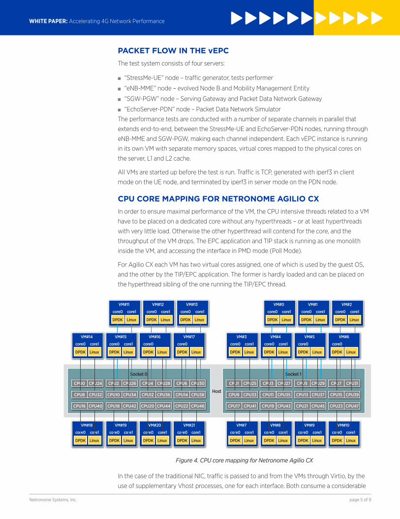
CPU CORE MAPPING FOR NETRONOME AGILIO CX In order to ensure maximal performance of the VM, the CPU intensive threads related to a VM
have to be placed on a dedicated core without any hyperthreads – or at least hyperthreads
with very little load. Otherwise the other hyperthread will contend for the core, and the
throughput of the VM drops. The EPC application and TIP stack is running as one monolith
inside the VM, and accessing the interface in PMD mode (Poll Mode).
For Agilio CX each VM has two virtual cores assigned, one of which is used by the guest OS,
and the other by the TIP/EPC application. The former is hardly loaded and can be placed on
the hyperthread sibling of the one running the TIP/EPC thread.
Figure 4.
Socket 0
DPDK Linux
VM#11
core0 core1
DPDK Linux
VM#12
core0 core1
DPDK Linux
VM#13
core0 core1
DPDK Linux
VM#14
core0 core1
DPDK Linux
VM#15
core0 core1
DPDK Linux
VM#16
core0
DPDK Linux
VM#17
core0
DPDK Linux
VM#18
core0 core1
DPDK Linux
VM#19
core0 core1
DPDK Linux
VM#20
core0
DPDK Linux
VM#21
core0
Host
CPU0 CPU24 CPU2 CPU26 CPU4 CPU28 CPU6 CPU30
CPU8 CPU32 CPU10 CPU34 CPU12 CPU36 CPU14 CPU38
CPU16 CPU40 CPU18 CPU42 CPU20 CPU44 CPU22 CPU46
Socket 1
CPU1 CPU25 CPU3 CPU27 CPU5 CPU29 CPU7 CPU31
CPU9 CPU33 CPU11 CPU35 CPU13 CPU37 CPU15 CPU39
CPU17 CPU41 CPU19 CPU43 CPU21 CPU45 CPU23 CPU47
DPDK Linux
VM#0
core0 core1
DPDK Linux
VM#1
core0 core1
DPDK Linux
VM#2
core0 core1
DPDK Linux
VM#3
core0 core1
DPDK Linux
VM#4
core0 core1
DPDK Linux
VM#5
core0
DPDK Linux
VM#6
core0
core1 core1
DPDK Linux
VM#7
core0 core1
DPDK Linux
VM#8
core0 core1
DPDK Linux
VM#9
core0
DPDK Linux
VM#10
core0core1 core1
CPU core mapping for Netronome Agilio CX
In the case of the traditional NIC, traffic is passed to and from the VMs through Virtio, by the
use of supplementary Vhost processes, one for each interface. Both consume a considerable
WHITE PAPER: Accelerating 4G Network Performance
page 6 of 9Netronome Systems, Inc.
amount of CPU power. In addition, traffic is delivered from the NIC by the use of IRQs, which
also consumes about 50% of a core. Thus the VM with traditional requires 3-4 dedicated
cores, to run efficiently and without contending with other VMs for the same CPU resources.
BENCHMARKS FOR THE vEPCIn the test setup described above the throughput, latency and CPU utilization benchmarks
are measured while running the 4G simulated traffic through the emulated eNodeB and vEPC
mobile core. For the comparison, traditional NICs and Netronome Agilio CX are used on eNo-
deB and vEPC servers in two different measurements with the same traffic patterns.
Throughput BenchmarksThe throughput is measured in terms of million packets per second (Mpps) for different pack-
et sizes The throughput increases as the number of VMs increase on the eNB and vEPC server
as each VM has a limit to the number of packets it can process.
Traditional NICWith the traditional NIC on the eNB and vEPC server, we need 3.3 cores per VM as it uses
Virtio. These 3.3 cores are used for the following functionality:
■■ DPDK-thread inside the VM which is mapped to one of the VM threads on the host.
■■ Vhost 1, relaying traffic between one port on the NIC to the Hypervisor
■■ Vhost 2, relaying traffic between the other port on the NIC to the Hypervisor
■■ Interrupt Requests arriving from the NIC
Since 3.3 cores are used for the single VM, only 7 VMs can be created with a 24-core dual slot
Xeon server.
Agilio CX Since the Agilio CX is running the OVS offload Agilio software and using the PCI SR-IOV func-
tionality, it does not have the overhead of the Vhost and interrupt processing as in case of the
traditional NIC. The VM implementation on the Dell server with Agilio CX takes only about 1.1
CPU cores. Therefore, on a dual-socket 24 core Dell R730 server, up to 22 VMs can be imple-
mented.
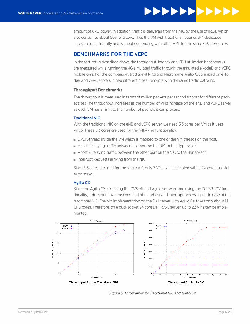
Figure 5. Throughput for Traditional NIC and Agilio CX
WHITE PAPER: Accelerating 4G Network Performance
page 7 of 9Netronome Systems, Inc.
As seen in Figure 5, for 128B packets with maximum number of VMs (7) the traditional NIC
can achieve 2.5 Mpps (2.9 Gb/s). The Agilio CX SmartNIC can generate performance of
13Mpps (15.5Gb/s for 128B packet) with up to 22 VMs on the same server.
In the case of Agilio CX, the throughput growth rate flattens after the 16th VM, and stays at
that level even with more VMs added. This means that performance faces bandwidth bottle-
neck; one possible cause may be the ‘slow’ QPI bus between the NUMA nodes which congests
the traffic.
Latency BenchmarksLatency is measured from end-to-end (UE server to PDN server) as in the current setup it is
not possible to breakdown the latency between different components of the data path such
as NIC latency, Application SW latency etc.
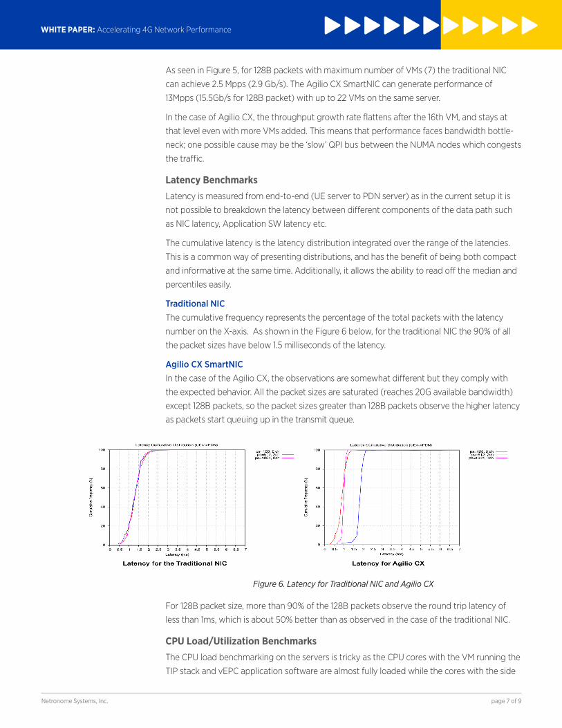
The cumulative latency is the latency distribution integrated over the range of the latencies.
This is a common way of presenting distributions, and has the benefit of being both compact
and informative at the same time. Additionally, it allows the ability to read off the median and
percentiles easily.
Traditional NICThe cumulative frequency represents the percentage of the total packets with the latency
number on the X-axis. As shown in the Figure 6 below, for the traditional NIC the 90% of all
the packet sizes have below 1.5 milliseconds of the latency.
Agilio CX SmartNICIn the case of the Agilio CX, the observations are somewhat different but they comply with
the expected behavior. All the packet sizes are saturated (reaches 20G available bandwidth)
except 128B packets, so the packet sizes greater than 128B packets observe the higher latency
as packets start queuing up in the transmit queue.
Figure 6. Latency for Traditional NIC and Agilio CX
For 128B packet size, more than 90% of the 128B packets observe the round trip latency of
less than 1ms, which is about 50% better than as observed in the case of the traditional NIC.
CPU Load/Utilization BenchmarksThe CPU load benchmarking on the servers is tricky as the CPU cores with the VM running the
TIP stack and vEPC application software are almost fully loaded while the cores with the side
WHITE PAPER: Accelerating 4G Network Performance
page 8 of 9Netronome Systems, Inc.
band processing and interrupt processing are lightly loaded.
For the CPU load benchmarking, we have collected the loads of 24 CPUs and averaged it to
plot the average CPU load on the left side of the Y-Axis. Additionally, on the right side of the
Y-axis, relative load is shown. The relative load indicates the CPU load per Mpps.
The Load Average is a number, which Linux reports together with the CPU load on each core.
Also, it is one global measure of the load on, and contention for the CPUs.
A core that is fully loaded will have a Load Average of 1, underloaded, a LA < 1, and over-
loaded, a LA > 1. A LA > 1, means that the core is fully occupied but other processes are also
waiting for CPU time slice. Therefore, the ideal LA is just below 1 per core.
Dell R730 servers used for the benchmarking have 24 cores and 48 vCPUs. So if fully loaded, it
would have a LA of 24. The hyper threads are counted in the LA total as well, but they cannot
be used as they will degrade the performance per VM, making the VMs interdependent. LA is
normalized as a percentage of the total so if Linux reports a LA of 6, it is translated into 25%
(6/24*100) loaded.
The relative LA is just the LA divided by the throughput so it represents the CPU load per
Mpps of throughput.
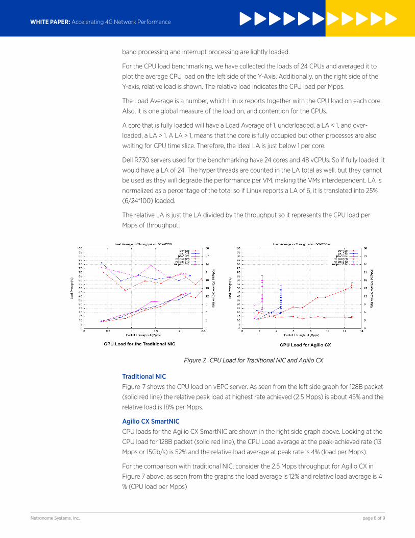
Figure 7. CPU Load for Traditional NIC and Agilio CX
Traditional NICFigure-7 shows the CPU load on vEPC server. As seen from the left side graph for 128B packet
(solid red line) the relative peak load at highest rate achieved (2.5 Mpps) is about 45% and the
relative load is 18% per Mpps.
Agilio CX SmartNICCPU loads for the Agilio CX SmartNIC are shown in the right side graph above. Looking at the
CPU load for 128B packet (solid red line), the CPU Load average at the peak-achieved rate (13
Mpps or 15Gb/s) is 52% and the relative load average at peak rate is 4% (load per Mpps).
For the comparison with traditional NIC, consider the 2.5 Mpps throughput for Agilio CX in
Figure 7 above, as seen from the graphs the load average is 12% and relative load average is 4
% (CPU load per Mpps)
Netronome Systems, Inc. 2903 Bunker Hill Lane, Suite 150 Santa Clara, CA 95054 Tel: 408.496.0022 | Fax: 408.586.0002 www.netronome.com
©2016 Netronome. All rights reserved. Netronome is a registered trademark and the Netronome Logo is a trademark of Netronome. All other trademarks are the property of their respective owners.
WP-vEPC-1/2017
WHITE PAPER: Accelerating 4G Network Performance
page 9 of 9
CONCLUSIONThe vEPC measurement results leads to the following conclusions:
■■ Traditional NIC peak rate achievable for vEPC load is 2.5 Mpps (2.9 Gbps).
■■ Agilio CX peak rate achievable for vEPC load is 13 Mpps (15 Gbps).
■■ Comparative results
■− Throughput: Server with Agilio CX can achieve the 5X (15 vs. 2.9) throughput of tradition-
al NIC.
■− Number of VMs: Server with Agilio CX can implement 3X more VMs than traditional NIC.
(22 vs. 7).
■− Latency: Round trip latencies are about 50% better than traditional NIC (1 milliseconds vs.
1.5 milliseconds).
■− CPU load: At the same line rate (2.9 Gbps) the CPU load observed is more than 4X lower
than the traditional NIC (45% vs. 12% on the average load and 18% vs. 4% on the relative
load).
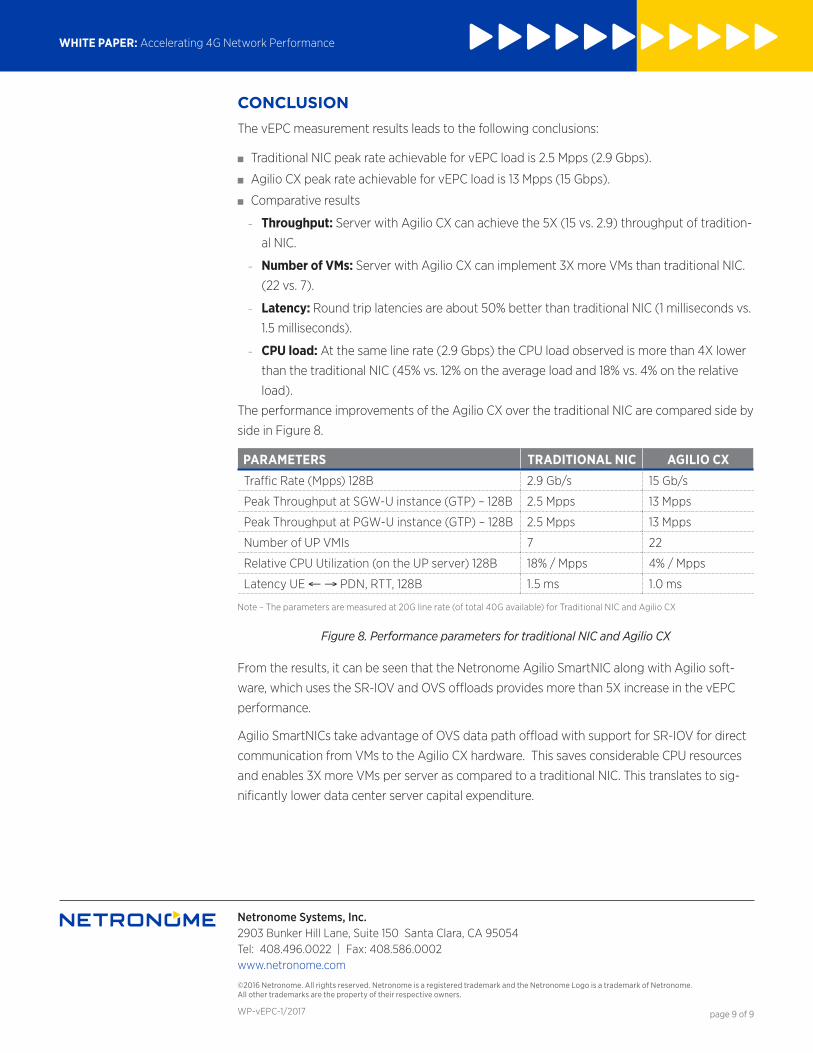
The performance improvements of the Agilio CX over the traditional NIC are compared side by
side in Figure 8.
PARAMETERS TRADITIONAL NIC AGILIO CXTraffic Rate (Mpps) 128B 2.9 Gb/s 15 Gb/s
Peak Throughput at SGW-U instance (GTP) – 128B 2.5 Mpps 13 Mpps
Peak Throughput at PGW-U instance (GTP) – 128B 2.5 Mpps 13 Mpps
Number of UP VMIs 7 22
Relative CPU Utilization (on the UP server) 128B 18% / Mpps 4% / Mpps
Latency UE ← → PDN, RTT, 128B 1.5 ms 1.0 ms
Note – The parameters are measured at 20G line rate (of total 40G available) for Traditional NIC and Agilio CX
Figure 8. Performance parameters for traditional NIC and Agilio CX
From the results, it can be seen that the Netronome Agilio SmartNIC along with Agilio soft-
ware, which uses the SR-IOV and OVS offloads provides more than 5X increase in the vEPC
performance.
Agilio SmartNICs take advantage of OVS data path offload with support for SR-IOV for direct
communication from VMs to the Agilio CX hardware. This saves considerable CPU resources
and enables 3X more VMs per server as compared to a traditional NIC. This translates to sig-
nificantly lower data center server capital expenditure.