accelerated aging methods for evaluating carbon...
TRANSCRIPT

Accelerated Aging Methods for Evaluating Carbon Electrode
Materials
IEEE Conference on Technologies for Sustainability SusTech 2014
Alex Bistrika (presenter)
Pavel Mardilovich Alex Yokochi

Outline
Introduction
1. Motivation for this work
2. Batteries and cycle life comparison
3. Commercially available Redox Flow Batteries (RFBs)
4. Importance of accelerated aging in these types of batteries
Experimental
1. Setup and reaction vessel assemblies
2. Assessing degradation via continuous charge mode experiments
3. Preliminary results and discussion
Conclusions/Future Work

(a)
(b)
24 hours
Meg
a-w
atts
2k
3k
4k
5k
1k
0
Meg
a-w
atts
10
20
30
40
0
(a) Daily profiles of wind power projected by 7x output in April 2005 for the year 2011 in Tehachapi, Califonia (Courtesy of ISO California). The canyon mid-day is characteristic of wind power generation.
(b) PV power over a span of 6 days in Spain (Courtesy of AES). The sudden drops are due to cloud cover. NOTE how wind and solar complement each other.
Sometimes the wind doesn’t blow
Cloud cover is devastating to solar
Intro: intermittent power

Intro: wind penetration
0
0 1
7870
0.45
r t
r t
k P eP t
k P e
k
r
O&M cost estimates for pumped hydro made by Hall et al. reported by NREL
?Shift in maintenance practices?

Introduction: need for big batteries
~100 [MWh]
~80 [MWh]

As depicted in the top figure, there is a wide range of power management needs. The broadest of which is clearly Renewable Energy Management.
The figure below shows the expected ranges for some available technologies.
NOTE the combined spectrum does not cover the entire power needs spectrum.
…Hybrid Energy Storage Systems (HESS)…
Figures Courtesy of ESA http://www.electricitystorage.org/ESA/home/
?
Intro: power management

Intro: battery technologies
a LAB: lead-acid batteries; NCB: nickel-cadmium batteries; VRB: all-vanadium redox flow batteries; LCB: lead- carbon ultrabatteries; Na-S: sodium-sulfur batteries; ZEBRA: Zeolite Battery Research Africa; C-LC: lithium- ion batteries of carbon anode and LiCoO2 cathode; LT-LFP: lithium-ion batteries of Li4Ti5O12 anode and LiFePO4 cathode; ZBB: zinc bromide flow batteries b This is dependent on the electrolyte reservoirs and can be engineered to be more than the listed values c The reactors must be drained when not in use Handbook of Energy Storage for Transmission and Distribution Applications, ESA, Barton and Infield IEEE Trans. Energy Convers 2004, http://www.mpoweruk.com/performance.htm
Type OCP Specific
Energy
Operating
Temperature
Discharge
Time
Self-discharge %
per month
Cycle-life Round-trip
Efficiency
V Wh/kg °C hrs @ 20 °C Deep %
LAB 2.1 25-40 -40 – 60 up to 8 4 – 50 1K 50 – 75
NCB 1.35 30-45 -10 – 45 up to 4 5 – 20 2K 55 – 70
VRB 1.4 10-20 10 – 40 4 – 12b 3 – 9 5K 65 – 80
LCB 2.1 25-40 -40 – 60 up to 4 - 3K -
Na-S 2.1 150-240 300 – 350 4 – 8 Negligible 4K 75 – 90
ZEBRA 2.6 95-120 300 – 350 4 – 8 Negligible 3K 75 – 90
C-LC 3.4 155 -25 – 40 up to 4 2 1K 94 – 99
LT-LFP 1.7 50-70 -25 – 40 up to 4 2 4K 94 – 99
ZBB 1.85 75 -30 – 50 4 – 12b <10c 5K 75 – 85
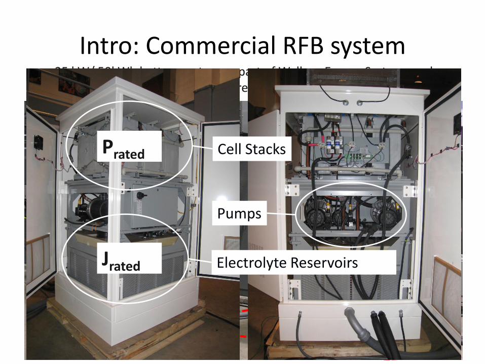
Intro: Commercial RFB system
25 kW/ 50kWh battery system as part of Wallace Energy Systems and Renewables Facility (WESRF) at Oregon State University
Cell Stacks
Electrolyte Reservoirs
Pumps
Prated
Jrated

Intro: electrode degradation
Old reactor cell stack 2X
X2 M
M2+ - pump pump
anol
yte
cath
olyt
e 2X
X2 2M
M2+
2X
X2 M2+
-
-
New reactor cell stack
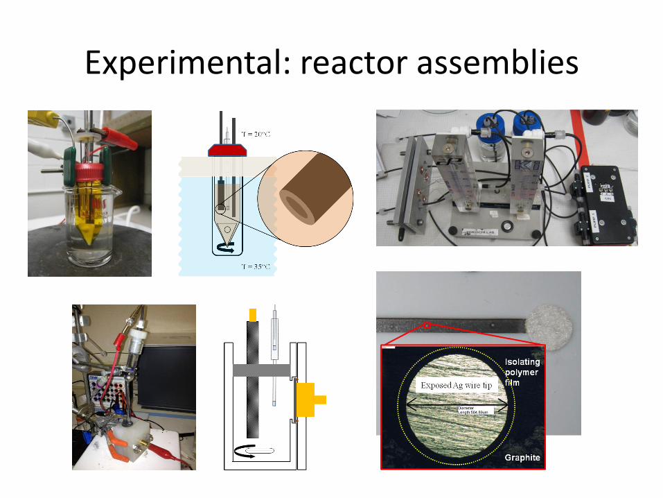
Experimental: reactor assemblies

Experimental: general process

Experimental: straightforward method
• Constant current death
• Potential is measured
• Identifiable reactions
• Constant voltage death
• Current is measured
• Observed activity loss
Time
Pote
nti
al
Time
Cu
rren
t
rxn2 primarily
rxn1 primarily
surface deactivation
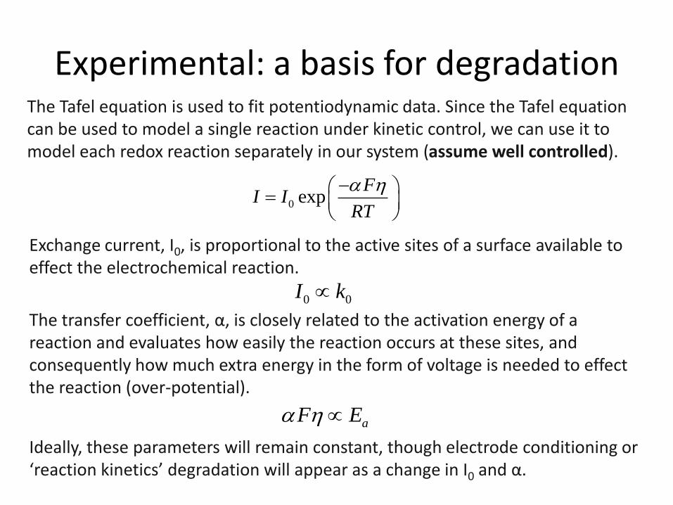
Exchange current, I0, is proportional to the active sites of a surface available to effect the electrochemical reaction. The transfer coefficient, α, is closely related to the activation energy of a reaction and evaluates how easily the reaction occurs at these sites, and consequently how much extra energy in the form of voltage is needed to effect the reaction (over-potential). Ideally, these parameters will remain constant, though electrode conditioning or ‘reaction kinetics’ degradation will appear as a change in I0 and α.
Experimental: a basis for degradation The Tafel equation is used to fit potentiodynamic data. Since the Tafel equation can be used to model a single reaction under kinetic control, we can use it to model each redox reaction separately in our system (assume well controlled).
0 expF
I IRT
0 0I k
aF E

Experimental: potantiostatic
a) Plot showing electrode (cloth) death by applying a constant potential with the straight forward method
b) Plot showing electrode (sintered graphite) death by calculating the theoretical current from measured Tafel parameters
0
20
40
2 40 800 16000 320000
i /
mA
cm
-2
C / mAh cm-2
Graphite
η = 100 [mV]
0
20
40
2 40 800 16000 320000
i /
mA
cm
-2
C / mAh cm-2
Cloth
η = 100 [mV]
(a)
(b)

Experimental: galvanostatic
a) Plot showing electrode (cloth) death by applying a constant current for bromide/bromine couple
b) Plot showing electrode (cloth) death by applying a constant current for chloride/chlorine couple
0
2
4
6
8
0.1 1 10 100
Po
ten
tial
v. S
HE
C / mAh cm-2
Cloth
i = 40 [mA cm-2]
0
2
4
6
8
0.1 1 10 100
Pote
nti
al v
. S
HE
C / mAh cm-2
Cloth
i = 40 [mA cm-2]
(a)
(b)

Experimental: discussion
Observations • There are two stages of degradation
that can be observed by measuring current at a constant potential for sintered graphite and graphitized cloth – One involves the irreversible
oxidative damage arising from continuous oxidation of the anion species
– And the second is likely due to the undesired electrolysis of water
• The individual stages for the straightforward method differ in onset as might be expected because the oxidation of chloride occurs outside the water oxidation window – This in turn suggests that using KCl as
an aging bath for accelerated aging of electrodes in an aqueous electrochemical system may be misleading and unrepresentative
Suggested alternative • Collect potentiodynamic data
throughout the aging test to provide insight as to the degradation mechanism(s) predominantly responsible for degradation at each stage
• Pre-oxidize the electrode surface with an electrochemically inactive anion species that has a tendency to also intercalate – this can be expected to catalyze the undesired water electrolysis reaction even in representative electrolyte baths
• Remove the more vulnerable active sites by a peroxide rinse prior to aging

Conclusion and future work
Conclusions • The potentiodynamic data collection
method allowed for greater insight of individual degradation mechanisms – By measuring the model parameters directly,
consideration whether the degradation is due to the elimination of active surface sites or undesired surface chemistry, is made possible
• Pre-oxidation of carbon surface catalyzes the undesired water electrolysis reaction – Pre-oxidizing the electrode surface with a strong
oxidizing agent can further shorten the aging duration
• A quantitative assessment of charge passed through an electrode surface for a certain (isolated) undesired reaction can be used to generate a cycle life model that can accurately predict the number of cycles it would take to reach a standard level of poor battery performance – From the preliminary evaluation it was
determined that the parameters involved in this calculation would include at minimum the following: 1) the operating current density, 2) the percent capacity being cycled on average, and reaction ratio between the desired and undesired reaction.
Future Work • Establish the effect current density has on
the electrochemical reaction ratio for a given electrochemical system and measure the charge required to observe surface deactivation – By performing a series of potentiostatic deaths at
various applied over-potentials
• Test various chemical pre-treatments that may favorably shift the reaction ratio – Pre-oxidizing the electrode surface with a strong
oxidizing agent and activating the surface
Acknowledgements • The Oregon State Venture Development
Fund and Oregon Built Environment and Sustainable Technologies Center for funding. Thanks!

Thanks!
www.cartoonstock.com
Alex Bistrika Phone: 541.829.3166 email: [email protected] Web: www.NRGindependence.com
Questions?