ac70e manual v1.1 - cfp techcfptech.co.za/wp-content/uploads/2011/09/ac70e-manual-v1.pdf · this...
TRANSCRIPT
1
FOREWORD
Thank you for using AC70E series inverter produced by Veichi Electric Co.Ltd
AC70E series inverter is a new generation of high-performance mini -frequency inverter independently
developed by Veichi, With advanced control method and rich function design. Users will be satisfied by
the simplified PLC, PID adjustor, programming I/O terminal, RS485 interface, analog I/O terminal, and
other specific control functions for particular industries in the benefit of AC70E
This manual is the supporting data sheet for AC70E
This instruction manual includes save tips, instructions (messages) of installing wiring, keyboard
operation, simple function table, troubleshooting, maintenance only. For parameters setting detail, pls
read AC70 general used series manual or consult us. For the best results and safe operations with the
AC70 series, carefully read and keep this manual. Make sure it is handy for the ultimate user of the
inverters for reference.
To receive technical support related to the inverter, please contact the Veichi sales office or the dealer
from whom you purchased. You can also contact our Customer Service Center, and we will try our
best to help you.
We are sparing no effort to upgrade our products and regret not to issue prior notification if there is any
revision to this instruction manual. Pray for your consideration for the inconveniences

2
Chapter 1: Summarize 1.1 Safety requirements and cautions
To ensure safety of your health, equipment and property, please read this chapter carefully before use
the frequency inverter and act in compliance with the instructions while carrying, installing, debugging,
running and overhauling the frequency inverter.
Warn sign and meaning
Danger: it will cause danger of serious injuries and even death while operating against the rules
Caution: it will cause danger of light injuries or equipment destruction while operating against the rules
Qualified operation
Only qualified person after professional train can operate the equipment.The operator must be with
professional train, familiar with installation, wiring, running and maintain of equipment, and can deal
emergency case.
Safe guide
Warn sign is for safe, to prevent operator from hurt and prevent this product and relating equipment
from being damaged. Before operating, be sure to carefully read the manual about safety, installation,
operation and maintenance and obey to the safe rules and warn sign.
Right transport, store, installation and careful operation and maintenance is most important for inverter safe run. In
transport and store process, make sure the inverter is free from impact and vibration. It must be stored where is dry,
without corrosive air and conductive dust, temperature lower than 60 . This product carries dangerous voltage and controls driver machine with potential danger. If not abide the
regulations or requirements in this manual, there is danger of body injury even death and machine system damage. Do not wire while the power is conneted. Otherwise there is danger of death for electric shock. Before wiring,
inspection, maintenance, please cut power supply of all related equipments and ensure mains DC voltage in safe
range. And please do operation after 5 mins. Power wire, motor wire and control wire should be all connected firmly. Earth must be reliable and earth resistance
must be lower than 10Ω. Human body electrostatic will seriously damage inner sensitive components. Before operation, please follow ESD
measures. Otherwise there is danger of iverter damage. Inverter output voltage is pulse wave. If components such as capacitor what improves power factor and
pressure-sensitive resistance for anti-thunder and so on are installed at the output side, please dismantle or change
to input side. No switch components such as breaker and contactor at the output side. (If there must be one, please make sure
the output current is 0 while the switch acting). No matter where the fault is, there is danger of serious accident, even human body injury what means dangerous
malfunction possibility. So there must be additional external prevent measures or other safety devices, such as
independent current limiting switch, machinery fense and so on. Only used in application fields as maker stated. No use in equipments related to special fields such as emergency,
succor, ship, medical treatment, avigation, nuclear and etc. Only service department of the maker or its authorized service center or professional person trained and authorized
3
by Veich can maintain the products. They should be very familiar with the safety warning and operation gist in this
manual.
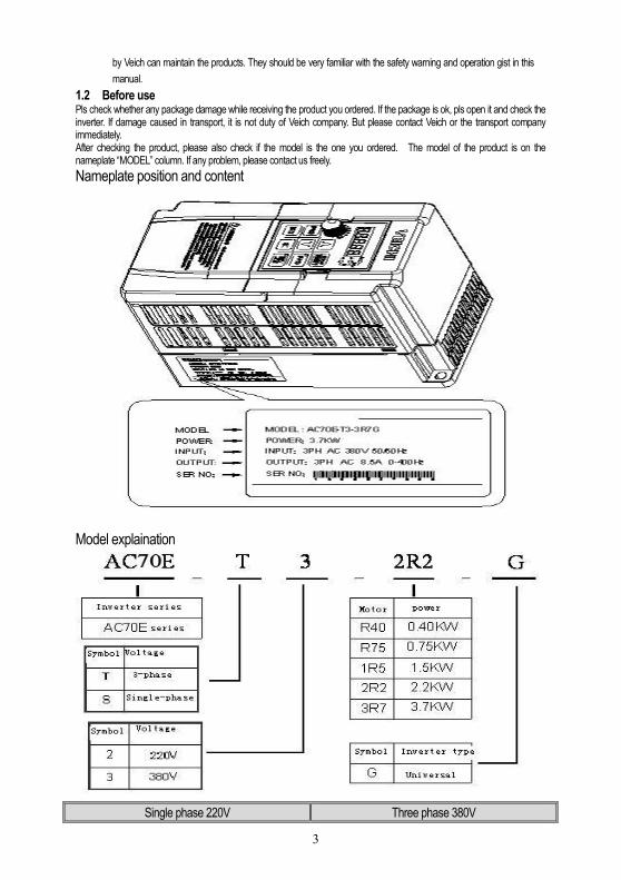
1.2 Before use Pls check whether any package damage while receiving the product you ordered. If the package is ok, pls open it and check the inverter. If damage caused in transport, it is not duty of Veich company. But please contact Veich or the transport company immediately. After checking the product, please also check if the model is the one you ordered. The model of the product is on the nameplate “MODEL” column. If any problem, please contact us freely.
Nameplate position and content
Model explaination
Single phase 220V Three phase 380V
4
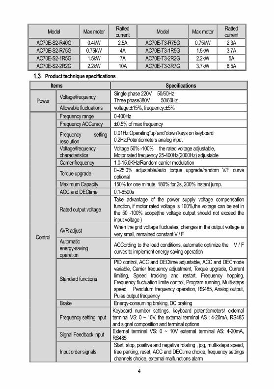
Model Max motor Ratted current
Model Max motor Ratted current
AC70E-S2-R40G 0.4kW 2.5A AC70E-T3-R75G 0.75kW 2.3A
AC70E-S2-R75G 0.75kW 4A AC70E-T3-1R5G 1.5kW 3.7A
AC70E-S2-1R5G 1.5kW 7A AC70E-T3-2R2G 2.2kW 5A
AC70E-S2-2R2G 2.2kW 10A AC70E-T3-3R7G 3.7kW 8.5A
1.3 Product technique specifications
Items Specifications
Power Voltage/frequency
Single phase 220V 50/60Hz Three phase380V 50/60Hz
Allowable fluctuations voltage:±15%, frequency:±5%
Control
Frequency range 0-400Hz
Frequency ACCuracy ±0.5% of max frequency
Frequency setting resolution
0.01Hz:Operating“up”and”down”keys on keyboard 0.2Hz:Potentiometers analog input
Voltage/frequency characteristics
Voltage 50% -100% the rated voltage adjustable, Motor rated frequency 25-400Hz(2000Hz) adjustable
Carrier frequency 1.0-15.0KHz/Random carrier modulation
Torque upgrade 0--25.0% adjustable/auto torque upgrade/random V/F curve optional
Maximum Capacity 150% for one minute, 180% for 2s, 200% instant jump.
ACC and DECtime 0.1-6500s
Rated output voltage
Take advantage of the power supply voltage compensation function, if motor rated voltage is 100%,the voltage can be set in the 50 -100% scope(the voltage output should not exceed the input voltage )
AVR adjust When the grid voltage fluctuates, changes in the output voltage is
very small, remained constant V / F
Automatic energy-saving operation
ACCording to the load conditions, automatic optimize the V / F curves to implement energy saving operation
Standard functions
PID control, ACC and DECtime adjustable, ACC and DECmode variable, Carrier frequency adjustment, Torque upgrade, Current limiting, Speed tracking and restart, Frequency hopping, Frequency fluctuation limite control, Program running, Multi-steps speed, Pendulum frequency operation, RS485, Analog output, Pulse output frequency
Brake Energy-consuming braking, DC braking
Frequency setting input Keyboard number settings, keyboard potentiometers/ external terminal VS: 0 ~ 10V, the external terminal AS : 4-20mA, RS485 and signal composition and terminal options
Signal Feedback input External terminal VS: 0 ~ 10V external terminal AS: 4-20mA, RS485
Input order signals Start, stop, positive and negative rotating , jog, multi-steps speed, free parking, reset, ACC and DECtime choice, frequency settings channels choice, external malfunctions alarm
5
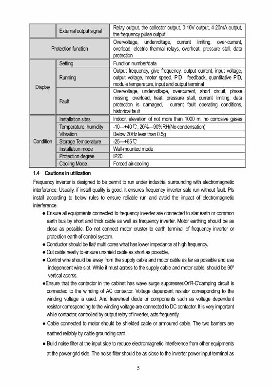
External output signal Relay output, the collector output, 0-10V output, 4-20mA output, the frequency pulse output
Protection function Overvoltage, undervoltage, current limiting, over-current, overload, electric thermal relays, overheat, pressure stall, data protection
Display
Setting Function number/data
Running Output frequency, give frequency, output current, input voltage, output voltage, motor speed, PID feedback, quantitative PID, module temperature, input and output terminal
Fault
Overvoltage, undervoltage, overcurrent, short circuit, phase missing, overload, heat, pressure stall, current limiting, data protection is damaged, current fault operating conditions, historical fault
Condition
Installation sites Indoor, elevation of not more than 1000 m, no corrosive gases and direct sunlight Temperature, humidity -10—+40, 20%—90%RH(No condensation)
Vibration Below 20Hz less than 0.5g
Storage Temperature -25—+65
Installation mode Wall-mounted mode
Protection degree IP20
Cooling Mode Forced air-cooling
1.4 Cautions in utilization
Frequency inverter is designed to be permit to run under industrial surrounding with electromagnetic
interference. Usually, if install quality is good, it ensures frequency inverter safe run without fault. Pls
install according to below rules to ensure reliable run and avoid the impact of electromagnetic
interference.
Ensure all equipments connected to frequency inverter are connected to star earth or common
earth bus by short and thick cable as well as frequency inverter. Motor earthing should be as
close as possible. Do not connect motor cruster to earth terminal of frequency inverter or
protection earth of control system.
Conductor should be flat/ multi cores what has lower impedance at high frequency.
Cut cable neatly to ensure unshield cable as short as possible.
Control wire should be away from the supply cable and motor cable as far as possible and use
independent wire slot. While it must across to the supply cable and motor cable, should be 90º
vertical acorss.
Ensure that the contactor in the cabinet has wave surge suppresser.Or‘R-C’damping circuit is
connected to the winding of AC contactor. Voltage dependent resistor corresponding to the
winding voltage is used. And freewheel diode or components such as voltage dependent
resistor corresponding to the winding voltage are connected to DC contactor. It is very important
while contactor, controlled by output relay of inverter, acts frequently.
Cable connected to motor should be shielded cable or armoured cable. The two barriers are
earthed reliably by cable grounding card.
Build noise filter at the input side to reduce electromagnetic interference from other equipments
at the power grid side. The noise filter should be as close to the inverter power input terminal as
6
possible. Meantime, the filter must earth reliably as the inverter.
Build noise filter at the output side to reduce radio interference and inductive disturbance. The
noise filter must be as close to the inverter output terminal as possible. Meantime, the filter must
earth reliably as the inverter.
Anytime, control circuit wire should be shielded cable.
Add zero phase reactor in power supply wire near inverter input terminal and add zero phase
reactor in the motor wire near inverter output terminal to reduce electromagnetic interference to
the inverter efficiently.
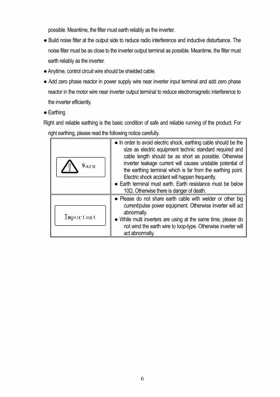
Earthing
Right and reliable earthing is the basic condition of safe and reliable running of the product. For
right earthing, please read the following notice carefully.
In order to avoid electric shock, earthing cable should be the size as electric equipment technic standard required and cable length should be as short as possible. Otherwise inverter leakage current will causes unstable potential of the earthing terminal which is far from the earthing point. Electric shock accident will happen frequently.
Earth terminal must earth. Earth resistance must be below 10Ω. Otherwise there is danger of death.
Please do not share earth cable with welder or other big current/pulse power equipment. Otherwise inverter will act abnormally.
While multi inverters are using at the same time, please do not wind the earth wire to loop-type. Otherwise inverter will act abnormally.

7
Chapter 2: Installation
2.1 Inverter stable running environment
Install environment is very important to the best use of this product for long time. Pls install this product
in the enviorment as the folling chart requirement.
Environment Requirement
Install place Indoor without direct sunshine
Install temperature -10 ~ +40(hanging type)
-10 ~ +45(cabinet type)
Store temperature -20 ~ +60
Humidity <95%RH, no condensation
Surrounding
Please install the inverter in place as below:
Place without oil mist、corrosive gases、flammable gases、 fust or etc.
Place without metal dust、oil、water or etc into inverter (please do not install
inverter on flammable material such as food and etc). Place without radioactive material or flammablematerial. Place without poisonous gases or liquid. Place with very little salification erosion. Place whihout direct sunshine.
Altitude <1000m
Vibration <10~20Hz∶9.8m/s2
<20~55Hz∶5.9m/s2
Installation and cooling
Inverter can not be installed horizontally, must be installed vertically. Please independently install high heating equipments such as braking resistor
and etc which can not be installed in the same cabinet with inverter, stalled at the air-in port of the inverter is strictly prohibited.
2.2 Installation notice and related requirement
AC70E inverter components

8
Installation direction and space
Single machine installation: to ensure enough ventilation and wiring space for inverter cooling, please
follow installation conditions as below.It should adopts hanging style or closet style with upright
installation and keeps enough space with surroundings or the wall.
Multi inverters paratactic installation: while install multi inverters in cabinet, please ensure installation
space as below.

9
2.3 Dimension of inverter and keyboard W1H1
WH
DD1
MODEL WW W1 H H1 D D1 INSTALLATION
APERTURE
AC70E-S2-R40G
88 75 142.5 129.5 142 132 ф5
AC70E-S2-R75G
AC70E-S2-1R5G
AC70E-T3-R75G
AC70E-T3-1R5G
AC70E-S2-2R2G 106 90 172 158 142 132 ф6
10
AC70E-T3-2R2G
AC70E-T3-3R7G
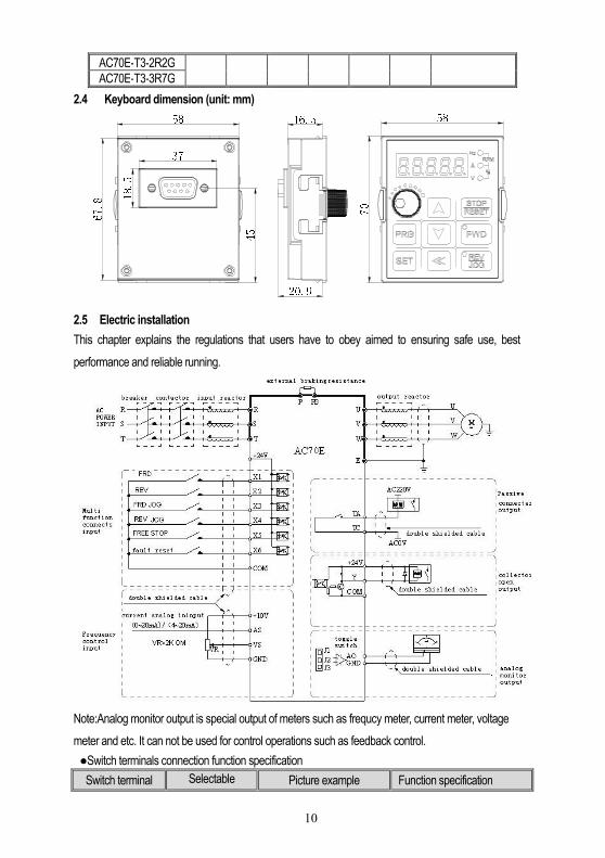
2.4 Keyboard dimension (unit: mm) 5870
16.520.9453718.567.8
58
2.5 Electric installation
This chapter explains the regulations that users have to obey aimed to ensuring safe use, best
performance and reliable running.
Note:Analog monitor output is special output of meters such as frequcy meter, current meter, voltage
meter and etc. It can not be used for control operations such as feedback control.
Switch terminals connection function specification
Switch terminal Selectable position
Picture example Function specification

11
J1 0.2--10kHz frequency output
J2 0--20mA current output 4--20mA current output
J3 0--10V voltage output
Suggested braking resistance
Single-phase 220V Single-phase 220V
Motor power
Resistance value
Resistance power
Braking moment
Motor power
Resistance value
Resistance power
Braking moment
0.4 kW 400Ω 100W 100% 0.75 kW
750Ω 150W 100%
0.75 kW 200Ω 120W 100% 1.5 kW
400Ω 300W 100%
1.5 kW 100Ω 300W 100% 2.2 kW
250Ω 400W 100%
2.2 kW 75Ω 300W 100% 3.7 kW
150Ω 500W 100%
Main circuit terminals
Terminal Name Function definition
(+) Braking resistance terminal
Used for external braking resistance to realize quick stop. PB
R/L
AC input terminal Used to connect AC power supply (R/L,S,T/N for T3 AC
input:R/L,T/N for S2AC input). S
T/N
U
AC output terminal Used to connect the motor or other sensitive/resistive load. V
W
Earth Earth terminal, earth resistance<10 OHM
Control loop terminals
12
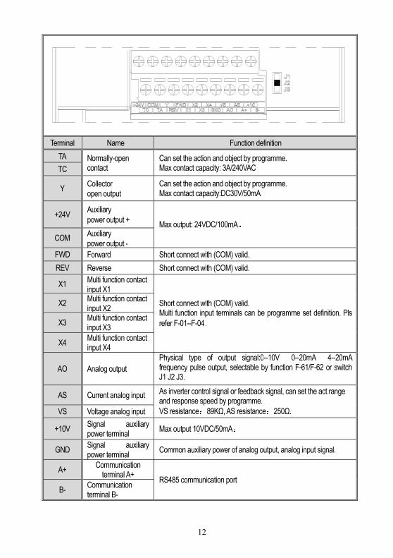
Terminal Name Function definition
TA Normally-open contact
Can set the action and object by programme. Max contact capacity: 3A/240VAC TC
Y Collector
open output
Can set the action and object by programme. Max contact capacity:DC30V/50mA
+24V Auxiliary
power output + Max output: 24VDC/100mA。
COM Auxiliary
power output -
FWD Forward Short connect with (COM) valid.
REV Reverse Short connect with (COM) valid.
X1 Multi function contact input X1
Short connect with (COM) valid. Multi function input terminals can be programme set definition. Pls
refer F-01--F-04。
X2 Multi function contact input X2
X3 Multi function contact input X3
X4 Multi function contact input X4
AO Analog output
Physical type of output signal:0--10V 0--20mA 4--20mA frequency pulse output, selectable by function F-61/F-62 or switch J1 J2 J3.
AS Current analog input As inverter control signal or feedback signal, can set the act range and response speed by programme.
VS resistance:89KΩ, AS resistance:250Ω. VS Voltage analog input
+10V Signal auxiliary power terminal
Max output 10VDC/50mA。
GND Signal auxiliary power terminal
Common auxiliary power of analog output, analog input signal.
A+ Communication
terminal A+ RS485 communication port
B- Communication terminal B-
13
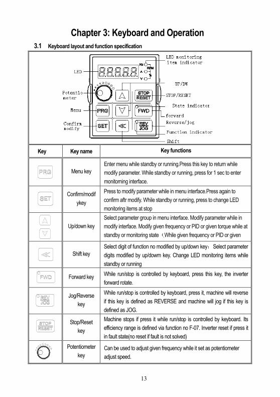
Chapter 3: Keyboard and Operation
3.1 Keyboard layout and function specification
Key Key name Key functions
Menu key
Enter menu while standby or running.Press this key to return while
modify parameter. While standby or running, press for 1 sec to enter
monitorning interface.
Confirm/modif
ykey
Press to modify parameter while in menu interface.Press again to
confirm aftr modify. While standby or running, press to change LED
monitoring items at stop
Up/down key
Select parameter group in menu interface. Modify parameter while in
modify interface. Modify given frequency or PID or given torque while at
standby or monitoring state(While given frequency or PID or given
torque are set by keyboard)
Shift key
Select digit of function no modified by up/down key;Select parameter
digits modified by up/dowm key. Change LED monitoring items while
standby or running
Forward key While run/stop is controlled by keyboard, press this key, the inverter
forward rotate.
Jog/Reverse
key
While run/stop is controlled by keyboard, press it, machine will reverse
if this key is defined as REVERSE and machine will jog if this key is
defined as JOG.
Stop/Reset
key
Machine stops if press it while run/stop is controlled by keyboard. Its
efficiency range is defined via function no F-07. Inverter reset if press it
in fault state(no reset if fault is not solved)
Potentiometer
key
Can be used to adjust given frequency while it set as potentiometer
adjust speed.

14
3.2 Indicating lamp meaning specification
Name State Meaning
Unit indicators
Hz Flashing display value is given frequency.
Hz On display value is output frequency.
A On display value is output current actual value.
V On display value is input voltage.
V Flashing display value is output voltage.
RPM On When "Hz" indicator and the "A" indicator light at the same time, display value is the motor speed.
% Flashing When the "A" indicator and the "V" indicator flashing at the same time, display value is gived PID value.
% On When the "A" indicator and the "V" indicator light at the same time, display value is the amount of PID feedback.
stateindicators
FWD On Frequency inverter turns forward.
FWD Flashing Frequency inverter reverses.
FWD Off Frequency inverter is close-down
Function indicators
REV/JOG On This key is defined as the jog function key.
15
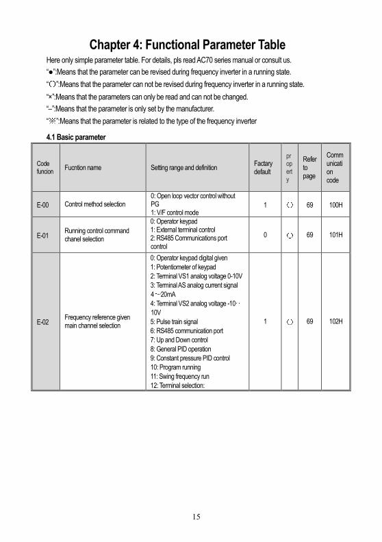
Chapter 4: Functional Parameter Table Here only simple parameter table. For details, pls read AC70 series manual or consult us.
“”:Means that the parameter can be revised during frequency inverter in a running state.
“〇”:Means that the parameter can not be revised during frequency inverter in a running state.
“×”:Means that the parameters can only be read and can not be changed.
“–”:Means that the parameter is only set by the manufacturer.
“※”:Means that the parameter is related to the type of the frequency inverter
4.1 Basic parameter
Code funcion
Fucntion name Setting range and definition Factary default
property
Refer to page
Communication code
E-00 Control method selection 0: Open loop vector control without PG 1: V/F control mode
1 〇 69 100H
E-01 Running control command chanel selection
0: Operator keypad 1: External terminal control 2: RS485 Communications port control
0 〇 69 101H
E-02 Frequency reference given main channel selection
0: Operator keypad digital given
1: Potentiometer of keypad
2: Terminal VS1 analog voltage 0-10V
3: Terminal AS analog current signal
4~20mA
4: Terminal VS2 analog voltage -10~10V
5: Pulse train signal
6: RS485 communication port
7: Up and Down control
8: General PID operation
9: Constant pressure PID control
10: Program running
11: Swing frequency run
12: Terminal selection:
1 〇 69 102H
16
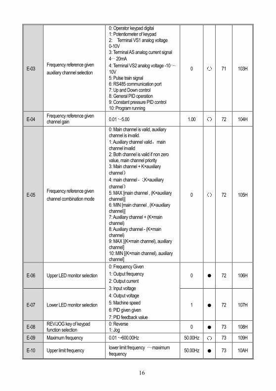
E-03 Frequency reference given
auxiliary channel selection
0: Operator keypad digital 1: Potentiometer of keypad 2: Terminal VS1 analog voltage 0-10V 3: Terminal AS analog current signal
4~20mA
4: Terminal VS2 analog voltage -10~10V 5: Pulse train signal 6: RS485 communication port 7: Up and Down control 8: General PID operation 9: Constant pressure PID control 10: Program running
0 〇 71 103H
E-04 Frequency reference given channel gain 0.01~5.00 1.00 〇 72 104H
E-05 Frequency reference given
channel combination mode
0: Main channel is valid, auxiliary channel is invalid.
1: Auxiliary channel valid,main
channel invalid 2: Both channel is valid if non zero value, main channel priority 3: Main channel + K×auxiliary
channel)
4: main channel -(K×auxiliary
channel)
5: MAX [main channel , (K×auxiliary channel)] 6: MIN [main channel , (K×auxiliary channel)] 7: Auxiliary channel + (K×main channel) 8: Auxiliary channel - (K×main channel) 9: MAX [(K×main channel), auxiliary channel] 10: MIN [(K×main channel), auxiliary channel]
0 〇 72 105H
E-06 Upper LED monitor selection
0: Frequency Given
1: Output frequency
2: Output current
3: Input voltage
4: Output voltage
5: Machine speed
6: PID given given
7: PID feedback value
0 72 106H
E-07 Lower LED monitor selection 1 72 107H
E-08 REV/JOG key of keypad function selection
0: Reverse 1: Jog
0 73 108H
E-09 Maximum frequency 0.01~600.00Hz 50.00Hz 〇 73 109H
E-10 Upper limit frequency lower limit frequency ~maximum
frequency 50.00Hz 73 10AH

17
E-11 Lower limit frequency 0.00~Upper limit frequency 0.00Hz 73 10BH
E-12 Lower limit frequency running mode
0: Stop 1: running with lower limit freqeuncy
1 73 10CH
E-13 Acceleration time 1 0.1~6500.0s ※ 74 10DH
E-14 Deceleration time 1 0.1~6500.0s ※ 74 10EH
E-15 Acceleration /deceleration mode selection
LED unit digit: decelerate /decelerate mode. 0: linear accelerate 1: S curve LED tens digit: Accelerate/decelerate time datum point. 0: Motor rated frequency 1: Maximum frequency LED hundreds digit: Equidistance stop function 0: Disable 1: Enable LED Thousands digit: reserve.
0000 74 10FH
E-16 Frequency given by digital keypad
lower limit frequency~Upper limit
frequency 75 110H
E-17 V/F curve mode
0: Constant torque curve
1: Descend torque curve(1.5 power
curve)
2: Descend torque curve(1.7 Power
curve)
3: Descend torque curve(2.0 Square
curve)
4: User define curve
0 〇 76 111H
E-18 Torque boost 0.0%~25.0% ※ 76 112H
E-19 Filter time constant 0.01~99.99 ※ 77 113H
E-20 Carrier frequency 0.7KHz~15.0KHz ※ 77 114H

18
E-21 Carrier characteristic
LED unit Digit: Associate of carrier frequency and output frequency configure. 0: Output frequency associate is disabled. 1: Output frequency associate is enabled. LED tens digit: Associate of carrier frequency and module temperature configure. 0: Module temperature associate is disabled. 1: Module temperature associate is enabled. LED Hundreds digit: PWM mode selection 0: Fixed PWM mode 2: Random PWM mode 1 LED Thousands digit: Inhibition of shock 0: Inhibition of shock is disabled 1: Inhibition of shock is enabled
1010 77 115H
E-22 V/F slip compensation 0%~200% 100% 〇 78 116H
E-23 Energy saving mode selection
LED unit digit: Auto energy saving
selection
0: disable
1: enable
LED tens digit: V/F slip
compensation
0: Disable
1: Enable
LED hundreds digit: Reserve
LED thousands digit: Reserve
0000 〇 78 117H
E-24 Voltage auto regulation function
0: Disable
1: Enable in full process
2:Disable only in deceleration
3: Enable only in deceleration
1 78 118H
E-25 Jog frequency 0.50Hz ~upper limit frequency 5.00Hz 79 119H
E-26 Jog acceleration time 0.1~6500.0s 2.0s 79 11AH
E-27 Jog deceleration time 0.1~6500.0s 2.0s 79 11BH
E-28 Starting frequency 0.00~60.00Hz 0.50Hz 〇 79 11CH
E-29 Starting frequency holding time 0.0~20.0s 0.0s 〇 79 11DH
19
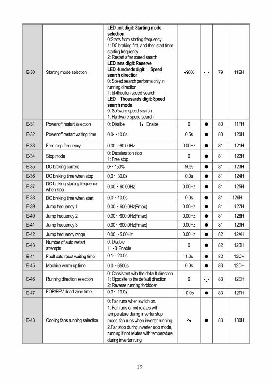
E-30 Starting mode selection
LED unit digit: Starting mode selection. 0:Starts from starting frequency 1: DC braking first, and then start from starting frequency 2: Restart after speed search LED tens digit: Reserve LED Hundreds digit: Speed search direction 0: Speed search performs only in running direction 1: bi-direction speed search LED Thousands digit: Speed search mode 0: Software speed search 1: Hardware speed search
※000 〇 79 11EH
E-31 Power off restart selection 0: Disalbe 1:Enalbe 0 80 11FH
E-32 Power off restart waiting time 0.0~10.0s 0.5s 80 120H
E-33 Free stop frequency 0.00~60.00Hz 0.00Hz 81 121H
E-34 Stop mode 0: Deceleration stop 1: Free stop
0 81 122H
E-35 DC braking current 0~150% 50% 81 123H
E-36 DC braking time when stop 0.0~30.0s 0.0s 81 124H
E-37 DC braking starting frequency when stop
0.00~60.00Hz 0.00Hz 81 125H
E-38 DC braking time when start 0.0~10.0s 0.0s 81 126H
E-39 Jump frequency 1 0.00~600.0Hz(Fmax) 0.00Hz 81 127H
E-40 Jump frequency 2 0.00~600.0Hz(Fmax) 0.00Hz 81 128H
E-41 Jump frequency 3 0.00~600.0Hz(Fmax) 0.00Hz 81 129H
E-42 Jump frequency range 0.00~5.00Hz 0.00Hz 82 12AH
E-43 Number of auto restart attempts
0: Disable
1~3: Enable 0 82 12BH
E-44 Fault auto reset waiting time 0.1~20.0s 1.0s 82 12CH
E-45 Machine warm up time 0.0~6500s 0.0s 83 12DH
E-46 Running direction selection 0: Consistent with the default direction 1: Opposite to the default direction 2: Reverse running forbidden.
0 〇 83 12EH
E-47 FOR/REV dead zone time 0.0~10.0s 0.0s 83 12FH
E-48 Cooling fans running selection
0: Fan runs when switch on.
1: Fan runs or not relates with
temperature during inverter stop
mode, fan runs when inverter running.
2.Fan stop during inverter stop mode,
running if not relates with temperature
during inverter ruing
※ 83 130H

20
E-49 Inverter protecting mode selection
LED unit digit: Overvoltage protecting selection during deceleration 0: Disable 1 Enable LED ten digit: Output phase missing protection 0: Disable 1 Enable LED hundred digit: Input phase missing protection 0: Disable 1 Enable LED thousand digit: Inverter overload, over heat protect mode selection. 0: Free stop 1: Running with current limit
0※11 84 131H
E-50 Coefficient value of electronic thermal
30%~120% (disable for value less
than 30 ) 0% 84 132H
E-51 Stall protecting current limit value
100%~250% 160 G 120 P 85 133H
E-52 Stall protecting DC bus voltage threshold value
105~160% 110% 85 134H
E-53 Dynamic braking and decelerating over voltage suppression threshold voltage
105~160% 135% 86 135H
E-54 Ratio of dynamic braking 0~100% 80% 86 136H
E-55 DC bus under voltage protecting value
60~90% 65% 86 137H
E-56 Reserve 86 138H
E-57 Reserve 86 139H
E-58 Reserve 86 13AH
E-59 Rotation speed display scale factor
0.1~2000.0% 100.0% 86 13BH
E-60 Ratio of inverter output voltage
50~110% 100% 〇 86 13CH
E-61 G/P type setting 0:G type 1:P type 0 〇 86 13DH
E-62 Speed search stabilizing keeping time
0.200~10.000s 0.600s 87 13EH
E-63 Parameters change protection
0: All the parameters changing is allowed 1: Only keyboard digital given parameter changing allowed 2: All the parameters prohibit changing
0 87 13FH
E-64 Parameter initialization
0: Null 1: Restores to factory default setting value 2: Clear fault record 3: Transfer parameters of inverter to
keypad and save. 4: Transfer parameters saved of
keypad to inverter
0 〇 87 140H
21
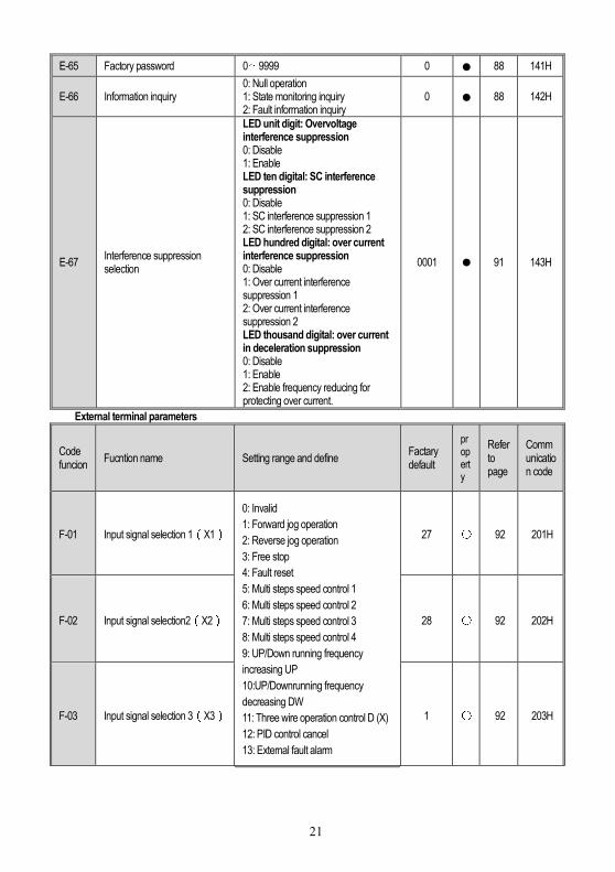
E-65 Factory password 0~9999 0 88 141H
E-66 Information inquiry 0: Null operation 1: State monitoring inquiry 2: Fault information inquiry
0 88 142H
E-67 Interference suppression selection
LED unit digit: Overvoltage interference suppression 0: Disable 1: Enable LED ten digital: SC interference suppression 0: Disable 1: SC interference suppression 1 2: SC interference suppression 2 LED hundred digital: over current interference suppression 0: Disable 1: Over current interference suppression 1 2: Over current interference suppression 2 LED thousand digital: over current in deceleration suppression 0: Disable 1: Enable 2: Enable frequency reducing for protecting over current.
0001 91 143H
External terminal parameters
Code funcion
Fucntion name Setting range and define Factary default
property
Refer to page
Communication code
F-01 Input signal selection 1(X1)
0: Invalid
1: Forward jog operation
2: Reverse jog operation
3: Free stop
4: Fault reset
5: Multi steps speed control 1
6: Multi steps speed control 2
7: Multi steps speed control 3
8: Multi steps speed control 4
9: UP/Down running frequency
increasing UP
10:UP/Downrunning frequency
decreasing DW
11: Three wire operation control D (X)
12: PID control cancel
13: External fault alarm
27 〇 92 201H
F-02 Input signal selection2(X2) 28 〇 92 202H
F-03 Input signal selection 3(X3) 1 〇 92 203H
22
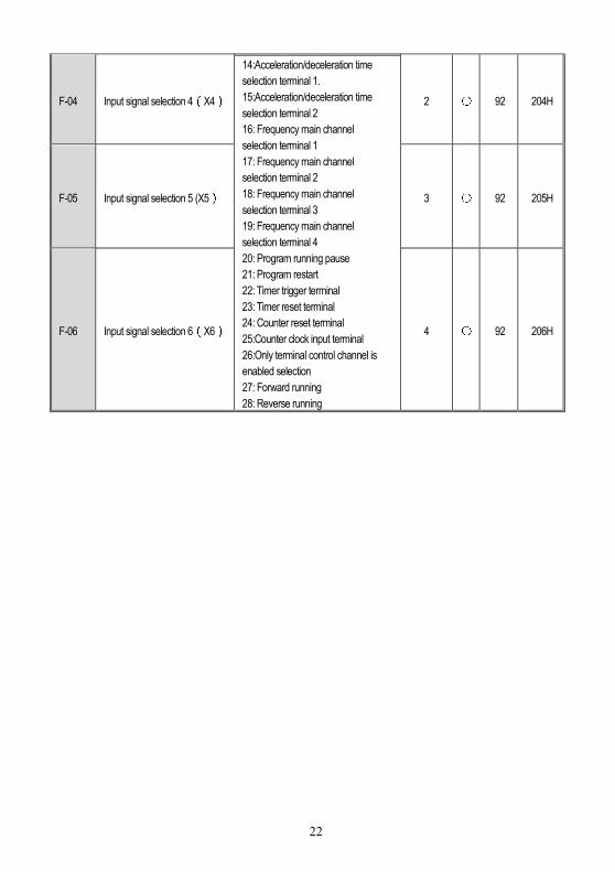
F-04 Input signal selection 4(X4)
14:Acceleration/deceleration time
selection terminal 1.
15:Acceleration/deceleration time
selection terminal 2
16: Frequency main channel
selection terminal 1
17: Frequency main channel
selection terminal 2
18: Frequency main channel
selection terminal 3
19: Frequency main channel
selection terminal 4
20: Program running pause
21: Program restart
22: Timer trigger terminal
23: Timer reset terminal
24: Counter reset terminal
25:Counter clock input terminal
26:Only terminal control channel is
enabled selection
27: Forward running
28: Reverse running
2 〇 92 204H
F-05 Input signal selection 5 (X5) 3 〇 92 205H
F-06 Input signal selection 6(X6) 4 〇 92 206H
23
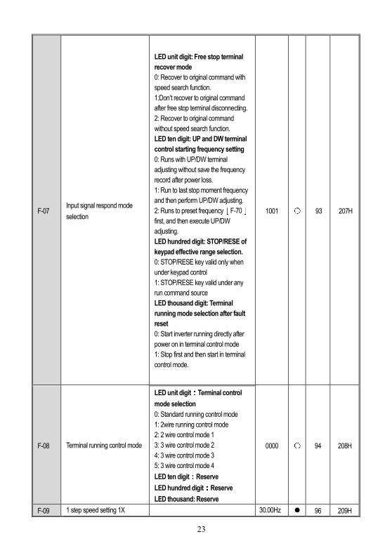
F-07 Input signal respond mode
selection
LED unit digit: Free stop terminal
recover mode
0: Recover to original command with
speed search function.
1:Don’t recover to original command
after free stop terminal disconnecting.
2: Recover to original command
without speed search function.
LED ten digit: UP and DW terminal
control starting frequency setting
0: Runs with UP/DW terminal
adjusting without save the frequency
record after power loss.
1: Run to last stop moment frequency
and then perform UP/DW adjusting.
2: Runs to preset frequency[F-70]first, and then execute UP/DW
adjusting.
LED hundred digit: STOP/RESE of
keypad effective range selection.
0: STOP/RESE key valid only when
under keypad control
1: STOP/RESE key valid under any
run command source
LED thousand digit: Terminal
running mode selection after fault
reset
0: Start inverter running directly after
power on in terminal control mode
1: Stop first and then start in terminal
control mode.
1001 〇 93 207H
F-08 Terminal running control mode
LED unit digit:Terminal control mode selection
0: Standard running control mode
1: 2wire running control mode
2: 2 wire control mode 1
3: 3 wire control mode 2
4: 3 wire control mode 3
5: 3 wire control mode 4
LED ten digit:Reserve LED hundred digit:Reserve LED thousand: Reserve
0000 〇 94 208H
F-09 1 step speed setting 1X 30.00Hz 96 209H

24
F-10 2 step speed setting 2X
0.00Hz~upper limit frequency
25.00Hz 96 20AH
F-11 3 step speed setting 3X 40.00Hz 96 20BH
F-12 4 step speed setting 4X 50.00Hz 96 20CH
F-13 5 step speed setting 5X 50.00Hz 96 20DH
F-14 6 step speed setting 6X 40.00Hz 96 20EH
F-15 7 step speed setting 7X 25.00Hz 96 20FH
F-16 8 step speed setting 8X 10.00Hz 96 210H
F-17 Reserve 97 211H
F-18 Reserve 97 212H
F-19 Speed search tracking speed 0.1~10.0% 0.2% 〇 97 213H
F-20 Voltage stores time 0.10S~10.00S 0.60S 〇 97 214H
F-21 Speed search respond current
threshold value 10%~200% 120% 〇 97 215H
F-22 Frequency reducing
acceleration time 0.1~6500.0s 2.0s 97 216H
F-23 Frequency reducing
acceleration time 0.1~6500.0s 1.0s 97 217H
F-24 Acceleration time 2
0.1~6500.0s
※ 98 218H
F-25 Deceleration time 2 ※ 98 219H
F-26 Acceleration time 3 ※ 98 21AH
F-27 Deceleration time 3 ※ 98 21BH
F-28 Acceleration time 4 ※ 98 21CH
F-29 Deceleration time 4 ※ 98 21DH
F-30 Relay output terminal
(TA,TB,TC)
0: Zero frequency (standby state)
1:Fault alarm 1. (Including fault auto
reset period. )
2: Fault alarm 2. (Not includes fault
auto reset period. )
3: Frequency arriving detection
4: Frequency level detection
5: Running statues
6: Reverse running
7: Under voltage of inverter
8: Overload pre-alarm
9: Output frequency reach upper limit
frequency
10. Output frequency reach lower limit
frequency
11. External fault stop
12. Timer times up
13. Counter reach maximum values
14. Counter reach setting values
15. PID feedback upper limit alarm
1 98 21EH
F-31 Output terminal Y1 4 98 21FH

25
F-32 Output terminal Y2
16. PID feedback lower limit alarm
17. Sensor broken
18.Program running cycle completed
19.Program running step completed
20:Dynamic braking processing
21: Output terminal control by external
7 98 220H
F-33 Frequency arriving detect bias
0.00~50.00Hz 1.00Hz 100 221H
F-34 Output frequency level
detection 0.00~600.0Hz 30.00Hz 100 222H
F-35 Output frequency level
detecting relay time 0.0~20.0s 0.0s 100 223H
F-36 Overload pre-alarm level 50~200% 150% 100 224H
F-37 Overload pre-alarm delay time 0.0~20.0s 1.0s 100 225H
F-38 Timer setting value 1~65000s 1s 100 226H
F-39 Counter maximum value 1~65000 1000 101 227H
F-40 Counter setting value 1~ Counter maximum value 100 101 228H
F-41 VS1 terminal input
voltage lower limit 0.00V~[F-42] 0.50V 101 229H
F-42 VS1 terminal input
voltage upper limit [F-41]~10.00V 9.50V 101 22AH
F-43 VS1 terminal input
voltage gain 0.01~5.00 1.00 101 22BH
F-44 VS2 terminal input
voltage lower limit -10.0V ~[F-45] 0.5V 101 22CH
F-45 VS2 terminal input
voltage upper limit [F-44]~10.0V 9.5V 101 22DH
F-46 VS2 terminal input
voltage gain 0.01~5.00 1.00 101 22EH
F-47 VS2 terminal input
voltage lower limit -1.00V~1.00V 0.00V 101 22FH
F-48
VS2 terminal input bipolar adjust and direction control
0: Bipolar adjust and direction control both invalid 1: Bipolar adjust and direction control both valid 2:Bipolar adjust valid, direction control invalid
0 101 230H
F-49
VS2 terminal input bipolar control zero hysteresis band
0.00V~3.00V 0.20V 102 231H
F-50 AS terminal input
current lower limit 0.00mA~[F-51] 4.20mA 103 232H
F-51 AS terminal input
current upper limit [F-50]~20.0mA 19.50mA 103 233H

26
F-52 AS terminal input current gain 0.01~5.00 1.00 103 234H
F-53 Pulse input frequency lower
limit 0.00KHz~[F-54] 0.00KHz 104 235H
F-54 Pulse input frequency upper
limit [F-53]~50.00KHz 10.00KHz 104 236H
F-55 Pulse input frequency gain 0.01~5.00 1.00 104 237H
F-56 Input lower limit correspond
setting frequency 0.00Hz~[F-57] 0.00Hz 104 238H
F-57 nput upper limit correspond
setting frequency [F-56]~maximum frequency 50.00Hz 104 239H
F-58 Input signal
characteristic selection
LED unit digit: VS1 input
characteristic selection
0: Positive characteristic
1: Negative characteristic
LED ten digit: AS input
characteristic selection
0: Positive characteristic
1: Negative characteristic
LED hundred digit: VS2 input
characteristic selection
0: Positive characteristic
1: Negative characteristic
LED thousand digit: Pulse input
characteristic selection
0: Positive characteristic
1: Negative characteristic
0000 104 23AH
F-59 Terminal analog input filtering time constant 0.01~5.00 0.50 105 23BH
F-60 Output terminal(AO1)selection
0: Output signal disable 1: Output frequency/speed 2: Output current 3: Given frequency/speed reference 4: PID given value 5: PID feedback value 6: DC bus voltage 7: Output voltage
1 105 23CH
F-61 Output terminal(AO2)selection
3 105 23DH
27
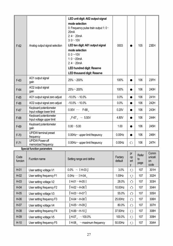
F-62 Analog output signal selection
LED unit digit: A02 output signal
mode selection
0: Frequency pulse train output 1: 0~20mA
2: 4~20mA
3: 0~10V
LED ten digit: A01 output signal
mode selection
0: 0~10V
1: 0~20mA
2: 4~20mA
LED hundred digit: Reserve
LED thousand digit: Reserve
0003 105 23EH
F-63 AO1 output signal gain
25%~200% 100% 106 23FH
F-64 AO2 output signal gain
25%~200% 100% 106 240H
F-65 AO1 output signal zero adjust -10.0%~10.0% 0.0% 106 241H
F-66 AO2 output signal zero adjust -10.0%~10.0% 0.0% 106 242H
F-67 Keyboard potentiometer Input voltage lower limit
0.00V ~[F-68] 0.20V 106 243H
F-68 Keyboard potentiometer Input voltage upper limit
[F-67]~ 5.50V 4.80V 106 244H
F-69 Keyboard potentiometer gain
0.00~5.00 1.00 106 245H
F-70 UP/DW terminal preset frequency
0.00Hz~upper limit freqeuncy 0.00Hz 106 246H
F-71 UP/DW Power-off memorized frequency
0.00Hz~upper limit freqeuncy 0.00Hz 〇 106 247H
Special function parameters
Code funcion
Fucntion name Setting range and define Factary default
property
Refer to page
Communication code
H-01 User setting voltage V1 0.0% ~[H-03] 3.0% 〇 107 301H
H-02 User setting frequency F1
0.0Hz~[H-04] 1.00Hz 〇 107 302H
H-03 User setting voltage V2 [H-01~H-05] 28.0% 〇 107 303H
H-04 User setting frequency F2
[H-02~H-06] 10.00Hz 〇 107 304H
H-05 User setting voltage V3 [H-03~H-07] 55.0% 〇 107 305H
H-06 User setting frequency F3
[H-04~H-08] 25.00Hz 〇 107 306H
H-07 User setting voltage V4 [H-05~H-09] 80.0% 〇 107 307H
H-08 User setting frequency F4
[H-06~H-10] 37.50Hz 〇 107 308H
H-09 User setting voltage V5 [H-07]~100.0% 100.0% 〇 107 309H
H-10 User setting frequency F5
[H-08]~maximum frequency 50.00Hz 〇 107 30AH
28
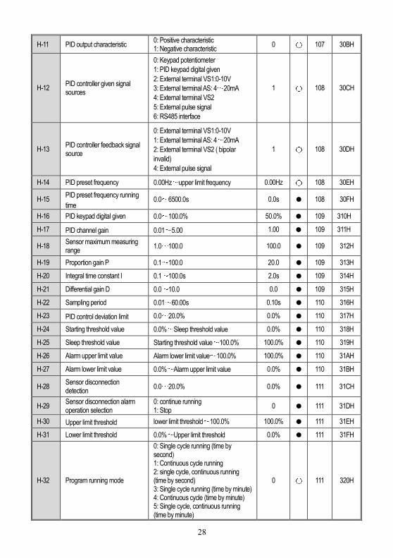
H-11 PID output characteristic 0: Positive characteristic 1: Negative characteristic
0 〇 107 30BH
H-12 PID controller given signal sources
0: Keypad potentiometer
1: PID keypad digital given
2: External terminal VS1:0-10V
3: External terminal AS: 4~20mA
4: External terminal VS2
5: External pulse signal
6: RS485 interface
1 〇 108 30CH
H-13 PID controller feedback signal source
0: External terminal VS1:0-10V
1: External terminal AS: 4~20mA
2: External terminal VS2 ( bipolar
invalid)
4: External pulse signal
1 〇 108 30DH
H-14 PID preset frequency 0.00Hz~upper limit frequency 0.00Hz 〇 108 30EH
H-15 PID preset frequency running
time 0.0~6500.0s 0.0s 108 30FH
H-16 PID keypad digital given 0.0~100.0% 50.0% 109 310H
H-17 PID channel gain 0.01~5.00 1.00 109 311H
H-18 Sensor maximum measuring range
1.0~100.0 100.0 109 312H
H-19 Proportion gain P 0.1~100.0 20.0 109 313H
H-20 Integral time constant I 0.1~100.0s 2.0s 109 314H
H-21 Differential gain D 0.0~10.0 0.0 109 315H
H-22 Sampling period 0.01~60.00s 0.10s 110 316H
H-23 PID control deviation limit 0.0~20.0% 0.0% 110 317H
H-24 Starting threshold value 0.0%~Sleep threshold value 0.0% 110 318H
H-25 Sleep threshold value Starting threshold value~100.0% 100.0% 110 319H
H-26 Alarm upper limit value Alarm lower limit value~100.0% 100.0% 110 31AH
H-27 Alarm lower limit value 0.0%~Alarm upper limit value 0.0% 110 31BH
H-28 Sensor disconnection detection
0.0~20.0% 0.0% 111 31CH
H-29 Sensor disconnection alarm operation selection
0: continue running 1: Stop
0 111 31DH
H-30 Upper limit threshold lower limit threshold~100.0% 100.0% 111 31EH
H-31 Lower limit threshold 0.0%~Upper limit threshold 0.0% 111 31FH
H-32 Program running mode
0: Single cycle running (time by second) 1: Continuous cycle running 2: single cycle, continuous running (time by second) 3: Single cycle running (time by minute) 4: Continuous cycle (time by minute) 5: Single cycle, continuous running (time by minute)
0 〇 111 320H
29
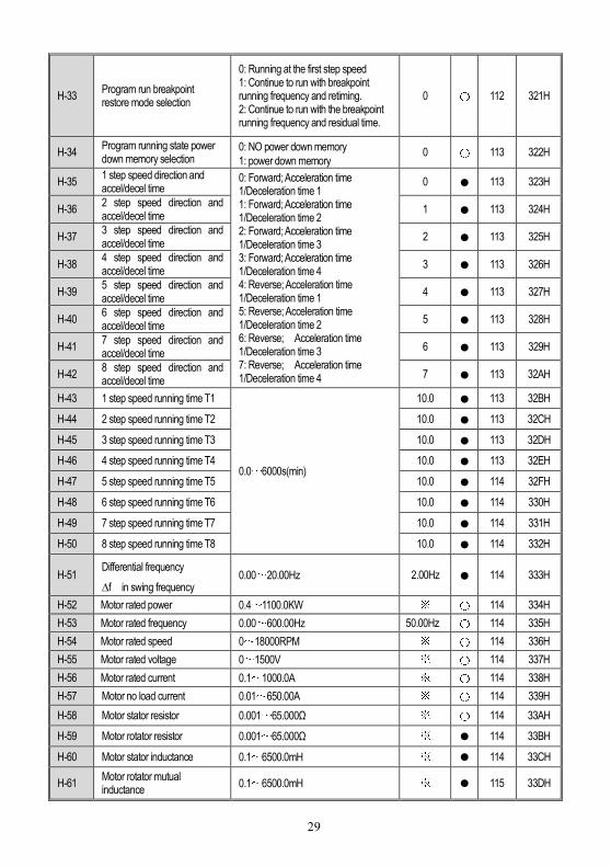
H-33 Program run breakpoint restore mode selection
0: Running at the first step speed 1: Continue to run with breakpoint running frequency and retiming. 2: Continue to run with the breakpoint running frequency and residual time.
0 〇 112 321H
H-34 Program running state power down memory selection
0: NO power down memory
1: power down memory 0 〇 113 322H
H-35 1 step speed direction and accel/decel time
0: Forward; Acceleration time 1/Deceleration time 1 1: Forward; Acceleration time 1/Deceleration time 2 2: Forward; Acceleration time 1/Deceleration time 3 3: Forward; Acceleration time 1/Deceleration time 4 4: Reverse; Acceleration time 1/Deceleration time 1 5: Reverse; Acceleration time 1/Deceleration time 2 6: Reverse; Acceleration time 1/Deceleration time 3 7: Reverse; Acceleration time 1/Deceleration time 4
0 113 323H
H-36 2 step speed direction and accel/decel time
1 113 324H
H-37 3 step speed direction and accel/decel time
2 113 325H
H-38 4 step speed direction and accel/decel time
3 113 326H
H-39 5 step speed direction and accel/decel time
4 113 327H
H-40 6 step speed direction and accel/decel time
5 113 328H
H-41 7 step speed direction and accel/decel time
6 113 329H
H-42 8 step speed direction and accel/decel time
7 113 32AH
H-43 1 step speed running time T1
0.0~6000s(min)
10.0 113 32BH
H-44 2 step speed running time T2 10.0 113 32CH
H-45 3 step speed running time T3 10.0 113 32DH
H-46 4 step speed running time T4 10.0 113 32EH
H-47 5 step speed running time T5 10.0 114 32FH
H-48 6 step speed running time T6 10.0 114 330H
H-49 7 step speed running time T7 10.0 114 331H
H-50 8 step speed running time T8 10.0 114 332H
H-51 Differential frequency
∆f in swing frequency 0.00~20.00Hz 2.00Hz 114 333H
H-52 Motor rated power 0.4~1100.0KW ※ 〇 114 334H
H-53 Motor rated frequency 0.00~600.00Hz 50.00Hz 〇 114 335H
H-54 Motor rated speed 0~18000RPM ※ 〇 114 336H
H-55 Motor rated voltage 0~1500V ※ 〇 114 337H
H-56 Motor rated current 0.1~1000.0A ※ 〇 114 338H
H-57 Motor no load current 0.01~650.00A ※ 〇 114 339H
H-58 Motor stator resistor 0.001~65.000Ω ※ 〇 114 33AH
H-59 Motor rotator resistor 0.001~65.000Ω ※ 114 33BH
H-60 Motor stator inductance 0.1~6500.0mH ※ 114 33CH
H-61 Motor rotator mutual inductance
0.1~6500.0mH ※ 115 33DH
30
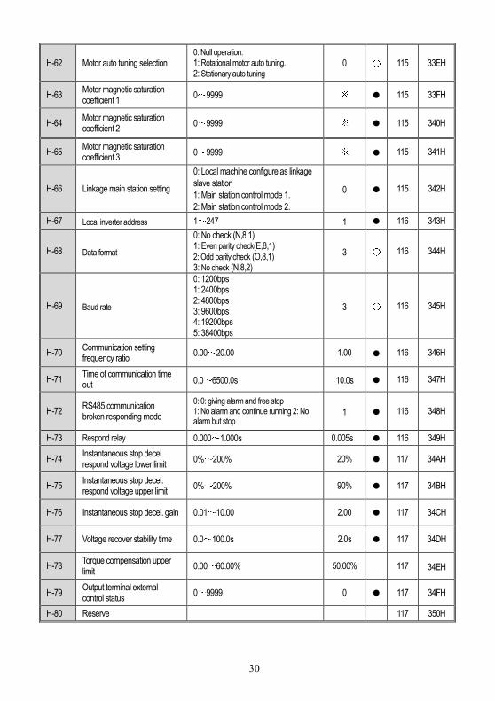
H-62 Motor auto tuning selection 0: Null operation.
1: Rotational motor auto tuning. 2: Stationary auto tuning
0 〇 115 33EH
H-63 Motor magnetic saturation coefficient 1
0~9999 ※ 115 33FH
H-64 Motor magnetic saturation coefficient 2
0~9999 ※ 115 340H
H-65 Motor magnetic saturation coefficient 3
0~9999 ※ 115 341H
H-66 Linkage main station setting
0: Local machine configure as linkage
slave station
1: Main station control mode 1.
2: Main station control mode 2.
0 115 342H
H-67 Local inverter address 1~247 1 116 343H
H-68 Data format
0: No check (N,8,1) 1: Even parity check(E,8,1) 2: Odd parity check (O,8,1) 3: No check (N,8,2)
3 〇 116 344H
H-69 Baud rate
0: 1200bps 1: 2400bps 2: 4800bps 3: 9600bps 4: 19200bps 5: 38400bps
3 〇 116 345H
H-70 Communication setting frequency ratio
0.00~20.00 1.00 116 346H
H-71 Time of communication time out 0.0~6500.0s 10.0s 116 347H
H-72 RS485 communication broken responding mode
0: 0: giving alarm and free stop 1: No alarm and continue running 2: No alarm but stop
1 116 348H
H-73 Respond relay 0.000~1.000s 0.005s 116 349H
H-74 Instantaneous stop decel. respond voltage lower limit
0%~200% 20% 117 34AH
H-75 Instantaneous stop decel. respond voltage upper limit
0%~200% 90% 117 34BH
H-76 Instantaneous stop decel. gain 0.01~10.00 2.00 117 34CH
H-77 Voltage recover stability time 0.0~100.0s 2.0s 117 34DH
H-78 Torque compensation upper limit
0.00~60.00% 50.00% 117 34EH
H-79 Output terminal external control status
0~9999 0 117 34FH
H-80 Reserve 117 350H

31
Chapter 5: Fault Information and Troubleshooting
Keyboard
display
Fault
code Fault type Possible causes Treatment
L.U.1 Too low voltae
while stop
Power supply is too low Voltage detection circuit is
abnormal
Check input power,clear fault. Seek support from factory.
E.LU2 Too low
voltage in run
Power supply is too low Power capacitance is too
small, or there is big impact
current in the power grid. Inner DC main contactor is not
connect well
Check input power,clear fault. Improve power supply. Seek support from factory.
E.oU1 Accel.
over-voltage
Power voltage fluctuation over
limit. Start when motor is running .
Detect power voltage and
clear fault. Restart motor until it
completely stop.Set F1.00 as
1or2.
E.oU2 Decel.
over-voltage
Deceleration time is too short. Load potential energy or
inertia is too large. Power voltage fluctuation over
limit.
Prolong Deceleration time. Reduce load inertia or
improve inverter capacitance or
add braking unit. Detect power voltage and
clear fault.
E.oU3
Constant
speedover-volt
age
Power voltage fluctuation over
limit.
Detect power voltage and
clear fault. Install input reactor.
E.oU4
Over-voltage
while stop
Power voltage fluctuation over
limit.
Check input power,clear fault. Seek support from factory.
E.oC1 Accel.
over-current
Acceleration time is too short. Start running motor. V/F curve setting is not
suitable.Or torque boost too high. Inverter capacitance is too
small.
Prolong acc time. Restart motor until it totally
stop.Set F1.00 as 1or2. Reset V/F curve or torque
boost value. Select inverter with right
capacitance.
E.oC2 Decel.
over-current
Deceleration time is too short. Load potential energy or
inertia is too large. Power voltage fluctuation over
limit.
Prolong Deceleration time. Connect external braking
resistance or braking unit. Select inverter with right
capacitance.
E.oC3 Constant Sudden load change. Check load change and clear

32
speedover-cur
rent
Power grid voltage is too low. it. Check input power,clear fault.
E.oL1 Motor
over-load
V/F curve setting is not
suitable. Or torque boost too high. Power grid voltage is too low. incorrect overload protection
setting. Locked-rotor run or too heavy
load. Universal motor long time low
speed run.
Reset V/F curve or torque
boost value. Check input power,clear fault. Unreasonable F5.06 setting. Adjust load or select inverter
with right capacitance. If need long time low speed
run,please choose special motor
for inverter.
E.oL2 Inverter
over-load
Load is too heavy. Acceleration time is too short. Start running motor. V/F curve setting is not
suitable.Or torque boost too high.
Select inverter with right
capacitance. Prolong acceleration time Restart motor until it totally
stop.Set F1.00 as 1or2.
Reset V/F curve or torque
boost value.
E. SC System
abnormality
Acceleration time is too short. Short circuit between inverter
output phases or earth. Module is damaged. Electromagnetic disturb.
Prolong acceleration time. Check periphery equipments
and restart afrer fault cleared. Seek support from factory. Check system wiring, earth,
shield and deal as required.
E.oH Inverter
over-heat
Temperature is too high. Air channel is blocked. Fan connection parts is
loose. Fan is damaged. Temperature detection circuit
fault
Make the environment
meeting the requirement. Clear the air channel. Check and re-connect the
wire Change the same new fan. Seek support from factory.
E.TE1 Motor static
detection fault
Detection overtime Perform static detection while
motor is running. Capacitance difference is too
big between motor and inverter. Motor parameter setting
mistake.
Check motor connection
wire. Detect after motor stop totally. Change inverter model. Reset parameter according
to nameplate.
E.TE2 Moror rotation
detection fault
Detect while motor is running. Detect with load. Detection overtime Capacitance difference is too
big between motor and inverter. Motor parameter setting
mistake.
Detect after motor stop totally. Re-detect without load. Check motor connection
wire. Change inverter model. Reset parameter according
to nameplate.

33
93SE Memory fault
Electromagnetic disturb in
memory period. EEPROM damage.
re-input and save. Seek support from factory.
LIFE Reserved Seek support from factory.
ERR1
Input phase
missing 3 input phase missing
Check 3phase input power
and phase. Check 3phase input power
wiring.
ERR2
Output phase
missing
3 phase output of inverter
missing connection with motor
Check wire between inverter
and motor, earth and motor
insulation.
ERR3
Current
detection fault
Detect circuit fault. Phase imbalance
Seek for technic support. Check motor and wiring.
ERR4
Inverter
external fault
Peripheral equipment fault
protection. Check peripheral equipment.
ERR5
Swing
frequency fault
User not set right swing
frequency running parameter. Set parameter again.
ERR6
Keyboard
connect fault
Keyboard wire fault. Keyboard component
damage.
Check keyboard wire Seek support from factory.
E.CPE
Parameter
copy fault
Parameter copy
communication is fault. Copy keyboard is not match
the inverter.
Check wire. Select the specified external
keyboard model.
E.CE
RS485
communicatio
n fault
Paut rate not right. Communication connection
not right. Communication format not
right.
Set right Paut rate Check communication wiring Check Communication
format
SEn
Feedback
sensor fault
Alarm while PID analog value
feedback signal is small than
[H-28]. PID feedback wire problem. Feedback sensor problem. Feedback input circuit
problem.
Confirm sensor state,change
it if problem Check wiring. Adjust feedback channel
signal
E.PAn
Keyboard
connect fault
Keyboard wire fault. Keyboard component
damage.
Check keyboard wire Seek support from factory.
E. EF
Inverter
external fault
Peripheral equipment fault
protection. Check peripheral equipment.
E.PAn Keyboard
connect fault
Keyboard wire fault. Keyboard component
damage.
Check keyboard wire Seek support from factory.

34
Chapter 6: Overhaul and Maintenance
During frequency inverter normal operation, except for daily inspections, periodic (such as machine
overhaul or inspections at least every six months as required) inspections must be performed according
to the following table, to preven t trouble before it happens.
Inspectio
n period
Inspecti
on part
Inspection
items Inspection content
Inspection
methods Criteria
At any
time Display
LED
display
If display is abnormal or
not? Vision No abnormal
At any
time
Cooling
system Fan
If there is abnormal
vibration or abnormal
noise.
Visual
examination
and listening
No abnormal
At any
time
Noume
non
Surroundi
ng
environm
ent
Temperature,humidity,dust,harmful gas
Visual
examination , smelling,feeling
By 2-1 term
At any
time
Input
terminal Voltage
If input, output voltage is
abnormal
Detect R、S、T
and U、V、W
terminal
according to the
standards
regulation
periodic Main
circuit
panorama
If the fastener loosen ,
whether having the hot
shot trail , whether
having discharging or
not phenomenon , dust
are too much, if the
wind way is blocked up
Visual,,tighten,clean
No abnormal
Electrolitic
capacitor If surface is abnormal Visual No abnormal
Wire
conductiv
e bar
Whether loosen Visual No abnormal
Terminal Whether the bolt or
screw loosen tighten No abnormal
During the examination, not allowed to dismantle or rock a component for no reason, even pull off a
connector assembly. Otherwise, it can not run or enter malfunction display state. And it will bring faults
of the component,even damage the host switch component IGBT module. When needing
measurement, user should pay attention to various different meters which may reach very different
measurement results. Pointer voltmeter is recommended to use to measure input voltage. Rectifier
voltmeter is recommended to use to measure output voltage. Pliers galvanometer is recommended to
use to measure input and output current. And electrodynamics wattmeter is recommended to use to
measure power.

35
If the frequency inverter is not in use immediately after purchased, and need to be temporarily stored
or long-term stored up, pls obey belowing rules:
1 Frequency inverter should be stored in the place with standard temperature range、 fine ventilation
and no humidity、 dust or metal dust.
2 If frequency inverter has not been put into use yet for more than 1 year, user should carry on
charging testing to restore the characteristic of the inner main circuit filter capacitor. During charging,
user can use the pressure regulator to elevate slowly the input voltage of the frequency inverter to the
rated input voltage. The charging time should be above 1-2 hours. At least test once every year as
narrated above.
3 Frequency inverters are not allowed to be carried out the pressure testing, otherwise, it will lead to
frequency inverter life lessening or damage. Before the insulation testing, user should use 500 MΩvolt
megger measures the frequency inverter. Its insulation resistance should not smaller than 4MΩ
When using the general ohmmeters to measure current, the current in the input end will has imbalance
phenomenon. Generally the difference within 50% is regular. If using general multimeter to measure
the output three-phase voltage, due to being limited by the carry wave frequency disturbance and
multimeter frequency response, the read data, which maybe inaccurate,can be for reference only.
In order to guarantee the frequency inverter stable operation, except for periodic maintenance, the
inner component which bears long-term mechanical wear should be periodic replaced---including the
cooling fan、 main circuit filter capacitor for energy caching and exchange、printed circuit board. In
general continuous using, users can replace them according to below regulation. Also should
according to the concrete conditions such as the usage environment、load condition and frequency
inverter current situation.
Component name Replace year criteria
Cooling fan 2—3 year
Filter capacitor 4—5 year
printed circuit board 8—10 year

36
Chapter 7: Quality Guarantee
This product quality guarantee is processed as the follows items:
Users can enjoy the following “three guarantee” service from the day of buying products if
meeting products quality problem:
1 We guarantee for repair, return and replacement for one month after delivery;
2 We guarantee for repair and replacement for two months after delivery;
3 We guarantee for repair for three months after delivery;
4 When product is exported to abroad, we guarantee for repair for three months after reaching
customer.
No matter where you purchase products, you can enjoy lifelong paid service.
The agency, dealer, provider can provide “three guarantee” service after being authorized by
our company.
When quality problem appears, our company only undertakes “three guarantee” service as
the 11.1 and 11.2 responsibilities above. If user needs more responsibility guarantee, please
insure the product by cooperation with the insurance company.
The malfunctions, caused by the reasons mentioned as below, can only enjoy the paid service
even if the product under warranty,
1 The malfunctions caused by misoperations which are not in compliance with this user manual;
2 The malfunctions caused by unauthorized transform or over-range operation.
3 User has not paid off the payment according to the contract;;
4 The malfunctions caused by the earthquake, fire, flood, lightning, or abnormal voltage, etc;
As for the “three guarantee” service, the product must be returned back to our company and
can only be replaced or mend after responsibility belonging confirmed.

37
Appendix
1.Monitor inquiry
Select this function to enter monitoring menu(group C parameters),and inquire each state
parameters of the frequency inverter. In the monitoring state, you can long press (1 second) PRG key
and directly enter the state of the group C parameters which namely is the state monitoring.
Monitoring
code Content Units
Communication
code
C-1 Given frequency 0.01HZ C01H
C-2 Output frequency 0.01HZ C02H
C-3 Output current 0.1A C03H
C-4 Input voltage V C04H
C-5 Output voltage V C05H
C-6 Mechanical speed RPM C06H
C-7 PID given quantitative % C07H
C-8 PID feedback quantitative % C08H
C-9 Module temperature C09H
C-10 Accumulative operation time hour C0AH
C-11 Accumulative operation time after latest power on Min C0BH
C-12 Output current percentage % C0CH
C-13 Step operation remainder time percentage % C0DH
C-14 Input terminals connect/disconnect status See belowing
diagram C0EH
C-15 Input terminals connect/disconnect status See belowing
diagram C0FH
C-16 Terminal VS1 input value 0.1v C10H
C-17 Terminal AS input value 0.1mA C11H
C-18 Terminal VS2 input value 0.1v C12H
C-19 Terminal pulse input value ※ C13H
C-20 Counter record ※ C14H
C-21 DC bus voltage V C15H
C-22 Analog output A01 0.01V C16H
C-23 Frequency/voltage/current outputA02 ※ C17H
C-24 Reserved -- C18H
C-25 Inverter power grade Kw C19H

38
C-26 Inverter rated voltage V C1AH
C-27 Inverter rated current 0.1A C1BH
C-28 Software version ※ C1CH
Input terminal connect/disconnect state schematic diagram
X5 terminal stage X6 terminal stage FWD terminal stage REV terminal stage X2 terminal stageinput terminal on input terminal offinput terminal on/off state
X1 terminal stageX3 terminal stage X4 terminal stage
Output terminal connect/disconnect state schematic diagram
ReserveReserveReserveReserveY2 terminal stage Y1 terminal stageTA、TB、TCTerminal stageReserve output terminal on output terminal off outputterminal on/off state
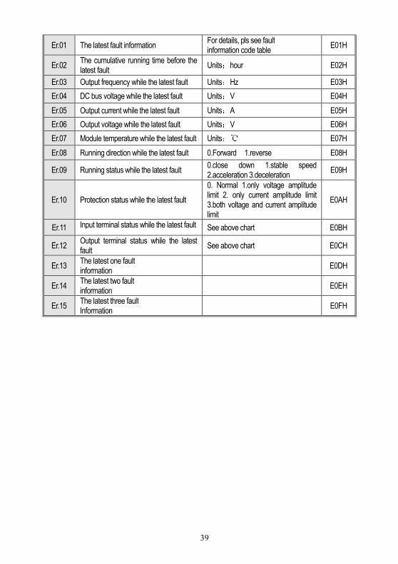
2.Fault information inquiry
After inquiry setting, can set LED display below information circularly by the keyboard up/down keys.
Serial number
Definition Remark
Com
mun
icat
io
n co
de
39
Er.01 The latest fault information For details, pls see fault information code table
E01H
Er.02 The cumulative running time before the latest fault
Units:hour E02H
Er.03 Output frequency while the latest fault Units:Hz E03H
Er.04 DC bus voltage while the latest fault Units:V E04H
Er.05 Output current while the latest fault Units:A E05H
Er.06 Output voltage while the latest fault Units:V E06H
Er.07 Module temperature while the latest fault Units: E07H
Er.08 Running direction while the latest fault 0.Forward 1.reverse E08H
Er.09 Running status while the latest fault 0.close down 1.stable speed 2.acceleration 3.deceleration
E09H
Er.10 Protection status while the latest fault
0. Normal 1.only voltage amplitude limit 2. only current amplitude limit 3.both voltage and current amplitude limit
E0AH
Er.11 Input terminal status while the latest fault See above chart E0BH
Er.12 Output terminal status while the latest fault
See above chart E0CH
Er.13 The latest one fault information
E0DH
Er.14 The latest two fault information
E0EH
Er.15 The latest three fault Information
E0FH