ac21-99 - aircraft wiring and bonding
TRANSCRIPT

AC 21-99 Aircraft Wiring and Bonding Sect 2 Chap 4
1
SECTION 2
CHAPTER 4
ELECTRICAL WIRING INSTALLATION
INTRODUCTION
1. This chapter describes recommended
procedures for installing electrical wiring and
related accessories in ADF aircraft.
REFERENCE SPECIFICATIONS
2. The following specifications are applicable to
electrical wiring installation:
AN742 Clamp, Loop, Plain, Support,
Aircraft
AN936 Washer, Tooth Lock
AN960 Washer Flat
MIL-DTL-23053 Insulation, Sleeving,
Electrical, Heat Shrinkable
MIL-DTL-25038 Wire, Electrical, High-
Temperature, Fire Resistant
and Flight Critical
MIL-DTL-5593 Hose, Aircraft, Low-
Pressure, Flexible
MIL-DTL-8777 Wire Electrical, Silicone
Insulated, Copper, 600-Volt,
200 C
MIL-DTL-8794 Hose, Elastomeric -
Hydraulic Fluid, Oil and Fuel
Resistant
MIL-I-631 Insulation, Electrical,
Synthetic- Resin
Composition, Non-rigid
MIL-K-81786 Kit, Maintenance, Electrical-
Electronic, Cable and Cable
Harness
MIL-PRF-46846 Rubber, Synthetic, Heat
Shrinkable
MIL-PRF-8516 Sealing Compound,
Polysulfide Rubber, Electric
Connectors and Electric
Systems, Chemically Cured
MIL-T-81714 Terminal Junction Systems
Environment Resistant
MIL-W-22759 Wire, Electric, Fluoropolymer
Insulated, Copper or Copper
Alloy
MIL-W-81044 Wire, Electric, Crosslinked
Polyalkene, Crosslinked
Alkane-imide Polymer, or
Polyarylene Insulated, Copper
or Copper Alloy
MS18029 Cover Assembly, Electrical,
For MS27212 Terminal Board
Assembly
MS21919 Clamp. Cushioned, Support,
Loop-Type, Aircraft
MS25036 Terminal, Lug, Crimp Style,
Copper, Insulated, Ring-
Tongue, Bell Mouthed, Type
II, Class 1
MS25274 Cap, Electrical Wire End,
Crimp Style, Type II, Class 1
MS25435 Terminal, Lug, Crimp Style,
Straight Type for Aluminium
Aircraft Wire, Class 1
MS3373 Strip, Mounting, Nut
Insulating, for MS27212
Terminal Board
MS35489 Grommet, Synthetic and
Silicone Rubber, Hot Oil and
Coolant Resistant
MS51957 Screw, Machine-Pan Head,
Cross-Recessed, Corrosion
Resisting Steel, UNC-2A
NAS1070 Washer, Plain, Oversize for
Aluminium Terminals
NASM21042 Nut, Self-Locking, 450 F,
Reduced Hexagon, Reduced
Height, Ring Base , Non-
corrosion Resistant Steel
NASM21266 Grommet, Plastic, Edging
NASM22529 Grommet, Edging
NASM25440 Washer For Use with Aircraft.
Aluminium Terminals
NASM35338 Washer, Lock-Spring, Helical,
Regular Medium Series
NASM35649 Nut, Plain, Hexagon Machine
Screw, UNC-2B
NASM35650 Nut, Plain, Hexagon, Machine
Screw, UNF-2B
NASM961 Washer, Flat, Electrical
NEMA WC27500 Standard for Aerospace and
Industrial Electrical Cable
SAE AS25281 Clamp, Loop, Plastic, Wire
Support
SAE AS27212 Terminal Board. Assembly,
Moulded-In Stud, Electric
SAE AS50881 Wiring, Aerospace Vehicle
SAE AS 6136 Conduit, Electrical, Flexible,
Shielded, Aluminium Alloy for
Aircraft Installation
MIL-I-7444 Insulation Sleeving,
Electrical, Flexible
SAE AS735 Clamp, Loop-Type, Bonding
DEFINITIONS

AC 21-99 Aircraft Wiring and Bonding Sect 2 Chap 4
2
3. The following definitions are applicable to
electrical wiring installation:
a. Open Wiring. Any wire, wire group, or
wire bundle not enclosed in a covering.
b. Wire Group. Two or more wires tied
together to retain identity of the group.
c. Wire Bundle. Two or more wire groups,
tied together because they are going in
the same direction at the point where the
tie is located.
d. Wire Harness. Wire group or bundle
tied together as a compact unit (open
harness) or contained in an outer jacket
(enclosed harness). Wire harnesses are
usually prefabricated and installed in the
aircraft as a single assembly.
e. Electrically Protected Wiring. Those
wires which have protection against
overloading, through fuses, circuit
breakers, or other current-limiting
devices.
f. Electrically Unprotected Wiring. Those
wires (generally from generators to main
buss distribution points) which do not
have protection from fuses, circuit
breakers or other current-limiting
devices.
WIRE TYPES
4. The wires most commonly used in aircraft
electrical systems are in accordance with the
specifications listed in Table 4–1. See Section 2,
Chapter 1, for details of conductor, insulation, voltage
and temperature.
WIRE GROUPS AND BUNDLES
Wire Separation
5. Specification SAE AS50881 restricts the
grouping or bundling of certain wires, such as
electrically unprotected power wiring, and wiring to
duplicate vital equipment. Do not add such wires to
existing bundles unless specifically authorised.
Size of Wire Bundle
6. Wiring specifications generally limit the size of
wire bundles to 5 cm diameter.
Figure 4–1 Group and Bundle Ties
Identity of Groups Within Bundles
7. When several wires are grouped at junction
boxes, terminal boards, panels, etc., retain the identity
of the group within a bundle by spot ties, as shown in
Figure 4–1.
Combing Wires
8. Comb out all wires, except those listed in
paragraph 9, so that wires will be parallel to each other
in a group or bundle.
Twisting Wires
9. When specified on applicable engineering
drawings, twist together the following wires:
a. Wiring in vicinity of magnetic compass
or flux valve.
b. Three-phase distribution wiring.
c. Other wires (usually sensitive circuit
avionic wiring) as specified on
engineering drawings.
10. Twist wires so they lie snugly against each
other, making approximately the number of twists given
in Table 4–2. Check wire insulation for damage after
twisting. If insulation is torn or frayed, replace the wire.
Table 4–1 Wire Types
600 Volts or Under
General Purpose Aluminium High Temperature Fire Resistant
MIL-W-22759 N/A MIL-DTL-8777 *MIL-W-22759
MIL-DTL-25038
Cable, Shielded and Jacketed
NEMA WC27500
*MIL-W-22759 covers wire rated at 600 volts and 1000 volts
Table 4–2 Twists Per 30cm
AC 21-99 Aircraft Wiring and Bonding Sect 2 Chap 4
3
Wire Size #22 #20 #18 #16 #14 #12 #10 #8 #6 #4
2 Wires 10 10 9 8 7.5 7 6.5 6 5 4
3 Wires 10 10 8.5 7 6.5 6 5.5 5 4 3
Spliced Connection in Bundles
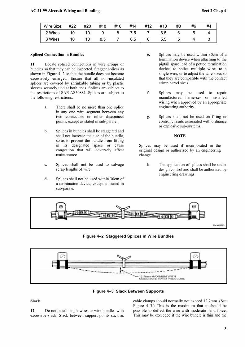
11. Locate spliced connections in wire groups or
bundles so that they can be inspected. Stagger splices as
shown in Figure 4–2 so that the bundle does not become
excessively enlarged. Ensure that all non-insulated
splices are covered by shrinkable tubing or by plastic
sleeves securely tied at both ends. Splices are subject to
the restrictions of SAE AS50881. Splices are subject to
the following restrictions:
a. There shall be no more than one splice
in any one wire segment between any
two connectors or other disconnect
points, except as stated in sub-para e.
b. Splices in bundles shall be staggered and
shall not increase the size of the bundle,
so as to prevent the bundle from fitting
in its designated space or cause
congestion that will adversely affect
maintenance.
c. Splices shall not be used to salvage
scrap lengths of wire.
d. Splices shall not be used within 30cm of
a termination device, except as stated in
sub-para e.
e. Splices may be used within 30cm of a
termination device when attaching to the
pigtail spare lead of a potted termination
device, to splice multiple wires to a
single wire, or to adjust the wire sizes so
that they are compatible with the contact
crimp barrel sizes.
f. Splices may be used to repair
manufactured harnesses or installed
wiring when approved by an appropriate
engineering authority.
g. Splices shall not be used on firing or
control circuits associated with ordnance
or explosive sub-systems.
NOTE
Splices may be used if incorporated in the
original design or authorized by an engineering
change.
h. The application of splices shall be under
design control and shall be authorized by
engineering drawings.
Figure 4–2 Staggered Splices in Wire Bundles
Figure 4–3 Slack Between Supports
Slack
12. Do not install single wires or wire bundles with
excessive slack. Slack between support points such as
cable clamps should normally not exceed 12.7mm. (See
Figure 4–3.) This is the maximum that it should be
possible to deflect the wire with moderate hand force.
This may be exceeded if the wire bundle is thin and the

AC 21-99 Aircraft Wiring and Bonding Sect 2 Chap 4
4
clamps are far apart but the slack must never be so great
that the wire bundle can touch any surface against
which it may abrade. Allow a sufficient amount of slack
near each end for any or all of the following:
a. To permit ease of maintenance.
b. To allow replacement of terminals at
least twice.
c. To prevent mechanical strain on the
wires, cables, junctions, and supports.
d. To permit free movement of shock-and-
vibration mounted equipment.
e. To permit shifting of equipment, for
purposes of maintenance, while installed
in the aircraft.
Bend Radii
13. Bend individual wires to a minimum radius of
ten times the outside diameter of the wire, except that at
terminal boards where the wire is suitably supported at
each end of the bend, a minimum radius of three times
the outside diameter of the wire is acceptable. Bend
wire bundles to a minimum radius of ten times the
outside diameter of the largest wire in the bundle.
NEVER BEND COAXIAL CABLE TO A
SMALLER RADIUS THAN SIX TIMES THE
OUTSIDE DIAMETER.
14. When it is not possible to hold the bending
radius of single wires to the above limits, enclose bend
in tight plastic tubing for at least 5cm each side of the
bend.
Figure 4–4 Routing Bundles
ROUTING AND INSTALLATION Drip Loop
15. Where wiring is dressed downward to a
connector, terminal block, panel or junction box, a drip

AC 21-99 Aircraft Wiring and Bonding Sect 2 Chap 4
5
loop shall be provided in the wiring to prevent fluids or
condensation from running into the components.
General Instructions
16. Install wiring so that it is mechanically and
electrically sound, and neat in appearance. Wherever
practicable, route wires and bundles parallel with, or at
right angles to, the stringers or ribs of the area involved,
as shown in Figure 4–4.
NOTE
Route coaxial cable as directly as possible.
Avoid unnecessary bends in coaxial cable.
Locate attachments at each frame rib on runs
along the length of the fuselage, or at each
stiffener on runs through the wings.
General Precautions
17. When installing electrical wiring in aircraft,
observe the following precautions:
a. Do not permit wire or wire bundles to
have moving, frictional contact with any
other object.
b. Do not permit wire or wire bundles to
contact sharp edges of structure, holes,
etc. (Refer to paragraph 20.)
c. Do not use any installation tools other
than those specifically authorized.
d. Do not damage threads of attaching
hardware by over-tightening or cross-
threading.
e. Do not subject wire bundles to sharp
bends during installation. (Refer to
paragraph 13.)
f. Do not allow dirt, chips, loose hardware,
lacing tape scraps, etc., to accumulate in
enclosures or wire bundles.
g. Do not hang tools or personal
belongings on wire bundles.
h. Do not use installed wire bundles or
equipment as footrests, steps, or
handholds.
i. Do not compensate for wires that are too
long by folding wire back on itself and
hiding such folds within bundles.
j. Do not twist or pull wire bundles during
assembly or installation so that pins are
pulled from connectors, or connectors or
wires are otherwise damaged.
k. Do not stretch wires to mate connectors;
allow sufficient slack to permit easy
mating.
l. Do not paint electrical wires, connectors,
switches or other electrical devices.
Support
18. Bind and support wire and wire bundles to
meet the following requirements:
a. Prevent chafing of cables.
b. Secure wires and wire bundles routed
through bulkheads and structural
members.
c. Fasten wires in junction boxes, panels,
and bundles for proper routing and
grouping.
d. Prevent mechanical strain that would
tend to break the conductors and
connections.
e. Prevent arcing or overheated wires from
causing damage to mechanical control
cables.
f. Facilitate re-assembly to equipment and
terminal boards.
g. Prevent interference between wires and
other equipment.
h. Permit replacement or repair of
individual wires without removing the
entire bundle.
i. Prevent excessive movement in areas of
high vibration.
j. Use of mounting plate, P/N TC-92, for
wire bundle support is recommended in
areas where self-clinching cable straps
are used.
Protection
19. Install and route wires and wire bundles to
protect them from the following:
a. Chafing or abrasion.
b. High temperature.
c. Use of wire bundles as handholds,
footrests, or steps, or as support for
personal belongings and equipment.
AC 21-99 Aircraft Wiring and Bonding Sect 2 Chap 4
6
d. Damage by personnel moving within the
aircraft.
e. Damage from cargo stowage or shifting.
f. Damage from battery acid fumes, spray,
or spillage.
g. Damage from solvents and fluids.
h. Abrasion in wheel wells where exposed
to rocks, ice, mud, etc.
Protection Against Chafing
20. Install wires and wire groups so they are
protected against chafing or abrasion in locations where
contact with sharp surfaces or other wires would
damage the insulation. Damage to the insulation may
result in short circuits, malfunction, or inadvertent
operation of equipment. Use approved cable clamps to
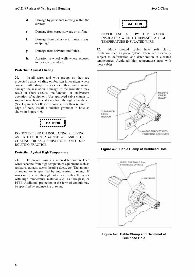
support wire bundles at each hole through a bulkhead.
(See Figure 4–5.) If wires come closer than 6.3mm to
edge of hole, install a suitable grommet in hole as
shown in Figure 4–6.
DO NOT DEPEND ON INSULATING SLEEVING
AS PROTECTION AGAINST ABRASION OR
CHAFING, OR AS A SUBSTITUTE FOR GOOD
ROUTING PRACTICE.
Protection Against High Temperature
21. To prevent wire insulation deterioration, keep
wires separate from high temperature equipment such as
resistors, exhaust stacks, heating ducts, etc. The amount
of separation is specified by engineering drawings. If
wires must be run through hot areas, insulate the wires
with high temperature material such as fibreglass, or
PTFE. Additional protection in the form of conduit may
be specified by engineering drawing.
NEVER USE A LOW TEMPERATURE
INSULATED WIRE TO REPLACE A HIGH
TEMPERATURE INSULATED WIRE.
22. Many coaxial cables have soft plastic
insulation such as polyethylene. These are especially
subject to deformation and deterioration at elevated
temperatures. Avoid all high temperature areas with
these cables.
Figure 4–5 Cable Clamp at Bulkhead Hole
Figure 4–6 Cable Clamp and Grommet at Bulkhead Hole

AC 21-99 Aircraft Wiring and Bonding Sect 2 Chap 4
7
Use of Asbestos in Aircraft
23. In the past asbestos products were used to
protect wire insulation in high temperature areas. This is
no longer considered appropriate due to the well
documented health problems attributed to this material.
Asbestos materials are NOT to be used in aircraft
electrical systems.
24. Where asbestos materials are identified or
suspected in aircraft electrical systems, Environmental
Health personnel should be contacted to provide advice
on appropriate handling procedures. Authorised
engineering personnel should then determine the
feasibility of replacing the asbestos products with
suitable non-asbestos alternatives or, where no
alternatives are available, introducing appropriate risk
management procedures.
Protection Against Personnel and Cargo
25. Install wire bundles so they are protected by
the structure. Use structure or conduit to prevent
pinching against the airframe by cargo. Locate wire
bundles so that personnel are not tempted to use
sections of the wire runs as handholds or ladder rungs.
Protection Against Battery Acids
26. Never route any wires below a battery. Inspect
wires in battery areas frequently. Replace any wires that
are discoloured by battery fumes.
Protection Against Solvents and Fluids
27. Avoid areas where wires will be subjected to
damage from fluids. Wires and cables installed in
aircraft bilges shall be installed at least 15cm from the
aircraft centreline. If there is a possibility that the wire
without a protective outer jacket may be soaked in any
location, use plastic tubing to protect it. This tubing
should extend past the wet area in both directions and be
tied at each end if the wire has a low point between the
tubing ends. The lowest point of the tubing should have
a 3mm drainage hole as shown in Figure 4–7. Punch the
hole in the tubing after the installation is complete and
the low point definitely established. Use a hole punch to
cut a half circle. Be careful not to damage any wires
inside the tubing when using the punch. Tape (non-
adhesive) used as a wrap around the wires and cables
shall also have drainage holes at the low points.
IF IT IS NECESSARY TO MOVE OR REPAIR
WIRES WHICH HAVE A PROTECTIVE
JACKET WITH A DRAINAGE HOLE AT THE
LOW POINT, MAKE SURE DRAINAGE
HOLE IS STILL AT THE LOW POINT
AFTERWARD. IF THE LOCATION OF THE
LOW POINT HAS CHANGED, PUNCH A
NEW HOLE IN THE PROTECTIVE JACKET
AT THE NEW LOW POINT.
Protection in Wheel Wells and Wing Folds
28. Wires located in wheel wells and wing folds
are subject to many additional hazards such as exposure
to fluids, pinching, and severe flexing in service. Make
sure that all wire bundles are protected by sleeves of
flexible tubing securely held at each end. There should
be no relative movement at the point where flexible
tubing is secured. Inspect these wires and the insulating
tubing carefully at very frequent intervals. Replace
wires and/or tubing at the first sign of wear. There
should be no strain on attachments when parts are fully
extended but slack should not be excessive.
Separation from Plumbing Lines
29. When wiring must be routed parallel to
combustible fluid or oxygen lines for short distances,
maintain as much fixed separation as possible, 15cm or
more. Route the wires on a level with, or above, the
plumbing lines. Space clamps so that if a wire is broken
at a clamp it will not contact the line. Where a 15cm
separation is not possible, clamp both the wire bundle
and the plumbing line to the same structure to prevent
any relative motion. If the separation is less than 50mm
but more than 12.7mm, use a nylon sleeve over the wire
bundle to give further protection. Use two cable clamps
back to back, as shown in Figure 4–8, to maintain a
rigid separation only (not for bundle support).
DO NOT ROUTE ANY WIRE SO THAT IT
CAN POSSIBLY COME CLOSER THAN
12.7MM TO A PLUMBING LINE. FACTORY
INSTALLED WIRING WITHIN 12.7MM OF A
FLUID LINE SHOULD BE MOVED WHEN
POSSIBLE. IF MOVING THE WIRING IS
NOT POSSIBLE, THE WIRING SHOULD BE
WRAPPED, TIED, AND CLAMPED TO
MAINTAIN SEPARATION FROM THE
FLUID LINE.
NEVER SUPPORT ANY WIRE OR WIRE
BUNDLE FROM A PLUMBING LINE
CARRYING FLAMMABLE FLUIDS OR
OXYGEN. CLAMPS MAY BE USED ONLY
TO ENSURE SEPARATION.

AC 21-99 Aircraft Wiring and Bonding Sect 2 Chap 4
8
Figure 4–7 Drainage Hole in Low Point of Tubing
Figure 4–8 Separation of Wires From Plumbing Lines
Separation from Control Cables
30. Route wiring to maintain a minimum clearance
of 7.6cm from control cables. If this is not possible,
install mechanical guards to prevent contact of wiring
with control cables.
Installation of EMI Sensitive Wiring
31. Unless engineering justification is provided to
establish alternative procedures, the following
requirements shall be met to reduce the possibility of
EMI:
a. Wires and cables classified as EMI
sensitive may be grouped together in the
same loom, but they shall not be
grouped together with any other wires
and cables.
b. Appropriate clearance (either as far as
practical or as defined by the OEM)
shall be maintained between wires,
cables and looms classified EMI
sensitive and other equipment, wires,
cables and looms.
c. Wires, cables and looms that are EMI
sensitive and are required to cross other
wires, cables or looms, should do so at
right angles, while maintaining the
maximum clearance; and
d. Appropriate levels of EMI protection
(shielding, double-shielding, twisted
pairs etc) should be applied to wire(s)
and looms as required.
32. When aircraft wiring manuals are amended
during the modification process, details of all special
handling instructions for EMI sensitive wires, cables
and looms, including the level of susceptibility,
separation and marking requirements, shall be included.
CONDUIT
Introduction
33. Conduit is used to protect electric wire and
cable from abrasion, corrosive fluids, high temperatures,
RF interference, and damage from cargo handling or
activities of aircraft personnel. Extensive use of conduit
is undesirable because of weight therefore it is used
only in areas where harmful conditions exist, in parts of
aircraft hard to get at for permanent installation, and in
short runs compatible with its protective function.
34. Conduit is available in metallic or non-metallic
(plastic) form. Metallic conduit is either rigid or
flexible; non-metallic conduit is flexible.
METALLIC CONDUIT
Damage Limitations
35. The damage limitations are as follows:
a. Cuts. Cuts are acceptable provided cut
does not extend into the interior of the
conduit.
b. Chafing. Chafing is permissible
provided damage does not extend into
the interior of the conduit, and the
conduit is repositioned to prevent further
chafing.
c. Bends. Bends are acceptable provided
bends do not decrease interior area
sufficiently to prevent freedom of
movement of the wire bundle. Bends
that cause the conduit to interfere with
other parts are unacceptable.
d. Dents. Minor dents are acceptable
provided they do not decrease the
interior area sufficiently to prevent

AC 21-99 Aircraft Wiring and Bonding Sect 2 Chap 4
9
freedom of movement of the wire bundle
throughout the length of the conduit.
36. Metallic conduit is either rigid or flexible. Rigid
metal conduit is aluminium or aluminium alloy tubing.
Aluminium flexible conduit conforms to Specification
SAE AS 6136, which covers two types: Type I - bare
flexible conduit, and Type II - rubber-covered flexible
conduit. Brass flexible conduit conforms to SAE AS
25064. Flexible, aluminium conduit is used only when it
is impracticable to use rigid conduit, such as in areas
where the necessary bends are so complex as to
interfere with installation, or where there is relative
motion between the conduit ends. Flexible brass conduit
is used instead of flexible aluminium in areas where it is
necessary to minimise RF interference, or in areas of
high temperature.
Selection of Conduit Size
37. The protected wire or wire bundle diameter
must not be more than 80% of the inside diameter of the
conduit. (See Figure 4–9)
NOTE
Rigid metallic conduit is supplied in outside
diameter sizes. Subtract twice the wall thickness
to obtain the inside diameter. Flexible metallic
conduit is supplied in inside diameter sizes; no
calculation of diameter is necessary.
38. Determine conduit length to accommodate
length of wire to be installed in conduit between
connections so that when conduit is installed there is no
strain on the wires or ferrules.
Figure 4–9 Capacity Limits for Conduit
Table 4–3 Bend Radii for Rigid Conduit
Nominal Tube OD (mm)
Minimum Bend Radii (mm)
3.1754.756.359.525
12.715.87519.0512.431.7538.144.4550.8
9.52514.27519.0528.57538.147.62557.1576.295.25
114.3133.35152.4
Bending Metallic Conduit
39. Bends in metallic conduit should be kept to a
minium. Table 4–3 provides details of minimum bend
radii.
NON-METALLIC CONDUIT
40. Non-metallic conduit is made of flexible plastic
tubing, conforming to Military Specifications MIL-I-
631 or MIL-I-7444. There is no specification for rigid
non-metallic conduit; phenolic tubing is sometimes
used.
HEAT-SHRINKABLE TUBING
41. In certain applications heat shrinkable tubing
may be an appropriate alternate to flexible conduit.
Details of various types of heat-shrinkable tubing are
listed below.
SAE AMS-DTL-23053/4, Class 2
42. Table 4–4 provides details of SAE AMS-DTL-
23053/4 Insulation Sleeving, Electrical, Heat
Shrinkable, Polyolefin, Dual-Wall, Outer Wall
Crosslinked, Class 2 (Flame Retardant). This sleeving
consists of an outer wall which shrinks and an inner
wall that flows when heated. It is rated from -55 C to
110 C and has a dielectric strength of 500 volts/mil.
Heat shrinkable dual wall sleeving is suitable for one
step potting, encapsulating, or moisture sealing of
electrical components.
SAE AMS DTL-23053/5, Class 1
43. Table 4–5 provides details of SAE AMS-DTL-
23053/5 Insulation Sleeving, Electrical, Heat
Shrinkable, Polyolefin, Flexible, Crosslinked, Class 1
(Flame Resistant). This sleeving is rated from -55 C to
135 C and has a dielectric strength of 500 volts/mil.
Heat shrinkable flexible polyolefin sleeving is suitable
for light duty harness jackets, wire colour coding,
marking or identification.

AC 21-99 Aircraft Wiring and Bonding Sect 2 Chap 4
10
SAE AMS-DTL-23053/8
44. Table 4–6 provides details of SAE AMS-DTL-
23053/8 Insulation Sleeving, Electrical, Heat
Shrinkable, Polyvinylidene Fluoride, Semi-Rigid,
Crosslinked. This sleeving is clear and is rated from -
55 C to 175 C. It has a dielectric strength of 800
volts/mil up to 12.7mm diameter and 600 volts/mil over
12.7mm diameter. Heat shrinkable semi-rigid
polyvinylidene fluoride sleeving is suitable for wire or
termination strain relief.
SAE AMS-DTL-23053/12
45. Table 4–7 provides details of SAE AMS-DTL-
23053/12 Insulation Sleeving, Electrical, Heat
Shrinkable, Polytetrafluoroethylene. This sleeving is
produced in 5 classes (which relate to wall thickness)
and is rated from -67 C to 250 C. It has a dielectric
strength of 800 volts/mil. This sleeving is suitable for
use in areas where resistance to flame and high
temperature is required.
Table 4–4 SAE AMS-DTL-23053/4, Class 2
After Unrestricted Shrinkage Part Number
(Note 1) Minimum Inside
Diameter Expanded (mm)
Minimum Inside Diameter (mm)
Total Wall Thickness (mm)
M23053/4-201-* M23053/4-202-* M23053/4-203-* M23053/4-204-* M23053/4-205-* M23053/4-206-*
6.059.02
12.0718.0924.1336.20
3.184.756.359.53
12.7019.05
0.74 0.13 0.74 0.13 0.76 0.13 0.89 0.13 1.07 0.13 1.19 0.13
Notes:
1. * is replaced with appropriate number to indicate colour. (0-Black, 2-Red, 4-Yellow, 9-White, etc.)
Table 4–5 SAE AMS-DTL-23053/5, Class 1
After Unrestricted Shrinkage Part Number
(Note 1) Minimum Inside
Diameter Expanded (mm)
Minimum Inside Diameter (mm)
Total Wall Thickness (mm)
M23053/5-101-* M23053/5-102-* M23053/5-103-* M23053/5-104-* M23053/5-105-* M23053/5-106-* M23053/5-107-* M23053/5-108-* M23053/5-109-* M23053/5-110-* M23053/5-111-* M23053/5-112-* M23053/5-113-* M23053/5-114-*
1.171.602.363.184.756.359.53
12.7019.0525.4038.1050.8076.2019.60
0.580.791.171.582.363.184.756.359.53
12.7019.0525.4038.1050.80
0.41 0.08 0.43 0.08 0.51 0.08 0.51 0.08 0.51 0.08 0.64 0.08 0.64 0.08 0.64 0.08 0.76 0.08 0.89 0.13 1.02 0.15 1.14 0.18 1.27 0.20 1.40 0.23
Notes:
1. * is replaced with appropriate number to indicate colour. (0-Black, 2-Red, 4-Yellow, 9-White, etc.)

AC 21-99 Aircraft Wiring and Bonding Sect 2 Chap 4
11
Table 4–6 SAE AMS-DTL-23053/8
After Unrestricted Shrinkage Part Number
(Note 1) Minimum Inside
Diameter Expanded(mm)
Minimum Inside Diameter (mm)
Total Wall Thickness (mm)
M23053/8-001-C M23053/8-002-C M23053/8-003-C M23053/8-004-C M23053/8-005-C M23053/8-006-C M23053/8-007-C M23053/8-008-C M23053/8-009-C M23053/8-010-C M23053/8-011-C
1.171.602.363.184.756.359.53
12.7019.0525.4038.10
0.580.791.171.582.363.184.756.359.53
12.7019.05
0.25 0.05 0.25 0.05 0.25 0.05 0.25 0.05 0.25 0.05 0.31 0.08 0.31 0.08 0.31 0.08 0.43 0.08 0.48 0.08 0.51 0.08
Notes:
1. * is replaced with appropriate number to indicate colour. (0-Black, 2-Red, 4-Yellow, 9-White, etc.)
Table 4–7 SAE AMS-DTL-23053/12
After Unrestricted Shrinkage Part Number
(Note 1) Minimum Inside
Diameter Expanded(mm)
Minimum Inside Diameter (mm)
Total Wall Thickness (mm)
Class 1 - Thick Wall
M23053/12-101-* M23053/12-102-* M23053/12-103-* M23053/12-104-* M23053/12-105-* M23053/12-106-* M23053/12-107-* M23053/12-108-* M23053/12-109-* M23053/12-110-* M23053/12-111-* M23053/12-112-* M23053/12-113-*
4.226.358.38
10.5412.6514.7316.9219.0021.0823.2425.429.7233.78
3.304.906.538.139.73
11.3812.9514.5316.1817.7819.4122.6325.91
0.76 0.13 0.76 0.13 0.76 0.13 0.76 0.13 0.76 0.13 0.76 0.15 0.76 0.15 0.76 0.15 0.76 0.15 0.81 0.15 1.01 0.18 1.14 0.18 1.27 0.20

AC 21-99 Aircraft Wiring and Bonding Sect 2 Chap 4
12
After Unrestricted Shrinkage Part Number
(Note 1) Minimum Inside
Diameter Expanded (mm)
Minimum Inside Diameter (mm)
Total Wall Thickness (mm)
Class 2 - Standard Wall
M23053/12-201-* M23053/12-203-* M23053/12-206* M23053/12-208-* M23053/12-212-* M23053/12-216-* M23053/12-220-* M23053/12-224-* M23053/12-227-* M23053/12-230-* M23053/12-232-* M23053/12-233-* M23053/12-234-*
1.271.522.163.054.326.109.40
11.4311.9419.0528.7833.2838.10
0.690.991.371.832.573.585.697.908.54
13.3119.9623.1426.31
0.30 0.05 0.40 0.07 0.40 0.07 0.40 0.07 0.40 0.07 0.51 0.10 0.51 0.10 0.51 0.10 0.64 0.15 0.64 0.15 0.90 0.20 0.90 0.20 0.90 0.20
Class 3 - Thin Wall
M23053/12-301-* M23053/12-303-* M23053/12-306-* M23053/12-308-* M23053/12-312-* M23053/12-316-* M23053/12-320-* M23053/12-324-* M23053/12-327-* M23053/12-330-*
0.861.171.521.933.054.826.109.40
10.9211.94
0.380.560.991.241.832.573.585.697.068.81
0.23 0.05 0.25 0.07 0.30 0.07 0.30 0.07 0.30 0.07 0.30 0.07 0.38 0.10 0.38 0.10 0.38 0.10 0.38 0.10
Class 4 - Very Thin Wall
M23053/12-401-* M23053/12-403-* M23053/12-406-* M23053/12-408-* M23053/12-412-* M23053/12-416-* M23053/12-420-* M23053/12-424-* M23053/12-426-*
1.271.522.162.794.326.109.40
11.4511.94
0.640.971.371.602.513.535.447.658.81
0.15 0.05 0.15 0.05 0.15 0.05 0.15 0.05 0.20 0.05 0.20 0.050.25 0.07 0.25 0.07 0.25 0.07
Class 5 - High Shrink Thin Wall
M23053/12-501-* M23053/12-503-* M23053/12-506-* M23053/12-508-* M23053/12-512-* M23053/12-514-* M23053/12-516-* M23053/12-518-* M23053/12-520-* M23053/12-522-* M23053/12-524-* M23053/12-526-*
1.984.759.53
12.7019.0525.4038.1050.8063.5076.2088.90
101.60
0.641.272.443.665.697.06
10.1613.2016.5119.6922.8626.04
0.23 0.05 0.30 0.05 0.30 0.05 0.38 0.10 0.38 0.10 0.38 0.10 0.38 0.10 0.51 0.13 0.51 0.130.51 0.13 0.51 0.13 0.51 0.13

AC 21-99 Aircraft Wiring and Bonding Sect 2 Chap 4
13
After Unrestricted Shrinkage Part Number
(Note 1) Minimum Inside
Diameter Expanded(mm)
Minimum Inside Diameter (mm)
Total Wall Thickness (mm)
Notes:
1. * is replaced with appropriate number to indicate colour. (0-Black, 2-Red, 4-Yellow, 9-White, etc.)
Use of Heat-Shrinkable Tubing
46. Heat-shrinkable tubing conforming to SAE
AMS-DTL-23053 (except those manufactured from
PVC), may be used to identify, colour code, or strain
relieve wires and wire terminations or for cable
jacketing and repair. The procedure is as follows:
a. Refer to Table 4–4, Table 4–5, Table 4–
6 and Table 4–7 and select a tubing type
and size that conforms to the use
requirements.
b. Position the tubing as required over the
item to be covered.
HEAT GUNS WITH ELECTRIC MOTORS
ARE NOT EXPLOSION PROOF AND ARE
NOT APPROVED FOR USE IN HAZARDOUS
LOCATIONS OR WHERE EXPLOSION
PROOF EQUIPMENT IS REQUIRED.
COMPRESSED AIR/NITROGEN HEAT GUN
M83521/5-01 OR EQUIVALENT ARE THE
ONLY HEAT GUNS THAT MAY BE USED
IN HAZARDOUS LOCATIONS.
HEATING THE HEAT SHRINK TUBING
AND POLYURETHANE INSULATED WIRE
OR CABLES ABOVE 315 C WILL CAUSE
POLYURETHANE COATINGS TO RELEASE
IRRITATING GASES.
c. Use a hot-air gun or compressed air type
heater as a hot air source. Use the
appropriate hot-air reflector on the
nozzle of the heating tool to shrink the
tubing quickly and evenly.
d. Remove the heat as soon as the heat-
shrinkable tubing conforms to the
component being covered. Allow to cool
for 30 seconds before handling.
CABLE CLAMPS
Chloroprene Cushion Clamps
47. The Chloroprene cushion clamps listed in Table
4–8 are intended for general purpose clamping
applications including electrical wire bundle clamping.
A part number example is listed below:
48. Chloroprene cushion clamps are for general
purpose use in areas exposed to petroleum based
hydraulic fluids and occasional fuel splash. They have
excellent ozone resistance however they are not
resistant to phosphate ester based fluids and are not
suitable for use on titanium tubing. Their colour is black
with a blue stripe on both edges.
Table 4–8 Chloroprene Cushion Clamps
PartNumber
InsideDiameter
(mm)Part
Number
InsideDiameter
(mm)
MS21919WDG2 3.18 MS21919WDG16 25.40
MS21919WDG3 4.75 MS21919WDG17 26.97
MS21919WDG4 6.35 MS21919WDG18 28.58
MS21919WDG5 7.92 MS21919WDG19 30.15
MS21919WDG6 9.53 MS21919WDG20 31.75
MS21919WDG7 11.10 MS21919WDG21 33.32
MS21919WDG8 12.70 MS21919WDG24 38.10
MS21919WDG9 14.27 MS21919WDG26 41.28
MS21919WDG10 15.88 MS21919WDG28 44.45
MS21919WDG11 17.45 MS21919WDG30 47.63
MS21919WDG12 19.05 MS21919WDG32 50.80
MS21919WDG13 20.62 MS21919WDG36 57.15
MS21919WDG14 22.22 MS21919WDG40 63.5
MS21919WDG15 23.08 MS21919WDG48 76.2

AC 21-99 Aircraft Wiring and Bonding Sect 2 Chap 4
14
Fluorosilicone Cushion Clamps
49. The Fluorosilicone cushion clamps listed in
Table 4–9 are intended for clamping applications,
including electrical wire bundle clamping, in elevated
temperature, fluid contaminated areas. A part number
example is listed below:
50. Fluorosilicone cushion clamps are for elevated
temperature usage in areas contaminated with petroleum
based fluids. They are unaffected by ozone however
they are not resistant to phosphate ester based fluids.
Their colour is solid blue.
Table 4–9 Fluorosilicone Cushion Clamps
PartNumber
InsideDiameter
(mm)Part
Number
InsideDiameter
(mm)
MS21919WCJ2 3.18 MS21919WCJ16 25.40
MS21919WCJ3 4.75 MS21919WCJ17 26.97
MS21919WCJ4 6.35 MS21919WCJ18 28.58
MS21919WCJ5 7.92 MS21919WCJ19 30.15
MS21919WCJ6 9.53 MS21919WCJ20 31.75
MS21919WCJ7 11.10 MS21919WCJ21 33.32
MS21919WCJ8 12.70 MS21919WCJ24 38.10
MS21919WCJ9 14.27 MS21919WCJ26 41.28
MS21919WCJ10 15.88 MS21919WCJ28 44.45
MS21919WCJ11 17.45 MS21919WCJ30 47.63
MS21919WCJ12 19.05 MS21919WCJ32 50.80
MS21919WCJ13 20.62 MS21919WCJ36 57.15
MS21919WCJ14 22.22 MS21919WCJ40 63.5
MS21919WCJ15 23.08 MS21919WCJ48 76.2
Nitrile Cushion Clamps
51. The Nitrile cushion clamps listed in Table 4–10
are intended for clamping applications, including
electrical wire bundle clamping, in fuel or fuel vapour
areas. A part number example is listed below:
52. Nitrile cushions are for use in fuel immersion
and fuel vapour areas. They have good ozone resistance
however they are not resistant to phosphate ester based
fluids. Not to be used on Titanium tubing. Their colour
is solid yellow.
Table 4–10 Nitrile Cushion Clamps
PartNumber
InsideDiameter
(mm)Part
Number
InsideDiameter
(mm)
MS21919WDF2 3.18 MS21919WDF16 25.40
MS21919WDF3 4.75 MS21919WDF17 26.97
MS21919WDF4 6.35 MS21919WDF18 28.58
MS21919WDF5 7.92 MS21919WDF19 30.15
MS21919WDF6 9.53 MS21919WDF20 31.75
MS21919WDF7 11.10 MS21919WDF21 33.32
MS21919WDF8 12.70 MS21919WDF24 38.10
MS21919WDF9 14.27 MS21919WDF26 41.28
MS21919WDF10 15.88 MS21919WDF28 44.45
MS21919WDF11 17.45 MS21919WDF30 47.63
MS21919WDF12 19.05 MS21919WDF32 50.80
MS21919WDF13 20.62 MS21919WDF36 57.15
MS21919WDF14 22.22 MS21919WDF40 63.5
MS21919WDF15 23.08 MS21919WDF48 76.2
Installation of Cable Clamps
53. Install MS21919 cable clamps as shown in
Figure 4–10. The mounting screw should be above the
wire bundle, if possible. It is also desirable that the back
of the cable clamp rest against a structural member. Use
hardware, as shown in Figure 4–11, to mount cable
clamps to structure. Be careful not to pinch wires in
cable clamp. If the wire bundle is smaller than the
nearest clamp size, or if a clamp of the proper size is not
available, wrap the wire bundle with the necessary
number of turns of insulating tape so that the bundle
will be held securely in the clamp. If the clamp can not
be installed without pinching and/or crushing the wiring
harness, replace the clamp with the next larger clamp
size that will securely hold the harness in place.

AC 21-99 Aircraft Wiring and Bonding Sect 2 Chap 4
15
Figure 4–10 Preferred Angle for Cable Clamps
Figure 4–11 Typical Mounting Hardware for MS21919 Cable Clamps
NOTE
MS21919 cable clamps are cushioned with
insulating material to prevent abrasion of wires.
Never use metal clamps without cushions to hold
wires
54. MS25281 nylon cable clamps may be used to
support wire bundles up to 50mm in diameter in open
wiring, or inside junction boxes and on the back of
instrument panels. When installing nylon cable clamps,
use a large diameter metal washer under the screw head
or nut securing the clamp.
THE PLASTIC STRAP MUST BE CUT FLUSH
WITH THE BOSS SURFACE IN ORDER TO
ELIMINATE PAINFUL CUTS AND
SCRATCHES FROM PROTRUDING STRAP
ENDS.

AC 21-99 Aircraft Wiring and Bonding Sect 2 Chap 4
16
DO NOT USE NYLON CABLE CLAMPS
WHERE THE AMBIENT TEMPERATURE
MAY EXCEED 85 C.
NOTE
MS25281 plastic cable clamps, spaced at
intervals not to exceed 60cm, may be used for
wire support provided every fourth clamp is a
rubber cushion type (MS21919W). The use of
plastic cable clamps on other than horizontal
runs should be avoided unless the installation is
such that slack cannot accumulate between
clamping points.
55. Mount cable clamps directly to “Z” members of
structure. Use angle bracket with two mounting screws
if structural member is angled as shown in Figure 4–12.
56. Where additional clearance is required between
cable and aircraft structure or equipment, a cable clamp
standoff may be used. Suitable standoffs are identified
in Table 4–11.
57. A tool to facilitate the installation of cable
clamps is shown in Figure 4–13; a similar tool
manufactured to Federal Specification GGGP00477 is
available. Similar to conventional multiple slip joint
pliers, the tool compresses and holds the clamp with the
securing bolt in place while a nut is being installed on
the bolt. The tool is particularly useful for installing
clamps in restricted areas and for installing groups of
two or three clamps.
Figure 4–12 Attaching Cable Clamp to Structure
Figure 4–13 Tool for Installing Cable Clamp
Installing Cable Clamps to Tubular Structure
58. Use AN735 clamps without cushions for
clamping to tubular structure. The clamps must fit
tightly but should not deform when locked in place.
Attach wire bundle in MS21919 cable clamp to the
AN735 clamp with AN hardware as shown in Figure 4–
14.
Installing Grommets
59. Military Standard grommets are available in
rubber, nylon, and TFE. Select grommet suitable for the
environmental conditions from Table 4–12. If it is
necessary to cut a nylon grommet in order to install it,
make the cut at an angle of 45 degrees as shown in
Figure 4–15. Cement the grommet in place with general
purpose cement, with the cut at the top of the hole.
When installing caterpillar grommets, cut the grommet
to the required length, making sure to cut square across
the teeth as shown in Figure 4–16. Cement the grommet
in place with general purpose cement, with the cut at the
top of the hole.

AC 21-99 Aircraft Wiring and Bonding Sect 2 Chap 4
17
Figure 4–14 Installing Cable Clamps to Tubular Structure
Table 4–11 Cable Clamp Standoff Identification
Part Number Standoff Length (mm) Thread Size
L35064A2B075 19.6 0.1640-32UNJC (8/32)
L35064A2B100 25.4 0.1640-32UNJC (8/32)
L35064A2B125 31.75 0.1640-32UNJC (8/32)
L35064A2B150 38.10 0.1640-32UNJC (8/32)
L35064A2B175 44.45 0.1640-32UNJC (8/32)
L35064A2B200 50.8 0.1640-32UNJC (8/32)
L35064A2C075 19.6 0.1900-32UNJF (10/32)
L35064A2C100 25.4 0.1900-32UNJF (10/32)
L35064A2C125 31.75 0.1900-32UNJF (10/32)
L35064A2C150 38.10 0.1900-32UNJF (10/32)
L35064A2C175 44.45 0.1900-32UNJF (10/32)
L35064A2C200 50.8 0.1900-32UNJF (10/32)

AC 21-99 Aircraft Wiring and Bonding Sect 2 Chap 4
18
Table 4–12 Grommets - Temperature Limitations of Material
Standard MaterialUpper
Temperature Limit
MS35489 Rubber, Hot Oil & Coolant
Resistant
120 C
MIL-C-22529 & MS21266
Nylon 85 C
MIL-C-22529 & MS21266
TFE 260 C
Figure 4–15 Split Grommet
Figure 4–16 Cutting Caterpillar Grommet
CONNECTIONS TO TERMINAL BOARDS AND BUSBARS
Connecting Terminal Lugs to Terminal Boards
60. Install terminal lugs on MS27212 terminal
boards in such a way that they are locked against
movement in the direction of loosening. (See Figure
4–17.) See Table 4–13 for MS27212 terminal board
specifications, A maximum of four lugs or three lugs
and one bus shall be connected to any one stud.
NOTE
MS27212 terminal boards are used as a
replacement for previously used NAS191 and
MS25123 terminal boards.
Figure 4–17 Connecting Terminal Lugs to Terminal Board

AC 21-99 Aircraft Wiring and Bonding Sect 2 Chap 4
19
Table 4–13 MS27212 Terminal Boards and Covers
Terminal Board MS Part Number
Stud Thread Application Torque Steel
Number of Studs Cover Part Number
MS27212-1-20 6-32UNC-2A 8-10 20 MS18029 - 1(*) - (N)
MS27212-2-16 10-32UNC-2A 20-29 16 MS18029 - 2(*) - (N)
MS27212-3-8 1/4-28UNF-2A 60-70 8 MS18029 – 3(*) - (N)
MS27212-4-8 5/16-24UNF-2A 90-140 8 MS18029 – 4(*) - (N)
MS27212-5-8 3/8-24UNF-2A 115-175 8 MS18029 - 5(*) - (N)
Note: Terminal boards and covers are procured in full lengths with number of studs indicated. Cut to suit needs at installation.
Cover Assembly Part Number
Cover Part Number Type L Type S
StudsMaximum (N)
Nut Assembly Dash No.
Threaded Metal Insert
Retaining Ring Part Number
MS18029 - 1(*) - (N) -11L - (N) - 11S - (N) 20 21 .138-32UNC-2B MS16624-1040
MS18029 - 2(*) - (N) -12L - (N) - 12S - (N) 16 22 .190-32UNC-2B MS16624-1040
MS18029 - 3(*) - (N) -13L - (N) - 13S - (N) 8 23 .250-28UNF-2B MS16624-1062
MS18029 - 4(*) - (N) -13L - (N) - 13S - (N) 8 24 .312-24UNF-2B MS16624-1062
MS18029 - 5(*) - (N) -13L - (N) - 13S - (N) 8 25 .375-24UNF-2B MS16624-1062
MS18029 - 6(*) - (N) -14L - (N) - 14S - (N) 16 26 .164-32UNC-2B MS16624-1040
NOTES: 1. (*) Use letter L or S to indicate type cover desired. (N) Indicates the number of studs in a MS27212 terminal board assembly to be covered.
2. Example of part number: MS18029-2S-16 indicates a cover assembly for a MS27212 terminal board assembly having 16 studs. This cover assembly will consist of the following: 1. MS18029-12S-16 type S cover. 2. MS18029-22 nut assemblies. 3. Part number shall be marked on top of cover.
3. Cover assemblies are not to be used in installations where the temperature exceeds 245 C.
4. A minimum of three threads must be exposed after terminal stacking on the end studs for cover installation.

AC 21-99 Aircraft Wiring and Bonding Sect 2 Chap 4
20
Figure 4–18 Hardware for Wiring Terminal Boards With Copper Terminals
Figure 4–19 Hardware for Wiring Terminal Boards With Aluminium Terminals

AC 21-99 Aircraft Wiring and Bonding Sect 2 Chap 4
21
Figure 4–20 Hardware for Wiring Terminal Boards With Combination of Terminals
Hardware for Wiring Terminal Boards
61. MS25123 terminal boards have studs secured in
place with a AN960 or AN960C flat washer and a
MS35649 or MS35650 steel nut. Place copper terminal
lugs directly on top of the MS35649 or MS35650 nut.
Follow with a AN960 or AN960C flat washer, a
MS35338 split steel lockwasher, and a MS35649 or
MS35650 steel nut; or a AN960 or AN960C flat washer
and a MS21042 self-locking all metal nut.
DO NOT USE AN960D ALUMINIUM
WASHERS.
62. MS27212 terminal boards have studs moulded
in and therefore do not require hardware for attaching
studs to the terminal board. Use same hardware for
installing terminal lugs for MS25123 terminal boards
(refer to paragraph 56 and Figure 4–18). Mounting
screws are insulated with MS3373 insulators when
using MS27212 terminal boards.
63. Place aluminium terminal lugs over a MS25440
or NAS1070 plated flat washer of the correct size for
terminal and stud (see Table 4–14). Follow the terminal
lugs with another MS25440 or NAS1070 flat washer, a
MS35338 split steel lockwasher and either a MS35649
or MS35650 nut or a MS21042 self-locking all metal
nut. See Figure 4–19 for details of this assembly.
DO NOT PLACE ANY WASHER IN THE
CURRENT PATH BETWEEN TWO
ALUMINIUM TERMINAL LUGS OR
BETWEEN TWO COPPER TERMINAL
LUGS.
NEVER PLACE A LOCKWASHER
DIRECTLY AGAINST THE TONGUE OR
PAD OF AN ALUMINIUM TERMINAL OR
BUSBAR.
64. To join a copper terminal lug to an aluminium
terminal lug, place a MS25440 or NAS1070 flat washer
over the nut that holds the stud in place. Follow with the
aluminium terminal lug, another MS25440 washer, the
copper terminal lug, AN960 or AN960C plain washer,
MS35338 split steel lockwasher, and MS35649 or
MS35650 plain nut or MS21042 self-locking nut. See
Figure 4–20 for details.
Table 4–14 Washers for Use with Aluminium Terminal Lugs

AC 21-99 Aircraft Wiring and Bonding Sect 2 Chap 4
22
NAS No. MS No. Terminal Size Stud Size
MS25440-3 8, 6, 4, No. 10
NAS 1070-416 MS25440-4 8, 6, 4, 2, 1, 1/0 6.35mm
NAS 1070-516 MS25440-5 8, 6, 4, 2, 1, 1/0, 2/0 7.92mm
NAS 1070-616 MS25440-6 8, 6, 4, 2, 1, 1/0, 2/0 9.53mm
NAS 1070-716 MS25440-6A 3/0, 4/0 9.53mm
NAS 1070-816 MS25440-8 2, 1, 1/0, 2/0 12.70mm
DO NOT USE AN960D ALUMINIUM
WASHERS.
Installation Torques for Large Copper Terminals
65. Use a torque wrench to tighten nuts on studs
that have a diameter of 9.5mm or larger. This will
provide appropriate pressure to ensure good electrical
contact. The tightening torques for steel studs are as
listed in Table 4–15.
Installation Torques for Aluminium Terminals
66. Use a torque wrench to tighten nuts over any
stack-up containing an aluminium terminal lug. The
tightening torques for aluminium studs are listed in
Table 4–16.
Table 4–15 Installation Torques for Copper Terminals (Inch Pounds of Torque)
Stud Size Plain Nuts Self-locking Nuts
0.375 – 24
0.500 – 20
110 – 120
135 – 150
115 – 125
150 – 170
Table 4–16 Installation Torques for Aluminium Terminals (Inch Pounds of Torque)
Stud Size Nut Torque
No. 10
6.35mm
7.92mm
9.53mm
12.70mm
40
100
135 – 165
220 – 250
440 – 470
Connecting Terminal Lugs to Busbars
67. In order to obtain maximum efficiency in the
transfer of power, the terminal lug and the busbar
should be in direct contact with each other so that the
current does not have to go through any of the attaching
parts, even if these are good current carrying materials.
As illustrated in Figure 4–21 through Figure 4–24, the
above applies whether the terminal lugs and the busbar
are of the same or of different materials.
Cleaning Busbars When Making Connections
68. Clean all busbar areas before making new
connections or replacing old connections. See Section 2,
Chapter 15 for procedure to be followed in cleaning
busbars. The cleaned surface of an aluminium busbar is
coated with a petrolatum-zinc dust compound which is
left on the surface while the connection is made.
Hardware for Connection to Busbars
69. Cadmium plated steel hardware is used to
secure terminals to busbars. Use split lockwashers under
hex nuts and under self-locking nuts. Use plated steel
plain washers between lockwashers and copper
terminals. Use flat washers (MS25440) between
lockwashers and aluminium terminals. As shown in
Figure 4–21 through Figure 4–24, the head of the screw
or bolt can be located on the terminal side or the busbar
side, as required to simplify the installation.
70. Use a cadmium plated steel split lockwasher
MS35338 under the head of every bolt or screw and also
under the nut, as shown in Figure 4–21.
71. Use cadmium plated steel flat washers
(MS25440) in contact with aluminium. The washer
diameter must be at least equal to the tongue diameter of
the terminal. See Table 4–14. Do not select a washer so
large that it will ride on the barrel of the terminal. After
tightening connection, use soft cloth to wipe off excess
petrolatum-zinc compound left in place in accordance
with paragraph 66.
Precautions When Replacing Existing Connections
72. Observe the following precautions when
replacing existing terminal lug connections to busbars:
a. Check all flat washers. Replace bent
washers Replace washers that have
scratched plating or paint on faying
surface.

AC 21-99 Aircraft Wiring and Bonding Sect 2 Chap 4
23
b. Clean busbar connection areas by
approved methods. (See Section 2,
Chapter 15.)
c. Check plated copper terminal lugs
before connecting to an aluminium
busbar. If plating is scratched, replace
terminal lug.
Figure 4–21 Connecting Aluminium Terminal to Aluminium Busbar
Figure 4–22 Connecting Copper Terminal to Aluminium Busbar
Figure 4–23 Connecting Aluminium Terminal to Copper Busbar

AC 21-99 Aircraft Wiring and Bonding Sect 2 Chap 4
24
Figure 4–24 Connecting Copper Terminal to Copper Busbar
Figure 4–25 Connecting Two Terminals to Same Point on Busbar
Connecting Two Terminals to Same Point on Busbar
73. Terminal lugs must always be in direct contact
with busbar. As shown in Figure 4–25, connect one
terminal lug to top of busbar and the other to bottom.
NOTE
Terminal lug offset is positioned so that barrel
cannot contact busbars. This allows proper
seating of tongue on busbar.
Protection of Busbars Against Accidental Shorting
74. Busbars are usually enclosed in panels or
junction boxes to protect them against accidental
shorting. If the busbars are not enclosed, it is desirable
to use some protective coating. A good protective
coating which is easily applied is MIL-PRF-8516
Sealing Compound. This is applied thickly with a
spatula or short bristled brush to the cleaned busbar
prior to assembly of connections. Mask all areas where
connections will be made. Use pressure sensitive tape
for masking. See detailed instructions for applying and

AC 21-99 Aircraft Wiring and Bonding Sect 2 Chap 4
25
curing sealing compound in Section 2, Chapter 11.
Remove masking tape after sealing compound is cured
by cutting into compound next to tape with a razor blade
and peeling tape from the masked area.
75. Busbars can also be protected by slitting a piece
of insulating tubing and wrapping it around the busbar
after all connections are made. Select insulating tubing
which has large enough diameter to permit a generous
overlap when tying it in place. See Figure 4–26 for
cutting and tying details.
DO NOT BEND TERMINAL LUGS TO AN
ANGLE GREATER THAN 90 DEGREES. DO
NOT SUBJECT TERMINAL LUGS TO MORE
THAN ONE BENDING OPERATION.
Connecting Terminal Lugs to Equipment
76. When connecting wired terminal lugs to
terminals on switches, relays, and other equipment, the
terminal lugs may be bent at the barrel tongue junction
if necessary to permit installation. When bending is
required, keep the bend radius as large as possible,
while keeping the bend as small as possible. If
protection from adjacent equipment or personnel is
necessary, exposed terminal lugs may be covered with
an easily removable non-corrosive sealant, such as
RTV3145 or equivalent.
Figure 4–26 Insulating Tubing Around Busbar
INSTALLATION OF WIRES IN CONDUIT
Conduit Capacity
77. Measure the bundle wires before installing in
conduit. In accordance with Specification SAE
AS50881, the bundle diameter must not exceed 80% of
the internal diameter of the conduit. (See Figure 4–27)
NO TIES OR SPLICES ARE PERMITTED
INSIDE A CONDUIT.
Feeding Wires into Conduit
78. Feed wires through a short length of conduit by
taping the end of the bundle together and pushing it
gent1y through. Longer runs of conduit or conduit with
complex bends will require a leader. Make a leader out
of a flannel or other soft cloth patch attached to a string
long enough to pass completely through the conduit.
The patch should fit loosely in conduit. (See Figure 4–
28.) Use compressed air at no more than 240kPa (35psi)
to blow patch and attached string through the conduit.
Tie wire bundle securely to string and tape over junction
to cover all wire ends. Pull string through conduit while
careful1y feeding wires into other end. After wire is
installed, remove tape and detach string.
Supporting Wires at End of Rigid Conduit
79. Use an MS21919 cable clamp to support wires
at each end of conduit. Place the cable clamp in a direct
line with the conduit end to prevent chafing of wires at
end of conduit. Place cable clamp as close to end of
conduit as practicable, but never more than 25cm away.
(See Figure 4–29.)
NOTE
Do not leave wire slack inside conduit. Wires
should be free, but not taut, inside conduit.
Figure 4–27 Conduit Capacity

AC 21-99 Aircraft Wiring and Bonding Sect 2 Chap 4
26
Figure 4–28 Leader for Conduit
Figure 4–29 Support for Wire at Conduit End
INSTALLATION OF CONNECTORS
Assembly of Connectors to Receptacles
80. Assemble connectors to receptacles as follows:
UNLESS OTHERWISE REQUIRED BY
SPECIFIC EQUIPMENT TECHNICAL DATA,
POWER SHOULD BE REMOVED FROM THE
AFFECTED CIRCUIT TO AVOID SHOCK
HAZARD AND POSSIBLE ARCING OF
CONNECTORS.
DO NOT USE EXCESSIVE FORCE TO MATE
CONNECTORS TO RECEPTACLES.
a. Locate the proper position of the plug in
relation to the receptacle by aligning the
key of one part with the groove or
keyway of the other part.
DO NOT TWIST WIRE BUNDLE
EXCESSIVELY TO ACHIEVE PROPER
MATCHING OF PLUG AND RECEPTACLE.
b. Start the plug into the receptacle with a
light forward pressure and engage the
threads of coupling ring and receptacle.
c. Alternately push in the plug and tighten
the coupling ring until the plug is
completely seated.
NEVER USE A TORQUE WRENCH OR
PLIERS TO LOCK COUPLING RINGS.
d. Use a strap wrench or padded conduit
pliers to tighten coupling rings 1/16 to
1/8 turn beyond finger tight if space
around connector is too small to obtain a
good finger grip. Self-locking
connectors are coupled until the
moveable indicator is aligned with index
marks on coupling ring. (See Figure 4–
31.) In fully mated condition locking
indicator shall be aligned within orange
colour band.
NOTE
There shall be no relative movement between
body of connector and coupling ring. This
condition represents a properly seated connector.

AC 21-99 Aircraft Wiring and Bonding Sect 2 Chap 4
27
Disassembly of Connectors from Receptacles
81. Disassemble connectors as follows:
UNLESS OTHERWISE REQUIRED BY
SPECIFIC EQUIPMENT TECHNICAL DATA,
POWER SHOULD BE REMOVED FROM THE
AFFECTED CIRCUIT TO AVOID SHOCK
HAZARD AND POSSIBLE ARCING OF
CONNECTORS.
a. Use a strap wrench or padded pliers to
loosen coupling rings which are too tight
to be loosened by hand.
b. Alternately pull on the plug body and
unscrew coupling ring until connector is
separated.
DO NOT PULL ON ATTACHED WIRES.
c. Protect disconnected plugs and
receptacles with caps to keep debris
from entering and causing faults.
Coding of Connectors
82. As a design objective, receptacles whose plugs
are interchangeable are not located in close proximity to
each other. However, when installation requirements are
such that these receptacles are in adjacent locations, use
clamps on the plug wires or assemble plugs and
receptacles so as to use one of the alternate insert
positions, to make it physically impossible to connect a
plug into the wrong receptacle. Also, colour-code the
connector plug body and the flange or mounting area of
the receptacle.
a. Use one bright colour, such as red,
green, or yellow, for each matching pair.
b. Paint only the shell of plugs - not the
coupling rings.
c. Paint only the mounting flange of the
receptacle.
NOTE
Avoid painting the threaded surfaces or
insulators of plugs or receptacles.
Special Precautions for Connectors with Resilient
Inserts
83. When assembling or installing miniature MS
connectors with resilient inserts, observe the following
special precautions:
a. Before mating connectors, check that
contacts are not splayed or bent. When
mating connectors, make sure that plug
is inserted straight into the receptacle
before tightening coupling ring.
b. Avoid, where possible, locating
connectors of the same shell size
adjacent to each other, whether they
have different insert arrangements or
not.
c. Locate receptacles where they are
clearly visible and accessible to aid in
keying and inserting plug. This will help
to avoid bending receptacle pins while
seeking proper polarization.
d. Position receptacle so large keyway is at
top if mounted vertically or at forward
end if mounted horizontally.
DO NOT MISCONNECT PLUGS AND
RECEPTACLES BY FORCING PINS INTO
THE RESILIENT INSERT, EITHER BY
MISALIGNMENT OF PROPERLY MATING
CONNECTORS OR BY JOINING
CONNECTORS WITH IDENTICAL SHELLS
BUT DIFFERENTLY KEYED INSERT
ARRANGEMENTS.
e. When mating connectors with bayonet
lock coupling, make sure that all locking
rivets of the coupling are engaged.
BE CAREFUL NOT TO LOCK THE PLUG
WHILE COCKED, I.E., TWO LOCKING
RIVETS ENGAGED AND ONE NOT
ENGAGED.
Mounting Connectors
84. Before mounting receptacles to the back of a
panel or bulkhead, make sure there is sufficient
clearance to couple the plug to the receptacle. Make
sure that mounting hardware does not interfere with the
installation of the locking ring.

AC 21-99 Aircraft Wiring and Bonding Sect 2 Chap 4
28
Installing Conduit on Connectors
85. When installing a stepped-down conduit on the
back shell of a connector having large wires (size No. 8
or larger), add an additional back shell to the connector
before installing the conduit. This will allow the wire
bundle to decrease in diameter gradually and prevent
sharp bends in the wires. (See Figure 4–30)
Figure 4–30 Installing Conduit on Connector Back Shell
Figure 4–31 Self-Locking Connector
INSTALLATION OF WIRE IN JUNCTION
BOXES
Lacing or Tying in Junction Boxes
86. Wire bundles can be either laced or tied with
spot ties. Lacing and tying procedures are described in
Section 2, Chapter 8.
USE NYLON CABLE STRAPS ON WIRE
BUNDLES CONTAINING COAXIAL CABLE
IN ACCORDANCE WITH SECTION 2,
CHAPTER 7.
Support Inside Junction Boxes
87. Use MS21919 cable clamps to support wires
across hinged doors so that wires will be twisted and not
bent when the door is opened. See Figure 4–32 for
correct and incorrect methods of support.
88. Attach wire bundles to walls of junction box to
prevent chafing or abrasion against terminal studs or
other items in box. Tie up slack (required for terminal
rework) to prevent snagging.
Figure 4–32 Support Inside Junction Box
TERMINAL JUNCTION SYSTEM
89. The MIL-T-81714 terminal junction system is
designed to replace the open, screw type terminal blocks
found in older aircraft. There are two systems
designated, MIL-T-81714, Series I, and MIL-T-81714,
Series II. The Series I system utilizes a pin contact on
the wire. The Series II system utilizes a socket contact
on the wire.
90. The components making up the Series I
terminal junction system are as follows:

AC 21-99 Aircraft Wiring and Bonding Sect 2 Chap 4
29
a. Terminal junction modules:
(1) Feedback type - all connections
made to one side of module. (See
Figure 4–33 and Figure 4–34.)
(2) Feedthrough type - connection
carried through from one side to
the other of the module. (See
Figure 4–37.)
b. Tracks or frames (holders) for modules.
(See Figure 4–33 and Figure 4–37.)
c. Wire splices, removable contact. (See
Figure 4–38 and Figure 4–39.)
91. The components making up the Series II
terminal junction system are as follows:
a. Terminal junction modules:
(1) Feedback type - all connections
made to one side of module, non-
electronic and electronic. (See
Figure 4–35.)
(2) Distribution type - different size
contacts bussed together.
(3) Grounding type - all connections
grounded to the panel, stud
mount and flange mount. (See
Figure 4–36.)
b. Wire splices, removable contact, non-
electronic and electronic. (See Figure 4–
38 and Figure 4–39.)
c. Tracks or frames (holders) for modules.
(See Figure 4–35.)
Figure 4–33 Feedback Terminal Junction Assembly Series I

AC 21-99 Aircraft Wiring and Bonding Sect 2 Chap 4
30
Figure 4–34 Feedback Terminal Junction Assembly Series I
Figure 4–35 Feedback Terminal Junction Assembly Series II

AC 21-99 Aircraft Wiring and Bonding Sect 2 Chap 4
31
Figure 4–36 Grounding Junction Assembly Series II
Figure 4–37 Feed-Through Terminal Junction Assembly Series I

AC 21-99 Aircraft Wiring and Bonding Sect 2 Chap 4
32
Figure 4–38 Removable Contacts and Wire Splices Series I
Figure 4–39 Removable Contacts and Wire Splices Series II
Classification
92. Terminal junction modules and spices are class
D.
Class D 200°C max Environmental type,
fluid resistant
All other classes (class A, B and C) are
inactive in favour of class D.
Availability of Terminal Junction System
Components
93. The wire terminal contacts are available in five
sizes for Series I and four sizes for Series II, as listed in
Table 4–18. The tracks are available in two basic types,
feedback and feedthrough, as listed in Table 4–17. The
modules available are feedback, feedthrough,
distribution and grounding. The splices available are
single and double as listed in Table 4–17.
Identification
94. The components of the terminal junction
system are identified in Figure 4–41 for Series I, and
Figure 4–42 for Series II. For actual part number
breakdown see MIL-T-81714 specification sheets.
Installation and Removal of Modules from Tracks
95. Installation and removal of Series I modules
from the tracks is accomplished as follows (See Figure
4–33 , Figure 4–34 and Figure 4–37):
a. Loosen screw in locking clamp and slide
clamp to end of rail containing indexing
marks.
b. Insert module into rail next to locking
clamp, with module indexing indicator
on same side as rail indicator.
NOTE
Modules can be installed in only one position in
rail.
c. Slide module against fixed stop at
opposite end of rail.
d. Install additional modules as required,
sliding them against last previously
installed module.
e. Slide locking clamp against last module
and tighten screw securely.
96. Removal of modules is accomplished by
reversing the procedures given above.
97. Series II modules are individually installed,
retained and removed. The installation of modules in the
track is accomplished as follows (See Figure 4–35 and
Figure 4–40):
a. To insert, press the module into the track
assembly by hand until a definite stop is
felt and an audible click is heard.

AC 21-99 Aircraft Wiring and Bonding Sect 2 Chap 4
33
b. To remove, slide the double-sided tool
(module extraction tool M81714/69)
down the indents of the module to the
maximum depth to unlock the retaining
clips. Holding tightly, remove both tool
and module.
Table 4–17 Component Identification
Series I
Module
Type Size Spec. Sheet
Feedback 22D22201612
M81714/17 M81714/1 M81714/2 M81714/3 M81714/4
Feedthrough 22201612
M81714/6 M81714/7 M81714/8 M81714/9
Splice
Type Size Spec. Sheet
Single All M81714/11
Double All M81714/12
Track
Type Size Spec. Sheet
Feedback All M81714/5
Feedthrough All M81714/10
Series II
Module Feedback
Type Size Spec. Sheet
Non-electrical All M81714/60
Distribution All M81714/61
Electronic All M81714/62
Grounding All M81714/63
Splice
Type Size Spec. Sheet
Single All M81714/65
Double All M81714/66
Track
Type Size Spec. Sheet
Feedback All M81714/67
Table 4–18 Wire Range Accommodations
Series I
MatingSize
WireBarrel
Conductor Size
Insulation O.D.
20 22D 28, 26 24, 22
0.76/1.37
16 22 26, 24 22
0.86/1.52
16 20 24, 22 20
1.02/2.11
14 16 20, 18 16
1.65/2.77
12 12 14, 12 2.46/3.61
Series II
MatingSize
WireBarrel
Conductor Size
Insulation O.D.
22 22 26, 24 22
0.76/1.37
20 20 24, 22 20
0.86/1.52
16 16 20, 18 16
1.02/2.11
12 12 14, 12 1.65/2.77
Figure 4–40 Installation and Removal of Modules

AC 21-99 Aircraft Wiring and Bonding Sect 2 Chap 4
34
Figure 4–41 Components of Terminal Junction System – Series I
Figure 4–42 Components of Terminal Junction System – Series II

AC 21-99 Aircraft Wiring and Bonding Sect 2 Chap 4
35
Table 4–19 Crimping Tools for TJS Terminals
Series I
Contact Crimping Tools ModuleBlock Size
Part No. Bin
Code
MatingEndSize
WireBarrelSize
WireSize
Range Basic
Positioner or
Turret
Contact Ins/Rem
Tools
22D M39029/1-507 507 20 22D 22-28 M22520/2-32 M22520/2-32 M81968/14-01or
MS27534-22Dor
M81969/8-01and
M81969/8-02
22 M39029/1-100 100 16 22 22-26 M22520/2-01 M22520/2-11 M81969/14-10or
MS27534-20
20 M39029/1-101 101 16 20 20-24 M22520/2-01M22520/1-01
M22520/2-11 M22520/1-02
(blue)
M81969/14-10or
MS27534-20
16 M39029/1-102 102 14 16 16-20 M22520/2-01 M22520/1-02 (blue)
M81969/14-03or
MS27534-16
12 M39029/1-103 103 12 12 12-14 M22520/2-01 2520/1-02 (yellow)
M81969/14-04or
MS27534-12
Series I
Contact Crimping Tools ModuleBlock Size
Part No. Bin
Code
MatingEndSize
WireBarrelSize
WireSize
Range Basic
Positioner or
Turret
Contact Ins/Rem
Tools
22 M39029/22-191 191 22 22 22-26 M22520/7-01 M22520/7-11 M81968/16-04
20 M39029/22-192 192 20 20 20-24 M22520/1-01 Daniels No. Th343 (red)
M81969/14-10
16 M39029/22-193 193 16 16 16-20 M22520/1-01 Daniels No. Th343 (blue)
M81969/14-03
12 M39029/22-605 605 12 12 12-14 M22520/1-01 M22520/1-16 M81969/16-03
Crimping of Terminals
98. The terminals are crimped on the wires, using
the appropriate crimping tool as indicated in Table 4–
19. Crimping is accomplished as follows:
a. Burn through the insulation with a hot
wire stripper. Do not remove the
insulation at this point. This will protect
the wire from contamination and the
strands from splaying. Recommended
wire stripping dimensions are as
follows:
Series Contact Size Wire Stripping
Dimensions (mm)
I 20 and 22
16 and 12
3.18 to 3.96
5.54 to 6.35
II 22,20,16
12
5.26 + 0.76
5.72 + 0.51
NOTE
Wires may be stripped by any of the methods
listed in Section 2, Chapter 3.
b. Place the contact into the crimp tool (of
the selected wire size) with the contact
crimp barrel facing up.
AC 21-99 Aircraft Wiring and Bonding Sect 2 Chap 4
36
c. Remove the small piece of burnt
insulation from the wire, taking care not
to pinch the insulation with the finger
nails.
d. Insert the bare wire into the open end of
the contact barrel. Push the wire in until
it bottoms. Squeeze the crimp tool. (The
crimp tool will release the contact only
when the full crimping cycle has been
performed.)
e. Check that the wire is crimped correctly
by looking at the inspection hole on the
side of the contact crimp barrel.
Visibility of the bare wire in the contact
inspection hole indicates that the wire
has been properly inserted.
Insertion and Extraction of Terminals
99. Insertion and extraction of the contacts are
accomplished through use of the applicable tool, see
Table 4–19. All the tools are of the same basic design
but differ in size and all are colour-coded. The tools,
squared at the middle for strength and ease in handling,
have tapered tubes at each end: one for insertion and
one for removal of the contact.
100. Insertion is accomplished as follows:
a. Hold the coloured half of the appropriate
insertion/removal tool between the
thumb and forefinger and lay the wire to
be inserted along the slot, leaving about
12.7mm of wire protruding. Then snap
the wire into the tool. (See Figure 4–43)
b. Pull the wire back through the tool, until
the tip of the tool seats against the
shoulder of the contact.
c. Holding the module block with the
cavities facing you, slowly push the
contact straight in to the cavity.
d. A firm stop will be evident when the
contact is locked in place in the module
block. Then let go of the wire and pull
out the tool.
101. Removal is accomplished as follows:
a. With the module facing you, snap the
white end of the appropriate size double-
ended plastic tool over the wire of the
contact to be removed. (See Figure 4–
44.)
b. Slowly slide the tool along the wire into
the insert cavity until it engages the
contact rear and a positive resistance is
felt. At this time, the contact retaining
fingers are in the unlocked position.
c. Press the wire of the contact to be
removed against the serrations of the
plastic tool and pull both the tool and the
contact wire assembly out.
NOTE
No insertion-extraction tool, whether plastic or
metal, should be subjected to mishandling or left
loose among tools in a toolbox. They should be
stored and carried in a separate container to
prevent being damaged. Their tapered ends in
particular shall be protected when the tool is not
in use. The tips of all tools shall be inspected
prior to use. Tools with broken, cracked, or bent
tips shall not be used.
NOTE
All cavities shall be filled with contacts. Sealing
plugs will be inserted in the cavities in the rear of
all unwired contacts.
Figure 4–43 Contact Insertion in Removable Contact Wire Splices
Figure 4–44 Contact Removal from Removable Contact Wire Splices
Insulation Repair
102. Unless otherwise specified by design or official
directive, wire/cable that has insulation damage, and the
centre conductor itself is not damaged, may be repaired
if approved by authorised engineering officer. Damaged
area must not be in excess of 7.6cm in length, and no
more than two damaged areas in a three foot section.
Repair may be made with a non-adhesive backed tape,
such as those listed in Table 4–20, utilizing the
following procedures:

AC 21-99 Aircraft Wiring and Bonding Sect 2 Chap 4
37
a. Wrap tape around the cable for one
complete turn, beginning 5cm from the
damaged area.
b. Using the same continuous length of
tape, spiral wrap with a 50% overlap,
wrap to a point 5cm past the damaged
area. Terminate by wrapping one
complete turn around the cable then cut
the tape.
c. With nylon lacing string, spot tie both
ends to the tape and at 25mm intervals
over the entire length.
Table 4–20 Insulation Repair Tape
Colour Adhesive Type Specification
Black Self-bonding MIL-I-46852
Red Self-bonding MIL-I-46852
Black Non-adhesive MIL-S-1103GE
NOTE
Silicone rubber tapes shall not be used where they will be exposed to fluids such as jet fuels, hydraulic fluids, engine oils, silicone damping fluid (DC-200), etc. These fluids may cause silicone rubber tapes to swell and/or lose adhesive properties.

AC 21-99 Aircraft Wiring and Bonding Sect 2 Chap 4
38
Blank Page