ac variable frequency drive · ac variable frequency drive upto 1800kw ... allows user to set...
TRANSCRIPT
AC Variable Frequency Drive
UPTO 1800kW(2415HP)
AN ISO 9001 : 2008 COMPANY
BE PROUD
User-Friendly
�
�
The 32-bit High Speed Digital Signal Processor protects the drive against the short circuit or ground faultconditions. User setable over load function protects the load against the over load conditions.
Soft stall current limit reduces the output frequency if the output current exceeds the set level before the drivetrips. Input and Output Phase Loss to prevent loading on the other phases.
Easy to Protect
�
�
The cooling fan, one of the common service parts can be easily removed for replacement.
Total Conductive Time and Total Run Time provides the information about the drive and machine usage for themonitoring of serviceable parts.
Easy to Maintain
�
�
�
�
�
�
�
�
Auxiliary Drive feature allows the user to control two different motors with different HP and control schemes.
Multi-pump control feature allows the control of 5 pumps with single drive which doesn't require PLC.
Built-In energy meter displays all electrical parameters, which eliminates the need of separate energy meter.
50 C (122 F) design, eliminates the need of derating the drive.
Built-in PID, PLC and application specific software reduces the peripherals’ cost.
Built-in energy saving calculator.
Modbus-RTU connectivity offered as a standard.
No option board required for encoder feedback.
º º
Easy to Economize
�
�
The AXPERT-EAZY has been downsized considerably hence require less space to mount.
Well-defined terminations for power and control circuit allows user to install and wire the drive easily. Use ofterminals with captive screws on the main control board facilitates single-handed installation.
Easy to Install & Wire
�
�
�
�
�
80-character, 4-line LCD display & 8-key keypad (HMI)
Self-explanatory full parameter name is displayed on Digital Operation Panel for easy programming. Thisallows user to set parameters without referring to the manual.
Navigation of parameters made easy with self-explanatory functional keys like NORM, MODE, GROUP, UP &DOWN, RUN & STOP for easy operation in local mode.
8 selectable parameters on single screen helps to monitor critical parameters simultaneously.
Fault history with last ten faults and 8 important parameters helps in trouble shooting.
Easy to Operate & Program
�
�
�
�
�
Advanced control is easy and less expensive with configurable analog / digital I/O and integral PID.
Digital Operation Panel can be extended to 300 meter (1000 ft) for remote operation through optional cable.
Easily configurable control modes as per the application requirement.
User programmable 8-analog & 15 digital I/O’s.
drive support software for PC.Axpert Communicator
Easy to Control
1
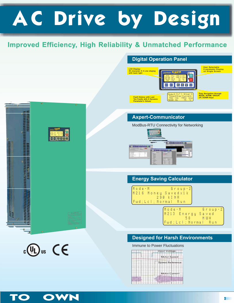
AC Drive by DesignImproved Efficiency, High Reliability & Unmatched Performance
AC Drive by DesignImproved Efficiency, High Reliability & Unmatched Performance
Fault History with LastTen Faults with 8 DynamicParameter's Values
LCD Display:20 character X 4 Line displaywith back light
User Selectable8 parameter Displayon Single Screen
Immune to Power Fluctuations
ModBus-RTU Connectivity for Networking
Digital Operation Panel
Axpert-Communicator
Energy Saving Calculator
Designed for Harsh Environments
F w d ; L c l ; N o r m a l R u n
M o d e - M G r o u p - 2M 2 1 3 E n e r g y S a v e d
5 8 M W H
LMode-M F T - 1 Group- 4Timed Over Current592 Vdc 795.6 Amp
50.00 Hz 75 CO
Eazy Navigation throughMODE, NORM, GROUP,UP, DOWN Keys
pM o d e - M G r o u - 2M 2 1 6 M o n e y S a v e d x 1 k
F w d ; L c l ; N o r m a l R u n2 9 0 I N Rk
2TO OWNTO OWN
Full range of functions for fans and pumps�
�
�
�
�
�
�
�
�
Square law V/F function ensures high energy efficiency.
Built-In PID Control with Sleep Mode and variables can be assigned to real process units.
Speed Search allows the drive to start with rotating machinery without damage or tripping.
Power Loss Carry Through allows the uninterrupted operation of the machine up to 5 second power loss.
Under Current Level to prevent the machine from running idle.
Multi-pump control function.
Built-In Energy Meter
Reverse direction lock to inhibit the reverse direction start
Digital connections accept NPN or PNP (sink/source) to allow the use of existing and new sensors / PLC.
and Energy saving calculator.
3
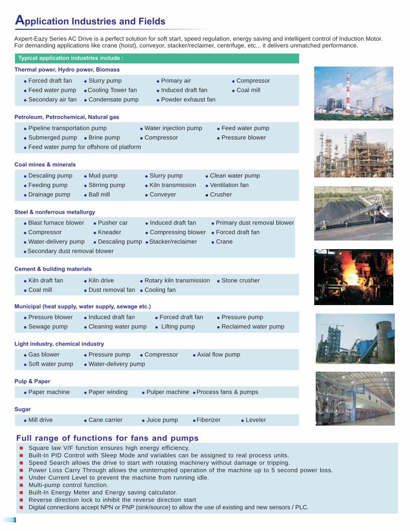
Application Industries and Fields
Axpert-Eazy Series AC Drive is a perfect solution for soft start, speed regulation, energy saving and intelligent control of Induction Motor.For demanding applications like crane (hoist), conveyor, stacker/reclaimer, centrifuge, etc... it delivers unmatched performance.
Typical application industries include :
� � � �
� � � �
� � �
Forced draft fan lurry pump rimary air ompressorS P C
Feed water pump Cooling Tower fan Induced draft fan Coal mill
Secondary air fan Condensate pump Powder exhaust fan
Thermal power, Hydro power, Biomass
� � �
� � � �
�
P W F
Submerged pump Brine pump Compressor Pressure blower
Feed water pump for offshore oil platform
ipeline transportation pump ater injection pump eed water pump
Petroleum, Petrochemical, Natural gas
� � � �
� � � �
� � �
D M S C
Feeding pump Stirring pump Kiln transmission Ventilation fan
Drainage pump Ball mill Conveyer Crusher
escaling pump ud pump lurry pump lean water pump
�
Coal mines & minerals
� � � �
� � � �
� � � �
�
B Pusher car I Primary dust removal blower
Compressor Kneader Compressing blower Forced draft fan
Water-delivery pump Descaling pump Stacker/reclaimer Crane
Secondary dust removal blower
last furnace blower nduced draft fan
Steel & nonferrous metallurgy
� � � �
� � �
K K R Stone crusher
Coal mill Dust removal fan Cooling fan
iln draft fan iln drive otary kiln transmission
Cement & building materials
� � � �
� � � �
P I F P
Sewage pump Cleaning water pump Lifting pump Reclaimed water pump
ressure blower nduced draft fan orced draft fan ressure pump
Municipal (heat supply, water supply, sewage etc.)
� � � �
� �
G P C A
Soft water pump Water-delivery pump
as blower ressure pump ompressor xial flow pump
Light industry, chemical industry
� � � �Paper machine Paper winding Pulper machine Process fans & pumps
Pulp & Paper
� � � � �Mill drive Cane carrier Juice pump Fiberizer Leveler
Sugar
4
STANDARD SPECIFICATIONS
030 037 045 055 075 090 110 132 160 200 250 315 355 400 450 500 630 710 900 10E 12E 14E
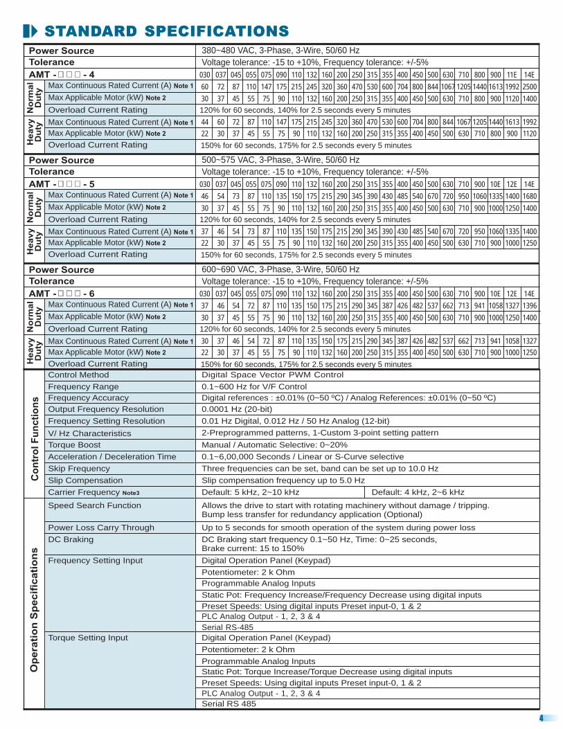
46 54 73 87 110 135 150 175 215 290 345 390 430 485 540 670 720 950 1060 1335 1400 1680
30 37 45 55 75 90 110 132 160 200 250 315 355 400 450 500 630 710 900 1000 1250 1400
37 46 54 73 87 110 135 150 175 215 290 345 390 430 485 540 670 720 950 1060 1335 1400
22 30 37 45 55 75 90 110 132 160 200 250 315 355 400 450 500 630 710 900 1000 1250
120% for 60 seconds, 140% for 2.5 seconds
150% for 60 seconds, 175% for 2.5 seconds
every 5 minutes
every 5 minutes
Power Source
Tolerance
AMT -
500~575 VAC, 3-Phase, 3-Wire, 50/60 Hz
Voltage tolerance: Frequency tolerance: +/-5%-15 to +10%,
No
rmal
Du
tyH
eavy
Du
ty
Max Continuous Rated Current (A) Note 1
Max Applicable Motor (kW) Note 2
Overload Current Rating
Max Continuous Rated Current (A) Note 1
Max Applicable Motor (kW) Note 2
Overload Current Rating
37 46 54 72 87 110 135 150 175 215 290 345 387 426 482 537 662 713 941 1058 1327 1396
30 37 45 55 75 90 110 132 160 200 250 315 355 400 450 500 630 710 900 1000 1250 1400
30 37 46 54 72 87 110 135 150 175 215 290 345 387 426 482 537 662 713 941 1058 1327
22 30 37 45 55 75 90 110 132 160 200 250 315 355 400 450 500 630 710 900 1000 1250
120% for 60 seconds, 140% for 2.5 seconds
150% for 60 seconds, 175% for 2.5 seconds
030 037 045 055 075 090 110 132 160 200 250 315 355 400 450 500 630 710 900 10E 12E 14E
every 5 minutes
every 5 minutes
Power Source
Tolerance
AMT -
600~690 VAC, 3-Phase, 3-Wire, 50/60 Hz
Voltage tolerance: Frequency tolerance: +/-5%-15 to +10%,
No
rmal
Du
tyH
eavy
Du
ty
Max Continuous Rated Current (A) Note 1
Max Applicable Motor (kW) Note 2
Overload Current Rating
Max Continuous Rated Current (A) Note 1
Max Applicable Motor (kW) Note 2
Overload Current Rating
030 037 045 055 075 090 110 132 160 200 250 315 355 400 450 500 630 710 800 900 11E 14E
60 72 87 110 147 175 215 245 320 360 470 530 600 704 800 844 1067 1205 1440 1613 1992 2500
30 37 45 55 75 90 110 132 160 200 250 315 355 400 450 500 630 710 800 900 1120 1400
44 60 72 87 110 147 175 215 245 320 360 530 600 704 800 844 1067 1205 1440 1613 1992
22 30 37 45 55 75 90 110 132 160 200 250 315 355 400 450 500 630 710 800 900 1120
120% for 60 seconds, 140% for 2.5 seconds every 5 minutes
150% for 60 seconds, 175% for 2.5 seconds
470
every 5 minutes
Power Source
Tolerance
AMT -
380~480 VAC, 3-Phase, 3-Wire, 50/60 Hz
Voltage tolerance: , Frequency tolerance: +/-5%-15 to +10%
No
rmal
Du
tyH
eavy
Du
ty
Max Continuous Rated Current (A) Note 1
Max Applicable Motor (kW) Note 2
Overload Current Rating
Max Continuous Rated Current (A) Note 1
Max Applicable Motor (kW) Note 2
Overload Current Rating
- 4
- 5
- 6
Control Method Digital Space Vector PWM Control
Frequency Range 0.1~600 Hz for V/F Control
Output Frequency Resolution 0.0001 Hz (20-bit)
Frequency Setting Resolution
V/ Hz Characteristics
Torque Boost Manual / Automatic Selective: 0~20%
Acceleration / Deceleration Time 0.1~6 00,000 Seconds / Linear or S-Curve selective,
Co
ntr
ol
Fu
nc
tio
ns
2-Preprogrammed patterns, 1-Custom 3-point setting pattern
0.01 Hz Digital, 0.012 Hz / 50 Hz Analog (12-bit)
Frequency Accuracy Digital references : ±0.01% (0~50 ºC) / Analog References: ±0.01% (0~50 ºC)
Skip Frequency Three frequencies can be set, band can be set up to 10.0 Hz
Slip Compensation Slip compensation frequency up to 5.0 Hz
Carrier Frequency Note3 Default: 5 kHz, 2~10 kHz
Power Loss Carry Through Up to 5 seconds for smooth operation of the system during power loss
DC Braking DC Braking start frequency 0.1~50 Hz, Time: 0~25 seconds,Brake current: 15 to 150%
Digital Operation Panel (Keypad)
Preset Speeds: Using digital inputs Preset input-0, 1 & 2
Frequency Setting Input
Potentiometer: 2 k Ohm
Programmable Analog Inputs
Speed Search Function Allows the drive to start with rotating machinery without damage / tripping.Bump less transfer for redundancy application (Optional)
Static Pot: Frequency Increase/Frequency Decrease using digital inputs
PLC Analog Output - 1, 2, 3 & 4
Serial RS-485
Op
era
tio
n S
pe
cif
ica
tio
ns
Preset Speeds: Using digital inputs Preset input-0, 1 & 2
Static Pot: Torque Increase/ Decrease using digital inputsTorque
Digital Operation Panel (Keypad)
Potentiometer: 2 k Ohm
Programmable Analog Inputs
Torque Setting Input
Serial RS 485
PLC Analog Output - 1, 2, 3 & 4
Default: 4 kHz, 2~6 kHz
STANDARD SPECIFICATIONSO
pera
tio
n S
pecif
icati
on
s
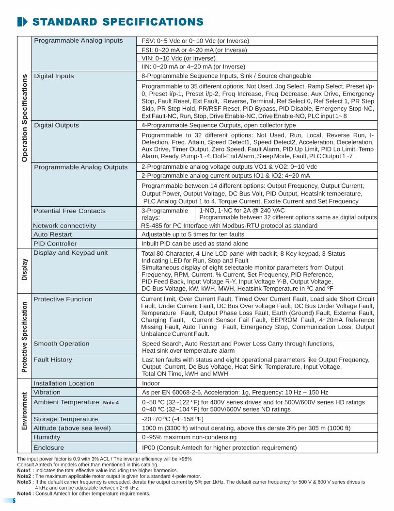
Programmable to 35 different options: Not Used, Jog Select, Ramp Select, Preset i/p-
0, Preset i/p-1, Preset i/p-2, Freq Increase, Freq Decrease, Aux Drive, Emergency
Stop, Fault Reset, Ext Fault, Reverse, Terminal, Ref Select 0, Ref Select 1, PR Step
Skip, PR Step Hold, PR/RSF Reset, PID Bypass, PID Disable, Emergency Stop-NC,
Ext Fault-NC, Run, Stop, Drive Enable-NC, Drive Enable-NO, PLC input 1 8~
FSV: 0~5 Vdc or 0~10 Vdc (or Inverse)
FSI: 0~20 mA or 4~20 mA (or Inverse)
VIN: 0~10 Vdc (or Inverse)
IIN: 0~20 mA or 4~20 mA (or Inverse)
Digital Inputs 8-Programmable Sequence Inputs, Sink / Source changeable
Programmable Analog Inputs
Programmable Analog Outputs
Digital Outputs
Potential Free Contacts 3-Programmablerelays:
1-NO, 1-NC for 2A @ 240 VACProgrammable between 32 different options same as digital outputs
Auto Restart Adjustable up to 5 times for ten faults
PID Controller Inbuilt PID can be used as stand alone
Network connectivity RS-485 for PC Interface with Modbus-RTU protocol as standard
Fault History
Smooth Operation Speed Search, Auto Restart and Power Loss Carry through functions,Heat sink over temperature alarm
Installation Location Indoor
Storage Temperature
Altitude (above sea level)
Humidity
Enclosure
-20~70 ºC (-4~158 ºF)
1000 m (3300 ft) without derating, above this derate 3% per 305 m (1000 ft)
0~95% maximum non-condensing
IP00 (Consult Amtech for higher protection requirement)
Ambient Temperature Note 4 0~50 ºC (32~122 ºF) for 400V series drives and for 500V/600V series HD ratings0~40 ºC (32~104 ºF) for 500V/600V series ND ratings
The input power factor is 0.9 with 3% ACL / The inverter efficiency will be >98%Consult Amtech for models other than mentioned in this catalog.
Indicates the total effective value including the higher harmonics.The maximum applicable motor output is given for a standard 4-pole motor.
Note1 :Note2 :Note3 :
Note4 :
If the default carrier frequency is exceeded, derate the output current by 5% per 1kHz.
Consult Amtech for other temperature requirements.
The default carrier frequency for 500 V & 600 V series drives is4 kHz and can be adjustable between 2~6 kHz.
Pro
tec
tiv
e S
pe
cif
ica
tio
n
Display and Keypad unit Total 80-Character, 4-Line LCD panel with backlit, 8-Key keypad, 3-StatusIndicating LED for Run, Stop and FaultSimultaneous display of eight selectable monitor parameters from OutputFrequency, RPM, Current, % Current, Set Frequency, PID Reference,PID Feed Back, Input Voltage R-Y, Input Voltage Y-B, Output Voltage,DC Bus Voltage, kW, kWH, MWH, Heatsink Temperature in ºC and ºF
Dis
pla
y
Vibration As per EN 60068-2-6, Acceleration: 1g, Frequency: 10 Hz ~ 150 Hz
En
vir
on
me
nt
4-Programmable Sequence Outputs, open collector type
Programmable to 32 different options: Not Used, Run, Local, Reverse Run, I-Detection, Freq. Attain, Speed Detect1, Speed Detect2, Acceleration, Deceleration,Aux Drive, Timer Output, Zero Speed, Fault Alarm, PID Up Limit, PID Lo Limit, TempAlarm, Ready, Pump-1 , Doff-EndAlarm, Sleep Mode, Fault, PLC Output 1 7~4 ~
Last ten faults with status and eight operational parameters like Output Frequency,Output Current, Dc Bus Voltage, Heat Sink Temperature, Input Voltage,Total ON Time, kWH and MWH
Protective Function Current limit, Over Current Fault, Timed Over Current Fault, Load side Short CircuitFault, Under Current Fault, DC Bus Over voltage Fault, DC Bus Under Voltage Fault,Temperature Fault, Output Phase Loss Fault, Earth (Ground) Fault, External Fault,Charging Fault, Current Sensor Fail Fault, EEPROM Fault, 4~20mA ReferenceMissing Fault, Auto Tuning Fault, Emergency Stop, Communication Loss, OutputUnbalance Current Fault.
5
2-Programmable analog voltage outputs VO1 & VO2: 0~10 Vdc
2-Programmable analog current outputs IO1 & IO2: 4~20 mA
Programmable between 14 different options: Output Frequency, Output Current,
Output Power, Output Voltage, DC Bus Volt, PID Output, Heatsink temperature,
PLC Analog Output 1 to 4, Torque Current, Excite Current and Set Frequency

EXTERNAL DIMENSION FOR 400V SERIES
EXTERNAL DIMENSION FOR 500V & 600V SERIES
Dimensions in mm (inch) Weight inkg (lb)A B C D E F G
595(23.4)
291(11.5)
300(11.8)
236.5(9.3)
574.5(22.6)
82.5(3.2)
142.5(5.6)
22(48.5)
679.5(26.7)
290(11.4)
300(11.8)
236.5(9.31)
659.5(26.0)
82.5(3.2)
227.5(9.0)
28.5(62.8)
H
80.5(3.2)
80.5(3.2)
AMT-011-5, AMT-015-5, AMT-018-5, AMT-022-5, AMT-030-5
AMT-011-6, AMT-015-6, AMT-018-6, AMT-022-6, AMT-030-6, AMT-037-6
AMT-037-5, AMT-045-5, AMT-055-5
AMT-045-6, AMT-055-6, AMT-075-6
AMT-075-5, AMT-090-5, AMT-110-5
AMT-090-6, AMT-110-6, AMT-132-6
Consult for the dimensionAMTECH
970(38.2)
360(14.2)
255(10.0)
940(37.0)
127(5.0)
236.5(9.3)
77.4(170.6)
105.5(4.2)
364(14.3)
1247(49.0)
506(19.9)
400(15.7)
1217(47.9)
154.5(6.0)
460(18.1)
117.7(259.4)
224.5(8.8)
321(12.6)
906(35.7)
368.5(14.5)
313(12.3)
876(34.5)
121(4.8)
375(14.8)
65(143.3)
120(4.7)
364.5(14.3)
AMT-132-5, AMT-160-5
AMT-160-6, AMT-200-6
AMT-200-5, AMT-250-5, AMT-315-5
AMT-250-6, AMT-315-6, AMT-355-6
AMT-355-5 ~ AMT-14E-5
AMT-400-6 ~ AMT-14E-6
6
Dimensions in mm (inch) Weight inkg (lb)A B C D E F G
470(18.5)
250(9.8)
262(10.3)
197(7.8)
439(17.3)
61.5(2.4)
81(3.2)
18(39.7)
585(23.0)
250(9.8)
300(11.8)
197(7.8)
565(22.2)
61.5(2.4)
186(7.3)
31(68.3)
H
61.5(2.4)
61.5(2.4)
AMT- 011- 4, AMT- 015- 4, AMT- 018- 4, AMT- 022- 4
AMT-030-4, AMT-037-4, AMT-045-4, AMT-055-4
AMT-075-4, AMT-090-4
970(38.2)
360(14.2)
255(10.0)
940(37.0)
127(5.0)
238(9.4)
76(167.6)
106(4.2)
365(14.4)
1185(46.6)
481(18.9)
400(15.7)
1155(45.5)
167(6.6)
431(17.0)
103(227.0)
187(7.4)
321(12.6)
700(27.6)
322(12.7)
217(8.5)
680(26.8)
98(3.9)
145(5.7)
45(99.2)
98(3.9)
365(14.4)
AMT-110-4, AMT-132-4, AMT-160-4
AMT-200-4, AMT-250-4
AMT-315-4, AMT-355-4
1330(52.4)
506(19.9)
400(15.7)
1300(51.2)
155(6.1)
528(20.8)
138(304.2)
224.5(8.8)
321(12.6)
AMT-400-4 ~ AMT-14E-4
Consult for the dimensionAMTECH
7
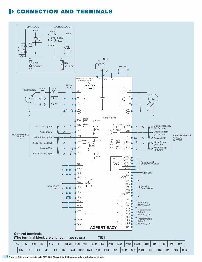
CONNECTION AND TERMINALS
I02FSV
P15
0VFSI V01 0V
IIN0V VIN VO2 I01 PSI2
PSI3CANL STOP +24V PSI1
PSI6CANH RUN COM
PSI5 COM PSO2 PSO4
PSO1PSI4 +24V PSO3 COM
TX COM PBN PAN COM
RX PB +5VPA
Note-1 : This circuit is valid upto AMT 055. Above this, DCL comes before soft charge circuit.
Control terminals(The terminal block are aligned in two rows.) TB1
+24V
COM
PSI1
PSI2
PSI3
PSI4
PSI5
COM
PSI6
STOP
RUN
INPUT
Analog COM
0-10V PID Feedback
4-20mA Analog input
4-20mA Analog Ref
0-10V Analog Ref
Analog COM
FSV
0V
FSI
VIN
0V
IIN
270�
10k�
33k� 270�
940�
10k�
33k�
+15V
ANALOG
Output Current
(0-10V, 1mA)
Analog COM
(4-20mA)
(4-20mA)Motor Voltage
Motor Power
(0-10V, 1mA)Output FrequencyVO1
VO2
0V
IO1
IO2
50�
50�
270�
270�
PROGRAMMABLEANALOGOUTPUT
ProgrammableRelay 2240V AC, 1A
ProgrammableRelay 1240V AC, 1AR1B
R2A
R2C
R2B
R1A
R1C
Fault Relay240V AC, 1A
NC
FB
FC
PB
PBN
PAN
+5VCOM
ConnectionsEncoder
FA
PA
COM
PSO1
PSO2
PSO3
PSO4
COM
Sequence Outputs
RS-485
Programmable
RX
TX
SEQUENCEINPUT
CANH
CANH
Power SupplyMCCB Filter
Noise
E
ACL
L2
L3
E
W
V
L1 U
L+2L+1 L-
DCL
DB UNIT
+24V
SOURCESOURCE
L<50mJP1
COM
SINK
PSI 5.6k�
+24V
JP1
SINK
L<50m
PSI
+24V
5.6k�
SINK LOGIC SOURCE LOGIC
AXPERT-EAZY
Main-circuit block
P15Control block
PROGRAMMABLE
M
Note-1
Soft charge circuit

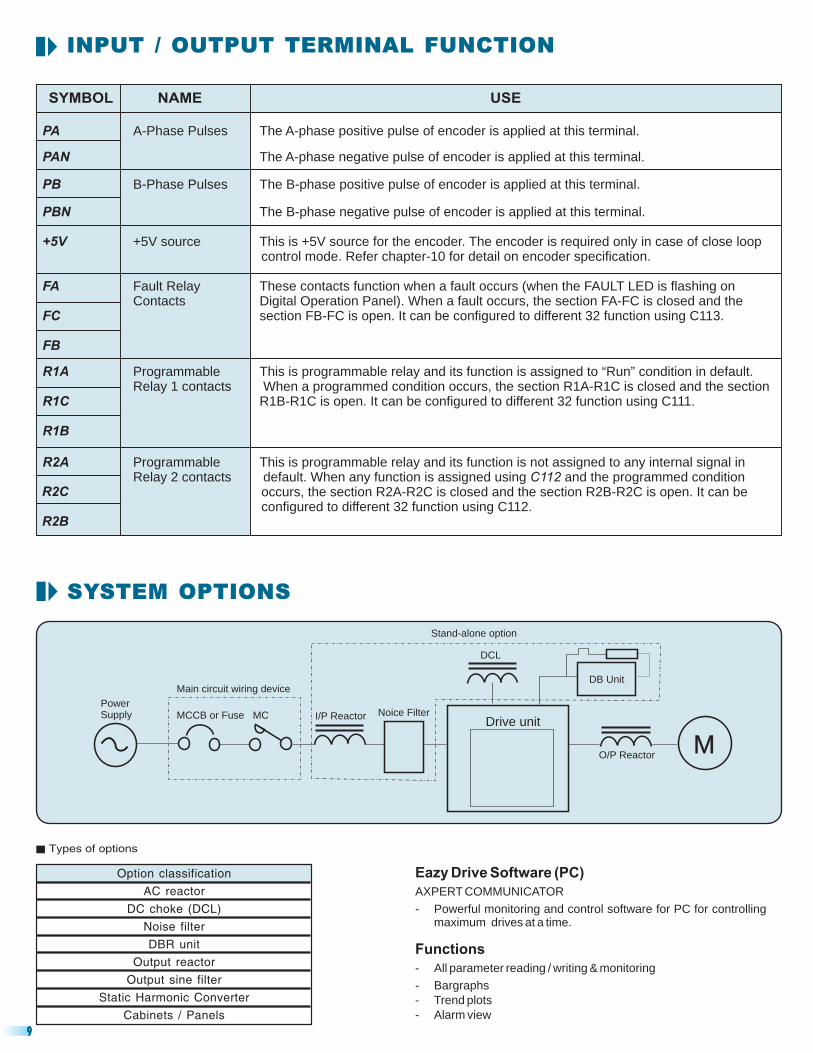
INPUT / OUTPUT TERMINAL FUNCTION
SYMBOL NAME USE
COM
RX DATA-
+24V
RUN
STOP
P15
0V
VIN
IIN
VO1
IO1
TX
+24V source This source is used for the Programmable Sequence Inputs. The logic for theProgrammable Sequence Inputs can be changed to sink or source with the help ofon the control board.
RUN command
STOP command
Inputs 1 ~ 6
Outputs 1 ~ 4
+15V source This is used when a frequency setter is connected to the FSV inputcircuit. The frequency setter to be used should be a variable resistor of 2k and 2W.
Common This is a common terminal for analog input signals.
Setting Voltageinput 10-0V or FSV 5-0V is selected as frequency reference input in or or torque
reference input in . Also, this input can be configured as PID Reference input( ) or PID Feedback input ( ) or Math Reference Input2 or Variable bias
for math operation.
SettingCurrent input FSI 20-0mA or FSI 20-4mA is selected as frequency reference input in or or
torque reference input in . Also, this input can be configured as PID Referenceinput ( ) or PID Feedback input ( )
Voltage input This is mainly used for setting the frequency (speed) input. A maximum frequencysetting is available at 10V input. This setting is valid when VIN 0-10V is selected asfrequency reference input in . Also, this input can be configured as PID Referenceinput ( ) or PID Feedback input ( )
Current Input This is mainly used for setting the frequency (speed) input. A maximum frequencysetting is available at 20mA input. This setting is valid when IIN 4-20mA is selected asfrequency reference input in . Also, this input can be configured as PID Referenceinput ( ) or PID Feedback input ( )
Vout-1 These are programmable analog voltage outputs 0-10V. In default condition, output
Iout-1 These are programmable analog current outputs 4-20mA. In default condition, motorpower signal is assigned to IO1 and output voltage signal is assigned to IO2. Different
DATA+ These two signals are for the two-wire RS-485 serial link. The protocol used is
JP1
This is programmable sequence input and can be configured to different 35 functionsusing C114.
These are programmable sequence inputs and can be configured todifferent 35 functions using C101 ~ C106.
These are programmable sequence outputs different 32 functions usingC107 ~ C110.
This is programmable sequence input and can be configured to different 35 functionsusing C115.
ProgrammableSequence
ProgrammableSequence
Frequency This is mainly used for setting the frequency (speed) input. A maximum frequencysetting is available at 10V input. This setting is valid when FSV 0-10V, FSV 0-5V, FSV
Frequency This is mainly used for setting the frequency (speed) input. A maximum frequencysetting is available at 20mA input. This setting is valid when FSI 0-20mA, FSI 4-20mA,
or Math Reference Input2 orVariable bias for math operation.
or Math Reference Input2 orVariable bias for math operation.
or Math Reference Input2 orVariable bias for math operation.
frequency signal is assigned to VO1 and output current signal is assigned to VO2.Vout-2 Different seven internal signals can be assigned to these outputs using & .
Iout-2 seven internal signals can be assigned to these outputs using & .
Modbus-RTU.
PSI1-6
PSO1-4
FSV
FSI
VO2
IO2
A106 D204A108
C603 C604 (A702)(A706)
A106 D204A108
C603 C604
A106C603 C604
A106C603 C604
(A702)(A706)
(A702)(A706)
(A702)(A706)
C201 C202
C203 C204
8
INPUT / OUTPUT TERMINAL FUNCTION
Eazy Drive Software (PC)
Functions
AXPERT COMMUNICATOR
- Powerful monitoring and control software for PC for controllingmaximum drives at a time.
- All parameter reading / writing & monitoring
- Bargraphs
- Trend plots
- Alarm view
M
Stand-alone option
PowerSupply
Main circuit wiring device
MCCB or Fuse MC I/P Reactor Noice Filter
DCL
DB Unit
Drive unit
O/P Reactor
SYSTEM OPTIONS
Option classification
AC reactor
DC choke (DCL)
Noise filter
DBR unit
Output reactor
Output sine filter
Static Harmonic Converter
Cabinets / Panels
Types of options
SYMBOL NAME USE
R2C
R2B
PA
PAN
PB
PBN
+5V
FA
FB
R1A
R1B
R2A
A-Phase Pulses The A-phase positive pulse of encoder is applied at this terminal.
The A-phase negative pulse of encoder is applied at this terminal.
B-Phase Pulses The B-phase positive pulse of encoder is applied at this terminal.
The B-phase negative pulse of encoder is applied at this terminal.
+5V source This is +5V source for the encoder. The encoder is required only in case of close loopcontrol mode. Refer chapter-10 for detail on encoder specification.
Fault Relay These contacts function when a fault occurs (when the FAULT LED is flashing onDigital Operation Panel). When a fault occurs, the section FA-FC is closed and the
ProgrammableRelay 1 contacts When a programmed condition occurs, the section R1A-R1C is closed and the section
ProgrammableRelay 2 contacts default. When any function is assigned using and the programmed condition
occurs, the section R2A-R2C is closed and the section R2B-R2C is open.
Contactssection FB-FC is open. It can be configured to different 32 function using C113.
This is programmable relay and its function is assigned to “Run” condition in default.
R1B-R1C is open. It can be configured to different 32 function using C111.
This is programmable relay and its function is not assigned to any internal signal in
It can beconfigured to different 32 function using C112.
FC
R1C
C112
9
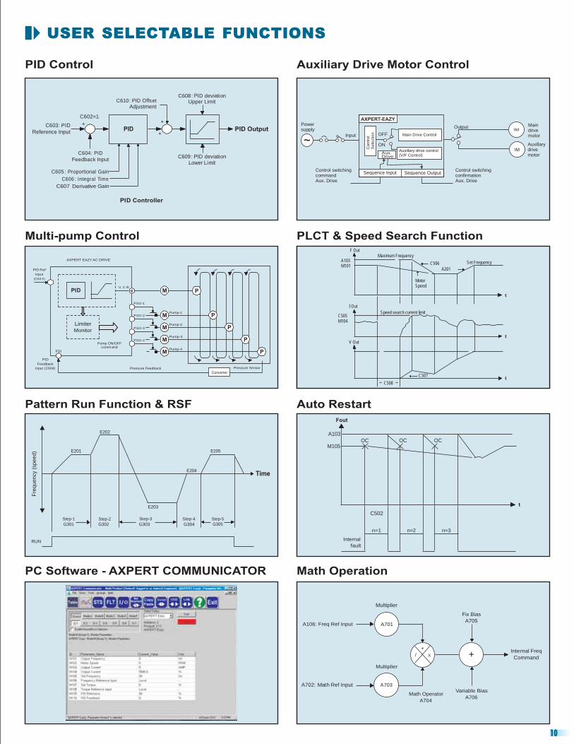
USER SELECTABLE FUNCTIONS
Multi-pump Control
PID Control Auxiliary Drive Motor Control
Auxillarydrivemotor
Powersupply
Input OFF
ON
Control switchingcommandAux. Drive
Control switchingconfirmationAux. Drive
Output Maindrivemotor
IM
IM
Main Drive Control
Auxillary drive control(V/F Control)
Sequence Input Sequence Output
AXPERT-EAZY
Contr
ol
Sele
ction
Aux.Drive
Pattern Run Function & RSF
PLCT & Speed Search Function
Auto Restart
PC Software - AXPERT COMMUNICATOR Math Operation
10
++
+
PID PID Output
C609 : PID deviationLower Limit
C603: PID
Reference Input
C602=1
C604: PID
Feedback Input
C605 : Proportional Gain
C606 : Integral Time
C607 Derivative Gain
PID Controller
C610: PID OffsetAdjustment
C608: PID deviationUpper Limit
PID M
M
M
M
M
P
P
P
P
P
ConverterPressure Feedback
Pump ON/OFF
comm and
PSO -4
PSO -3
PSO -2
PSO -1
U, V, W
LimiterMonitor
FSI
PID
Feedback
Input (C604)
AXPERT EAZY AC DRIVE
PID Ref
Input
(C60 3)
Pump-1
Pump-2
Pump-3
Pump-4
Pressure Sensor
Fre
quency (
speed) E201
E202
E203
E204
E205
Time
RUN
Step-1
G301Step-2
G302
Step-3
G303
Step-4
G304
Step-5
G305
F Out
A103M101
Maximum Frequency
C506
A201
Set Frequency
MotorSpeed
t
t
tC507
C508
C505M104
I Out
V Out
Speed search current limit
Fout
A103
M105OC OC OC
C502
n=1 n=2 n=3
Internal
fault
t
A702: Math Ref Input
A106: Freq Ref Input
Multiplier
Multiplier
Math Operator
A704
Variable Bias
A706
Internal Freq
Command
A703
Fix Bias
A705
X/
+
+
A701
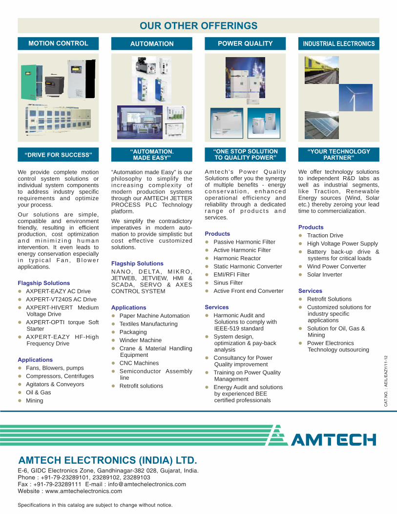
OUR OTHER OFFERINGS
We provide complete motioncontrol system solutions orindividual system componentsto address industry specificrequirements and optimizeyour process.
Our solutions are simple,compatible and environmentfriendly, resulting in efficientproduction, cost optimizationa n d m i n i m i z i n g h u m a nintervention. It even leads toenergy conservation especiallyi n t y p i c a l F a n , B l o w e rapplications.
AXPERT-EAZY AC Drive
AXPERT-VT240S AC Drive
AXPERT-HIVERT MediumVoltage Drive
AXPERT-OPTI torque SoftStarter
AXPERT-EAZY HF-HighFrequency Drive
Fans, Blowers, pumps
Compressors, Centrifuges
Agitators & Conveyors
Oil & Gas
Mining
Flagship Solutions
Applications
�
�
�
�
�
�
�
�
�
�
CA
T.N
O.
:A
EIL
/EA
ZY
/11-
12
“Automation made Easy” is ourphilosophy to simplify theincreasing complexi ty ofmodern production systemsthrough our AMTECH JETTERPROCESS PLC Technologyplatform.
We simplify the contradictoryimperatives in modern auto-mation to provide simplistic butcost effective customizedsolutions.
NANO, DELTA, MIKRO,JETWEB, JETVIEW, HMI &SCADA, SERVO & AXESCONTROL SYSTEM
Paper Machine Automation
Textiles Manufacturing
Packaging
Winder Machine
Crane & Material HandlingEquipment
CNC Machines
Semiconductor Assemblyline
Retrofit solutions
Flagship Solutions
Applications
�
�
�
�
�
�
�
�
Amtech 's Power Qual i tySolutions offer you the synergyof multiple benefits - energyconse rva t i on , enhancedoperational efficiency andreliability through a dedicatedr a n g e o f p r o d u c t s a n dservices.
Passive Harmonic Filter
Active Harmonic Filter
Harmonic Reactor
Static Harmonic Converter
EMI/RFI Filter
Sinus Filter
Active Front end Converter
Harmonic Audit andSolutions to comply withIEEE-519 standard
System design,optimization & pay-backanalysis
Consultancy for PowerQuality improvement
Energy Audit and solutionsby experienced BEEcertified professionals
Products
Services
�
�
�
�
�
�
�
�
�
�
�
�
Training on Power QualityManagement
We offer technology solutionsto independent R&D labs aswell as industrial segments,l ike Traction, RenewableEnergy sources (Wind, Solaretc.) thereby zeroing your leadtime to commercialization.
Traction Drive
High Voltage Power Supply
Battery back-up drive &systems for critical loads
Wind Power Converter
Solar Inverter
Retrofit Solutions
Customized solutions forindustry specificapplications
Solution for Oil, Gas &Mining
Power ElectronicsTechnology outsourcing
Products
Services
�
�
�
�
�
�
�
�
�
Specifications in this catalog are subject to change without notice.
MOTION CONTROL AUTOMATION POWER QUALITY INDUSTRIAL ELECTRONICS
“DRIVE FOR SUCCESS”“AUTOMATION.MADE EASY”
“ONE STOP SOLUTIONTO QUALITY POWER”
“YOUR TECHNOLOGYPARTNER”
i-SineAXPERT-Active Harmonic Filter
i-SineAXPERT-Active Harmonic Filter
E-6, GIDC Electronics Zone, Gandhinagar-382 028, Gujarat, India.Phone : +91-79-23289101, 23289102, 23289103Fax : +91-79-23289111 E-mail : [email protected] : www.amtechelectronics.com
AMTECH ELECTRONICS (INDIA) LTD.
N o r m0 . 0 % L 4 1 5 V r y0 . 0 l r 0 0 VoV R a m p . L c l , S t o p