ac traction inverters - zener.com.cnzener.com.cn/sitecn/uppic/c_10_15.pdfÊenvironment is very harsh...
TRANSCRIPT

HOME
AC Traction Inverters
Presentation forBombardier
byQingdao Zener Electric Co., Ltd

HOME
Introduction to the parent company:GNDC CO., LTD
Company profileSince 1977 GNDC CO., Ltd has focused on
manufacturing quality products related to power electronic field. Started from our first product –thyristor triggering board, we have produced tens of thousands of DC motor drives, temperature control units, UPS’s, power supplies, various assembled PCB’s…. in the past ages .

HOME
Introduction to the parent company:GNDC CO., LTD
Our current business plan is to focus on designing and manufacturing the following :
1. Frequency inverters for AC motor drives2. Active front ends for 4-Q converters3. Active filters for better electricity quality4. Traction inverters for light rail trains5. High power semiconductor stacks for
industrial and military use

HOME
Introduction to the parent company:GNDC CO., LTD
Our visionCreating products that will help save energy and promote better living and help the environment.
Our missions1. We strive for innovative technologies and products2. We are committed to grow with our customers3. We need to create an environment where ideas
are encouraged, recognized and rewarded. 4. We want to help our employees grow personally
and professionally.

HOME
Introduction to the parent company:GNDC CO., LTD
Quality AssuranceExcellence in quality and reliability is our primary goal.
We believe it is more economical and efficient to prevent defects from occurring in advance than correcting them afterwards, we start with product design and beingstressed throughout the entire manufacturing cycle. Quality assurance is responsible for all phases of quality from design evaluation through material procurement, in process inspection during the manufacturing cycle, product test, shipping and field reliability tracking.We are an ISO9001 certified manufacturer.

HOME
Introduction to the parent company: GNDC CO., LTD
AffiliatesPan Hao Co., Ltd
(www.panhao.com)Semcor (Qingdao) Electronic Co., Ltd
(www.semcor.com.cn)Qingdao Zener Electric Co., Ltd
(www.zener.com.cn) Qingdao Zencon Electric Co., Ltd

HOME
Light Rail Traction
The Zener Traction Drive System (ZTDS)

HOME
Light Rail
600 or 750VDC supply
City use
Frequent stop / start
Typically 30 tonne / unit

HOME
Introduction
The use of inverters is well known, but there are special requirements for rail
Electrical
Mechanical
System
All these must be met to make a reliable system

HOME
Introduction
Electrical Requirements…Powered from DC overhead line or 3rd rail
Wide voltage range, typically –30% to +20%
Large, high energy transients on the DC supply
Interface to the train system
Torque control by steps
Large overload capacity

HOME
Introduction
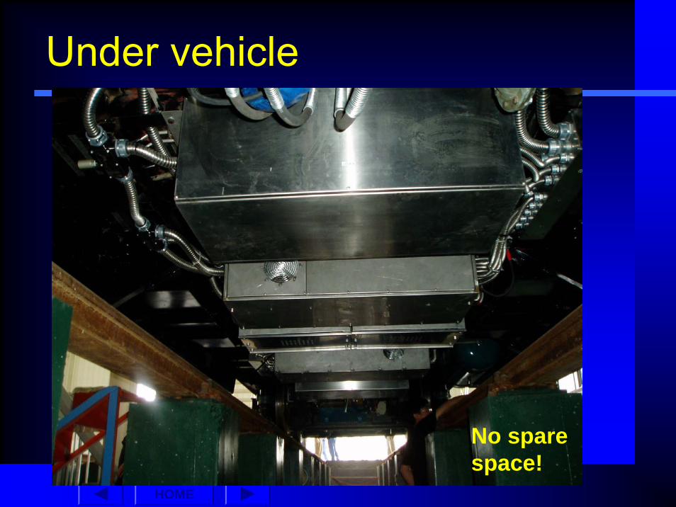
Mechanical Requirements…Space is always a problem on a train
Compact design essential
Equipment must withstand shock and vibration

HOME
Introduction
Other System Requirements…High reliability is essential
Running costs must be minimized by efficient energy use
Capital cost must be as low as possible

HOME
The System
Slow charge circuit
-
+
RC
Overhead line
LLightning Arrestor
Pantograph
Regenbraking
Resistive braking
Circuit breaker
INDUCTIONMOTOR
Track return circuit
Rectifiersub-station
750VDC Nominal
(20kA short circuit)
IGBTINVERTER
Distributed L, RDistributed L, R

HOME
Technology
Power semiconductor (IGBTs, diodes) sub-systems
Allows 150% and 200% overload
Control system specially designed by Zener for traction drive applications

HOME
International Technical Standards Compliance
Most Commonly applied standard is
International Electrotechnical Commission (IEC) standard
1287-1 Power converters installed on board rolling stock
The equipment presented here meets this and other standards.

HOME
Power sourceSupply voltage range for contentious operation -30% to +20%. For a 750VDC system this is 525 -900V
Low voltage limit is necessary for emergency operation of the railway when some of the track side power supplies (rectifier sub-stations) are not working
High voltage limit is to allow the use of energy saving regenerative braking with the least use of wasteful resistive or mechanical braking

HOME
Electrical TransientsHigh inductance in overhead wire (~1.5mH/km)
High fault currents possible
Large stored energy (0.5 x L x I2)
Proper design for transient voltages is essential for a reliable system

HOME
Electrical Transients…

HOME
Interface to the train controls systemZTDS provides two kind of interface
24VDC control interface using relay contacts and electronic relay "coils" that allows control of the driving or braking torque step as well as signalling of fault conditions
Industry standard MODBUS serial communications protocol
Allows access to a wider range of control features and reporting of operating conditions including fault status, currents, voltages and power measurements in real time

HOME
ZTDS Control SystemHigh performance Texas Digital Signal Processor (DSP)
Driving / braking in multiple steps
Slow charge control for inverter DC link
2 line LCD display & keypad for testing / maintenance and parameter setting

HOME
ZTDS Control SystemRS-485 serial interface (MODBUS protocol)
Relay contacts for status signals
Highly reliable hardware
Can drive two AC traction motors in parallel -Reduce the overall cost

HOME
Outline
The traction application – mechanical overviewTraction motor environment - bogie constructionInduction motor performanceTorque productionDecoupling flux and torqueSensorless operationControl topology, description

HOME
Traction requirements
The traction system needs to provide sufficient force parallel to the rail (tractive effort) for:
AccelerationClimbing slopesFrictionWindage
A regenerative capability is normally required for energy efficiency

HOME
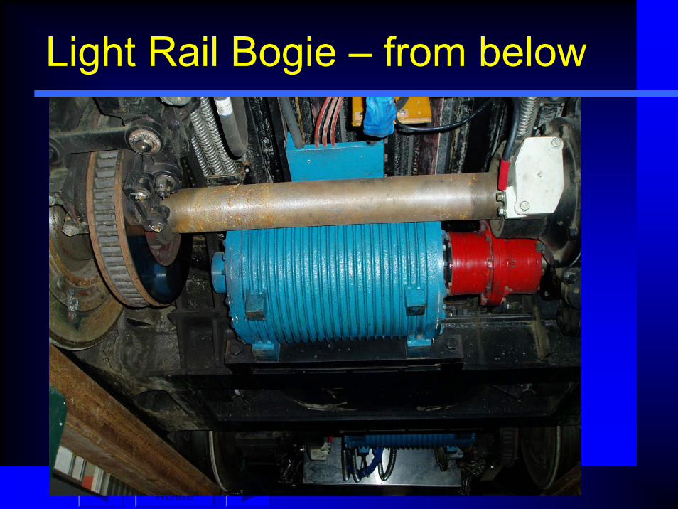
Light Rail Bogie
Brake disc
AC traction motor
Gearbox
AC traction motor
Figure 2 Light rail bogie
HOME
Light Rail Bogie – from below
HOME
Under vehicle
No spare space!

HOME
Wheel and Rail
Tractive effortF = Torque x radius
Maximum tractive effortF = μ x axle weight
Axle weight
Reaction force on rail
Torque applied by traction drive
μ = coefficient of adhesion
Figure 1Basic Forces

HOME
Advantages of AC TractionMore rugged traction motors
Environment is very harsh - vibration, shock, waterImpact on the motor case, obstruct ventilation openings etc.
Low maintenanceNo brushgearUsually no ventilation openings
Multiple motors may be driven by one inverterEconomy
Improved wheel slip performance conditions
HOME
Challenges of AC Traction
More complex controlDigital Signal Processors (DSP) allow complex control structures to be implemented economically and reliably
Speed sensor usually required on the motorLowers reliabilityAdds costTakes space
Speed-sensorless control can avoid this!
HOME
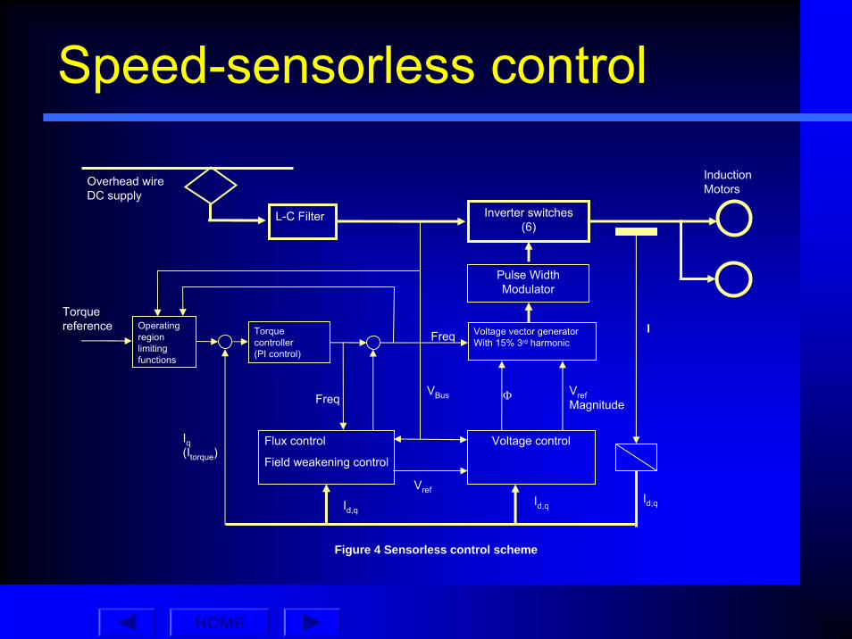
Speed-sensorless control
Induction Motors
Inverter switches(6)
Pulse Width Modulator
Voltage vector generatorWith 15% 3rd harmonic
Voltage controlFlux control
Field weakening control
Torque controller(PI control)
I
Overhead wireDC supply
Torque reference
L-C Filter
Id,qId,q
Iq(Itorque)
VBus
Id,q
Φ VrefMagnitude
Freq
Vref
Freq
Operating region limiting functions
Figure 4 Sensorless control scheme

HOME
Torque Production – Induction Machine3-phase
AC supply 1. Rotating magnetic field
2. Current induced in rotor conductors
4 pole machine shown
N
N
S
S
N
N
S
S

HOME
Induction Motor Characteristics
Torque
Motor shaft speed
+
(driving)
-(regeneration)
Synchronous speed
Shaft speed = stator frequency
No rotor current
No torque produced
Breakdown torque
Breakdown torque

HOME
Induction Motor Characteristics
Constant torque Constant power Reduced power
Figure 3 Induction machine operating regions
Speed
Breakdowntorque
Rated torque
Torque

HOME
DecouplingDecoupling
Separates torque and magnetic flux production by “untangling” the stator current information
Simplifies the control structure(so that it can be like a DC machine)
Key element of field oriented control.

HOME
Decoupled Control
By definition:
Decoupled control = separate flux and torque control
By implication:Separate (constant) flux control→ decoupled control → torque control

HOME
Typical SpecificationInput voltage 450-900VDC
Maximum operating input voltage 1200V
Exceptional peak input voltage 1500V
Output voltage 480V RMS
Output current Depending on actual requirement
cosϕ 0.85 to 0.9
Output frequency 0.5Hz to 150Hz
Overload Depending on actual requirement
Switching frequency 1 kHz
Ambient temperature 25 to +40°C
Capacitors lifetime -100,000 hours at 1000V at 70°C without over voltages
Cooling fluid Filtered air
Altitude <1200m above sea level
Humidity Non-condensed 85%
Mechanical protection IP00
HOME
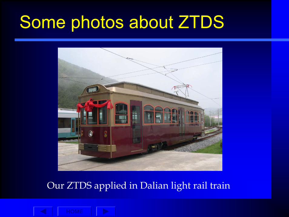
Some photos about ZTDS
Our ZTDS applied in Dalian light rail train

HOME
The DSP control for ZTDS

HOME
The simulation load for ZTDS development

HOME
What is our latest development?
Now we can supply the traction inverter for the input voltage 1500VDC which is widely used for light rail train and under-ground subway system.

HOME
What else we can supply
Emergency ventilation inverters, battery chargers….Please see our sales reference below:
Qty Description Ratings Fleet Operator Zener Partnumber
386 Emergency ventilation inverter and output transformer
Input: 110Vdc Output: 55Vac/45Hz/3 ph feeding
step-up transformer.Inverter based on MSC-3R30
New Delhi DMRC ZM00304
208 Emergency ventilation inverter and output transformer
Input: 110Vdc Output: 55Vac/45Hz/3 ph feeding
step-up transformer.Inverter based on MSC-3R30
Hong Kong MTRC ZM00304
110 Battery charger and LV power supply
Input: 600Vdc (from overhead line) Output 24Vdc / 90A
Yarra Trams, Z1/Z2 Class passenger trams operating in Melbourne, Australia
Y0037
22 Battery charger and LV power supply
Input: 415V/50Hz/3-ph/PWM (unfiltered from inverter)
Output 24Vdc / 120A
V/Line passengers, Sprinter DMU intercity railcars operating in regional Victoria, Australia
ZM00100

HOME
Sales reference further
48 Air conditioning inverters 10A and 24A
Input: 415Vac 50Hz/3-phOutput: 415V/50Hz 10A
(ZM00044) and 24A (ZM00045)
Queensland Rail (QR)Rockhampton to Brisbane Tilt
Train passenger vehicles
ZM00044 & ZM00045
280 Emergency ventilation inverter and output transformer
Input: 120VdcOutput: 61Vac/35Hz feeding
step-up transformer
Millennium passenger trains operating in metropolitan Sydney, Australia
ZM00308
900 Emergency ventilation inverter
Input: 120VdcOutput: 55V/21Hz supplying
fan motor
Tangara and K Class passenger trains operating in metropolitan Sydney, Australia
ZM00300

HOME
Battery Chargers for Rail and Tram Vehicles
.Custom designed and manufactured to the highest quality. .Comply with international railway / rolling stock standards. .Type testing to IEC 61287-1:1995-07 Power converters installed on board rolling stock Part 1:
Characteristics and test methods. .Proven reliability – references available on request. Lifetime support & back up. The Sprinter Battery Charger was designed to provide a significant increase in capacity, replacing an earlier Zener model. The new design achieved an improvement in output from 70A to 120A with no increase in weight or footprint. In addition, a number of new enhancements were incorporated, including limited operation under phase loss conditions, large illuminated current and voltage displays and improved dynamic performance.

HOME
Battery Chargers for Rail and Tram Vehicles
The Z1 / Z2 Tram Battery Charger was designed to operate from the tram 600Vdc overhead line. A special requirement of the tram operator was that the charger had to withstand inadvertent connection to the rail overhead line – 1500V – at rail and tram crossing points, without failure. The winning design included a 2000V continuous withstand capability with automatic restart, eliminating the need for driver intervention. Over 100 units were supplied and in seven years of operation, no unit has requiredservice.

HOME
Thank you for your attention
Qingdao Zener Electric Co., LtdTel: 0532-88701773
Fax:0532-88701478
http://www.zener.com.cn