ac circuit - houston community college
TRANSCRIPT
AC Circuit
• An AC circuit consists of a combination of circuit elements and an AC generator or source.
• The output of an AC generator is sinusoidal and varies with time according to the following equation– Δv = ΔVmax sin 2ƒt
• Δv is the instantaneous voltage
• ΔVmax is the maximum voltage of the generator
• ƒ is the frequency at which the voltage changes, in Hz
Section 21.1

Resistor in an AC Circuit
• Consider a circuit consisting of an AC source and a resistor.
Resistor, Cont.
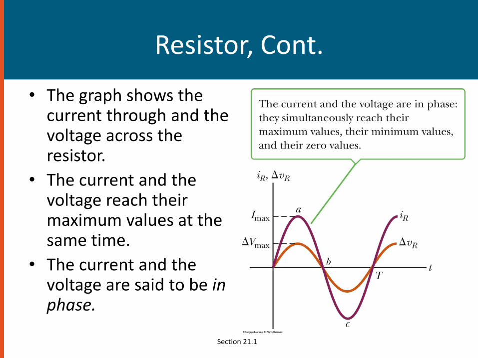
• The graph shows the current through and the voltage across the resistor.
• The current and the voltage reach their maximum values at the same time.
• The current and the voltage are said to be in phase.
Section 21.1

rms Current and Voltage
• The rms current is the direct current that would dissipate the same amount of energy in a resistor as is actually dissipated by the AC current.
• Alternating voltages can also be discussed in terms of rms values.
Section 21.1
rms Graph
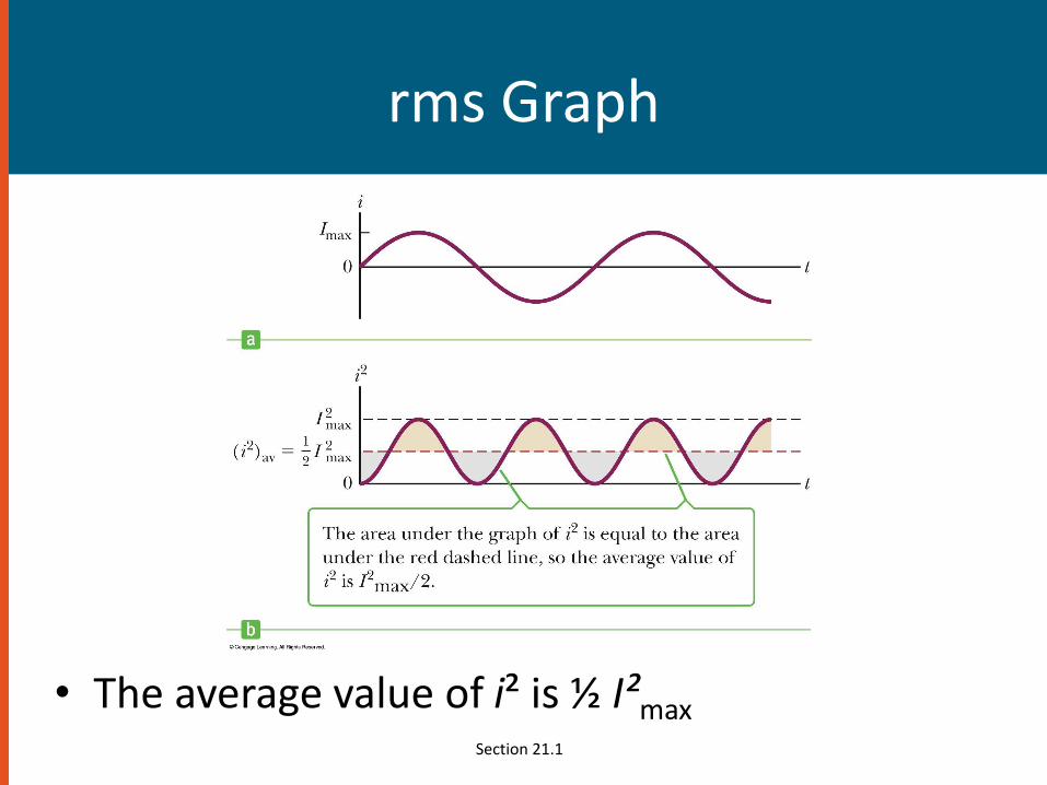
• The average value of i² is ½ I²maxSection 21.1

Ohm’s Law in an AC Circuit
• rms values will be used when discussing AC currents and voltages.– AC ammeters and voltmeters are designed to read
rms values.
– Many of the equations will be in the same form as in DC circuits.
• Ohm’s Law for a resistor, R, in an AC circuit– ΔVR,rms = Irms R
• Also applies to the maximum values of v and i
Section 21.1
Capacitors in an AC Circuit
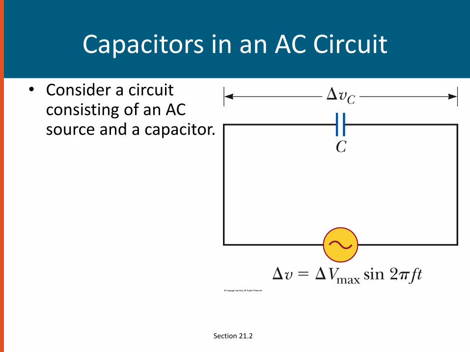
• Consider a circuit consisting of an AC source and a capacitor.
Section 21.2
More About Capacitors in an AC Circuit
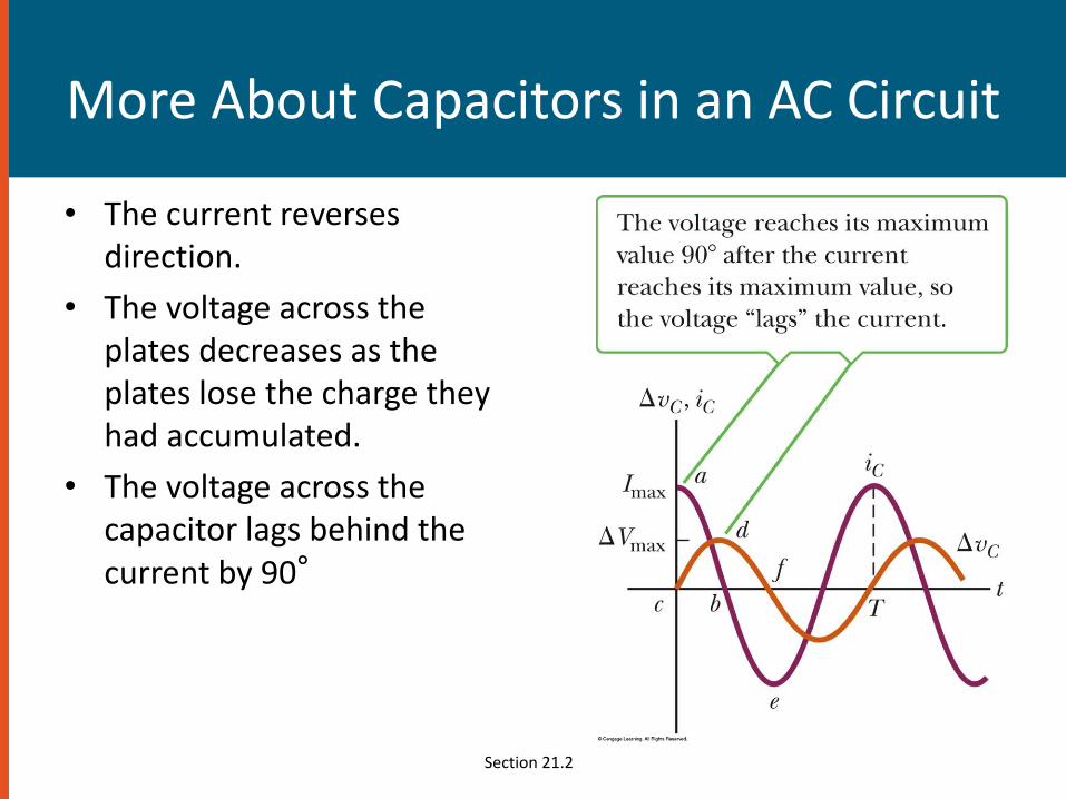
• The current reverses direction.
• The voltage across the plates decreases as the plates lose the charge they had accumulated.
• The voltage across the capacitor lags behind the current by 90°
Section 21.2

Capacitive Reactance and Ohm’s Law
• The impeding effect of a capacitor on the current in an AC circuit is called the capacitive reactance and is given by
– When ƒ is in Hz and C is in F, XC will be in ohms
• Ohm’s Law for a capacitor in an AC circuit– ΔVC,rms = Irms XC
Section 21.2
Inductors in an AC Circuit
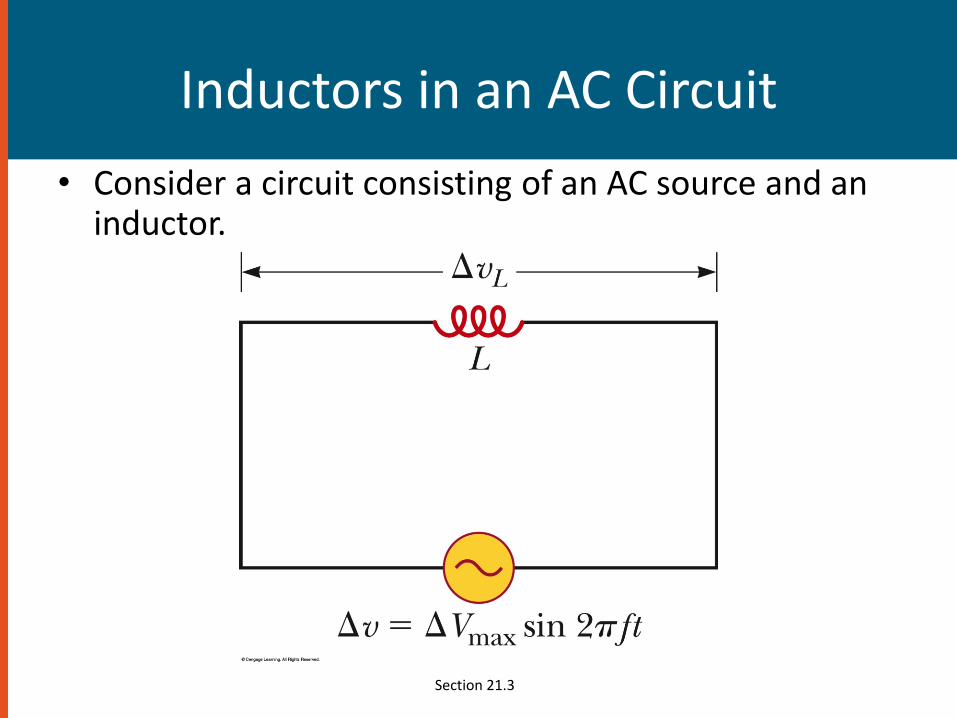
• Consider a circuit consisting of an AC source and an inductor.
Section 21.3
Inductors in an AC Circuit
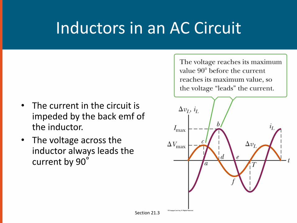
• The current in the circuit is impeded by the back emf of the inductor.
• The voltage across the inductor always leads the current by 90°
Section 21.3
Inductive Reactance and Ohm’s Law
• The effective resistance of a coil in an AC circuit is called its inductive reactance and is given by
– XL = 2ƒL
• When ƒ is in Hz and L is in H, XL will be in ohms
• Ohm’s Law for the inductor
– ΔVL,rms = Irms XL
Section 21.3
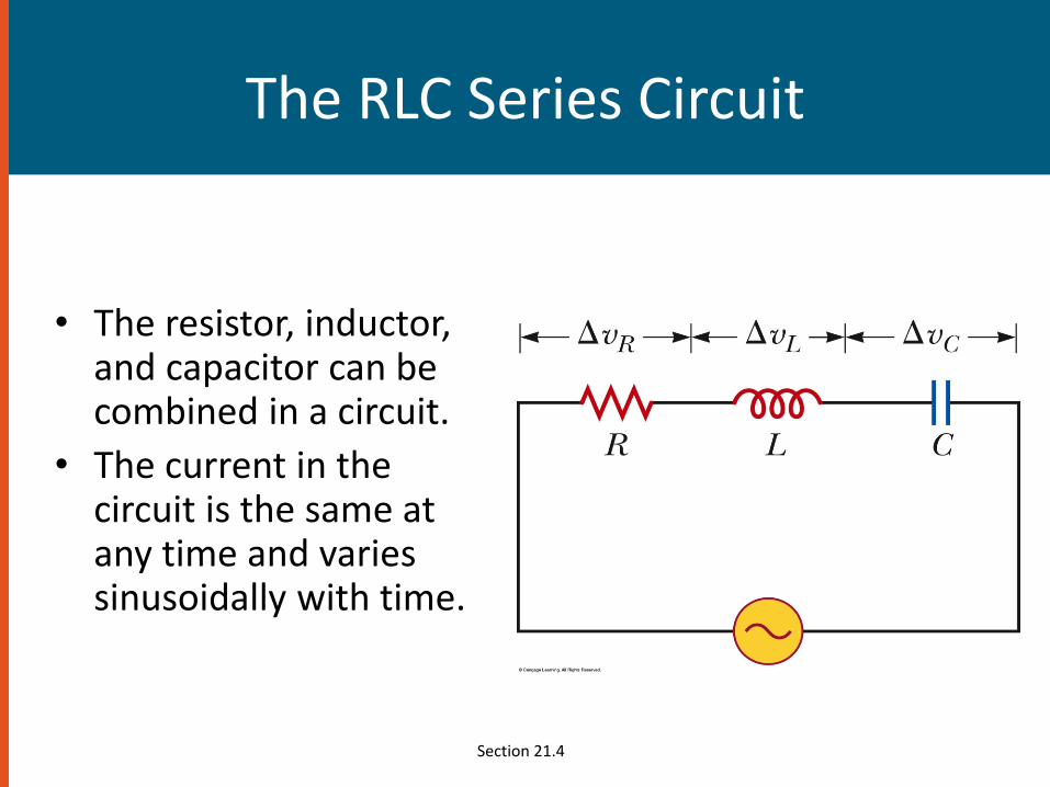
The RLC Series Circuit
• The resistor, inductor, and capacitor can be combined in a circuit.
• The current in the circuit is the same at any time and varies sinusoidally with time.
Section 21.4

Current and Voltage Relationships in an RLC Circuit, Graphical Summary
• The instantaneous voltage across the resistor is in phase with the current.
• The instantaneous voltage across the inductor leads the current by 90°
• The instantaneous voltage across the capacitor lags the current by 90°
Section 21.4

Phasor Diagrams
• To account for the different phases of the voltage drops, vector techniques are used.
• Represent the voltage across each element as a rotating vector, called a phasor.
• The diagram is called a phasor diagram.
Section 21.4
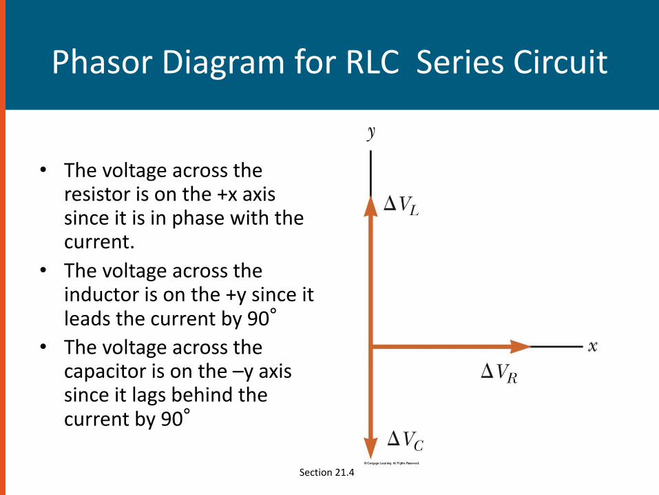
Phasor Diagram for RLC Series Circuit
• The voltage across the resistor is on the +x axis since it is in phase with the current.
• The voltage across the inductor is on the +y since it leads the current by 90°
• The voltage across the capacitor is on the –y axis since it lags behind the current by 90°
Section 21.4
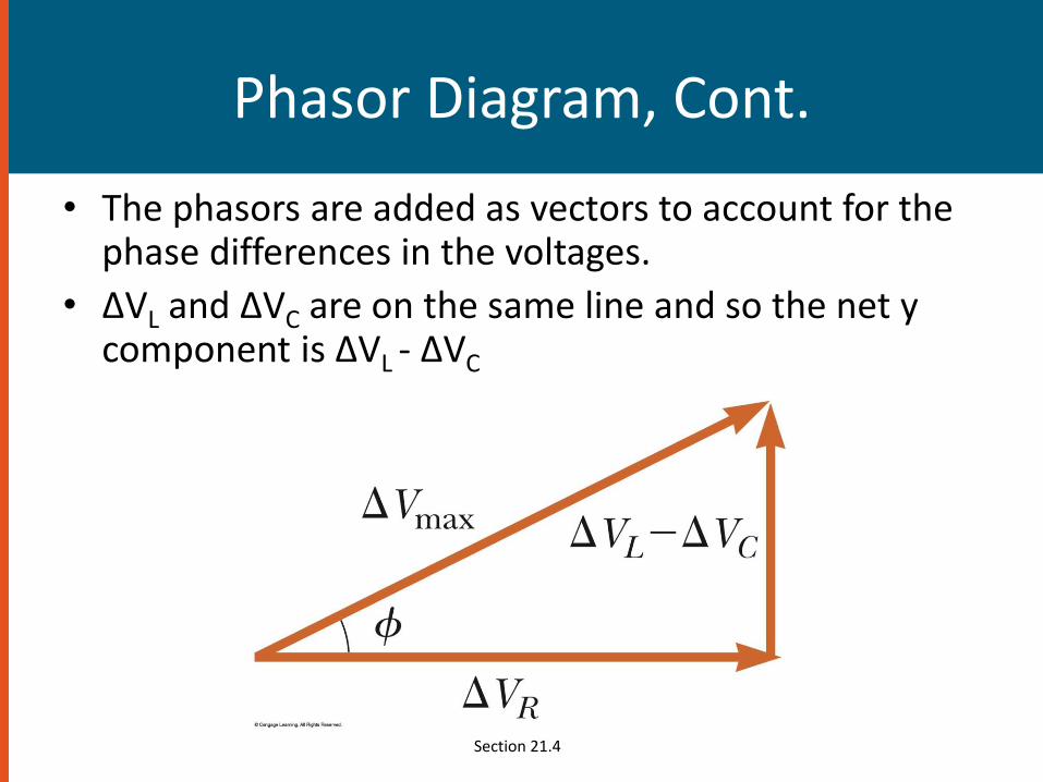
Phasor Diagram, Cont.
• The phasors are added as vectors to account for the phase differences in the voltages.
• ΔVL and ΔVC are on the same line and so the net y component is ΔVL - ΔVC
Section 21.4
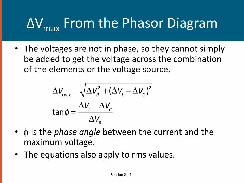
ΔVmax From the Phasor Diagram
• The voltages are not in phase, so they cannot simply be added to get the voltage across the combination of the elements or the voltage source.
• is the phase angle between the current and the maximum voltage.
• The equations also apply to rms values.
Section 21.4

Impedance of a Circuit
• The impedance, Z, can also be represented in a phasor diagram.
Section 21.4

Impedance and Ohm’s Law
• Ohm’s Law can be applied to the impedance.
– ΔVmax = Imax Z
– This can be regarded as a generalized form of Ohm’s Law applied to a series AC circuit.
Section 21.4

Summary of Circuit Elements, Impedance and Phase Angles
Problem
A 90 Ω resistor, a 0.25 μF capacitor and a 2.5 Hinductor are connected in series across 60 Hz ACsource V = 10 sin wt. Find (a) the impedance ofthe circuit (b) maximum current through thecircuit (c) phase difference between the currentand voltage (d) frequency of AC mains at whichresonance occurs.

Transformers
• An AC transformer consists of two coils of wire wound around a core of soft iron.
• The side connected to the input AC voltage source is called the primary and has N1 turns.
Section 21.7
Transformers
• The other side, called the secondary, is connected to a resistor and has N2 turns.
• The core is used to increase the magnetic flux and to provide a medium for the flux to pass from one coil to the other.
• The rate of change of the flux is the same for both coils.
Section 21.7
Transformers
• The voltages are related by
• When N2 > N1, the transformer is referred to as a step up transformer.
• When N2 < N1, the transformer is referred to as a step down transformer.
• Since the power has to be conserved

Problem
A transformer is to be used to provide power foran electronics that needs 6 V rms instead of the120 V Ac mains. If the number of turns in theprimary of the transformer is 400, what shouldbe the number of turns in the secondary?
Electromagnetic Waves
• A changing magnetic field produces an electric field.
• A changing electric field produces a magnetic field.
• These fields are in phase.
– At any point, both fields reach their maximum value at the same time.
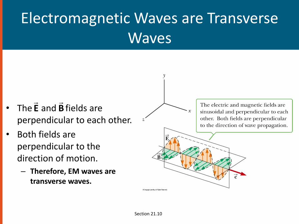
Electromagnetic Waves are Transverse Waves
• The and fields are perpendicular to each other.
• Both fields are perpendicular to the direction of motion.– Therefore, EM waves are
transverse waves.
Section 21.10
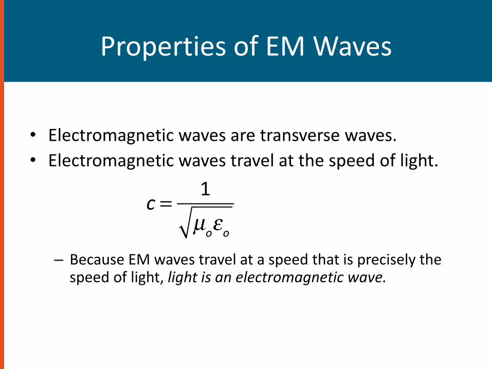
Properties of EM Waves
• Electromagnetic waves are transverse waves.
• Electromagnetic waves travel at the speed of light.
– Because EM waves travel at a speed that is precisely the speed of light, light is an electromagnetic wave.
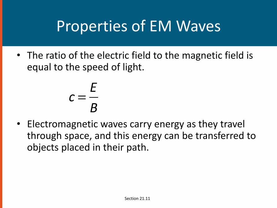
Properties of EM Waves
• The ratio of the electric field to the magnetic field is equal to the speed of light.
• Electromagnetic waves carry energy as they travel through space, and this energy can be transferred to objects placed in their path.
Section 21.11
Properties of EM Waves
• EM waves travel at the speed of light.
• EM waves are transverse waves because the electric and magnetic fields are perpendicular to the direction of propagation of the wave and to each other.
• The ratio of the electric field to the magnetic field in an EM wave equals the speed of light.
• EM waves carry both energy and momentum, which can be delivered to a surface.
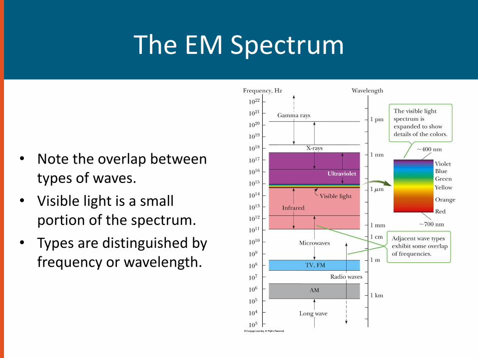
The EM Spectrum
• Note the overlap between types of waves.
• Visible light is a small portion of the spectrum.
• Types are distinguished by frequency or wavelength.
Notes on The EM Spectrum
• Radio Waves
– Used in radio and television communication systems
• Microwaves
– Wavelengths from about 1 mm to 30 cm
– Well suited for radar systems
– Microwave ovens are an application
Section 21.12

Notes on the EM Spectrum
• Infrared waves– Incorrectly called “heat waves”
– Produced by hot objects and molecules
– Wavelengths range from about 1 mm to 700 nm
– Readily absorbed by most materials
• Visible light– Part of the spectrum detected by the human eye
– Wavelengths range from 400 nm to 700 nm
– Most sensitive at about 560 nm (yellow-green)
Notes on the EM Spectrum
• Ultraviolet light– Covers about 400 nm to 0.6 nm
– The Sun is an important source of uv light.
– Most uv light from the sun is absorbed in the stratosphere by ozone.
• X-rays– Wavelengths range from about 10 nm to 10-4 nm
– Most common source is acceleration of high-energy electrons striking a metal target
– Used as a diagnostic tool in medicine
Section 21.12

Notes on the EM Spectrum
• Gamma rays
– Wavelengths from about 10-10 m to 10-14 m
– Emitted by radioactive nuclei
– Highly penetrating and cause serious damage when absorbed by living tissue
• Looking at objects in different portions of the spectrum can produce different information.
Section 21.12
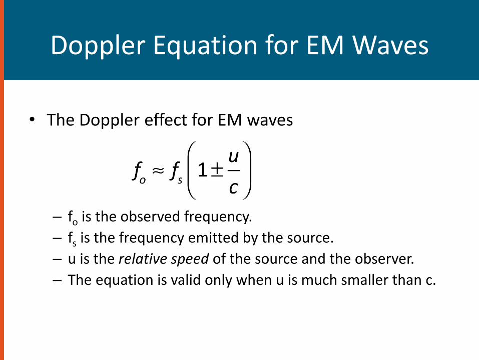
Doppler Equation for EM Waves
• The Doppler effect for EM waves
– fo is the observed frequency.
– fs is the frequency emitted by the source.
– u is the relative speed of the source and the observer.
– The equation is valid only when u is much smaller than c.