ac & dc adjustable and motors - literature | catalogs
TRANSCRIPT

AC & DC Adjustable
Speed Controlsand Motors

Electrical Products Catalog 1
The Second Century of ServiceStarted in 1877 as a machine shop making gear cuttingmachines, Boston Gear has led the growth of the powertransmission industry for more than a century. In itsearly years, Boston Gear introduced the concepts ofgear standardization and stock gears – innovations ofenormous benefit to power transmission systemdesigners, specifiers and users.Boston Gear was the early pioneer in enclosed drives,a category it still dominates with dependable, highperformance products like Worm, Helical and BevelGear Drives.Today, Boston Gear provides the widest range ofintegrated motion control products from one source.The convenience of this single-source capability isyours when you deal with Boston Gear.
Engineering ServicesThe Boston Gear Engineering Group can satisfy yourtechnical needs through skillful application of standardproducts or development of custom designs. Creatingspecials is an important aspect of customer service. It issupported by R & D personnel who use microprocessor-controlled equipment to collect and monitor data onmaterials and product performance.Computer-Aided-Design (CAD) systems help BostonGear engineers create new approaches to broad indus-trial challenges or specific customer needs. Computersimulation and testing at critical stages ensure that theirdesigns are practical
Manufacturing ExcellenceBoston Gear manufactures more than 50,000 productsin-house at our facility in Charlotte, North Carolina.Production is efficiently organized into manufacturingcells under group technology.For example, turning andgrinding are combined under the control of a singleoperator in each cell. This approach encourages asense of responsibility and pride of workmanship, togain consistently high-quality output.Computerized production control provides close super-vision over scheduling and resource planning, coupledwith the flexibility to fit your requirements smoothly intothe master schedule. Other dedicated computercontrols within the production department govern theordering and delivery functions to keep operations leanand efficient.
OUR QUALITY POLICY
DRIVEN BY THE VOICE OF THECUSTOMER AND TOTAL ASSOCIATEINVOLVEMENT, BOSTON GEAR WILLSTRIVE, THROUGH CONTINUOUSIMPROVEMENT, TO PROVIDEPRODUCTS AND SERVICES THATMEET OR EXCEED CUSTOMEREXPECTATIONS.
www.bostongear.comBoston Gear's new, easy to navigate web site offers avariety of tools designed to simplify the selection andordering process. Powered by advanced Internet XMLtechnology, www.bostongear.com offers 24 hour accessto the industry's premier source for power transmissioninformation:• BostSpec2 – Boston Gear's award winningopen and enclosed gearing configurator.Based upon your applications requirements,select from over 84,000 parts, view specifications,even download CAD drawings
• Products – get the most current productinformation, features, benefits, or applicationdata
• Literature – all of Boston Gear's catalogs,brochures, specification sheets, and installationmanuals are available for immediate down loading
• Distributor Locator – find your local stockingBoston Gear distributor
Whether you're looking to design a worm gear speedreducer to fit your application, get informationon Boston Gear's newest products, or receive thelatest news about the company, www.bostongear.comis your answer.
BE
AR
ING
SPECIAL
IST
S
A
SS
O C I AT I O
N
2 Electrical Products Catalog
RATIOTROL SYSTEMSRATIOTROL PRODUCTS ADD SOPHISTICATEDCONTROL TO MOTIONBoston Gear, the reliable source for motion control products forover 100 years, has added electronic brains to its mechanicalbrawn. New Ratiotrol microprocessor-based AC and DCcontrollers bring operating intelligence to our high-performancespeed reducers, gears, motors, bearings, shaft accessories,clutches and brakes. Your advantage is more capable andadaptable motion control systems when you utilize thecoordinated components available from Boston Gear.
ELECTRONIC DRIVES AND CONTROLLERSFrom fractional horsepower AC & DC controllers to powerfulthree-phase AC inverters, Boston Gear serves a broadspectrum of control needs for adjustable speed AC and DCdrives. In manufacturing and assembly operations, Ratiotrolcontrollers adapt easily to new factory automation projects orsystem upgrades. For material handling systems andconveyors, food processing equipment, extruders and mixers,they give you a low-cost route to the infinitely adjustablespeeds needed to match a production line or process flow.Many can be field or factory-modified for specializedperformance and operating convenience.
CUSTOMER/FACTORY MODIFICATIONSMany Boston Gear Ratiotrol series accept pre-engineeredoptions to meet unusual environmental conditions or to offerspecialized performance and operating convenience. Simpleplug-in modules and Boston Gear Field Kits make it easy toaccomplish many modifications in the field; other options arefactory installed and tested before delivery. Modifications canrange from simple product adaptations for OEM applications tocomplex integrated installations controlling multiple drives inautomated process lines.
FIELD SUPPORTThe specialists at Boston Gear distributors are ready to helpyou meet all your motion control needs. For in-depth technicalassistance, they can turn to the Boston Gear field applicationengineering force. Our field engineers have daily exposure tothe specialized needs of many industries. They work coopera-tively with our distributors to solve customer problems, designnew systems and upgrade existing systems with addedcapabilities.
APPLICATION ASSISTANCEMulti-level assistance is available from the network of BostonGear full-line distributors, backed by Boston Gear’s owndedicated field specialists, electrical product specialists andfactory application engineers. All are available to analyzeapplications and help you specify the product combination thatwill perform your work with efficiency and economy.
TECHNICAL ASSISTANCEBesides assisting with application review and productselection, all of the people in the Boston Gear distributor, fieldand factory organizations can help resolve problems byoffering technical assistance. They are trained and prepared totroubleshoot unexpected process difficulties, or to providefunctional analysis and repair of the controller/motor drive system.
AVAILABILITYBoston Gear service has many facets and they all involve thecoast-to-coast Boston Gear distributor organization. Thedistributors’ own product knowledge is supplemented by ourfield and factory experts; their local product inventories arebacked by national and regional warehouse stocks. On-linecomputer links give distributors instant access to Boston Gearheadquarters for order entry, inventory checks, price infor-mation, etc.
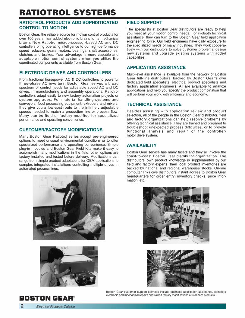
Boston Gear customer support services include technical application assistance, completeelectronic and mechanical repairs and skilled factory modifications of standard products.

Electrical Products Catalog 3
TABLE OF CONTENTS
INTRODUCTION...............................................................................................................1-2
PRODUCT SELECTION/REFERENCE GUIDE ...............................................................3-6
NONREGENERATIVE AND REGENERATIVE, DC CONTROLLERS...........................7-37
OPTIONS AND MODIFICATIONS FOR DC CONTROLLERS.....................................38-46
ACCESSORIES ............................................................................................................47-53
CLUTCHES AND BRAKES..........................................................................................55-80
MOTOR ENCLOSURES ....................................................................................................81
DC MOTORS ................................................................................................................83-91
AC MOTORS ..............................................................................................................93-109
WASHDOWN PRODUCTS .......................................................................................111-112
APPLICATION ENGINEERING ................................................................................113-127
TERMS AND CONDITIONS .....................................................................................128-129
BOSTON GEAR®, RATIOTROL®, RATIOPAX®, ACE®, DCX® and DCXplus® are registeredtrademarks of Boston Gear.

4 Electrical Products Catalog
PRODUCT SELECTION/REFERENCE GUIDE
DC Controllers, Single Phase, NonregenerativeRatiopax DCX BETA II
Pages 9-10 Pages 11-15 Pages 16-20BETAplus VEplus
Pages 21-25 Pages 26-30
DC Controllers, Single-Phase, RegenerativeRBA/VEA-RG
Pages 31-37

Electrical Products Catalog 5
PRODUCT SELECTION/REFERENCE GUIDE
AccessoriesRemote Tachometer Magnetic Analog DigitalStations Generator Pick-up Meter Meter
Pages 47-48 Pages 49-50 Page 51 Page 52 Page 52
Clutches and BrakesDC C-Face DC Foot Mounted DC Shaft Mounted AC C-Face AC C-Face AC Motor
Washdown Brake Kit
Page 57-58 Page 59-62 Pages 63-76 Page 77 Pages 78-79 Page 80
DC MotorsPermanent Permanent Shunt WoundMagnet Magnet-Washdown
Pages 86-87 Page 88 Pages 89-91
AC MotorsOpen Dripproof Totally Washdown Brake Motors Rigid Base Inverter Duty
Enclosed
Pages 95-96 Page 97-102 Page 103 Pages 104-105 Page 107 Pages 108-109

6 Electrical Products Catalog
RATIOTROL SYSTEMSSystem SelectionThe proper selection of a Ratiotrol system is based on first determining the load torque, second, the horsepower of the motor and last,the type and configuration of the controller to power the selected motor. Sizing an adjustable speed drive generally is no different thanselecting a motor and reducer for a constant speed application. Maximum RPM and maximum torque are used in all calculationsinvolving constant torque applications, which are the most common. Our standard Ratiotrol systems are constant torque drives andtherefore, selection is straight forward.Constant horsepower applications, typically winders or machine tools, require the use of the maximum load torque (usually at theminimum speed) in selecting a suitable drive. If the required constant HP value is known, the required system HP is equal to therequired speed range ratio multiplied by the constant HP figure.NOTE: Auxiliary drives beyond the reducer output shaft can reduce the cost of a system significantly since a chain or gear drivemultiplies the torque delivered by the reducer, thereby reducing the load required to be driven by the reducer. For instance, if a 3:1 ratiochain drive can be incorporated in a drive train, the driven load (torque) can be divided by 3 and the load speed multiplied by 3 beforeselecting a suitable motor and reducer combination.
SELECTION PROCEDURE:1) Select a reducer as you would for a constant speed application and size the motor/controller package to provide the HP indicated
by the reducer’s input HP rating.Note: When using compound worm gear reducers with ratios greater than 200:1, use a motor with twice the HP shown for that
reducer. This technique will provide sufficient starting torque at low motor speeds to overcome the near-static friction conditionspresent in the output bearings and gearing of the reducer.
2) The motor selected in Step 1 determines the “System HP” to use when you progress to the Ratiotrol System Selection Guides.3) From the Selection Guide, proceed to the appropriate AC or DC Controller section to determine the complete motor and controller
catalog numbers, options and any desired accessories.
*Basic DC Motor Catalog number, refer to Pages 86-87 for complete motor selection.
SINGLE PHASE DC CONTROLLER SELECTION GUIDELine
System Voltage Nonregenerative Regenerative Motor Series*HP (VAC) Ratiopax DCX BETA II BETAplus VEplus RBA-RG VEA-RG PM Shunt
1/12 115 • • BPM/PM908T —1/6 115 • • • • • • • PM916 V916001/4 115 • • • • • • • PM925 V925001/3 115 • • • • • • • PM933 V93300
115 • • • • • • • PM950 V950001/2
230 • • • • • • • PM1850 —115 • • • • • • PM975 V97500
3/4 230 • • • • • • • PM1875 V18750115 • • • • • • PM9100 V91000
1230 • • • • • • • PM18100 V18100
1-1/2 230 • • • • • • PM18150 V181502 230 • • • • • • PM18200 V182003 230 • • • • • • PM18300 183005 230 • • PM18500 18500
Electrical Products Catalog 7
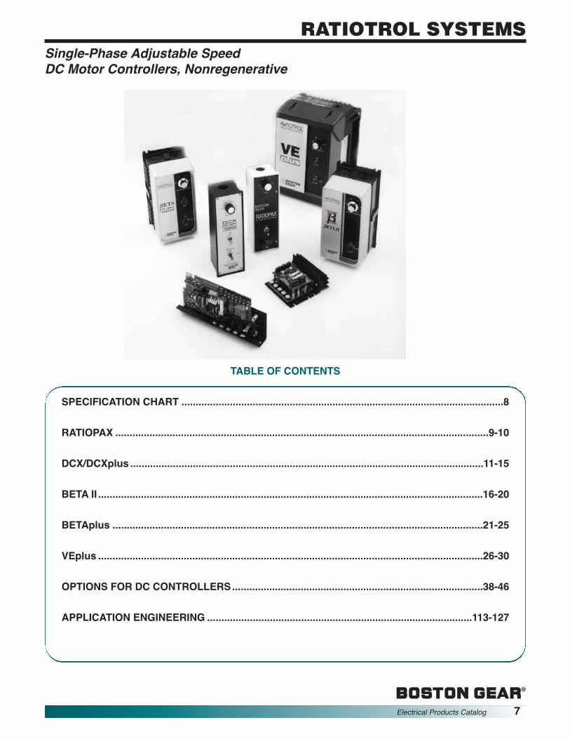
RATIOTROL SYSTEMSSingle-Phase Adjustable SpeedDC Motor Controllers, Nonregenerative
TABLE OF CONTENTS
SPECIFICATION CHART .................................................................................................................8
RATIOPAX ...................................................................................................................................9-10
DCX/DCXplus ............................................................................................................................11-15
BETA II .......................................................................................................................................16-20
BETAplus ..................................................................................................................................21-25
VEplus .......................................................................................................................................26-30
OPTIONS FOR DC CONTROLLERS........................................................................................38-46
APPLICATION ENGINEERING .............................................................................................113-127

8 Electrical Products Catalog
RATIOTROL SYSTEMS
SINGLE PHASE NONREGENERATIVE DC MOTOR CONTROLLER SPECIFICATIONS
The purpose of this chart is to provide a general feature comparison of the Boston Gear controllers. When selecting, refer to thespecific catalog selection for complete information.
S-Standard O-Optional
Single-Phase Adjustable Speed SpecificationDC Motor Controllers, Nonregenerative Chart
Features Ratiopax DCX DCXplus BETA II BETAplus VEplusAC Line Voltage 115 230 115 230 115 230 115 230 115 230 115 23050/60 HzRange Maximum Horsepower 1/2 1 1 3 1/2 1 1 3 1 3 1 5
Armature Voltage (0 to) 90 180 90 180 90 180 90 180 90 180 90 180Output Field Voltage 50 100 100 200 100 200 50/ 100/ 50/ 100/ 50/ 100/
100 200 100 200 100 200AC Line Fuse S O S S S SProtection Circuit Breaker OFunctions Jog S S S
Preset SpeedsArmature Contactor
Unidirectional W/ D.B. O S S SReversing W/DB O S S SReversing, Switch S S S S S
Constant Torque Operation S S S S S SEnclosure Angle Bracket Chassis S S S
Open Chassis S S SNEMA 1 S SNEMA 3NEMA 4 S S SNEMA 12 S S S S
Adjustments Acceleration (Seconds) 0.8-10 0.8-10 0.2-40 0.2-30 0.2-30Deceleration (Seconds) 0.8-10 0.8-10 0.2-40 0.2-30 0.2-30IR Compensation (%) 0-100 0-100 0-100 0-100 0-100Maximum Speed (%) 75-100 60-100 60-100 50-100 50-100 50-100Minimum Speed (%) 0-40 0-40 0-40 0-40 0-40Current Limit (%) 150 0-150 0-150 0-150 0-150 0-150
Horsepower/ Trim Pot Adjustments S SVoltage Resistance Wire SCalibration Reconnectable Jumpers S S S
Dip Switches S S SIsolated Regulator O S S SLoad Monitor S SSpeed Standard IR FeedbackRegulation Percentage 5% 2% 2% 2% 2% 2%
Speed Range 20:1 30:1 30:1 50:1 50:1 50:1Tachometer Feedback
Percentage 1% 1% 0.5% 0.5% 0.5%Speed Range 100:1 100:1 200:1 200:1 200:1
Input Analog S S S S S STachometer Unidirectional S S S S SFeedback Bidirectional O O OModifiable DC Tachometer Feedback S S S S SFeatures AC Line Starting S S S S S
Torque Regulator S S SExternal DC Signal Follower S S SLimit Switch Reversing S S S
Options Field Installed O O O OFactory Installed O O
UL/cUL S S S S S
Pages 9-10 11-15 11-15 16-20 21-25 26-30

SPEED REGULATION CHARACTERISTICSVariables
FieldLoad Line Heating
Regulation Change Voltage Cold/ Temp. SpeedMethod 95% ±10% Normal ±10°C Range
StandardVoltage 5% ±1% 5–12% ±2% 20:1Feedback with IRCompensation
Ratiopax Controllers are economical, non-modifiable, general purpose controllersfeaturing static conversion of AC line power to regulated DC for nonregenerative,adjustable speed armature control of shunt-wound and permanent-magnet DCmotors. Their lightweight and compact design makes these units an ideal choice for abroad range of industrial applications.
Motors suitable for application with these controllers are listed in the DC motorsection.
1. Enclosure – All models are furnished in a rugged diecast enclosure. Complete control assembly is attachedto the front cover which can be removed from theenclosure by removing four (4) screws.
2. Operator Controls – Mounted on the front cover.Included is a calibrated SPEED control potentiometerand a RUN-STOP toggle switch. A Forward-Stop-Reverse maintained switch is standard on the RP1R &RP2R. This switch includes a no pass through centerdetent which provides anti-plug protection.
3. AC Line Protection – AC line fuse providesinstantaneous protection from peak loads and faultcurrents. The fuse is front panel mounted, and can bereplaced without removing the cover.
4. Voltage Transient Protection – Suppression networkto minimize the effect of high voltage or high frequencyspikes.
5. Full-Wave Power Conversion – 2 SCRs 2 diodesand a free-wheeling diode provide optimum form factorfor best motor performance and longevity. NEMA CodeK Converter.
6. Reference Circuit – 24 VDC regulated to providestable performance with changes in line voltage.
7. Maximum Speed Adjustment – Adjustable from 75 to100% of motor base speed.
8. Trigger Circuit – Fast rise, hard firing type to minimizedi/dt degradation of SCRs.
9. Counter EMF Voltage Feedback with IR Compen-sation – Non-adjustable, factory set.
10. Quality Features – FR4 glass printed circuit card •Rugged construction • Conservatively rated com-ponents selected for long service life.
DESIGN FEATURES AND FUNCTIONS PERFORMANCE CHARACTERISTICS1. Controlled Speed Range – Zero to motor base speed.
Speed range with respect to specified regulation is shownbelow.
2. Speed Regulation – Regulation percentages listed are ofmotor base speed under steady-state conditions. Normaloperation will result in performance equal to or better thanspecifications.
3. Efficiency (rated speed/rated load)(a) Controller (SCR regulator) .....................................98%(b) Complete drive (controller and motor, typical).......85%4. Current Limit (factory set, nonadjustable)................150%
full-load torque (typical)
OPERATING CONDITIONS1. Line Voltage Variation ................................±10% of rated2. Line Frequency Variation........................................±2 Hz3. Ambient Temperature ..........0°C to 40°C (32°F to 104°F)4. Altitude (standard).....3300 feet (1000 meters) maximum
RATINGS1. Service factor ...............................................................1.02. Duty ................................................................. Continuous3. Overload Capacity ...............................150% for 1 minute4. Run Speed Potentiometer .....................100K Ohms, 2W5. Reference Power Supply .................................... 24 VDC6. AC Line Fuse, Interrupting Capacity ........... 5000 Amps7. RP1, RP1R Controllers .................115 VAC, 50 or 60 Hz,
Single Phase8. RP2, RP2R Controllers ................ 230 VAC, 50 or 60 Hz,
Single Phase
Single-Phase Adjustable Speed RATIOPAX SeriesDC Motor Controllers, Nonregenerative 1/12-1 Horsepower
Electrical Products Catalog 9
RATIOTROL SYSTEMS

10 Electrical Products Catalog
RATIOTROL SYSTEMS
DIMENSIONS – ALL MODELS
2.06
1.12 DIA.(ONE END)
1.503.00
1.62
.69
7.50
.75
(2) .19 DIA.HOLES-ASSHOWN
9.00
.88 MAX.CONTROL PROJ.
3.003.00
NEMA 1 ENCLOSED CONTROLLER WITH INTEGRAL OPERATOR CONTROLSHorsepower Range Catalog Item
115 VAC 230 VAC Number Code Function
1/6 – 1/2 —RP1 63370 Run/StopRP1R 63372 Armature Switch Reversing
— 1/2 – 1RP2 63371 Run/StopRP2R 63373 Armature Switch Reversing
APPROX WEIGHT – 2 LBS
MODEL TYPESRatiopax controllers are offered as four standard models. Models RP1 and RP2, are unidirectional packaged controllers andModels RP1R and RP2R, are reversible controllers with Forward-Stop-Reverse switch. All are furnished in a totally-enclosed, non-ventilated, rugged, die-cast aluminum alloy enclosure with integral operator controls.
ORDER BY CATALOG NUMBER OR ITEM CODE
Single-Phase Adjustable Speed RATIOPAX SeriesDC Motor Controllers, Nonregenerative 1/12-1 Horsepower
RatingsRated Horsepower (HP) 1/6 1/4 1/3 1/2 3/4 1Rated Kilowatts (kW) 0.124 0.187 0.249 0.373 0.560 0.746
115V 3.9 5.0 6.0 8.7 — —1-Phase Line UnitAC Input Amps 230V — — — 4.2 5.9 8.8(Full-Load) Unit
KVA .48 .58 .71 1.0 1.4 2.0Motor 90V 2.0 2.8 3.5 5.4 — —
ArmatureDC Output Amps 180V — — — 2.6 3.8 5.5(Full-Load) Motor(1) 50V 2.0 2.0 2.0 2.0 — —
FieldAmps 100V — — — 2.0 2.0 2.0
Full-Load Torque(lb-ft) with 1750 RPM 0.5 0.75 1.0 1.5 2.2 3.0Base Speed Motors
TYPICAL APPLICATION DATA
(1) Does not apply to permanent magnet motors.

Ratiotrol DCX® controllers statically convert single-phase AC line power to regulatedDC for nonregenerative adjustable speed armature control of shunt-wound andpermanent magnet DC motors. They are ideal for simple MRO modifications ofexisting drives or for installation in OEM equipment to provide variable speed motoroperation with traditional Boston Gear reliability.These controls feature a number of exclusive advantages. Their built-in adjustmenttrimpots, for example, offer immediate access to a broad range of horsepower settings.They completely eliminate the need to stock a variety of components for everyhorsepower rating.The dual voltage models can be connected to either 115 VAC or 230 VAC foroperation without the use of jumpers or switches.With a selection of four enclosed models, two panel-front models for installation inOEM control cabinets, and three chassis models with up to 3 horsepower capabilityand companion optional accessories, Boston Gear has a low-cost controller suitablefor virtually any requirement.Motors suitable for application with these controllers are listed in the DC motorsection.
1. DCXplus® Enclosed Models – These units arefurnished in a compact, die cast aluminum, non-ventilated NEMA 1 or NEMA 12 rated enclosure. Thecomplete control assembly is mounted on the frontpanel which can be removed from the enclosure byremoving four (4) screws. The unenclosed panelassembly can be mounted through a cut-out in theuser's enclosure.
2. DCX® Chassis Models – The units are furnished as avery compact open chassis consisting of the regula-tor/power conversion circuit board mounted to a formedaluminum chassis. The DCX202C model may befurnished with a supplemental heatsink (DCX-HTSK orDCX-RHTSK) to improve heat dissipation and therebyextend the horsepower range. Chassis units are dimen-sionally interchangeable with many competitive units.
3. Full-Wave Power Conversion – NEMA Code Kconverter configuration formed of discrete devicesrated 600 PIV. Converter consists of two (2) SCR’s, twodiodes and a free wheeling diode which provideoptimum form factor for best motor performance andlong service. Enclosed models use the controlenclosure as an integral heatsink with the power controldevices electrically isolated from the enclosure.
4. Voltage Transient Protection – Metal oxidesuppressor across the AC line minimizes the effect ofhigh voltage spikes from the AC power source.
5. Tachometer Feedback – All standard units exceptDCX102C accept a 35, 50 or 100 VDC/1000 RPMfeedback signal from a motor mounted DC tachometergenerator for improved speed regulation.(Unidirectional units only).
6. Horsepower Selection – Easily calibrated by built-intrimpots to suit individual motor horsepower ratingswithout special instruments, or plug-in shunts.
7. Wiring Terminals – Enclosed models are providedwith barrier terminal strips for all external power andsignal wires. Chassis models are provided with maletab wiring connectors. A terminal strip is offered asOptions DCX-BTB2 or DCX-BTB3.
8. AC Line Fuse – Enclosed models include an AC line fusemounted on the circuit board. Chassis units do not includea fuse as standard, but a fuse holder may be providedwith Options DCX-BTB2, DCX-BTB3 or DCX-FBK.
9. Operator Controls – All enclosed models includeintegral operator controls consisting of a speed settingpotentiometer and an ON-OFF AC line power switch.Switch is maintained in ON and OFF positions.Reversing models additionally include a 3-positionFORWARD-STOP-REVERSE maintained switch.Switch includes a no pass through center detent whichprovides a delay when changing direction.Chassis units are controlled by external, customer fur-nished switches, pushbuttons, or control logic. Theseunits include an inhibit circuit for automatic operation byswitch, relay or PLC.Chassis units are furnished with a speed setting poten-tiometer and female wiring connectors supplied loose.
10. Line Voltage Selection – Line voltage selection isautomatic without the use of jumpers or switches.
11. Field Supply – A full-wave, transient protected motorfield supply is provided.
12. UL Rating – The DCX Series units are either UL listedor UL recognized.
DESIGN FEATURES AND FUNCTIONS
Single-Phase Adjustable Speed DCX® SeriesDC Motor Controllers, Nonregenerative DCXplus® Series
1/12-3 Horsepower
Electrical Products Catalog 11
RATIOTROL SYSTEMS

12 Electrical Products Catalog
RATIOTROL SYSTEMS
RATINGS1. Horsepower. . . See selection chart Page 62. Service Factor ..............................................................1.03. Duty ................................................................. Continuous4. Operating Voltages
5. Overload Capacity (armature) .............150% for 1 minute6. Run Speed Potentiometer .................... 5K Ohms, 1/2 W7. Reference Power Supply...................................10VDC(1)8. Line Fuse(2) ......................................... Provided by others
(1) Units are optionally adaptable for use with 4-20mA and 0-10 VDCreference voltages by the use of option DCX-25A
(2) Line fuse is standard on DCXplus models, optional on all others
PERFORMANCE CHARACTERISTICS1. Controlled Speed Range — Zero to motor base speed.
Speed range with respect to specified regulation is shownon right.
2. Speed Regulation — Regulation percentages listed areof motor base speed under steady-state conditions.Normal operation will result in performance equal to orbetter than specifications.
(1) Unidirectional models only.
3. Efficiency (Rated speed/rated load)Controller ................................................................... 99%Controller and Motor (typical) ................................. 85%
ADJUSTMENTS1. Current Limit.................. 0-150% full-load torque (typical)2. Maximum Speed .............. 60-100% of motor base speed3. Minimum Speed ................... 0-40% of motor base speed4. IR (load) Compensation ................. 0-100% of rated load5. Acceleration/Deceleration(1) .................. 0.8-10 seconds
NOTE: (1) DCX102C acceleration/deceleration is 1.0 second fixed rate.
OPERATING CONDITIONS1. Line Voltage Variation ............................... ±10% of rated2. Line Frequency Variation ....................................... ±2 Hz3. Ambient TemperatureChassis .................................... 0°C to 50°C (32°F to 122°F)Enclosed .................................. 0°C to 40°C (32°F to 104°F)4. Altitude (Standard).... 3300 Feet (1000 meters) maximum5. Relative Humidity ........................... 95% non-condensing
Power Source Output VDC(Single-Phase) Armature Field
115V, 50 or 60 Hz 0-90 100230V, 50 or 60 Hz 0-180 200
VariableRegulation Load Line SpeedMethod Change Voltage Field Heating Temp. Range
95% ± 10% Cold/Normal ±10°CStandard VoltageFeedback with IR 2% ± 1% 5–12% ± 2% 30:1CompensationTachometerFeedback(1) 1% ± 1% 0.2% ±2% 100:1
SPEED REGULATION CHARACTERISTICS
OPERATING VOLTAGES
RatingsRated Horsepower (HP) 1/12 1/6 1/4 1/3 1/2 3/4 1 1-1/2 2 3Rated Kilowatts (kW) 0.062 0.124 0.187 0.249 0.373 0.560 0.746 1.129 1.492 2.238
115V 2.0 3.9 5.0 6.0 8.7 12.4 15.0 — — —1-Phase Line UnitAC Input Amps 230V — — — — 4.8 5.9 8.8 12.6 15.8 24.0(Full-Load) Unit
KVA .30 .48 .58 .71 1.0 1.4 2.0 3.0 4.0 6.0Motor 90V 0.9 2.0 2.8 3.5 5.4 8.1 10.5 — — —
Armature
DC OutputAmps 180V — — — — 2.5 3.8 5.5 8.2 11.6 16.0
(Full-Load) Motor(1) 100V 1.0 1.0 1.0 1.0 1.0 1.0 1.0 — — —FieldAmps 200V — — — — 1.0 1.0 1.0 1.0 1.0 1.0
Full-Load Torque(lb-ft) with 1750 RPM .25 0.5 0.75 1.0 1.5 2.2 3.0 4.5 6.0 9.0Base Speed Motors
TYPICAL APPLICATION DATA
(1) Does not apply to permanent magnet motors.
Single-Phase Adjustable Speed DCX® SeriesDC Motor Controllers, Nonregenerative DCXplus® Series
1/12-3 Horsepower

MODEL TYPES
DCX and DCXplus Series controllers are offered as open chassis or enclosed configurations in nine (9) standard models in four (4)functional groups. The DCX® Series chassis units are ideal for the OEM or panel builder who may want to build a custom system byintegrating the controller in an enclosure with special logic or auxiliary control devices. The DCXplus® Series enclosed units areoffered as complete self-contained functional packages which include power conversion and regulator electronics, AC lineprotection and integral operator controls.
1/12 – 1/2 — DCX102C 65984 Run/Stop(3)(2)
1/12 – 1/2 1/2 – 1 DCX202C 65985 Run/Stop(3)(2)1/12 – 1(1) 1/2 – 2(1)
1/12 – 1 1/2 – 3 DCX302C 65986 Run/Stop(3)(2)
Horsepower Range(4) Catalog Item115 VAC 230 VAC Number Code Function
(1) Requires either Option DC-RHTSK for 1 HP on 115 VAC and 2 HP on 230 VAC or Option DCX-HTSK for 3/4 HP on 115 VAC and 1-1/2 HP on 230 VAC.(2) DC units are furnished with a potentiometer rated 5K ohms, 1/2 watt for separate mounting.(3) Armature contactor Run-Stop-DB, and contactor reversing and dynamic braking are provided by Options DCX-DA and DCX-RA(4) Units may be easily recalibrated for any standard rating within the range of the product using trimpots.
DCX® AND DCXplus® SERIES SELECTION CHARTORDER BY CATALOG NUMBER OR ITEM CODE
DIMENSIONS - DCX CHASSIS
DCX102C, DCX202C DCX302C
DCXplus FRONT PANEL ASSEMBLY WITH INTEGRAL OPERATOR CONTROLS
DCX ANGLE BRACKET CHASSIS CONTROLLERS
1/12 – 1/2 1/2 – 1DCX202EP 65987 Run/StopDCX202ERP 65991 Run/Stop, Armature Switch Reversing
DCXplus NEMA 1 ENCLOSED CONTROLLER WITH INTEGRAL OPERATOR CONTROLS
1/12 – 1/2 1/2 – 1DCX202E 65988 Run/StopDCX202ER 65992 Run/Stop, Armature Switch Reversing
DCXplus NEMA 12 ENCLOSED CONTROLLER WITH INTEGRAL OPERATOR CONTROLS
1/12 – 1/2 1/2 – 1DCX202EN12 65990 Run/StopDCX202ERN12 65995 Run/Stop, Armature Switch Reversing
Single-Phase Adjustable Speed DCX® SeriesDC Motor Controllers, Nonregenerative DCXplus® Series
1/12-3 Horsepower
4.253.69 .28
1.31.41
.188 TYP.41
.750
2.503.56
6.881.75
.188TYP.
5.188
.28
6.00 .44
.44
5.75
1.12
.44
Electrical Products Catalog 13
RATIOTROL SYSTEMS

14 Electrical Products Catalog
RATIOTROL SYSTEMS
DIMENSIONS - HEATSINKS
DCX RHTSK DCX HTSK
Single-Phase Adjustable Speed DCX® SeriesDC Motor Controllers, Nonregenerative DCXplus® Series
1/12-3 Horsepower
2.00
#6-32 TAP, 2 PLACES
.
6.15.700
4.4303.000
2.00
1.38
#6-32 TAP, 2 PLACES
.900
.25 3.7504.25
5.756.150
6.75.700
4.4303.000
.87 .250
2.375 .18.75
.156 DIA4 PLACES
2.752.72
8.72
8.360
.69 1.625 .75.62
1.12 DIA.ONE END
.19 DIA MOUNTING HOLES2 PLACES ON BACK
3.003.00
9.00
7.500
2.06
.62
.19 DIA HOLES3 PLACES
3.123.00
9.00
1.12 DIA.ONE END 2.06
1.875.56
10.25
9.500
1.50
.12
.75 TYP
DIMENSIONS - DCXplus ENCLOSED
DCXplus NEMA 1 DCXplus NEMA12 DCXplus Panel–Front
OPTIONS FOR DCX SERIES CHASSIS UNITSORDER BY CATALOG NUMBER OR ITEM CODE
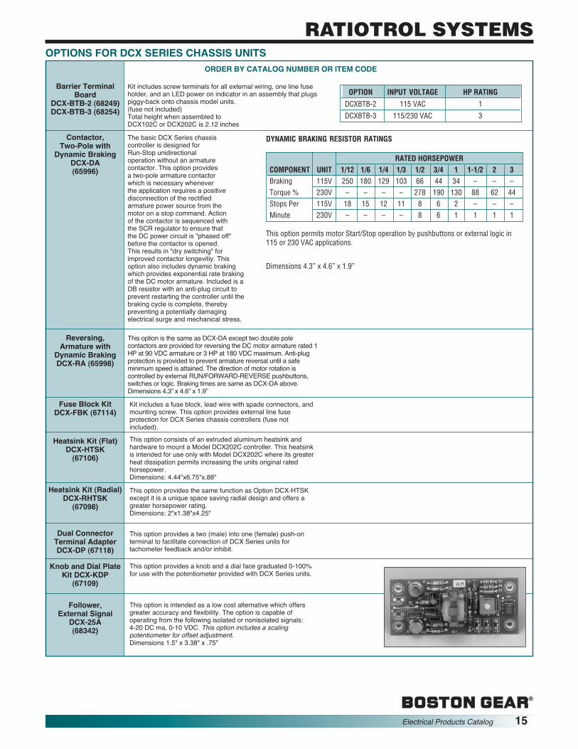
Kit includes screw terminals for all external wiring, one line fuseholder, and an LED power on indicator in an assembly that plugspiggy-back onto chassis model units.(fuse not included)Total height when assembled toDCX102C or DCX202C is 2.12 inches
The basic DCX Series chassiscontroller is designed forRun-Stop unidirectionaloperation without an armaturecontactor. This option providesa two-pole armature contactorwhich is necessary wheneverthe application requires a positivedisconnection of the rectifiedarmature power source from themotor on a stop command. Actionof the contactor is sequenced withthe SCR regulator to ensure thatthe DC power circuit is "phased off"before the contactor is opened.This results in "dry switching" forimproved contactor longevitiy. Thisoption also includes dynamic brakingwhich provides exponential rate brakingof the DC motor armature. Included is aDB resistor with an anti-plug circuit toprevent restarting the controller until thebraking cycle is complete, therebypreventing a potentially damagingelectrical surge and mechanical stress.
This option is the same as DCX-DA except two double polecontactors are provided for reversing the DC motor armature rated 1HP at 90 VDC armature or 3 HP at 180 VDC maximum. Anti-plugprotection is provided to prevent armature reversal until a safeminimum speed is attained. The direction of motor rotation iscontrolled by external RUN/FORWARD-REVERSE pushbuttons,switches or logic. Braking times are same as DCX-DA above.Dimensions 4.3” x 4.6” x 1.9”
Kit includes a fuse block, lead wire with spade connectors, andmounting screw. This option provides external line fuseprotection for DCX Series chassis controllers (fuse notincluded).
This option consists of an extruded aluminum heatsink andhardware to mount a Model DCX202C controller. This heatsinkis intended for use only with Model DCX202C where its greaterheat dissipation permits increasing the units original ratedhorsepower.Dimensions: 4.44"x6.75"x.88"
This option provides the same function as Option DCX-HTSKexcept it is a unique space saving radial design and offers agreater horsepower rating.Dimensions: 2"x1.38"x4.25"
This option provides a two (male) into one (female) push-onterminal to facilitate connection of DCX Series units fortachometer feedback and/or inhibit.
This option provides a knob and a dial face graduated 0-100%for use with the potentiometer provided with DCX Series units.
This option is intended as a low cost alternative which offersgreater accuracy and flexibility. The option is capable ofoperating from the following isolated or nonisolated signals:4-20 DC ma, 0-10 VDC. This option includes a scalingpotentiometer for offset adjustment.Dimensions 1.5" x 3.38" x .75"
Barrier TerminalBoard
DCX-BTB-2 (68249)DCX-BTB-3 (68254)
Contactor,Two-Pole with
Dynamic BrakingDCX-DA(65996)
Reversing,Armature with
Dynamic BrakingDCX-RA (65998)
Fuse Block KitDCX-FBK (67114)
Heatsink Kit (Flat)DCX-HTSK(67106)
Heatsink Kit (Radial)DCX-RHTSK(67098)
Dual ConnectorTerminal AdapterDCX-DP (67118)
Knob and Dial PlateKit DCX-KDP(67109)
Follower,External Signal
DCX-25A(68342)
OPTION INPUT VOLTAGE HP RATING
DCXBTB-2 115 VAC 1
DCXBTB-3 115/230 VAC 3
RATED HORSEPOWERCOMPONENT UNIT 1/12 1/6 1/4 1/3 1/2 3/4 1 1-1/2 2 3Braking 115V 250 180 129 103 66 44 34 – – –Torque % 230V – – – – 278 190 130 88 62 44Stops Per 115V 18 15 12 11 8 6 2 – – –Minute 230V – – – – 8 6 1 1 1 1
DYNAMIC BRAKING RESISTOR RATINGS
This option permits motor Start/Stop operation by pushbuttons or external logic in115 or 230 VAC applications.
Dimensions 4.3” x 4.6” x 1.9”
Electrical Products Catalog 15
RATIOTROL SYSTEMS
16 Electrical Products Catalog
RATIOTROL SYSTEMS
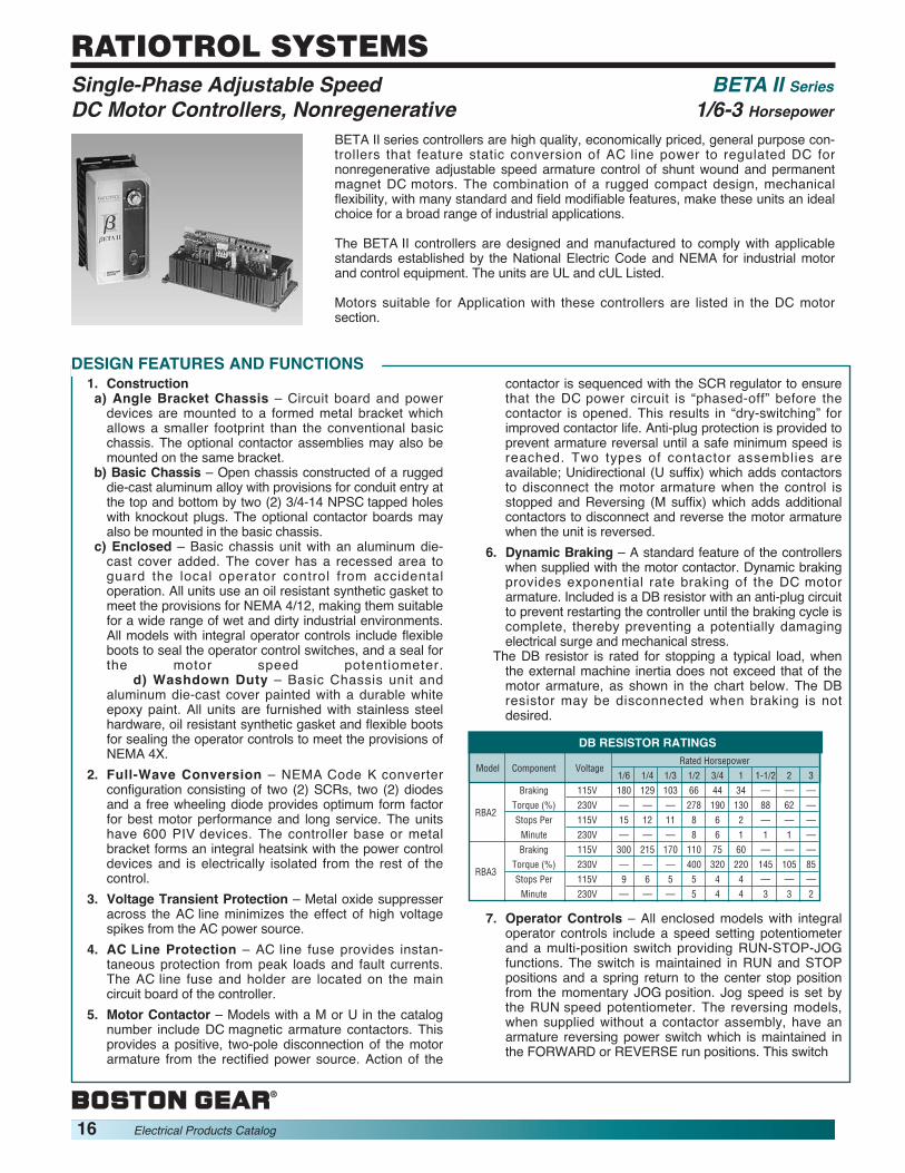
BETA II series controllers are high quality, economically priced, general purpose con-trollers that feature static conversion of AC line power to regulated DC fornonregenerative adjustable speed armature control of shunt wound and permanentmagnet DC motors. The combination of a rugged compact design, mechanicalflexibility, with many standard and field modifiable features, make these units an idealchoice for a broad range of industrial applications.
The BETA II controllers are designed and manufactured to comply with applicablestandards established by the National Electric Code and NEMA for industrial motorand control equipment. The units are UL and cUL Listed.
Motors suitable for Application with these controllers are listed in the DC motorsection.
1. Constructiona) Angle Bracket Chassis – Circuit board and power
devices are mounted to a formed metal bracket whichallows a smaller footprint than the conventional basicchassis. The optional contactor assemblies may also bemounted on the same bracket.
b) Basic Chassis – Open chassis constructed of a ruggeddie-cast aluminum alloy with provisions for conduit entry atthe top and bottom by two (2) 3/4-14 NPSC tapped holeswith knockout plugs. The optional contactor boards mayalso be mounted in the basic chassis.
c) Enclosed – Basic chassis unit with an aluminum die-cast cover added. The cover has a recessed area toguard the local operator control from accidentaloperation. All units use an oil resistant synthetic gasket tomeet the provisions for NEMA 4/12, making them suitablefor a wide range of wet and dirty industrial environments.All models with integral operator controls include flexibleboots to seal the operator control switches, and a seal forthe motor speed potentiometer.
d) Washdown Duty – Basic Chassis unit andaluminum die-cast cover painted with a durable whiteepoxy paint. All units are furnished with stainless steelhardware, oil resistant synthetic gasket and flexible bootsfor sealing the operator controls to meet the provisions ofNEMA 4X.
2. Full-Wave Conversion – NEMA Code K converterconfiguration consisting of two (2) SCRs, two (2) diodesand a free wheeling diode provides optimum form factorfor best motor performance and long service. The unitshave 600 PIV devices. The controller base or metalbracket forms an integral heatsink with the power controldevices and is electrically isolated from the rest of thecontrol.
3. Voltage Transient Protection – Metal oxide suppresseracross the AC line minimizes the effect of high voltagespikes from the AC power source.
4. AC Line Protection – AC line fuse provides instan-taneous protection from peak loads and fault currents.The AC line fuse and holder are located on the maincircuit board of the controller.
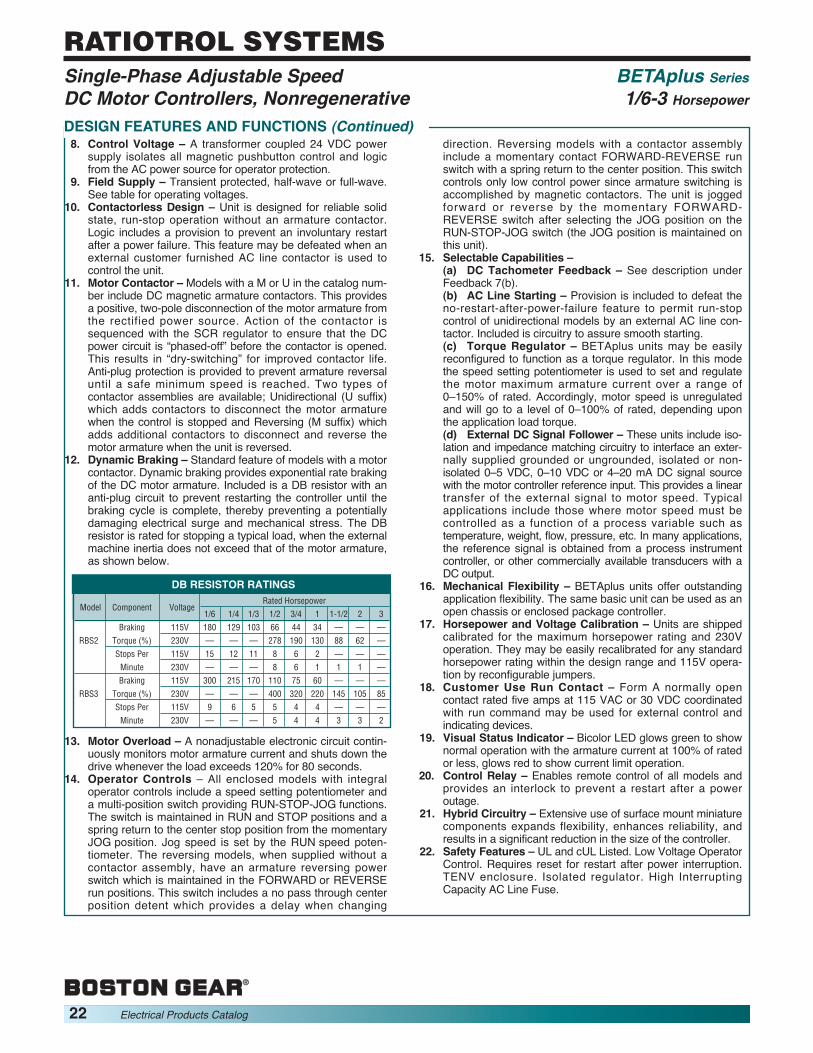
5. Motor Contactor – Models with a M or U in the catalognumber include DC magnetic armature contactors. Thisprovides a positive, two-pole disconnection of the motorarmature from the rectified power source. Action of the
contactor is sequenced with the SCR regulator to ensurethat the DC power circuit is “phased-off” before thecontactor is opened. This results in “dry-switching” forimproved contactor life. Anti-plug protection is provided toprevent armature reversal until a safe minimum speed isreached. Two types of contactor assemblies areavailable; Unidirectional (U suffix) which adds contactorsto disconnect the motor armature when the control isstopped and Reversing (M suffix) which adds additionalcontactors to disconnect and reverse the motor armaturewhen the unit is reversed.
6. Dynamic Braking – A standard feature of the controllerswhen supplied with the motor contactor. Dynamic brakingprovides exponential rate braking of the DC motorarmature. Included is a DB resistor with an anti-plug circuitto prevent restarting the controller until the braking cycle iscomplete, thereby preventing a potentially damagingelectrical surge and mechanical stress.
The DB resistor is rated for stopping a typical load, whenthe external machine inertia does not exceed that of themotor armature, as shown in the chart below. The DBresistor may be disconnected when braking is notdesired.
7. Operator Controls – All enclosed models with integraloperator controls include a speed setting potentiometerand a multi-position switch providing RUN-STOP-JOGfunctions. The switch is maintained in RUN and STOPpositions and a spring return to the center stop positionfrom the momentary JOG position. Jog speed is set bythe RUN speed potentiometer. The reversing models,when supplied without a contactor assembly, have anarmature reversing power switch which is maintained inthe FORWARD or REVERSE run positions. This switch
DESIGN FEATURES AND FUNCTIONS
Model Component VoltageRated Horsepower
1/6 1/4 1/3 1/2 3/4 1 1-1/2 2 3Braking 115V 180 129 103 66 44 34 — — —
RBA2Torque (%) 230V — — — 278 190 130 88 62 —Stops Per 115V 15 12 11 8 6 2 — — —Minute 230V — — — 8 6 1 1 1 —Braking 115V 300 215 170 110 75 60 — — —
RBA3Torque (%) 230V — — — 400 320 220 145 105 85Stops Per 115V 9 6 5 5 4 4 — — —Minute 230V — — — 5 4 4 3 3 2
DB RESISTOR RATINGS
Single-Phase Adjustable Speed BETA II SeriesDC Motor Controllers, Nonregenerative 1/6-3 Horsepower

includes a no pass through center detent which provides adelay when changing direction for anti-plug protection.
Reversing models with a contactor assembly include amomentary contact FORWARD-REVERSE run switchwith a spring return to the center position. This switchcontrols only low control power since armature switchingis accomplished by magnetic contactors. The unit isjogged forward or reverse by the momentaryFORWARD-REVERSE switch after selecting the JOGposition on the RUN-STOP-JOG switch (the JOGposition is maintained on this unit).
8. Control Transformer – All models include a controltransformer which provides internal reference andpower supply voltages, and a low voltage source for themagnetic controls, control logic and operator controls.
9. Counter EMF Voltage Feedback with IR Compensa-tion – Adjustable to suit individual motor characteristics.
10. Trigger Circuit – Fast rise, hard firing to ensure reliableconduction and minimize di/dt degradation of SCRs.
11. Field Supply – Transient protected. Selectable foreither half-wave or full-wave output. See Table foroperating voltages.
12. Control Relay – Enables remote control of all modelsand provides an interlock to prevent a restart after apower outage. This may be defeated when an externalcustomer furnished AC line contactor is used to controlthe unit.
13. Customer Use Run Relay Contact – Form A normallyopen contact rated five (5) amps at 115 VAC or 30 VDCcoordinating with a run command. May be used forexternal control and indicating devices. May also beapplied as a pushbutton seal-in or a drive OK contact.
14. Hybrid Circuitry – Miniature components in customsurface mount assemblies improve reliability and makeavailable more features in the smallest possiblemechanical configuration.
15. Selectable Capabilities –a) DC Tachometer Feedback – Provided is impedance
matching, voltage scaling and terminals for accepting a
signal from a DC tachometer generator directly coupled tothe drive motor armature. The tachometer signal makesthe controller directly sensitive to motor speed. This resultsin an expanded speed range, improved speed regulationwith load changes, motor field heating and other operatingvariables. The controller will automatically transfer tocounter EMF voltage feedback to prevent a runaway motorif the tachometer circuit is opened. (A broken tachometerdrive coupling will cause the motor to run at maximumspeed.) Tachometers producing 7 to 150 VDC atmaximum motor speed may be used. This feature issuitable for use only with unidirectional units using DCtachometers.
b) AC Line Starting – A provision is included to defeatthe no-restart-on-power-failure feature to permit run-stop control of unidirectional models by an external ACline contactor. Included is circuitry to assure smoothmotor starting.
c) Torque Regulator – These units may be easily recon-figured to function as torque regulators. In this mode, thespeed setting potentiometer is used to set and regulatethe maximum motor armature current over a range of 0 to150% of rated current. Accordingly motor speed isunregulated and will go to a level of 0 to 100% of ratedspeed, depending upon the application load torque.
16. Mechanical Flexibility – The same basic unit can beused as an open chassis or an enclosed packagecontroller. Enclosed units may be mounted under orthrough a console surface as shown on page 20. Theangle bracket chassis offers the same controller in asmaller footprint and is designed for use in thecustomer’s own panel.
17. Horsepower and Voltage Calibration – Units areshipped calibrated for the maximum horsepower ratingand 230V operation. They may be easily recalibrated for115V operation by reconfigurable jumpers and anystandard horsepower rating within the design range byclipping shunt wires.
18. Safety Features – UL, cUL listed, low voltage operatorcontrol. Requires mandatory restart after powerinterruption, NEMA 4/12.
DESIGN FEATURES AND FUNCTIONS (Continued)
RATINGS1. Horsepower Range:Enclosed...................................... 1/6 thru 1 HP @ 115 VAC
1/2 thru 2 HP @ 230 VACChassis ....................................... 1/6 thru 1 HP @ 115 VAC
1/2 thru 3 HP @ 230 VAC2. Operating Voltages
3. Service Factor ............................................................. 1.04. Duty ................................................................. Continuous5. Overload Capacity (Armature circuit) . 150% for 1 minute6. Run Speed Potentiometer ..................... 5K ohms, 1/2 W7. Reference Power Supply .....................................10 VDC8. AC Line Fuse, Interrupting Capacity ...... 100,000 Amps
ADJUSTMENTSPotentiometer adjustments are provided for:1. Acceleration Time................................... 0.2–40 seconds2. Deceleration Time ................................... 0.2–40 seconds3. Minimum Speed............................. 0–40% of base speed4. Maximum Speed ........................ 50–100% of base speed5. IR (Load) Compensation ................0–100% of rated load6. Current Limit ............................0–150% of full load torque
Output VDC Control MagneticPower Source Reference Control(Single-Phase) Armature Field(1) Voltage Voltage
115V, 50 or 60 Hz 0–90 50/100 0-10 VDC 24 VDC230V, 50 or 60 Hz 0–180 100/200 4-20 MA
OPERATING VOLTAGES
(1) Selectable
Single-Phase Adjustable Speed BETA II SeriesDC Motor Controllers, Nonregenerative 1/6-3 Horsepower
Electrical Products Catalog 17
RATIOTROL SYSTEMS

18 Electrical Products Catalog
RATIOTROL SYSTEMS
PERFORMANCE CHARACTERISTICS1. Controlled Speed Range — Zero to motor base speed.
Speed range with respect to specified regulation is shownbelow.
2. Speed Regulation — Regulation percentages listed areof motor base speed under steady-state conditions.Normal operation will result in performance equal to orbetter than specifications.
3. Efficiency — (rated speed/rated load)(a) Controller (SCR regulator).....................................99%(b) Complete drive (Controller and motor, typical).......85%
OPERATING CONDITIONS1. Line Voltage......... 115/230 VAC, 50/60 Hz, Single Phase2. Line Voltage Variation............................ ±10% of rated(1)3. Line Frequency Variation ....................................... ±2 Hz4. Ambient Temperature.....................Enclosed: 0° to 40° C
(32° to 104° F)Chassis: 0° to 55° C
(32° to 131° F)5. Altitude .......................... 3300 ft. (1000 meters) maximum6. Relative Humidity ....................... 0–95%, noncondensing
(1) Unit will operate down to -15% of rated voltage although this may preventrated speed with rated load.
Variable
Regulation Field SpeedMethod
Load Line Heating Temp. RangeChange Voltage Cold/ ±10°C95% ±10% NormalStandard VoltageFeedback with IR 2% ±1% 5-12% ±2% 50:1CompensationOptional TachometerFeedback(1) 0.5% ±1% 0.2% ±2% 200:1
(1) Unidirectional Models Only
SPEED REGULATION CHARACTERISTICS
Single-Phase Adjustable Speed BETA II SeriesDC Motor Controllers, Nonregenerative 1/6-3 Horsepower
RatingsRated Horsepower (HP) 1/6 1/4 1/3 1/2 3/4 1 1-1/2 2 3Rated Kilowatts (kW) 0.124 0.187 0.249 0.373 0.560 0.746 1.120 1.492 2.238
1-Phase Line 115 VAC 3.9 5.0 6.0 8.7 12.4 15.8 — — —AC Input Amps 230 VAC — — — 4.2 5.9 8.8 12.6 15.8 22.0(Full-Load) KVA 0.48 0.58 0.71 1.00 1.40 2.00 3.00 4.00 5.00
Motor 90V 2.0 2.8 3.5 5.4 8.1 10.5 — — —Armature
DC Output Amps 180V — — — 2.7 4.0 5.5 8.2 11.6 14.4(Full-Load)
50V 1.0 1.0 1.0 1.0 1.0 1.0 — — —100V — — — 1.0 1.0 1.0 1.0 1.0 1.0
200V — — — 1.0 1.0 1.0 1.0 1.0 1.0Full-Load Torque (lb-ft) with 1750 RPM
0.5 0.75 1.0 1.5 2.2 3.0 4.5 6.0 9.0Base Speed MotorsMinimum Transformer KVA for Voltage
0.5 0.75 0.75 1.0 1.5 2.0 3.0 5.0 7.5Matching or Isolation
TYPICAL APPLICATION DATA
MOUNTING CONFIGURATIONS
PANEL PANELPANELSURFACE
PANEL MOUNTEDOPEN CHASSIS
SURFACE MOUNTEDENCLOSED PACKAGE
THROUGH PANELSURFACE MOUNTED
BELOW PANELSURFACE MOUNTED
Motor(1)
FieldAmps
(Maximum)
(1) Does not apply to Permanent Magnet Motors

Single-Phase Adjustable Speed BETA II SeriesDC Motor Controllers, Nonregenerative 1/6-3 HorsepowerMODEL TYPESBETA II controllers are offered in twenty three (23) standard models in six functional groups. The basic chassis models are thenucleus of all the enclosed models; standard covers and contactor assemblies can be added to the basic chassis to make anenclosed controller or the enclosed unit may be ordered complete as shown below.
ANGLE BRACKET CHASSIS CONTROLLERS WITHOUT OPERATOR CONTROLS*
Horsepower Range(1)Catalog Item
115 VAC 230 VAC Number Code Function
BASIC CHASSIS CONTROLLERS WITHOUT OPERATOR CONTROLS*RBA2 64801 Run/Stop(2)
1/6 – 1 1/2 – 2 RBA2U 57831 Armature Contactor Run/Stop and DBRBA2M 64821 Armature Contactor Forward/Reverse and DBRBA3 64865 Run/Stop(2)
1/6 – 1 1/2 – 3 RBA3U 57889 Armature Contactor Run/Stop and DBRBA3M 64873 Armature Contactor Forward/Reverse and DB
NEMA 4/12 ENCLOSED CONTROLLERS WITHOUT OPERATOR CONTROLS*RBA2B 64805 Run/Stop(2)
1/6 – 1 1/2 – 2 RBA2UB 57852 Armature Contactor Run/Stop and DBRBA2MB 64855 Armature Contactor Forward/Reverse and DB
ORDER BY CATALOG NUMBER OR ITEM CODE
NEMA 4/12 ENCLOSED CONTROLLERS WITH INTEGRAL OPERATOR CONTROLSRBA2S 64814 Run/Stop/Jog(2) (4)
1/6 – 1 1/2 – 2 RBA2R 64820 Run/Stop/Jog, Armature Switch Reversing(3) (4)
RBA2US 57853 Run/Stop/Jog, Armature Contactor Run and DB(4)
RBA2MR 64863 Run/Stop/Jog, Armature Contactor Forward/Reverse and DB(5)
WASHDOWN DUTY ENCLOSED CONTROLLERS WITH INTEGRAL OPERATOR CONTROLSRBA2S-WD 13102 Run/Stop/Jog(2) (4)
1/6 – 1 1/2 – 2 RBA2R-WD 13104 Run/Stop/Jog, Armature Switch Reversing(3) (4)
RBA2US-WD 13106 Run/Stop/Jog, Armature Contactor Run and DB(4)
RBA2MR-WD 13108 Run/Stop/Jog, Armature Contactor Forward/Reverse and DB(5)
WASHDOWN DUTY ENCLOSED CONTROLLERS WITHOUT OPERATOR CONTROLS*
*Refer to Remote Operator Control Stations on Pages 47 and 48.(1) Units are shipped calibrated for the maximum horsepower ratings shown. Units may be calibrated for other standard ratings by the removal of appropriate
resistance wires. Units are connected for 230 VAC and are easily reconnected for 115 VAC input.(2) Contactorless Run-Stop Operation(3) Contactorless Reversing Operation(4) Jog Speed is set by the Run Speed Potentiometer. Maintained in RUN position, JOG position is momentary with a spring return to STOP.(5) Jog Speed is set by the Run Speed Potentiometer. Maintained JOG position, Forward/Reverse are momentary.
RBA2C 57854 Run/Stop(2)
1/6 – 1 1/2 – 2 RBA2CU 57855 Armature Contactor Run/Stop and DBRBA2CM 57856 Armature Contactor Forward/Reverse and DB
RBA2B-WD 13048 Run/Stop(2)
1/6 – 1 1/2 – 2 RBA2UB-WD 13050 Armature Contactor Run/Stop and DBRBA2MB-WD 13100 Armature Contactor Forward/Reverse and DB
RBA2UB, RBA2MBRBA2US, RBA2MR
RBA2U RBA2B, RBA2S RBA2UB-WDRBA2M RBA2R, RBA2BWD RBA2MB-WD
RBA2CU RBA2 RBA3U RBA2SWD RBA2US-WDModel RBA2C RBA2CM RBA3 RBA3M RBA2RWD RBA2MR-WD
Weight (Lbs) 2.0 2.3 3.3 3.8 5.5 6.1
CONTROLLER WEIGHTS
Electrical Products Catalog 19
RATIOTROL SYSTEMS

20 Electrical Products Catalog
RATIOTROL SYSTEMSSingle-Phase Adjustable Speed BETA II SeriesDC Motor Controllers, Nonregenerative 1/6-3 Horsepower
OPTIONSOptions and modifications are listed alpha-numerically within each group. Complete option descriptions are listed in the DC optionsection. To order a controller with the option installed or the modification made, add the option number or letter as a suffix to thecontroller catalog number, e.g. RBA2B-21. To order a kit for field installation, order by item code.
KitGroup Option No. Item Code Notes
Feedback Torque (Current) Reference 18E — (1)DC Tachometer Feedback 24 — (1)Line Starting LS — (1)Motor Speed Potentiometer, One Turn 21 — (2)
External Motor Speed Potentiometer, Ten Turn (Analog) 21A 60168 (3)Motor Speed Potentiometer, Ten Turn (Digital) 21B 66103 (3)
Notes:(1) Modifiable feature of controller(2) Unit will not be rated NEMA 4/12 unless factory installed.(3) Unit will not be rated NEMA 4/12
DIMENSIONS
9.12
9.5
4.005.00
.505.25
.19
TAP NO. 3/4-14 NPSC(2 PL)
9.12
9.5
4.00
5.00
.504.30
2.25
8.00
TAP NO. 3/4-14 NPSC(2 PL))
.19
ENCLOSED CHASSIS ANGLE BRACKET CHASSIS
RBA2C RBA2CURBA2CM
REMOTE OPERATOR CONTROL STATIONS BETA IIUse With
Catalog Item Control Elements ControllerNumber Code Pushbuttons Switches Pots ModelsRCS1 69362 Run, Stop — Motor Speed ALL
RCS3C 58098 Run, Stop Run/Jog Motor SpeedJog Speed RBA2U, RBA3U, RBA2UB
RCS3D 58099 Run, Stop Run/Jog Motor Speed RBA2, RBA3, RBA2BJog Speed
RCS6 60239 Fwd, Rev, Stop — Motor Speed RBA2M, RBA3M, RBA2MB
RCS16 58102 — Run/Stop/Jog Motor Speed RBA2U, RBA3U, RBA2UB
RCS17 58103 — Run/Stop/Jog, Motor Speed RBA2M, RBA3M, RBA2MBFwd/Rev
ORDER BY CATALOG NUMBER OR ITEM CODE
4.25 1.75 3.312
8.00
8.88
Remote Operator Station dimensions shown on page 48.

BETAplus series controllers are high performance, high quality, general purpose unitswhich feature static conversion of AC line power to regulated DC for nonregenerative,adjustable speed armature control of shunt-wound or permanent magnet DC motors.The BETAplus series features an isolated speed reference circuit and uses miniaturecomponent hybrid assemblies which provide many standard features in a compactpackage. This series incorporates the use of DIP switches and reconnectable jumpersto configure the voltage, horsepower and selectable features of the controller. Thecombination of a rugged compact design with standard features and field modificationsmake this controller an ideal choice for a broad range of industrial applications.
These controllers are designed and manufactured to comply with applicablestandards established by the National Electric Code and NEMA pertaining to motorand industrial control equipment. The controllers are UL and cUL Listed.
Motors suitable for application with these controllers are listed in the DC motorsection.
1. Constructiona) Angle Bracket Chassis – Circuit board and power devices
are mounted to formed metal bracket which allows asmaller footprint than the conventional basic chassis. Theoptional contactor assemblies may also be mounted on thesame bracket.
b) Basic Chassis – Open chassis constructed of a ruggeddie-cast aluminum alloy with provisions for conduit entry atthe top and bottom by two (2) 3/4-14 NPSC tapped holeswith knockout plugs. The optional contactor assemblies mayalso be mounted in the basic chassis.
c) Enclosed – Basic chassis unit with an aluminum die-castcover added. The cover has a recessed area to guard thelocal operator control from accidental operation. All unitsuse an oil resistant synthetic gasket to meet the provisionsfor NEMA 4/12, making them suitable for a wide range ofwet and dirty environments. All models with integraloperator controls include flexible boots to seal the operatorcontrol switches, and a seal for the motor speedpotentiometer.
d) Washdown Duty – Basic chassis unit and aluminum die-cast cover painted with a durable white epoxy paint. Allunits are furnished with stainless steel hardware, oilresistant synthetic gasket and flexible boots for sealing theoperator controls to meet the provisions of NEMA 4X.
2. Full-Wave Power Conversion – Full-wave converterconfiguration consisting of four SCR's and a freewheelingdiode provide benefits for optimum motor performance andlong service. Power bridge is composed of 600PIV, discrete,encapsulated and electrically isolated devices. The alloybase forms an integral heatsink with the power controldevices electrically isolated from the base.
The "full-bridge” configuration offers important benefits overthe conventional two SCR semiconverter commonly used.Smoother operation results since two SCR's in series mustfire to enable conduction as opposed to one SCR inconventional single-phase converters. This provides broadband immunity to inadvertent SCR firing due to line noise,and contributes to operating safety since the failure of oneSCR will not initiate undesired motor rotation when thearmature is at rest.
The freewheeling diode improves the form factor whichlowers rms currents resulting in reduced motor tempera-tures by minimizing power dissipation at low speeds. Thisenhances both motor performance and life.
3. Voltage Transient Protection – Metal oxide suppressoracross the AC line is combined with RC snubbers acrossthe power bridge to limit potentially damaging high voltagespikes from the AC power source.
4. AC Line Protection – A high (100K amp) interruptingcapacity AC line fuse provides instantaneous protectionfrom peak loads and fault currents. This fuse holder ismounted on the main circuit board of the controller.
5. Isolated Regulator – Internal DC circuits are isolated fromthe AC power source for operator and equipment safety andfor simplified application. The control reference inputcommon may be grounded or connected without additionalisolation to other drive units or grounded external signalsources. Isolation eliminates the common condition of linevoltage to ground potentials being present on the speedcontrol potentiometer.
6. Feedback Isolation –(a) Current Feedback – Isolation by optical coupler.(b) Voltage Feedback – High impedance circuit (two
megohms).7. Feedback – Two selectable modes of analog feedback
are provided. See table for speed regulation charac-teristics.(a) Armature Feedback – Counter EMF voltage feedbackwith IR compensation. IR compensation is adjustable to suitindividual motor characteristics and optimize speedregulation in this mode.(b) DC Tachometer Feedback – Provides impedancematching, voltage scaling and terminals for accepting asignal from a DC tachometer generator mechanicallycoupled to the drive motor armature. This results inexpanded speed range, improved speed regulation withload changes and reduced sensitivity to operating conditionssuch as line voltage variations, ambient temperaturechanges, motor field heating and other operating variables.The controller will automatically transfer to counter EMFvoltage feedback to prevent runaway if the tachometercircuit is open. (A broken tachometer drive coupling willcause the motor to run at maximum speed.) Tachometersproducing 7 VDC to 150 VDC at maximum motor speedmay be used.
This feature is suitable for use with unidirectional units using DCtachometers.
DESIGN FEATURES AND FUNCTIONS
Single-Phase Adjustable Speed BETAplus SeriesDC Motor Controllers, Nonregenerative 1/6-3 Horsepower
Electrical Products Catalog 21
RATIOTROL SYSTEMS
22 Electrical Products Catalog
RATIOTROL SYSTEMS
8. Control Voltage – A transformer coupled 24 VDC powersupply isolates all magnetic pushbutton control and logicfrom the AC power source for operator protection.
9. Field Supply – Transient protected, half-wave or full-wave.See table for operating voltages.
10. Contactorless Design – Unit is designed for reliable solidstate, run-stop operation without an armature contactor.Logic includes a provision to prevent an involuntary restartafter a power failure. This feature may be defeated when anexternal customer furnished AC line contactor is used tocontrol the unit.
11. Motor Contactor – Models with a M or U in the catalog num-ber include DC magnetic armature contactors. This providesa positive, two-pole disconnection of the motor armature fromthe rectified power source. Action of the contactor issequenced with the SCR regulator to ensure that the DCpower circuit is “phased-off” before the contactor is opened.This results in “dry-switching” for improved contactor life.Anti-plug protection is provided to prevent armature reversaluntil a safe minimum speed is reached. Two types ofcontactor assemblies are available; Unidirectional (U suffix)which adds contactors to disconnect the motor armaturewhen the control is stopped and Reversing (M suffix) whichadds additional contactors to disconnect and reverse themotor armature when the unit is reversed.
12. Dynamic Braking – Standard feature of models with a motorcontactor. Dynamic braking provides exponential rate brakingof the DC motor armature. Included is a DB resistor with ananti-plug circuit to prevent restarting the controller until thebraking cycle is complete, thereby preventing a potentiallydamaging electrical surge and mechanical stress. The DBresistor is rated for stopping a typical load, when the externalmachine inertia does not exceed that of the motor armature,as shown below.
13. Motor Overload – A nonadjustable electronic circuit contin-uously monitors motor armature current and shuts down thedrive whenever the load exceeds 120% for 80 seconds.
14. Operator Controls – All enclosed models with integraloperator controls include a speed setting potentiometer anda multi-position switch providing RUN-STOP-JOG functions.The switch is maintained in RUN and STOP positions and aspring return to the center stop position from the momentaryJOG position. Jog speed is set by the RUN speed poten-tiometer. The reversing models, when supplied without acontactor assembly, have an armature reversing powerswitch which is maintained in the FORWARD or REVERSErun positions. This switch includes a no pass through centerposition detent which provides a delay when changing
direction. Reversing models with a contactor assemblyinclude a momentary contact FORWARD-REVERSE runswitch with a spring return to the center position. This switchcontrols only low control power since armature switching isaccomplished by magnetic contactors. The unit is joggedforward or reverse by the momentary FORWARD-REVERSE switch after selecting the JOG position on theRUN-STOP-JOG switch (the JOG position is maintained onthis unit).
15. Selectable Capabilities –(a) DC Tachometer Feedback – See description underFeedback 7(b).(b) AC Line Starting – Provision is included to defeat theno-restart-after-power-failure feature to permit run-stopcontrol of unidirectional models by an external AC line con-tactor. Included is circuitry to assure smooth starting.(c) Torque Regulator – BETAplus units may be easilyreconfigured to function as a torque regulator. In this modethe speed setting potentiometer is used to set and regulatethe motor maximum armature current over a range of0–150% of rated. Accordingly, motor speed is unregulatedand will go to a level of 0–100% of rated, depending uponthe application load torque.(d) External DC Signal Follower – These units include iso-lation and impedance matching circuitry to interface an exter-nally supplied grounded or ungrounded, isolated or non-isolated 0–5 VDC, 0–10 VDC or 4–20 mA DC signal sourcewith the motor controller reference input. This provides a lineartransfer of the external signal to motor speed. Typicalapplications include those where motor speed must becontrolled as a function of a process variable such astemperature, weight, flow, pressure, etc. In many applications,the reference signal is obtained from a process instrumentcontroller, or other commercially available transducers with aDC output.
16. Mechanical Flexibility – BETAplus units offer outstandingapplication flexibility. The same basic unit can be used as anopen chassis or enclosed package controller.
17. Horsepower and Voltage Calibration – Units are shippedcalibrated for the maximum horsepower rating and 230Voperation. They may be easily recalibrated for any standardhorsepower rating within the design range and 115V opera-tion by reconfigurable jumpers.
18. Customer Use Run Contact – Form A normally opencontact rated five amps at 115 VAC or 30 VDC coordinatedwith run command may be used for external control andindicating devices.
19. Visual Status Indicator – Bicolor LED glows green to shownormal operation with the armature current at 100% of ratedor less, glows red to show current limit operation.
20. Control Relay – Enables remote control of all models andprovides an interlock to prevent a restart after a poweroutage.
21. Hybrid Circuitry – Extensive use of surface mount miniaturecomponents expands flexibility, enhances reliability, andresults in a significant reduction in the size of the controller.
22. Safety Features – UL and cUL Listed. Low Voltage OperatorControl. Requires reset for restart after power interruption.TENV enclosure. Isolated regulator. High InterruptingCapacity AC Line Fuse.
DESIGN FEATURES AND FUNCTIONS (Continued)
Model Component VoltageRated Horsepower
1/6 1/4 1/3 1/2 3/4 1 1-1/2 2 3Braking 115V 180 129 103 66 44 34 — — —
RBS2 Torque (%) 230V — — — 278 190 130 88 62 —Stops Per 115V 15 12 11 8 6 2 — — —Minute 230V — — — 8 6 1 1 1 —Braking 115V 300 215 170 110 75 60 — — —
RBS3 Torque (%) 230V — — — 400 320 220 145 105 85Stops Per 115V 9 6 5 5 4 4 — — —Minute 230V — — — 5 4 4 3 3 2
DB RESISTOR RATINGS
Single-Phase Adjustable Speed BETAplus SeriesDC Motor Controllers, Nonregenerative 1/6-3 Horsepower

Output VDC Control MagneticPower Source Reference Control(Single-Phase) Armature Field(1) Voltage(2) Voltage
115V, 50 or 60 Hz 0–90 50/100 0–5 VDC0–10 VDC 24 VDC
230V, 50 or 60 Hz 0–180 100/200 4–20 mA
RATINGS1. Horsepower:Enclosed ..................................... 1/6 thru 1 HP @ 115 VAC1/2 thru 2 HP @ 230 VACChassis ....................................... 1/6 thru 1 HP @ 115 VAC1/2 thru 3 HP @ 230 VAC2. Service Factor ............................................................. 1.03. Duty ................................................................. Continuous4. Operating Voltages
5. Overload Capacity (Armature circuit) . 150% for 1 minute6. Run Speed Potentiometer ..................... 5K ohms, 1/2 W7. Reference Power Supply .....................................10 VDC8. AC Line Fuse, Interrupting Capacity ...... 100,000 Amps
Variable
Regulation Field SpeedMethod
Load Line Heating Temp. RangeChange Voltage Cold/ ±10°C95% ±10% NormalStandard VoltageFeedback with IR 2% ±1% 5–12% ±2% 50:1CompensationOptional TachometerFeedback(1) 0.5% ±1% 0.2% ±2% 200:1
(1) Unidirectional Models Only
OPERATING CONDITIONS1. Line Voltage............................... 115/230 VAC, 50/60 Hz,Single Phase2. Line Voltage Variation......................................... ±10%(1)3. Line Frequency Variation....................................... ±2 Hz4. Ambient Temperature ....................Enclosed: 0° to 40°C
(32° to 104°F)Chassis: 0° to 55°C
(32° to 131°F)5. Altitude ......................... 3300 ft. (1000 meters) maximum6. Relative Humidity ....................... 0–95%, noncondensing
(1) Unit will operate down to -15% of rated voltage, although this may preventrated speed with rated load.
PERFORMANCE CHARACTERISTICS1. Controlled Speed Range — Zero to motor base speed.
Speed range with respect to specified regulation is shownbelow.
2. Speed Regulation — Regulation percentages listed areof motor base speed under steady-state conditions.Normal operation will result in performance equal to orbetter than specifications.
ADJUSTMENTSPotentiometer adjustments are provided for:1. Acceleration Time .................................. 0.2–30 seconds2. Deceleration Time .................................. 0.2–30 seconds3. Minimum Speed ........................... 0–40% of Base Speed4. Maximum Speed ...................... 50–100% of Base Speed5. IR (Load) Compensation .............0–100% of Rated Load6. Torque (Current) Limit.....................0–150% of Full Load
OPERATING VOLTAGES
SPEED REGULATION CHARACTERISTICS
Single-Phase Adjustable Speed BETAplus SeriesDC Motor Controllers, Nonregenerative 1/6-3 Horsepower
ELECTRICAL DATA
Component RatingsRated Horsepower (HP) 1/6 1/4 1/3 1/2 3/4 1 1-1/2 2 3Rated Kilowatts (kW) 0.124 0.187 0.249 0.373 0.560 0.746 1.120 1.492 2.238
1-Phase Line 115 VAC 3.9 5.0 6.0 8.7 12.4 15.8 — — —AC Input Amps 230 VAC — — — 4.2 5.9 8.8 12.6 15.8 22.0(Full-Load) KVA 0.48 0.58 0.71 1.00 1.40 2.00 3.00 4.00 5.00
Motor 90V 2.0 2.8 3.5 5.4 8.1 10.5 — — —Armature
DC Output Amps 180V — — — 2.6 3.8 5.5 8.2 11.6 15.1(Full-Load)
50V 1.0 1.0 1.0 1.0 1.0 1.0 — — —100V 1.0 1.0 1.0 1.0 1.0 1.0 1.0 1.0 1.5200V — — — 1.0 1.0 1.0 1.0 1.0 1.5
Full-Load Torque (lb-ft) with 1750 RPM 0.5 0.75 1.0 1.5 2.2 3.0 4.5 6.0 9.0Base Speed MotorsMinimum Transformer KVA for Voltage 0.5 0.75 0.75 1.0 1.5 2.0 3.0 5.0 7.5Matching or Isolation
TYPICAL APPLICATION DATA
Motor(1)
FieldAmps
(Maximum)
(1) Does not apply to Permanent Magnet Motors
3. Efficiency — (rated speed/rated load)(a) Controller (SCR regulator).....................................98%(b) Complete drive (Controller and motor, typical)......85%
Electrical Products Catalog 23
RATIOTROL SYSTEMS
(1) Unidirectional Models Only(2) Grounded or Ungrounded. Choice of one reference voltage.

24 Electrical Products Catalog
RATIOTROL SYSTEMS
ANGLE BRACKET CHASSIS CONTROLLERS WITHOUT OPERATOR CONTROLS*RBS2C 57898 Run/Stop(2)
1/6–1 1/2–2 RBS2CU 57899 Armature Contactor Run/Stop and DBRBS2CM 57903 Armature Contactor Forward/Reverse and DB
BASIC CHASSIS CONTROLLERS WITHOUT OPERATOR CONTROLS*RBS2 64874 Run/Stop(2)
1/6–1 1/2–2 RBS2U 57894 Armature Contactor Run/Stop and DBRBS2M 64878 Armature Contactor Forward/Reverse and DBRBS3 64881 Run/Stop(2)
1/6–1 1/2–3 RBS3U 57895 Armature Contactor Run/Stop and DBRBS3M 64882 Armature Contactor Forward/Reverse and DB
NEMA 4/12 ENCLOSED CONTROLLERS WITHOUT OPERATOR CONTROLSRBS2B 64875 Run/Stop(2)
1/6–1 1/2–2 RBS2UB 57896 Armature Contactor Run/Stop and DBRBS2MB 64879 Armature Contactor Forward/Reverse and DB
ORDER BY CATALOG NUMBER OR ITEM CODE
Horsepower Range(1) Catalog Item115 VAC 230 VAC Number Code Function
NEMA 4/12 ENCLOSED CONTROLLERS WITH INTEGRAL OPERATOR CONTROLSRBS2S 64876 Run/Stop/Jog(2) (4)
1/6–1 1/2–2 RBS2R 64877 Run/Stop/Jog, Armature Switch Reversing(3) (4)
RBS2US 57897 Run/Stop/Jog, Armature Contactor Run and DB(4)
RBS2MR 64880 Run/Stop/Jog, Armature Contactor Forward/Reverse and DB(5)
WASHDOWN DUTY ENCLOSED CONTROLLERS WITHOUT OPERATOR CONTROLS*RBS2B-WD 13184 Run/Stop(2)
1/6–1 1/2–2 RBS2UB-WD 13280 Armature Contactor Run/Stop and DBRBS2MB-WD 13324 Armature Contactor Forward/Reverse and DB
WASHDOWN DUTY ENCLOSED CONTROLLERS WITH INTEGRAL OPERATOR CONTROLSRBS2S-WD 13350 Run/Stop/Jog(2) (4)
1/6–1 1/2–2 RBS2R-WD 13362 Run/Stop/Jog, Armature Switch Reversing(3) (4)
RBS2US-WD 13364 Run/Stop/Jog, Armature Contactor Run and DB(4)
RBS2MR-WD 13378 Run/Stop/Jog, Armature Contactor Forward/Reverse and DB(5)
Single-Phase Adjustable Speed BETAplus SeriesDC Motor Controllers, Nonregenerative 1/6-3 Horsepower
MODEL TYPESBETAplus controllers are offered in twenty-three (23) standardmodels in six functional groups. The basic chassis models arethe nucleus of all the enclosed models; standard covers
can be added to the basic chassis to make an enclosedcontroller or the enclosed unit may be ordered complete asshown below.
*Refer to Remote Operator Stations, Pages 47 and 48.(1) Units are shipped calibrated for the maximum horsepower ratings shown. Units may be calibrated for other standard ratings by the changing of a Jumper. Units are
connected for 230 VAC and are easily reconnected for 115VAC input.(2) Contactorless Run-Stop Operation(3) Contactorless Reversing Operation(4) Jog Speed is set by the Run Speed Potentiometer. Maintained in RUN position, JOG position is momentary with a spring return to STOP.(5) Jog Speed is set by the Run Speed Potentiometer. Maintained JOG position, Forward/Reverse are momentary.
RBS2UB, RBS2MBRBS2US, RBS2MR
RBS2U RBS2B, RBS2S RBS2UB-WDRBS2M RBS2R, RBS2BWD RBS2MB-WD
RBS2CU RBS2 RBS3U RBS2SWD RBS2US-WDModel RBS2C RBS2CM RBS3 RBS3M RBS2RWD RBS2MR-WD
Weight (Lbs.) 2.0 2.3 3.3 3.8 5.5 6.1
CONTROLLER WEIGHTS

DIMENSIONS
ENCLOSED CHASSIS ANGLE BRACKET CHASSIS
RBS2C RBS2CURBS2CM
Single-Phase Adjustable Speed BETAplus SeriesDC Motor Controllers, Nonregenerative 1/6-3 Horsepower
OPTIONSOptions are listed alpha-numerically within each group. Complete option descriptions are listed in the DC option section. To order acontroller with the option installed or the modification made, add the option number or letter as a suffix to the controller catalognumber e.g. RBS2B-21. To order a kit for field installation, order by item code.
KitGroup Option No. Item Code Notes
Feedback Torque (Current) Reference 18E — (1)DC Tachometer Feedback 24 — (1)Motor Speed Potentiometer, One Turn 21 — (2)Motor Speed Potentiometer, TenTurn (Analog) 21A 60168 (3)
External Motor Speed Potentiometer, Ten Turn (Digital) 21B 66103 (3)Follower/Manual Mode Selector Switch 38 — (2)Line Starting LS — (1)
(1) Modifiable Feature of controller(2) Unit will not be NEMA 4/12 unless factory installed.(3) Unit will not be rated NEMA 4/12
REMOTE OPERATOR CONTROL STATIONS BETAplusUse With
Catalog Item Control Elements ControllerNumber Code Pushbuttons Switches Pots ModelsRCS1 69362 Run, Stop — Motor Speed ALL
RCS3C 58098 Run, Stop Run/Jog Motor SpeedJog Speed RBS2U, RBS3U, RBS2UB
RCS3D 58099 Run, Stop Run/Jog Motor Speed RBS2, RBS3, RBS2BJog Speed
RCS6 60239 Fwd, Rev, Stop — Motor Speed RBS2M, RBS3M, RBS2MB
RCS16 58102 — Run/Stop/Jog Motor Speed RBS2U, RBS3U, RBS2UB
RCS17 58103 — Run/Stop/Jog, Motor Speed RBS2M, RBS3M, RBS2MBFwd/Stop/Rev
REMOTE STATIONS ORDER BY CATALOG NUMBER OR ITEM CODE
4.25 1.75 3.312
8.00
8.88
Remote Operator Station dimensions shown on Page 48.
PANEL PANELPANELSURFACE
PANEL MOUNTEDOPEN CHASSIS
SURFACE MOUNTEDENCLOSED PACKAGE
THROUGH PANELSURFACE MOUNTED
BELOW PANELSURFACE MOUNTED
9.12
9.5
4.005.00
.505.25
.19
TAP NO. 3/4-14 NPSC(2 PL)
9.12
9.5
4.00
5.00
.504.30
2.25
8.00
TAP NO. 3/4-14 NPSC(2 PL))
.19
MOUNTING CONFIGURATIONS
Electrical Products Catalog 25
RATIOTROL SYSTEMS

26 Electrical Products Catalog
RATIOTROL SYSTEMS
VEplus series of controllers are a high performance, high quality, general purpose unitwhich features static conversion of AC line power to regulated DC for nonregen-erative, adjustable speed armature control of shunt-wound or permanent magnet DCmotors. The VEplus series features an isolated speed reference circuit and useminiature component hybrid assemblies which provide an additional number ofstandard features and field modifications. This series also incorporates the use of DIPswitches and reconnectable jumpers to configure the voltage, horsepower andselectable features of the controller. Supplied in a larger chassis to allow the additionof pre-engineered options and extending the horsepower range to 5 HP make this anideal choice for your more demanding requirements.These controllers are designed and manufactured to comply with applicablestandards established by the National Electric Code and NEMA pertaining to motorand industrial control equipment. The controllers are UL and cUL Listed.Motors suitable for application with these controllers are listed in the DC motorsection.
1. Constructiona) Basic Chassis – Open chassis constructed of a rugged
die-cast aluminum alloy which features a heatsink designconsisting of a unique pin configuration with omnidirectionalheat dissipation characteristics. This allows the unit to bewall mounted in either a vertical or horizontal position.Conduit entry is provided top and bottom by two (2) 3/4-14NPSC tapped holes. All open chassis are cooled by naturalconvection. Additional space is provided in the base for theaddition of the optional contactor assemblies and pre-engineered options.
b) Enclosed – Basic chassis unit with the addition of a screwfixed cover which is gasketed with an oil resistant syntheticrubber gasket to meet the provisions for NEMA 4/12,making them suitable for a wide range of wet and dirtyindustrial environments. The covers are molded of highstrength Noryl® engineering plastic. The cover is designedto accept either a blank panel or various local controlpanels. All models with integral operator controls includeflexible boots to seal the operator control switches, and aseal for the motor speed potentiometer. 5 HP units requirethe use of a fan assembly mounted to the bottom of theheatsink.
2. Full-Wave Power Conversion – Full-wave converterconfiguration consisting of four SCR's and a freewheelingdiode provide benefits for optimum motor performance andlong service. Power bridge is composed of 600PIV, discrete,encapsulated and electrically isolated devices. The alloybase forms an integral heatsink with the power controldevices electrically isolated from the base.
The "full-bridge” configuration offers important benefits over theconventional two SCR semiconverter commonly used.Smoother operation results since two SCR's in series mustfire to enable conduction as opposed to one SCR in conven-tional single-phase converters. This provides broad bandimmunity to inadvertent SCR firing due to line noise, andcontributes to operating safety since the failure of one SCRwill not initiate undesired motor rotation when the armature isat rest.
The freewheeling diode improves the form factor whichlowers rms currents resulting in reduced motor tempera-tures by minimizing power dissipation at low speeds. Thisenhances both motor performance and life.
3. Voltage Transient Protection – Metal oxide suppressorsacross the AC line is combined with RC snubbers acrossthe power bridge to limit potentially damaging high voltagespikes from the AC power source.
4. AC Line Protection – A high (100K amp) interruptingcapacity AC line fuse provides instantaneous protection
from peak loads and fault currents. The fuse holder ismounted on the main circuit board of the controller. Theoptional circuit breaker (30) is a two-pole, molded case,magnetic trip circuit breaker which provides a means ofmanually disconnecting the AC power to the controller andmotor and automatic, instantaneous trip protection from apeak load.
5. Isolated Regulator – Internal DC circuits are isolated fromthe AC power source for operator and equipment safety andfor simplified application. The control reference input commonmay be grounded or connected without additional isolation toother drive units or grounded external signal sources.Isolation eliminates the common condition of line voltage toground potentials being present on the speed controlpotentiometer.
6. Feedback Isolation –(a) Current Feedback – Isolation by optical coupler.(b) Voltage Feedback – High impedance circuit (two
megohms).7. Feedback – Two selectable modes of analog feedback are
provided. See Table for speed regulation characteristics.(a) Armature Feedback – Counter EMF voltage feedback
with IR compensation. IR compensation is adjustableto suit individual motor characteristics and optimizespeed regulation in this mode.
(b) DC Tachometer Feedback – Provides impedancematching, voltage scaling and terminals for accepting asignal from a DC tachometer generator mechanicallycoupled to the drive motor armature. This results inexpanded speed range, improved speed regulationwith load changes and reduced sensitivity to operatingconditions such as line voltage variations, ambienttemperature changes, motor field heating and otheroperating variables. The controller will automaticallytransfer to counter EMF voltage feedback to preventrun away if the tachometer circuit is open. (A brokenTachometer drive coupling will cause the motor to runat maximum speed). Tachometers producing 7 VDC to150 VDC at maximum motor speed may be used.
This feature is suitable for use with unidirectional units using DCtachometers.8. Control Voltage – A transformer coupled 24 VDC power
supply isolates all magnetic pushbutton control and logicfrom the AC power source for operator protection.
9. Field Supply – Transient protected, half-wave or full-wave.See Table for output voltages.
10. Contactorless Design – Unit is designed for reliable solidstate, run-stop operation without an armature contactor.
DESIGN FEATURES AND FUNCTIONS
Single-Phase Adjustable Speed VEplus SeriesDC Motor Controllers, Nonregenerative 1/6-5 Horsepower

Logic includes a provision to prevent an involuntary restartafter a power failure. This feature may be defeated when anexternal customer furnished AC line contactor is used tocontrol the unit.
11. Motor Contactor – Models with M or U in the catalog num-ber include DC magnetic armature contactors. This providesa positive, two-pole disconnection of the motor armature fromthe rectified power source. Action of the contactor issequenced with the SCR regulator to ensure that the DCpower circuit is “phased-off” before the contactor is opened.This results in “dry-switching” for improved contactor life.Anti-plug protection is provided to prevent armature reversaluntil a safe minimum speed is reached. Two types ofcontactor assemblies are available; Unidirectional (U suffix)which adds contactors to disconnect the motor armaturewhen the control is stopped and Reversing (M suffix) whichadds additional contactors to disconnect and reverse themotor armature when the unit is reversed.
12. Dynamic Braking – Standard feature of models with a motorcontactor. Dynamic braking provides exponential rate brakingof the DC motor armature. Included is a DB resistor with ananti-plug circuit to prevent restarting the controller until thebraking cycle is complete, thereby preventing a potentiallydamaging electrical surge and mechanical stress. The DBresistor is rated for stopping a typical load, when the externalmachine inertia does not exceed that of the motor armature,as shown below.
13. Motor Overload – A nonadjustable electronic circuit contin-uously monitors motor armature current and shuts down thedrive whenever the load exceeds 120% for 80 seconds.
14. Operator Controls – All enclosed models with integraloperator controls include a speed setting potentiometer and amulti-position switch providing RUN-STOP-JOG functions. Theswitch is maintained in RUN and STOP positions and a springreturn to the center stop position from the momentary JOGposition. Jog speed is set by the RUN speed potentiometer.Reversing models with a contactor assembly include amomentary contact FORWARD-REVERSE run switch with aspring return to the center position. This switch controls onlylow control power since armature switching is accomplished bymagnetic contactors. The unit is jogged forward or reverse bythe momentary FORWARD-REVERSE switch after selectingthe JOG position on the RUN-STOP-JOG switch (the JOGposition is maintained on this unit).
15. Selectable Capabilities –(a) DC Tachometer Feedback – See description under
Feedback 7(b)(b) AC Line Starting – Provision is included to defeat the
no-restart-after-power-failure feature to permit run-stopcontrol of unidirectional models by an external AC linecontactor. Included is circuitry to assure smooth starting.
(c) Torque Regulator – VEplus units may be easily recon-figured to function as a torque regulator. In this modethe speed setting potentiometer is used to set andregulate the motor maximum armature current over arange of 0–150% of rated. Accordingly, motor speed isunregulated and will go to a level of 0–100% of rated,depending upon the application load torque.
(d) External DC Signal Follower – These units include isola-tion and impedance matching circuitry to interface anexternally supplied grounded or ungrounded, isolated ornon-isolated 0–5 VDC, 0–10 VDC or 4–20 mA DCsignal source with the motor controller reference input.This provides a linear transfer of the external signal tomotor speed. Typical applications include those wheremotor speed must be controlled as a function of aprocess variable such as temperature, weight, flow,pressure, etc. In many applications, the reference signalis obtained from a process instrument controller, orother commercially available transducers with a DCoutput.
16. Mechanical Flexibility – VEplus series units offer outstand-ing application flexibility. The same basic unit can be usedas an open chassis or enclosed package controller.
17. Horsepower and Voltage Calibration – Units are shippedcalibrated for the maximum horsepower rating and 230Voperation. They may be easily recalibrated for any standardhorsepower rating within the design range and 115Voperation by reconfigurable jumpers.
18. Customer Use Run Contact – Form A normally open con-tact rated five amps at 115 VAC or 30 VDC coordinated withrun command may be used for external control andindicating devices.
19. Visual Status Indicator – Bicolor LED glows green to shownormal operation with the armature current at 100% of ratedor less, glows red to show current limit operation.
20. Control Relay – Enables remote control of all models andprovides an interlock to prevent a restart after a poweroutage.
21. Hybrid Circuitry – Extensive use of surface mount minia-ture components expands flexibility, enhances reliability,and results in a significant reduction in the size of controllersover competitive models.
22. Safety Features – UL and cUL Listed. Low VoltageOperator Control. Requires reset for restart after powerinterruption. TENV enclosure. Isolated regulator. HighInterrupting Capacity AC Line Fuse.
23. Quality Features – FR4 glass circuit cards. Rugged die-cast aluminum alloy chassis base. High strength Noryl®
covers. Conservatively rated components selected for longservice life.
DESIGN FEATURES AND FUNCTIONS (Continued)
Model Component VoltageRated Horsepower
1/6 1/4 1/3 1/2 3/4 1 1-1/2 2 3 5
Braking 115V 300 215 170 110 75 60 — — — —
VES3Torque (%) 230V — — — 400 320 220 145 105 85 —
Stops Per 115V 9 6 5 5 4 4 — — — —Minute 230V — — — 5 4 4 3 3 2 —
Braking 115V 1000 960 660 460 320 220 150 100 — —
VES5Torque (%) 230V — — — 920 640 440 300 200 160 100
Stops Per 115V 15 12 11 8 6 4 3 3 — —Minute 230V — — — 8 6 4 3 3 2 2
DB RESISTOR RATINGS
Single-Phase Adjustable Speed VEplus SeriesDC Motor Controllers, Nonregenerative 1/6-5 Horsepower
Electrical Products Catalog 27
RATIOTROL SYSTEMS

28 Electrical Products Catalog
RATIOTROL SYSTEMS
RATINGS1. Horsepower:Enclosed or Chassis.................. 1/6 thru 1 HP @ 115 VAC
. . ..............................................1/2 thru 5 HP @ 230 VAC2. Service Factor ............................................................. 1.03. Duty ................................................................. Continuous4. Operating Voltages
(1) Selectable(2) Grounded or Ungrounded, choice of one Reference Voltage
5. Overload Capacity (Armature circuit) . 150% for 1 minute6. Run Speed Potentiometer ..................... 5K ohms, 1/2 W7. Reference Power Supply .....................................10 VDC8. AC Line Fuse, Interrupting Capacity ...... 100,000 Amps
ADJUSTMENTSPotentiometer adjustments are provided for:1. Acceleration Time .................................. 0.2–30 seconds2. Deceleration Time .................................. 0.2–30 seconds3. Minimum Speed ............................ 0–40% of base speed4. Maximum Speed........................ 50–100% of base speed5. IR (Load) Compensation ................0–100% of rated load6. Torque (Current) Limit .......................0–150% of full load
PERFORMANCE CHARACTERISTICS1. Controlled Speed Range — Zero to motor base speed.
Speed range with respect to specified regulation is shownbelow.
2. Speed Regulation — Regulation percentages listed areof motor base speed under steady-state conditions.Normal operation will result in performance equal to orbetter than specifications.
3. Efficiency (rated speed/rated load)(a) Controller (SCR regulator)......................................98%(b) Complete drive (Controller and motor, typical).......85%
OPERATING CONDITIONS1. Line Voltage(1) ..... 115/230 VAC, 50/60 Hz, Single Phase2. Line Voltage Variation ............................................ ±10%3. Line Frequency Variation ....................................... ±2 Hz4. Ambient Temperature .............. 0° to 40°C (32° to 104°F)
Chassis: 0° to 55°C (32° to 131°F)5. Altitude .......................... 3300 ft. (1000 meters) maximum6. Relative Humidity ....................... 0–95%, noncondensing
(1) Unit will operate down to -15% of rated voltage, although this may preventrated speed with rated load.
Output VDC Control MagneticPower Source Reference Control(single-phase) Armature Field(1) Voltage(2) Voltage
115V, 50 or 60 Hz 0–90 50/100 0–5 VDC0–10 VDC 24 VDC
230V, 50 or 60 Hz 0–180 100/200 4–20 mA
OPERATING VOLTAGES
Single-Phase Adjustable Speed VEplus SeriesDC Motor Controllers, Nonregenerative 1/6-5 Horsepower
RatingsRated Horsepower (HP) 1/6 1/4 1/3 1/2 3/4 1 1-1/2 2 3 5Rated Kilowatts (kW) 0.124 0.187 0.249 0.373 0.560 0.746 1.120 1.492 2.238 3.730
115 3.9 5.0 6.0 8.7 12.4 15.8 — — — —1-Phase Line VACAC Input Amps 230 — — — 4.2 5.9 8.8 12.6 15.8 22.0 32.0(Full-Load) VAC
KVA 0.48 0.58 0.71 1.00 1.40 2.00 3.00 4.00 5.00 8.00Motor 90V 2.0 2.8 3.5 5.4 8.1 10.5 — — — —Armature
DC OutputAmps 180V — — — 2.6 3.8 5.5 8.2 11.6 15.1 25.0
(Full-Load) 50V 1.0 1.0 1.0 1.0 1.0 1.0 — — — —100V 1.0 1.0 1.0 1.0 1.0 1.0 1.0 1.0 1.5 2,0200V — — — 1.0 1.0 1.0 1.0 1.0 1.5 2.0
Full-Load Torque(lb-ft) with 1750 RPM 0.5 0.75 1.0 1.5 2.2 3.0 4.5 6.0 9.0 15.0Base Speed MotorsMinimum Transformer
KVA for Voltage 0.5 0.75 0.75 1.0 1.5 2.0 3.0 5.0 7.5 10.0Matching or Isolation
TYPICAL APPLICATION DATA
Motor(1)
FieldAmps
(Maximum)
(1) Does not apply to Permanent Magnet Motors
Variable
Regulation Field SpeedMethod
Load Line Heating Temp. RangeChange Voltage Cold/ ±10°C95% ±10% NormalStandard VoltageFeedback with IR 2% ±1% 5–12% ±2% 50:1CompensationOptional TachometerFeedback(1) 0.5% ±1% 0.2% ±2% 200:1
(1) Unidirectional Models Only
SPEED REGULATION CHARACTERISTICS

REMOTE OPERATOR CONTROL STATIONS VEplusUse With
Catalog Item Control Elements ControllerNumber Code Pushbuttons Switches Pots ModelsRCS1 69362 Run, Stop — Motor Speed ALL
RCS3C 58098 Run, Stop Run/Jog Motor Speed VES3UBJog Speed VES5UB
RCS3D 58099 Run, Stop Run/Jog Motor Speed VES3, VES5,Jog Speed VES3B, VES5B
RCS6 60239 Fwd, Rev, Stop — Motor Speed VES3MBVES5MB
RCS16 58102 — Run/Stop/Jog Motor Speed VES3UBVES5UB
RCS17 58103 — Run/Stop/Jog, Motor Speed VES3MBFwd/Stop/Rev VES5MB
ORDER BY CATALOG NUMBER OR ITEM CODE
BASIC CHASSIS CONTROLLERS WITHOUT OPERATOR CONTROLS*VES3 64883 Run/Stop(2)
1/6–1 1/2–3 VES3U 57904 Armature Contactor Run/Stop and DBVES3M 64884 Armature Contactor Forward/Reverse and DBVES5 64890 Run/Stop(2)
1/6–1 1/2–5 VES5U 57909 Armature Contactor Run/Stop and DBVES5M 64891 Armature Contactor Forward/Reverse and DB
Horsepower Range(1) Catalog Item115 VAC 230 VAC Number Code Functions
NEMA 4/12 ENCLOSED CONTROLLERS WITHOUT OPERATOR CONTROLS*VES3B 64885 Run/Stop(2)
1/6–1 1/2–3 VES3UB 57910 Armature Contactor Run/Stop and DBVES3MB 64887 Armature Contactor Forward/Reverse and DBVES5B 64892 Run/Stop(2)
1/6–1 1/2–5 VES5UB 57926 Armature Contactor Run/Stop and DBVES5MB 64894 Armature Contactor Forward/Reverse and DB
ORDER BY CATALOG NUMBER OR ITEM CODE
NEMA 4/12 CONTROLLERS WITH INTEGRAL OPERATOR CONTROLSVES3S 64886 Run/Stop/Jog(2) (3)
1/6–1 1/2–3 VES3US 57930 Run/Stop/Jog, Armature Contactor Run and DB(3)
VES3MR 64889 Run/Stop/Jog, Armature Contactor Forward/Reverse and DB(4)
VES5S 64893 Run/Stop/Jog(2) (3)
1/6–1 1/2–5 VES5US 57935 Run/Stop/Jog, Armature Contactor Run/Stop and DB(3)
VES5MR 64896 Run/Stop/Jog, Armature Contactor Forward/Reverse and DB(4)
(1) Units are shipped calibrated for the maximum HP ratings shown. Units may be calibrated for other standard HP ratings by changing the position of a jumper. Unitsare connected for 230VAC and are easily reconnected for 115VAC input.
(2) Contactorless Run-Stop operation.(3) JOG speed is set by the RUN-SPEED potentiometer. Maintained in RUN position, JOG position is momentary with a spring return to STOP.(4) JOG speed is set by the RUN SPEED potentiometer. Maintained in JOG position. FORWARD/REVERSE are momentary.*Refer to Remote Operator Station, Pages 47 and 48.
MODEL TYPESVEplus controllers are offered in eighteen (18) standardmodels in three functional groups. The basic chassis modelsare the nucleus of all the enclosed models.
Standard covers can be added to the basic chassis to makean enclosed controller (a fan assembly must also be added tothe VES5 models) or the enclosed model may be orderedcomplete as shown below.
Single-Phase Adjustable Speed VEplus SeriesDC Motor Controllers, Nonregenerative 1/6-5 Horsepower
Remote Operator Station dimensions shown on Page 48.
Electrical Products Catalog 29
RATIOTROL SYSTEMS
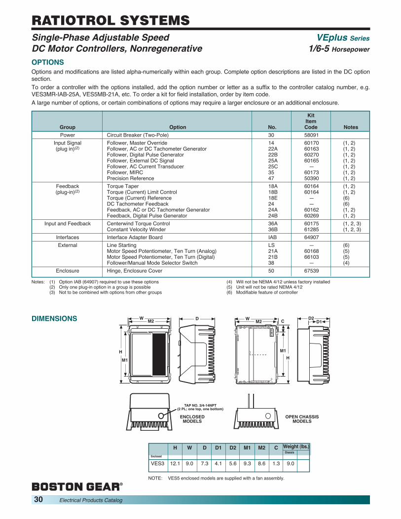
30 Electrical Products Catalog
RATIOTROL SYSTEMS
OPTIONSOptions and modifications are listed alpha-numerically within each group. Complete option descriptions are listed in the DC optionsection.To order a controller with the options installed, add the option number or letter as a suffix to the controller catalog number, e.g.VES3MR-IAB-25A, VES5MB-21A, etc. To order a kit for field installation, order by item code.A large number of options, or certain combinations of options may require a larger enclosure or an additional enclosure.
KitItem
Group Option No. Code NotesPower Circuit Breaker (Two-Pole) 30 58091
Input Signal Follower, Master Override 14 60170 (1, 2)(plug in)(2) Follower, AC or DC Tachometer Generator 22A 60163 (1, 2)
Follower, Digital Pulse Generator 22B 60270 (1, 2)Follower, External DC Signal 25A 60165 (1, 2)Follower, AC Current Transducer 25C — (1, 2)Follower, MIRC 35 60173 (1, 2)Precision Reference 47 50390 (1, 2)
Feedback Torque Taper 18A 60164 (1, 2)(plug-in)(2) Torque (Current) Limit Control 18B 60164 (1, 2)
Torque (Current) Reference 18E — (6)DC Tachometer Feedback 24 — (6)Feedback, AC or DC Tachometer Generator 24A 60162 (1, 2)Feedback, Digital Pulse Generator 24B 60269 (1, 2)
Input and Feedback Centerwind Torque Control 36A 60175 (1, 2, 3)Constant Velocity Winder 36B 61285 (1, 2, 3)
Interfaces Interface Adapter Board IAB 64907External Line Starting LS — (6)
Motor Speed Potentiometer, Ten Turn (Analog) 21A 60168 (5)Motor Speed Potentiometer, Ten Turn (Digital) 21B 66103 (5)Follower/Manual Mode Selector Switch 38 — (4)
Enclosure Hinge, Enclosure Cover 50 67539
Notes: (1) Option IAB (64907) required to use these options(2) Only one plug-in option in a group is possible(3) Not to be combined with options from other groups
(4) Will not be NEMA 4/12 unless factory installed(5) Unit will not be rated NEMA 4/12(6) Modifiable feature of controller
DIMENSIONS
ENCLOSEDMODELS
OPEN CHASSISMODELS
D2D1
WM2 C
M1
H
DWM2
H
M1
TAP NO. 3/4-14NPT(2 PL; one top, one bottom)
H W D D1 D2 M1 M2 C Weight (lbs.)Chassis
Enclosed
VES3 12.1 9.0 7.3 4.1 5.6 9.3 8.6 1.3 9.0
NOTE: VES5 enclosed models are supplied with a fan assembly.
Single-Phase Adjustable Speed VEplus SeriesDC Motor Controllers, Nonregenerative 1/6-5 Horsepower

TABLE OF CONTENTS
SPECIFICATION CHART ...............................................................................................................32
RBA/VEA–RG............................................................................................................................31-37
OPTIONS FOR DC CONTROLLERS........................................................................................38-46
APPLICATION ENGINEERING .............................................................................................113-127
Single-Phase Adjustable SpeedRegenerative DC Motor Controllers
Electrical Products Catalog 31
RATIOTROL SYSTEMS

32 Electrical Products Catalog
RATIOTROL SYSTEMS
REGENERATIVE DC MOTOR CONTROLLER SPECIFICATIONSFeatures RBA-RG/VEA-RG
AC Line Single-Phase Voltage 115 230(50/60 Hz) Three-Phase Voltage — —Range Maximum Horsepower 1 5Output Armature Voltage 90 180
Field Voltage 50/100 100/200AC Line Fuse S SProtection Circuit Breaker OEnclosure Open Chassis S S
Angle Bracket Chassis S SNEMA 1 SNEMA 4 S SNEMA 12 S S
Adjustments Acceleration (Seconds) 0.2–30Deceleration (Seconds) 0.2–30IR Compensation (%) 10Maximum Speed (%) 50–10Current Limit (%) 10–150GainPhase Shif
Horsepower/ Trim Pot AdjustmentsVoltage Resistance Wire SCalibration Plug In Jumpers S
SwitchIsolated Regulator OSpeed Standard IR FeedbackRegulation Percentage 2%
Speed Range 50:1Tachometer Feedback
Percentage 0.5%Speed Range 200:1
Input Analog SDigital
Tachometer Bidirectional SFeedbackOptions Field Installed O
Factory InstalledUL/cUL SPages 33-37
Single-Phase Adjustable Speed SpecificationRegenerative DC Motor Controllers ChartThe purpose of this chart is to provide a general feature comparison of the Boston Gear controllers. When selecting refer to thespecific catalog selection for complete information.
S-Standard O-Optional

Boston Gear RBA-RG/VEA-RG regenerative controllers, are economical, generalpurpose units. The units feature static conversion of AC line power to regulated directcurrent adjustable speed, four-quadrant armature control of shunt-wound orpermanent magnet DC motors. The compact dimensions and design features of theunits make this series of controllers an ideal choice for numerous industrialapplications which require controllable bidirectional speed and torque for overhaulingloads, contactorless reversing and static braking.RBA-RG & VEA-RG units are identical in standard features and functions and differonly in mechanical configuration and horsepower range. RBA-RG Series units aresmaller, are limited to three horsepower maximum and will accept a limited number ofoptions. VEA-RG Series units are physically larger permitting ratings through fivehorsepower and provide greater available space to facilitate mounting a wide range ofoptional features. Accordingly, RBA-RG Series units are preferred in space intensiveapplications where the standard features and functions are adequate for theapplication. The RBA-RG Series is available as standard in open and enclosedconfigurations along with the angle bracket chassis style. The VEA-RG Series isavailable as standard in the open and enclosed configuration.RBA-RG/VEA-RG controllers are designed and manufactured to comply withapplicable standards established by the National Electrical Code and NEMA forindustrial motor and control equipment. The units are UL and cUL Listed.
Single-Phase Adjustable Speed RBA-RG/VEA-RG SeriesRegenerative DC Motor Controllers 1/6-5 Horsepower
1. Construction – The die-cast aluminum alloy base assemblyforms the basic RBA-RG Series open chassis (excludingRBA2C-RG units) which includes regulator electronics, AC linefuse, power conversion and protective circuitry as a totallyfunctional, self-contained unit. The entire back surface of theVEA-RG Series base is a unique, pin configuration heatsink withomni-directional heat dissipation characteristics. This allowsvertical or horizontal wall mounting as best suits the availablespace. All open models are cooled by natural convection.Conduit entry is provided in the base by two 3/4-14 NPT tappedholes, one each on the top and bottom.Enclosed models consist of the basic chassis with the addition ofa screw fixed cover which is gasketed with an oil resistantsynthetic rubber gasket to exclude contaminants. Basic enclosedunits are TENV, NEMA 4 and 12. All models with integraloperator controls also include flexible boots to seal the operatorcontrol switches and a seal for the motor speed potentiometer.RBA3-RG Models, when rated three (3) horsepower as anenclosed unit, requires the use of a stand off kit (Option SK).This is included when an enclosed controller is ordered.VEA5-RG Models, when rated five (5) horsepower as anenclosed unit, requires the addition of Option VFKT cooling fanassembly. This is included when an enclosed controller isordered.VEA-RG Series unit covers are molded of high strength Noryl®engineering plastic. An aperture in the cover permits mounting ablank panel for remote control models or various standard oroptional local operator control panels. Where a hinged cover isdesired, Option 50 provides a kit permitting easy fieldinstallation.RBA-RG Series unit covers are die-cast aluminum alloy. Variouscover models are provided. Blank face models include nooperator control elements, as they are intended for remotecontrol operation. The local control model provides a motorspeed potentiometer and Run/Stop Jog toggle switch.
RBA2C-RG Models are offered only in a special space savingchassis configuration, formed of aluminum into a Right Anglechassis design, which requires only two (2) mounting screws.
2. Full-Wave Power Conversion – Dual full-wave converterconfiguration, consists of eight (8) SCRs connected in back toback bridges of four (4) SCRs each. The SCR’s are rated 600PIV minimum.
3. Voltage Transient Protection – Metal oxide suppressor withRC snubbers across the AC line input and a second RCsnubber across the DC output.
4. AC Line Protection – A 100,000 ampere interrupting capacityAC line fuse provides instantaneous protection from peakloads and fault currents. This line fuse is located inside thecontroller. A molded-case magnetic-trip circuit breaker (Option30) is available for VEA-RG Model controllers, which providesa manual disconnection to the controller, and also providesautomatic instantaneous trip protection from a peak load.
5. AC Line Power – Controllers are reconnectable for 115 or230 VAC, single-phase, 50 or 60 Hertz.
6. Safety Features – UL listed and cUL. Requires mandatoryrestart after power interruption.
7. AC Line Starting – Provision is included to defeat themandatory restart after power interruption to permit run-stopcontrol of the units by an external AC line contactor.
8. Deadband Selection – This will help to eliminate “creeping”motor speed with zero speed reference signal. It gives a non-adjustable ±2% deadband around zero speed.
9. Field Supply – Transient protected, full-wave and half-wavefield supply.
10. Operator Controls – Units with a “S” suffix in the catalognumber (example: RBA2S-RG) contain a motor speedpotentiometer and a Run-Stop-Jog switch. The speedpotentiometer is reconnectable for unidirectional orbidirectional operation.
DESIGN FEATURES AND FUNCTIONS
Electrical Products Catalog 33
RATIOTROL SYSTEMS

34 Electrical Products Catalog
RATIOTROL SYSTEMS
11. Static Reversing – Solid state, electronic reversal of the motorarmature. No reversing contacts to burn, arc or wear.
12. Static Braking – Provides smooth regeneration braking of theDC drive motor. Braking is effective whenever the manual speedcontrol potentiometer is reset to command a reduction in speedor change in the direction of motor rotation.
13. DC Tachometer Feedback – Unit includes terminals to accept a 5.5to 100VDC/1000 RPM (1750 RPM maximum) signal from a motormounted DC tachometer generator for improved speed regulation.
14. External Current (Torque) Control – Terminals are provided forexternal forward and reverse current limit (torque) control.
15. Diagnostic LED – A dual color LED, green for power on, red forcurrent limit is provided.
16. Customer Use Run Contacts – Form A normally open contactrated five (5) amps at 115 VAC or 30 VDC coordinated with runcommand may be used for external control and indicating devices.May be applied as pushbutton seal-in or a drive “RUN” contact.
17. Hybrid Circuitry – Miniature components in a custom surfacemount assembly, improve reliability and make possible morefeatures in the smallest possible mechanical configuration.
18. Option Connectors – These connectors are provided for optionsthat fit in a space provided inside the controller.
19. Dynamic Braking – Standard feature of model numbers with a“U” suffix. Dynamic braking provides exponential rate braking ofthe DC motor armature. Included is a Dynamic Braking resistorwith an anti-plug circuit to prevent restarting the controller untilthe braking cycle is complete, thereby preventing a potentiallydamaging contact arcing. The Dynamic Braking resistor is ratedfor stopping a typical load, when the external machine inertiadoes not exceed that of the motor armature, as shown in table.
20. Control Voltage – A transformer coupled 24 VDC power supplyprovides non-isolated control power for all magnetic control logicand operator controls.
21. DIP Switch Settings – An 8-position DIP Switch is used toprogram the controller for various applications and operations.
22. Motor Contactor – Controller model numbers with a “U” suffix,e.g., RBA2U-RG, VEA5US-RG, have a DC magnetic armaturecontactor, which disconnects both motor armature leads from thecontroller. An antiplug circuit ensures that the contactor does notmake or break DC from the SCR bridge.
MOTOR ROTATION
TORQUE
NOTE:
QUADRANT I
QUADRANT III
QUADRANT II
QUADRANT IVARROWS
SAME DIRECTIONMOTORING (PULLING)
ARROWSOPPOSITE DIRECTIONBRAKING (HOLDING)
Control MagneticPower Source Output VDC Reference Control(Single-Phase) Armature Field Voltage Voltage
115V, 50 or 60 Hz 0-90 50/1000 to ±10 VDC 24 VDC
230V, 50 or 60 Hz 0-180 100/200
OPERATING VOLTAGES
PRINCIPLES OF OPERATIONRegenerative adjustable speed drives, also known as four-quadrantdrives, are capable of controlling not only the speed and direction ofmotor rotation, but also the direction of motor torque. This isillustrated to the right.The term regenerative describes the ability of the drive underbraking conditions to convert the mechanical energy of the motorand connected load into electrical energy which is returned (orregenerated) to the AC power source.When the drive is operating in Quadrants I and III, both motorrotation and torque are in the same direction and it functions as aconventional nonregenerative unit. The unique characteristics of aregenerative drive are apparent in Quadrants II and IV. In thesequadrants the motor torque opposes the direction of motor rotationwhich provides a controlled braking or retarding force. A highperformance regenerative drive, such as the RBA-RG/VEA-RGSeries, is able to switch rapidly from motoring to braking modeswhile simultaneously controlling the direction of motor rotation.
RATINGS1. Horsepower Range . . . . . . . . . . . . . . . . . 1/6-5 HP2. Power Source . . . . . . . . . . . . . . . 115 or 230 VAC,
. . . . . . . . . . . . . . . . . . . Single-Phase, 50 or 60 Hz3. Operating Voltages
4. Service Factor . . . . . . . . . . . . . . . . . . . . . . . . . 1.05. Duty . . . . . . . . . . . . . . . . . . . . . . . . . . . Continuous6. Overload Capacity(Armature Circuit) . . . . . . . . . . 150% for 1 Minute
7. Line Fuse Interrupting Capacity(Non-Isolated). . . . . . . . . . . . . . . . . 100,000 Amps
8. Reference Power Supply(Non-Isolated) . . . . . . . . . . . . . . . . . . . . . ±10VDC
9. Run Speed Potentiometer . . . . 10K ohms, 1/2 W10. Current/Torque Reference
Potentiometer . . . . . . . . . . . . . . 10K ohms, 1/2 W
DYNAMIC BRAKING CHARACTERISTICS (1) (2)
Rated Rated HorsepowerComponent Model Voltage 1/6 1/4 1/3 1/2 3/4 1 11⁄2 2 3 5
RBA2-RG 115V 180 129 103 66 44 34 N/A N/A N/A N/A230V N/A N/A 400 278 200 138 93 66 N/A N/A
BrakingRBA3-RG
115V 300 214 171 111 74 57 N/A N/A N/A N/ATorque (%) 230V N/A N/A N/A 462 316 218 146 103 79 N/A
VEA5-RG115V 600 429 343 222 148 114 N/A N/A N/A N/A
230V N/A N/A N/A 923 632 436 293 207 159 96RBA2-RG 115V 15 12 11 8 6 2 N/A N/A N/A N/A230V N/A N/A 12 8 6 2 1 1 N/A N/A
Stops PerRBA3-RG
115V 9 6 5 5 4 4 N/A N/A N/A N/AMinute 230V N/A N/A N/A 5 4 4 3 3 2 N/A
VEA5-RG115V 15 12 10 10 7 7 N/A N/A N/A N/A
230V N/A N/A N/A 10 7 7 5 5 3 2
Single-Phase Adjustable Speed RBA-RG/VEA-RG SeriesRegenerative DC Motor Controllers 1/6-5 Horsepower
Notes: (1) Ratings shown for units with contactor board (Model number contains “U”suffix, ex RBA3U-RG).(2) High inertia loads may extend braking time and cause the wattage rating
of the dynamic braking resistors to be exceeded.
DESIGN FEATURES AND FUNCTIONS (Continued)

Component RatingsRated Horsepower (HP) 1/6 1/4 1/3 1/2 3/4 1 1-1/2 2 3 5Rated Kilowatts (kW) 0.124 0.187 0.249 0.373 0.560 0.746 1.120 1.492 2.238 3.730
115V 3.9 5.0 6.0 8.7 12.4 15.8 — — — —1-Phase Line UnitAC Input Amps 230V — — — 4.2 5.9 8.8 12.6 15.8 22.0 32.0(Full-Load) Unit
KVA 0.48 0.58 0.71 1.00 1.40 2.00 3.00 4.00 5.00 8.00Motor 90V 2.0 2.8 3.5 5.4 8.1 10.5 — — — —
ArmatureDC Output Amps 180V — — — 2.6 3.8 5.5 8.2 11.6 15.1 25.0(Full-Load) Motor RBA-RG 1.0 1.0 1.0 1.0 1.0 1.0 1.0 1.0 1.0 —
FieldAmps VEA-RG 2.0 2.0 2.0 2.0 2.0 2.0 2.0 2.0 2.0 2.0
Full Load Torque (lb-ft)with 1750 RPM Base Speed Motors 0.5 0.75 1.0 1.5 2.2 3.0 4.5 6.0 9.0 15.0
Minimum Transformer KVA for 0.5 0.75 0.75 1.0 1.5 2.0 3.0 5.0 7.5 10.0Voltage Matching or Isolation
TYPICAL APPLICATION DATA
ADJUSTMENTSPotentiometer adjustments are provided for:1. Current Limit...........................10-150% Full-Load Torque(Independent forward and reverse circuits)2. Maximum Speed ..............50-100% of Motor Base Speed3. IR (Load) Compensation .................................10% Boost4. Acceleration .........................................0.2 to 30 Seconds5. Deceleration .........................................0.2 to 30 Seconds6. Deadband (Yes or No Adjustment) ...................0 or ±2%7. Jog Speed.......................0 to 100% of Motor Base Speed
OPERATING CONDITIONS1. Line Voltage Variation ...............................±10% of rated2. Line Frequency Variation........................................±2 Hz3. Ambient Temperature (1) ...............................0°C to 40°C
(32°F to 104°F)4. Altitude (Standard)........................................1000 meters(3300 feet) Maximum5. Relative Humidity.............................95% Noncondensing
(1) 0°C to 55°C (32°F to 131°F) maximum in enclosed areas where chassismodels are mounted.
PERFORMANCE CHARACTERISTICS1. Controlled Speed Range – Zero to motor base speed.
Speed range with respect to specified regulation is listedin Table. See page I2 for continuous duty applicationlimitations of DC motors.
2. Speed Regulation – Regulation percentages shown inTable below are of motor base speed under steady-stateconditions.
3. Efficiency (Rated speed/Rated load)(a) Controller SCR regulator .......................................98%(b) Complete drive with motor (typical) .......................85%5. Current Ripple Frequency .................120 Hz (60 Hz line)
100 Hz (50 Hz line)4. Controller Bandwidth (Speed of Response) ...........5 Hz
Variable
Regulation Field SpeedMethod
Load Line Heating Temp. RangeChange Voltage Cold/ ±10°C95% ±10% NormalStandard VoltageFeedback with IR 2% ±1% 5-12% ±2% 50:1Compensation
TachometerFeedback with5 PY DC Tach 0.5% ±1% 0.2% ±2% 200:1Feedback
SPEED REGULATION CHARACTERISTICS
Single-Phase Adjustable Speed RBA-RG/VEA-RG SeriesRegenerative DC Motor Controllers 1/6-5 Horsepower
Electrical Products Catalog 35
RATIOTROL SYSTEMS
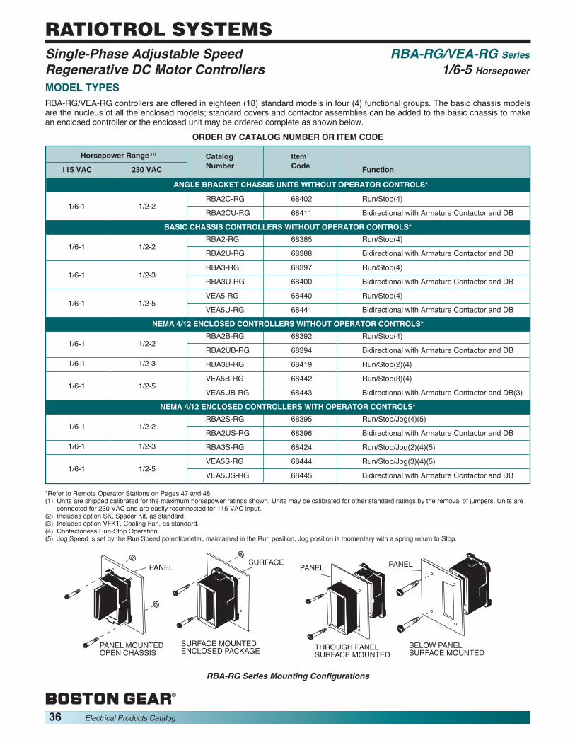
36 Electrical Products Catalog
RATIOTROL SYSTEMS
PANEL PANELPANELSURFACE
PANEL MOUNTEDOPEN CHASSIS
SURFACE MOUNTEDENCLOSED PACKAGE THROUGH PANEL
SURFACE MOUNTEDBELOW PANELSURFACE MOUNTED
RBA-RG Series Mounting Configurations
MODEL TYPESRBA-RG/VEA-RG controllers are offered in eighteen (18) standard models in four (4) functional groups. The basic chassis modelsare the nucleus of all the enclosed models; standard covers and contactor assemblies can be added to the basic chassis to makean enclosed controller or the enclosed unit may be ordered complete as shown below.
ORDER BY CATALOG NUMBER OR ITEM CODE
Horsepower Range (1) Catalog Item115 VAC 230 VAC Number Code Function
ANGLE BRACKET CHASSIS UNITS WITHOUT OPERATOR CONTROLS*
1/6-1 1/2-2RBA2C-RG 68402 Run/Stop(4)
RBA2CU-RG 68411 Bidirectional with Armature Contactor and DB
BASIC CHASSIS CONTROLLERS WITHOUT OPERATOR CONTROLS*
1/6-1 1/2-2RBA2-RG 68385 Run/Stop(4)
RBA2U-RG 68388 Bidirectional with Armature Contactor and DB
1/6-1 1/2-3RBA3-RG 68397 Run/Stop(4)
RBA3U-RG 68400 Bidirectional with Armature Contactor and DB
1/6-1 1/2-5VEA5-RG 68440 Run/Stop(4)
VEA5U-RG 68441 Bidirectional with Armature Contactor and DB
NEMA 4/12 ENCLOSED CONTROLLERS WITHOUT OPERATOR CONTROLS*
1/6-1 1/2-2RBA2B-RG 68392 Run/Stop(4)
RBA2UB-RG 68394 Bidirectional with Armature Contactor and DB1/6-1 1/2-3 RBA3B-RG 68419 Run/Stop(2)(4)
1/6-1 1/2-5VEA5B-RG 68442 Run/Stop(3)(4)
VEA5UB-RG 68443 Bidirectional with Armature Contactor and DB(3)
NEMA 4/12 ENCLOSED CONTROLLERS WITH OPERATOR CONTROLS*
1/6-1 1/2-2RBA2S-RG 68395 Run/Stop/Jog(4)(5)
RBA2US-RG 68396 Bidirectional with Armature Contactor and DB1/6-1 1/2-3 RBA3S-RG 68424 Run/Stop/Jog(2)(4)(5)
1/6-1 1/2-5VEA5S-RG 68444 Run/Stop/Jog(3)(4)(5)
VEA5US-RG 68445 Bidirectional with Armature Contactor and DB
*Refer to Remote Operator Stations on Pages 47 and 48(1) Units are shipped calibrated for the maximum horsepower ratings shown. Units may be calibrated for other standard ratings by the removal of jumpers. Units are
connected for 230 VAC and are easily reconnected for 115 VAC input.(2) Includes option SK, Spacer Kit, as standard.(3) Includes option VFKT, Cooling Fan, as standard.(4) Contactorless Run-Stop Operation.(5) Jog Speed is set by the Run Speed potentiometer, maintained in the Run position, Jog position is momentary with a spring return to Stop.
Single-Phase Adjustable Speed RBA-RG/VEA-RG SeriesRegenerative DC Motor Controllers 1/6-5 Horsepower

9.12
9.5
4.005.00
.505.25
.19
TAP NO. 3/4-14 NPSC(2 PL)
9.12
9.5
4.00
5.00
.504.30
2.25
8.00
TAP NO. 3/4-14 NPSC(2 PL))
.19
4.25 1.75 3.312
8.00
8.88
DIMENSIONS
RBA2C-RG RBA-RG
VEA-RG
Allowable Option Combinations
ENCLOSEDMODELS
OPEN CHASSISMODELS
6.54.1
9.08.6 1.3
12.1
9.3
9.09.08.6
12.1
9.3
OPTIONSThe versatility of the RBA-RG/VEA-RG Series controllers for various applications can be extended by selecting one (1) or more ofthe listed options. Most can be easily added in the field via simplified instructions provided. The table below lists the options infunctional groups along with information on allowable combinations and installation complexity.
Catalog KitRemarks Option Number Number Notes
Enclosure Options—Choice of any or all Hinge kit to allow the cover to swing open 50 67539within this group. May be combined with Spacer kit for RBA3B-RG, RBA3S-RG enclosed controllers SK 68416options from any other group.Power Options Circuit Breaker—Two Pole (VEA-RG only) 30 68456Accel/Decel Option Four-Quadrant Acceleration/Deceleration 17 68457Circuit Board Options— Torque Taper 18 68458 (1)Choice of one within this group Pulse Tachometer Feedback/Follower 24B 68462 (1)
Isolated Input 25 68478Limit Switch Reversing RI 68461 (1)
External Options— Motor Speed Potentiometer, One-Turn 21 — (2)Choice of any or all within this group Motor Speed Potentiometer, Ten-Turn With Analog Dial 21A 66929 (2)
Option Guide Card Kit MK 68476 (1)Option/Contactor Mounting Kit for RBA2C-RG SKO 64101
CONTROLLER WEIGHTSUnit Weight lbs.RABA2-RG, RBA3-RG 7.70RBA2U-RG, RBA3U-RG 8.50RBA2B-RG, RBA3B-RG 11.60RBA2S-RG, RBA3S-RGRBA2UB-RG 12.40RBA2US-RGRBA2C-RG 2.00RBA2CU-RG 2.25VEA5-RG 8.20VEA5U-RG 8.90VEA5B-RGVEA5S-RG 12.50
VEA5UB-RGVEA5US-RG 13.20
(1) Option MK is a pre-requisite to enable the use of options in the VEA-RG Series.(2) Will not be NEMA 4/12 unless factory installed.
ENCLOSED OPEN CHASSISMODELS MODELS
Single-Phase Adjustable Speed RBA-RG/VEA-RG SeriesRegenerative DC Motor Controllers 1/6-5 Horsepower
Electrical Products Catalog 37
RATIOTROL SYSTEMS

38 Electrical Products Catalog
RATIOTROL SYSTEMSOptions and Modifications for DC Controllers
For UseOption withNo. Description SeriesCL MAGNETIC CONTROL INTERFACE (115V) VEplus
The standard magnetic control run logic excitation is 24 VDC, obtained from a self-contained power supply in theVEplus controllers. This option provides a means of interfacing a controller with pushbuttons or external logic poweredby a 115 or 230 VAC excitation source. The interface circuit includes three control relays with 115 VAC coils for use inboth unidirectional and reversing applications.
IAB INTERFACE, SIGNAL OPTIONSSeries VEplus units incorporate as standard many of the functions that were formerly offered as extra cost options onthe products they replace. However, some special applications may still require the use of signal options. Option IABenables the use of these options by providing a power supply, mounting area and an electrical connector to interfaceand mate with these options. This option mounts within the VEplus chassis.
Space limitations prevent mounting this option within the BETA units and therefore it may be mounted externally withbrackets provided in a kit.
LS LINE STARTING BETA llA modification which will defeat the internal “anti-restart” feature of the controller. An external AC line contactor BETAplusmay then be used to start and stop controller VEplus
MK OPTION CARD GUIDE KIT VEA-RGThis option is required when mounting the option cards in the enclosure or if the option cards are mounted external.
RI LIMIT SWITCH REVERSINGThis option board allows interfacing the controller with a variety of external devices, such as limit switches, pushbuttons and potentiometers. There are two (2) speed potentiometers on this board, one (1) for forward speed and one(1) for reverse speed. These internal potentiometers can be switched out if external potentiometers are required. Inaddition, this board will allow a controlled stop feature with an adjustable speed dropout.
SK SPACER KIT FOR 3 HP RBA-RG ENCLOSED CONTROLLER RBA-RGThis spacer kit is required for mounting controllers when they are to be used for their maximum 3 HP rating.
SKO OPTION MOUNTING KIT RBA-RGThis kit contains standoffs for mounting an optional contactor or option board onto an Angle Bracket chassis.
14 MASTER OVERRIDE (FOLLOWER, EXTERNAL AC SIGNAL) VEplusProvides necessary impedance matching, isolation, signal conversion and filtering as required to adjust the speed of thedrive (or drives) from an external AC signal source. Option 14 permits full range speed control from an external 0 to 115 VACadjustable signal source manually controlled by a potentiometer, variable autotransformer or some other suitable means.This option is required for each controller which is to be controlled by the external AC signal.Included in this option are minimum and maximum speed adjustments, with the normal drive run speed potentiometerfunctioning as a ratio setting when following the external AC signal. This option is useful for multiple section machineswhere a definite speed relationship must be maintained between sections, while the entire machine is varied over aspecified speed range by a common manual speed control device.This option consists of a small plug-in circuit board which inserts into the input connector of the control board.The option does not include the external AC signal source.Master Override Station Cat. No. 62317 provides the required master signal and also includes master run-stop pushbuttons. (Option 14A)If the controls are to be started with individual pushbutton stations, Master Station Cat. No. 62311 may be used toprovide master speed control only. (Option 14B)
17 FOUR-QUADRANT ACCELERATION/DECELERATION VEA-RGThis option board has four (4) adjustment potentiometers consisting of a forward acceleration potentiometer, aforward deceleration potentiometer, a reverse acceleration potentiometer and a reverse deceleration potentiometer.The potentiometers have an adjustment range of .3 to 30 seconds. Also, the board has a bypass mode to disable thefour (4) potentiometers on the option board and switch to the two (2) potentiometers (acceleration and deceleration)on the control board.This option board mounts on the control board and does not take up the option slot in the casting base.
BETA IIBETAplusVEplus
VEA-RGRBA-RG
RBA-RG

For UseOption withNo. Description Series18 TORQUE TAPER VEA-RG
This option consists of a plug-in circuit board. This board provides an inverse-linear speed-torque relationship whenoperating in the braking (regenerative) mode, and provides constant torque in the motoring mode of operation.Motoring torque and braking torque are individually adjustable as well as forward and reverse torque taper.Applications include the following:1. Winders where the material being wound travels at a constant speed during winder roll buildup.2. Unwinders, since this option provides relatively constant holdback tension (±20%) from full roll to empty roll.
18A TORQUE TAPER VEplusCenter driven winders ideally require a reciprocal speed torque relationship (constant horsepower) to maintainconstant tension throughout the range of material build-up. Acceptable performance can be economically achieved formany applications with an inverse-linear speed-torque relationship provided by this option. Tension control accuracy ofapproximately 20% can normally be maintained from empty to full roll at a given machine speed.This option consists of a plug-in circuit board which replaces the FEEDBACK board in the control and a torquepotentiometer for installation in the operator’s panel. Independent potentiometers are provided for:TORQUE ADJUST—Establishes maximum low speed torque. The TORQUE ADJUST in combination with the SLOPEADJUST establishes the torque available at any point throughout the operating speed rangeSLOPE ADJUST–Establishes the rate of torque increase with decreasing speed, throughout the operating range.Adjustable from 0 to 100% torque at maximum motor speed with minimum effect on low speed torque. The SLOPEADJUST potentiometer is mounted within the controller on the option circuit board.Use caution in the selection of motors for center driven windup applications where torque loads increase ininverse proportion to motor speed. Web break or other process material detectors are recommended toprevent a dangerous overspeed should the process material break.Option 18A normally provides acceptable performance in applications where the material being wound travels at aconstant speed during winder roll buildup. If the process is such that the speed of the material being wound variesduring winder roll buildup or if more accurate tension control is desired, see Option 36A.This Option Kit is also used for constant torque applications where conventional operation of the current limit isrequired and remote mounting of the torque (current) potentiometer is desired. When used in this manner, the Slopeadjustment is set for a vertical cutoff of motor (maximum setting) torque (current). See Option 18B.
18B TORQUE (CURRENT) LIMIT CONTROL VEplusProvides the ability to adjust the drive current limit setting and thus the motor torque over a range of 50-150% by aremote mounted TORQUE ADJUST potentiometer. (See Option 18A).
18C FOLLOWER, CURRENT REGULATOR VEplusProvides a means of controlling motor armature current and torque by a manually adjusted potentiometer or anexternal DC voltage reference signal. The circuit includes internal isolation permitting direct connection to a groundedsignal source. Since torque is directly controlled independent of motor speed, provision is included for limitingmaximum motor speed.
Multiple motor applications typically involve master speed regulated drive which establishes the speed of the systemand one (1) or more current regulated follower drive units. The follower units obtain their current reference signal fromthe master controller. Typical applications include:
a. Load sharing between two (2) or more drive units with their motors mechanically coupled.b. Load sharing between two (2) or more drive units coupled by the process material itself such as steel bar stockbeing pulled by multiple drive units through separately powered sections of a machine.
18C FOLLOWER, CURRENT REGULATOR (LESS ADJUSTMENTS) (Continued)
EP138BR
PM
MOTOR TORQUE50% (MIN) 150% (MAX)
MOTOR TORQUE
RPM
50% 100%MOTOR TORQUE
WIN
DER
RPM
FIGURE A.“Ideal” Constant HPcurve for a winder
application
FIGURE B.Torque Adjust with slopeadjust at maximum
FIGURE C.Slope Adjust withtorque adjust at
100% torque setting
RBA-RG
Electrical Products Catalog 39
RATIOTROL SYSTEMSOptions and Modifications for DC Controllers

40 Electrical Products Catalog
RATIOTROL SYSTEMSOptions and Modifications for DC Controllers
For UseOption withNo. Description Series
c. Tension control of a web of process material being transferred between sections of a multiple section machine.
APPLICATION INFORMATION1. Current response timeZero to full-load current ............................................................................................................................150 Milliseconds2. Output current controlRange ..........................................................................................................................................................................10:13. Signal input required for maximum current outputRange 1...................................................................................................................................................3.35 to 36.5 VDCRange 2.....................................................................................................................................................0.34 to 3.7 VDCRange 3...................................................................................................................................................0.04 to 0.44 VDC4. Transfer linearityInput signal to output current .........................................................................................................................................1%This option consists of a plug-in circuit board which inserts into both input and feedback connectors of the controlboard. Included are separate adjustments for:Maximum Speed ..........................................................................................................................0-Motor Base SpeedMaximum Current ............................................................................................................................0-150% of rated(1)Input Scaling ..........................Adjustable to match the input signal (0.04 to 36.5 VDC) for maximum current output.Current offset ...............................................................Adjustable for zero current output with minimum signal input.
(1) 0-75% of rated achieved by adjustment of the unit current limit.
18E TORQUE (CURRENT) REFERENCE BETA IIA modification that will allow the controller to function as a torque regulator. This modification allows the use of anexternal potentiometer to set maximum motor torque (0-150% of rated).
21 POTENTIOMETER, SINGLE TURN MOTOR SPEED ALLProvides a single turn, 2W potentiometer, knob and analog dial plate.Not intended for bidirectional operation via speed potentiometer.
21A POTENTIOMETER, TEN-TURN MOTOR SPEED (ANALOG) ALLProvides a Ten-Turn, 2W potentiometer, knob and analog dial.Not intended for bi-directional operation via speed potentiometer.
21B POTENTIOMETER, TEN-TURN MOTOR SPEED (DIGITAL) ALLProvides a Ten Turn, 1/2W Potentiometer with digital dial and knob.Not intended for bi-directional operation via speed potentiometer.
22A FOLLOWER, AC OR DC TACHOMETER GENERATOR VEplusIntended for automatic control systems where it is necessary for the drive to follow the speed of a preceding drive unit orrotating machine coupled to an AC or DC tachometer generator. The tachometer voltage signal provides the speedreference for the “follower” drive.Option 22A is not recommended for use where multiple drive controllers are required to operate from a common signalsource, unless the controllers are isolated. A more economical approach if the controllers are not isolated would be the useof the MIRC master isolated reference controller which is intended for use with multiple drive controllers. See Option 35.Adjustments are provided to adapt the unit to a wide range of system requirements. Included are independentadjustments for:TACH SCALING – Adjustable to interface the tachometer generated voltage with the required controller reference voltagewhen the FOLLOWER RATIO potentiometer is set on maximum. If a plus ratio is required (i.e.: the follower drive is at fullspeed when the master drive is at half speed) set the FOLLOWER RATIO potentiometer at its midpoint and adjust TACHSCALING for the required controller reference voltage and then adjust the FOLLOWER RATIO potentiometer toward 100.FOLLOWER RATIO – Adjustable to permit tracking the tachometer signal voltage at a plus or minus ratio.The FOLLOWER RATIO potentiometer is mounted in the operator control panel.MINIMUM SPEED (Additive)–Adjustable to permit tracking the tachometer signal at a fixed offset voltage.MINIMUM SPEED ADDITIVE potentiometer is mounted on the Option 22A circuit board.
VEplus
BETAplusVEplus

For UseOption withNo. Description Series
22A FOLLOWER, AC OR DC TACHOMETER GENERATOR (Continued)MINIMUM SPEED (Override)–Adjustable by the MOTOR SPEED potentiometer to establish a minimum drive speedindependent of tachometer signal voltage. The MOTOR SPEED potentiometer is also used as a manual speed settingcontrol when no tachometer signal is present. The MOTOR SPEED potentiometer is mounted in the operator controlstation.A MANUAL/FOLLOWER selector switch is therefore unnecessary for most applications and is not included with this option.See Option 38 when a switch is desired. The MOTOR SPEED potentiometer is mounted in the operator control station.Option 22A consists of a small plug-in circuit board which inserts into the input connector of the Control Circuit Boardand a FOLLOWER RATIO potentiometer for separate mounting.This option does not include the tachometer generator which must provide 30 volts at base speed and not to exceed180 volts at maximum speed.
22B FOLLOWER, DIGITAL PULSE GENERATOR VEplusThis option provides signal conditioning and isolation for accepting a signal from a magnetic pulse pick-upmechanically coupled to a preceding drive motor, rotating machinery or various static pulse generators permitting thedrive to follow at an adjustable ratio.This option consists of:a. Digital to analog conversion circuit board which inserts into the INPUT connector of the control circuit board.b. A signal conditioning circuit board which is mounted in the base of the controller or remotely mounted.c. MANUAL/FOLLOWER selector switch for separate mounting.d. Interconnection wire harness.Two (2) modes of operation are provided: Manual and Follower, as selected by the MANUAL/FOLLOWER switch. Inthe Manual mode, the MOTOR SPEED potentiometer controls motor speed. In the Follower mode, the motor followsthe digital pulse signal, and the MOTOR SPEED potentiometer functions as the follower ratio adjust potentiometer.The signal conditioner circuit board accepts the output of any one of the following devices:1. Magnetic pulse pick-up capable of providing 450 pulses/second at motor base speed and not exceeding a
maximum of 2500 pulses/second at motor base speed. Recommended input:100 tooth gear on a 1150 RPM motor.60 tooth gear on a 1750 RPM motor.30 tooth gear on a 2400 RPM motor.
2. Pulse generator (TTL) with a 0 to +5V output, capable of providing a minimum of 450 pulses/second at motor base speed and not exceeding a maximum of 2500 pulses/second at motor base speed.
3. Pulse generator with an open collector output, capable of conducting 2 milliamperes at 24 VDC.This option does not include the magnetic pick-up assembly, pulse gear or other signal source, or the motor speedpotentiometer.
24 TACHOMETER FEEDBACK BETA IIAn internal modification which provides impedance matching from a DC tachometer generator which is directly coupled to
the motor armature. This option improves speed regulation with respect to changes in load, line voltage, ambienttemperature and motor field heating. The tachometer generator must be capable of providing 5 to 120 VDC/1000 RPM.The tachometer generator is not part of this option.
24A FEEDBACK, TACHOMETER AC OR DC VEplusProvides impedance matching and terminals for accepting a signal from a 2-phase AC or DC tachometer generator,mechanically coupled to the drive motor armature. The tachometer signal defeats the IR compensation circuitry in the
VEplus
MOTOR
SPEED
TACH VOLTAGE TACH VOLTAGE
MOTOR
SPEED
TACH VOLTAGE
MOTOR
SPEED
MOTOR
SPEED
TACH VOLTAGE TACH VOLTAGE
MOTOR
SPEED
TACH VOLTAGE
MOTOR
SPEED
FIGURE A. TACHSCALING AND
FOLLOWER RATIO
FIGURE B. MINIMUMSPEED ADDITIVE
FIGURE C. MINIMUMSPEED OVERRIDE
BETAplusVEplus
Electrical Products Catalog 41
RATIOTROL SYSTEMSOptions and Modifications for DC Controllers

42 Electrical Products Catalog
RATIOTROL SYSTEMSOptions and Modifications for DC Controllers
For UseOption withNo. Description Series
24A FEEDBACK, TACHOMETER AC OR DC (Continued)drive controller making the unit directly sensitive to motor speed. This results in expanded speed range, improved speedregulation with load changes and reduced sensitivity to operating conditions such as line voltage variations, ambienttemperature changes, motor field heating and other operating variables. The controller will automatically switch to
armature feedback if the tachometer signal is lost.Tachometer generator must provide 30 to 180 volts at maximum motor speed. A MAXIMUM SPEED TACHOMETERpotentiometer is provided to scale the tachometer signal.Option 24A consists of a small plug-in circuit board which inserts into the FEEDBACK connector on the control circuitboard, replacing the armature feedback circuit board. Option 24A does not include the tachometer generator.Caution: Do not use a single-phase AC Tachometer.
24B FEEDBACK, DIGITAL PULSE GENERATOR VEplusProvides signal conditioning and isolation for accepting a signal from a magnetic pulse pick-up mechanically coupled tothe drive motor armature. The magnetic pulse pickup must provide a minimum of 450 pulses per second at motorspeed (60 tooth gear on a 1750 RPM motor). The pulse pick-up signal defeats the IR compensation circuitry in the drivecontroller, making the unit directly sensitive to motor speed. Speed range is limited to 35:1.The option results in improved speed regulation with load changes (equal to DC tachometer feedback) and reducedsensitivity to operating conditions such as line voltage variations, ambient temperature changes, motor field heating andother variables.Option 24B consists of:a. Digital to analog conversion circuit board which inserts into the FEEDBACK connector of the control circuit board.b. A signal conditioner circuit board which is mounted on the base of the controller or remotely mounted.This option does not include the pulse pick-up assembly.
24B PULSE TACHOMETER FEEDBACK/FOLLOWER VEA-RGThis option is interfaces the controller to a pulse train for speed reference or as a feedback signal. It allows the use ofa 60 tooth gear for either speed reference or feedback. It is capable of providing digital pulse tach reference an/orfeedback functions. The sensor can be a magnetic pickup (2 wire), proximity sensor (3 wire), AC tachometergenerator (18 cycles/revolution), two-phase AC tachometer generator, or digital tachometer generator or encoder (240pulses/revolution) Note: two-phase AC tachometer generator can be used for follower or feedback applications, butnot both.
25 ISOLATED INPUT AND FOLLOWER VEA-RGThis option board isolates the motor speed potentiometer from the non-isolated controller for operator and equipmentsafely. Also, it will allow the controller to follow a 4-20 DCMA current signal and a wide range of DC voltage signals(±.05 to ±500 VDC). This makes the option ideal for following signal transducers, motor shunts, DC tachometergenerators and the armature voltage from DC motors.
25A FOLLOWER, DC PROCESS VEplusProvides necessary impedance matching circuitry to interface a customer supplied DC signal source with the drivecontroller reference input. Typical applications are those where motor speed must be controlled as a function of aprocess variable such as temperature, weight, flow, pressure, etc.In many applications, the reference signal is obtained from a process instrument controller or other commerciallyavailable transducer with a DC milliampere output. Devices of this type normally provide signal levels compatible withrequirements listed in the table:
Included are suitable adjustments for linear transfer ofinstrument output current to motor speed. The adjustmentswill normally be set so minimum transducer signal results inminimum or zero motor speed and maximum signal producesmaximum motor speed. Also provided is an adjustment toextend or compress the transducer signal output so a 5:1transducer output signal range, for example, could providea 10:1 or 20:1 drive speed range. Included are individualpotentiometer adjustments for:MINIMUM SPEED (Override) – Adjustable by the MOTORSPEED potentiometer to establish a minimum drive speedindependent of the external reference signal. TheMOTOR SPEED potentiometer is also used as a manualspeed setting control when no external reference signalis present.
VEplus
RBA-RG
RBA-RG
DC InputSignal
Range (ma) Option Input Impedance (Ohms)0-5 800-10 400-25 160-50 81-5 802-10 404-20 1610-50 8

For UseOption withNo. Description Series25A FOLLOWER, DC PROCESS (Continued)
A MANUAL/FOLLOWER selector switch is therefore unnecessary for most applications and is not included with thisoption. See Option 38 when a switch is required. The MOTOR SPEED potentiometer is mounted in the operatorcontrol station.IMPEDANCE MATCH - Provides a means of matching the impedance of the signal source and also functions asGAIN adjustment.OFFSET - Trims minimum input signal.IMPEDANCE MATCH and OFFSET potentiometers are mounted on the Option Circuit Board
Option consists of a small plug-in circuit board which inserts into the INPUT connector of the control circuit board.Option does not include the external signal source, Motor Speed potentiometer or optional Manual Followerselector switch.
25C FOLLOWER, AC CURRENT TRANSDUCER VEplusIntended for automatic control systems where it is necessary for the drive to follow an AC signal proportional to the loadcurrent of a constant speed, AC induction motor. Typical examples are conveying systems where the material feed ratehas a direct influence over the loading of the AC motor, i.e.: the carriage or conveyor feeding logs to a saw powered byan AC motor. Since the thickness and density of the wood is not uniform this option permits automatic adjustment ofconveyor speed to the highest feed rate which will not overload the saw motor.In order that a proper current transformer may be supplied it is necessary that nameplate data such ashorsepower, voltage, load current, etc. be provided from the AC motor.AUTO/MANUAL SELECTOR SWITCH (1)–Selects the operation function. When the switch is in AUTO position, thedrive functions as an AC current follower unit. When the switch is in MANUAL position the drive functions as anadjustable speed unit. When the AUTO function is selected, the separately furnished Motor Speed potentiometerprovides speed adjustment of the DC motor at a ratio from 0 to 100% of the AC input signal. When the MANUALfunction is selected, the Motor Speed potentiometer provides normal manual speed adjustment of the DC motor.DIRECT/INVERT SLIDE SWITCH (2)–Selects the operation mode. When the switch is in DIR position, the speed of theDC drive motor varies directly proportional to the load current drawn by the AC motor. When the switch is in INVTposition the speed of the DC drive motor varies inversely proportional to the AC motor load current, i.e., when the load ofthe AC motor increases causing it to draw more current, the DC motor speed decreases.BIAS (2)–Set the maximum DC motor speed for the INVERT mode of operation.CURRENT SCALING (2)–Matches the range of the AC input signal to the input signal range requirements of thecontroller.INTEGRATION RATE (2)–Sets the response rate ofthe system when the AUTO function is selected.MINIMUM SPEED (2)–Sets minimum speedindependently of the input control signal.PROPORTIONAL GAIN (2)–Sets the gain of Circuit Boardwhen the AUTO function is selected.This option consists of:a. Toroidal current transformer for separate mounting by the user for sensing AC motor load current.b. A small plug-in circuit board which inserts into the input connector of the control circuit board.c. AUTO/MANUAL selector switch for mounting remotely.
VEplus
SAWMOTORFEED DIRECTION
ADJUSTABLESPEED CONVEYORMOTOR
MOTOR
SPEED
EXTERNAL SIGNAL
MOTOR
SPEED
EXTERNAL SIGNAL
2FIGURE A FIGURE B
Electrical Products Catalog 43
RATIOTROL SYSTEMSOptions and Modifications for DC Controllers

44 Electrical Products Catalog
RATIOTROL SYSTEMSOptions and Modifications for DC Controllers
For UseOption withNo. Description Series
25C FOLLOWER, AC CURRENT TRANSDUCER (Continued)NOTES:(1) Mounted in operator control station.(2) Located on circuit board.This illustration shows an application which requires an inverse elationship between AC motor load current andthe follower drive motor speed. This option may also be programmed for a direct relationship where the followerdrive would increase in speed with increasing AC motor load current.
30 AC LINE CIRCUIT BREAKER, TWO POLE VEA-RGProvides a two-pole, magnetic only, fast trip circuit breaker as a means of manually disconnecting controller from the ACline. The high interrupting capacity fuse in the basic unit is retained as primary short circuit protection.
34 MASTER ISOLATED REFERENCE CONTROLLERThis is a master system housed in a VEL/H size cabinet including a circuit breaker for use as an on-off switch, a run-stop control relay, operator’s controls consisting of run and stop pushbuttons and a master speed pot. Input voltagemay be 115 or 230 VAC, 60/50 Hz. The control provides an adjustable frequency signal for each control in thesystem with a suitable follower board (see below). The master control also accepts input options and thus canprovide system acceleration-deceleration, external signal, etc. Order Cat. No. 60174.
35 FOLLOWER, MASTER ISOLATED REFERENCE CONTROLLER (MIRC)Provides an input circuit board to interface a controller with speed reference signals transmitted by the Model MIRCmaster controller. The receiver circuit board includes necessary isolation, impedance matching and frequency to analogconversion.This option is required for each controller whenever one or more is to be controlled by the MIRC. Option 35 includes
adjustments for maximum ratio, minimum speed and offset as well as the separately furnished MOTOR SPEEDpotentiometer.
The MIRC is a versatile master controller suggested for use whenever isolation is required between a controller and agrounded external signal source and/or signal isolation is required between multiple controllers which must track acommon speed reference signal.All adjustments excepting the MOTOR SPEED potentiometer are mounted on the option circuit board. The MOTORSPEED potentiometer functions as a manual speed setting device with the MASTER/LOCAL selector switch in theLOCAL position. In the MASTER position the potentiometer provides a ratio or draw adjustment.See Option 34 for additional information on the MIRC Master Controller.Option 35 consists of a small plug-in circuit board which inserts into a prewired connector provided for this purpose anda MASTER/LOCAL selector switch.The MIRC follower option will control motor speed for unidirectional operation only.This option does not include the MIRC Master Controller or the MOTOR SPEED potentiometer. See Option 34.
36A CENTERWIND TORQUE CONTROL VEplusThis option offers a more sophisticated solution to controlling the tension of center driven winders than Torque TaperOptions 18 & 18A. Tension control is more accurate since this option produces a reciprocal speed-torque relationshipwhich closely matches the ideal constant horsepower curve required to maintain constant tension. Option 36A hasprovisions to accept a signal proportional to web speed from either a tachometer generator driven from the productionmachine feeding the winder or a potentiometer ganged to the production machine speed control. Tension controlaccuracy of better than 20% can normally be maintained from empty to full roll, and the control automaticallycompensates for changes in production machine speed.This option consists of a plug-in circuit board which inserts into both the INPUT and the FEEDBACK connectors of thecontrol board, and a TORQUE ADJUST potentiometer pre-wired for installation in the operator control panel. Includedare independent potentiometer adjustments for:TORQUE ADJUST – Sets the desired tension in the material being wound. This potentiometer is mounted in theoperator control panel.TACH SCALING (1) – Scales the production machine tachometer signal voltage to the control requirements.MAX TORQUE EMPTY ROLL (1) – Establishes the torque required to maintain proper tension at high winder speed.MAX TORQUE FULL ROLL (1) – Establishes the torque required to maintain proper tension at low winder speed.TORQUE BOOST TIME (1) – Establishes the time that additional torque is supplied to accelerate the winder when theproduction machine speed is increased.
VEplus
VEplus
VEplus

For UseOption withNo. Description Series36A CENTERWIND TORQUE CONTROL (Continued)
Use caution in the selection of motors for center driven windup applications where torque loads increase ininverse proportion to motor speed. Also, web break or other process material detectors are suggested toprevent a dangerous overspeed should the process material break.
An AC or DC tachometer generator with a minimum output of 30 volts at base speed and not exceeding 180 volts atmaximum production machine speed or a 5K ohm potentiometer ganged to the production machine speed control isrequired, but not furnished as part of this option(1) These potentiometers are mounted on the option circuit board.
36B CONSTANT VELOCITY WINDER VEplusThis option provides an economical but accurate method of automatically controlling the tension of process material instrip, web, wire or cable form as wound by a center driven winder.The option requires the use of a DC tachometer generator coupled to the process material by nip rolls, a pressure rolleror capstan in a manner that will provide a continuous feedback of the velocity of the process material.A manually set MOTOR SPEED potentiometer establishes the desired line speed of the process material. As materialbuilds up on the winder core, the diameter increases which would tend to increase the line speed of the material. Thiswill produce a higher voltage output from the tachometer generator which will cause the drive motor and winder to slowdown to maintain a constant velocity and uniform winder tension.Should a break occur in the process material, this option will automatically transfer to an adjustable minimum take upspeed to minimize damage to the product and winder machinery.
RATINGS1. Regulation Accuracy .................................................................................................................2% of motor base speed2. Maximum Line Speed Range................................................................................................................ 30
Build RatioExample: a 3:1 build ratio (3 ft. dia. full roll, 1 ft. dia.
empty roll) = 10:1 line speed range.3. MOTOR SPEED potentiometer.....................................................................................................................5,000 ohmsThis option consists of a plug-in circuit board which inserts into both the INPUT and the FEEDBACK connectors of thecontrol board. Included are independent potentiometer adjustments for:ADJUSTMENTS1. Take-Up Speed ..................................................................................................................0 to 50% of maximum speed2. Maximum Speed .....................................................................Sets maximum range of MOTOR SPEED potentiometer3. Acceleration (Response Time) ..........................................................................................................................1-60 sec.Use caution in the selection of motors for center driven windup applications where torque loads increase ininverse proportion to motor speed.A DC Tachometer Generator with a minimum output of 1.0 volt at base speed and not to exceed 120 volts at maximumproduction machine speed and a 5K MOTOR SPEED potentiometer are required but not furnished as part of this option.
38 MANUAL/FOLLOWER MODE SELECT (TOGGLE SWITCH) ALLThis option is intended as a companion to Option 22, Option 25A and Option 25B.Option 22, 25A and 25B do not include a selector switch and rely upon a zero speed setting of the MOTOR SPEEDpotentiometer to transfer to full automatic control by the external signal.Option 38 when used with these options, allows manual switch selection of either the MOTOR SPEED potentiometer orautomatic control by the external signal.Option 38 includes a switch with a MANUAL/FOLLOWER legend plate for installation in the operator control panel.
WINDER
DRIVE MOTOR
TECH GEN.
NIP ROLLS, PRESSURE ROLLOR CAPSTAN
FLOW
PROCESSMATERIAL
VEplus
Electrical Products Catalog 45
RATIOTROL SYSTEMSOptions and Modifications for DC Controllers

46 Electrical Products Catalog
RATIOTROL SYSTEMSOptions and Modifications for DC Controllers
For UseOption withNo. Description Series47 REFERENCE, PRECISION VEplus
This option provides a high stability, precision reference circuit that replaces the function of the standard internalreference circuit in the drive controller. This circuit offers important benefits for critical applications where sensitivity tooperating variables such as load changes, temperature, line voltage variations, etc. must be held to an absoluteminimum. This option may be used in combination with Option 24A, Feedback, Tachometer AC or DC.This option consists of a small plug-in circuit board which replaces the standard input board.
50 HINGE, ENCLOSURE COVER VEplusEnclosed models include a screw fixed, gasketed cover which is removable for increased accessibility duringinstallation, troubleshooting or repair. When desired the cover may also be provided with optional hinges makingservicing more convenient.This option may be provided factory installed or a kit is offered for simple field installation.
VEA-RG

Electrical Products Catalog 47
ACCESSORIES
TABLE OF CONTENTS
REMOTE CONTROL STATIONS....................................................................................................48
DC TACHOMETER GENERATORS ...............................................................................................49
AC TACHOMETER GENERATOR DOUBLE C-FACE...................................................................50
DC TACHOMETER GENERATOR DOUBLE C-FACE...................................................................50
MAGNETIC PICKUP ASSEMBLIES ..............................................................................................51
DIGITAL PULSE TACHOMETER ...................................................................................................52
ANALOG METER ...........................................................................................................................52
DIGITAL METER.............................................................................................................................53
Boston Gear offers a complete range of accessories for use with our AC and DC Ratiotrol controllers. All components have beenselected for their compatibility to the systems.
Use WithRemote Station
Control Elements Controller Catalog ItemPushbuttons Switches Pots Models Number Code
Run, Stop — Motor Speed RBA, RBS, RCS1 69362VES
Jog SpeedRun, Stop Run/Jog Motor Speed RBA(U,UB), RBS(U,UB), VES(U,UB) RCS3C 58098Run, Stop Run/Jog Motor Speed RBA, RBS, VES RCS3D 58099
Jog SpeedFwd, Rev, Stop — Motor Speed RBA(M,MB), RBS(M,MB), RCS6 60239
(CONTINUED)
ORDER BY CATALOG NUMBER OR ITEM CODE
REMOTE CONTROL STATIONSThe remote control stations shown on these pages may be used with one or more controller. The listings indicate controlfunctions, components and the controllers with which each remote control station may be used. Dimensions are shown forNEMA 1 enclosures. Consult factory for dimensions on other NEMA enclosures. NEMA definitions are on Page 127.

48 Electrical Products Catalog
ACCESSORIESREMOTE CONTROL STATIONS (Continued)
2.06
1.12 DIA.(ONE END)
1.503.00
1.62
.69
7.50
.75
(2) .19 DIA.HOLES-ASSHOWN
9.00
.88 MAX.CONTROL PROJ.
3.003.00
Use WithRemote Station
Control Elements Controller Catalog ItemPushbuttons Switches Pots Models Number Code
— Run/Stop/Jog Motor Speed RBA(U,UB), RCS16 58102RBS(U,UB), VES(U,UB)
— Run/Stop/Jog, Motor Speed RBA(M,MB), RCS17 58103
ORDER BY CATALOG NUMBER OR ITEM CODE

2.5002.4984.59
B
1.989
.286/.276DIA
.97/.91
1.989
.500
.281 DIA THRUTYP 4 PLACES
.3125/.3120DIA
B .010 DIA
TERMINAL BOARD
5.875
.061.88
.31256.500
3.250DIA
12"–14NPT
ORDER BY CATALOG NUMBER OR ITEM CODEOutput Drivingper 1000 Catalog Item Torque Max Inertia RippleRPM Mounting Number Code (oz. in.) RPM (lb. in2) %
50 VDC Foot/flange TG-3 38614 1.5 5000 1.4 1.550 VDC Flange TG3C-P 19170 1.5 5000 1.4 .550 VDC Foot TG3F-P 19171 1.5 5000 1.4 .5
Tachometer Generators are used to sense (monitor) motor shaft speed and to supplya voltage signal to a meter for speed indication, to another control to set its speed(follower or “Slave”) or to signal speed changes to the control associated with themotor (tachometer feedback).Boston Gear offers three models to allow a variety of applications, flange mounted toadapt to rear of motors (with adapters), foot mounted for belt driven applications andone unit which can be both foot or flange mounted.
DIMENSIONS
For Use With Adapter RequiredMotors Catalog Number Item Code
18300ATF-B TGAB3* 66795
ADAPTERSFlange mounted generator can be mounted on certain motorscapable of supporting its size and weight as shown below:
(4) DIA. HOLESEQUALLY SPACEDON 1.989 RADIUS
.291
.276
4.614.57 DIA
4 764
332
13161
2764127
6417
163
732 DIA.
2.5002.498DIA.
5815
81783
34
5163
7.47
1.771.67
.91
.97
.286
.276FLAT
.3125
.3120 DIA..06
.327
.297
582
(6) HOLES
1.88
3.250DIA1/2"–14
NPT3125/.3120
DIA
3.4375
1.81
.10DIA.286/.276
6.56255.9375
.500
2.500 .875.8125
3.250 .3125.031251.42/1.40
3.875
.109 RAD 1.42/1.40.03125
DC Tachometer Generator
*Requires coupling BG11-3-5-5 Coupling
TG3
TG3F-P
ORDER BY CATALOG NUMBER OR ITEM CODE
TG3C-P
Electrical Products Catalog 49
ACCESSORIES

50 Electrical Products Catalog
ACCESSORIES
These self-contained AC voltage generators produce a 2 phase linear output voltageproportional to speed. There are two gray leads (1st phase) and two black leads (2ndphase) in each generator. The generator output voltage, of 50 VAC/1000 RPM, canbe used with a meter for speed indication or in a Tachometer follower or Tachometerfeedback system. These generators will fit any standard NEMA 56C, 180C or 140TCframe motor. To prevent excessive loading, external connections to the generatorshould not total less than 25K ohms. This unit is designed for use between a C-Facemotor and a flanged reducer, it is not intended for overhung loads on output shaft.
These self-contained DC voltage generators produce a linear output voltageproportional to speed. The generator output voltage of 35 VDC/1000 RPM can beused with a meter for speed indication or in a Tachometer follower or Tachometerfeedback system. These generators will fit any standard NEMA 56C, 180C or 140TCframe motor. To prevent excessive loading, external connections to the generatorshould not total less than 50K ohms. Not for use with regenerative controllers. Thisunit is designed for use between a C-Face motor and a flanged reducer, it is notintended for overhung loads on output shaft.
ORDER BY CATALOG NUMBER OR ITEM CODEVoltage Max. Temperature U U′′ Approx.Output/ Speed Catalog Item NEMA Bore Constant Output Input Weight1000 RPM RPM Number Code C-Face Code (Per Degree F) Dia. Dia. (Lbs.)
50 VAC 6000 TG50A56C 60153 56C B5 .04 Volt .6245/.6250 .6257/.6252 750 VAC 6000 TG50A140TC 60154 180C-140TC B7 .04 Volt .8745/.8750 .8757/.8752 7
ORDER BY CATALOG NUMBER OR ITEM CODEVoltage Max. Temperature U U′′ Approx.Output/ Speed Catalog Item NEMA Bore Constant Output Input Weight1000 RPM RPM Number Code C-Face Code (Per Degree F) Dia. Dia. (Lbs.)
35 VDC 2000 TG35D56C 50477 56C B5 .04 Volt .6245/.6250 .6257/.6252 735 VDC 2000 TG35D140TC 50478 180C-140TC B7 .04 Volt .8745/.8750 .8757/.8752 7
DC Tachometer Generator, Double C-Face TG35D Series
EPO
19A
2.50
.25.12
2.00
U DIA. SHAFT WITH3/16 x 3/32 KEYWAY
4.499PILOTDIA.
(4) 3/8-16 TAPPEDHOLES (THRU)EQUALLY SPACEDON 5.875 DIA. B.C. 1/2 N.P.T. FOR
LEAD WIRES
(4) 13/32 THRU. HOLESEQUALLY SPACEDON 5.875 DIA. B.C.
6.500DIA.
4.500PILOTBORE
U' DIA.-2.25 DP.WITH 3/16 x 3/32KEYWAY
EPO
19A
2.50
.25.12
2.00
U DIA. SHAFT WITH3/16 x 3/32 KEYWAY
4.499PILOTDIA.
(4) 3/8-16 TAPPEDHOLES (THRU)EQUALLY SPACEDON 5.875 DIA. B.C. 1/2 N.P.T. FOR
LEAD WIRES
(4) 13/32 THRU. HOLESEQUALLY SPACEDON 5.875 DIA. B.C.
6.500DIA.
4.500PILOTBORE
U' DIA.-2.25 DP.WITH 3/16 x 3/32KEYWAY
AC Tachometer Generator, Double C-Face TG50A Series

®
The ASTC boosts magnetic pickup signals by a factor of more than 100, and providesan NPN Open-Collector pulse output which is compatible with the DPT-1A andDPT-2A meters. The ASTC can be used at pulse rates to 10KHz. The NPN O.C.output is current limited to 40mA. The unit is epoxy encapsulated in a 3/4" Dia.stainless steel shell, with overall dimensions of 0.9"D × 4.5"L including Neoprenestrain-reliefs on each end. In installations where long signal runs are to be made it isadvisable to keep the ASTC close to the pickup and let its output cable make the longrun. Input and output cables should not be run in conduit, cable troughs, or bundleswith power or control voltage lines. Operating temperature is –18° to +60°C.
DIMENSIONS
ORDER BY CATALOG NUMBER OR ITEM CODE
Catalog Item NEMA BoreNumber Code C-FACE CodeMPA56C 60254 56C B5
MPA140TC 60255 140TC B7MPA180TC 60256 180TC B9MPA210TC 60257 210TC B11MPA250TC 60258 250TC B13
ORDER BY CATALOG NUMBER OR ITEM CODE
Catalog ItemNumber CodeASTC 19132
A
C
EPO
22A
B
D
Inline Amplifier and Pulse Shaper ASTC Seriesfor Magnetic Pick-ups
EP02
3A
3-WIRE, SHIELDED, OUTPUTCABLE, 10 FT. LONG
+12VDC AT 15MAOUTPUT:40MA MAX. AT VOL=IV+28V MAX. AT O MA.
COMMON
SHIELD - CONNECTTO COMMON ATINPUT OF TACH.OR COUNTER
RED
BLK
WHT
MODEL ASTC IN-LINE AMPLIFIER
SHIELD OPENON THIS END
2-WIRE, SHIELDED, INPUTCABLE, 10 FT. LONG
WHITE
BLACKMAGNETIC PICKUP
NOTE: Both magnetic pickup leads must be floating. Do not ground or connect to shield.
NOTE: This amplifier is recommended when using two or more meters (DPT series) from one magnetic pulse pick-up signal. Also when the meter is more than tenfeet from the signal source.
Magnetic Pick-up AssembliesMagnetic pickup assemblies are used to deliver a 60 pulse per revolution signal foruse with a tachometer to display the accurate speed of a motor.The assemblies contain a 60 tooth gear, C-face adapter with conduit box and sensor.
NEMA C-FACE A B C D56C, 140TC 9.32 6.50 4.500 .750
180TC, 210TC, 250TC 12.63 9.62 8.500 .875
ALL DIMENSIONS IN INCHES
®
Electrical Products Catalog 51
ACCESSORIES

®
52 Electrical Products Catalog
ACCESSORIES
®
The DPT Series of digital tachometers are completely field programmable. Thedisplay updates to a new reading at the conclusion of each time base. The time baseis set with switches, giving a choice of time bases from .001 seconds to 32.76seconds in minimum increments of .001 seconds. In addition these tachometers haveprogrammable decimal points and frequency doubling at the flip of a switch. Thisfeature provides a count pulse at both the leading and trailing edges of the inputpulse, which doubles the input information rate and allows the time base to bereduced by half.Frequency doubling allows shorter update times for the readout for those applicationswhere a longer rate is objectionable and otherwise unavoidable. For example,frequency doubling permits a 30 second time base to be used where a 60 secondtime base would normally be required.When using two or more generators on the same magnetic pick-up signal or for dis -tances over ten feet, it is recommended to use the ASTC amplifier shown on Page 51.
DIMENSIONS ORDER BY CATALOG NUMBER OR ITEM CODEA.C. Line Catalog Number Item Code
115V DPT-1A 48862230V DPT-2A 48863
EP02
0A4.625
.50
2.25
4.50
5 Digit Digital Pulse Tachometers DPT Series
The RMA-1 meter is a 4-1/2" rectangular meter with additional printed circuitry andadjustment pot to permit the indication of RPM when connected to the various AC andDC voltages present on motor armatures and tachometer generators. Five voltageranges are provided to permit inputs of 50 VAC or 50 VDC to 500 VDC.The meter face is readily removed to enable you to substitute a face with specialcalibration, such as 0-100%, reducer RPM, FPM, etc.
Accuracy ±2% full scaleTracking ±2%Repeatability 2%Balance (Horizontal to vertical) ±1%Temperature Effect (15°-35°C) 1%Damping Factor 2.5 min.Response Time 1.5 sec. max.
DIMENSIONS
ORDER BY CATALOG NUMBER OR ITEM CODECatalog Number Item Code Approx. Weight
RMA-1 60879 1 Lb.
EP01
6A
2.00
3.56
1.54
(4) CLEARANCEHOLES FOR #6-32 SCREWS
4.00
5.11
3.98MAX.
2.65MIN.
Analog Meter

®
The RMD-1 digital meter is low cost, reliable, accurate and physically interchangeablewith existing 4-1/2 inch rectangular analog meters. Four input ranges accept minimumsignals from 50 mV to 500 VDC, to read full scale (1999). The 20 turn calibration potallows the output to be scaled to the indication required.DISPLAY: 4 active digits (0 to 1999). 0.5 inch LED non-blinking with a 0.25 secondupdate period. Optional decimal point before last digit.INPUT SIGNAL FREQUENCY: Minimum fixed frequency input is 40 Hz. Minimumvariable frequency input to produce maximum readout is 200 Hz. Maximum variablefrequency input is 2000 Hz.INPUT SIGNAL VOLTAGE: Minimum input to produce full reading is 50 millivolts dc,100 millivolts ac. Maximum input voltage is 500 VDC, 460 VAC.INPUT SIGNAL DEVICE: Any AC or DC shunt providing a 50 mV. or larger signal. AnAC or DC signal source. A fixed pulse area digital tachometer.READOUT LINEARITY: 0.5% F.S. ±1 count.POWER REQUIREMENTS: 115 VAC ±10V, 2 watts. Meter circuit is entirely isolatedfrom line and case.OVERRANGE: Indication by “EEE”. 500% signal input over-voltage protection on allscales except high voltage scale.
DIMENSIONS
ORDER BY CATALOG NUMBER OR ITEM CODECatalog Number Item Code Approx. Weight
RMD-1 60880 1 Lb.
Digital Meter
EP01
7A
2.0051.995
3.5723.552
1.5361.526
4.0103.990
4.650MAX.
4.050MAX.
2.700MIN.
Jl RANGEPOWER115 VAC INPUTA B C D
READOUTSCALEJ 2
XX X
– +
®
Electrical Products Catalog 53
ACCESSORIES

®
NOTES
54 Electrical Products Catalog
®
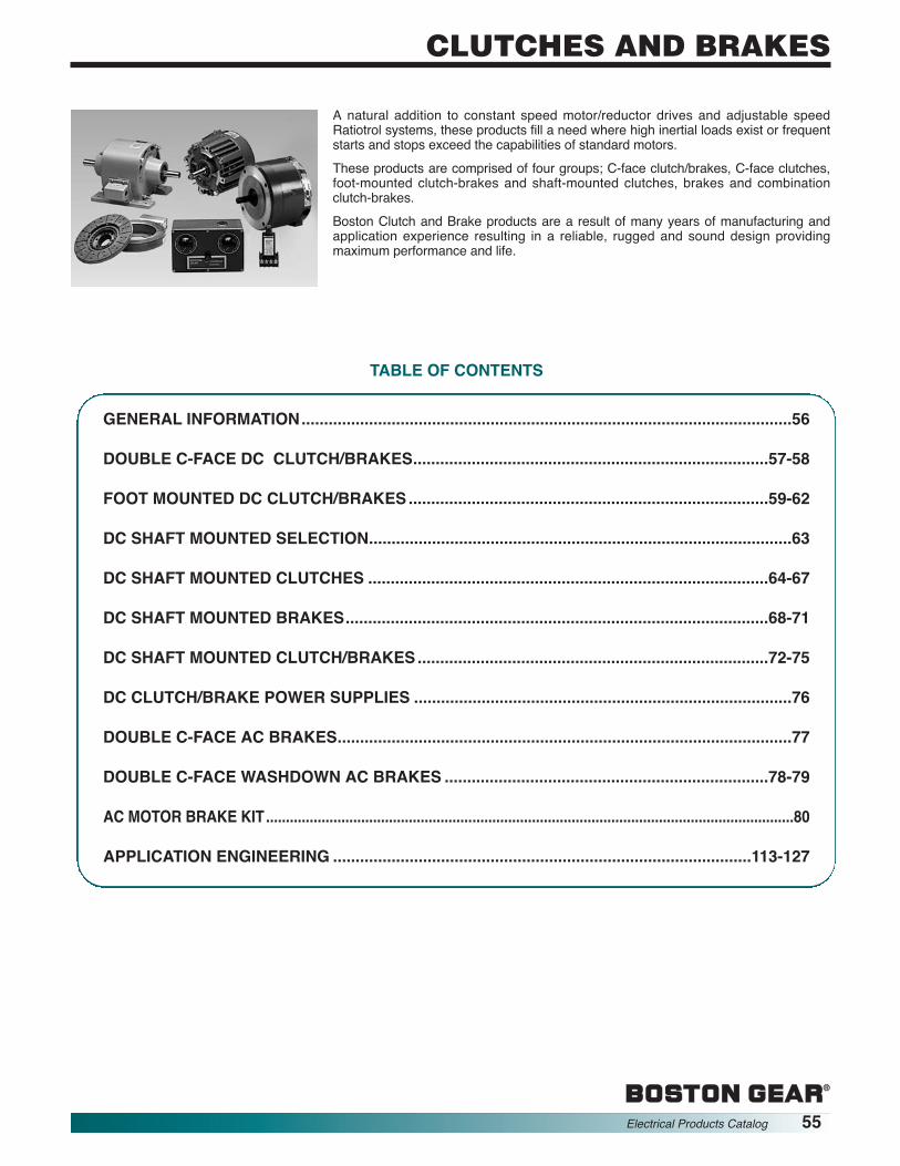
®
CLUTCHES AND BRAKES
®
Electrical Products Catalog 55
A natural addition to constant speed motor/reductor drives and adjustable speedRatiotrol systems, these products fill a need where high inertial loads exist or frequentstarts and stops exceed the capabilities of standard motors.These products are comprised of four groups; C-face clutch/brakes, C-face clutches,foot-mounted clutch-brakes and shaft-mounted clutches, brakes and combinationclutch-brakes.Boston Clutch and Brake products are a result of many years of manufacturing andapplication experience resulting in a reliable, rugged and sound design providingmaximum performance and life.
TABLE OF CONTENTS
GENERAL INFORMATION.............................................................................................................56
DOUBLE C-FACE DC CLUTCH/BRAKES...............................................................................57-58
FOOT MOUNTED DC CLUTCH/BRAKES................................................................................59-62
DC SHAFT MOUNTED SELECTION..............................................................................................63
DC SHAFT MOUNTED CLUTCHES .........................................................................................64-67
DC SHAFT MOUNTED BRAKES..............................................................................................68-71
DC SHAFT MOUNTED CLUTCH/BRAKES..............................................................................72-75
DC CLUTCH/BRAKE POWER SUPPLIES ....................................................................................76
DOUBLE C-FACE AC BRAKES.....................................................................................................77
DOUBLE C-FACE WASHDOWN AC BRAKES ........................................................................78-79
AC MOTOR BRAKE KIT.....................................................................................................................................80
APPLICATION ENGINEERING .............................................................................................113-127

®
56 Electrical Products Catalog
CLUTCHES AND BRAKES
These are a few common applications. Clutches andBrakes may be used wherever control of linear or rotarymotion starts and stops are required.Electric clutches and brakes perform controlled start and stopfunctions between a constantly-running prime mover and aload. Electrical commands are generated manually(pushbutton) or automatically (switch, photocell, tape,sequence programmer, etc.)
CLUTCH – AccelerationNO SHOCKIn this split-shaft application,the field and rotor aremounted to a motor and thearmature to a reducer inputshaft. A low setting of thepotentiometer on the controlallows the clutch to engagethe reducer worm gearssmoothly, eliminating shockto the machine system.HIGH RESPONSEIn this thru-shaft application,the potentiometer is set tofull current. Engaging theclutch produces millisecondpower transmission frommotor to driven shaft.REVERSINGIn this application, therotational direction of thedriven shaft is determined byengaging different clutches.SPEED CHANGINGThe speed of the driven shaftis determined by engagingthe appropriate clutch.
CLUTCH & BRAKE BASICSDC clutches and brakes are magnetically-activatedmechanical power transmission members normally installedbetween a motor shaft and driven shaft – either a speedreducer or the final driven shafts.Both a clutch and brake transmit torque mechanically inresponse to an electricalsignal.In a clutch, a disc on arevolving shaft is connectedby magnetic attraction to adisc on a stationary shaftthus starting the drive.In a brake, one disc is fixedand magnetic attractionstops the revolving disc.
THE DISCS ARE CONNECTED BY MEANS OF ELECTRO -MAGNETIC ATTRACTION
In a brake, one disc (themagnet) contains a coilembedded in a circularhorseshoe shaped cavity.The other disc (the armature)consists of segments of ironattached to backing plate.A friction face is embeddedin the magnet of the brakebetween the inner pole andthe outer pole. When directcurrent is applied to the coil,magnetic force attracts thearmature to the magnet.In the clutch, the magnet isstationary and the magneticflux passes across an airgapand through a rotating rotorinto the armature.
BRAKE – DecelerationNO SHOCKPotentiometer low: controlledstop.HIGH RESPONSEPotentiometer full: fastprecise stop.
EMERGENCY STOPSignal to brake brings malfunctioning system to a fast stop.HOLDINGFully engaged brake holds machine in stopped position.
CLUTCH/BRAKELINEAR POSITIONINGCarton breaks the beam,disen gaging the clutch,engaging the brake. Carton(counter timer, pressureswitch, etc.) disengages thebrake, engages the clutch.JOGGINGPushbutton IN, clutch is ON;button OUT, clutch isdisengaged and brake is ON.Common in machine setupand registration controls.ROTARY INDEXINGProximity switch disengagesthe clutch, engages thebrake for precise positioning.
CYCLINGProgrammed sequencer alternately engages the clutch andbrake, producing programmed start-stop sequence.
EP02
4A
ARMATUREMAGNET
COIL
TERMINAL OUTER POLE
FRICTIONMATERIAL
INNER POLEFLUX
COIL
COIL ARMATURE
ROTOR EP02
5A
EP02
6A
EP02
8A
EP02
7A
General Information

“CC” clutch and “CBC” clutch/brake modulesmay be mounted directly to NEMA C-facemotors and reducers. (Modules have 90VDCcoils)
NEMA C-Face Mounting
To select the correct module package:
1. Determine the frame size, horsepowerand output rpm of your motor.
2. Choose the right size module from the horsepower versus shaft speed chart and the NEMA mounting flange.
HP Shaft Speed At Clutch (In RPM)100 200 300 400 500 600 700 800 900 1000 1100 1200 1500 1800 2000 2400 3000 3600
1/41/23/41
1-1/2235
7-1/2
56
180
®
Electrical Products Catalog 57
CLUTCHES AND BRAKESC-Face Mounted Clutches - CC Series90 VDC Clutch Brakes - CBC Series
ORDER BY CATALOG NUMBER OR ITEM CODE
CC Series CBC SeriesStatic Maximum Reducer Approx. Weight (lbs) Clutches Clutch BrakesTorque Motor HP NEMA-C Bore CC CBC Catalog Item Catalog Item(Lb. Ft.) 3600 RPM Frame Code Series Series Number Code Number Code
16 1 56C/48Y B5 8.3 10.0CC56-16A 82904CBC56-16A 82907
30 3 143TC, 145TC B7 10.3 13.2CC180-30A 82905CBC180-30A 82908182C, 184C
95 7.5 182TC, 184TC B9 24.3 30.6CC210-95A 82906CBC210-95A 82909213C, 215C
An optional conduit box is available. It has twoconduit connection holes for 1/2” standardconduit connectors.
Horsepower vs. Shaft Speed
180

®
58 Electrical Products Catalog
CLUTCHES AND BRAKESC-Face Mounted Clutches - CC Series90 VDC Clutch Brakes - CBC Series
SIZE* A B C D E F G H
56 - 16A 6.750 4.844 1.813 6.750 .625 .937 2.203 ----
180 - 30A 6.828 4.844 1.891 6.750 .875 .937 2.203 ----
210 - 95A 8.891 5.922 2.500 9.250 1.125 .500 2.203 .500
SIZE* J K L M N
56 - 16A 5.531 2.188 3.250 4.438 6.688180 - 30A 5.531 2.188 3.250 4.438 6.688
210 - 95A 6.859 2.188 3.250 5.766 9.688
* Dimensions are the same for “CC” and “CBC” Series
C
E
B
M
L
K
J
N10
MotorClutch
40OutputClutch
1/2" ConduitHole Both
Ends
F
AG
OptionalConduitBox
D
H
All dimensions are nominal, unless otherwise noted.

®
Electrical Products Catalog 59
CLUTCHES AND BRAKESFoot Mounted Clutch Brakes - CBF Series
90 VDC
CBF Modules are rugged, pre-assembled clutchand brake combinations in an enclosed, footmounted housing.
They are factory aligned and pre-assembled andhave been designed to mate easily with industrystandard motors and reducers with v-belts, pulleys,chain and sprockets, in line couplings and timingbelt drives.
FEATURES
• Bolt-it-down and wire-it-up . . . it’s ready to go!
• Maintenance free
• Torque range from 22.5 lb. ft. to 50 lb. ft.
Meets electrical codesUL Listed or CSA Certified.
Pre-packagedOver 20 majorcomponents havebeen pre-engineeredand pre-assembled ina typical foot mountedmodule. Ready-to-go,straight from the box.
Brake output shaft
Foot mountedBolt-it-down and wire-it-up. Allows forquick replacement/reduced downtime.
Maintenance freeNever needs lubrication.Self-adjusting for wear ofclutch-brake friction faces.Consistent performance.
Clutch input shaft
Heavy duty bearingsProperly aligned for
maximum performance.
TYPICAL APPLICATION
A foot mounted module combines with a motor in aparallel shaft drive application.

SELECTION PROCEDURE
HP Shaft Speed At Clutch (In RPM)100 200 300 400 500 600 700 800 900 1000 1100 1200 1500 1800 2000 2400 3000 3600 4000
1/201/121/81/61/41/31/23/41
1-1/223
®
60 Electrical Products Catalog
CLUTCHES AND BRAKESFoot Mounted Clutch Brakes - CBF Series
90 VDC
Horsepower vs. Shaft Speed
Determine the shaft speed at the clutch/brake module. The number listed at the intersectionof horsepower and speed is the size clutch/brake module you require.
Static Approx. Totally EnclosedTorque Max. Weight Catalog Item(Lb. Ft.) RPM (Lbs.) Number Code
22.5 4500 19.7 CBF22A 8290250* 4000 56 CBF50A 82903
ORDER BY CATALOG NUMBER OR ITEM CODE
*Clutch is rated 40 Lb. Ft., brake is rated 50 Lb. Ft.
CBF22A
CBF50A

®
Electrical Products Catalog 61
CLUTCHES AND BRAKESFoot Mounted Clutch Brakes - CBF Series
90 VDC
EP-170, 250, 400 Dim 111/11/99page 114
Output
A
B
C
D
H
E
G
F E
D
C
B
Input
Brake ClutchO
EP-170, 250, 400 Dim 211/11/99page 115
MN
L
K
J
I
Size A B C Min. D E F G Max. H
CBF22A3/16 x 3/16 x .7495
1.875 3.515 4.593 2.500 11.781.312 Wide
1-1/2 .7485 (4 slots)
Inertia-WR (lb-in2)Size Static Torque (lb. ft.)Output Input
Max. RPM Weight lbs.
CBF22A 270 2.566 2.222 19.7
SPECIFICATIONS
Size I J K L M N O
CBF22A 6.937.3474
.500 2.578 5.156 6.000.3464 1/2 conduit x 2
4500

®
62 Electrical Products Catalog
CLUTCHES AND BRAKESFoot Mounted Clutch Brakes - CBF Series
90 VDC
Brake Clutch
InputOutputA
D
C C
O
E F E
G
B
H
N
ML K
J
I
Size A B Dia. C Min. D Max. Dia. E F G Max.
CBF50A3/16 X 3/16 .8750
2.218 3.796 4.234 7.000 15.5151-3/4 .8745
Size H Dia. I J K L M N Max. O
CBF50A.406
8.2184.004
5.00 2.937 5.875 8.734 1/2 conduit x 2(4 holes) 3.992
Size Unit Static Torque (lb. ft.) Inertia-WR2(lb-ft2) Max. RPM Weight lbs.
CBF50AClutch 50
2.222 4000 56Brake 40
SPECIFICATIONS
Output Input.063 .039

®
Electrical Products Catalog 63
CLUTCHES AND BRAKES
Clutch and brake components for shaft-mounting provide flexible arrangements tosatisfy almost any mechanical arrangement where power transmission capabilitiesare required.The most common arrangement is the bearing-mounted split-shaft application usedto couple two in-line shafts.Clutches for through-mounting utilize bearing mounted sprockets or pulleys to driveparallel shafts.Brakes are flanged mounted with the field held stationary on a machine member.Clutch brakes are bearing-mounted for split-shaft coupling.For application engineering see Pages 113-127.
CLUTCH, BEARING-MOUNTED, SPLIT SHAFT(TYPE S)Clutches consist of a field, rotor, armature and its hub. Thefield is mounted on sealed ball bearings and remainsstationary while the rotor revolves. The rotor extends throughthe field assembly and is attached to the drive shaft by abushing, in many sizes. A small tab holds the field stationary.The armature is mounted on a splined hub held on the shaftby standard tapered bushings.
CLUTCH, BEARING MOUNTED, THROUGHSHAFT (TYPE T)The through-shaft mounting of the field and rotor is asdescribed for the split-shaft version. The armature in thisapplication is mounted to a bearing mounted sheave, sprocketor gear. A special sheave adapter is necessary to assist in themounting of the armature sheave. (Typical C50 and larger)
BRAKE, FLANGE MOUNTEDThe magnet is mounted to a machine member, or a stationarymounting plate by inner or outer mounted flanges. The spaceavailable determines which flange to use. Terminals are wireddirectly to the brake control terminals. The armature rides on asplined drive hub. Standard tapered bushings secure the hubto the rotating shaft, in most units.
CLUTCH BRAKEWhen the clutch field is energized and the brake coil is de-energized, the clutch and brake armatures rotate with thedrive shaft. When the clutch coil is de-energized and the brakecoil energized, the two armatures are stopped. The rotorcontinues to turn. Operation is the same whether the clutch isbearing or flange mounted.
FIELD TAB
BALL BEARING
BUSHING
DRIVING SHAFT
AIR GAP
DRIVEN SHAFT
ARMATURE
ARMATUREHUB
EP034A
ROTOR
FIELD
ARMATUREBEARING-MOUNTED SHEAVE
SHEAVE ADAPTER
EP035A
TERMINAL
COIL
MAGNET
ARMATURE HUB
OUTER POLEARMATURE
INNER POLE
RELEASE SPRING
KEY
BUSHING
FRICTION MATERIAL
OUTER MOUNTED FLANGE
FIELD
ROTOR
MAGNET
ARMATURE
DRIVING SHAFT
DOUBLEARMATURE HUB
DRIVEN SHAFT
DC Shaft Mounted Selection
DRIVING SHAFTDRIVEN SHAFT

®
64 Electrical Products Catalog
CLUTCHES AND BRAKES
RATINGSStatic Torque: 20 Lb. Ft.Maximum Speed: 4500 RPMVoltage: 90 VDCResistance at 20°C: 1087 ±5% ohmsMaximum Current: .087 AmpsMaximum Watts: 7.83Coil Build-up: 95 msCoil Decay: 23 ms
INSTALLATION REQUIREMENTS — C20SAngular alignment of shafts within .006" TIR at 5" diameterArmature mounting shaft concentric with rotor mounting shaft within .003" TIR
SPLIT SHAFT MODELS — C20S THROUGH SHAFT MODELS — C20T
EP037A
2.9582.918
1.9481.928
.068
.058.405.345
.198
.178
1.6041.584DIA.
1.1981.178
1.6301.620
3
1
2
4.2604.240DIA.
2- #1/4-20UNCSET SCREWS
.198
.1782- #1/4-20UNCSET SCREWS
.024 NOMINALAIR GAP
EP038A
3.8333.793
1.9481.928
.068
.058.405.345
1.6301.620
3
4.2604.240DIA.
.198
.1782- #1/4-20UNCSET SCREWS
.024 NOMINALAIR GAP
1.010.990
2.2032.173
12
.3145
.3125
1.1351.115
.073
.053
1.2011.186
1.3761.375DIA.
+
+
+ +
+
+
2.272
2.232
AB
50°40°
.220.20
0
.520.48
0
35°25°
EP03
9A
2.521
2.479
AVERAGE WEIGHTS AND INERTIAS
ALL DIMENSIONS IN INCHES ORDER BY ITEM CODE
Part Wt. (lbs.) Inertia (lb ft2)Field and Rotor 3.890 —Field 2.343 —Rotor 3/4 bore 1.547 .0159
Armature .815 .0151Armature hub (C20S) .604 .0023Armature hub (C20T) .802 .0023Total C20S 5.309Total C20T 5.507
STANDARD BORES KEYWAY DIMENSIONS* ITEM CODESNo. 1 No. 2 No. 3 Field and
Armature Armature Hub Rotor AssemblyNominal Actual Keyway A B C20S/C20T C20S C20T C20S/C20T
1/2 .5005/.5015 1/8 × 1/16 .560/.565 .126/.128 45062 45067 450705/8 .6255/.6270 3/16 × 3/32 .709/.715 .188/.190 45063 45068 450713/4 .7505/.7520 3/16 × 3/32 .837/.845 .188/.190 45061 45064 45069 45072
7/8† .8755/.8770 3/16 × 3/32 .964/.970 .188/.190 45065 — 45073†1 † 1.0005/1.0020 1/4 × 1/8 1.114/1.122 .251/.253 45066 — 45074†
*Armature Hub Data not applicable to C20T.†Not applicable to C20T.HOW TO ORDER: Specify Item Codes for Armature, Armature Hub (desired bore) and Field and Rotor Assembly (desired bore) for desired Type, C20S or C20T.
Clutches C20 Series90 VDC

®
Electrical Products Catalog 65
CLUTCHES AND BRAKES
*Two required for C50S Models, one for C50T Models.†Not applicable to C50T Models.HOW TO ORDER: Specify Item Codes for Armature, Armature Hub (desired bore), Field and Rotor Assembly and Bushing (desired bore and quantity required) fordesired Type, C50S or C50T.
RATINGSStatic Torque: 50 Lb. Ft.Maximum Speed: 4000 RPMVoltage: 90 VDCResistance at 20°C: 237 ±5% ohmsMaximum Current: 400 AmpsCoil Build-up: 70 msCoil Decay: 15 ms
INSTALLATION REQUIREMENTS — C50SRotor shaft concentric with armature shaft within .004" TIRAngular misalignment of shafts within .008" TIR at 5"diameter.
SPLIT SHAFT MODELS — C50S
1/2-1" BORES
1-1/8" & 1-1/4" BORES
THROUGH SHAFT MODELS — C50T
EP040A
.420
.2742.5822.562
1.8011.781
.031 NOMINALAIR GAP.420
.274
41.016.984
1.9681.978DIA.
5.3235.303DIA.
42
.188
.150 .188.150
1.016.984
31
3.7983.410
.068
.058
EP041A
.031 NOMINALAIR GAP
1.5051.4951.989
1.949DIA.
5.3235.303DIA.
.198
.178.198.178
1
2.1042.084
.068
.058
1.3231.303
2
.405
.345
2-#1/4-20 UNCSET SCREWS
3
3.2393.199
2-#1/4-20 UNCSET SCREWS
1.9601.940DIA.
1.8771.875
PILOT DIA.
.269
.264 DIA. 4HOLESEQUALLYSPACED ON A1.570/1.556 B.C.
2.5822.562
1.8011.781
.031 NOMINALAIR GAP
.099
.084
.979
.9591.109MIN.
1
2
5.3235.303DIA.
EP04
2A
+
+
+
+
B
50°40° 35°25°
.510
.490.220.200
3.1443.104 2.897
2.853
A
+ +
AVERAGE WEIGHTS AND INERTIASPart Wt. (lbs.) Inertia (lb ft2)Field and Rotor Assy 6.074 —Field 3.408 —Rotor 3/4" bore 2.666 .053
Armature 1.516 .044Armature hub & 3/4" bushing .958 .005Total 8.548 —
STANDARD BORES KEYWAY DIMENSIONS ITEM CODESNo. 1 No. 2 No. 3 Field and No. 4
Armature Armature Hub Rotor Assembly Bushing*Nominal Actual Keyway A B C50S/C50T C50S C50T C50S C50T C50S/C50T
1/2 .5000/.5015 — .555/.565 .124/.126 451635/8 .6250/.6265 — .704/.714 .1865/.1885 451643/4 .7500/.7515 — .832/.842 .1865/.1885 45092 45092 45095 45095 451657/8 .8750/.8765 — .959/.969 .1865/.1885 45091 45166
1 1.0000/1.0015 — 1.110/1.120 .250/.252 451671-1/8† 1.1255/1.1270 1/4 × 1/8 1.241/1.251 .251/.253 45093 — 45096 — —1-1/4† 1.2505/1.2520 1/4 × 1/8 1.367/1.377 .251/.253 45094 — 45097 — —
ALL DIMENSIONS IN INCHES
Clutches C50 Series90 VDC
ORDER BY ITEM CODE

®
66 Electrical Products Catalog
CLUTCHES AND BRAKES
RATINGSStatic Torque: 100 Lb. Ft.Maximum Speed: 3600 RPMVoltage: 90 VDCResistance at 20°C: 202 ±5% ohmsMaximum Current: .469 AmpsMaximum Watts: 42.3Coil Build-up: 65 msCoil Decay: 15 ms
INSTALLATION REQUIREMENTSRotor shaft concentric with armature shaft within .004" TIRAngular misalignment of shafts within .008" TIR at 5" diameter
SPLIT SHAFT MODELS — C100STHROUGH SHAFT MODELS — C100T
1.2661.234
EP044A
3.7683.533
3.2233.183 2.020
1.980 .241.161.130
.120
3
44
2
1
.188
.1506.6716.641DIA.
1.2661.234
.031 NOMINALAIR GAP
EP25
4A
3.2233.183 2.021
1.880.130.120
.274
.264 DIA. 6 HOLES EQUALLYSPACED ON A2.007/1.993 B.C.
.031 NOMINAL AIR GAP
1
23
4
.241
.161
1.2341.266
1.2091.169
.130
.1206.6716.641
2.502 PILOT2.500 DIA.
A
B
40°50° 25°
35°
4.2804.220
4.6294.559
.885
.855
EP045A
AVERAGE WEIGHTS AND INERTIASPart Wt. (lbs.) Inertia (lb ft2)Field and Rotor Assy 10.90 —Field 6.25 —Rotor 3/4" bore 4.65 .123
Armature 2.43 .115Armature hub & 3/4"bushings 1.79 .015
Total 15.12
STANDARD BORES KEYWAY DIMENSIONS ITEM CODESNo. 1 No. 2 No. 3 Field and No. 4
Armature Armature Hub Rotor Assembly Bushing*Nominal Actual A B C100S/C100T C100S/C100T C100S/C100T C100S/C100T
1/2 .5000/.5015 .555/.565 .124/.126 451685/8 .6250/.6265 .704/.714 .1865/.1885 451693/4 .7500/.7515 .832/.842 .1865/.1885 451707/8 .8750/.8765 .959/.969 .1865/.1885 45171
1 1.0000/1.0015 1.110/1.120 .249/.251 45119 45120 45121 451721-1/8 1.125/1.127 1.236/1.246 .249/.251 451731-1/4 1.250/1.252 1.300/1.310 .249/.251 451741-3/8 1.375/1.377 1.419/1.429 .3115/.3135 451751-1/2 1.500/1.502 1.540/1.570 .375/.377 45176
*Two required for C100S Models, one for C100T Models.HOW TO ORDER: Specify Item Codes for Armature, Armature Hub, Field and Rotor Assembly and Bushing (desired bore and quantity required) for desired type,C100S or C100T.
ALL DIMENSIONS IN INCHES ORDER BY ITEM CODE
Clutches C100 Series90 VDC

®
Electrical Products Catalog 67
CLUTCHES AND BRAKES
RATINGSStatic Torque: 150 Lb. Ft.Maximum Speed: 3600 RPMVoltage: 90 VDCResistance at 20°C: 219 ±5% ohmsMaximum Current: .433 AmpsMaximum Watts: 39Coil Build-up: 155 msCoil Decay: 36 ms
INSTALLATION REQUIREMENTSRotor shaft concentric with armature shaft within .006" TIRAngular misalignment of shafts within .010" TIR at 8" diameter
SPLIT SHAFT MODELS — C150STHROUGH SHAFT MODELS — C150T
EP047A
4
3
4
2
1
.248
.168
.130
.120
2.2862.246
3.5883.538
4.1013.856
.188
.150
2.4942.484
8.6098.564DIA.
DIA. 1.2661.234
1.2661.234
.039 NOMINALAIR GAP
EP049A
1.3331.293 1.266
1.234
.039 NOMINALAIR GAP
12 3
4
.248
.168
.130
.120
2.2862.246
3.5883.538
.161
.151
3.127 PILOT3.125 DIA.
8.6098.564DIA.
.340
.3306 HOLESEQUALLYSPACED ON2.4452.431
DIA.
DIA. B.C.
B
25°15°
A
50°40°
.895
.855
.350.342 DIA.
5.3795.3095.030
4.970
AVERAGE WEIGHTS AND INERTIASPart Wt. (lbs.) Inertia (lb ft2)Field and Rotor Assy 18.33 —Field 10.85 —Rotor 3/4" bore 7.48 .354
Armature 4.85 .326Armature hub & 3/4"bushings 2.74 .033
Total 25.92
STANDARD BORES KEYWAY DIMENSIONS ITEM CODESNo. 1 No. 2 No. 3 Field and No. 4
Armature Armature Hub Rotor Assembly Bushing*Nominal Actual A B C150S/C150T C150S/C150T C150S/C150T C150S/C150T
1/2 .5000/.5015 .555/.565 .124/.126 451685/8 .6250/.6265 .704/.714 .1865/.1885 451693/4 .7500/.7515 .832/.842 .1865/.1885 451707/8 .8750/.8765 .959/.969 .1865/.1885 45171
1 1.0000/1.0015 1.110/1.120 .249/.251 45136 45137 45138 451721-1/8 1.125/1.127 1.236/1.246 .249/.251 451731-1/4 1.250/1.252 1.300/1.310 .249/.251 451741-3/8 1.375/1.377 1.419/1.429 .3115/.3135 451751-1/2 1.500/1.502 1.540/1.570 .375/.377 45176
*Two required for C150S Models, one for C150T Models.HOW TO ORDER: Specify Item Codes for Armature, Armature Hub, Field and Rotor Assembly and Bushing (desired bore and quantity required) for desired typeC150S or C150T.
ALL DIMENSIONS IN INCHES ORDER BY ITEM CODE
Clutches C150 Series90 VDC

®
68 Electrical Products Catalog
CLUTCHES AND BRAKES
HOW TO ORDER: Specify Item Codes for Armature, Armature Hub (desired bore), Field Assembly, and Field Mounting Hardware.
RATINGSStatic Torque: 20 Lb. Ft.Maximum Speed: 4500 RPMVoltage: 90 VDCResistance at 20°C: 1087 ±5% ohmsMaximum Current: .087 AmpsMaximum Watts: 7.83Coil Build-up: 100 msCoil Decay: 22 ms
INSTALLATION REQUIREMENTSSquareness of brake mounting surface with armature shaft within .006" TIR at 5" diameter.Concentricity of brake mounting pilot diameter with armature shaft within .006" TIR.
2.2392.199
2
1.6041.584DIA.
1.874 PILOT–––––1.873 DIA1.1981.178
.099
.089
1.2291.209 60
REF
1
5
3
4-# 1/4-20 UNCCAP SCREWS
.198
.178
2-#1/4-20 UNCCAP SCREWS
4.2604.240DIA.
.024 NOMINALAIR GAP
EP05
1A
B
A
35°25°
5.625 PILOT DIA.5.623
4.2604.240SQUARE
.296
.280DIA. 4 HOLES EQUALLYSPACED ON 5.010
4.990 B.C.
AVERAGE WEIGHTS AND INERTIASPart Wt. (lbs.) Inertia (lb ft2)Field 2.586 —Armature .815 .0151Armature hub .604 .0023Total 4.005 .0174
STANDARD BORES KEYWAY DIMENSIONS ITEM CODESNo. 3 No. 5
No. 2 Field Assembly Field MountingNo. 1 Armature Outside Hardware
Nominal Actual Keyway A B Armature Hub Mounted Outside Mounting1/2 .5005/.5015 1/8 × 1/16 .560/.565 .126/.128 450625/8 .6255/.6270 3/16 × 3/32 .709/.715 .188/.190 450633/4 .7505/.7520 3/16 × 3/32 .837/.845 .188/.190 45061 45064 45075 450817/8 .8755/.8770 3/16 × 3/32 .964/.970 .188/.190 45065
1 1.0005/1.0020 1/4 × 1/8 1.114/1.122 .251/.253 45066
ALL DIMENSIONS IN INCHES ORDER BY ITEM CODE
Brakes B20 Series90 VDC

®
Electrical Products Catalog 69
CLUTCHES AND BRAKES
HOW TO ORDER: Specify Item Codes for Armature, Armature Hub (desired bore), Field Assembly, (inside or outside mounting) Bushing (desired bore) and FieldMounting Hardware.
RATINGSStatic Torque: 50 Lb. Ft.Maximum Speed: 4000 RPMVoltage: 90 VDCResistance at 20°C: 237 ±5% ohmsMaximum Current: .400 AmpsMaximum Watts: 36Coil Build-up: 65 msCoil Decay: 13 ms
INSTALLATION REQUIREMENTSSquareness of brake mounting surface with armature shaft within .006" TIR at 4" diameter.Concentricity of brake mounting pilot diameter with armature shaft within .010" TIR.
EP05
4A
A
B
6.5006.498 PILOT DIA.
4.150MAX.
2.8852.865
5.0104.990SQ.
INSIDE MOUNTED.181.187 DIA. 8 HOLES
EQUALLY SPACED ON 2.385 / 2.365 DIA.B.C.
OUTSIDE MOUNTED
4 HOLES EQUALLY SPACEDON 5.885 / 5.865 DIA.B.C.
.399
.389 DIA.
1
1.2601.240
2.7702.740DIA.
2.0832.043
.652
.592
24 1.968
1.978DIA.
OUTSIDEMOUNTED
INSIDEMOUNTED
.420
.273
1.2911.271.031 NOMINAL AIR GAP
.887
.863DIA.
.188
.150
2.6902.465
.768
.744
1.2661.234
PILOTDIA.
2.0652.063
3
3
5
5.3235.303DIA.
1
1.2601.240
2.7702.740DIA.
.652
.592
2
1.9891.949DIA.
OUTSIDEMOUNTED
INSIDEMOUNTED
1.2911.271
.031 NOMINAL AIR GAP
.887
.863DIA.
.198
.178
2.4262.386
.768
.744
PILOTDIA.
2.0652.063
3
3
5
5.3235.303DIA.
2 #1/4-20 UNCSET SCREWS
.130
.1201.3231.303
AVERAGE WEIGHTS AND INERTIASPart Wt. (lbs.) Inertia (lb ft2)Field 3.763 —Armature 1.516 .044Armature hub .958 .005Total 6.237 .049
STANDARD BORE KEYWAY DIMENSIONS ITEM CODESNo. 5
Field MountingNo. 2 No. 3 Hardware
No. 1 Armature Field Assembly No. 4 Inside OutsideNominal Actual Keyway A B Armature Hub Inside Outside Bushing Mounting Mounting
1/2 .5000/.5015 — .555/.565 .124/.126 451635/8 .6250/.6265 — .704/.714 .1865/.1885 451643/4 .7500/.7515 — .832/.842 .1865/.1885 45092 451657/8 .8750/.8765 — .959/.969 .1865/.1885 45091 45098 45099 45166 45107 451081 1.0000/1.0015 — 1.110/1.120 .250/.252 45167
1-1/8 1.1255/1.1270 1/4 × 1/8 1.241/1.251 .251/.253 45093 —1-1/4 1.2505/1.2520 1/4 × 1/8 1.367/1.377 .251/.253 45094 —
1/2" To 1" MODELS 1-1/8" AND 1-1/4" MODELS
ALL DIMENSIONS IN INCHES ORDER BY ITEM CODE
Brakes B50 Series90 VDC

®
70 Electrical Products Catalog
CLUTCHES AND BRAKES
HOW TO ORDER: Specify Item Codes for Armature, Armature Hub, Field Assembly (inside or outside mounting), Bushing (desired bore) and Field MountingHardware.
RATINGSStatic Torque: 100 Lb. Ft.Maximum Speed: 3600 RPMVoltage: 90 VDCResistance at 20°C: 202 ±5% ohmsMaximum Current: .469 AmpsMaximum Watts: 42.3Coil Build-up: 76 msCoil Decay: 12 ms
INSTALLATION REQUIREMENTSSquareness of brake mounting surface with armature shaft within .006" TIR at 5" diameter.Concentricity of brake mounting pilot diameter with armature shaft within .010" TIR.
3.0342.799
1
2
4
3
5
INSIDE MOUNTED
OUTSIDEMOUNTED
.188
.150
2.4892.449
1.2601.240
1.2661.234
.031 NOMINAL AIR GAP 1.2811.251
.887
.863
.717
.677
3.9573.917DIA.
2.8222.820PILOT DIA.
.652
.592
6.6346.594DIA. EP
056A
B
.358
.338
4.703MAX.
2.8852.865
6.5836.543
SQUARE
INSIDE MOUNTED.358.338 DIA. 4 HOLES EQUALLY SPACED
ON 3.698 / 3.678 DIA.B.C.
OUTSIDE MOUNTED
4 HOLES EQUALLY SPACEDON 7.260 / 7.240 DIA. B.C.
8.0007.998 PILOT DIA.
A
DIA.
AVERAGE WEIGHTS AND INERTIASPart Wt. (lbs.) Inertia (lb ft2)Field 4.85 —Armature 2.43 .115Armature hub 1.79 .015Total 9.07 .130
STANDARD BORE KEYWAY DIMENSIONS ITEM CODESNo. 5
No. 3 Field MountingNo. 2 Field Assembly Hardware
No. 1 Armature Inside Outside No. 4 Inside OutsideNominal Actual A B Armature Hub Mounted Mounted Bushing Mounting Mounting1/2 .5000/.5015 .555/.565 .124/.126 451685/8 .6250/.6265 .704/.714 .1865/.1885 451693/4 .7500/.7515 .832/.842 .1865/.1885 451707/8 .8750/.8765 .959/.969 .1865/.1885 451711 1.0000/1.0015 1.110/1.120 .249/.251 45119 45120 45122 45123 45172 45124 45124
1-1/8 1.125/1.127 1.236/1.246 .249/.251 451731-1/4 1.250/1.252 1.300/1.310 .249/.251 451741-3/8 1.375/1.377 1.419/1.429 .3115/.3135 451751-1/2 1.500/1.502 1.540/1.570 .375/.377 45176
ALL DIMENSIONS IN INCHES ORDER BY ITEM CODE
Brakes B100 Series90 VDC

®
Electrical Products Catalog 71
CLUTCHES AND BRAKES
HOW TO ORDER: Specify Item Codes for Armature, Armature Hub (desired bore), Field Assembly (inside or outside mounting), Bushing (desired bore) and FieldMounting Hardware.
RATINGSStatic Torque: 150 Lb. Ft.Maximum Speed: 3600 RPMVoltage: 90 VDCResistance at 20°C: 219 ±5% ohmsMaximum Current: .433 AmpsMaximum Watts: 39Coil Build-up: 110 msCoil Decay: 20 ms
INSTALLATION REQUIREMENTSSquareness of brake mounting surface with armature shaft within .006" TIR at 6" diameter.Concentricity of brake mounting pilot diameter with armature shaft within .010" TIR.
1
2
4
3
5
2.6342.584
1.2661.234
1.2661.234
.039 NOMINAL AIR GAP
1.3181.298
.887
.863
.739
.699
4.7444.704DIA.
3.5033.501PILOT DIA.
.652
.592
8.6098.564DIA.
3.1482.903
.188
.150
2.4942.484DIA.
.130
.120
EP05
8A
B
.358
.338
2.8852.865
8.0207.980
SQUARE
INSIDE MOUNTED.358.338 DIA. 6 HOLES EQUALLY SPACED
ON
OUTSIDE MOUNTED4 HOLES EQUALLY SPACEDON 8.885 B.C.
9.7499.747 PILOT DIA.
A
DIA.
B.C.
5.625 MAX.
8.865
4.2604.240
AVERAGE WEIGHTS AND INERTIASPart Wt. (lbs.) Inertia (lb ft2)Field 8.46 —Armature 4.85 .326Armature hub 2.74 .033Total 16.05 .359
STANDARD BORE KEYWAY DIMENSIONS ITEM CODESNo. 5
No. 3 Field MountingNo. 2 Field Assembly Bushing Hardware
No. 1 Armature Inside Outside No. 4 Inside OutsideNominal Actual A B Armature Hub Mounted Mounted Bushing Mounting Mounting
1/2 .5000/.5015 .555/.565 .124/.126 451685/8 .6250/.6265 .704/.714 .1865/.1885 451693/4 .7500/.7515 .832/.842 .1865/.1885 451707/8 .8750/.8765 .959/.969 .1865/.1885 451711 1.0000/1.0015 1.110/1.120 .249/.251 45136 45137 45139 45140 45172 45141 45124
1-1/8 1.125/1.127 1.236/1.246 .249/.251 451731-1/4 1.250/1.252 1.300/1.310 .249/.251 451741-3/8 1.375/1.377 1.419/1.429 .3115/.3135 451751-1/2 1.500/1.502 1.540/1.570 .375/.377 45176
ALL DIMENSIONS IN INCHES ORDER BY ITEM CODE
Brakes B150 Series90 VDC
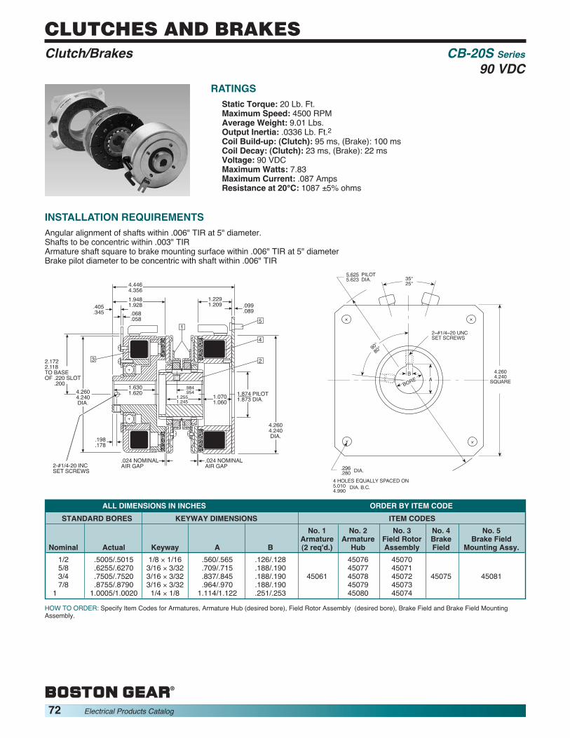
®
72 Electrical Products Catalog
CLUTCHES AND BRAKES
HOW TO ORDER: Specify Item Codes for Armatures, Armature Hub (desired bore), Field Rotor Assembly (desired bore), Brake Field and Brake Field MountingAssembly.
RATINGSStatic Torque: 20 Lb. Ft.Maximum Speed: 4500 RPMAverage Weight: 9.01 Lbs.Output Inertia: .0336 Lb. Ft.2Coil Build-up: (Clutch): 95 ms, (Brake): 100 msCoil Decay: (Clutch): 23 ms, (Brake): 22 msVoltage: 90 VDCMaximum Watts: 7.83Maximum Current: .087 AmpsResistance at 20°C: 1087 ±5% ohms
4.4464.356
1.874 PILOT1.873 DIA.
1.9481.928.068.058
.405
.345
1.2291.209 .099
.089
15
4
3
.198
.178
2-#1/4-20 INCSET SCREWS
.024 NOMINALAIR GAP
1.6301.620
.024 NOMINALAIR GAP
.984
.9541.0701.060
2
1.2551.245
4.2604.240DIA.
2.1722.118TO BASEOF .220 SLOT .200
4.2604.240DIA.
EP06
0A
AB
BORE A
2–#1/4–20 UNCSET SCREWS
4.2604.240
SQUARE
.296
.280 DIA.
4 HOLES EQUALLY SPACED ON5.0104.990 DIA. B.C.
5.6255.623
PILOTDIA. 35°
25°
90°80°
STANDARD BORES KEYWAY DIMENSIONS ITEM CODESNo. 1 No. 2 No. 3 No. 4 No. 5
Armature Armature Field Rotor Brake Brake FieldNominal Actual Keyway A B (2 req'd.) Hub Assembly Field Mounting Assy.
1/2 .5005/.5015 1/8 × 1/16 .560/.565 .126/.128 45076 450705/8 .6255/.6270 3/16 × 3/32 .709/.715 .188/.190 45077 450713/4 .7505/.7520 3/16 × 3/32 .837/.845 .188/.190 45061 45078 45072 45075 450817/8 .8755/.8790 3/16 × 3/32 .964/.970 .188/.190 45079 45073
1 1.0005/1.0020 1/4 × 1/8 1.114/1.122 .251/.253 45080 45074
INSTALLATION REQUIREMENTSAngular alignment of shafts within .006" TIR at 5" diameter.Shafts to be concentric within .003" TIRArmature shaft square to brake mounting surface within .006" TIR at 5" diameterBrake pilot diameter to be concentric with shaft within .006" TIR
ALL DIMENSIONS IN INCHES ORDER BY ITEM CODE
Clutch/Brakes CB-20S Series90 VDC

®
Electrical Products Catalog 73
CLUTCHES AND BRAKES
HOW TO ORDER: Specify Item Codes for Armatures, Armature Hub (desired bore), Field Rotor Assembly (desired bore), Brake Field (inside or outside mounting),Brake Field Mounting Hardware and Bushing (desired bore).
RATINGSStatic Torque: 50 Lb. Ft.Maximum Speed: 4000 RPMAverage Weight: 14.31 Lbs.Output Inertia: .0955 Lb. Ft.2Coil Build-up: (Clutch): 70 ms, (Brake): 65 msCoil Decay: (Clutch): 15 ms, (Brake): 12 msVoltage: 90 VDCMaximum Watts: 34Maximum Current: .38 AmpsResistance at 20°C: 237 ±5% ohms
5.2304.945
.068
.058
1.2601.240
.652
.592
1
.768
.744
.887.863
DIA.
4
5
2
.120.130
2.065 PILOT2.063 DIA. 2.770
2.740DIA.
1.1401.130
5.3235.303DIA.
5
1.2911.271
1,1031.063
1.8551.845
.031.031NOMINALAIR GAP
NOMINALAIR GAP
1.8011.781
.420
.274
6
5.3235.303DIA.
1.9781.968
DIA. 1.016.984
3
2.7972.743To BaseOf Slot.220.200
EP06
2A
6.5006.498 PILOT DIA.
4.150MAX.
2.8852.865
5.0104.990
SQUARE
OUTSIDEMOUNTED
4 HOLES EQUALLY SPACEDON DIA.B.C.
.399
.389 DIA.
B
BORE
85°75°
2–#1/4–UNCSET SCREWS
A
5.8835.867
INSIDE MOUNTED
.181
.1878 HOLES EQUALLYSPACED ON2.3852.365 DIA.B.C.
DIA.
STANDARD BORES KEYWAY DIMENSIONS ITEM CODESNo. 5 Brake
No. 3 No. 4 Field MountingNo. 1 No. 2 Field Brake Field Hardware
Armature Armature Rotor Inside Outside Inside Outside No. 6Nominal Actual A B (2 Req’d.) Hub Assembly Mounted Mounted Mounting Mounting Bushing
1/2 .5000/.5015 .555/.565 .124/.126 45100 451635/8 .6250/.6265 .704/.714 .1865/.1885 45101 451643/4 .7500/.7515 .832/.842 .1865/.1885 45102 45095 451657/8 .8750/.8765 .959/.969 .1865/.1885 45091 45103 45098 45099 45107 45108 451661 1.0000/1.0015 1.110/1.120 .250/.252 45104 45167
1-1/8 1.1255/1.1270 1.241/1.251 .251/.253 45105 45096 —1-1/4 1.2505/1.2520 1.367/1.377 .251/.253 45106 45097 —
INSTALLATION REQUIREMENTSAngular alignment of shafts within .008" TIR at 5" diameter.Shafts to be concentric within .004" TIRArmature shaft square to brake mounting surface within .006" TIR at 5" diameterBrake pilot diameter to be concentric with shaft within .010" TIR
ALL DIMENSIONS IN INCHES ORDER BY ITEM CODE
Clutch/Brakes CB-50S Series90 VDC

®
74 Electrical Products Catalog
CLUTCHES AND BRAKES
HOW TO ORDER: Specify Item Codes for Armatures, Armature Hub Field Rotor Assembly, Bushing (desired bore), Brake Field (inside or outside mounting) andBrake Field Mounting Hardware.
RATINGSStatic Torque: 100 Lb. Ft.Maximum Speed: 3600 RPMAverage Weight: 23.30 Lbs.Output Inertia: .2525 Lb. Ft.2Coil Build-up: (Clutch): 65 ms, (Brake): 76 msCoil Decay: (Clutch): 15 ms, (Brake): 12 msVoltage: 90 VDCMaximum Watts: 42.3Maximum Current: .469 AmpsResistance at 20°C: 202 ±5% ohms
5.3545.182 1.260
1.240.717.677
.652
.592
.887
.863
5
1
6
22.8222.820
PILOT
.130
.120
4
3.9573.917DIA.
6.4376.397DIA.
6
.031 NOMINALAIR GAP
1.2811.251
.031 NOMINALAIR GAP
2.0201.980
4
1.2661.234
1.2661.234
6.6716.641DIA.
3
4.2804.220 TO CL
OF .350 .342 HOLE
.241
.161 .130.120
EP06
4A
B
.358
.338
4.703MAX.
2.8852.865
6.5836.543
SQUARE
INSIDE MOUNTED
.358
.338DIA. 4 HOLES EQUALLY SPACED ON 3.698 / 3.678 DIA.B.C.
OUTSIDE MOUNTED
4 HOLES EQUALLY SPACEDON 7.260 / 7.240 DIA. B.C.
8.0007.998 PILOT DIA.
A
DIA.
BORE
STANDARD BORES KEYWAY DIMENSIONS ITEM CODESNo. 5 No. 6
No. 3 Brake Brake Field No. 1 No. 2 Field Field Mtg. Hardware
Armature Armature Rotor No. 4 Inside Outside Inside OutsideNominal Actual A B (2 Req'd.) Hub Assembly Bushing Mounted Mounted Mounting Mounting
1/2 .5000/.5015 .555/.565 .124/.126 451685/8 .6250/.6265 .704/.714 .1865/.1885 451693/4 .7500/.7515 .832/.842 .1865/.1885 451707/8 .8750/.8765 .959/.969 .1865/.1885 45119 45125 45121 45171 45122 45123 45124 451241 1.0000/1.0015 1.072/1.102 .249/.251 45172
1-1/8 1.125/1.127 1.236/1.246 .249/.251 451731-1/4 1.250/1.252 1.300/1.310 .249/.251 451741-3/8 1.375/1.377 1.419/1.429 .3115/.3135 451751-1/2 1.500/1.502 1.540/1.570 .375/.377 45176
INSTALLATION REQUIREMENTSAngular alignment of shafts within .008" TIR at 5" diameter.Shafts to be concentric within .004" TIRArmature shaft square to brake mounting surface within .006" TIR at 5" diameterBrake pilot diameter to be concentric with shaft within .010" TIR
ALL DIMENSIONS IN INCHES ORDER BY ITEM CODE
Clutch/Brakes CB-100S Series90 VDC

®
Electrical Products Catalog 75
CLUTCHES AND BRAKES
HOW TO ORDER: Specify Item Codes for Armatures, Armature Hub, Field Rotor Assembly, Bushing (desired bore), Brake Field (inside or outside mounting) andBrake Field Mounting Hardware.
RATINGSStatic Torque: 150 Lb. Ft.Maximum Speed: 3600 RPMAverage Weight: 40.60 Lbs.Output Inertia: .7015 Lb. Ft.2Coil Build-up (Clutch): 155 ms (Brake): 110 msCoil Decay (Clutch): 36 ms (Brake): 20 msVoltage: 90 VDCMaximum Watts: 39Maximum Current: .433 AmpsResistance at 20°C: 219 ±5% ohms
EP06
5A
1.2661.234
TO C OF HOLE.350
.342
5.8785.706 1.266
1.234
6
3.503 PILOT3.501 DIA.
61.3181.298
2.2862.246
4
DIA.
8.6148.574
3
1
.887
.863
.031 NOMINAL AIR GAP
.039 NOMINAL AIR GAP
1.2661.234
5.0304.970 L
.130
.120.652.592
5
8.2868.246DIA.
4.7444.704DIA.
.130
.120
4
2
.739
.699
EP06
6A
B
.358
.338
2.8852.865
8.0207.980
SQUARE
INSIDE MOUNTED.358.338 DIA. 6 HOLES EQUALLY SPACED
ON
9.7499.747 PILOT DIA.
A
DIA.
B.C.
5.625 MAX.
BORE
OUTSIDE MOUNTED4 HOLES EQUALLY SPACEDON 8.885 B.C.8.865
4.2604.240
STANDARD BORES KEYWAY DIMENSIONS ITEM CODESNo. 5 No. 6 Brake
No. 3 Brake Field MountingNo. 1 No. 2 Field No. 4 Field Hardware
Armature Armature Assembly Inside Inside Outside Inside OutsideNominal Actual A B (2 Req'd.) Rotor Hub Bushing Mounted Mounted Mounting Mounting
1/2 .5000/.5015 .555/.565 .124/.126 451685/8 .6250/.6265 .704/.714 .1865/.1885 451693/4 .7500/.7515 .832/.842 .1865/.1885 451707/8 .8750/.8765 .959/.969 .1865/.1885 45136 45142 45138 45171 45139 45140 45141 451241 1.0000/1.0015 1.110/1.120 .249/.251 45172
1-1/8 1.125/1.127 1.236/1.246 .249/.251 451731-1/4 1.250/1.252 1.300/1.310 .249/.251 451741-3/8 1.375/1.377 1.419/1.429 .3115/.3135 451751-1/2 1.500/1.502 1.540/1.570 .375/.377 45176
INSTALLATION REQUIREMENTSAngular alignment of shafts within .010" TIR at 5" diameter.Shafts to be concentric within .006" TIRArmature shaft square to brake mounting surface within .006" TIR at 5" diameterBrake pilot diameter to be concentric with shaft within .010" TIR
ALL DIMENSIONS IN INCHES ORDER BY ITEM CODE
Clutch/Brakes CB-150S Series90 VDC

®
76 Electrical Products Catalog
CLUTCHES AND BRAKES
The following standard controls provide 90 VDC from 115 VAC lines and fulfill mostclutch and brake power supply requirements.Other versions, modified or special, are available.All controls operate one or two units – one unit at a time – through the use of SPDTswitch, 15 Amp rated. (Customer supplied)
ORDER BY CATALOG NUMBER OR ITEM CODECatalog Item
Description Number CodeBasic Power Supply – Plug in Fixed output PS90B 45153As above, fused PS90F 45154Octal socket for PS90B, F Octal Socket 67530Dual output, one fixed and one adjustable 0-90VDC PS90-1 45156Dual output, both adjustable PS90-2 45157Dual; relay output PS90-2R 45158
EP06
7A
4.84REF.
2.62REF.
PS90F
2.00REF. 1.68
(2) '6 CLEARANCE HOLES
2.00REF. 1.68
(2) '6 CLEARANCE HOLES
3.12REF.
2.62REF.
PS90B
FUSE
3.75REF.
6.25 REF.
50
80
1000
20
PS90
2.12REF.
3.12REF.
4.00
WALL MOUNTING HOLEPATTERN
(2) 10-32 CLEARANCE HOLES
+
(-1, -2, -2R)
DC Power Supplies/Controls
All Dimensions in Inches.Dimensions subject to change.

®
Electrical Products Catalog 77
AC BRAKES
These double C-Face Brakes are direct acting with only one moving part. They arespring set and electro-magnetically released. Movement is limited to a spring loadedpressure plate. Release is instantaneous. If power fails, the brake will immediatelyset and hold.
� Automatic Reset� Compact� Continuous Duty� Dependable� Full Torque Stop� Horizontal/Vertical Mount� Instant Magnetic Release� One Moving Part� Ready to Mount
� Shock Mounted Magnet� Direct Acting� Flange/Foot Mounting� Splined Hub� Standard NEMAVoltages/Frequencies
� Superior Disc Life� Superior Thermal Capacity� Double C-Face
OPERATIONFriction discs rotate with the motor shaft and are free to moveaxially on the hub. When the magnet coil is de-energized, aspring loaded pressure plate (magnet armature) pressesagainst the rotating discs. Friction force stops and holds themotor shaft.The pressure plate retracts against torque springs bymagnetic force when the magnet is energized. Friction discsare then released and free to rotate with the hub and motorshaft. A manual release is also provided.Brake coil leads connect directly to motor leads so that poweris simultaneously supplied to both brake and motor. Nocontrol equipment is required. An instruction bulletin onmounting and hookup are included with each brake.
SPLINED HUBThese C-Face brakes use splined hubs and internally splinedfriction discs as standard equipment. The spline designvirtually elimi nates back lash which is a delayed action effectcaused by excessive clearances between hub and discs.Splines in crease disc life because the many con tact pointsbetween hub and discs reduce the concen tra tion of stressesencountered with non-splined hubs having only a few contactpoints.
FEATURES
ORDER BY CATALOG NUMBER OR ITEM CODE
ALL DIMENSIONS IN INCHESHousing Approx.
Size AC C G X U O.D. Weight56-3 5/8 1256-6 9/16 4-15/16 1-3/16 7/8 5/8 6-7/8 Lbs.
140T-6 7/8
Coil Voltage115/230 VAC, 60 Hz 208-230/460 VAC, 60 Hz 575 VAC, 60 Hz
190/380 VAC, 50 HzTorque NEMA Bore Catalog Item Catalog Item Catalog Item(Lb. Ft.) Frame Code Mounting Number Code Number Code Number Code
3 56C B5 Horizontal/Vertical CMBA56R-3 67545 CMBA56U-3 67546 CMBA56Y-3 67547B5 Horizontal CMBA56R-6 67548 CMBA56U-6 67549 CMBA56Y-6 67550B7 Horizontal CMBA140TR-6 67551 CMBA140TU-6 67552 CMBA140TY-6 67553
6 140TC B7 Vertical Shaft Up CMBA140TR-6U 67554 CMBA140TU-6U 67556 — —B7 Vertical Shaft Down CMBA140TR-6D 67555 CMBA140TU-6D 67557 — —
DIMENSIONS
PARTSORDER BY ITEM CODE
Description Item CodeBase Kit 67561Coil–115/230 VAC 60 Hz 67558Coil–208-200-380-440 VAC 67559Coil–575 VAC 60 Hz 67560Disc–Stationary 67562Disc–Rotating 67563
**(4) MOUNTING HOLESEQUALLYSPACED FOR 3/8-16THREADED STUDS
MANUAL RELEASE45°
.406 DIA. HOLE FORINTERNAL WIRE CONNECTION
TO MOTOR
.25
5.875DIA. B.C.
25°
.187 x .093 KEYWAY
L.H.
20°20°
R.H.
2.812
R
1/2-14 NPT LEADWIREOUTLET BOTH SIDES
MODEL CMBA 140T°-15HAVE L.H. OUTLET WIRE ONLY.
.56
**INCLUDED IN PARTS PACKAGE
DESIGNED FOR STANDARDNEMA SHAFT EXTENSION
.25°
“U” D
IA.
SHAF
T4.
502/
4.50
7 D
IA.
6.87
5 O
.D.
.187AC
C2.00
1.875
1.6254.50
0/4.
497
DIA.
.96KEYWAY FOR.187 SQUARE KEY
“U” DIA.SHAFT
X
Double C-Face AC Brakes CMBA Series

®
78 Electrical Products Catalog
AC BRAKES
Double C-Face brakes provide the simplest solution for adding a brake between a C-Face motor and a flanged gear reducer. These brakes offer the added feature ofmeeting BISSC standards, AAA standards and other food industry washdownrequirements. The CMB-WB double C-Face brakes are a perfect compliment to ourAC washdown motors.
� BISSC Certified� CSA Certified�Meets National AAA Dairy Standards� Complies with Wisconsin Food and DairyRegulations
�White FDA Approved Epoxy Paint� Stainless Steel Hardware� Neoprene Gasketing� Splined Hub for Increased Disc Life� Sizes for NEMA 56C to 184TC Frame Motors
� Standard Torque Ranges from 3 to 10 lb-ft� Maximum RPM: 5000 (56C and 140TC) and 4000(180TC)
� Manual Adjust for Lining Wear (56C and 140TC)� Self-Adjusting for Lining Wear (180TC only)� Automatic Reset, Manual Brake Release� Rated for Continuous Duty� Available in AC or DC Voltages
OPERATIONThe brake hub is attached to the motor shaft. The friction diskfits around the hub and is free to move axially along the hub.When the motor and the brake solenoid coil are de-energized, the brake is in a set condition. In a setcondition, the pressure spring applies a force against thepressure plate to clamp the friction disc against the stationarydisc and endplate to retard motion. The clamped friction discprevents the hub and motor shaft from rotating.The brake is released electrically when voltage is applied tothe solenoid coil of the brake. This produces anelectromagnetic force which pulls the lever arm away from
the pressure plate, releasing the clamping force on thefriction disc. This allows the brake hub and motor shaft to turnfreely. An important feature of this spring set brake is it’spower failure characteristic. If a loss of electric power to themotor and brake occurs, the brake will automatically engageand hold the load provided that it has been properly appliedand maintained.The brake coil is connected directly to the motor leads so thatpower is simultaneously supplied to the brake and the motor.No additional control equipment is required.
FEATURES
ORDER BY CATALOG NUMBER OR ITEM CODECoil Voltage
Nominal 115/208-230 VAC, 60 Hz 208-230/460 VAC, 60 Hz 575 VAC, 60 HzStatic 190/380 VAC, 50 HzTorque Bore NEMA Catalog Item Catalog Item Catalog Item(Lb. Ft.) Code Frame Mounting Number Code Number Code Number Code
3 B5 56C Horizontal/ CMBWB-3-R-B5 58106 CMBWB-3-U-B5 58107 CMBWB-3-Y-B5 58108Vertical
6 B5 56C Horizontal/ CMBWB-6-R-B5 58110 CMBWB-6-U-B5 58111 CMBWB-6-Y-B5 58112Vertical
6 B7 143/145TC Horizontal/ CMBWB-6-R-B7 58114 CMBWB-6-U-B7 58115 CMBWB-6-Y-B7 58116VerticalHorizontal/ CMBWB-10-R-B9 58125 CMBWB-10-U-B9 58126 CMBWB-10-Y-B9 58127
10 B9 182/184TC Vertical DownVertical Up CMBWB-10U-R-B9 58128 CMBWB-10U-U-B9 58130 CMBWB-10U-Y-B9 58131
Double C-Face AC Brakes CMBWB SeriesWashdown (BISSC)

®
Electrical Products Catalog 79
AC BRAKES
SPECIFICATIONSNominal Maximum KineticStatic No. of Solenoid Max. Thermal Inertia Energy NetTorque Friction Cycle Rate1 RPM2 Capacity3 (Wk2) Absorption4 Weight
Unit* (lb-ft) Discs (cycles/min) (hp-sec/min) (lb-ft2) (ft-lb) (lb)CMBWB-3-*-B5 3 1 40 5,000 5 .008 9,750 11CMBWB-6-*-B5 6 1 40 5,000 5 .008 9,750 11CMBWB-6-*-B7CMBWB-10-*-B9 10 1 30 4,000 20 .078 34,000 57
Unit* A AE AG AJ AK AL B C D E FCMBWB-3-*-B5 5.22 .88 .41 5.88 4.502/4.507 4.500/4.497 7.00 2.19 6.50 .25 .19CMBWB-6-*-B5CMBWB-6-*-B7 5.22 .88 .41 5.88 4.502/4.507 4.500/4.497 7.00 2.19 6.50 .25 .19CMBWB-10-*-B9 8.38 2.12 .18 7.25 8.500/8.502 8.500/8.498 10.38 2.81 9.00 1.00 .19
Input Shaft Output ShaftUnit* J L P Q X Keyway U Keyway AHCMBWB-3-*-B5 3.88 .12 1.25 .56 .626/.627 .19 X .09 .625/.624 .19 X .09 2.00CMBWB-6-*-B5CMBWB-6-*-B7 3.88 .12 1.25 .56 .876/.877 .19 X .09 .875/.874 .19 X .09 2.00CMBWB-10-*-B9 12.12 .25 ––– ––– 1.125/1/126 .25 X .12 1.125/1.124 .25 X .12 2.62
DIMENSIONS
DIMENSIONS
EP40
1A
BDIA.
ALDIA.
UDIA.
P
AH A Q
F
CE
AG
XDIA.
AKDIA.
DDIA.
AE
Access covers for visualInspection and wear
adjustment
External leadwire outlet1/2 - 14 std. pipe tapboth sides
Four holes for3/8 - 16 mountingsluds (furnished)
AJDIA.
J
45°L
Dimensions for estimating only. For installation purposes, request certified prints.* Voltage
1 Maximum solenoid cycle rate is based on ambient temperature of 72° F (22°C) with 50% duty cycle. Does not relate to brake cycle rate (see Thermal Capacity).2 Maximum RPM rating based on horizontal operation. Contact factory for maximum RPM on vertical applications.3 Thermal capacity rating is based on ambient temperature of 72°F (22°C), stop time of one second or less, with no heat absorbed from motor and brake mounted
horizontally.4 Total kinetic energy absorption is based on ambient temperatures at 100°F (38°C) or less, including motor heat, with brake mounted horizontally. At the given
rating, a 1-1/2 hour cool-down interval between stops is required. (3 hours for 10 lb ft unit.)* Voltage
Double C-Face Brakes CMB-WB SeriesWashdown (BISSC)

®
80 Electrical Products Catalog
AC BRAKESAC Motor MBRK SeriesBrake KitBRAKE KITSThese brakes are for quick field conversion of stock BostonGear brand motors to brakemotors* using only hand tools.All brakes are totally enclosed, fail-safe, spring set andelectrically released for positive stop and hold operation. Amanual release is provided for power off operation. Themanual release automatically resets when power is restored.The brake torque rating should equal 100% to 150% or moreof the full load torque of the motor. The brake coils are ACsingle phase for use with single or three phase motors.*1/3 to 2 HP TEFC Motors Shown Below.
Kit includes all of the components needed for conversion of a56C or 143-5TC frame totally enclosed fan cooled motor* to abrakemotor. (Totally enclosed Stearns brake, replacementcast fan cover, shaft extension and fan/hub.) Mounts on fanend of motor. May be used on single or three phase motors.Two 1/2” NPT holes with 18” leads are provided forconnections. The BRAKE KIT adds 5-1/8” to the overall lengthof TEFC motors.
FOR MOTOR VOLTAGES—
FOR MOTOR VOLTAGES—
Catalog Item Brake Rating Max HP Mounts toNumber Code (lb-ft) @ 1725 RPM NEMA FrameMBRK3 60000 3 1 56C/143-5TCMBRK6 60002 6 2 56C/143-5TCMBRK10 60003 10 3 56C/143-5TC
230/460 VOLTS THREE PHASE OR 230 VOLTS SINGLE PHASE
Catalog Item Brake Rating Max HP Mounts toNumber Code (lb-ft) @ 1725 RPM NEMA FrameMBR5K3 69765 3 1 56C/143-5TCMBR5K6 69766 6 2 56C/143-5TCMBR5K10 69767 10 3 56C/143-5TC
575 VOLTS THREE PHASE
NEMA Bore Voltage Catalog ItemHP Mtg. Code Phase-Hz Number Code1/3 56C B5 115/230-1-60 ERTF-W 653481/3 56C B5 230/460-3-60 EUTF-W 653831/3 56C B5 575-3-60 EYTF-W 654541/2 56C B5 115/230-1-60 FRTF-W 653501/2 56C B5 230/460-3-60 FUTF-W 654041/2 56C B5 575-3-60 FYTF-W 654553/4 56C B5 115/230-1-60 GRTF-W 653513/4 56C B5 230/460-3-60 GUTF-W 654053/4 56C B5 575-3-60 GYTF-W 654571 56C B5 115/230-1-60 HRTF-5/8-W 653541 143TC B7 115/230-1-60 HRTF-W 662341 56C B5 230/460-3-60 HUTF-5/8-W 654061 143TC B7 230/460-3-60 HUTF-W 654121 143TC B7 575-3-60 HYTF-W 65460
1-1/2 145TC B7 115/230-1-60 JRTF 638001-1/2 56C B5 230/460-3-60 JUTF-5/8-W 654071-1/2 145TC B7 230/460-3-60 JUTF-W 654371-1/2 145TC B7 575-3-60 JYTF-W 65475
2 56C B5 230/460-3-60 KUTF-5/8-W 654402 145TC B7 230/460-3-60 KUTF-W 654452 145TC B7 575-3-60 KYTF 64950
FOR USE WITH THESE MOTORS
®
Electrical Products Catalog 81
MOTOR ENCLOSURESMotor Enclosures
ENCLOSURES — Most applications can utilize open drip-proof motors; other enclosures are listed. For informationpurposes, the various enclosures are defined below.OPEN, DRIPPROOF — Same as open, except theconstruction of motor prevents the entrance of drops of liquidor particles falling on the motor at any angle not greater than15 degrees from vertical.TOTALLY-ENCLOSED — A motor so constructed as to pre -vent free exchange of air between the inside and outside of the motor case, but not air-tight.TOTALLY-ENCLOSED, NON-VENTILATED (TENV) — Atotally-enclosed motor of sufficient size and mass to permit the necessary heat dissipation to eliminate the need forexternal cooling.TOTALLY-ENCLOSED FAN-COOLED (TEFC) — Basically aTENV motor which has an external fan to blow cooling air over the motor. The additional cooling eliminates the necessityof a more costly oversized TENV motor. NOTE: TENV andTEFC construction are equal in all respects regardingapplication, temperature capabilities and performance.
TOTALLY ENCLOSED, BLOWER COOLED (TEBC) — Atotally enclosed motor constructed with a fan on the oppositeend of motor shaft designed to blow cooling air over the motor. The fan is powered separately from the motor toprovide constant air flow whether the motor is running orstopped.EXPLOSION-PROOF — A totally-enclosed motor designedand built to withstand an explosion within it and/or to preventignition of the atmosphere surrounding it. These motors maybe either TENV or TEFC as determined by the design and themanufacturer. All are U.L. listed and bear a U.L. label indicat -ing the class of hazardous atmospheres in which the motormay be operated. All Boston Gear explosion-proof motors arenameplated Class I Group D and Class II Groups F&G.WASHDOWN — Totally enclosed motors, either TENV orTEFC; that are constructed to withstand washdownrequirements.BISSC — Motors that have the Baking Industry SanitationStandards Committee certification.

®
82 Electrical Products Catalog
NOTES
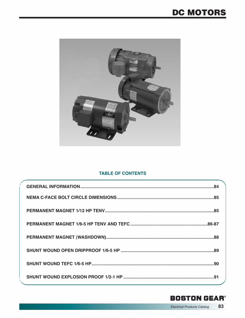
®®
Electrical Products Catalog 83
DC MOTORS
TABLE OF CONTENTS
GENERAL INFORMATION.............................................................................................................84
NEMA C-FACE BOLT CIRCLE DIMENSIONS...............................................................................85
PERMANENT MAGNET 1/12 HP TENV.........................................................................................85
PERMANENT MAGNET 1/6-5 HP TENV AND TEFC ...............................................................86-87
PERMANENT MAGNET (WASHDOWN)........................................................................................88
SHUNT WOUND OPEN DRIPPROOF 1/6-5 HP ............................................................................89
SHUNT WOUND TEFC 1/6-5 HP....................................................................................................90
SHUNT WOUND EXPLOSION PROOF 1/2-1 HP ..........................................................................91

®
84 Electrical Products Catalog
DC MOTORS
SPEED RANGEAll listed Ratiotrol 90 VDC and 180 VDC motors for Bostoncontrollers have been designed to operate continuously at fullrated torque throughout the specified speed range of thecontrol. All shunt wound motors can operate continuously at20:1 speed range and permanent magnet at 50:1 speed range.Full torque operation is possible at even lower speeds if duty isintermittent. In many cases, reduced loads will permitcontinuous operation at speeds as low as 100:1 speed range.
MOUNTINGSeparate listings are shown for NEMA C-face mounted motorsfor use with flange reductors and rigid base mounted motorsfor coupled loads.
AMBIENT TEMPERATURESAll standard motors are rated for continuous full load operationat ambient temperatures not exceeding 40°C (104°F). Theinsulation used varies with motor design; therefore, whenhigher temperatures than normal are expected, please contactthe factory with complete details i.e., maximum temperature,HP, enclosure, mounting, etc.
CATALOG NUMBERING SYSTEMWith few exceptions, noted below, motor catalog numbersindicate voltage HP and enclosure.
V9 SERIES – 1/6 – 1 HP, 90 VDC armature, 50/100 VDC field.V9 16 0 0 — – B| | | | | |A B C D E F
A – Series designation D – MountingB – 16 - 1/6 HP 0 – NEMA C-Face
25 - 1/4 HP 1 – Rigid Base33 - 1/3 HP E – Enclosure*50 - 1/2 HP No letter – Open dripproof75 - 3/4 HP T – TENV
100 - 1 HP TF – TEFCC – 0 - 1750 RPM (Standard) X – Explosion-proof
1 - 1150 RPM F – Manufacturer2 - 2500 RPM B – Baldor3 - 3450 RPM
V18 SERIES – 3/4-5 HP, 180VDC armature, 100/200VDCfield.
V18 10 0 TF –B| | | | |A B C D E
A – Series designation C – MountingB – HP 0 – NEMA C-Face
10 - 1 HP 1 – Rigid Base15 - 1-1/2 HP D – Enclosure*20 - 2 HP No letter – Open dripproof30 - 3 HP T – TENV50 - 5 HP TF – TEFC
X – Explosion-proofE – Manufacturer
B – Baldor
PM MOTORSPM 9 16 AT – B PM 18 100 AT – I
| | | | | | | | | |A B C D E A B C D E
A – PM Series designation D – Enclosure*B – Voltage, armature No letter – Open dripproof
9-90VDC AT, T – TENV18-180VDC ATF, TF – TEFC
C – HP WB – Washdown (BISSC)16 - 1/6 HP 100 - 1 HP E – Manufacturer25 - 1/4 HP 150 - 1-1/2 HP B – Baldor33 - 1/3 HP 200 - 2 HP I – Indiana General50 - 1/2 HP 300 - 3 HP75 - 3/4 HP
OPTIONS AND MODIFICATIONSFrom an economic and delivery standpoint, it is, of course,preferable that standard stock motors be specified for an appli -ca tion. However, many other types of motors and optionalfeatures are available on a special order basis. Some modi -fications are more readily available on fractional HP motorsthan integral HP and vice versa. Among the many options are:Base-Speeds other than 1750 RPM such as 3450, 2500and 1150 RPM.Severe Duty and corrosion-proof enclosures.Explosion-Proof enclosures–specify Class and Group ofhazardous atmosphere.Brakemotors–brakes are AC.Double Shafts, extended shafts, etc.Motor-Mounted Tachometer Generators–for thosemotors not adaptable to standard tachometer packages.See Pages 49 and 50 for stock tachometer generators.
Ratiotrol DC motors have specific characteristics to match the controls with which they operate. Thus, it is not necessary that amotor and control be mated; any stock motor will operate with a stock control of suitable rating within a series.Standard motors have a base speed of 1750 RPM and are stocked in ratings from 1/6 through 5 HP. Operating characteristics,reliability and durability are similar; PM motors do offer advantages such as smaller size, lower weight and the absence of field humon critical applications. In addition, installation is simplified since only two armatures leads need be connected.Service factor for PM and V series motors is 1.0.
*Motor Enclosures described on Page 81.

Boston NEMA KeyGear Frame Max. Max.
Bore Code No. U AK AH AH1 SQ. LG. AJ BF
B4 42CZ .5000 3.000 1-5/16 — 1/8 3/4 3.750 1/4–20.4995 2.997
B5 56C .6250 4.500 2-5/32 — 3/16 1-3/8 5.875 3/8-16.6245 4.49756CZ182C
B7184C .8750 4.500 2-5/32 — 3/16 1-3/8 5.875 3/8–16143TC .8745 4.497145TC213C
B9 215C 1.1250 8.500 — 2-25/32 1/4 1-3/4 7.250 1/2–13182TC 1.1245 8.497184TC254UC
B11 256UC 1.3750 8.500 — 3-17/32 5/16 2-3/8 7.250 1/2–13213TC 1.3745 8.497215TC
B13 254TC 1.6250 8.500 — 3-13/16 3/8 2-7/8 7.250 1/2–13256TC 1.6240 8.497
NEMA C-Face Motor Bolt Circle DimensionsKEY
U
AJ
BF HOLES
AH
AH1
AK
EP08
7A
EP08
8A
6 516
14
1932
6 116
118
303 WOODRUFFKEYWAY
.3125
.3120
(4) 10•32 HOLESTAPPED THRUEQUALLY SPACED
1.3751.373
2 34
3 78
4"
1 34
DIA
EP08
9A
6 316
2 1316 3 1
4
1 38
1316LONG
DEEPFLAT 1
32
.3125
.3120DIA.
(4)
SLOTS
932
12X
REF.
3 78
4"
2 332
Flanged Reductors are designed for use with motors having NEMA “C” face and shaft dimensions as shown. AH and AH1 must not be exceeded.
Permanent MagnetTENV
1/12 Horsepower
ApproximateVolts Catalog Item NEMA Weight
HP Armature Number Code Mounting (Lbs.)
1/12 90 PM908T-B 69825 Special 4
1/12 90 BPM908T-B 64803 Special 4
ORDER BY CATALOG NUMBER OR ITEM CODE
C-FACE MOUNTED
BASE MOUNTED
®
Electrical Products Catalog 85
DC MOTORS

®
86 Electrical Products Catalog
DC MOTORSNEMA C-Face Permanent Magnetw/Removable Bases TENV & TEFC
1/6-5 HP1750RPM
VoltsArma- Catalog Item Bore NEMA
HP ture Number Code Code MTG Encl. C C’ D E F N O P P’
APM916AT-B 19117 B4 42CYZ TENV 9.50 — 3.50 2.44 1.50 1.13 5.88 4.68 —
1/6 90APM916T 59475 B4 42CYZ TENV 8.47 — 3.50 2.44 1.50 1.17 5.75 4.87 —
PM916AT-B 19120 B5 56C TENV 10.31 — 3.50 2.44 1.50 1.94 5.88 4.68 —PM916T 59476 B5 56C TENV 9.19 — 3.50 2.44 1.50 1.90 6.75 4.87 —
APM925AT-B 19118 B4 42CYZ TENV 10.44 — 3.50 2.44 1.50 1.13 5.88 4.68 —
1/4 90APM925T 59477 B4 42CYZ TENV 8.97 — 3.50 2.44 1.50 1.17 5.75 4.87 —
PM925AT-B 19121 B5 56C TENV 11.25 — 3.50 2.44 1.50 1.94 5.88 4.68 —PM925T 59478 B5 56C TENV 9.72 — 3.50 2.44 1.50 1.90 6.75 4.87 —
APM933AT-B 19119 B4 42CYZ TENV 11.38 — 3.50 2.44 1.50 1.13 5.88 4.68 —
1/3 90APM933T 59479 B4 42CYZ TENV 9.47 — 3.50 2.44 1.50 1.17 5.75 4.87 —
PM933AT-B 19122 B5 56C TENV 12.18 — 3.50 2.44 1.50 1.94 5.88 4.68 —PM933T 59480 B5 56C TENV 10.19 — 3.50 2.44 1.50 1.90 6.75 4.87 —
90PM950AT-B 19123 B5 56C TENV 13.94 — 3.50 2.44 1.50 1.94 5.88 4.68 —
1/2PM950TF 59481 B5 56C TEFC — 11.81 3.50 2.44 1.50 1.90 6.75 4.87 5.16
180PM1850TF-B 19186 B5 56C TEFC — 13.75 3.50 2.44 1.50 1.94 6.38 5.81 6.13PM1850TF 59482 B5 56C TEFC — 11.81 3.50 2.44 1.50 1.90 6.75 4.87 5.16
90PM975TF-B 69853 B5 56C TEFC — 13.75 3.50 2.44 1.50 1.94 6.38 5.81 6.13
3/4PM975TF 59483 B5 56C TEFC — 14.31 3.50 2.44 1.50 1.90 6.75 4.87 5.16
180PM1875TF-B 69866 B5 56C TEFC — 13.75 3.50 2.44 1.50 1.94 6.38 5.81 6.13PM1875TF 59484 B5 56C TEFC — 13.81 3.50 2.44 1.50 1.90 6.75 4.87 5.16
PM9100TF-B 69867 B7 56CZ TEFC — 14.68 3.50 2.44 1.50 2.00 6.38 5.81 6.13
90PM9100TF 59485 B7 56CZ TEFC — 16.31 3.50 2.44 1.50 1.90 6.38 5.61 5.88
PM9100TF-5/8-B 50421 B5 56C TEFC — 14.63 3.50 2.44 1.50 1.94 6.38 5.81 6.13
1PM9100TF-5/8 59486 B5 56C TEFC — 15.81 3.50 2.44 1.50 1.90 6.75 5.61 5.88
PM18100TF-B 69869 B7 56CZ TEFC — 14.68 3.50 2.44 1.50 2.00 6.38 5.81 6.13
180PM18100TF 59487 B7 56CZ TEFC — 15.31 3.50 2.44 1.50 1.90 6.75 5.61 5.88
PM18100TF-5/8-B 50424 B5 56C TEFC — 14.63 3.50 2.44 1.50 1.94 6.38 5.81 6.13PM18100TF-5/8 59488 B5 56C TEFC — 14.81 3.50 2.44 1.50 1.90 6.75 5.61 5.88
1-1/2 180PM18150TF-B 69870 B7 56CZ TEFC — 17.19 3.50 2.44 1.50 2.00 6.88 6.50 7.19PM18150TF 59489 B7 143/145TC TEFC — 18.34 3.50 2.75 2.00† 1.96 6.75 6.55 7.16
2 180PM18200TF-B 68783 B7 56CZ TEFC — 18.19 3.50 2.44 1.50 2.00 6.88 6.50 7.19PM18200TF 59490 B7 143/145TC TEFC — 19.34 3.50 2.75 2.00† 1.96 6.75 6.55 7.16
3 180 PM18300TF-B 69411 B9 184TC TEFC — 24.09 4.50 3.75 2.75 2.50 10.00 7.88 8.88
5 180 PM18500TF-B 69412 B9 1810ATC TEFC — 27.59 4.50 3.75 2.75 2.00 10.00 7.88 8.88
†Includes 6 mounting holesAll dimensions in inches. Dimensional information for estimating purposes only.
ORDER BY CATALOG NUMBER OR ITEM CODE
EP
255A
C'
C
AH
N
KEY
AK
UDIA.
BAF
FE E
O
D
XP
AJ
BD
P'
P
.34 WIDESLOTS
(4) BF-UNC-2BTAPPED HOLESEQUALLY SPACEDON AJ DIA. B.C.
AB

Volts U Key Approx.Arma- Catalog Bore NEMA +.0000 Weight
HP ture Number Code MTG -.0005 SQ. Long AH AJ AK BA BD BF XP (Lbs.) AB
APM916AT-B B4 42CYZ .5000 1/8 .75 1.28 3.75 3.00 2.75 4.63 1/4-20 4.56 21 –
1/6 90APM916T B4 42CYZ .5000 1/8 .88 1.31 3.75 3.00 2.69 – 1/4-20 – 19 4.47
PM916AT-B B5 56C .6250 3/16 1.38 2.06 5.88 4.50 2.75 6.50 3/8-16 4.56 21 –PM916T B5 56C .6250 3/16 1.38 2.06 5.88 4.50 2.69 6.50 3/8-16 – 19 4.47
APM925AT-B B4 42CYZ .5000 1/8 .75 1.28 3.75 3.00 2.75 4.63 1/4-20 4.56 22 –
1/4 90APM925T B4 42CYZ .5000 1/8 .88 1.31 3.75 3.00 2.69 – 1/4-20 – 21 4.47
PM925AT-B B5 56C .6250 3/16 1.38 2.06 5.88 4.50 2.75 6.50 3/8-16 4.56 22 –PM925T B5 56C .6250 3/16 1.38 2.06 5.88 4.50 2.69 6.50 3/8-16 – 23 4.47
APM933AT-B B4 42CYZ .5000 1/8 .75 1.28 3.75 3.00 2.75 4.63 1/4-20 4.56 26 –
1/3 90APM933T B4 42CYZ .5000 1/8 .88 1.31 3.75 3.00 2.69 – 1/4-20 – 24 4.47
PM933AT-B B5 56C .6250 3/16 1.38 2.06 5.88 4.50 2.75 6.50 3/8-16 4.56 26 –PM933T B5 56C .6250 3/16 1.38 2.06 5.88 4.50 2.69 6.50 3/8-16 – 23 4.47
1/290
PM950AT-B B5 56C .6250 3/16 1.38 2.06 5.88 4.50 2.75 6.50 3/8-16 4.56 32 –PM950TF B5 56C .6250 3/16 1.38 2.06 5.88 4.50 2.69 6.50 3/8-16 – 26 4.47
180PM1850TF-B B5 56C .6250 3/16 1.38 2.06 5.88 4.50 2.69 6.63 3/8-16 4.00 32 –PM1850TF B5 56C .6250 3/16 1.38 2.06 5.88 4.50 2.69 6.50 3/8-16 – 26 4.47
90PM975TF-B B5 56C .6250 3/16 1.38 2.06 5.88 4.50 2.69 6.63 3/8-16 4.00 39 –
3/4PM975TF B5 56C .6250 3/16 1.38 2.06 5.88 4.50 2.69 6.50 3/8-16 – 37 4.47
180PM1875TF-B B5 56C .6250 3/16 1.38 2.06 5.88 4.50 2.69 6.63 3/8-16 4.00 39 –PM1875TF B5 56C .6250 3/16 1.38 2.06 5.88 4.50 2.69 6.50 3/8-16 – 37 4.47
PM9100TF-B B7 56CZ .8750 3/16 1.38 2.06 5.88 4.50 2.69 6.63 3/8-16 4.00 44 –
90PM9100TF B7 56CZ .8750 3/16 1.38 2.06 5.88 4.50 2.69 6.50 3/8-16 – 47 4.87
PM9100TF-5/8-B B5 56C .6250 3/16 1.38 2.06 5.88 4.50 2.69 6.63 3/8-16 4.00 44 –
1PM9100TF-5/8 B5 56C .6250 3/16 1.38 2.06 5.88 4.50 2.69 6.50 3/8-16 – 47 4.87
PM18100TF-B B7 56CZ .8750 3/16 1.38 2.06 5.88 4.50 2.69 6.63 3/8-16 4.00 44 –
180PM18100TF B7 56CZ .8750 3/16 1.38 2.06 5.88 4.50 2.69 6.50 3/8-16 – 43 4.87
PM18100TF-5/8-B B5 56C .6250 3/16 1.38 2.06 5.88 4.50 2.69 6.63 3/8-16 4.00 44 –PM18100TF-5/8 B5 56C .6250 3/16 1.38 2.06 5.88 4.50 2.69 6.50 3/8-16 – 42 4.87
1-1/2 180PM18150TF-B B7 56CZ .8750 3/16 1.38 2.13 5.88 4.50 2.88 6.63 3/8-16 4.25 73 –PM18150TF B7 143/145TC .8750 3/16 1.38 2.13 5.88 4.50 3.00 – 3/8-16 – 76 5.31
2 180PM18200TF-B B7 56CZ .8750 3/16 1.38 2.13 5.88 4.50 2.88 6.63 3/8-16 4.25 75 –PM18200TF B7 143/145TC .8750 3/16 1.38 2.13 5.88 4.50 3.00 – 3/8-16 – 83 5.31
3 180 PM18300TF-B B9 184TC 1.1250 1/4 1.75 2.63 7.25 8.50 2.88 9.00 1/2-13 6.06** 116 –
5 180 PM18500TF-B B9 1810ATC 1.1250 1/4 2.00 2.13 7.25 8.50 2.88 9.00 1/2-13 6.06** 157 –
** The conduit box is located 90 degrees to the base*** .41 wide slots on 3 & 5 HP motorsAll dimensions in inches. Dimensional information for estimating purposes only.
ORDER BY CATALOG NUMBER OR ITEM CODE
EP
255A
C'
C
AH
N
KEY
AK
UDIA.
BAF
FE E
O
D
XP
AJ
BD
P'
P
.34 WIDESLOTS
(4) BF-UNC-2BTAPPED HOLESEQUALLY SPACEDON AJ DIA. B.C.
AB
®
Electrical Products Catalog 87
DC MOTORSNEMA C-Face Permanent Magnetw/Removable Bases TENV & TEFC
1/6-5 HP1750 RPM(Continued)

®
88 Electrical Products Catalog
DC MOTORSNEMA C-Face Permanent MagnetWashdown TENV/TEFC
1/4-1 1/2 Horsepower1750 RPM
VoltsArma- Catalog Item Bore NEMA Encl.
HP ture Number Code Code Mtg. C C’1/4 90 PM925T-WD 59354 B5 56C TENV 10.69 –1/3 90 PM933T-WD 59355 B5 56C TENV 11.69 –
1/290 PM950T-WD 59356 B5 56C TENV 13.69 –180 PM1850T-WD 59357 B5 56C TENV 13.69 –
3/490 PM975T-WD 59364 B5 56C TENV 15.69 –180 PM1875T-WD 59365 B5 56C TENV 15.69 –
190 PM9100TF-5/8-WD 59366 B5 56C TEFC – 15.81180 PM18100TF-5/8-WD 59367 B5 56C TEFC – 14.81
1-1/2 180 PM18150TF-5/8-WD 59368 B5 56C TEFC – 16.81
ORDER BY CATALOG NUMBER OR ITEM CODE
Boston’s Permanent Magnet Washdown Motors are specifically designed for usewhere dust, dirt and moisture are present in industrial and washdown environments.These motors retard the entrance of water during cleaning operations and releaseany water that does enter the motor. Extra protection for the motor’s interior preventsrust and corrosion build-up and drains release trapped moisture to insure a longer lifethan possible with a standard motor. The motors are constructed using stainless steelshafts, hardware and nameplates, sealed ball bearings and forsheda seals to preventwater leakage into the motor.
All dimensions in inches. Dimensional information for estimating purposes only.
6.50

®
Electrical Products Catalog 89
DC MOTORSNEMA C-FACE Shunt Wound With Removable Bases Open Dripproof
1/6-5 HP1750 RPM
U Key Approx.Catalog Item +.0000 Weight
HP Number Code -.0005 Sq. Long AB AH AJ AK BA BD BF (lbs.)1/6 V91600-B 66666 .6250 3/16 1.38 4.50 2.06 5.88 4.500 2.69 6.63 3/8-16 221/4 V92500-B 66669 .6250 3/16 1.38 4.50 2.06 5.88 4.500 2.69 6.63 3/8-16 221/3 V93300-B 66672 .6250 3/16 1.38 4.50 2.06 5.88 4.500 2.69 6.63 3/8-16 231/2 V95000-B 66675 .6250 3/16 1.38 4.50 2.06 5.88 4.500 2.69 6.63 3/8-16 28
3/4V97500-B 66678 .6250 3/16 1.38 4.50 2.06 5.88 4.500 2.69 6.63 3/8-16 34V18750-B 66681 .6250 3/16 1.38 4.50 2.06 5.88 4.500 2.69 6.63 3/8-16 34V9100-B 66897 .8750 3/16 1.38 5.25 2.13 5.88 4.500 2.69 6.63 3/8-16 611V18100-B 66684 .8750 3/16 1.38 5.25 2.13 5.88 4.500 2.69 6.63 3/8-16 61
1-1/2 V18150A-B 66690 .8750 3/16 1.38 5.88 2.13 5.88 4.500 2.88 7.88 3/8-16 872 V18200A-B 66696 .8750 3/16 1.38 5.88 2.13 5.88 4.500 2.88 7.88 3/8-16 1053 18300-B 66702 1.1250 1/4 1.75 7.38 3.00 7.25 8.500 3.50 9.00 1/2-13 1555 18500A-B 66790 1.3750 5/16 2.38 8.88 3.50 7.25 8.500 4.50 9.63 1/2-13 290
VoltsArma- Volts Catalog Item Bore NEMA
HP ture Field Number Code Code Mtg C D E F H* N O P1/6 90 50/100 V91600-B 66666 B5 56C 11.94 3.50 2.44 1.50 .34(S) 1.94 6.38 5.681/4 90 50/100 V92500-B 66669 B5 56C 11.94 3.50 2.44 1.50 .34(S) 1.94 6.38 5.681/3 90 50/100 V93300-B 66672 B5 56C 11.94 3.50 2.44 1.50 .34(S) 1.94 6.38 5.681/2 90 50/100 V95000-B 66675 B5 56C 12.94 3.50 2.44 1.50 .34(S) 1.94 6.38 5.68
90 50/100 V97500-B 66678 B5 56C 13.56 3.50 2.44 1.50 .34(S) 1.94 6.38 5.683/4180 100/200 V18750-B 66681 B5 56C 13.56 3.50 2.44 1.50 .34(S) 1.94 6.38 5.6890 50/100 V9100-B 66897 B5 56CZ 15.06 3.50 2.44 1.50 .34(S) 2.00 6.88 6.501180 100/200 V18100A-B 66684 B7 56CZ 15.06 3.50 2.44 1.50 .34(S) 2.00 6.88 6.50
1-1/2 180 100/200 V18150A-B 66690 B7 184C 15.06 4.50 3.75 2.75 .41 2.00 8.44 7.882 180 100/200 V18200A-B 66696 B7 184C 18.38 4.50 3.75 2.75 .41 2.00 8.44 7.883 180 100/200 18300-B 66702 B9 215C 20.94 5.25 4.25 3.50 .41 2.75 9.94 9.385 180 100/200 18500A-B 66790 B11 256UC 23.38 6.25 5.00 5.00 .53 3.25 11.94 11.38
ORDER BY CATALOG NUMBER OR ITEM CODE
*(S) Slotted (Dim is Width)All dimensions in inches. Dimensional information for estimating purposes only.
EP
256A
KEY
AKDIA.
UDIA.
F
F
N
BA
AH
AB
BD
O
D
E(4) H DIA.HOLES
(4) BF UNC-2BTAPPED HOLESEQUALLY SPACEDON “AJ” DIA. B.C.45°
P
C
E

®
90 Electrical Products Catalog
DC MOTORSNEMA C-FACE Shunt Wound With Removable Bases TEFC
1/6-5 HP1750 RPM
VoltsArma- Volts Catalog Item Bore NEMA
HP ture Field Number Code Code Mtg C’ D E F H* N O P’
1/6 90 50/100 V91600TF-B 66741 B5 56C 12.56 3.50 2.44 1.50 .34(S) 1.94 6.38 6.13
1/4 90 50/100 V92500TF-B 66744 B5 56C 13.25 3.50 2.44 1.50 .34(S) 1.94 6.38 6.13
1/3 90 50/100 V93300TF-B 66747 B5 56C 13.25 3.50 2.44 1.50 .34(S) 1.94 6.38 6.13
1/2 90 50/100 V95000TF-B 66750 B5 56C 14.25 3.50 2.44 1.50 .34(S) 1.94 6.38 6.13
3/490 50/100 V97500TF-B 66752 B5 56C 14.75 3.50 2.44 1.50 .34(S) 1.94 6.38 6.13
180 100/200 V18750TF-B 66755 B5 56C 14.75 3.50 2.44 1.50 .34(S) 1.94 6.38 6.13
90 50/100 V9100BTF-B 66901 B7 56CZ 15.50 3.50 2.44 1.50 .34(S) 2.00 6.88 7.181
180 100/200 V18100BTF-B 66757 B7 56CZ 16.24 3.50 2.44 1.50 .34(S) 2.00 6.88 7.18V18100ATF-B 66761 B7 182C 15.56 4.50 3.75 2.75 .41 2.00 8.44 8.50
1-1/2 180 100/200 V18150ATF-B 66767 B7 184C 17.31 4.50 3.75 2.75 .41 2.00 8.44 8.50
2 180 100/200 V18200ATF-B 66773 B7 184C 18.56 4.50 3.75 2.75 .41 2.00 8.44 8.50
3 180 100/200 18300ATF-B 66778 B9 215C 21.18 5.25 4.25 3.50 .41 2.75 9.94 10.18
5 180 100/200 18500ATF-B 66791 B11 256UC 24.38 6.25 5.00 5.00 .53 3.50 11.94 12.38
ORDER BY CATALOG NUMBER OR ITEM CODE
*(S) Slotted (Dim is Width)All dimensions in inches. Dimensional information for estimatingpurposes only.
U Key Approx.Item +.0000 Weight
HP Catalog Number Code -.0005 Sq. Long AB AH AJ AK BA BD BF XP (lbs.)
1/6 V91600TF-B 66741 .6250 3/16 1.38 — 2.06 5.88 4.500 2.69 6.63 3/8-16 4.00 22
1/4 V92500TF-B 66744 .6250 3/16 1.38 — 2.06 5.88 4.500 2.69 6.63 3/8-16 4.00 22
1/3 V93300TF-B 66747 .6250 3/16 1.38 — 2.06 5.88 4.500 2.69 6.63 3/8-16 4.00 23
1/2 V95000TF-B 66750 .6250 3/16 1.38 — 2.06 5.88 4.500 2.69 6.63 3/8-16 4.00 28
3/4V97500TF-B 66752 .6250 3/16 1.38 — 2.06 5.88 4.500 2.69 6.63 3/8-16 4.00 36
V18750TF-B 66755 .6250 3/16 1.38 — 2.06 5.88 4.500 2.69 6.63 3/8-16 4.00 34
V9100BTF-B 66901 .8750 3/16 1.38 — 2.13 5.88 4.500 2.69 6.63 3/8-16 4.25 61
1 V18100BTF-B 66757 .8750 3/16 1.38 5.25 2.13 5.88 4.500 2.75 6.63 3/8-16 — 61V18100ATF-B 66761 .8750 3/16 1.38 6.00 2.13 5.88 4.500 3.00 6.50 3/8-16 — 81
1-1/2 V18150ATF-B 66767 .8750 3/16 1.38 6.00` 2.13 5.88 4.500 3.00 6.50 3/8-16 — 90
2 V18200ATF-B 66773 .8750 3/16 1.38 6.00 2.13 5.88 4.500 3.00 6.50 3/8-16 — 105
3 18300ATF-B 66778 1.1250 1/4 2.00 7.38 3.00 7.25 8.500 3.50 9.00 1/2- 13 — 167
5 18500ATF-B 66791 1.3750 5/16 2.38 9.06 3.75 7.25 8.500 4.50 9.63 1/2-13 — 306
EP
092A
KEY
AKDIA.
UDIA.
F
F
N
AH
AB
BD
O
D
E(4) H DIA.HOLES
(4) BF UNC-2BTAPPED HOLESEQUALLY SPACEDON “AJ” DIA. B.C.45°
P'
E
C'
BA
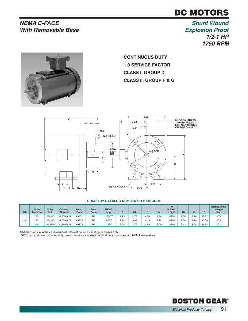
CONTINUOUS DUTY1.0 SERVICE FACTORCLASS I, GROUP DCLASS II, GROUP F & G
EP
DC
6A
KEY
316
SQ.X1.38LG.
4.5004.497DIA.
U
C
F
F
N
BA
AH7.38
6.50
O
D
3.753.75(4) .41 HOLES
(4) 3/8-16 UNC-2BTAPPED HOLESEQUALLY SPACEDON 5-7/8 DIA. B.C.
6 58 REF
45°
All dimensions in inches. Dimensional information for estimating purposes only.*56C Shaft and face mounting only, base mounting and shaft height differs from standard NEMA dimensions.
U ApproximateVolts Volts Catalog Item Bore NEMA +.0000 Weight
HP Armature Field Number Code Code Mtg* F BA D N -.0005 AH O C (lbs.)1/2 90 50/100 V95000X-B 69871 B5 182CZ 2.25 2.75 4.50 1.94 .6250 2.06 8.44 18.62 1033/4 90 50/100 V97500X-B 69872 B5 66CZ 2.50 3.06 4.13 1.94 .6250 2.06 7.94 15.56 1051 180 100/200 V18100X-B 69873 B7 182C 2.75 2.75 4.50 2.00 .8750 2.13 8.44 18.68 103
ORDER BY CATALOG NUMBER OR ITEM CODE
®
Electrical Products Catalog 91
DC MOTORSNEMA C-FACE Shunt Wound With Removable Base Explosion Proof
1/2-1 HP1750 RPM

®
92 Electrical Products Catalog
NOTES

®
Electrical Products Catalog 93
AC MOTORS
®
GENERAL INFORMATION.............................................................................................................94
NEMA C-FACE DIMENSIONS........................................................................................................94
OPEN DRIPPROOF...................................................................................................................95-96
TENV...............................................................................................................................................97
TEFC........................................................................................................................................98-102
WASHDOWN/BISSC ....................................................................................................................103
BRAKE MOTORS..................................................................................................................104-105
EXPLOSION PROOF....................................................................................................................106
RIGID BASE..................................................................................................................................107
INVERTER DUTY ..................................................................................................................108-109
TABLE OF CONTENTS

®
AC MOTORS
®
94 Electrical Products Catalog
Boston Gear AC motors are general purpose motors selectedfor use with Boston Gear Reductors and Flanged Reductorsand are suitable for all common industrial applications.
HORSEPOWER — Motor’s listed range from 1/20 to 75 HP.Larger HP motors can be supplied.
VOLTAGES — All motors listed are for 60 Hz (cycle) power;fractional HP motors are also stocked in 50 Hz single phaseratings.
SINGLE-PHASE motors are split phase 1/20 HP through 1/6HP. Some 1/6 HP motors and all 1/4 HP motors and largerare capacitor start. Standard 60 Hz voltages are 115V, 230Vor 115/230V. 50 Hz voltages are 110/220. NOTE: 50 Hzmotors have a speed of 1425 RPM, nominal. Single phase 60Hz motors cannot be used on 50 Hz power.
POLYPHASE motors are all NEMA design B inductionmotors. Standard 60 Hz voltages are 208-230/460 and 575V.50 Hz Voltage are 220/380/440. NOTE: 50Hz motors have aspeed of 1425 RPM nominal.
MOUNTING — Separate listings are shown for NEMA C-facemounted motors for use with flange reductors and rigid basemounted motors for coupled loads.
SERVICE FACTORS indicate the allowable overload on amotor. The service factors vary from motor to motor. Pleaseconsult factory for the service factor on any particular motor.ALLOWABLE STARTS AND STOPS—based on no externalinertia and each start from a standstill:Three phase motors ............................up to 20 times per min.Single phase–split phase motors.........up to 20 times per hourSingle phase–capacitor motors ...........up to 30 times per hour
BOSTON GEAR MOTOR CATALOG NUMBERS consistsgenerally of two or more letters denoting horsepower, voltage,enclosure and mounting for motors 1/6 HP and larger.
Prefix H.P. Voltage Enclosure Suffix ManufacturerA-Small Frame A - 1/20 R 115/230-1-60 No letter-Dripproof B-Brake B-BalderB-Rigid Base AA - 1/12 S 115-1-60 T-TENV 35-3450 RPM W-WEG
B - 1/8 T 230-1-60 TF-TEFC 11-1150 RPMC - 1/6 U 230/460-3-60 X-Explosion ProofD - 1/4 Y 575-3-60 WB-Washdown BISSCE - 1/3 R5 110/220-1-50 BC-TEBCF - 1/2 S5 110-1-50G - 3/4 T5 230-1-50H - 1 U5 220/380/440-3-50
J - 1-1/2K - 2L - 3M - 5
N - 7-1/2P - 10R - 15S - 20T - 25U - 30V - 40W - 50X - 60Y - 75
Z - 100
NOTE: A dash followed by a letter indicates the motor manufacturereg -”-B” - Baldor or “W”- -WEG Example - FUTF-B 1/2 HP, 230/460-3 -60, TEFC, Baldor.
REVERSING—All listed motors are reversible with standardmotor reversing switches or suitable manual or magneticrevers ing starters. Single phase motors must stop beforerevers ing; polyphase may be instantly reversed by reversingany two of the three incoming power leads with a suitablestarter.AMBIENT TEMPERATURES — All standard motors are ratedfor continuous full load operation at ambient temperatures notexceed ing 40°C (104°F). The insulation used varies with motordesign; therefore, when higher temperatures than normal areexpected, please contact the factory with complete details i.e.,maximum temperature, HP, enclosure, mounting, etc.
Boston NEMA KeyGear Frame Max. Max.
Bore Code No. U AK AH AH’ Sq. Lg. AJ BF
B4 42CZ .5000 3.000 1-5/16 — 1/8 3/4 3.75 1/4-20.4995 2.997
B5 56C .6250 4.500 2-5/32 — 3/16 1-3/8 5.88 3/8-16.6245 4.497182C
B7184C .8750 4.500 2-5/32 — 3/16 1-3/8 5.88 3/8-16143TC .8745 4.497145T C213C
B9215C 1.1250 8.500 — 2-25/32 1/4 1-3/4 7.25 1/2-13182TC 1.1245 8.497184TC254UC
B11256UC 1.3750 8.500 — 3-17/32 5/16 2-3/8 7.25 1/2-13213TC 1.3745 8.497215TC
B13 254TC 1.6250 8.500 — 3-13/16 3/8 2-7/8 7.25 1/2-13256TC 1.6240 8.497
NEMA C-Face Bolt Circle Dimensions
KEY
U
AJ
BF HOLES
AH
AH1
AK
EP08
7A
NOTE: Motor enclosures description on page 81.

®
AC MOTORS
®
Electrical Products Catalog 95
110/220 VAC 1ø 50 Hz Open Dripproof115 VAC 1ø 60 Hz NEMA C-Face115/230 VAC 1ø 60 Hz Single Phase
1/4–1-1/2 Horsepower
ORDER BY CATALOG NUMBER OR ITEM CODE
All Dimensions in Inches. Dimensional Information for Estimating Purposes OnlyNOTE: #302.5 Woodruff Key (3/32 wide)
EP07
7A
C
KEY
N
P
AH
U
AB
BD
(4) BF UNC-2BTAPPED HOLES EQUALLYSPACED ON AJ DIA. B.C.
45°
XO
AK
F.L.A. U Key@Max NEMA Bore Catalog Item +.0000 Wt.
HP RPM Volts Mtg Code Number Code C N P -.0005 Sq. Long AB AH AJ AK BD BF X0 Lbs
110/220 VAC 1ø 50 Hz
1/4 1425 2.8 56C B5 DR5-B 66854 10.25 1.94 5.69 0.625 3/16 1.38 4.75 2.06 5.88 4.50 5.87 3/8-16 1.54 221/3 1425 3.2 56C B5 ER5-B 66866 10.69 1.94 5.69 0.625 3/16 1.38 4.75 2.06 5.88 4.50 5.87 3/8-16 1.54 251/2 1425 4.4 56C B5 FR5-B 66872 11.56 1.94 5.69 0.625 3/16 1.38 4.75 2.06 5.88 4.50 5.87 3/8-16 1.54 273/4 1425 6.5 56C B5 GR5-B 66878 11.06 1.94 6.63 0.625 3/16 1.38 5.75 2.06 5.88 4.50 6.50 3/8-16 2.25 35
115 VAC 1ø 60 Hz
1/20 1725 1.35 SP SPL AST-B 65403 8.98 0.93 3.86 0.313 See Note — 1.18 1.75 1.38 4.64 10/32 — 101/12 1725 2.0 SP SPL AAST-B 65402 8.98 0.93 3.86 0.313 See Note — 1.18 1.75 1.38 4.64 10/32 — 101/4 1725 2.7 56C B5 DS 63316 8.88 1.94 5.61 0.625 3/16 1.38 — 2.06 5.88 4.50 5.61 3/8-16 1.94 161/4 1725 5.0 56C B5 DS-B 66112 10.25 1.94 5.69 0.625 3/16 1.38 4.50 2.06 5.88 4.50 5.81 3/8-16 1.54 221/4 1725 5.3 56C B5 DS-W 65220 9.65 1.91 5.71 0.625 3/16 1.10 — 2.06 5.88 4.50 5.75 3/8-16 — 19
115/230 VAC 1ø 60 Hz
1/6 1725 2.0 56C B5 CR-W 65221 9.65 1.91 5.71 0.625 3/16 1.10 — 2.06 5.88 4.50 5.75 3/8-16 — 181/6 1725 1.9 56C B5 CR-B 85773 10.09 1.93 — 0.625 3/16 1.38 4.41 2.06 5.88 4.50 5.87 3/8-16 1.41 181/4 1725 2.7 56C B5 DR 63315 8.88 1.94 5.61 0.625 3/16 1.38 — 2.06 5.88 4.50 5.61 3/8-20 1.94 161/4 1725 2.7 56C B5 DR-W 65222 9.65 1.91 5.71 0.625 3/16 1.10 — 2.06 5.88 4.50 5.75 3/8-16 — 191/4 1725 2.5 56C B5 DR-B 66109 10.25 1.94 5.69 0.625 3/16 1.38 4.88 2.06 5.88 4.50 5.81 3/8-16 1.54 221/3 1725 3.1 56C B5 ER 63317 9.38 1.94 5.61 0.625 3/16 1.38 — 2.06 5.88 4.50 5.61 3/8-20 1.94 191/3 1725 3.1 56C B5 ER-W 65223 10.55 1.91 5.71 0.625 3/16 1.10 — 2.06 5.88 4.50 5.45 3/8-16 — 221/3 1725 3.0 56C B5 ER-B 66121 10.25 1.94 5.69 0.625 3/16 1.38 4.88 2.06 5.88 4.50 5.81 3/8-16 1.54 251/2 1725 4.4 56C B5 FR 63318 9.88 1.94 5,61 0.625 3/16 1.38 — 2.06 5.88 4.50 5.81 3/8-20 1.94 191/2 1725 4.4 56C B5 FR-W 65224 10.55 1.91 5.71 0.625 3/16 1.10 — 2.06 5.88 4.50 5.75 3/8-16 — 241/2 1725 4.2 56C B5 FR-B 66130 11.56 1.94 5.69 0.625 3/16 1.38 4.75 2.06 5.88 4.50 5.87 3/8-16 1.54 273/4 1725 5.4 56C B5 GR 63319 10.88 1.94 5.61 0.625 3/16 1.38 — 2.06 5.88 4.50 6.50 3/8-16 1.94 263/4 1725 5.6 56C B5 GR-B 66139 11.56 1.94 6.63 0.625 3/16 1.38 5.88 2.06 5.88 4.50 6.50 3/8-16 2.25 341 1725 6.7 56C B5 HR-5/8-B 19183 12.24 1.94 6.63 0.625 3/16 1.38 5.75 2.06 5.88 4.50 6.50 3/8-16 2.18 351 1725 6.5 143TC B7 HR-B 66145 12.13 1.94 6.63 0.875 3/16 1.38 5.75 2.13 5.88 4.50 6.50 3/8-16 2.25 351-1/2 1725 9.0 145TC B7 JR-B 66154 12.13 1.94 6.63 0.875 3/16 1.38 5.75 2.13 5.88 4.50 6.50 3/8-16 2.25 41

®
AC MOTORS
®
96 Electrical Products Catalog
EP07
7B
C
KEY
N
P
AH
U
AB
BD
(4) BF UNC-2BTAPPED HOLES EQUALLYSPACED ON AJ DIA. B.C.
45°
AK
F.L.A. U Key@Max NEMA Bore Catalog Item +.0000 Wt.
HP RPM Volt Mtg Code Number Code C N P -.0005 Sq. Long AB AH AJ AK BD BF Lbs
208 – 230/460 VAC 3ø 60 Hz
1/6 1725 0.45 56C B5 CU-B 85774 10.10 1.93 — 0.625 3/16 1.38 4.41 2.06 5.88 4.50 5.87 3/8-16 191/6 1725 0.55 56C B5 CU-W 65237 10.32 1.91 6.50 0.625 3/16 1.10 — 2.06 5.88 4.50 6.54 3/8-16 191/4 1725 0.65 56C B5 DU 63531 9.38 1.94 5.61 0.625 3/16 1.38 — 2.06 5.88 4.50 5.61 3/8-16 161/4 1725 0.65 56C B5 DU-W 65238 10.32 1.91 9.50 0.625 3/16 1.10 — 2.06 5.88 4.50 6.54 3/8-16 191/4 1725 0.65 56C B5 DU-B 66115 10.25 1.94 5.69 0.625 3/16 1.38 4.88 2.06 5.88 4.50 5.88 3/8-16 181/3 1725 0.8 56C B5 EU 63532 9.38 1.94 5.61 0.625 3/16 1.38 — 2.06 5.88 4.50 5.61 3/8-16 181/3 1725 0.8 56C B5 EU-W 65239 10.32 1.91 6.50 0.625 3/16 1.10 — 2.06 5.88 4.50 6.54 3/8-16 191/3 1725 0.8 56C B5 EU-B 66124 10.25 1.94 5.69 0.625 3/16 1.38 4.88 2.06 5.88 4.50 5.88 3/8-16 211/2 1725 1.0 56C B5 FU 63533 9.88 1.94 5.61 0.625 3/16 1.38 — 2.06 5.88 4.50 5.61 3/8-16 201/2 1725 1.0 56C B5 FU-W 65241 10.32 1.91 6.50 0.625 3/16 1.10 — 2.06 5.88 4.50 6.54 3/8-16 201/2 1725 1.0 56C B5 FU-B 66133 10.31 1.94 5.69 0.625 3/16 1.38 4.75 2.06 5.88 4.50 5.88 3/8-16 223/4 1725 1.4 56C B5 GU 63536 10.88 1.94 5.61 0.625 3/16 1.38 — 2.06 5.88 4.50 5.61 3/8-16 223/4 1725 1.4 56C B5 GU-W 65243 11.10 1.91 6.50 0.625 3/16 1.10 — 2.06 5.88 4.50 6.54 3/8-16 243/4 1725 1.5 56C B5 GU-B 66142 11.56 1.94 5.69 0.625 3/16 1.38 4.75 2.06 5.88 4.50 5.88 3/8-16 261 1725 1.7 56C B5 HU-5/8 63537 10.88 1.94 6.53 0.625 3/16 1.38 — 2.06 5.88 4.50 5.88 3/8-16 311 1725 1.7 56C B5 HU-5/8-W 65246 11.10 1.91 6.50 0.625 3/16 1.10 — 2.06 5.88 4.50 6.54 3/8-16 261 1725 1.7 56C B5 HU-5/8-B 50427 11.06 1.94 6.63 0.625 3/16 1.38 5.63 2.06 5.88 4.50 6.50 3/8-16 331 1725 1.7 56C B5 HU 63538 10.88 1.94 6.53 0.875 3/16 1.38 5.09 2.06 5.88 4.50 5.88 3/8-16 311 1725 1.7 143TC B7 HU-B 66148 11.13 2.00 6.63 0.875 3/16 1.38 5.63 2.13 5.88 4.50 6.50 3/8-16 33
1-1/2 1725 2.3 145TC B7 JU 63539 11.38 1.94 6.53 0.875 3/16 1.38 5.09 2.06 5.88 4.50 5.88 3/8-16 351-1/2 1725 2.4 145TC B7 JU-B 66157 11.13 2.00 6.63 0.875 3/16 1.38 5.63 2.13 5.88 4.50 6.50 3/8-16 342 1725 3.1 145TC B7 KU 63540 11.38 1.94 6.53 0.875 3/16 1.38 5.09 2.06 5.88 4.50 5.88 3/8-16 372 1725 3.2 145TC B7 KU-B 66163 12.13 2.00 6.63 0.875 3/16 1.38 5.63 2.13 5.88 4.50 6.50 3/8-16 373 1725 4.4 182TC B9 LU 63542 12.63 2.63 8.46 1.125 1/4 1.75 6.30 2.89 7.25 8.50 8.88 1/2-13 653 1725 4.3 182TC B9 LU-B 66166 13.63 2.63 7.88 1.125 1/4 1.75 5.88 2.89 7.25 8.50 9.00 1/2-13 665 1725 7.2 182TC B9 MU 63543 13.13 2.63 8.46 1.125 1/4 1.75 6.30 2.89 7.25 8.50 8.88 1/2-13 625 1725 7.0 184TC B9 MU-B 66170 15.00 2.63 7.88 1.125 1/4 1.75 5.88 2.89 7.25 8.50 9.00 1/2-13 80
7-1/2 1725 11.0 213TC B11 NU-B 66174 17.06 3.13 9.58 1.375 5/16 2.38 7.38 3.38 7.25 8.50 9.00 1/2-13 11410 1725 14.0 215TC B11 PU-B 66176 17.06 3.13 9.96 1.375 5/16 2.38 7.38 3.38 7.25 8.50 9.00 1/2-13 11815 1760 19.9 254TC B13 RU-B 66180 20.00 3.75 11.50 1.625 3/8 2.88 8.94 4.00 7.25 8.50 9.13 1/2-13 22020 1760 26.0 256TC B13 SU-B 66184 21.50 3.75 11.50 1.625 3/8 2.88 8.94 4.00 7.25 8.50 9.13 1/2-13 261
208-230/460 VAC 3ø 60 Hz Open DripproofNEMA C-FaceThree Phase
1/6 – 20 Horsepower
ORDER BY CATALOG NUMBER OR ITEM CODE
All dimensions in inches. Dimensional information for estimating purposes only.

®
AC MOTORS
®
Electrical Products Catalog 97
EP07
8A
C
KEY
N
P
AH
U
AB
BD
(4) BF UNC-2BTAPPED HOLES EQUALLYSPACED ON AJ DIA. B.C.
45°
XO
AK
F.L.A. U Key@ Max NEMA Bore Catalog Item +.0000 Wt.
HP RPM Volt Mtg. Code Number Code C N P -.0005 Sq. Long AB AH AJ AK BD BF XO Lbs.
115/230 VAC 1ø 60 Hz
1/6 1725 2.1 56C B5 CRT-B 85775 10.25 1.94 — 0.625 3/16 1.38 4.90 2.06 5.88 4.50 5.81 3/8-16 1.50 231/6 1725 1.7 42CZ B4 ACRT-W 65320 8.29 1.10 — 0.500 1/8 0.98 4.23 1.26 3.75 3.00 4.80 1/4-20 — 14.11/4 1725 2.4 56C B5 DRT 63544 9.94 1.94 6.53 0.625 3/16 1.38 — 2.06 5.88 4.50 5.88 3/8-16 1.97 271/4 1725 2.7 42CZ B4 ADRT-W 65325 9.67 1.10 — 0.500 1/8 0.98 4.23 1.26 3.75 3.00 4.80 1/4-20 — 18.31/3 1725 2.9 56C B5 ERT 63732 9.94 1.94 6.53 0.625 3/16 1.38 — 2.06 5.88 4.50 5.88 3/8-16 1.97 291/3 1725 3.8 42CZ B4 AERT-W 65346 9.43 1.10 — 0.500 1/8 0.98 4.704 1.26 3.75 3.00 5.75 1/4-20 — 18.3
208 – 230/460 VAC 3ø 60 Hz
1/6 1725 0.6 42CZ B4 ACUT-B 69728 8.52 1.14 — 0.500 1/8 0.88 4.03 1.26 3.75 3.00 4.62 1/4-20 — 171/6 1725 0.4 56C B5 CUT-B 85776 10.25 1.94 5.68 0.625 3/16 1.38 4.51 2.06 5.88 4.50 5.81 3/8-16 — 191/6 1725 0.5 42CZ B4 ACUT-W 65368 7.89 1.10 — 0.500 1/8 0.98 4.65 1.26 3.75 3.00 4.80 1/4-20 — 171/4 1725 0.6 56C B5 DUT 63801 9.44 1.94 5.61 0.625 3/16 1.38 — 2.06 5.88 4.50 5.61 3/8-16 — 161/4 1725 0.6 42CZ B4 ADUT-W 65374 8.65 1.10 — 0.500 1/8 0.98 4.65 1.26 3.75 3.00 4.80 1/4-20 — 171/3 1725 0.65 56C B5 EUT 63952 9.44 1.94 6.53 0.625 3/16 1.38 — 2.06 5.88 4.50 5.88 3/8-16 — 201/3 1725 0.7 42CZ B4 AEUT-W 65381 8.65 1.10 — 0.500 1/8 0.98 4.65 1.26 3.75 3.00 4.80 1/4-20 — 181/2 1725 1.0 56C B5 FUT 63959 10.44 1.94 6.53 0.625 3/16 1.38 — 2.06 5.88 4.50 5.88 3/8-16 — 25
115/230 1ø 60 Hz TENV208 – 230/460 3ø 60 Hz NEMA C-Face
Single and Three Phase1/6 – 1/2 Horsepower
1725 RPM
ORDER BY CATALOG NUMBER OR ITEM CODE
All dimensions in inches. Dimensional information for estimating purposes only.
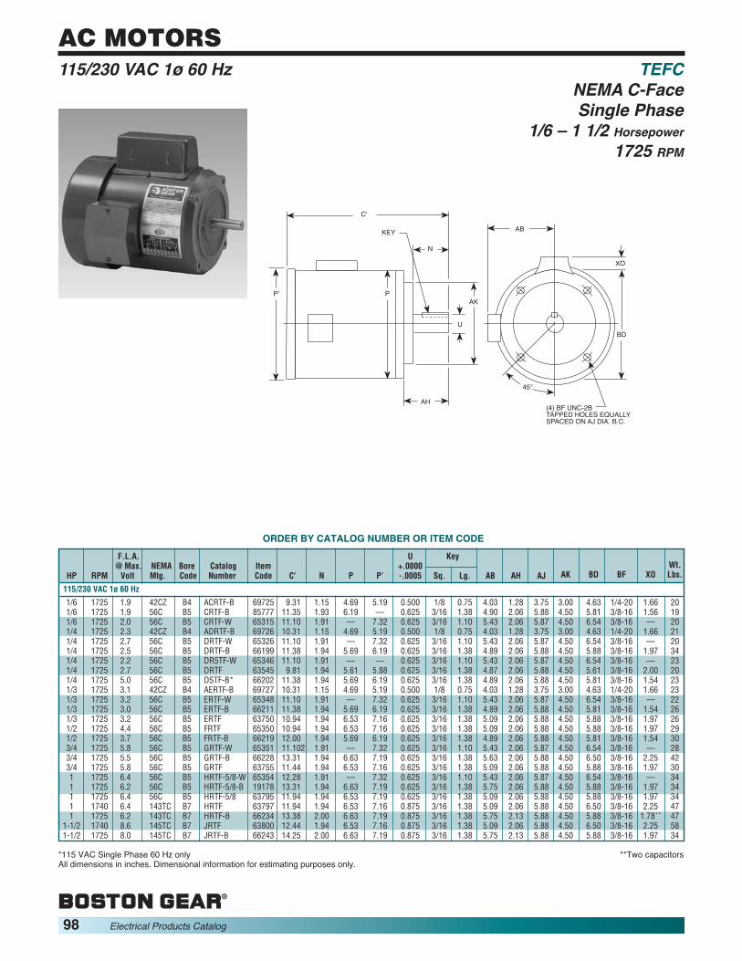
®
AC MOTORS
®
98 Electrical Products Catalog
F.L.A. U Key@ Max. NEMA Bore Catalog Item +.0000
HP RPM Volt Mtg. Code Number Code C′′ N P P’ -.0005 Sq. Lg. AB AH AJ
115/230 VAC 1ø 60 Hz
1/6 1725 1.9 42CZ B4 ACRTF-B 69725 9.31 1.15 4.69 5.19 0.500 1/8 0.75 4.03 1.28 3.751/6 1725 1.9 56C B5 CRTF-B 85777 11.35 1.93 6.19 — 0.625 3/16 1.38 4.90 2.06 5.881/6 1725 2.0 56C B5 CRTF-W 65315 11.10 1.91 — 7.32 0.625 3/16 1.10 5.43 2.06 5.871/4 1725 2.3 42CZ B4 ADRTF-B 69726 10.31 1.15 4.69 5.19 0.500 1/8 0.75 4.03 1.28 3.751/4 1725 2.7 56C B5 DRTF-W 65326 11.10 1.91 — 7.32 0.625 3/16 1.10 5.43 2.06 5.871/4 1725 2.5 56C B5 DRTF-B 66199 11.38 1.94 5.69 6.19 0.625 3/16 1.38 4.89 2.06 5.881/4 1725 2.2 56C B5 DR5TF-W 65346 11.10 1.91 — — 0.625 3/16 1.10 5.43 2.06 5.871/4 1725 2.7 56C B5 DRTF 63545 9.81 1.94 5.61 5.88 0.625 3/16 1.38 4.87 2.06 5.881/4 1725 5.0 56C B5 DSTF-B* 66202 11.38 1.94 5.69 6.19 0.625 3/16 1.38 4.89 2.06 5.881/3 1725 3.1 42CZ B4 AERTF-B 69727 10.31 1.15 4.69 5.19 0.500 1/8 0.75 4.03 1.28 3.751/3 1725 3.2 56C B5 ERTF-W 65348 11.10 1.91 — 7.32 0.625 3/16 1.10 5.43 2.06 5.871/3 1725 3.0 56C B5 ERTF-B 66211 11.38 1.94 5.69 6.19 0.625 3/16 1.38 4.89 2.06 5.881/3 1725 3.2 56C B5 ERTF 63750 10.94 1.94 6.53 7.16 0.625 3/16 1.38 5.09 2.06 5.881/2 1725 4.4 56C B5 FRTF 65350 10.94 1.94 6.53 7.16 0.625 3/16 1.38 5.09 2.06 5.881/2 1725 3.7 56C B5 FRTF-B 66219 12.00 1.94 5.69 6.19 0.625 3/16 1.38 4.89 2.06 5.883/4 1725 5.8 56C B5 GRTF-W 65351 11.102 1.91 — 7.32 0.625 3/16 1.10 5.43 2.06 5.873/4 1725 5.5 56C B5 GRTF-B 66228 13.31 1.94 6.63 7.19 0.625 3/16 1.38 5.63 2.06 5.883/4 1725 5.8 56C B5 GRTF 63755 11.44 1.94 6.53 7.16 0.625 3/16 1.38 5.09 2.06 5.881 1725 6.4 56C B5 HRTF-5/8-W 65354 12.28 1.91 — 7.32 0.625 3/16 1.10 5.43 2.06 5.871 1725 6.2 56C B5 HRTF-5/8-B 19178 13.31 1.94 6.63 7.19 0.625 3/16 1.38 5.75 2.06 5.881 1725 6.4 56C B5 HRTF-5/8 63795 11.94 1.94 6.53 7.19 0.625 3/16 1.38 5.09 2.06 5.881 1740 6.4 143TC B7 HRTF 63797 11.94 1.94 6.53 7.16 0.875 3/16 1.38 5.09 2.06 5.881 1725 6.2 143TC B7 HRTF-B 66234 13.38 2.00 6.63 7.19 0.875 3/16 1.38 5.75 2.13 5.88
1-1/2 1740 8.6 145TC B7 JRTF 63800 12.44 1.94 6.53 7.16 0.875 3/16 1.38 5.09 2.06 5.881-1/2 1725 8.0 145TC B7 JRTF-B 66243 14.25 2.00 6.63 7.19 0.875 3/16 1.38 5.75 2.13 5.88
Wt.AK BD BF XO Lbs.
3.00 4.63 1/4-20 1.66 204.50 5.81 3/8-16 1.56 194.50 6.54 3/8-16 — 203.00 4.63 1/4-20 1.66 214.50 6.54 3/8-16 — 204.50 5.88 3/8-16 1.97 344.50 6.54 3/8-16 — 234.50 5.61 3/8-16 2.00 204.50 5.81 3/8-16 1.54 233.00 4.63 1/4-20 1.66 234.50 6.54 3/8-16 — 224.50 5.81 3/8-16 1.54 264.50 5.88 3/8-16 1.97 264.50 5.88 3/8-16 1.97 294.50 5.81 3/8-16 1.54 304.50 6.54 3/8-16 — 284.50 6.50 3/8-16 2.25 424.50 5.88 3/8-16 1.97 304.50 6.54 3/8-16 — 344.50 5.88 3/8-16 1.97 344.50 5.88 3/8-16 1.97 344.50 6.50 3/8-16 2.25 474.50 5.88 3/8-16 1.78** 474.50 6.50 3/8-16 2.25 584.50 5.88 3/8-16 1.97 34
115/230 VAC 1ø 60 Hz TEFCNEMA C-FaceSingle Phase
1/6 – 1 1/2 Horsepower1725 RPM
ORDER BY CATALOG NUMBER OR ITEM CODE
*115 VAC Single Phase 60 Hz only **Two capacitorsAll dimensions in inches. Dimensional information for estimating purposes only.
EP07
9A
C'
KEY
N
P
AH
U
AB
BD
(4) BF UNC-2BTAPPED HOLES EQUALLYSPACED ON AJ DIA. B.C.
45°
XO
AKP'

®
AC MOTORS
®
Electrical Products Catalog 99
F.L.A. U Key@ Max. NEMA Bore Catalog Item +.0000
HP RPM Volt Mtg. Code Number Code C′′ N P P' -.0005 Sq. Long AB
208-230/460 VAC 3ø 60 Hz
1/6 1725 0.55 56C B5 CUTF-W 65371 11.10 1.91 — 7.32 0.625 3/16 1.10 5.431/6 1725 0.45 56C B5 CUTF-B 85778 11.35 1.93 — 6.19 0.625 3/16 1.38 4.901/4 1725 0.60 42CZ B4 ADUTF-B 69729 10.31 1.15 4.69 5.19 0.500 1/8 0.75 4.031/4 1725 0.65 56C B5 DUTF-W 65380 11.10 1.91 — 7.32 0.625 3/16 1.10 5.431/4 1725 0.65 56C B5 DUTF-B 66205 11.38 1.94 5.69 6.19 0.625 3/16 1.38 4.891/4 1725 0.70 56C B5 DUTF 63949 9.81 1.94 5.61 5.88 0.625 3/16 1.38 4.871/3 1725 0.70 42CZ B4 AEUTF-B 69730 10.31 1.15 4.69 5.19 0.500 1/8 0.75 4.031/3 1725 0.65 56C B5 EUTF-W 65383 11.10 1.91 — 7.32 0.625 3/16 1.10 5.431/3 1725 0.65 56C B5 EUTF 63958 10.94 1.94 6.53 7.16 0.625 3/16 1.38 5.091/3 1725 0.80 56C B5 EUTF-B 66214 11.38 1.94 5.69 6.19 0.625 3/16 1.38 4.891/2 1725 1.0 56C B5 FUTF-W 65404 11.10 1.91 — 7.32 0.625 3/16 1.10 5.431/2 1725 1.0 56C B5 FUTF-B 66223 11.38 1.94 5.69 6.19 0.625 3/16 1.38 4.891/2 1725 1.0 56C B5 FUTF 63961 10.94 1.94 6.53 7.16 0.625 3/16 1.38 5.093/4 1725 1.4 56C B5 GUTF-W 65405 11.10 1.91 — 7.32 0.625 3/16 1.10 5.433/4 1725 1.5 56C B5 GUTF-B 66231 11.38 1.94 5.69 6.19 0.625 3/16 1.38 4.893/4 1725 1.4 56C B5 GUTF 63979 11.44 1.94 6.53 7.16 0.625 3/16 1.38 5.091 1725 1.7 56C B5 HUTF-5/8-W 65406 12.28 1.91 — 7.32 0.625 3/16 1.42 5.431 1725 1.7 56C B5 HUTF-5/8-B 50428 12.31 1.94 6.63 7.19 0.625 3/16 1.38 5.751 1725 B5 HUTF-5/8 63980 11.94 1.94 6.63 7.19 0.625 3/16 1.38 5.091 1740 1.7 143TC B7 HUTF-W 65412 13.07 1.97 — 7.32 0.875 3/16 1.42 5.4331 1725 1.7 143TC B7 HUTF-B 66237 12.38 2.00 6.63 7.19 0.875 3/16 1.38 5.751 1725 1.8 143TC B7 HUTF 63981 11.63 1.94 6.53 7.16 0.875 3/16 1.38 5.09
Wt.AH AJ AK BD BF Lbs.
2.06 5.87 4.50 6.54 3/8-16 192.06 5.88 4.50 5.81 3/8-16 191.28 3.75 3.00 4.63 1/4-20 212.06 5.87 4.50 6.54 3/8-16 202.06 5.88 4.50 5.81 3/8-16 192.06 5.88 4.50 5.61 3/8-16 181.28 3.75 3.00 4.63 1/4-20 212.06 5.87 4.50 6.54 3/8-16 222.06 5.88 4.50 5.88 3/8-16 202.06 5.88 4.50 5.81 3/8-16 192.06 5.87 4.50 6.54 3/8-16 242.06 5.88 4.50 5.81 3/8-16 222.06 5.88 4.50 5.88 3/8-16 252.06 5.87 4.50 6.54 3/8-16 272.06 5.88 4.50 5.81 3/8-16 322.06 5.88 4.50 5.88 3/8-16 262.06 5.87 4.50 6.54 3/8-16 312.06 5.88 4.50 6.50 3/8-16 352.06 5.88 4.50 5.88 3/8-16 332.13 5.87 4.50 6.54 3/8-16 312.13 5.88 4.50 6.50 3/8-16 352.06 5.88 4.50 5.88 3/8-16 33
208-230/460 VAC 3ø 60 Hz TEFCNEMA C-FaceThree Phase
1/6 – 1 Horsepower1725 RPM
All dimensions in inches. Dimensional information for estimating purposes only.
ORDER BY CATALOG NUMBER OR ITEM CODE
EP08
0A
C'
KEY
N
P
AH
U
AB
BD
(4) BF UNC-2BTAPPED HOLES EQUALLYSPACED ON AJ DIA. B.C.
45°
AKP'

®
AC MOTORS
®
100 Electrical Products Catalog
F.L.A. U Key@ Max. NEMA Bore Catalog Item +.0000
HP RPM Volt Mtg. Code Number Code C' N P P' -.0005 Sq. Long AB
208-230/460 VAC 3ø 60 Hz
1-1/2 1725 2.3 56C B5 JUTF-5/8-W 65407 12.28 1.91 — 7.32 0.625 3/16 1.10 5.431-1/2 1725 2.5 56C B5 JUTF-5/8-B 19784 12.31 1.94 6.63 7.19 0.625 3/16 1.38 5.751-1/2 1725 2.3 56C B5 JUTF-5/8 63988 12.44 1.94 6.53 7.16 0.625 3/16 1.38 5.091-1/2 1740 2.3 145TC B7 JUTF-W 65437 13.07 1.97 — 7.32 0.875 3/16 1.42 5.431-1/2 1725 2.0 145TC B7 JUTF-B 66246 12.38 2.00 6.63 7.19 0.875 3/16 1.38 5.751-1/2 1725 2.4 145TC B7 JUTF 64281 12.44 1.94 6.53 7.16 0.875 3/16 1.38 5.092 1725 3.1 56C B5 KUTF-5/8 64769 12.44 1.94 6.53 7.16 0.625 3/16 1.38 5.092 1725 3.1 56C B5 KUTF-5/8-W 65440 13.46 1.91 — 7.32 0.625 3/16 1.10 5.432 1725 3.1 56C B5 KUTF-5/8-B 19785 13.31 1.94 6.63 7.19 0.625 3/16 1.38 5.752 1740 3.1 145TC B7 KUTF-W 65445 14.25 1.97 — 7.32 0.875 3/16 1.42 5.432 1725 3.1 145TC B7 KUTF-B 66252 13.38 2.00 6.63 7.19 0.875 3/16 1.38 5.752 1725 3.1 145TC B7 KUTF 64770 12.44 1.94 6.53 7.16 0.875 3/16 1.38 5.093 1740 3.9 182TC B9 LUTF-W 65446 15.86 2.38 — — 1.125 1/4 1.97 6.613 1725 4.3 182TC B9 LUTF-B 66258 15.18 2.63 7.88 8.50 1.125 1/4 1.75 5.883 1725 4.4 182TC B9 LUTF 64771 13.91 2.63 8.46 9.09 1.125 1/4 1.75 6.365 1740 6.7 184TC B9 MUTF-W 65448 15.86 2.38 — — 1.125 1/4 1.97 6.615 1725 6.6 184TC B9 MUTF-B 66262 16.56 2.63 7.88 8.50 1.125 1/4 1.75 5.885 1725 6.7 184TC B9 MUTF 64772 14.91 2.63 8.46 9.09 1.125 1/4 1.75 6.36
7-1/2 1725 10.0 213TC B11 NUTF-B 66266 18.69 3.13 9.56 10.19 1.375 5/16 2.38 7.3810 1725 13.0 215TC B11 PUTF-B 66270 19.44 3.13 9.56 10.19 1.375 5/16 2.38 7.3815 1725 19.6 254TC B13 RUTF-B 66274 22.00 3.75 12.94 13.25 1.625 3/8 2.38 9.6320 1725 26.0 256TC B13 SUTF-B 66278 22.00 3.75 12.94 13.25 1.625 3/8 2.38 9.63
Wt.AH AJ AK BD BF Lbs.
2.06 5.87 4.50 6.54 3/8-16 352.06 5.88 4.50 6.50 3/8-16 372.06 5.88 4.50 5.88 3/8-16 372.13 5.87 4.50 6.54 3/8-16 352.13 5.88 4.50 6.50 3/8-16 372.06 5.88 4.50 5.88 3/8-16 372.06 5.88 4.50 5.88 3/8-16 422.06 5.87 4.50 6.54 3/8-16 432.06 5.88 4.50 6.50 3/8-16 422.13 5.87 4.50 6.54 3/8-16 432.13 5.88 4.50 6.50 3/8-16 452.06 5.88 4.50 5.88 3/8-16 422.63 7.25 8.50 8.88 1/2-13 732.89 7.25 8.50 9.00 1/2-13 942.89 7.25 8.50 8.58 1/2-13 652.63 7.25 8.50 8.88 1/2-13 802.89 7.25 8.50 8.88 1/2-13 842.89 7.25 8.50 9.00 1/2-13 1023.38 7.25 8.50 9.00 1/2-13 1133.38 7.25 8.50 9.00 1/2-13 1464.00 7.25 8.50 9.13 1/2-13 3124.00 7.25 8.50 9.13 1/2-13 312
208-230/460 VAC 3ø 60 Hz TEFCNEMA C-FaceThree Phase
1-1/2 – 20 Horsepower1725 RPM
ORDER BY CATALOG NUMBER OR ITEM CODE
All dimensions in inches. Dimensional information for estimating purposes only.
EP08
0A
C'
KEY
N
P
AH
U
AB
BD
(4) BF UNC-2BTAPPED HOLES EQUALLYSPACED ON AJ DIA. B.C.
45°
AKP'
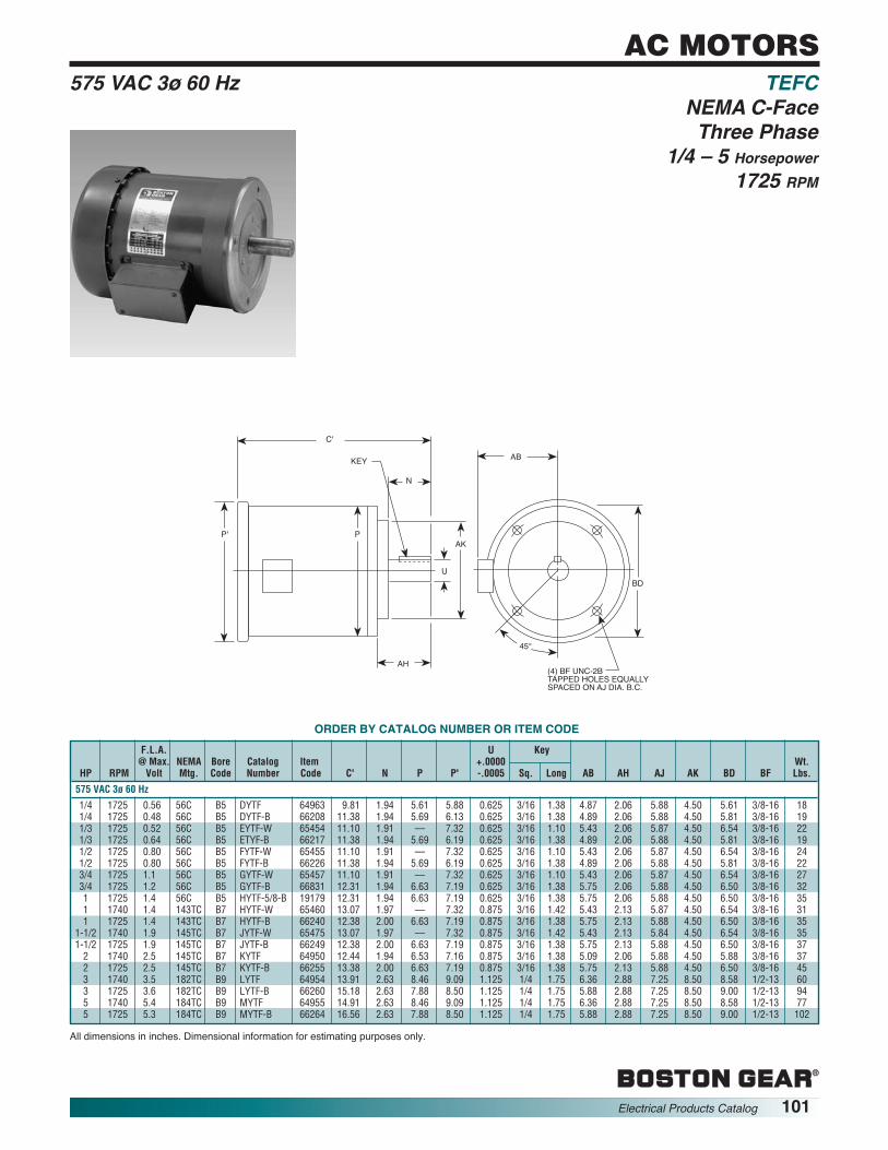
®
AC MOTORS
®
Electrical Products Catalog 101
F.L.A. U Key@ Max. NEMA Bore Catalog Item +.0000
HP RPM Volt Mtg. Code Number Code C' N P P' -.0005 Sq. Long AB
575 VAC 3ø 60 Hz
1/4 1725 0.56 56C B5 DYTF 64963 9.81 1.94 5.61 5.88 0.625 3/16 1.38 4.871/4 1725 0.48 56C B5 DYTF-B 66208 11.38 1.94 5.69 6.13 0.625 3/16 1.38 4.891/3 1725 0.52 56C B5 EYTF-W 65454 11.10 1.91 — 7.32 0.625 3/16 1.10 5.431/3 1725 0.64 56C B5 ETYF-B 66217 11.38 1.94 5.69 6.19 0.625 3/16 1.38 4.891/2 1725 0.80 56C B5 FYTF-W 65455 11.10 1.91 — 7.32 0.625 3/16 1.10 5.431/2 1725 0.80 56C B5 FYTF-B 66226 11.38 1.94 5.69 6.19 0.625 3/16 1.38 4.893/4 1725 1.1 56C B5 GYTF-W 65457 11.10 1.91 — 7.32 0.625 3/16 1.10 5.433/4 1725 1.2 56C B5 GYTF-B 66831 12.31 1.94 6.63 7.19 0.625 3/16 1.38 5.751 1725 1.4 56C B5 HYTF-5/8-B 19179 12.31 1.94 6.63 7.19 0.625 3/16 1.38 5.751 1740 1.4 143TC B7 HYTF-W 65460 13.07 1.97 — 7.32 0.875 3/16 1.42 5.431 1725 1.4 143TC B7 HYTF-B 66240 12.38 2.00 6.63 7.19 0.875 3/16 1.38 5.75
1-1/2 1740 1.9 145TC B7 JYTF-W 65475 13.07 1.97 — 7.32 0.875 3/16 1.42 5.431-1/2 1725 1.9 145TC B7 JYTF-B 66249 12.38 2.00 6.63 7.19 0.875 3/16 1.38 5.752 1740 2.5 145TC B7 KYTF 64950 12.44 1.94 6.53 7.16 0.875 3/16 1.38 5.092 1725 2.5 145TC B7 KYTF-B 66255 13.38 2.00 6.63 7.19 0.875 3/16 1.38 5.753 1740 3.5 182TC B9 LYTF 64954 13.91 2.63 8.46 9.09 1.125 1/4 1.75 6.363 1725 3.6 182TC B9 LYTF-B 66260 15.18 2.63 7.88 8.50 1.125 1/4 1.75 5.885 1740 5.4 184TC B9 MYTF 64955 14.91 2.63 8.46 9.09 1.125 1/4 1.75 6.365 1725 5.3 184TC B9 MYTF-B 66264 16.56 2.63 7.88 8.50 1.125 1/4 1.75 5.88
Wt.AH AJ AK BD BF Lbs.
2.06 5.88 4.50 5.61 3/8-16 182.06 5.88 4.50 5.81 3/8-16 192.06 5.87 4.50 6.54 3/8-16 222.06 5.88 4.50 5.81 3/8-16 192.06 5.87 4.50 6.54 3/8-16 242.06 5.88 4.50 5.81 3/8-16 222.06 5.87 4.50 6.54 3/8-16 272.06 5.88 4.50 6.50 3/8-16 322.06 5.88 4.50 6.50 3/8-16 352.13 5.87 4.50 6.54 3/8-16 312.13 5.88 4.50 6.50 3/8-16 352.13 5.84 4.50 6.54 3/8-16 352.13 5.88 4.50 6.50 3/8-16 372.06 5.88 4.50 5.88 3/8-16 372.13 5.88 4.50 6.50 3/8-16 452.88 7.25 8.50 8.58 1/2-13 602.88 7.25 8.50 9.00 1/2-13 942.88 7.25 8.50 8.58 1/2-13 772.88 7.25 8.50 9.00 1/2-13 102
575 VAC 3ø 60 Hz TEFCNEMA C-FaceThree Phase
1/4 – 5 Horsepower1725 RPM
ORDER BY CATALOG NUMBER OR ITEM CODE
All dimensions in inches. Dimensional information for estimating purposes only.
EP08
0A
C'
KEY
N
P
AH
U
AB
BD
(4) BF UNC-2BTAPPED HOLES EQUALLYSPACED ON AJ DIA. B.C.
45°
AKP'

®
AC MOTORS
®
102 Electrical Products Catalog
F.L.A. U Key@ Max. NEMA Bore Catalog Item +.0000
HP RPM Volt Mtg. Code Number Code C' N P P' -.0005 Sq. Long AB
110/220 VAC 1ø 50 Hz
1/6 1425 2.1 42CZ B4 ACR5TF-B 50480 9.31 1.15 4.69 5.19 0.500 1/8 0.75 4.031/4 1425 2.3 42CZ B4 ADR5TF-B 66970 9.31 1.15 4.69 5.19 0.500 1/8 0.75 4.031/4 1425 2.8 56C B5 DR5TF-B 66858 11.38 1.94 5.69 6.19 0.625 3/16 1.38 4.511/3 1425 3.1 56C B5 ER5TF-B 66869 12.38 1.94 5.69 6.19 0.625 3/16 1.38 4.511/2 1425 4.0 56C B5 FR5TF-B 66875 12.88 1.94 5.69 6.19 0.625 3/16 1.38 4.513/4 1425 6.4 56C B5 GR5TF-B 66881 13.31 1.94 6.63 7.19 0.625 3/16 1.38 5.25
220/380/415-440 VAC 3ø 50 Hz
1/2 1425 1.0 56C B5 FU5TF-B 50337 11.38 1.94 5.69 6.19 0.625 3/16 1.38 4.513/4 1425 1.3 56C B5 GU5TF-B 50338 12.00 1.94 5.69 6.19 0.625 3/16 1.38 4.511 1425 1.5 143TC B7 HU5TF-B 50339 12.38 2.00 6.63 7.19 0.875 3/16 1.38 5.25
1-1/2 1425 2.1 145TC B7 JU5TF-B 50340 13.38 2.00 6.63 7.19 0.875 3/16 1.38 5.25
Wt.AH AJ AK BD BF XO Lbs.
1.28 3.75 3.00 4.63 1/4-20 1.66 201.28 3.75 3.00 4.63 1/4-20 1.66 212.06 5.88 4.50 5.81 3/8-16 1.56 232.06 5.88 4.50 5.81 3/8-16 1.56 262.06 5.88 4.50 5.81 3/8-16 1.56 302.06 5.88 4.50 6.50 3/8-16 2.25 42
2.06 5.88 4.50 5.81 3/8-16 — 222.06 5.88 4.50 5.81 3/8-16 — 322.13 5.88 4.50 6.50 3/8-16 — 352.13 5.88 4.50 6.50 3/8-16 — 37
110/220 1ø 50 Hz TEFC220/380/440 3ø 50 Hz NEMA C-Face
Single and Three Phase, 50 Hz1/6 – 1-1/2 Horsepower
1425 RPM
EP07
9A
C'
KEY
N
P
AH
U
AB
BD
(4) BF UNC-2BTAPPED HOLES EQUALLYSPACED ON AJ DIA. B.C.
45°
XO
AKP'
ORDER BY CATALOG NUMBER OR ITEM CODE
All dimensions in inches. Dimensional information for estimating purposes only.

®
AC MOTORS
®
Electrical Products Catalog 103
EP08
1A
C
KEY
N
P
AH
U
AB
BD
(4) BF UNC-2BTAPPED HOLES EQUALLYSPACED ON AJ DIA. B.C.
45°
AKP'
Wt.AH AJ AK BD BF Lbs.
2.06 5.88 4.50 6.62 3/8-16 302.06 5.88 4.50 6.62 3/8-16 342.06 5.88 4.50 6.62 3/8-16 382.13 5.88 4.50 6.62 3/8-16 392.13 5.88 4.50 6.62 3/8-16 402.13 5.88 4.50 6.62 3/8-16 442.88 7.25 8.50 9.00 1/2-13 612.88 7.25 8.50 9.00 1/2-13 76
2.06 5.88 4.50 6.53 3/8-16 342.06 5.88 4.50 6.53 3/8-16 382.06 5.88 4.50 6.53 3/8-16 392.13 5.88 4.50 6.53 3/8-16 392.13 5.88 4.50 6.53 3/8-16 462.13 5.88 4.50 6.53 3/8-16 49
2.06 5.88 4.50 6.53 3/8-16 342.06 5.88 4.50 6.53 3/8-16 382.06 5.88 4.50 6.53 3/8-16 392.13 5.88 4.50 6.53 3/8-16 392.13 5.88 4.50 6.53 3/8-16 462.13 5.88 4.50 6.53 3/8-16 49
208-230/460 VAC 3ø 60 Hz BISSC Approved Washdown575 VAC 3ø 60 Hz & Stainless Steel
NEMA C-FaceThree PhaseTENV-TEFC
1/2 – 5 Horsepower1725 RPM
ORDER BY CATALOG NUMBER OR ITEM CODE
All dimensions in inches. Dimensional information for estimating purposes only.*TEFC, All other TENV
F.L.A. U Key@ Max. NEMA Bore Catalog Item +.0000
HP Volt Mtg. Code Number Code C N P P’ -.0005 Sq. Lg. AB
208-230/460 VAC 3ø 60 Hz BISCC Approved
1/2 0.80 56C B5 FUT-WB-B 69105 11.06 1.94 6.63 — 0.625 3/16 1.38 5.253/4 1.1 56C B5 GUT-WB-B 69106 11.06 1.94 6.63 — 0.625 3/16 1.38 5.251 1.5 56C B5 HUT-WB-5/8-B 69123 12.13 1.94 6.63 — 0.625 3/16 1.38 5.251 1.7 143TC B7 HUT-WB-B 69107 12.13 2.00 6.63 — 0.875 3/16 1.38 5.25
1-1/2 2.5 145TC B7 JUTF-WB-B * 69110 12.38 2.00 6.63 7.19 0.875 3/16 1.38 5.252 3.1 145TC B7 KUTF-WB-B * 69111 13.38 2.00 6.63 7.19 0.875 3/16 1.38 5.253 4.3 182TC B9 LUTF-WB-B * 69112 15.19 2.62 7.88 8.50 1.125 1/4 1.75 5.885 6.6 184TC B9 MUTF-WB-B * 69113 16.56 2.62 7.88 8.50 1.125 1/4 1.75 5.88
208-230/460 VAC 3ø 60 Hz Stainless Steel
1/2 1.4 56C B5 FUT-SS 46488 11.56 1.94 6.53 — 0.625 3/16 1.38 5.443/4 2.2 56C B5 GUT-SS 46630 12.06 1.94 6.53 — 0.625 3/16 1.38 5.441 2.9 56C B5 HUT-5/8-SS 46634 12.06 1.94 6.53 — 0.625 3/16 1.38 5.441 2.9 143TC B7 HUT-SS 46635 12.13 2.00 6.53 — 0.875 3/16 1.38 5.44
1-1/2 4.4 145TC B7 JUTF-SS 46636 14.25 2.00 6.53 — 0.875 3/16 1.38 5.442 6.0 145TC B7 KUTF-SS 46639 14.25 2.00 6.53 — 0.875 3/16 1.38 5.44
575 VAC 3ø 60 Hz Stainless Steel
1/2 1.4 56C B5 FYT-SS 59000 11.56 1.94 6.53 — 0.625 3/16 1.38 5.443/4 2.2 56C B5 GYT-SS 59001 12.06 1.94 6.53 — 0.625 3/16 1.38 5.441 2.9 56C B5 HYT-5/8-SS 59003 12.06 1.94 6.53 — 0.625 3/16 1.38 5.441 2.9 143TC B7 HYT-SS 59002 12.13 2.00 6.53 — 0.875 3/16 1.38 5.44
1-1/2 4.4 145TC B7 JYTF-SS 59004 14.25 2.00 6.53 — 0.875 3/16 1.38 5.442 6.0 145TC B7 KYTF-SS 59005 14.25 2.00 6.53 — 0.875 3/16 1.38 5.44

®
AC MOTORS
®
104 Electrical Products Catalog
EP08
2A
C
KEY
N
P
AH
U
AB
BD
(4) BF UNC-2BTAPPED HOLES EQUALLYSPACED ON AJ DIA. B.C.
45°
AK
XO
ORDER BY CATALOG NUMBER OR ITEM CODEBrake F.L.A. U KeyRating @ Max. NEMA Bore Catalog Item +.0000 Wt.
HP (Lb. Ft.) VOLT MTG. CODE Number Code C N P -.0005 Sq. Lg. AB AH AJ AK BD BF XO Lbs.
115/230 VAC 1ø 60 Hz
1/4 3 2.5 56C B5 DRB-B 66361 14.19 1.88 5.69 .625 3/16 1.38 4.88 2.06 5.88 4.50 5.81 3/8-16 2.20 341/3 3 3.0 56C B5 ERB-B 66370 15.19 1.88 5.69 .625 3/16 1.38 4.88 2.06 5.88 4.50 5.81 3/8-16 2.20 341/2 3 4.2 56C B5 FRB-B 66379 16.19 1.88 5.69 .625 3/16 1.38 4.88 2.06 5.88 4.50 5.81 3/8-16 2.20 383/4 3 5.4 56C B5 GRB-B 66388 15.25 1.88 6.63 .625 3/16 1.38 5.63 2.06 5.88 4.50 6.50 3/8-16 2.28 45
208-230/460 VAC 3ø 60 Hz
1/4 3 0.65 56C B5 DUB-B 66364 14.19 1.88 5.69 .625 3/16 1.38 4.88 2.06 5.88 4.50 5.81 3/8-16 — 261/3 3 0.80 56C B5 EUB-B 66373 14.19 1.88 5.69 .625 3/16 1.38 4.88 2.06 5.88 4.50 5.81 3/8-16 — 281/2 3 1.0 56C B5 FUB-B 66382 14.19 1.88 5.69 .625 3/16 1.38 4.88 2.06 5.88 4.50 5.81 3/8-16 — 313/4 3 1.5 56C B5 GUB-B 66391 15.25 1.88 6.63 .625 3/16 1.38 5.63 2.06 5.88 4.50 6.50 3/8-16 — 411 3 1.7 56C B5 HUB-5/8-B 19181 15.25 1.88 6.63 .625 3/16 1.38 5.47 2.06 5.88 4.50 6.50 3/8-16 — 311 3 1.7 143TC B7 HUB-B 66397 15.31 2.00 6.63 .875 3/16 1.38 5.25 2.13 5.88 4.50 6.50 3/8-16 — 401-1/2 6 2.4 145TC B7 JUB-B 66403 15.31 2.00 6.63 .875 3/16 1.38 5.25 2.13 5.88 4.50 6.50 3/8-16 — 432 6 3.2 145TC B7 KUB-B 66409 16.31 2.00 6.63 .875 3/16 1.38 5.25 2.13 5.88 4.50 6.50 3/8-16 — 533 10 4.3 182TC B9 LUB-B 66415 18.19 2.63 7.88 1.125 1/4 1.75 5.88 2.89 7.25 8.50 9.00 1/2-13 — 735 10 7.0 184TC B9 MUB-B 66834 19.56 2.63 7.88 1.125 1/4 1.75 5.88 2.89 7.25 8.50 9.00 1/2-13 — 84
115/230 1ø 60 Hz Brake Motors, Open Dripproof208-230/460 3ø 60 Hz NEMA C-Face
Single and Three Phase1/4 – 5 Horsepower
1725 RPM
All dimensions in inches. Dimensional information for estimating purposes only.

®
AC MOTORS
®
Electrical Products Catalog 105
EP08
3A
C'
KEY
N
P
AH
U
AB
BD
(4) BF UNC-2BTAPPED HOLES EQUALLYSPACED ON AJ DIA. B.C.
45°
AK
XO
P'
Brake F.L.A. U KeyRating @ Max. NEMA Bore Catalog Item +.0000
HP (lb ft) Volt Mtg. Code Number Code C' N P P’ -.0005 Sq. Lg. AB AH AJ
115/230 VAC 1ø 60 Hz
1/4 3 2.5 56C B5 DRTB-B 66419 15.19 1.88 5.68 — .625 3/16 1.38 4.88 2.06 5.881/3 3 2.4 56C B5 ERTB-B 66431 16.19 1.88 5.68 — .625 3/16 1.38 4.88 2.06 5.881/2 3 3.4 56C B5 FRTB-B 66440 16.25 1.88 6.63 — .625 3/16 1.38 5.75 2.06 5.883/4 3 5.6 56C B5 GRTFB-B* 66449 17.88 1.88 6.63 7.18 .625 3/16 1.38 5.75 2.06 5.88
208-230/460 VAC 3ø 60 Hz
1/4 3 0.60 56C B5 DUTB-B 66425 14.19 1.88 5.68 — .625 3/16 1.38 4.88 2.06 5.881/3 3 0.70 56C B5 EUTB-B 66434 14.19 1.88 5.68 — .625 3/16 1.38 4.88 2.06 5.881/2 3 0.90 56C B5 FUTB-B 66443 14.81 1.88 5.69 — .625 3/16 1.38 4.89 2.06 5.883/4 3 1.1 56C B5 GUTB-B 66452 15.25 1.88 6.63 — .625 3/16 1.38 5.75 2.06 5.881 3 1.5 56C B5 HUTB-5/8-B 19182 16.25 1.88 6.63 — .625 3/16 1.38 5.75 2.06 5.881 3 1.5 145TC B7 HUTB-B 66458 16.31 2.00 6.63 — .875 3/16 1.38 5.75 2.3 5.88
1-1/2 6 2 5 145TC B7 JUTFB-B* 66464 16.94 2.00 6.63 7.18 .875 3/16 1.38 5.75 2.13 5.882 6 3.1 145TC B7 KUTFB-B* 66470 17.94 2.00 6.63 7.18 .875 3/16 1.38 5.75 2.13 5.883 10 4.3 182TC B9 LUTFB-B* 66474 19.81 2.63 8.50 7.18 1.125 1/4 1.75 5.88 2.88 7.855 25 6.6 184TC B9 MUTFB-B* 66838 21.18 2.63 7.89 10.18 1.125 1/4 1.75 5.97 2.88 7.25
575 VAC 3ø 60 Hz
1/4 3 .40 56C B5 DYTB-B 66428 15.25 1.88 6.63 — .625 3/16 1.38 5.63 2.06 5.081/2 3 .72 56C B5 FYTB-B 66446 15.19 1.88 5.81 — .625 3/16 1.38 4.88 2.06 5.883/4 3 1.2 56C B5 GYTB-B 66455 15.19 1.88 5.81 — .625 3/16 1.38 4.88 2.06 5.881 3 1.2 145TC B7 HYTB-B 66461 16.31 2.00 6.63 — .875 3/16 1.38 5.75 2.13 5.88
1-1/2 6 2.0 145TC B7 JYTFB-B* 66467 16.94 2.00 6.63 7.18 .875 3/16 1.38 5.75 2.13 5.882 6 2.5 145TC B7 KYTFB-B* 66472 17.94 2.00 6.63 7.18 .875 3/16 1.38 5.75 2.13 5.883 10 3.6 182TC B9 LYTFB-B* 66476 19.81 2.63 8.50 7.18 1.125 1/4 1.75 5.88 2.88 7.255 10 5.3 184TC B9 MYTFB-B* 66840 21.18 2.63 8.50 7.18 1.125 1/4 1.75 5.88 2.88 7.25
Approx.Wght.
AK BD BF XO (lb)
4.50 5.81 3/8-16 1.54 344.50 5.81 3/8-16 1.54 384.50 6.50 3/8-16 2.30 394.50 6.50 3/8-16 2.30 48
4.50 5.81 3/8-16 — 254.50 5.81 3/8-16 — 274.50 5.81 3/8-16 — 304.50 6.50 3/8-16 — 404.50 6.50 3/8-16 — 414.50 6.50 3/8-16 — 414.50 6.50 3/8-16 — 434.50 6.50 3/8-16 — 518.50 9.00 1/2-13 — 768.50 8.86 1/2-13 — 118
4.50 5.81 3/8-16 — 304.50 5.81 3/8-16 — 304.50 5.81 3/9-16 — 404.50 6.50 3/8-16 — 514.50 6.50 3/8-16 — 434.50 6.50 3/8-16 — 518.50 9.00 1/2-13 — 768.50 9.00 1/2-13 — 112
115/230 VAC 1ø 60 Hz Brake Motors208-230/460 VAC 3ø 60 Hz TEFC & TENV575 VAC 3ø 60 Hz NEMA C-Face
Single and Three Phase1/4 – 5 Horsepower
1725 RPM
ORDER BY CATALOG NUMBER OR ITEM CODE
*TEFC, All others TENV.All dimensions in inches. Dimensional information for estimating purposes only.

®
AC MOTORS
®
106 Electrical Products Catalog
CONTINUOUS DUTY1.0 SERVICE FACTORCLASS I GROUP DCLASS II GROUPS F & G
EP08
0A
C'
KEY
N
P
AH
U
AB
BD
(4) BF UNC-2BTAPPED HOLES EQUALLYSPACED ON AJ DIA. B.C.
45°
AKP'
F.L.A. U KEY@ Max. NEMA Bore Catalog Item +.0000 Wt.
HP Volt Mtg. Code Number Code C' N P P' -.0005 Sq. Lg. AB AH AJ AK BD BF Lbs.
115/230 VAC 1ø 60 Hz
1/4 2.5 56C B5 DRX-B 66292 14.38 1.94 6.68 7.19 0.625 3/16 1.38 6.75 2.06 5.88 4.50 6.50 3/8-16 421/3 3.0 56C B5 ERX-B 66304 14.38 1.94 6.68 7.19 0.625 3/16 1.38 6.75 2.06 5.88 4.50 6.50 3/8-16 421/2 3.8 56C B5 FRX-B 66313 14.38 1.94 6.75 7.19 0.625 3/16 1.38 6.75 2.06 5.88 4.50 6.50 3/8-16 493/4 5.3 56C B5 GRX-B 66322 15.25 1.94 6.75 7.19 0.625 3/16 1.38 6.75 2.06 5.88 4.50 6.50 3/8-16 54
208-230/460 VAC 3ø 60 Hz
1/4 0.65 56C B5 DUX-B 66298 14.38 1.94 6.68 7.19 0.625 3/16 1.38 6.75 2.06 5.88 4.50 6.50 3/8-16 421/3 0.80 56C B5 EUX-B 66307 13.22 1.94 6.68 6.20 0.625 3/16 1.38 6.50 2.06 5.88 4.50 6.50 3/8-16 281/2 1.0 56C B5 FUX-B 66316 14.38 1.94 6.68 7.19 0.625 3/16 1.38 6.75 2.06 5.88 4.50 6.50 3/8-16 423/4 1.5 56C B5 GUX-B 66325 14.38 1.94 6.68 7.19 0.625 3/16 1.38 6.75 2.06 5.88 4.50 6.50 3/8-16 431 1.8 56C B5 HUX-5/8-B 19180 — 1.94 6.68 6.20 0.625 3/16 1.38 6.50 2.06 5.88 4.50 6.50 3/8-16 441 1.7 143TC B7 HUX-B 66334 — 2.00 6.68 7.19 0.875 3/16 1.38 6.92 2.13 5.88 4.50 6.50 3/8-16 39
1-1/2 2.5 145TC B7 JUX-B 66343 — 2.00 6.88 7.19 0.875 3/16 1.38 6.92 2.13 5.88 4.50 6.50 3/8-16 432 3.1 145TC B7 KUX-B 66349 — 2.00 6.75 7.19 0.875 3/16 1.38 6.92 2.13 5.88 4.50 6.50 3/8-16 503 4.3 182TC B9 LUX-B 66353 17.50 2.63 7.88 8.49 1.125 1/4 1.75 7.52 2.88 7.25 8.50 8.98 1/2-13 815 6.5 184TC B9 MUX-B 66357 — 2.63 7.88 8.82 1.125 1/4 1.75 7.52 2.88 7.25 8.50 8.98 1/2-13 111
115/230 VAC 1ø 60 Hz Explosion Proof208-230/460 VAC 3ø 60 Hz NEMA C-Face
Single and Three Phase1/4-5 Horsepower
1725 RPM
ORDER BY CATALOG NUMBER OR ITEM CODE
All dimensions in inches. Dimensional information for estimating purposes only.

®
AC MOTORS
®
Electrical Products Catalog 107
U Key+.0000 Wt.-.0005 SQ Long V AB XO (Lbs.)
.625 3/16 1.38 1.88 4.88 1.50 27
.625 3/16 1.38 1.88 5.75 2.25 35
.875 3/16 1.38 2.25 5.75 2.25 39
.875 3/16 1.38 2.25 5.75 2.25 48
.625 3/16 1.38 1.88 4.88 –– 23
.625 3/16 1.38 1.88 4.88 –– 26
.875 3/16 1.38 2.25 5.75 –– 32
.875 3/16 1.38 2.25 5.75 –– 41
.875 3/16 1.38 2.25 5.75 –– 421.125 1/4 1.75 2.75 5.88 –– 551.125 1/4 1.75 2.75 5.88 –– 751.375 5/16 2.38 3.38 7.38 –– 991.375 5/16 2.38 3.38 7.38 –– 1271.625 3/8 3.00 4.00 8.86 –– 2441.625 3/8 3.00 4.00 9.50 –– 2691.875 1/2 3.63 4.63 12.63 –– 3591.875 1/2 3.63 4.63 13.12 –– 4332.125 1/2 4.25 5.25 14.62 –– 5832.125 1/2 4.25 5.25 14.13 –– 526
C
M N
V
U
KEY
O
D
E E
PAB
XO
HHOLE
F F
P'
EP50
4A
ORDER BY CATALOG NUMBER OR ITEM CODEF.L.A.@ Max. NEMA Catalog Item
HP RPM Volt MTG Number Code C D E F H* M N O P P′′
115/230 VAC 1ø 60 Hz
1/2 1725 3.7 56 BFRTF-B 66530 11.95 3.50 2.44 1.50 .34(S) 3.63 2.50 6.34 5.68 6.133/4 1725 5.6 56 BGRTF-B 66536 13.31 3.50 2.44 1.50 .34(S) 3.69 2.50 6.88 6.63 7.181 1725 6.2 143T BHRTF-B 66542 13.31 3.50 2.75 2.00 .34(S) 4.00 2.50 6.81 6.63 7.18
1-1/2 1725 8.0 145T BJRTF-B 66548 14.19 3.50 2.75 2.00 .34(S) 4.00 2.50 6.81 6.63 7.18
208-230/460 VAC 3ø 60 Hz
1/2 1725 1.0 56 BFUTF-B 66533 11.38 3.60 2.44 1.50 .34(S) 3.63 2.50 6.38 5.68 6.133/4 1725 1.5 56 BGUTF-B 66538 12.38 3.50 2.44 1.50 .34(S) 3.63 2.50 6.38 5.68 6.131 1725 1.7 143T BHUTF-B 66544 12.38 3.50 2.75 2.00 .34(S) 4.00 2.50 6.88 6.63 7.18
1-1/2 1725 2.5 145T BJUTF-B 66550 13.31 3.50 2.75 2.00 .34(S) 4.00 2.50 6.81 6.63 7.182 1725 3.1 145T BKUTF-B 66554 13.38 3.50 2.75 2.00 .34(S) 4.00 2.50 6.88 6.63 7.183 1750 4.3 182T BLUTF-B 61314 15.18 4.50 3.75 2.25 .41 4.19 3.56 8.44 7.88 8.505 1750 6.6 184T BMUTF-B 61316 16.56 4.50 3.75 2.25 .41 4.19 3.56 8.44 7.88 8.50
7-1/2 1750 10.0 213T BNUTF-B 61318 17.94 5.25 4.25 2.75 .41 5.75 3.88 10.06 9.56 10.1810 1750 13.0 215T BPUTF-B 61320 19.06 5.25 4.25 2.75 .41 5.75 3.88 10.06` 9.56 10.1815 1760 19.6 254T BRUTF-B 66886 21.09 6.25 5.00 4.13 .53 8.06 4.31 12.18 12.94 10.6220 1760 26.0 256T BSUTF-B 61341 23.18 6.25 5.00 5.00 .53 8.94 4.31 12.88 12.94 13.2525 1760 30.0 284T BTUTF-B 61343 27.28 7.00 5.50 4.75 .53 9.44 4.75 15.56 14.63 15.0030 1760 37.0 286T BUUTF-B 61345 27.76 7.00 5.50 5.50 .53 10.29 4.75 14.44 14.63 15.0040 1760 46.5 324T BVUTF-B 61347 30.25 8.00 6.25 5.25 .66 10.31 5.44 16.25 17.38 16.9450 1760 62.0 326T BWUTF-B 61349 30.25 8.00 6.25 6.00 .66 11.06 5.44 16.50 17.38 16.94
115/230 VAC 1ø 60 Hz TEFC208-230/460 VAC 3ø 60 Hz Rigid Base
Single and Three Phase1/2 – 50 Horsepower
1725 RPM
All dimensions in inches. Dimensional information for estimating purposes only.*(S) Slotted (Dimension is Width)

®
AC MOTORS
®
108 Electrical Products Catalog
Boston Gear’s Inverter Drive motors are specifically designed for today’s toughadjustable speed applications. The design uses a rugged ribbed (for cooling) castiron frame*, endplates and connection box. The motors feature a cast iron base andC-face mounting. Locked bearings allow for vertical wall and horizontal mountingswithout modifications. These motors are fully insulated (Class H) for protectionagainst voltage spikes which could cause phase to phase or turn to turn shorts. Alsoincluded are normally closed thermal protectors for overheating protection. Thesemotors are offered at 1800 RPM base speed in a TENV or TEBC enclosure. Alsoavailable 1150 RPM Base Speed in a TEBC Enclosure.
*1 HP and above
F.L.A. U KeyRPM @ @ Max. NEMA Bore Catalog +.0000
HP 60 Hz Volt Mtg. Code Number C D E 2F H O –.0005 Sq Long AB
Totally Enclosed, Non-Ventilated 230/460-3-60 VAC
1/3 1725 0.50 56C B5 EUT-ID-B 10.25 3.50 2.44 3.00 .34(S) 6.34 .625 3/16 1.38 4.511/2 1725 0.65 56C B5 FUT-ID-B 10.88 3.50 2.44 3.00 .34(S) 6.34 .625 3/16 1.38 4.513/4 1725 0.65 56C B5 GUT-ID-B 11.50 3.50 2.44 3.00 .34(S) 6.88 .625 3/16 1.38 5.251 1725 1.6 143TC B7 HUT-ID-B 11.82 3.50 2.75 4.00 .38 7.59 .875 3/16 1.38 6.33
1-1/2 1725 2.1 143TC B7 JUT-ID-B 11.82 3.50 2.75 4.00 .38 7.59 .875 3/16 1.38 6.332 1725 2.9 182TC B9 KUT-ID-B 14.86 4.50 3.75 4.50 .41 9.23 1.125 1/4 1.75 7.083 1750 4.0 184TC B9 LUT-ID-B 14.86 4.50 3.75 5.50 .41 9.23 1.125 1/4 1.75 7.085 1760 6.7 213TC B11 MUT-ID-B 18.07 5.25 4.25 5.50 .41 10.99 1.375 5/16 2.38 8.61
7-1/2 1760 10.0 254TC B13 NUT-ID-B 21.67 6.25 5.00 8.25 .53 12.87 1.625 3/8 2.88 9.4210 1760 12.8 256TC B13 PUT-ID-B 21.67 6.25 5.00 10.00 .53 12.87 1.625 3/8 2.88 9.42
Wt.AH AJ AK BA BB BD BF Lbs.
1.94 5.88 4.50 2.69 .12 5.81 3/8-16 241.94 5.88 4.50 2.69 .12 5.81 3/8-16 261.94 5.88 4.50 2.69 .12 6.50 3/8-16 422.00 5.88 4.50 2.38 .12 6.50 3/8-16 542.00 5.88 4.50 2.38 .12 6.50 3/8-16 632.62 7.25 8.50 3.38 .25 9.00 1/2-13 1052.62 7.25 8.50 3.38 .25 9.00 1/2-13 1243.12 7.25 8.50 4.25 .25 9.06 1/2-13 1703.75 7.25 8.50 4.75 .25 9.09 1/2-13 2043.75 7.25 8.50 4.75 .25 9.09 1/2-13 265
Totally Enclosed Inverter DutyNonventilated 1/3–10 Horsepower
ORDER BY CATALOG NUMBER
All dimensions in inches. (S) Slotted (Dimension is width).Dimensional information for estimating purposes only.
C
AH
BBGREASER & RELIEF
EACH ENDKEY
U
AK BD
AUTO. DRAINEACH ENDH. HOLES
2F BA
AB
EE
D
O
45° 45°
EP08
5A
(4) BF UNC-2B TAPPED HOLES EQUALLYSPACED ON AJ DIA. B.C.

®
AC MOTORS
®
Electrical Products Catalog 109
F.L.A. U KeyRPM @ @Max. NEMA Bore Catalog +.0000
HP 60 Hz Volt Mtg. Code Number C D E 2F H O –.0005 Sq Long AB
Totally Enclosed, Blower Cooled 230/460-3-60 VAC
1 1725 1.7 143TC B7 HUBC-ID-B 18.65 3.50 2.75 4.00 .38 7.59 .875 3/16 1.38 6.331 1150 1.5 145TC B7 HUBC-11-ID-B 18.65 3.50 2.75 5.00 .38 7.59 .875 3/16 1.38 6.33
1-1/2 1725 2.5 145TC B7 JUBC-ID-B 18.65 3.50 2.75 5.00 .38 7.59 .875 3/16 1.38 6.331-1/2 1140 2.6 182TC B9 JUBC-11-ID-B 21.73 4.50 3.75 4.50 .41 9.23 1.125 1/4 1.75 7.082 1750 3.1 145TC B7 KUBC-ID-B 18.65 3.50 2.75 5.00 .38 7.59 .875 3/16 1.38 6.332 1160 2.8 184TC B9 KUBC-11-ID-B 21.73 4.50 3.75 5.50 .41 9.23 1.125 1/4 1.75 7.083 1760 4.5 184TC B9 LUBC-ID-B 21.73 4.50 3.75 5.50 .41 9.23 1.125 1/4 1.75 7.083 1160 5.0 213TC B11 LUBC-11-ID-B 25.39 5.25 4.25 5.50 .41 10.99 1.375 5/16 2.38 8.615 1760 6.8 184TC B9 MUBC-ID-B 21.73 4.50 3.75 5.50 .41 9.23 1.125 1/4 1.75 7.085 1160 7.7 215TC B11 MUBC-11-ID-B 25.39 5.25 4.25 7.00 .41 10.99 1.375 5/16 2.38 8.61
7-1/2 1760 9.8 213TC B11 NUBC-ID-B 25.39 5.25 4.25 5.50 .41 10.99 1.375 5/16 2.38 8.617-1/2 1170 10.2 254TC B13 NUBC-11-ID-B 29.29 6.25 5.00 8.25 .53 12.87 1.625 3/8 2.88 9.4210 1760 12.7 215TC B11 PUBC-ID-B 25.39 5.25 4.25 7.00 .41 10.99 1.375 5/16 2.38 8.6110 1170 14.0 256TC B13 PUBC-11-ID-B 29.29 6.25 5.00 10.00 .53 12.87 1.625 3/8 2.88 9.4215 1760 18.0 256TC B13 RUBC-ID-B 29.29 6.25 5.00 10.00 .53 12.87 1.625 3/8 2.88 9.4215 1170 19.5 284TC * RUBC-11-ID-B 32.82 7.00 5.50 9.50 .56 14.44 1.875 1/2 3.25 12.9620 1780 24.0 256TC B13 SUBC-ID-B 29.29 6.25 5.00 10.00 .53 12.87 1.625 3/8 2.88 9.4220 1170 26.0 286TC * SUBC-11-ID-B 32.82 7.00 5.50 11.00 .56 14.44 1.875 1/2 3.25 12.9625 1780 30.4 284TC * TUBC-ID-B 32.82 7.00 5.50 9.50 .56 14.44 1.875 1/2 3.25 12.9625 1180 29.8 324TC * TUBC-11-ID-B 35.23 8.00 6.25 10.50 .65 16.23 2.125 1/2 3.88 14.4630 1780 35.5 286TC * UUBC-ID-B 32.82 7.00 5.50 11.00 .56 14.44 1.875 1/2 3.25 12.9630 1180 36.0 326TC * UUBC-11-ID-B 35.23 8.00 6.25 12.00 .65 16.23 2.123 1/2 3.88 14.4640 1780 46.5 324TC * VUBC-ID-B 35.23 8.00 6.25 10.50 .65 16.23 2.125 1/2 3.88 14.4640 1180 47.0 364TC * VUBC-11-ID-B 37.13 9.00 7.00 11.25 .66 18.38 2.375 5/8 4.25 14.8050 1780 57.5 326TC * WUBC-ID-B 35.23 8.00 6.25 12.00 .65 16.23 2.125 1/2 3.88 14.4650 1180 59.0 365TC * WUBC-11-ID-B 37.13 9.00 7.00 12.25 .66 18.38 2.375 5/8 4.25 14.8060 1780 71.0 364TC * XUBC-ID-B 37.13 9.00 7.00 11.25 .66 18.38 2.375 5/8 4.25 14.8075 1780 86.0 365TC * YUBC-ID-B 37.13 9.00 7.00 12.25 .66 18.38 2.375 5/8 4.25 14.80
Wt.AH AJ AK BA BB BD BF Lbs.
2.00 5.88 4.50 2.38 .12 6.50 3/8-16 582.00 5.88 4.50 2.38 .12 6.50 3/8-16 602.00 5.88 4.50 2.38 .12 6.50 3/8-16 612.63 7.25 8.50 3.38 .25 9.00 1/2-13 962.00 5.88 4.50 2.25 .12 6.50 3/8-16 672.63 7.25 8.50 3.38 .25 9.00 1/2-13 1002.63 7.25 8.50 3.38 .25 9.00 1/2-13 1133.12 7.25 8.50 4.25 .25 9.06 1/2-13 1572.63 7.25 8.50 3.38 .25 9.00 1/2-13 1323.12 7.25 8.50 4.25 .25 9.06 1/2-13 1823.12 7.25 8.50 4.25 .25 9.06 1/2-13 1803.75 7.25 8.50 4.75 .25 9.09 1/2-13 2353.12 7.25 8.50 4.25 .25 9.06 1/2-13 2103.75 7.25 8.50 4.75 .25 9.09 1/2-13 3003.75 7.25 8.50 4.75 .25 9.09 1/2-13 2754.38 9.00 10.50 4.75 .25 11.21 1/2-13 4503.75 7.25 8.50 4.75 .25 9.09 1/2-13 3114.38 9.00 10.50 4.75 .25 11.21 1/2-13 4594.38 9.00 10.50 4.75 .25 11.21 1/2-13 4085.00 11.00 12.50 5.25 .25 13.40 5/8-11 5714.38 9.00 10.50 4.75 .25 11.21 1/2-13 4705.00 11.00 12.50 5.25 .25 13.40 5/8-11 6125.00 11.00 12.50 5.25 .25 13.40 5/8-11 5475.62 11.00 12.50 5.88 .25 12.89 5/8-11 7475.00 11.00 12.50 5.25 .25 13.40 5/8-11 6705.62 11.00 12.50 5.88 .25 12.89 5/8-11 8355.62 11.00 12.50 5.88 .25 12.89 5/8-11 7975.62 11.00 12.50 5.88 .25 12.89 5/8-11 869
208-230/460 VAC 3ø 60 Hz Inverter DutyBlower CooledNEMA C-Face1–75 Horsepower
1150 & 1725 RPM
All dimensions in inches. Dimensional information for estimating purposes only.*Not standard BG mounting.
ORDER BY CATALOG NUMBER OR ITEM CODE
C
AH
BBGREASER & RELIEF
EACH ENDKEY
U
AK BD
AUTO. DRAINEACH ENDH. HOLES
2F BA
AB
EE
D
O
45° 45°
EP08
6A
CONN. LABEL(FAN LEADS)
(4) BF UNC-2B TAPPED HOLES EQUALLYSPACED ON AJ DIA. B.C.

®®
110 Electrical Products Catalog
NOTES

®
Electrical Products Catalog 111
WASHDOWN PRODUCTS
®
Boston Gear has developed a wide range of power transmission products specifically for the food and beverage industry. Workingwith design and maintenance personnel we have designed certain mechanical, electrical and electronic products to meet theirharsh washdown applications.
600 SERIES
700 SERIES
200 SERIES
D.C. MOTOR
A.C. MOTORBRAKE
A.C. MOTORCONTROL
D.C. MOTORCONTROL
SENSOR
SENSOR
EP23
0A
CLUTCH
BRAKE
A COMPLETE VARIABLE SPEEDWASHDOWN POWER DRIVE SYSTEM
Mechanical • Electrical • Electronic
SPEED REDUCERS
700 Series — Stainless Bost-Kleen™
• Durable stainless steel epoxycoating system utilizes a uniquestainless steel leafing pigment
• USDA Approved for use in foodprocessing and handling industrywhere incidental food contact mayoccur
• BISSC Certified• Washable and scrubbable• Corrosion resistant• Prelubricated with USDA
Approved Mobil SHC634synthetic oil
• Double lipped oil seals• Excluder seal on output shaft• Limited lifetime warranty• Available up to 25 HP in 1” to 6”
Center distances
DC CONTROLLERS
BETA II/Beta Plus DC Controllers
• NEMA 4 washdown enclosure• 1/12 to 2 horsepower range• Reconnectable 115/230 VAC
input• Run/Stop/Job & Forward/Reverse
operation• Rugged, compact design• Durable non-absorbent, non-toxic
white epoxy finish, USDAapproved
• NEMA 4 washdown duty ACinverters also available
AC BRAKE
Double C-Face AC Brakes BISSC Certified
• Standard torque ranges from 3 to10 lb-ft
• Available with DC voltage coils• Automatic reset, manual brake
release• Rated for continuous duty• Available from stock

®
112 Electrical Products Catalog
WASHDOWN PRODUCTSAC/DC MOTORS
AC Motors (pg. 103)• 1/2 – 5 Horsepower• 230/460-3-60 VAC• BISSC Certified• Durable White Epoxy Finish• Totally Enclosed Design• NEMA C-Face Mounting• Weep Holes
DC Motors (pg. 88)• 1/4 – 3/4 Horsepower• 90 & 180 VAC• BISSC Certified• Durable White Epoxy• TENV• NEMA C-Face Mounting• Permanent Magnet
800 SERIES
800 Series Bost-Kleen™*• Durable non-absorbent, non-toxic
white (BK) or stainless epoxyfinish (SBK)
• Washable & scrubbable• Includes all the standard 800
features• Single, double and triple reduction
ratios from 1:5:1 to 250:1• Helical gearing• Standard NEMA C-face or
projecting input shaftconfigurations
700 SERIES
Bost-Kleen™*• Boston Gear’s proven 700 Series
quality• Limited lifetime warranty• Pressure relief valves standard• Double lipped oil seals• Available from stock up to 25 hp
in 1" to 6" center distances• Single Reduction Ratios 5:1 to
60:1• Double Reduction Ratios 100:1 to
1800:1BISSC Certified
• All single reduction 700 seriesQuill type & nonflanged unit
• Cast iron horizontal basestandard
• Pre-lubricated standard withSHC634 synthetic oil, USDAapproved
• Smooth flat machined surfaces toresist dirt build-up. Bolt heads andnuts are exposed socontaminants can easily beremoved to simplify washdown
• Durable, non-absorbent, non-toxicwhite epoxy finish, USDAapproved
• Single Reduction Ratios 5:1 to60:1
AC MOTORS
Stainless Steel AC Motors• AC Motors 1/2-2 horsepower
range• All surfaces of the end bells and
conduit box are hard anodizedand processed with a USDAapproved resin-boundFluorocarbon Duplex CoatingProcess to enhance chemical andcorrosion resistance
• Shaft seals, slingers and one-waystainless steel drains to retardentrance of contaminants andwater into the motor
• Bearings are double sealed andprelubricated with moistureresistant Shell Dolium R lubricant
• Construction is CSA Certified forsafety and energy efficiencyverification programs
• NEMA C-face mounting
200 SERIES
200 Series – Bost-Kleen™*• Washable & Scrubbable• Durable, non-absorbent, non-toxic
white epoxy finish, USDAapproved
• Corrosion resistant• 1/4 to 20 horsepower range• Single and double reduction ratios
– 4:1 to 24:1 • Standard NEMA C-face and
projecting input shaftconfigurations
• Horizontal and vertical mountingkits
• Projecting and hollow outputshafts
600 SERIES
600 Series – Bost-Kleen™*• Washable & Scrubbable• Durable non-absorbent, non-toxic
white epoxy finish• Single, double and triple
reductions 1.6:1 to 160:1 ratios• Helical gearing• Output flange available
*Located in the Enclosed Gear Drives Catalog

®
Electrical Products Catalog 113
APPLICATION ENGINEERINGAC & DC Controllers
ADJUSTABLE SPEED DRIVES – WHAT THEY ARE, HOW THEY WORKThe primary function of any adjustable speed drive is tocontrol the speed, torque, acceleration, deceleration anddirection of rotation of a machine. Unlike constant speedsystems, the adjustable speed drive permits the selection ofan infinite number of speeds within its operating range.Most multi-purpose production machines benefit fromadjustable speed control, since frequently their speeds mustchange to optimize the machine process or adapt it to varioustasks for improved product quality, production speed or safety.Lathes and other machine tools run small diameter workpieces at high speed and large diameter pieces at low speedsto optimize the feed rate into the cutting tool. A printing pressis operated at the speed that produces the best qualityproduct, which may vary greatly with the weight and coating ofpaper, and the characteristics of the inks used. Also, thecontrolled acceleration provided by an adjustable speed driveallows the press to accelerate smoothly to prevent breakingthe web of paper. A pump supplying water in a high risebuilding may run at very slow speeds at 3 o’clock AM tomaintain system pressure, but be called upon at 3 o’clock PMto run at high speeds to provide high flow rates necessitatedby water usage by the inhabitants.While early types of adjustable speed drives based uponmechanical and hydraulic principles still remain in limitedusage, the overwhelming choice today for industrialapplications is the electrical adjustable speed drive. No othertype offers the combined benefits of high performance, highefficiency, low maintenance, versatility and moderate initialcost. Electrical adjustable speed drives are offered in anumber of basic types, but the two most versatile for generalpurpose applications and therefore the most common, aredirect current (DC drives) and adjustable frequency (ACdrives) as manufactured by Boston Gear. Electrical adjustablespeed drives typically consist of three principle elements, asshown by the system block diagram in Figure 1.
1.OPERATOR CONTROLSTATION – THE BOSSAllows the operator to startand stop the drive controllerby push buttons or switches,and set the motor speed byturning a potentiometer to thedesired dial setting. Operatorcontrols may be integratedinto the controller or mountedremotely from the drivecontroller.2. DRIVE CONTROLLER –THE BRAINSConverts the fixed voltageand frequency of the alter nat -ing current (AC) plant powersource into an adjustablepower output to control thedrive motor over a widespeed range. The output isestablished by the speedcontrol potentiometer. Thecontroller includes sens ingcircuits to hold or regulate themotor at the desired speed with variations in the source voltageand changes in motor load. The controller also includesprotective circuitry and devices to prevent damage fromoverloads, power source transients and output power faults.3. DRIVE MOTOR – THE MUSCLETranslates electrical energyinto mechanical motion. Theoutput is a shaft rotation(RPM), which varies in pro -por tion to the power appliedby the drive controller. Themotor shaft is normallycoupled to a gear reducer or other mechanical power trans -mission device to further reduce the motor speed to a leveluseable by the driven machine.
EP23
7A
AC
POWER
DRIVECONTROLLER
OPERATORCONTROLS
DRIVEMOTOR
DRIVENMACHINE
REGULATED
POWEROUTPUT
SPEED & TORQUE
FEEDBACK
1
2 3
FIGURE 1.

®
114 Electrical Products Catalog
APPLICATION ENGINEERINGAC & DC Controllers
DC DRIVES – PRINCIPLES OF OPERATIONDC drives, because of their simplicity, ease of application,reliability and favorable cost remain the backbone of industrialapplications. A typical adjustable speed drive using a siliconcontroller rectifier (SCR) power conversion section, commonfor this type unit, is shown in Figure 2. The SCR, (also termeda thyristor) power converter converts the fixed voltagealternating current (AC) of the power source to an adjustablevoltage, controlled direct current (DC) output which is appliedto the armature of a DC motor.
FIGURE 2. TYPICAL DC DRIVESCR’s provide a controllablepower output by “phase anglecontrol”, so called because thefiring angle (a point in time wherethe SCR is triggered intoconduction) is synchronized withthe phase rotation of the AC powersource. If the device is triggeredearly in half cycle, maximumpower is delivered to the motor;late triggering in the half cycleprovides minimum power, asillustrated by Figure 3. The effectis similar to a very high speedswitch, capable of being turned onand “conducted” off at an infinitenumber of points within each halfcycle. This occurs at a rate of 60times a second on a 60 Hz line, todeliver a precise amount of powerto the motor. The efficiency of thisform of power control is extremelyhigh since a very small amount oftriggering energy can enable theSCR to control a great deal of output power.DC DRIVE TYPESNonregenerative DC Drives–Nonre gen erative DC drives arethe most conventional type in common usage. In their mostbasic form they are able to control motor speed and torque inone direction only as shown by Quadrant I in Figure 4. Theaddition of an electromechanical (magnetic) armature
reversing contactor or manual switch permits reversing thecontroller output polarity and therefore the direction of rotationof the motor armature as illustrated in Quadrant III. In bothcases torque and rotational direction are the same.Regenerative DC Drives–Regenerative adjustable speeddrives, also known as four-quadrant drives, are capable ofcontrolling not only the speed and direction of motor rotation,but also the direction of motor torque. This is illustrated byFigure 4.The term regenerative describes the ability of the drive underbraking conditions to convert the mechanical energy of themotor and connected load into electrical energy which isreturned (or regenerated) to the AC power source.When the drive is operating in Quadrants I and III, both motorrotation and torque are in the same direction and it functionsas a conventional nonregenerative unit. The uniquecharacteristics of a regenerative drive are apparent only inQuadrants II and IV. In these quadrants, the motor torqueopposes the direction of motor rotation which provides acontrolled braking or retarding force. A high performanceregenerative drive, is able to switch rapidly from motoring tobraking modes while simultaneously controlling the direction ofmotor rotation.A regenerative DC drive is essentially two coordinated DCdrives integrated within a common package. One driveoperates in Quadrants I and IV, the other operates inQuadrants II and III. Sophisticated electronic control circuitsprovide interlocking between the two opposing drive sectionsfor reliable control of the direction of motor torque and/ordirection of rotation.
EP23
3A
FIELD REGULATOR OR SUPPLY
AC
POWERSOURCE
POWER CONVERTER
FIRINGCIRCUIT
REGULATOR
OPERATOR’SCONTROL STATION
MOTORARMATURE
MOTORFIELD
DC OUTPUT
CURRENT (TORQUE)FEEDBACK
VOLTAGE (SPEED)FEEDBACK
EP11
0A
MOTOR ROTATION
TORQUE
NOTE:
QUADRANT I
QUADRANT III
QUADRANT II
QUADRANT IVARROWS
SAME DIRECTIONMOTORING (PULLING)
ARROWSOPPOSITE DIRECTIONBRAKING (HOLDING)
25% POWER
100% POWER
(–)
(+)
(–)
(+)
(–)
(+)
0 36027018090
50% POWER
Power delivered to motor
FIGURE 3. TRIGGERINGPOINTS FOR VARIOUSPOWER OUTPUTS
TABLE 1. COMPARISON OF NONREGENERATIVE VS.REGENERATIVE DC DRIVE CAPABILITIES
Braking
Reversing
Simplicity
Efficiency andSpeed Range
NonregenerativeNo inherent braking capability. Requiresthe addition of a dynamic braking circuitwhich dissipates the braking energy asheat in a resistor. Braking effort is expo -nen tial with initial high torque whichreduces to zero at zero speed. Brakingcircuits are rated for stopping only, notcontinuous hold back, or as a holdingbrake.No inherent reversing capability. Requiresthe addition of reversing contactors or aswitch to reverse the polarity of DCvoltage applied to the motor. Normallyrated for occasional reversing.The least complex and least expensiveform of electronic adjustable speed motorcontrol.
RegenerativeInherent electronically by regenerationwhereby the kinetic energy of the motorand driven machine is restored to the ACpower source. Can be regulated tocontrol the braking torque down to, andat zero speed. Typically capable ofcontinuous braking torque for hold backapplications.
An inherent capability. Motor polarity isreversed electronically with no contactsto arc, burn or wear. Desirable forapplications requiring frequent reversals.
More complex since it includes doublethe nonregenerative circuitry.
Controller efficiency up to 99%, complete drive with motor 87%. Speed range up to50:1 without a feedback tachometer, 200:1 and greater with a tachometer.
FIGURE 4.
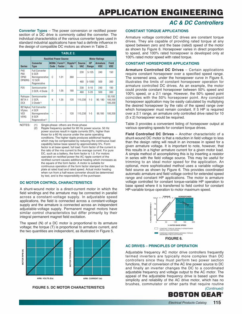
®
Electrical Products Catalog 115
APPLICATION ENGINEERINGAC & DC Controllers
TABLE 2.Rectified Power Source Motor Ratings
Converter NEMA Form(2) Ripple(2) Source HP Armature FieldSeries Type Code Factor Hz VAC Range VDC VDC
P40 Full Converter 230 5-125 240 150P60 6 SCRDP60 Nonregenerative C 1.01 360DP60RG 12 SCR 460 5-1000 500 300
Regenerative
P25 Semiconverter 230 5-10 240 1503 SCR, 4 Diode D 1.05 180 460 5-20 500 300
Ratiopax Semiconverter 50,100BETA II 2 SCR, K 1.35 120 115,230 1-3 90, 180 100,200DCX 3 Diode(1) 100,200
BETAplus Full ConverterVEplus 4 SCRVED Nonregenerative – – 120 115,230 1-5 90,180 100,200VERG 8 SCR
Regenerative(1)
NOTES: (1) Single-phase: others are three-phase(2) Ripple frequency quoted for 60 Hz power source. 50 Hz
power sources result in ripple currents 20%, higher thanthose for a 60 Hz source under the same operatingconditions. The higher ripple produces additional heatingwhich may be compensated by reducing the continuous loadcapability below base speed by approximately 5%. Formfactor is at base speed, full load. Form factor of the current isthe ratio of the rms current to the average current. For pureDC, such as a battery, the form factor is 1.0. For motorsoperated on rectified power the AC ripple content of therectified current causes additional heating which increases asthe square of the form factor. A motor is suitable forcontinuous operation of the form factor stamped on the dataplate at rated load and rated speed. Actual motor heatingwhen run from a half-wave converter should be determinedby test, and is the responsibility of the purchaser.
DC MOTOR CONTROL CHARACTERISTICSA shunt-wound motor is a direct-current motor in which thefield windings and the armature may be connected in parallelacross a constant-voltage supply. In adjustable speedapplications, the field is connected across a constant-voltagesupply and the armature is connected across an independentadjustable-voltage supply. Permanent magnet motors havesimilar control characteristics but differ primarily by theirintegral permanent magnet field excitation.The speed (N) of a DC motor is proportional to its armaturevoltage; the torque (T) is proportional to armature current, andthe two quantities are independent, as illustrated in Figure 5.
ARM. VOLTS (Ea) ARM. CURRENT (Ia)
MO
TOR
RP
M (
N)
MO
TOR
TO
RQ
UE
(T
)
FIGURE 5. DC MOTOR CHARACTERISTICS
Converter Types – The power conversion or rectified powersection of a DC drive is commonly called the converter. Theindividual characteristics of the various converter types used instandard industrial applications have had a definite influence inthe design of compatible DC motors as shown in Table 2.
CONSTANT TORQUE APPLICATIONSArmature voltage controlled DC drives are constant torquedrives. They are capable of providing rated torque at anyspeed between zero and the base (rated) speed of the motoras shown by Figure 6. Horsepower varies in direct proportionto speed, and 100% rated horsepower is developed only at100% rated motor speed with rated torque.CONSTANT HORSEPOWER APPLICATIONSArmature Controlled DC Drives – Certain applicationsrequire constant horsepower over a specified speed range.The screened area, under the horsepower curve in Figure 6,illustrates the limits of constant horsepower operation forarmature controlled DC drives. As an example, the motorcould provide constant horsepower between 50% speed and100% speed, or a 2:1 range. However, the 50% speed pointcoincides with the 50% horsepower point. Any constanthorsepower application may be easily calculated by multiplyingthe desired horsepower by the ratio of the speed range overwhich horsepower must remain constant. If 5 HP is requiredover a 2:1 range, an armature only controlled drive rated for 10(5 x 2) horsepower would be required.Table 3 provides a convenient listing of horsepower output atvarious operating speeds for constant torque drives.Field Controlled DC Drives – Another characteristic of ashunt-wound DC motor is that a reduction in field voltage to lessthan the design rating will result in an increase in speed for agiven armature voltage. It is important to note, however, thatthis results in a higher armature current for a given motor load.A simple method of accomplishing this is by inserting a resis torin series with the field voltage source. This may be useful fortrimming to an ideal motor speed for the application. Anoptional, more sophisticated method uses a variable voltagefield source as shown by Figure 6. This provides coordinatedauto matic armature and field voltage control for extended speedrange and constant HP applications. The motor is armaturevoltage controlled for constant torque-variable HP oper ation tobase speed where it is transferred to field control for constantHP-variable torque operation to motor maximum speed.
AC DRIVES – PRINCIPLES OF OPERATIONAdjustable frequency AC motor drive controllers frequentlytermed inverters are typically more complex than DCcontrollers since they must perform two power sectionfunctions, that of conversion of the AC line power source to DCand finally an inverter changes the DC to a coordinatedadjustable frequency and voltage output to the AC motor. Theappeal of the adjustable frequency drive is based upon thesimplicity and reliability of the AC drive motor, which has nobrushes, commutator or other parts that require routine
EP24
8A
CONSTANT TORQUE-VARIABLE HORSEPOWER(RATED FIELD EXCITATION)
CONSTANT HORSEPOWER-VARIABLE TORQUE(WEAKENED FIELD EXCITATION)
100
75
50
25
0 10050 150 200
TORQUE HORSEPOWER
TORQUE
HORSEPO
WER
% R
ATE
D H
OR
SE
PO
WE
R &
T
OR
QU
E
% RATED BASE SPEED
FIGURE 6.
(Continued)

®
116 Electrical Products Catalog
maintenance, which more than compensates for the complexity of the AC controller. The robust construction, andlow cost of the AC motor makes it very desirable for a widerange of uses. Also, the ability to make an existing standardconstant speed AC motor an adjustable speed device simplyby the addition of an adjustable frequency controller creates avery strong incentive for this type of drive.AC CONTROLLER TYPESA number of different types of AC motor controllers arecurrently in common use as general purpose drives: Six-Stepor Variable Voltage Input (VVI), Pulse Width Modulated(PWM), Current Source Input (CSI), and the LoadCommutated Inverter (LCI). Each type offers specific benefitsand characteristics but the Six-Step and PWM types havebeen selected by Boston Gear as offering the bestcombination of simplicity, performance and economy forgeneral purpose applications. Table 4 shows comparativeadvantages and disadvantages.
Six Step Controllers – Six-Step controllers, so called due totheir output voltage waveform, utilize an adjustable voltage,linkcoupled inverter system as shown in Figure 7.The controller converts the AC power source to an adjustableDC voltage proportional to the speed reference command.The DC voltage is smoothed by a filter network and directed toa six-step inverter. The inverter changes the DC to AC at afrequency proportional to the speed reference. Output voltageand frequency are simultaneously coordinated and regulatedto maintain a specific relationship of voltage and frequency(volts/Hz ratio) throughout the normal speed range. Thevoltage waveform applied to the motor is a stepped waveapproximation of a true sinusoidal waveform as shown byFigure 8. The low harmonic content of this waveform has littleadverse effect on the motor.
Rated HP Rated Torque HP Ratings at Various Motor RPMAt 1750 RPM At All SpeedsBase Speed Lb. -Ft. (1) 1575 1400 1225 1050 875 700 525 350 175 87.5 35
1/6 0.50 .150 .133 .117 .100 .083 .067 .050 .033 .017 .008 .0031/4 0.75 .225 .200 .175 .150 .125 .100 .075 .050 .025 .013 .0051/3 1.00 .300 .267 .233 .200 .167 .133 .100 .067 .033 .017 .0071/2 1.50 .450 .400 .350 .300 .250 .200 .150 .100 .050 .025 .0103/4 2.25 .675 .600 .525 .450 .375 .300 .225 .150 .075 .038 .0151 3.00 .900 .800 .700 .600 .500 .400 .300 .200 .100 .050 .020
1-1/2 4.50 1.350 1.200 1.050 .900 .750 .600 .450 .300 .150 .075 .0302 6.00 1.800 1.600 1.400 1.200 1.000 .800 .600 .400 .200 .100 .0403 9.00 2.700 2.400 2.100 1.800 1.500 1.200 .900 .600 .300 .150 .0605 15.00 4.500 4.000 3.500 3.000 2.500 2.000 1.500 1.000 .500 .250 .100
7-1/2 22.50 6.750 6.000 5.250 4.500 3.750 3.000 2.250 1.500 .750 .375 .15010 30.00 9.000 8.000 7.000 6.000 5.000 4.000 3.000 2.000 1.000 .500 .20015 45.00 13.500 12.000 10.500 9.000 7.500 6.000 4.500 3.000 1.500 .750 .30020 60.00 18.000 16.000 14.000 12.000 10.000 8.000 6.000 4.000 2.000 1.000 .40025 75.00 22.500 20.000 17.500 15.000 12.500 10.000 7.500 5.000 2.500 1.250 .50030 90.00 27.000 24.000 21.000 18.000 15.000 12.000 9.000 6.000 3.000 1.500 .60040 120.00 36.000 32.000 28.000 24.000 20.000 16.000 12.000 8.000 4.000 2.000 .80050 150.00 45.000 40.000 35.000 30.000 25.000 20.000 15.000 10.000 5.000 2.500 1.00060 180.00 54.000 48.000 42.000 36.000 30.000 24.000 18.000 12.000 6.000 3.000 1.20075 225.00 67.500 60,000 52.500 45.000 37.000 30.000 22.500 15.000 7.500 3.750 1.500100 300.00 90.000 80.000 70.000 60.000 50.000 40.000 30.000 20.000 10.000 5.000 2.00125 375.00 112.500 100.000 87.500 75.000 62.500 50.000 37.500 25.000 12.500 6.250 2.50
Percent of Base Speed 90 80 70 60 50 40 30 20 10 5 2
TABLE 3. HORSEPOWER OUTPUT AT VARIOUS MOTOR SPEEDS WITH 1750 RPM BASE SPEED CONSTANT TORQUE DRIVES
Motors may require supplemental cooling when operated continuously at ratedload at reduced speeds. See Motor Specifications.NOTE: (1) lb-in = lb - ft × 12
(1) Torque ratings for other base speed motors:2500 RPM Motor = 1750 RPM Torque x .7 Approx.1150 RPM Motor = 1750 RPM Torque x 1.52 Approx.850 RPM Motor = 1750 RPM Torque x 2.06 Approx.
EP23
4A
POWERSOURCE1-Ø 50 or
60 Hz
LINEINDUCTORS
ADJUSTABLEVOLTAGE
BUS
FILTERNETWORK
SPEED REFERENCE
FREQUENCY
(1) 120 Hz BY SELECTOR SWITCH
CURRENTFEEDBACK
FAULTLIMITINGFACTOR
3Ø OUTPUT0-60 Hz AC
MOTORDC
CONVERTER
DCCONTROLCIRCUITS
INVERTER
ACCONTROLCIRCUITS
EP23
5A
LINE-TO-NEUTRALVOLTAGE
LINECURRENT
TYPICAL VOLTAGE AND CURRENT WAVE FORMSFOR A VVI CONTROLLER
FIGURE 7.FIGURE 8.
APPLICATION ENGINEERINGAC & DC Controllers

®
Electrical Products Catalog 117
APPLICATION ENGINEERINGAC & DC Controllers
Type
PWM
Six-Step
PWM Controllers–The PWM controller converts the AC powersource to a fixed DC voltage by a full-wave rectifier. The resul -tant DC voltage is smoothed by a filter network and applied toa pulse width modulated inverter using high power transistors.These transistors are normally Darlington, MOSFET (MetalOxide Semiconductor Field Effect Transistor) or IGBT(Insulated Gate Bipolar Transistor) types. The MOSFET andIGBT types allow higher switching frequencies and therefore,less audible motor noise. The speed reference command isdirected to the microprocessor which simul ta ne ously optimizesthe carrier (chopping) frequency and inverter out put frequencyto maintain a proper volts/Hz ratio and high effi ciencythroughout the normal speed range. See Block Diagram,Figure 9.The voltage applied to the motor is a pulsed approximation of atrue sinusoidal waveform as shown in Figure 10. This is
commonly called a PWM waveform because both the carrierfrequency and pulse-width is changed (modulated) to changethe effective voltage amplitude and frequency. The currentwaveform very closely follows the shape of a sine wave andtherefore provides improved low speed motor performance,efficiency, and minimizes motor heating.
AC MOTOR CONTROL CHARACTERISTICSThe synchronous speed of an AC induction motor is directlyproportional to the applied frequency.
The synchronous speed is the speed of the rotating electricalfield, not the actual motor rotor speed. The difference betweenthe synchronous speed and the full-load motor speed is calledslip, which is normally expressed in percent. The percentage ofslip is determined by the design of the motor, primarily the rotorresistance. NEMA has assigned code letters (A, B, C, D, etc.)to standardize motor characteristics including slip. The typemost commonly used is NEMA Design B with 3% slip at ratedoperating conditions. Figure 11 shows typical speed/torquecurves for NEMA Design B and D motors.
As the applied frequency ischanged, the motor will runfaster or slower as shownby Figure 12. The actualfull-load motor slip (as apercent of the motorsynchronous speed) variesin inverse proportion to thefrequency, where a 3% slipmotor 60 Hz would have a6% slip at 30 Hz or 1 1/2 %slip at 120 Hz. Motor speedis limited only by themaximum inverter output frequency, load torque requirements,and the mechanical integrity of the motor.
EP23
6A
6 DIODEFULL-WAVE
BRIDGE
PWMINVERTER
CONTROLCIRCUITS
POWERSOURCE1-PHASE
OR 3-PHASE
FILTERNETWORK
DC CURRENTFEEDBACK
CONTROL
SPEEDREFERENCE
3-PHASE OUTPUT0-MAX HZ
ACMOTOR
TRANSISTEROVER CURRENT
FEEDBACK
FIGURE 9.
TABLE 4. COMPARISON OF PWM VERSUS SIX-STEPADJUSTABLE FREQUENCY AC CONTROLLER CAPABILITIES
Advantages• Microprocessor based
PWM units are typicallyless expensive than six-step units which commonlyuse SCR phase convertersand analog techniques.
• 30:1 and greater, constanttorque speed range withsmooth, noncogging lowspeed operation.
• High Power Factor–Displacement power fac toris 96% or better over entirespeed range at rated load.
• High Efficiency – Controlleronly 96%. Complete drivepowered by a 3-phasesource 83%, 70-80% whenpowered from a single-phase source, dependentupon motor efficiency.
• Power section with simplediode bridge AC to DC frontend converter.
• Diode converter causes noline notching.
• Complex microprocessorcircuitry easily serviced bysubstitution.
• Quiet motor operation withminimal audible noise.
• Radiated RFI well withinF.C.C. guidelines (non-microprocessor designs)making them desirable forsensitive applications suchas hospitals.
• Minimal distortion of the ACvoltage source with phasecontrol input designs.
• Power factor 95% or less,variable with speed andload.
Disadvantages• Audible motor noise may
be objectionable for someapplications. This can beminimized/eliminated withhigher carrier frequencies,but this reduces controllerefficiency (IGBT units allowhigher switching frequen -cies, therefore less audiblemotor noise).
• Microprocessor controlcom mon to PWM invertersand high frequency poweroutput tends to produceradiated, radio frequencyinterference (RFI) whichmay be objectionable insensitive environmentssuch as hospitals, com -munications centers, etc.
• Up to 2.5 times greaterdistortion of the AC voltagesource than phase control input six step drives.
• Speed range limited to 10:1constant torque. Ratedtorque operation producesmotor cogging at and belowthis speed.
• Phase controlled convertermay produce notches in theAC line power source.
• Power factor reduces withspeed and load.
• SCR phase converters andanalog circuitry common tothese units usually makethem more expensive thanPWM designs.
EP40
7A
LINE-TO-NEUTRALVOLTAGE
LINECURRENT
TYPICAL PWM VOLTAGE ANDCURRENT WAVEFORMS
FIGURE 10.
BREAKDOWN LANE
NEMADESIGN D
NEMADESIGN B
8-13% SLIP TYP.3% SLIP TYP.
% FULL-LOAD TORQUE
% S
YN
CH
RO
NO
US
SP
EE
D
100
75
50
25
0 100 150 200 300
FIGURE 11.
FIGURE 12. TYPICAL SPEEDTORQUE CURVES FOR 60 HZNEMA DESIGN B MOTOR
(WITHOUT VOLTAGE BOOST)
60
50
40
30
20
10
0 50
50
100 150 200
25
75
100
% RATED TORQUE
FREQ
UENC
Y (H
ertz
)
% SYNCHRO
NOUS SPEED

®
118 Electrical Products Catalog
MOTOR SELECTIONConstant Torque Applications–About 90% of all generalindustrial machines, other than fans and pumps, are constanttorque systems where the machine’s torque requirement isindependent of its speed. If the machine speed is doubled, itshorsepower requirement doubles. Conversely a reduction inmachine speed by 50% will result in an equal reduction inhorsepower, but no reduction in torque.1. Standard three-phase AC motors, designed for fixed speed
operation at standard line frequency, may be easily adaptedfor use with the AC controller by considering the following:a. A slight increase in motor losses occurs with inverter
power.b. The motor thermal capacity
must typically be derated asa function of the minimum,continuous operating speedin accord with Figure 13, dueto the reduced venti la tionprovided by the integralmotor fan. Where the appli -ca tion requires 100% ratedtorque at speeds below 50%of synchronous speed, aseparately powered ventila -tion blower, a nonventilatedmotor with greater reserve thermal capacity or, a motorwith higher rated capacity should be used. When aseparately powered ventilation blower is used, athermostat should be built into the motor to preventdamage which may result from a failure in the ventilationsystem.
2. Any three-phase synchronous or induction AC motordesigned expressly for adjustable speed service by invertercontrol may normally be used over its design speed rangewith the AC controller.
Variable Torque Applications–The application of standard ACmotors to adjustable speedvariable torque applications suchas centrifugal fans or pumps isideal from a motor cooling stand -point. The torque character istics ofa variable torque (cubed expo -nential horsepower) load are suchthat the load falls off rapidly as themotor speed is reduced. Thevariable torque load elimi nates thenecessity to derate the motor dueto excessive heat resulting fromdiminished motor cooling at reduced speeds. Figure 14illustrates the relationship between speed and torque invariable torque applications.Potential Power Savings–Mostfan and pump applications requirethe system to run for sustainedperiods at reduced outputs byeither reducing the speed of themotor or by mechanically alteringthe flow. Figure 15 illustrates typicalenergy savings, in percent of ratedpower, which can be realized whenusing an adjustable frequency
controller to reduce motor speed and thereby system flow asopposed to a constant speed motor which has its system flowvaried by an outlet damper.Constant Torque Operation–The ability of the AC controller tomaintain a constant volts/Hzrelationship is ideal from a motorstandpoint. This permits operationof the motor at rated torque fromnear standstill to rated speed.Figure 16 represents the rela tion -ship between torque, horsepowerand motor speed with a main tainedvolts/Hz ratio using a 60 Hz controller for illustration. Astandard 4-pole 460V motor can be controlled by this methodto its synchronous speed of 1800 RPM. If the same motor werewound for 50% of the input voltage (230V), it could becontrolled with constant torque to double the normal ratedspeed and horsepower. The motor would not be “overvoltaged”because the volts/Hz ratio could be maintained e.g.: a motorwound for 230 VAC can supply constant torque to twice the ACline frequency when used on a 460V power source withoutovervoltaging the motor because the volts/Hz ratio of 230V/60Hz is the same as 460V/120 Hz. The horsepower would alsodouble since the same torque would be developed at twice thenormal rated speed.Caution must be observed when applying standard motors forcontinuous low speed, rated torque operation. The motor’s self-cooling capability is dependent upon self-ventilation schemeswith efficiency that is considerably reduced at lower operatingspeeds.Constant Horsepower Oper-ation – AC motor controllers arealso adaptable to constanthorsepower operation as shownby Figure 17. With this mode ofoperation, the volts/Hz ratio ismaintained to a specific frequency,normally 50 or 60 Hz. At this point,the voltage is “clamped” at aconstant level while the frequencyis adjusted further to achieve thedesired maximum speed. Sincethe controller maximum output voltage is limited to the voltageof the AC power source, the volts/Hz ratio must decreasebeyond this point as the frequency increases. The motorbecomes “voltage starved” above the clamping point andtorque decreases as speed increases, resulting in constanthorsepower output.As shown in Figure 17 the drive provides conventional constanttorque/variable horsepower operation up to 60 Hz which isequivalent to the 1800 RPM base speed of the 60 Hz motor.Between 1800 and 3600 RPM, the drive provides constanthorsepower/variable torque operation. If constant horsepoweris required between 900 and 3600 RPM (a 4:1 speed range) –using the same 1800 RPM base speed motor, the drive ratedhorsepower must be increased since 900 RPM intersects thecurve at a point which is 50% of rated horsepower.Constant HP operation (above synchronous speed) is limitedto induction motors only. In addition, at some point, typicallyaround three times base speed for a four-pole induction motor,the breakdown torque of the motor prevents further constanthorsepower operation. Synchronous reluctance motorcharacteristics prevent operation in this mode.
CONTINUOUSDUTY
INTERMITTENTDUTY
0 25 50 75 100
25
50
75
100
% RATED TORQUE
% R
ATED
SPE
ED
FIGURE 13. TYPICALSTANDARD AC MOTORSADJUSTABLE SPEED
OPERATION
900 1800 2700 3600
100
MOTOR RPM (4-POLE MOTOR)
% R
ATED
T
ORQ
UE O
R
200
0
30 60 90 1200
TORQUE
HP
460V MOTOR-CONSTANT VOLTS Hz RATIO
230V MOTOR-CONSTANT VOLTS Hz RATIO
FREQUENCY Hz
FIGURE 16. CONSTANTTORQUE OPERATION
900 1800 2700 3600
50
MOTOR RPM (4-POLE, 230V, 80HZ. MOTOR)
PERC
ENT
RATE
DHP
AND
T
100
0
30 60 90 1200
TORQUE
HP
75
25
0
FREQUENCY Hz
FIGURE 17. TYPICALCONSTANT HPOPERATION
CONTINUOUSDUTY
INTERMITTENTDUTY
0 25 50 75 100
25
50
75
100
% RATED TORQUE
% R
ATED
SPE
ED
TYPICALPUMP/FAN
LOAD
FIGURE 14. TYPICALSTANDARD AC MOTORAPPLICATION WITHVARIABLE TORQUE
LOADS
OUTPUT DAMPER
20 40 60 80
20
40
60
80
RATED FLOW (SPEED) – %
% IN
PUT
POW
ER
ENERGY SAVINGS
100
100
ADJUSTABLE FREQUENCYAC DRIVE
FIGURE. 15.ENERGY SAVINGS
APPLICATION ENGINEERINGAC & DC Controllers

®
Electrical Products Catalog 119
APPLICATION ENGINEERINGAC & DC Controllers
Multiple Motor Operation (From a Common Controller) –An adjustable frequency AC motor controller is ideally suitedfor simultaneous control of multiple motors in process lineappli ca tions. All motors are operated at a common frequencyand are therefore synchronized at a common speed. Trackingaccuracy between the individual motors varies only the dif fer -ence in their loads, typically 0.5% to 3% with standard NEMADesign B motors and 0.0% with synchronous reluctancetypes.Where tracking ratios other than 1:1 are desirable, gearboxes, fixed or adjustable sheaves may be used to attain thedesired individual speeds. Two-pole, four-pole and six-polemotors may also be mixed to obtain various individual motoroperating speeds when operated from a common adjustablefrequency controller. Selection of a properly rated controllershould be made with consideration for the total KVA requiredby all the motors which are normally started and stoppedsimultaneously. Some process line applications require theability to selectively start and stop one or more of the motorswhile the others are operated at the desired speed. Astandard motor started under this condition instantaneouslydraws locked-rotor current of 600-800%. Unless this factor isconsidered in the selection of an adequately rated controller,the additional load may exceed the capacity of the power unit,reducing the voltage to the entire system which could causethe line to stall or trip off.AC VS. DC DRIVE COMPARISONAC and DC drives both continue to offer unique benefits andfeatures that may make one type or other better suited forcertain applications.AC drives may be better because . . .
• They use conventional, low cost, 3-phase AC inductionmotors for most applications.
• AC motors require virtually no maintenance and arepreferred for applications where the motor is mounted inan area not easily reached for servicing or replacement.
• AC motors are smaller, lighter, more commonly available,and less expensive than DC motors.
• AC motors are better suited for high speed operation(over 2500 rpm) since there are no brushes, andcommutation is not a problem.
• Whenever the operating environment is wet, corrosive orexplosive and special motor enclosures are required.Special AC motor enclosure types are more readilyavailable at lower prices.
• When multiple motors in a system must operatesimultaneously at a common frequency/speed.
• When it is desirable to use an existing constant speed ACmotor already mounted and wired on a machine.
• When the application load varies greatly and light loadsmay be encountered for prolonged periods. DC motorcommutators and brushes may wear rapidly under thiscondition.
• When low cost electronic motor reversing is required.• Whenever it is important to have a back up (constant
speed) if the controller should fail.
DC drives may be better because . . .• DC drives are less complex with a single power
conversion from AC to DC.• DC drives are normally less expensive for most
horsepower ratings.• DC motors have a long tradition of use as adjustable
speed machines and a wide range of options haveevolved for this purpose:
• Cooling blowers and inlet air flanges provide cooling airfor a wide speed range at constant torque.
• Accessory mounting flanges and kits for mountingfeedback tachometers and encoders.
• DC regenerative drives are available for applicationsrequiring continuous regeneration for overhauling loads.AC drives with this capability would be more complex andexpensive.
• When properly applied brush and commutatormaintenance is minimal.
• DC motors are capable of providing starting andaccelerating torques in excess of 400% of rated.
• Some AC drives may produce audible motor noise whichis undesirable in some applications.
• DC SCR drives have been the first choice of industry forover 25 years. Their maintenance, technology,serviceability and reliability are well understood by plantmaintenance personnel.
BASIC MECHANICSThe curve in Figure 6 shows a distinct relationship betweenspeed, torque and horsepower. Torque is constant at anyspeed while there is a direct proportional relationship betweenhorse power and speed; horsepower varies directly with thespeed. Therefore, horsepower is motion dependent, torque is not.TORQUEA force applied in a manner that tends to produce rotation,such as a pipe wrench on a shaft. Torque (force) withoutrotation is termed static torque, since no motion is produced.
Torque is measured in lb-inor lb-ft which is the productof the force in pounds (lb) xthe distance in inches (in)or feet (ft) from the centerof the point of apparentrotation. Figure 18 shows120 lb-in (12 inches x 10lbs) or 10 lb-ft torque.
Because most power transmission is based upon rotatingelements, torque is important as a measurement of the effortrequired to produce work (horsepower).POWER (Horsepower)A force applied in a manner that produces motion and,therefore, work over a specified time period. A common unit ofpower is horsepower. One horsepower (HP) is defined asthe force required to lift 33,000 lbs, one foot in oneminute.
12" R
FORCE 10 LBS.
EP07
1A
FIGURE 18

®
120 Electrical Products Catalog
Machine Types Breakaway Torque* Drive SelectionMachines with ball 110 to 125% Standard drive ratingor roller bearingsMachines with 130 to 150% Standard drive ratingsleeve bearingsConveyors andmachines with 160 to 250% Oversize driveexcessive slidingfrictionMachines that have"high" load spots intheir cycle, e.g.,printing and punch 250% to 600% Oversize drivepresses, andmachines with camor crank operatedmechanismsHigh Inertia – Machines with fly-wheels or other Nominal rating of Drive rating depen-heavy rotating drive will depend dent upon desiredmasses. Also, some on the breakaway acceleration timemachines that move torque requirement and drive torquelarge masses bycranks, centrifuges,etc.
HORSEPOWER-TORQUE,GETTING IT TOGETHERAs shown in Figure 19, the50 lb load is acting on the 5inch radius (distance) of thewinch, producing a loadtorque of 250 lb-in (50 lbs ×5 inches) that must beovercome to lift the load.Since the hand crank armhas a 10 inch radius(distance), a minimum force of 25 lbs must be exerted toovercome the load torque (25 lbs × 10" = 250 lb-in). If nomotion is involved, the system is in balance. Although torque isbeing exerted, no work is accomplished and no horsepower isdeveloped.The winch diameter is 10 inches. Therefore, each revolution ofthe hand crank will lift the weight 10 inches x π = 31.416inches (2.618 feet).If the crank is turned at 10 RPM, 50 lbs will be lifted a distanceof 26.18 feet in one minute:
Turning the crank twice as fast (20 RPM) will develop twice thehorsepower.
Thus, the horsepower of rotating elements can be calculatedfrom the following formula:
Where,F = force in poundsR = radius (lever length in feet)
RPM or N = revolutions per minuteT = torque in lb-ft (F x R)
SELECTING A DRIVE FOR A MACHINEThe application of an adjustable speed drive to power amachine is a mechanical, rather than an electrical problem.When applying the drive, the speed – torque – horsepowercharacteristics developed at the drive motor shaft must beconsidered, and how well these characteristics suit themachine.Four essential parameters are1. Breakaway Torque2. Process Torque3. Accelerating Torque4. Running Torque
BREAKAWAY TORQUE –The torque required to start the machine in motion.It is most always greater than the torque required to maintainmotion (running torque). Breakaway torque combined withprocess torque frequently determines drive selection. Table 5lists typical breakaway torques for various machine types.
*Typical percentages of running torque
PROCESS TORQUE –The torque required to pull, push, compress, stretch orotherwise process or act upon the material being transportedby or through the machine.On some machines, process torque may be so significant as todetermine the drive power rating. On other machines, this loadmay be insignificant. The process torque load is superimposedon all other static and dynamic torque requirements of themachine.
10"
25LBS.
50LBS.
10"DIA.
EP07
2A
Factor UnitDistance (Radius) Foot (or inches)Force (Push or Pull) PoundsTime One (1) Minute
THREE BASIC FACTORS ARE INVOLVED:
TABLE 5. TYPICAL BREAKAWAY TORQUES FOR VARIOUS MACHINE TYPES
FIGURE 19
APPLICATION ENGINEERINGAC & DC Controllers
F (Load in Pounds) x Feet per Minute33,000HP =
(Load in Pounds) x Feet per Minute33,000HP =
50 x 26.1833,000HP = = .03966 HP
50 x 52.3633,000HP = = .07933 HP
F x 2π x R x RPM T x RPM 33,000 5252HP = =

®
Electrical Products Catalog 121
APPLICATION ENGINEERINGAC & DC Controllers
ACCELERATING TORQUE –The torque required to bring the machine to an operatingspeed within a given time.With most machines, the load is largely friction and a standarddrive rating may have adequate torque for satisfactoryacceleration. However, certain machines classified as "highinertia" with flywheels, bull gears or other large rotatingmasses may require drive selection based upon the powerrequired to accelerate the load within a given time.RUNNING TORQUE –The torque required to maintain machine motion after itaccelerates to the desired operating speed.The characteristics of the speed-torque curves of variousmachines are very important to proper adjustable speed driveselection. Most machines fall into four basic categories:1. Constant Torque (Figure 20)2. Constant Horsepower (Figure 21)3. Squared Exponential Horsepower (Figure 22)4. Cubed Exponential Horsepower (Figure 23)
Some machines may have operating characteristics which area composite of the basic types.
Figure 20. Constant Torque Figure 21. ConstantHorsepower
Figure 22. Squared Figure 23. CubedExponential Horsepower Exponential Horsepower
– – – – Torque _______ HP
CONSTANT TORQUE –Most industrial machine applications, other than pumps, areconstant torque systems.The machine's torque requirement is independent of its speed.If the machine speed is doubled, its horsepower requirementdoubles. This fact must be kept in mind when replacing aconstant speed drive with an adjustable speed drive and themachine operating speed is increased.CONSTANT HORSEPOWER –For machines with constant horsepower loads, the powerdemand is independent of speed, and torque varies inverselywith speed.
This type is most often found in the machine-tool industry andwith center driven winders. When drilling, shaping, milling, orturning metal, the loads all tend toward constant horsepower.At low speed there is high torque; at high speed, light torque.A drive must be selected for its highest torque condition whichis at the lowest speed of the range. With most machines, the"constant horsepower range" seldom exceeds a 3:1 range.SQUARED-EXPONENTIAL LOADS –With machines of this type, torque varies directly as thespeed, and power as the square of speed.Such relationships are frequently found in positive-displacement pumps and mixer applications.CUBED-EXPONENTIAL LOADS –It is characteristic of these machines that torque varies as thesquare of speed, and power as the cube of speed.This type of load is imposed on centrifugal pump drives andmost fan or blower drives. In some uses, fan or blowerhorsepower varies as the fifth power of speed. Theexponential relationship is characteristic of these machines.This fact must be considered when sizing motors foradjustable speed drives. If the speed of a centrifugal pump isdoubled, its power requirement increases by a factor of eight.OTHER APPLICATION FACTORSCONSTANT TORQUE SPEED RANGE –On large motors, minimum operating speed limitations may benecessary for self-ventilated motors, since their cooling isentirely dependent upon motor speed and, therefore,diminishes as speed is reduced. Where rated torque operationis required continuously at lower speeds, either a higher rateddrive motor or supplemental motor ventilation, such as a motormounted cooling blower or external air duct, is required.TORQUE LIMITATIONS –Most adjustable speed drives feature a torque limiter to protectthe drive and the machine from torque overloads. The torquelimiter (current limit) is normally adjusted to 150% of ratedtorque to allow extra momentary torque for breakaway,acceleration or cyclic overloads. Most drive systems arecapable of sustaining the 150% torque overload for oneminute or less.DUTY CYCLE –Certain applications may require continuous reversals, longacceleration times at high torque due to inertia loads, frequenthigh rate acceleration, or cyclic overloads which may result insevere motor heating if not considered in the selection of thedrive. Most drives with 150% overload capability will operatesuccessfully if there are compensating periods of operationwhere motor temperatures can be normalized.MEASURING MACHINE TORQUETo measure the torque required to drive a machine, fasten apulley securely to the shaft which the motor is to drive. Fastenone end of a cord to the outer surface of the pulley and wrap afew turns of the cord around the pulley. Tie the other end ofthe cord to a spring scale. See Figure 24.
0 50 100 1500
50
100
150
% SPEED
% T
ORQ
UE A
ND H
P
0 50 100 1500
50
100
150
% SPEED
% T
ORQ
UE A
ND H
P
0 50 100 1500
50
100
150
% SPEED
% T
ORQ
UE A
ND H
P
EP07
3A
0 50 100 1500
50
100
150
% SPEED
% T
ORQ
UE A
ND H
P

®
122 Electrical Products Catalog
Figure 24.Pull on scale until the shaft turns. The force in pounds orounces, indicated on the scale, multiplied by the radius of thepulley (measured from the centerline of the machine shaft) ininches gives the torque value in lb-inches or oz-inches. Onsome machines, this torque may vary as the shaft rotates. Thehighest value of torque must be used when selecting a motor.The running torque required by a machine will beapproximately equal to the starting torque if the load iscomposed almost entirely of friction. If the load is primarilyinertia or windage, the characteristics of the inertia or windageproducing elements must be determined.The running torque of a machine can be accuratelydetermined by making a test run with an armature controlledDC drive (with a shunt wound or permanent magnet DCmotor) of known horsepower rating. The DC drive should havean ammeter in the armature circuit so significant currentreadings can be observed and recorded throughout the speedrange of the machine. Since armature current and torque aredirectly proportional within very close limits, the currentreadings will provide accurate information for selecting thedrive rating required by the machine.Most machines require a higher torque value for breakaway,but once running, the torque requirement will decrease. Manydrives have 150% load capability for one minute, which mayallow the required additional breakaway torque to be obtainedwithout increasing the drive horsepower rating.If the running torque is equal to or less than the breakawaytorque divided by 1.5, use the breakaway torque divided by1.5 as the full-load torque required to determine the motorhorsepower.If the running torque is greater than the breakaway torquedivided by 1.5, but less than the breakaway torque, use therunning torque as the full load rated torque required todetermine the motor horsepower.MECHANICAL FORMULASHOW TO CALCULATE TORQUEIf the horsepower and base speed of a motor are known, thefull-load torque of the motor is determined by:
Where, T = Torque (lb-ft)HP = Horsepower
N = Base speed of motor (RPM)
HOW TO CALCULATE HORSEPOWERFor Rotating Objects:
Where, T = Torque (lb-in)N = Speed (RPM)
or:Where, T = Torque (lb-ft)
N = Speed (RPM)For Objects in Linear Motion:
Where, F = Force (lb)V = Velocity (IPM)
or:Where, F = Force (lb)
V = Velocity (FPM)For Pumps:
For Fans and Blowers:
When calculated horsepower falls between standard motorratings, select the next higher rating.CALCULATING ACCELERATING FORCE FOR LINEARMOTION.The following formula can be used to calculate theapproximate accelerating force required for linear motion.However, before sizing the drive, add the torque required toaccelerate the motor armature, gears, pulleys, etc. to thelinear-motion accelerating force converting to torque.
Where, W = Weight (lb)∆V = Change in velocity (FPM)
t = Time (seconds) to accelerate weightCALCULATING ACCELERATING TORQUE FOR ROTARYMOTIONWhen, in addition to the selection of a motor with propertorque capacity to start and maintain machine motion, adesired time for acceleration is involved and the requiredtorque value may be affected, an additional formula must beconsidered. This formula makes it possible to calculate theaverage torque required over the complete range of speedchange to accelerate a known inertia (WK2).On high inertia loads, accelerating torque may be the majorfactor in the drive selection.
R PULLEY
SCALE
F
TORQUE = F X R
EP07
4A
APPLICATION ENGINEERINGAC & DC Controllers
(5250) (HP)NT =
TN63,025HP =
TN5250HP =
FV396,000HP =
FV33,000HP =
(GPM) x (Head in Feet) x (Specific Gravity)3950 x (Efficiency of Pump)
HP =
CFM x (Pressure in Pounds/Sq ft)33,000 x Efficiency
HP =
W (∆V)1933tAcceleration Force (F) =

®
Electrical Products Catalog 123
APPLICATION ENGINEERINGAC & DC Controllers
The formula to calculate acceleration torque (torque requiredabove load torque) or a rotating member:
Where, T = Acceleration torque (lb-ft)WK2=Total system inertia (lb-ft2) that the motor
must accelerate. This value includesmotor armature, reducer and load.
∆N = Change in speed required (RPM)t = Time to accelerate total system load
(seconds)The same formula can also be used to determine the minimumacceleration time of a given drive, or if it can accomplish thedesired change in speed within the required time period.
INERTIA (WK2)The factor WK2 is the weight (lbs)of an object multiplied by the square of the radius ofgyration (K). The unit measure -ment of the radius of gyration isexpressed in feet.For solid or hollow cylinders,inertia may be calculated by theequa tions shown in Figure 25.WK2 = lb-ft2
D, D1, D2 and L = in.ρ = lb./in.3
ρ (aluminum) = .0924ρ (bronze) = .320ρ (cast iron) = .260ρ (steel) = .282The inertia of solid steel shafting per inch of shaft length isgiven in Table 6. To calculate for hollow shafts, take thedifference between the inertia values for the O.D. and I.D. asthe value per inch. For shafts of materials other than steel,multiply the value for steel by the factors in Table 7.
For a solid cylinder or disc =
where r = radius in feet and W is weight in pounds.
where r1, is and r2 is .
The inertia of complex concentric rotating parts is calculatedby breaking the part up into simple rotating cylinders,calculating their inertia and summing their values, as shown inFigure 26.
FIGURE 26.
D
D2
D1
L
L
HOLLOW
SOLID
EP07
5A
WK2=.000681 ρLD4
WK2=.000681 ρL (D24-D1
4 )
Diam. (IN.) WK2 (lb Ft2) Diam. (IN.) WK2 (lb Ft2)3/4 0.00006 10-1/2 2.351 0.0002 10-3/4 2.581-1/4 0.0005 11 2.831-1/2 0.001 11-1/4 3.091-3/4 0.002 11-1/2 3.382 0.003 11-3/4 3.682-1/4 0.005 12 4.002-1/2 0.008 12-1/4 4.352-3/4 0.011 12-1/2 4.723 0.016 12-3/4 5.113-1/2 0.029 13 5.583-3/4 0.038 13-1/4 5.964 0.049 13-1/2 6.424-1/4 0.063 13-3/4 6.914-1/2 0.079 14 7.425 0.120 14-1/4 7.975-1/2 0.177 14-1/2 8.546 0.250 14-3/4 9.156-1/4 0.296 15 9.756-1/2 0.345 16 12.596-3/4 0.402 17 16.047 0.464 18 20.167-1/4 0.535 19 25.037-1/2 0.611 20 30.727-3/4 0.699 21 37.358 0.791 22 44.998-1/4 0.895 23 53.748-1/2 1.00 24 63.718-3/4 1.13 25 75.029 1.27 26 87.769-1/4 1.41 27 102.069-1/2 1.55 28 118.049-3/4 1.75 29 135.83
10 1.93 30 155.5510-1/4 2.13 — —
FORMULAS TO APPROXIMATE WK2
SHAFT MATERIAL FACTORRubber .121Nylon .181Aluminum .348Bronze 1.135Cast Iron .922
= +
EP07
6A
+
(1)
WK2= WK12 + WK2
2 +WK32
(2) (3)
TABLE 6. INERTIA OF STEEL SHAFTING(PER INCH OF LENGTH)
TABLE 7.
FIGURE 25.
(WK2) (∆N)308t
T =
(WK2) (∆N)308T
t =
r2W x2
r2 + r22For a hollow cylinder: W K2 = W x 2
ID2
OD2

®
124 Electrical Products Catalog
WK2 OF ROTATING ELEMENTSIn practical mechanical systems, all the rotating parts do notoperate at the same speed. The WK2 of all moving partsoperating at each speed must be reduced to an equivalentWK2 at the motor shaft, so that they can all be added togetherand treated as a unit, as follows:
Where, WK2=Inertia of the moving partN = Speed of the moving part (RPM)
NM=Speed of the driving motor (RPM)
When using speed reducers, and the machine inertia isreflected back to the motor shaft, the equivalent inertia isequal to the machine inertia divided by the square of the drivereduction ratio.
WK2 OF LINEAR MOTIONNot all driven systems involve rotating motion. The equivalentWK2 of linearly moving parts can also be reduced to the motorshaft speed as follows:
Where, W = Weight of load (lbs)V = Linear velocity of rack and load or conveyor
and load (FPM)NM=Speed of the driving motor (RPM)
NOTE: This equation can only be used where the linearspeed bears a continuous fixed relationship to themotor speed, such as a conveyor.
ELECTRICAL FORMULASOHMS Law:
POWER IN DC CIRCUITS:Watts = Volts × Amperes
POWER IN AC CIRCUITS:
124 Electrical Products Catalog
WK2 OF ROTATING ELEMENTSIn practical mechanical systems, all the rotating parts do notoperate at the same speed. The WK2 of all moving partsoperating at each speed must be reduced to an equivalentWK2 at the motor shaft, so that they can all be added togetherand treated as a unit, as follows:
Where, WK2 = Inertia of the moving partN = Speed of the moving part (RPM)
NM = Speed of the driving motor (RPM)
When using speed reducers, and the machine inertia isreflected back to the motor shaft, the equivalent inertia isequal to the machine inertia divided by the square of the drive
reduction ratio.
WK2 OF LINEAR MOTIONNot all driven systems involve rotating motion. The equivalentWK2 of linearly moving parts can also be reduced to the motor
shaft speed as follows:Where, W = Weight of load (lbs)
V = Linear velocity of rack and load or conveyorand load (FPM)
NM = Speed of the driving motor (RPM)
NOTE: This equation can only be used where the linearspeed bears a continuous fixed relationship to themotor speed, such as a conveyor.
ELECTRICAL FORMULASOHMS Law:
Volts = Amperes × Ohms
POWER IN DC CIRCUITS:Watts = Volts × Amperes
POWER IN AC CIRCUITS:
Horsepower = Volts × Amperes746
Kilowatts = Volts × Amperes1000
Kilowatt-Hours = Volts × Amperes × Hours1000
× Amperes1000
× Amperes × Power Factor1000
× Amperes × Power Factor × 1.421000
× Amperes × Power Factor × 1.731000
× Amperes
× Amperes × 1.731000
CONVERSION FACTORS
MULTIPLY BY TO OBTAINMeters 3.281 FeetMeters 39.37 Inches
Length Inches .0254 MetersFeet .3048 MetersMillimeters .0394 InchesNewton-Meters .7376 Lb-Ft
Torque Lb-Ft 1.3558 Newton-MeterLb-In .0833 Lb-FtLb-Ft 12.00 Lb-InRPM 6.00 Degrees/Sec.
Rotation RPM .1047 Rad./Sec.Degrees/Sec. .1667 RPMRad./Sec. 9.549 RPMNewton-Meters2 2.42 Lb-Ft2
Moment Oz-In2 .000434 Lb-Ft2of Lb-In2 .00694 Lb-Ft2
Inertia Slug-Ft2 32.17 Lb-Ft2Oz-In-Sec2 .1675 Lb-Ft2Lb-In-Sec2 2.68 Lb-Ft2
Power Watts .00134 HPLb-Ft/Min .0000303 HP
Temperature Degree C = (Degree F -32) × 5/9Degree F = (Degree C × 9/5) + 32
Equivalent WK2 = W(V) 2
39.5(NM)2
Amperes = VoltsOhms
Ohms = VoltsAmperes
2 = WK 2 NNM
2
Equivalent WK2 = WK 2
(DR)2
Where, DR = drive reduction ratio = NMN
APPLICATION ENGINEERINGAC & DC Controllers
124 Electrical Products Catalog
WK2 OF ROTATING ELEMENTSIn practical mechanical systems, all the rotating parts do notoperate at the same speed. The WK2 of all moving partsoperating at each speed must be reduced to an equivalentWK2 at the motor shaft, so that they can all be added togetherand treated as a unit, as follows:
Where, WK2 = Inertia of the moving partN = Speed of the moving part (RPM)
NM = Speed of the driving motor (RPM)
When using speed reducers, and the machine inertia isreflected back to the motor shaft, the equivalent inertia isequal to the machine inertia divided by the square of the drive
reduction ratio.
WK2 OF LINEAR MOTIONNot all driven systems involve rotating motion. The equivalentWK2 of linearly moving parts can also be reduced to the motor
shaft speed as follows:Where, W = Weight of load (lbs)
V = Linear velocity of rack and load or conveyorand load (FPM)
NM = Speed of the driving motor (RPM)
NOTE: This equation can only be used where the linearspeed bears a continuous fixed relationship to themotor speed, such as a conveyor.
ELECTRICAL FORMULASOHMS Law:
Volts = Amperes × Ohms
POWER IN DC CIRCUITS:Watts = Volts × Amperes
POWER IN AC CIRCUITS:
Horsepower = Volts × Amperes746
× Amperes1000
× Amperes × Hours1000
Kilovolt - Amperes (KVA)
KVA (Single-Phase) = Volts × Amperes1000
Kw (Single-Phase) = Volts × Amperes × Power Factor1000
Kw (Two-Phase) = Volts × Amperes × Power Factor × 1.421000
Kw (Three-Phase) = Volts × Amperes × Power Factor × 1.731000
Power Factor = KilowattsKilovolts × Amperes
KVA (Three-Phase) = Volts × Amperes × 1.731000
Kilowatt (Kw)
CONVERSION FACTORS
MULTIPLY BY TO OBTAINMeters 3.281 FeetMeters 39.37 Inches
Length Inches .0254 MetersFeet .3048 MetersMillimeters .0394 InchesNewton-Meters .7376 Lb-Ft
Torque Lb-Ft 1.3558 Newton-MeterLb-In .0833 Lb-FtLb-Ft 12.00 Lb-InRPM 6.00 Degrees/Sec.
Rotation RPM .1047 Rad./Sec.Degrees/Sec. .1667 RPMRad./Sec. 9.549 RPMNewton-Meters2 2.42 Lb-Ft2
Moment Oz-In2 .000434 Lb-Ft2of Lb-In2 .00694 Lb-Ft2
Inertia Slug-Ft2 32.17 Lb-Ft2Oz-In-Sec2 .1675 Lb-Ft2Lb-In-Sec2 2.68 Lb-Ft2
Power Watts .00134 HPLb-Ft/Min .0000303 HP
Temperature Degree C = (Degree F -32) × 5/9Degree F = (Degree C × 9/5) + 32
Equivalent WK2 = W(V) 2
39.5(NM)2
Amperes = VoltsOhms
Ohms = VoltsAmperes
2 = WK 2 NNM
2
Equivalent WK2 = WK 2
(DR)2
Where, DR = drive reduction ratio = NMN
APPLICATION ENGINEERINGAC & DC Controllers
CONVERSION FACTORS
MULTIPLY BY TO OBTAINMeters 3.281 FeetMeters 39.37 Inches
Length Inches .0254 MetersFeet .3048 MetersMillimeters .0394 InchesNewton-Meters .7376 Lb-Ft
Torque Lb-Ft 1.3558 Newton-MeterLb-In .0833 Lb-FtLb-Ft 12.00 Lb-InRPM 6.00 Degrees/Sec.
Rotation RPM .1047 Rad./Sec.Degrees/Sec. .1667 RPMRad./Sec. 9.549 RPMNewton-Meters2 2.42 Lb-Ft2
Moment Oz-In2 .000434 Lb-Ft2of Lb-In2 .00694 Lb-Ft2
Inertia Slug-Ft2 32.17 Lb-Ft2Oz-In-Sec2 .1675 Lb-Ft2Lb-In-Sec2 2.68 Lb-Ft2
Power Watts .00134 HPLb-Ft/Min .0000303 HP
Temperature Degree C = (Degree F -32) × 5/9Degree F = (Degree C × 9/5) + 32
124 Electrical Products Catalog
WK2 OF ROTATING ELEMENTSIn practical mechanical systems, all the rotating parts do notoperate at the same speed. The WK2 of all moving partsoperating at each speed must be reduced to an equivalentWK2 at the motor shaft, so that they can all be added togetherand treated as a unit, as follows:
Where, WK2 = Inertia of the moving partN = Speed of the moving part (RPM)
NM = Speed of the driving motor (RPM)
When using speed reducers, and the machine inertia isreflected back to the motor shaft, the equivalent inertia isequal to the machine inertia divided by the square of the drive
reduction ratio.
WK2 OF LINEAR MOTIONNot all driven systems involve rotating motion. The equivalentWK2 of linearly moving parts can also be reduced to the motor
shaft speed as follows:Where, W = Weight of load (lbs)
V = Linear velocity of rack and load or conveyorand load (FPM)
NM = Speed of the driving motor (RPM)
NOTE: This equation can only be used where the linearspeed bears a continuous fixed relationship to themotor speed, such as a conveyor.
ELECTRICAL FORMULASOHMS Law:
Volts = Amperes × Ohms
POWER IN DC CIRCUITS:Watts = Volts × Amperes
POWER IN AC CIRCUITS:
Horsepower = Volts × Amperes746
× Amperes1000
× Amperes × Hours1000
× Amperes1000
× Amperes × Power Factor1000
× Amperes × Power Factor × 1.421000
× Amperes × Power Factor × 1.731000
× Amperes
× Amperes × 1.731000
CONVERSION FACTORS
MULTIPLY BY TO OBTAINMeters 3.281 FeetMeters 39.37 Inches
Length Inches .0254 MetersFeet .3048 MetersMillimeters .0394 InchesNewton-Meters .7376 Lb-Ft
Torque Lb-Ft 1.3558 Newton-MeterLb-In .0833 Lb-FtLb-Ft 12.00 Lb-InRPM 6.00 Degrees/Sec.
Rotation RPM .1047 Rad./Sec.Degrees/Sec. .1667 RPMRad./Sec. 9.549 RPMNewton-Meters2 2.42 Lb-Ft2
Moment Oz-In2 .000434 Lb-Ft2of Lb-In2 .00694 Lb-Ft2
Inertia Slug-Ft2 32.17 Lb-Ft2Oz-In-Sec2 .1675 Lb-Ft2Lb-In-Sec2 2.68 Lb-Ft2
Power Watts .00134 HPLb-Ft/Min .0000303 HP
Temperature Degree C = (Degree F -32) × 5/9Degree F = (Degree C × 9/5) + 32
Equivalent WK2 = W(V) 2
39.5(NM)2
Amperes = VoltsOhms
Ohms = VoltsAmperes
2 = WK 2 NNM
2
Equivalent WK2 = WK 2
(DR)2
Where, DR = drive reduction ratio = NMN
APPLICATION ENGINEERINGAC & DC Controllers
124 Electrical Products Catalog
WK2 OF ROTATING ELEMENTSIn practical mechanical systems, all the rotating parts do notoperate at the same speed. The WK2 of all moving partsoperating at each speed must be reduced to an equivalentWK2 at the motor shaft, so that they can all be added togetherand treated as a unit, as follows:
Where, WK2 = Inertia of the moving partN = Speed of the moving part (RPM)
NM = Speed of the driving motor (RPM)
When using speed reducers, and the machine inertia isreflected back to the motor shaft, the equivalent inertia isequal to the machine inertia divided by the square of the drive
reduction ratio.
WK2 OF LINEAR MOTIONNot all driven systems involve rotating motion. The equivalentWK2 of linearly moving parts can also be reduced to the motor
shaft speed as follows:Where, W = Weight of load (lbs)
V = Linear velocity of rack and load or conveyorand load (FPM)
NM = Speed of the driving motor (RPM)
NOTE: This equation can only be used where the linearspeed bears a continuous fixed relationship to themotor speed, such as a conveyor.
ELECTRICAL FORMULASOHMS Law:
Volts = Amperes × Ohms
POWER IN DC CIRCUITS:Watts = Volts × Amperes
POWER IN AC CIRCUITS:
Horsepower = Volts × Amperes746
× Amperes1000
× Amperes × Hours1000
× Amperes1000
× Amperes × Power Factor1000
× Amperes × Power Factor × 1.421000
× Amperes × Power Factor × 1.731000
× Amperes
× Amperes × 1.731000
CONVERSION FACTORS
MULTIPLY BY TO OBTAINMeters 3.281 FeetMeters 39.37 Inches
Length Inches .0254 MetersFeet .3048 MetersMillimeters .0394 InchesNewton-Meters .7376 Lb-Ft
Torque Lb-Ft 1.3558 Newton-MeterLb-In .0833 Lb-FtLb-Ft 12.00 Lb-InRPM 6.00 Degrees/Sec.
Rotation RPM .1047 Rad./Sec.Degrees/Sec. .1667 RPMRad./Sec. 9.549 RPMNewton-Meters2 2.42 Lb-Ft2
Moment Oz-In2 .000434 Lb-Ft2of Lb-In2 .00694 Lb-Ft2
Inertia Slug-Ft2 32.17 Lb-Ft2Oz-In-Sec2 .1675 Lb-Ft2Lb-In-Sec2 2.68 Lb-Ft2
Power Watts .00134 HPLb-Ft/Min .0000303 HP
Temperature Degree C = (Degree F -32) × 5/9Degree F = (Degree C × 9/5) + 32
Equivalent WK2 = W(V) 2
39.5(NM)2
Amperes = VoltsOhms
Ohms = VoltsAmperes
Equivalent WK2 = WK 2 NNM
2
Equivalent WK2 = WK 2
(DR)2
Where, DR = drive reduction ratio = NMN
APPLICATION ENGINEERINGAC & DC Controllers
124 Electrical Products Catalog
WK2 OF ROTATING ELEMENTSIn practical mechanical systems, all the rotating parts do notoperate at the same speed. The WK2 of all moving partsoperating at each speed must be reduced to an equivalentWK2 at the motor shaft, so that they can all be added togetherand treated as a unit, as follows:
Where, WK2 = Inertia of the moving partN = Speed of the moving part (RPM)
NM = Speed of the driving motor (RPM)
When using speed reducers, and the machine inertia isreflected back to the motor shaft, the equivalent inertia isequal to the machine inertia divided by the square of the drive
reduction ratio.
WK2 OF LINEAR MOTIONNot all driven systems involve rotating motion. The equivalentWK2 of linearly moving parts can also be reduced to the motor
shaft speed as follows:Where, W = Weight of load (lbs)
V = Linear velocity of rack and load or conveyorand load (FPM)
NM = Speed of the driving motor (RPM)
NOTE: This equation can only be used where the linearspeed bears a continuous fixed relationship to themotor speed, such as a conveyor.
ELECTRICAL FORMULASOHMS Law:
Volts = Amperes × Ohms
POWER IN DC CIRCUITS:Watts = Volts × Amperes
POWER IN AC CIRCUITS:
Horsepower = Volts × Amperes746
× Amperes1000
× Amperes × Hours1000
× Amperes1000
× Amperes × Power Factor1000
× Amperes × Power Factor × 1.421000
× Amperes × Power Factor × 1.731000
× Amperes
× Amperes × 1.731000
CONVERSION FACTORS
MULTIPLY BY TO OBTAINMeters 3.281 FeetMeters 39.37 Inches
Length Inches .0254 MetersFeet .3048 MetersMillimeters .0394 InchesNewton-Meters .7376 Lb-Ft
Torque Lb-Ft 1.3558 Newton-MeterLb-In .0833 Lb-FtLb-Ft 12.00 Lb-InRPM 6.00 Degrees/Sec.
Rotation RPM .1047 Rad./Sec.Degrees/Sec. .1667 RPMRad./Sec. 9.549 RPMNewton-Meters2 2.42 Lb-Ft2
Moment Oz-In2 .000434 Lb-Ft2of Lb-In2 .00694 Lb-Ft2
Inertia Slug-Ft2 32.17 Lb-Ft2Oz-In-Sec2 .1675 Lb-Ft2Lb-In-Sec2 2.68 Lb-Ft2
Power Watts .00134 HPLb-Ft/Min .0000303 HP
Temperature Degree C = (Degree F -32) × 5/9Degree F = (Degree C × 9/5) + 32
Equivalent WK2 = W(V) 2
39.5(NM)2
Amperes = VoltsOhms
Ohms = VoltsAmperes
2 = WK 2 NNM
2
Equivalent WK2 = WK 2
(DR)2
Where, DR = drive reduction ratio = NMN
APPLICATION ENGINEERINGAC & DC Controllers
124 Electrical Products Catalog
WK2 OF ROTATING ELEMENTSIn practical mechanical systems, all the rotating parts do notoperate at the same speed. The WK2 of all moving partsoperating at each speed must be reduced to an equivalentWK2 at the motor shaft, so that they can all be added togetherand treated as a unit, as follows:
Where, WK2 = Inertia of the moving partN = Speed of the moving part (RPM)
NM = Speed of the driving motor (RPM)
When using speed reducers, and the machine inertia isreflected back to the motor shaft, the equivalent inertia isequal to the machine inertia divided by the square of the drive
reduction ratio.
WK2 OF LINEAR MOTIONNot all driven systems involve rotating motion. The equivalentWK2 of linearly moving parts can also be reduced to the motor
shaft speed as follows:Where, W = Weight of load (lbs)
V = Linear velocity of rack and load or conveyorand load (FPM)
NM = Speed of the driving motor (RPM)
NOTE: This equation can only be used where the linearspeed bears a continuous fixed relationship to themotor speed, such as a conveyor.
ELECTRICAL FORMULASOHMS Law:
Volts = Amperes × Ohms
POWER IN DC CIRCUITS:Watts = Volts × Amperes
POWER IN AC CIRCUITS:
Horsepower = Volts × Amperes746
× Amperes1000
× Amperes × Hours1000
× Amperes1000
× Amperes × Power Factor1000
× Amperes × Power Factor × 1.421000
× Amperes × Power Factor × 1.731000
× Amperes
× Amperes × 1.731000
CONVERSION FACTORS
MULTIPLY BY TO OBTAINMeters 3.281 FeetMeters 39.37 Inches
Length Inches .0254 MetersFeet .3048 MetersMillimeters .0394 InchesNewton-Meters .7376 Lb-Ft
Torque Lb-Ft 1.3558 Newton-MeterLb-In .0833 Lb-FtLb-Ft 12.00 Lb-InRPM 6.00 Degrees/Sec.
Rotation RPM .1047 Rad./Sec.Degrees/Sec. .1667 RPMRad./Sec. 9.549 RPMNewton-Meters2 2.42 Lb-Ft2
Moment Oz-In2 .000434 Lb-Ft2of Lb-In2 .00694 Lb-Ft2
Inertia Slug-Ft2 32.17 Lb-Ft2Oz-In-Sec2 .1675 Lb-Ft2Lb-In-Sec2 2.68 Lb-Ft2
Power Watts .00134 HPLb-Ft/Min .0000303 HP
Temperature Degree C = (Degree F -32) × 5/9Degree F = (Degree C × 9/5) + 32
Equivalent WK2 = W(V) 2
39.5(NM)2
Amperes = VoltsOhms
Ohms = VoltsAmperes
2 = WK 2 NNM
2
Equivalent WK2 = WK 2
(DR)2
Where, DR = drive reduction ratio = NMN
APPLICATION ENGINEERINGAC & DC Controllers
APPLICATION ENGINEERINGAC & DC Controllers

®
Electrical Products Catalog 125
APPLICATION ENGINEERINGAC & DC Controllers
CURRENT RATINGS OF INSULATED COPPER CONDUCTORSTABLE 8. ALLOWABLE CURRENT CARRYING CAPACITIES
(Amperes) of Insulated Copper Conductors. Not more than three conductors in raceway or direct burial, based on 30°C (86°F) ambient (Condensed from National Electrical Code)
MaximumWire Size AWG or MCM *Correction
Type of Operating 14 12 10 8 6 4 3 2 1 0 00 000 FactorsInsulation Temperature Allowable Line Amperes 31–40°C 41–50°C
T-TW 60°C 15 20 30 40 55 70 80 95 110 125 145 165 .82 .58RH,RHW,THW,THWN, 75°C 15 20 30 45 65 85 100 115 130 150 175 200 .88 .75XHHWV-C(V)V-C(AVB) 85-90°C 25 30 40 50 70 90 105 120 140 155 185 210 .90 .80THHN,RHH,XHHW
MaximumWire Size AWG or MCM *Correction
Type of Operating 0000 250 300 350 400 500 600 700 750 800 900 1000 FactorsInsulation Temperature Allowable Line Amperes 31–40°C 41–50°C
T-TW 60°C 195 215 240 260 280 320 355 385 400 410 435 455 .82 .58RH,RHW,THW,THWN, 75°C 230 255 285 310 335 380 420 460 475 490 520 545 .88 .75XHHWV-C(V)V-C(AVB) 85-90°C 235 270 300 325 360 405 455 490 500 515 555 585 .90 .80THHN,RHH,XHHW
*For room temperatures above 30°C.
DEFINITIONSPerformance specifications listed for the basic Boston Gearadjustable-speed drives in the standard specification sheetsand those provided with companion functional options arebased upon the following conditions:DRIVE SPEED REGULATIONThe motor speed change between minimum load and full-loadtorque, expressed as a percentage of the full-load motorspeed. This change is measured after all transientdisturbances, due to load change, have terminated.
(1)
Minimum-load is normally expressed as 5% of rated full load.
For drives with armature controlled DC motors, the ratedspeed is the motor operating speed when developing full-loadtorque with 100% rated armature voltage and field powerapplied. This is normally termed base speed.
For drives operated in the field weakened range, regulation isspecified as a percentage of top speed.
Speed regulation for standard drives is expressed as apercentage of base speed. Set speed regulation is expressedas a percentage change in speed from an operating point (setspeed) due to load changes. If a drive had 1% regulation ofbase speed, a 2% change of set speed could result at 1/2motor speed.
Formula (1) is more realistic than Formula (2), since thefriction in the driven machine normally loads the motorappreciably, and the changing work load on the machinesubjects the motor to a smaller speed change than fromabsolute no-load to full-load torque.
(2)
DRIVE SPEED RANGEAny motor speed between minimum and maximum that canbe obtained in a stable manner. For most static, electronicdrives it is normally specified that the minimum speed is zeroand the maximum speed is the motor base speed.“Controlled Speed Range” specifies the operating range withrespect to the quoted drive speed regulation. This is typicallyexpressed as a ratio of the minimum to maximum speedssuch as 20:1, 50:1, etc. Typically, high performance drives willoffer close speed regulation along with wide speed rangecapability.DRIVE SERVICE FACTORA multiplier, which when applied to the drive ratedhorsepower, indicates a permissible maximum loading atwhich the drive can be operated continuously. To determinethe horsepower required for greater than standard servicefactor, multiply the rated horsepower by the service factor. Ifthe rating thus calculated is not standard, select a drive (samebase speed motor) with the next higher rating. Boston Gear’sstandard drives have a 1.0 service factor.
(Min-Load Speed) –– (Full-Load Speed)Motor Rated Speed% Regulation = x 100
(No-Load Speed) –– (Full-Load Speed)Motor Rated Speed% Regulation = x 100

®
126 Electrical Products Catalog
STEADY-STATE REGULATIONThe regulated value due to the following variation in operatingparameters occurring independently or simultaneously. (Loadremaining constant for speed and voltage regulators.
TEMPERATUREA change in ambient temperature produces a change in thecontrol variable expressed as a percentage change for aspecified temperature change of ±10°C. All standard units aredesigned to operate with a maximum enclosure interiortemperature of 55°C surrounding the regulator powerconversion module.TRANSIENT DEVIATIONA momentary speed change from a speed set point, occurringat the result of a specified rate of load change. Performance isdependent on load inertia, motor inertia, load friction, etc.
TRANSIENT RESPONSE TIMETime required to recover and maintain speed within thespecified regulation tolerance after a specified change in load.Performance is dependent on load inertia, motor inertia, loadfriction, etc.RANDOM DRIFTA change from initial set speed during an unchanging loadcondition over specified time period with constant referenceinput, constant temperature, constant line voltage, andconstant line frequency. Equipment must be operating at aspecified ambient condition for a warm-up of one hour beforethe drift specification is applicable. Drift is specified as apercentage change (may be plus or minus) of base speed,unless otherwise stated. Drift is caused by random changes inoperating characteristics of drive components.DISPLACEMENT POWER FACTORThe ratio of the active power of the fundamental wave to theapparent power of the fundamental wave in rms voltamperes.Displacement power factor is the power factor for whichelectric power utility companies charge penalties for low powerfactor.CALCULATED POWER FACTORExpressed by the formula: Watts = 3 × E Line (rms) × I Line(rms) × Cos θ (Power-Factor), represents the ratio of totalwatts input to total rms voltamperes input. This considers theharmonic content of line input, as well as the fundamentalwave of the line, and is always lower than the displacementpower factor.
VARIABLE VARIATION RANGEAC Supply Voltage 10% with rate of ±10% of nominal
change not to exceed voltage2.5% per second
AC Supply 2 Hz variation with 58-62 HzFrequency rate of change (60 nominal)
not to exceed 2.5% 48.5-51.5 Hzper second (50 nominal)
Ambient Temperature 15°C 0 to 40°C Random Drift 8 hour period after
1 hour warmup
APPLICATION ENGINEERINGAC & DC Controllers

®
Electrical Products Catalog 127
NEMA DEFINITIONSExtracted from NEMA Standard (ICS-110)ENCLOSURES DESCRIPTIONNEMA 1 General Purpose — Indoor.
Intended for use indoors, primarily toprevent accidental contact of personnel withthe enclosed equipment. In addition, theyprovide protection against falling dirt.
NEMA 3 Dusttight, Raintight and Sleet (Ice)Resistant – Outdoor.Intended for use outdoors to protect theenclosed equipment against windblowndust and water. They are not sleet (ice)proof.
NEMA 3R Rainproof and Sleet (Ice) Resistant –Outdoor.Intended for use outdoors to protect theenclosed equipment against rain. They arenot dust, snow, nor sleet (ice) proof.
NEMA 3S Dusttight, Raintight and Sleet (Ice) Proof– Outdoor.Intended for use outdoors to protect theenclosed equipment against windblowndust and water and to provide for itsoperation when the enclosure is covered byexternal ice or sleet. Does not protect theenclosed equipment against malfunctionresulting from internal icing.
NEMA 4 Watertight and Dusttight – Indoor.Intended for use indoors to protect theenclosed equipment against splashingwater, seepage of water, falling or hose-directed water, and severe externalcondensation.
NEMA 4X Watertight and Dusttight – Indoor.Same provisions as NEMA 4 enclosuresand, in addition, are corrosion resistant.
NEMA 5 Superseded by NEMA 12.NEMA 6 Submersible, Watertight, Dusttight and
Sleet (Ice) Resistant – Indoor andOutdoor.Intended for use indoors or outdoors whereoccasional submersion is encountered.
NEMA 12 Industrial Use – Dusttight andDriptight – Indoor.Intended for use indoors to protect theenclosed equipment against fibers,flyings, lint, dust and dirt, and lightsplashing, seepage, drippings andexternal condensation of non-corrosiveliquids.
NEMA 13 Oiltight and Dusttight – Indoor.Intended for use indoors primarily tohouse pilot devices such as limitswitches, foot switches, pushbuttons,selector switches, pilot lights, etc., andto protect these devices against lint anddust, seepage, external condensation,and spraying of water, oil or coolant.
ENCLOSURES DESCRIPTIONFOR HAZARDOUSLOCATIONS The term “explosion-proof” has been so
loosely applied that NEMA deprecatesits use. As defined by the NationalElectrical Code, the term “explosion-proof” applies only to NEMA 7 and 10enclosures which, when properlyinstalled and maintained, are designedto contain an internal explosion withoutcausing external hazard.Intended for use indoors, in the atmos-pheres and locations defined as Class Iand Group A, B, C or D in the NationalElectrical Code. The letters indicate thegas or vapor in the hazardous location.Intended for use indoors in theatmospheres defined as Class II andGroup E, F or G in the National ElectricalCode. The letters E, F or G indicate thedust in the hazardous location.
NEMA 10 Designed to meet the requirements ofthe U.S. Bureau of Mines which relate toatmospheres containing mixtures ofmethane and air, with or without coaldust.
NEMA 7, Class IGroup A, B,C, or D
NEMA 9, Class llGroup E, F, or G
APPLICATION ENGINEERINGElectrical Enclosures
®
128 Electrical Products Catalog
®
TERMS AND CONDITIONSALL QUOTATIONS AND SALES BY BOSTON GEAR. THE CONTRACTING PARTY HERETO, A DIVISION OF ALTRA INDUSTRIAL MOTION.
HEREAFTER CALLED “COMPANY” ARE MADE ON THE FOLLOWING TERMS AND CONDITIONS
1- QUOTATIONS and THEIR ACCEPTANCEUnless otherwise specified, quotations on stock products arefor immediate acceptance, subject to prior sales. Quotationson special products are made subject to accep tance withinthirty (30) days from date thereof, but in making such quota -tions, the Company reserves the right to change or cancelthem at any time prior to the receipt of the customer’s writtenacceptance. All quotations for special products are basedupon supplying up to plus or minus 5% of quantity orderedunless otherwise stated in the quotation. All quotations aremade F.O.B. shipping point.
2- PRICESPrices are in accordance with current Company price lists, arebased on quantity specified and are subject to minimum orderrequirements of the Company. In the event the Company con -sents to the cancellation or suspension of orders, it shall beentitled to charge for work done and material ordered or usedup to the time of giving its written consent to such cancellationor suspension. When work is to be done on material furnishedby the customer, prices are based on the quantity specifiedbeing delivered by the customer at one time within a reason -able time after acceptance of order. Quotations will be madeon special products of all types or on cutting only. Prices, spec -ifications, and terms and conditions, as well as all statementsappearing in the Company’s catalogs and advertisements,and made elsewhere by the Company are subject to changewithout notice. Changes by the customer in specifications ordelivery requirements will be subject to change in price. When -ever the net price of an order amounts to less than $25.00, aminimum charge of $25.00 will be made.
3- CREDIT TERMSTo those customers and prospective customers whose creditis satisfactory to the Company, terms are net thirty (30) days,from date of invoice, with the option of paying semi-monthly.The Company may at any time when, in its opinion, the finan -cial condition of the customer or prospective customer war -rants it, either alter or suspend credit, or discontinue deliver -ies, and render a charge covering the value of any partiallyfin ished special products which are then being manufacturedfor the customer. In those instances where credit is not estab -lished, and in cases where satisfactory references are notgiven, the terms are cash with order. For special products inthose instances where credit is not established to the satisfac -tion of the Company, a deposit of at least 50% of total value ofthe order is required. Remittances should be made by checkor money order, payable to the Boston Gear, Quincy, Massa -chusetts. 02171, U.S.A. Delays in transportation shall not ex -tend the terms of payment.
4- MATERIAL FURNISHED BY THE CUSTOMERUnless otherwise specified, quotations are based on materialfurnished by the customer being of ordinary hardness, normalallowance for finish, uniform specification, and machine workbeing of ordinary commercial accuracy. If material furnishedby the customer involves the Company in expense not con -templated by the contract, the customer will be charged for allsuch additional expense. If serious defects are found in thematerial furnished by the customer, the customer will be
charged for the actual work done. The Company assumes noresponsibility for, and will not be liable for loss of or damageto samples, blueprints, diagrams, and other material of anynature submitted or furnished by the customer or prospectivecustomer, provided the Company has exercised reasonablecare in the handling of the same. The Company does not as -sume transportation and insurance costs on any of the fore -going items. In all cases where the customer or prospectivecustomer makes no statement in writing, concerning the dis -position of any of the foregoing material when submitted, theCompany reserves the right to dispose of such material ac -cording to its best judgment.
5- DIMENSIONSWhen dimensions of rims, bores, and hubs are not clearlyspecified, quotations are based on ordinary dimensions. Be -fore the customer’s blanks are accepted by the Company forcutting, the diameter, holes, rims and ends of holes must befinished; for bevel gears, hubs, must be of uniform length.There should also be an allowance of extra blanks to coverpossible spoilage. Unless otherwise specified, dimensionsare in inches.
6- SAMPLESIn no case are samples furnished free. If agreed to by the Com -pany, a few products in advance of a regular quantity order willbe furnished but only at an agreed upon price over the regularquantity price.
7- TAXESIf any tax is at any time levied or imposed by the federal or anystate or local government, or any other taxing authority, uponthe products covered hereby, or in respect of the production,processing, manufacture, storage, sale, use, or consumptionthereof, or, in the case of goods delivered at the Company’sexpense, upon the transportation thereof, including freightcharges thereon, the amount of such tax shall be added to thepurchase price above specified and shall be borne by the cus -tomer. The Company will accept a valid exemption certificatefrom the customer if applicable; however, if any exemption cer -tificate previously accepted is not recognized by the taxing au -thority involved and the Company is required to pay the taxcovered by such exemption certificate, the customer shall berequired to promptly reimburse the Company for the taxes sopaid.
8- SHIPMENTSAll shipments are made F.O.B. shipping point (subject to freightallowance under conditions stated in separate price sched -ules). When ordering, the customer’s desired method ofshipment must be clearly stated. Where instructions forshipping do not appear on the order, shipment will be madeaccording to the Company’s best judgment. Fully risk of loss(including transportation delays and losses) shall pass to thecustomer upon delivery of the products to F.O.B. point. Unlessotherwise instructed, all Parcel Post shipments are insured atthe customer’s expense. Parcel Post shipments without insur -ance are at the customer’s risk. Deliveries by MessengerService to a terminal are made at the customer’s risk andexpense. Partial shipments shall be permitted and theCompany may invoice each shipment separately.

®
Electrical Products Catalog 129
TERMS AND CONDITIONSALL QUOTATIONS AND SALES BY BOSTON GEAR. THE CONTRACTING PARTY HERETO, A DIVISION OF ALTRA INDUSTRIAL MOTION.
HEREAFTER CALLED “COMPANY” ARE MADE ON THE FOLLOWING TERMS AND CONDITIONS
9- REFUSAL of SHIPMENTIn case of the refusal or inability of the customer to accept any shipment in accordance with the terms of the order, the customer shall be liable for freight, express, storage, extra cost of handling and all other expenses incurred by the Company as a result of such refusal or inability.
10- DELAY or NONPERFORMANCEThe Company shall not be liable for any delay or loss of anynature or failure in performance due to or caused by fire,flood, strike, or other differences with workmen, accidents,labor or material or transportation shortages, war (declared orundeclared), insurrection, riot, or by any governmental ordersor regulations, legal interferences or prohibitions, defaults onthe part of suppliers or other causes beyond the Company’sreasonable control.
11- CLAIMS and REJECTED MATERIALAny products which have been altered or damaged are notreturnable except with the Company’s written consent. Toreject products on inspection as defective, customer mustnotify the Company in writing within ten (10) days from receiptof the products. Before allowing or rejecting claim, theCompany shall then have the option of reinspection at thecustomer’s plant or its own. Defects that do not impair serviceshall not be a cause for rejection. The Company shall have theright to replace within a reasonable time any product orproducts which in its opinion do not conform to the order. Noclaim will be allowed for any products damaged by thecustomer or damaged in transit. Expenses incurred inconnection with claims for which the Company is not liable,will be charged to the customer. The Company will not be re -sponsible for any work done to correct errors unless suchwork is authorized by the written consent of the Company.The Company assumes no l iabil i ty for any claim forinfringement of any foreign or domestic patent.
12- LIMITED WARRANTYThe Company warrants that products manufactured or sold byit shall be free from defects in material and workmanship. Anyproducts which shall within two (2) years of delivery, beproved to the Company’s satisfaction to have been defectiveat the time of delivery in these respects will be replaced orrepaired by the Company at its option. Freight is theresponsibility of the customer. The Company’s liability underthis limited warranty is limited to such replacement or repairand it shall not be held liable in any form of action for direct orconsequential damages to property or person. THEFOREGOING LIMITED WARRANTY IS EXPRESSLY MADEIN LIEU OF ALL OTHER WARRANTIES WHATSOEVER.EXPRESS, IMPLIED AND STATUTORY AND INCLUDINGWITHOUT LIMITATION THE IMPLIED WARRANTIES OFMERCHANTABILITY AND FITNESS.No employee, agent, distributor, or other person is authorizedto give additional warranties on behalf of Boston Gear, nor toassume for Boston Gear any other liability in connection withany of its products, except an officer of Boston Gear by asigned writing.
13- WAIVER OF BREACHNo waiver by the Company of any breach of these provisionsshall constitute a waiver of any other breach.
14- CONSEQUENTIAL DAMAGESThe Company shall not be liable to the customer or othersclaiming through the customer for special or consequentialcharges for any reason whatsoever.
15- LAWSTo the best of the Company’s knowledge and belief it is incompliance with all local, state and federal laws. All orders aresubject to the condition that the Company’s obligation undersuch local, state and federal laws and Executive Orders.Rules and Regulations issued thereunder, whether now inforce or hereafter made effective, shall be no greater as aresult of this agreement and no greater than required by suchlaws and the Company expressly disclaims assumptions ofany of the customer’s obligations under such laws.
16- GENERALAny terms and conditions of a customer’s order which areinconsistent with or additional to the terms and conditionshereof shall not be binding on the Company and shall not beconsidered applicable to any sale or shipment of theCompany’s products. All such terms and conditions arehereby expressly rejected. No waiver, alteration ormodification of any of the Company’s terms and conditionsshall be binding on the Company unless made in writing andagreed to by a duly authorized official of the Company.
17- PRINTERS, STENOGRAPHIC, and CLERICAL ERRORSThe Company is not responsible for printers’ errors made inany of its publications and other forms of printed matter, or forany stenographic and clerical errors. All such errors aresubject to correction.