ac 150/5340-30d, design and installation details for
TRANSCRIPT

U.S. Department of Transportation Federal Aviation Administration
Advisory Circular
Subject: DESIGN AND INSTALLATION
DETAILS FOR AIRPORT VISUAL AIDS
Date: 9/30/08 Initiated by: AAS-100
AC No.: 150/5340-30D Change:
1. PURPOSE. This advisory circular (AC) provides guidance and recommendations on the installation of airport visual aids.
2. CANCELLATION. AC 150/5340-30C, Design and Installation Details for Airport Visual Aids, dated September 20, 2007, is cancelled.
3. APPLICATION. The Federal Aviation Administration (FAA) recommends the guidance and specifications in this Advisory Circular for Airport Visual Aids. In general, use of this AC is not mandatory. However, use of this AC is mandatory for all projects funded with federal grant monies through the Airport Improvement Program (AIP) and with revenue from the Passenger Facility Charges (PFC) Program. See Grant Assistance No. 34, “Policies, Standards, and Specifications,” and PFC Assurance No.9, “Standards and Specifications.” All lighting configurations contained in this standard are the only means acceptable to the Administrator to meet the lighting requirements of Title 14 CFR Part 139, Certification and Operations: Land Airports Serving Certain Air Carriers, Section 139.311, Marking, Signs and Lighting. See exception in paragraph 2.1.2b (2), Location and Spacing.
4. PRINCIPAL CHANGES. The following changes have been incorporated:
a. Appendix 7, Runway Status Lights (RWSL) is added.
b. Paragraph 2.1.3, Stopway Edge Lights, is added.
c. Paragraph 6, Beacon Towers, is updated to include newer tower and pole designs.
d. Paragraph 6.3, Wind Cones, is updated to include new information about the location of supplemental wind cones.
5. METRICS. To promote an orderly transition to metric units, this AC contains both English and metric dimensions. The metric conversions may not be exact metric equivalents, and, until there is an official changeover to the metric system, the English dimensions will govern.
6. COMMENTS OR SUGGESTIONS for improvements to this AC should be sent to:
Manager, Airport Engineering Division Federal Aviation Administration ATTN: AAS-100 800 Independence Avenue, S.W. Washington, DC 20591

AC 150/5340-30D 9/30/2008
ii
7. COPIES OF THIS AC. The Office of Airport Safety and Standards is in the process of making ACs available to the public through the Internet. These ACs may be found through the FAA home page (www.faa.gov). A printed copy of this and other ACs can be ordered from the U.S. Department of Transportation, Subsequent Business Office, Ardmore East Business Center, 3341 Q 75th Avenue, Landover, Maryland, 20785.
Michael J. O’Donnell Director of Airport Safety and Standards

9/30/2008 AC 150/5340-30D
iii
TABLE OF CONTENTS
CHAPTER 1. INTRODUCTION. ................................................................................................... 1 1.1. GENERAL...........................................................................................................................................1 1.2. SCOPE. ................................................................................................................................................1 1.3. SAFETY. .............................................................................................................................................1 CHAPTER 2. RUNWAY AND TAXIWAY EDGE LIGHTING SYSTEMS.............................. 3 2.1. GENERAL...........................................................................................................................................3 2.1.1. Selection Criteria..................................................................................................................................3 2.1.2. Runway Edge Light Configurations.....................................................................................................3 2.1.3. Stopway Edge Lights ...........................................................................................................................6 2.1.4. Taxiway Edge Light Configurations. ...................................................................................................7 2.1.5. System Design. ....................................................................................................................................8 2.1.6. Equipment and Materials. ..................................................................................................................11 CHAPTER 3. RUNWAY CENTERLINE AND TOUCHDOWN LIGHTING SYSTEMS.... 13 3.1. INTRODUCTION. ............................................................................................................................13 3.2. SELECTION CRITERIA. .................................................................................................................13 3.3. CONFIGURATION...........................................................................................................................13 3.4. DESIGN.............................................................................................................................................14 3.5. EQUIPMENT AND MATERIAL. ....................................................................................................15 CHAPTER 4. TAXIWAY LIGHTING SYSTEMS. .................................................................... 17 4.1. INTRODUCTION. ............................................................................................................................17 4.2. IMPLEMENTATION CRITERIA.....................................................................................................17 4.3. TAXIWAY CENTERLINE. ..............................................................................................................18 4.4. RUNWAY GUARD LIGHTS (RGLs). .............................................................................................21 4.5. RUNWAY STOP BAR......................................................................................................................22 4.6. COMBINATION IN-PAVEMENT STOP BAR AND RGLS. .........................................................24 4.7. CLEARANCE BAR CONFIGURATION.........................................................................................24 4.8. DESIGN.............................................................................................................................................25 4.9. EQUIPMENT AND MATERIAL. ....................................................................................................33 4.10. INSTALLATION...............................................................................................................................34 CHAPTER 5. LAND AND HOLD SHORT LIGHTING SYSTEMS. ....................................... 35 5.1. INTRODUCTION. ............................................................................................................................35 5.2. BACKGROUND. ..............................................................................................................................35 5.3. DEFINITIONS...................................................................................................................................35 5.4. IMPLEMENTATION CRITERIA.....................................................................................................35 5.5. CONFIGURATION...........................................................................................................................35 5.6. DESIGN.............................................................................................................................................36 5.7. EQUIPMENT AND MATERIAL. ....................................................................................................38

AC 150/5340-30D 9/30/2008
iv
5.8. INSTALLATION...............................................................................................................................38 CHAPTER 6. AIRFIELD MISCELLANEOUS AIDS. ............................................................... 41 6.1. AIRPORT ROTATING BEACONS..................................................................................................41 6.2 BEACON TOWERS..........................................................................................................................43 6.3 WIND CONES...................................................................................................................................44 6.4 OBSTRUCTION LIGHTS. ...............................................................................................................45 6.4.1. Location. ............................................................................................................................................45 6.4.2. Installation..........................................................................................................................................46 6.4.3. Maintenance. ......................................................................................................................................46 6.5 EQUIPMENT AND MATERIALS. ..................................................................................................46 CHAPTER 7. ECONOMY APPROACH AIDS. ......................................................................... 49 7.1. INTRODUCTION. ............................................................................................................................49 7.2. TYPES OF ECONOMY APPROACH LIGHTING AIDS................................................................49 7.3. SELECTION CONSIDERATIONS. .................................................................................................49 7.4. CONFIGURATIONS.........................................................................................................................50 7.5. DESIGN.............................................................................................................................................52 7.6. EQUIPMENT AND MATERIAL. ....................................................................................................62 7.7. INSTALLATION...............................................................................................................................63 CHAPTER 8. RADIO CONTROL EQUIPMENT...................................................................... 67 8.1. RADIO CONTROL EQUIPMENT. ..................................................................................................67 8.1.1 Restrictions on Use of Radio Control. ...............................................................................................67 8.1.2 Radio Control Equipment ..................................................................................................................67 8.1.3 Interfacing the Radio Control with the Lighting Systems..................................................................68 8.1.4 Coordination With FAA.....................................................................................................................70 CHAPTER 9. STANDBY POWER – NON-FAA. ....................................................................... 73 9.1. BACKGROUND. ..............................................................................................................................73 9.2. DEFINITIONS...................................................................................................................................73 9.3. FAA POLICY. ...................................................................................................................................73 9.4. ELECTRICAL POWER CONFIGURATIONS. ...............................................................................74 9.5. DESIGN.............................................................................................................................................75 9.6. EQUIPMENT AND MATERIAL. ....................................................................................................76 9.7. INSTALLATION...............................................................................................................................78 9.8. INSPECTION. ...................................................................................................................................79 9.9. TESTS................................................................................................................................................80 9.10. MAINTENANCE. .............................................................................................................................80 9.11. REDUCING ELECTRICAL POWER INTERRUPTIONS...............................................................81 9.12. ENGINE GENERATOR EQUIPMENT PERFORMANCE REQUIREMENTS..............................81 CHAPTER 10. PAVEMENT TYPES. ......................................................................................... 83 10.1. GENERAL.........................................................................................................................................83

9/30/2008 AC 150/5340-30D
v
10.2. NEW PAVEMENT – RIGID (CONCRETE). ...................................................................................83 10.3. NEW PAVEMENT – FLEXIBLE (BITUMINOUS). .......................................................................85 10.4. OVERLAY – RIGID. ........................................................................................................................86 10.5. OVERLAY - FLEXIBLE. .................................................................................................................87 CHAPTER 11. FIXTURE MOUNTING BASES ........................................................................ 89 11.1. GENERAL.........................................................................................................................................89 11.2. L-868 MOUNTING BASES..............................................................................................................89 11.3. DIRECT-MOUNTED (INSET) FIXTURES. ....................................................................................91 11.4. FIELD ADJUSTABLE L-868 MOUNTING BASES. ......................................................................93 11.5. INSTALLATION...............................................................................................................................93 CHAPTER 12. EQUIPMENT AND MATERIAL...................................................................... 97 12.1. GENERAL.........................................................................................................................................97 12.2. LIGHT BASES, TRANSFORMER HOUSINGS AND JUNCTION BOXES..................................97 12.3. DUCT AND CONDUIT. ...................................................................................................................97 12.4. CABLE, CABLE CONNECTORS, PLUGS AND RECEPTACLES. ..............................................98 12.5. COUNTERPOISE (LIGHTNING PROTECTION SYSTEM)..........................................................99 12.6. SAFETY (EQUIPMENT) GROUND..............................................................................................100 12.7. CONCRETE. ...................................................................................................................................100 12.8. STEEL REINFORCEMENT. ..........................................................................................................101 12.9. ADHESIVE AND SEALANTS.......................................................................................................101 12.10. LOAD-BEARING LIGHTING FIXTURES....................................................................................101 12.11. INSPECTION. .................................................................................................................................102 12.12. TESTING.........................................................................................................................................103 12.13. AUXILIARY RELAYS...................................................................................................................104 12.14. VAULT. ...........................................................................................................................................104 12.15. MAINTENANCE. ...........................................................................................................................104 CHAPTER 13. POWER DISTRIBUTION AND CONTROL SYSTEMS. ............................. 105 13.1. INTRODUCTION. ..........................................................................................................................105 13.1.1. NEC. ................................................................................................................................................105 13.2. POWER DISTRIBUTION...............................................................................................................105 13.3. CONTROL SYSTEMS....................................................................................................................106 13.3.1. Airfield Lighting Control. ................................................................................................................106 13.3.2. Computerized Control Systems........................................................................................................106 APPENDIX 1. FIGURES. ........................................................................................................... 111 APPENDIX 2. AIRPORT TECHNICAL ADVISORY. ........................................................... 225 APPENDIX 3. TERMS & ACRONYMS................................................................................... 227 APPENDIX 4. BIBLIOGRAPHY. ............................................................................................. 233

AC 150/5340-30D 9/30/2008
vi
APPENDIX 5. TYPICAL INSTALLATION DRAWINGS FOR AIRPORT LIGHTING EQUIPMENT................................................................................................................................ 237 A5-1. Electrical Notes ................................................................................................................................264 APPENDIX 6. APPLICATION NOTES. .................................................................................. 273 APPENDIX 7. RUNWAY STATUS LIGHT SYSTEM (RWSL) ............................................ 285 A7-1. Purpose................................................................................................................................................285 A7-1.1. System Description. .........................................................................................................................285 A7-2. Installation...........................................................................................................................................286 A7-2.1 REL ...................................................................................................................................................286 A7-2.2 REL Light Base.................................................................................................................................286 A7-2.3 REL Configurations. .........................................................................................................................286 A7-2.3.1 Basic (90-degree) Configuration. ...................................................................................................286 A7-2.3.2 Angled Configuration.....................................................................................................................287 A7-2.3.3 Curved Configuration.....................................................................................................................288 A7-2.4 Takeoff Hold Lights (THL)...............................................................................................................288 A7-2.4.1 THL Fixtures..................................................................................................................................288 A7-2.4.2 THL Mounting Base. .....................................................................................................................289 A7-2.5 CCR Power Supply. ..........................................................................................................................289 A7-2.6 Isolation Transformer........................................................................................................................289 A7-2.7 Individual Light Controller (ILC). ....................................................................................................289 A7-3 DESIGN. ..............................................................................................................................................290 A7-3.1 General Guidelines...........................................................................................................................290 A7-3.2 Layout. ..............................................................................................................................................290 A7-3.3 Overlay Rigid and Flexible Pavements. ............................................................................................290 A7-3.4 Existing Pavements. ..........................................................................................................................290 A7-4 SMGCS. ...............................................................................................................................................290 A7-5 EQUIPMENT AND MATERIAL. ......................................................................................................290 A7-5.1 Lighting Vault. ..................................................................................................................................290 A7-6 Operational Testing. .............................................................................................................................290
LIST OF FIGURES
Figure 1. Legend and General Notes. .....................................................................................................................112 Figure 2. Runway and Threshold Lighting Configuration (LIRL & MIRL). .........................................................113 Figure 3. Runway and Threshold Lighting Configuration (HIRL).........................................................................114 Figure 4. Runway with Taxiway at End. ................................................................................................................115 Figure 5. Runway with Blast Pad (No Traffic).......................................................................................................116 Figure 6. Lighting for Runway with Displaced Threshold. ....................................................................................117 Figure 7. Normal Runway with Taxiway. ..............................................................................................................118 Figure 8. Lighting for Runway with Displaced Threshold. ....................................................................................119 Figure 9. Lighting for Runway with Displaced Threshold/Usable Pavement. .......................................................120 Figure 10. Lighting for Runway with Displaced Threshold not Coinciding with Opposite Runway End. ..............121 Figure 11. Lighting for Runway with Stopway. .......................................................................................................122 Figure 12. Lighting for Runway with Displaced Threshold & Stopway. .................................................................123

9/30/2008 AC 150/5340-30D
vii
Figure 13. Runway with End Taxiway. ....................................................................................................................124 Figure 14. Lighting for Runway with End Taxiway and Shortened ASDA. ............................................................125 Figure 15. Lighting for Runway with End Taxiway and Displaced Threshold not Coinciding with Opposite
Runway End. ...........................................................................................................................................126 Figure 16. Typical Straight Taxiway Sections (Less Than 200 Feet (61 m)). ..........................................................127 Figure 17. Spacing of Lights on Curved Taxiway Edges. ........................................................................................128 Figure 18. Typical Single Straight Taxiway Edges (More Than 200 Feet (61 m)). .................................................129 Figure 19. Typical Single Straight Taxiway Edges (Less Than 200 Feet (61 m))....................................................130 Figure 20. Typical Edge Lighting Configuration. ....................................................................................................131 Figure 21. Typical Edge Lighting for Portions of Runways Used as Taxiway (When Taxiway Lights Are “On”). 132 Figure 22. Typical Edge Lighting for Portions of Runways Used as Taxiway (When Runway Lights Are “On”)..133 Figure 23. Light Fixture Wiring. ..............................................................................................................................134 Figure 24. Typical Wiring Diagram Utilizing L-828 Step-type Regulator with External Remote Primary Oil
Switch. ....................................................................................................................................................135 Figure 25. Typical Wiring Diagram Utilizing L-828 Step-type Regulator with Internal Control Power and Primary
Oil Switch. ..............................................................................................................................................136 Figure 26. Typical Basic 120 VAC Remote Control System. ..................................................................................137 Figure 27. Alternative 120 VAC Remote Control System. ......................................................................................138 Figure 28. Typical 120 VAC Remote Control System with L-847 Circuit Selector Switch. ...................................139 Figure 29. Typical 48 VDC Remote Control System with 5-Step Regulator and L-841 Relay Panel. ....................140 Figure 30. Typical 48 VDC Remote Control System with 3-Step Regulator and L-841 Relay Panel. ....................141 Figure 31. Curves for Estimating Loads in High Intensity Series Circuits...............................................................142 Figure 32. Curves for Estimating Loads in Medium Intensity Series Circuits. ........................................................143 Figure 33. Runway Centerline Lighting Layout. ......................................................................................................144 Figure 34. Touchdown Zone Lighting Layout..........................................................................................................145 Figure 35. Section Through Non-adjustable Base and Anchor, Base and Conduit System, Rigid Pavement. .........146 Figure 36. Section Through Non-adjustable Base and Anchor, Base and Conduit System, Flexible Pavement. .....147 Figure 37. Runway Centerline Light – Shallow Base & Conduit Installation..........................................................148 Figure 38. Saw Kerf Wireway Details......................................................................................................................149 Figure 39. Saw Kerf Orientation Details – R/W Centerline and TDZ Lights...........................................................150 Figure 40. Transformer Housing Installation Details Inset Type Lighting Fixtures.................................................151 Figure 41. Typical Equipment Layout, Inset Type Lighting Fixtures. .....................................................................152 Figure 42. Junction Box for Inset Fixture Installation..............................................................................................153 Figure 43. Typical Taxiway Centerline Lighting Configuration for Non-Standard Fillets (Centerline light spacing
for operations above 1,200 feet (365 m) RVR). ......................................................................................154 Figure 44. Color-Coding of Exit Taxiway Centerline Lights. ..................................................................................155 Figure 45. Taxiway Centerline Lighting Configuration for Acute-Angled Exits. ....................................................156 Figure 46. Controlled Stop Bar Design and Operation – “GO” Configuration. .......................................................157 Figure 47. Typical Taxiway Centerline Lighting Configuration for Standard Fillets (Centerline light spacing for
operations above 1,200 feet (365 m) RVR).............................................................................................158 Figure 48. Taxiway Centerline Light Beam Orientation. .........................................................................................159 Figure 49. In-Pavement Runway Guard Light Configuration. .................................................................................160 Figure 50. Elevated RGL and Stop Bar Configuration.............................................................................................161 Figure 51. Typical Light Beam Orientation for In-Pavement RGLs and Stop Bars. ................................................162 Figure 52. Clearance Bar Configuration at a Low Visibility Hold Point..................................................................163 Figure 53. Curves for Estimating Primary Load for Taxiway Centerline Lighting Systems....................................164 Figure 54. Typical Elevated RGL Installation Details..............................................................................................165 Figure 55. Typical In-Pavement RGL External Wiring Diagram – Power Line Carrier Communication, One Light
Per Remote. .............................................................................................................................................166 Figure 56. Typical In-Pavement RGL External Wiring Diagram – Power Line Carrier Communication, Multiple
Lights per Remote. ..................................................................................................................................167 Figure 57. Typical In-Pavement RGL External Wiring Diagram – Dedicated Communication Link......................168 Figure 58. In-Pavement RGL Alarm Signal Connection..........................................................................................169 Figure 59. Controlled Stop Bar Design and Operation – “STOP” Configuration. ...................................................170 Figure 60. Controlled Stop Bar Design and Operation – Intermediate Configuration. ............................................171 Figure 61. Controlled Stop Bar Design and Operation – “STOP” Configuration for A/C 2. ...................................172

AC 150/5340-30D 9/30/2008
viii
Figure 62. Typical Layout for Land and Hold Short Lights. ....................................................................................173 Figure 63. Typical Wireway Installation Details for Land & Hold Short Lights. ....................................................174 Figure 64. Sawing & Drilling Details for In-pavement Land & Hold Short Lights. ................................................175 Figure 65. Typical Block Diagram for Land & Hold Short Lighting System. .........................................................176 Figure 66. Typical Curve for Determining Maximum Separation Between Vault and Control Panel with 120-volt
AC Control. .............................................................................................................................................177 Figure 67. Beacon Dimensions and Wiring Diagram...............................................................................................178 Figure 68. Calculations for Determining Wire Size. ................................................................................................179 Figure 69. Typical Automatic Control......................................................................................................................180 Figure 70. 120-Volt AC and 48-Volt DC Remote Control.......................................................................................181 Figure 71. Typical Structural Beacon Tower............................................................................................................182 Figure 72. Typical Tubular Steel Beacon Tower......................................................................................................183 Figure 73. Typical Pre-fabricated Beacon Tower Structure. ....................................................................................185 Figure 74. Typical Location of Supplemental Wind Cone. ......................................................................................186 Figure 75. Externally Lighted Wind Cone Assembly (Frangible)............................................................................187 Figure 76. Typical Layout for MALSF. ...................................................................................................................188 Figure 77. Typical Layout for Runway End Identifier Lights (REILs). ...................................................................189 Figure 78. Typical ODALS Layout ..........................................................................................................................190 Figure 79. PAPI Obstacle Clearance Surface. ..........................................................................................................191 Figure 80. PAPI Signal Presentation. .......................................................................................................................192 Figure 81. Correction for Runway Longitudinal Gradient. ......................................................................................193 Figure 82. General Wiring Diagram for MALSF with 120-Volt, AC Remote Control............................................194 Figure 83. Typical Wiring Diagram for MALSF Controlled from Runway Lighting Circuit. .................................195 Figure 84. Typical Field Wiring Circuits for MALSF..............................................................................................196 Figure 85. Typical Installation Details for Frangible MALS Structures – 6 foot (1.8 m) Maximum.......................197 Figure 86. Typical Wiring for REILs Multiple Operation........................................................................................198 Figure 87. Typical Wiring for REIL Series Operation .............................................................................................199 Figure 88. FAA L-880 Style B (Constant Current) System Wiring Diagram. .........................................................200 Figure 89. FAA L-880 Style A (Constant Voltage) System Wiring Diagram..........................................................201 Figure 90. PAPI Light Housing Unit (LHU) Installation Detail...............................................................................202 Figure 91. Typical Installation Details for Runway End Identifier Lights (REILs). ................................................203 Figure 92. Configuration “A” Electrical Power........................................................................................................204 Figure 93. Typical KVA Input Requirements. .........................................................................................................205 Figure 94. Typical Wiring Diagram for Configuration “A” Electrical Power..........................................................206 Figure 95. Typical Equipment Layout for Configuration “A” Electrical Power. .....................................................207 Figure 96. Configuration “B” Electrical Power........................................................................................................208 Figure 97. Typical Wiring Diagram for Configuration “B” Electrical Power. .........................................................209 Figure 98. Typical Wiring Diagram for Configuration “C” Power. .........................................................................210 Figure 99. Flexible Pavement or Overlay Installation. .............................................................................................211 Figure 100. Use of Alignment Jig, No Reference Edge Available, Non-adjustable Base and Conduit System.........212 Figure 101. Use of Alignment Jig, Reference Edge Available, Non-adjustable Base and Conduit System...............213 Figure 102. In-pavement Shallow Base Runway Edge End or Threshold Light. .......................................................214 Figure 103. In-pavement Shallow Base Runway Centerline or TDZ Light. ..............................................................215 Figure 104. Sawing and Drilling Details for In-Pavement Taxiway Centerline Lights..............................................216 Figure 105. Wiring Details for Direct- and Base-Mounted Taxiway Centerline Lights.............................................217 Figure 106. Typical Transformer Housing and Conduit Installation Details for Taxiway Centerline Lights. ...........218 Figure 107. Adjustment of Edge Light Elevation for High Snowfall Areas...............................................................219 Figure 108. Cable and Duct Markers..........................................................................................................................220 Figure 109. Counterpoise Installation.........................................................................................................................221 Figure 110. Power and Control System Block Diagram.............................................................................................222 Figure 111. Typical PLC Control System Block Diagram. ........................................................................................223 Figure 112. PC Control System Block Diagram.........................................................................................................224 Figure 113. Typical Standard Details for Runway & Taxiway Edge Lights –High Intensity Light – Non-adjustable
Base-mounted..........................................................................................................................................238 Figure 114. Typical Standard Details for Runway & Taxiway Edge Lights –Medium / High Intensity Light – Non-
adjustable Base-mounted.........................................................................................................................239

9/30/2008 AC 150/5340-30D
ix
Figure 115. Typical Standard Details for Runway & Taxiway Edge Lights –Medium Intensity Light – Stake-mounted...................................................................................................................................................240
Figure 116. Typical Counterpoise and Ground Rod Connections ..............................................................................241 Figure 117. Identification (ID) Tag Detail. ................................................................................................................242 Figure 118. Standard Details for Underground Cable Installation – Typical Multiple Bank Layout. ........................243 Figure 119. Standard Details for Underground Cable Installation – Type A. ............................................................244 Figure 120. Standard Details for Underground Cable Installation – Type B..............................................................245 Figure 121. Standard Details for Underground Cable Installation – Type C..............................................................246 Figure 122. Standard Details for Underground Cable Installation – Plowed Cable. ..................................................247 Figure 123. Standard Details for Underground Cable Installation – Plowed Cable. ..................................................248 Figure 124. Standard Details for Taxiway Hold and Guidance Sign – Sign – Single Pedestal. .................................249 Figure 125. Standard Details for Taxiway Hold & Guidance Sign – Sign – Multiple Pedestal. ................................250 Figure 126. Standard Details for Taxiway Hold & Guidance Sign – Detail A...........................................................251 Figure 127. Standard Details for Pivoting Rotating Beacon Pole – Rotating Beacon & Mounting Bracket Detail. ..252 Figure 128. Standard Details for Pivoting Rotating Beacon Pole – Locking Device Detail. .....................................253 Figure 129. Standard Details for Pivoting Rotating Beacon Pole – Pivot Detail. ......................................................254 Figure 130. Standard Details for Pivoting Rotating Beacon Pole...............................................................................255 Figure 131. Standard Details for Wind Cone Foundation (L-807). ............................................................................256 Figure 132. Standard Details for Wind Cone – 12 ft (3.7 m) Wind Cone. .................................................................257 Figure 133. Standard Details for Precision Approach Path Indicators (PAPIs) – PAPI Light Unit Locations...........258 Figure 134. Standard Details for Precision Approach Path Indicators (PAPIs). ........................................................259 Figure 135. Standard Details for Precision Approach Path Indicators (PAPIs) – Section A-A..................................260 Figure 136. Standard Details for Runway End Identifier Light Power & Control Derived From Runway Circuit –
Profile View. ...........................................................................................................................................261 Figure 137. Standard Details for Runway End Identifier Light Power & Control Derived From Runway Circuit –
Plan View................................................................................................................................................262 Figure 138. Location of Entrance-Exit Lights (in lieu of guidance signs)..................................................................263 Figure 139. Controlled Output Sign Block Diagram..................................................................................................273 Figure 140. Typical Power Line Carrier System ........................................................................................................275 Figure 141. Load Example for In Pavement RGL Circuit..........................................................................................280 Figure 142. ALCMS Block Diagram .........................................................................................................................283 Figure 143. REL Configuration for Taxiways at 90 Degrees.....................................................................................287 Figure 144. Angled Configuration..............................................................................................................................288 Figure 145. Takeoff/Hold Lights................................................................................................................................289
LIST OF TABLES
Table 2-1. Straight Taxiway Edge Light Spacing.........................................................................................................7 Table 2-2. Edge Lighting System Design Guide. .........................................................................................................9 Table 2-3. Equipment and Materials. .........................................................................................................................12 Table 4-1. Longitudinal Dimensions. .........................................................................................................................19 Table 4-2. Equipment and Material Used for Low Visibility Lighting Systems. .......................................................34 Table 5-1. Equipment and Material Used for Land and Hold Short Lighting Systems. .............................................38 Table 7-1. Threshold Crossing Heights. .....................................................................................................................56 Table 7-2. Aiming of Type L-880 (4 Box) PAPI Relative to Pre-selected Glide Path. ..............................................56 Table 7-3. Aiming of Type L-881 (2 Box) PAPI Relative to Pre-selected Glide Path. ..............................................56 Table 8-1. Interface of Radio Control with Airport Visual Aids. ...............................................................................70 Table 13-1. AGL Control System Response Times. ..................................................................................................109

AC 150/5340-30D 9/30/2008
x
Intentionally left blank.

9/30/2008 AC 150/5340-30D
1
CHAPTER 1. INTRODUCTION.
1.1. GENERAL.
Numerous airport visual aids are available to provide information and guidance to pilots maneuvering on airports. These aids may consist of single units or complex systems composed of many parts. Often visual aids have different performance requirements and configurations, but may share common installation procedures. For example, installation procedures for in-pavement lighting systems are essentially the same, yet the lighting systems may perform different functions. This AC provides installation details for all airport visual aids in one document. Performance specifications and configuration details for the various visual aids can be found in the referenced ACs. Drawings in Appendix 5 depict typical installation methods for various types of airport lighting equipment and are acceptable for use on projects funded with federal grant monies through the Airport Improvement Program (AIP) and with revenue from the Passenger Facility Charges (PFC) Program.
1.2. SCOPE.
This AC provides installation methods and techniques for airport visual aids. The standards contained herein are standards the FAA requires in all applications involving airport development of this nature. These standards must be met where lighting systems are required for FAA-developed procedures. Installations should conform to the National Electrical Code (NEC) and local codes where applicable. See referenced materials.
1.3. SAFETY.
Airports present a unique working environment. Airplanes traveling at high speed, multi-directional traffic, noise, and night work are a few of the conditions that may confront a construction worker on an airport. Safety is of paramount concern to all parties. We encourage you to become familiar with FAA guidance contained in AC 150/5370-2, Operational Safety on Airports During Construction.

AC 150/5340-30D 9/30/2008
2
Intentionally left blank.

9/30/2008 AC 150/5340-30D
3
CHAPTER 2. RUNWAY AND TAXIWAY EDGE LIGHTING SYSTEMS.
2.1. GENERAL.
Edge lighting systems are used to outline usable operational areas of airports during periods of darkness and low visibility weather conditions. These systems are classified according to the intensity or brightness produced by the lighting system.
This section covers standards for the design and installation of the following systems (see Figure 1 in Appendix I for the legend for Figures 2 – 22):
Runway Edge Lighting Systems. Runway edge lights define the edge of the runway. The following standard systems are described in this section:
LIRL - low intensity runway lights MIRL - medium intensity runway lights HIRL - high intensity runway lights
Taxiway Edge Lighting Systems. Taxiway edge lights define the edge of the taxiway. The standard taxiway edge lighting system for airports is described in this section:
MITL - medium intensity taxiway lights
2.1.1. Selection Criteria.
The selection of a particular edge lighting system is generally based on the operational needs per the following guidelines:
LIRL - install on visual runways (for runways at small airports), MIRL - install on visual runways or non-precision instrument runways, HIRL - install on precision instrument runways, MITL - install on taxiways and aprons at airports where runway lighting systems are installed.
As stated, the above are general selection criteria. However, the airport surface requirements for specific approach procedures are the determining factor for system selection. See AC 150/5300-13, Airport Design, Appendix 16, New Instrument Approach Procedures, for more information. Any edge lighting system requires that the airport be equipped with a rotating beacon meeting the requirements of AC 150/5345-12, Specification for Airport and Heliport Beacons.
2.1.2. Runway Edge Light Configurations.
A runway edge lighting system is a configuration of lights that defines the lateral and longitudinal limits of the usable landing area of the runway. Two straight lines of lights installed parallel to and at equal distances from the runway centerline define the lateral limits. The longitudinal limits of the usable landing area are defined at each end of the area by straight lines of lights called threshold/runway end lights, which are installed perpendicular to the lines of runway edge lights. Table 2-3, Equipment and Materials, provides information on the recommended light fixture for each application.
a. Edge Lights.
(1) Colors.

AC 150/5340-30D 9/30/2008
4
(a) LIRL. The runway edge lights emit white light as shown in Figure 2.
(b) MIRL and HIRL. The runway edge lights emit white light, except in the caution zone, (not applicable to visual runways) which is the last 2,000 feet (610 m) of runway or one-half the runway length, whichever is less. In the caution zone, yellow lights are substituted for white lights; they emit yellow light in the direction facing the instrument approach threshold and white light in the opposite direction. Instrument approach runways are runway end specific, meaning a runway may have an instrument approach on one end and a non-instrument approach on the opposite end. However, when there is an instrument approach at each runway end, yellow/white lights are installed at each runway end in the directions described above. The yellow lights indicate caution on rollout after landing. An example is shown in Figure 3.
(2) Location and Spacing.
(a) General. The runway edge lights are located on a line parallel to the runway centerline at least 2 ft (0.6 m), but not more than 10 ft (3 m), from the edge of the full strength pavement designated for runway use. On runways used by jet aircraft, we recommend 10 ft (3 m) to avoid possible damage by jet blasts. On runways not used by jet aircraft, we recommend 2 ft (0.6 m). The edge lights are uniformly spaced and symmetrical about the runway centerline, such that a line between light units on opposite sides of the runway is perpendicular to the runway centerline. Longitudinal spacing between light units must not exceed 200 ft (61 m), except as described in paragraph 2.1.2a(2)(b)1 below. Use the threshold/runway end lights as the starting reference points for longitudinal spacing calculations during design.
NOTE: See AC 150/5340-26, Maintenance of Airport Visual Aid Facilities, for additional information about the toe-in of runway edge light fixtures. Follow the manufacturer’s instructions for proper fixture toe-in alignment.
(b) Intersections.
1. LIRL/MIRL. For runways with MIRL or LIRL installed and where the configuration of the runway intersection does not allow for the matching of the runway edge lights on opposite sides of the runway to be maintained, the distance between light units on the same side of the runway must not exceed 400 ft (122 m). On the side of the runway opposite the intersection, install a single elevated runway edge light unit maintaining the designed spacing shown in Figure 2. For MIRL, if the distance between the runway edge lights units is greater than 400 ft (122 m), install an L-852D, Taxiway Centerline fixture for Category (CAT) III (specified in AC 150/5345-46, Specification for Runway and Taxiway Light Fixtures), light fixture modified to produce white light (by removing the filters) and maintain the designed spacing shown in Figure 3.
2. HIRL. For runways approved for instrument landing system (ILS) CAT III operations with HIRL installed at runway intersections, install L-850C, flush in-pavement light fixtures (described in AC 150/5345-46), to maintain uniform spacing. For other operations on runways with HIRL, the installation of a semi-flush fixture should be based on the following:

9/30/2008 AC 150/5340-30D
5
a. The availability of other visual cues at the intersection, such as guidance signs or centerline lighting.
b. The geometric complexity of the intersection, such as crossing runways. When the gap exceeds 400 feet install an in-pavement light fixture to maintain uniform spacing.
c. Whether the addition of a semi-flush fixture could confuse ground operations.
(c) Runway Sections Used as Taxiways. For runway or sections of runways used as taxiways, the runway/taxiway must have the specified runway lights with the designed spacing maintained on the dual purpose area. Taxiway edge lights are permitted to be installed on the dual purpose area. However, taxiway centerline lighting compliant with Chapter 4 is preferred. In either case, the control system must not allow the taxiway lights and the runway lights to be on concurrently. The control systems must be designed such that either the taxiway lights or the runway lights are on, but never may both runway and taxiway lights be illuminated at the same time. NOTE: The lights on the entire runway should be off when the taxiway lights are illuminated. See Figure 21 and Figure 22. In some cases where a section of the runway is used as a taxiway, it may be desirable to install a controllable stop bar to prevent taxiing aircraft from entering an intersecting runway; the stop bar should be interlocked with the taxiway lights so that it is on when the taxiway lights are on.
b. Threshold/Runway End Lights.
(1) Color.
(a) Runway Thresholds. Threshold lights emit green light outward from the runway and emit red light toward the runway to mark the ends of the runway. The green lights indicate the landing threshold to landing aircraft and the red lights indicate the end of the runway, both landing and departing. These lights are usually combined into one fixture and special lenses or filters are used to emit the desired light in the appropriate direction. The layout details for runway threshold lights are shown in Figure 2, Figure 3, Figure 4, and Figure 5.
(b) Displaced Runway Thresholds. When the runway threshold is displaced, the lights located in the area before the threshold emit red light toward the approach. The threshold lights located at the displaced threshold emit green light outward from the runway threshold. Examples of threshold lighting when the landing threshold is displaced from the actual runway threshold are shown in Figure 6. Refer to AC 150/5300-13, Changes 1 through 11, Airport Design, Appendix 2 (Change 10 dated 09/29/2006), paragraph 2c, and Appendix 14 (Change 4 dated 11/10/94), paragraph 2(c)2 for additional information about obstructions with regard to displaced thresholds and declared distances.
(2) Location and Spacing.
EXCEPTION: The FAA Airport Engineering Division is reviewing the current standard for inboard/outboard runway and threshold end lights. Existing configurations of inboard/outboard runway and threshold end lights installed per this AC may remain in place until a new standard is issued. If a new standard is issued, the FAA will require that such systems be upgraded within a reasonable time.
AC 150/5340-30D 9/30/2008
6
(a) General. The combination threshold and runway end lights are located on a line perpendicular to the extended runway centerline not less than 2 ft (0.6 m) and not more than 10 ft (3 m) outboard from the designated runway threshold. The lights are installed in two groups located symmetrically about the extended runway centerline. The outermost light in each group is located in line with the runway edge lights. The other lights in each group are located on 10 ft (3 m) centers toward the extended runway centerline. Coordinate locations and spacing of threshold/runway end lights with other plans for future lighting equipment. Approach lighting systems are equipped with threshold lighting located 2 ft (0.6 m) to 10 ft (3 m) from the threshold. If other airport navigational equipment installed at the threshold prevents the lights from being properly spaced, each light in a group may be offset not more than 1 ft (0.3 m) in the same direction.
1. Runways with LIRL/MIRL. Threshold/runway end lights installed on visual runways with LIRL or MIRL must have 3 lights in each group per Figure 2.
2. Runways with MIRL/HIRL. Threshold/runway end lights installed on non-precision instrument runways with MIRLs and precision instrument runways with HIRLs must have 4 lights in each light group per Figure 3.
(b) Displaced Threshold. When the threshold is displaced from the end of the runway or paved area, and access by aircraft prior to the threshold is allowed, the threshold lights are located outboard from the runway as shown in Figure 6. The innermost light of each group is located in line with the line of runway edge lights, and the remaining lights are located outward, away from the runway, on 10 ft (3 m) centers on a line perpendicular to the runway centerline. When the displaced runway area is usable for takeoff, red runway edge lights are installed to delineate the outline of this area, as shown in Figure 6.
(c) Runways Where Declared Distances are Adjusted. Airport designs for constrained airports may require implementation of runway declared distance concepts to meet runway safety area (RSA), runway object free area (ROFA) or the runway protection zone (RPZ) standards contained in AC 150/5300-13, Airport Design. The criteria for selecting the applicable configuration are described in AC 150/5300-13. The marking for declared distance runways must comply with the specification described in AC 150/5340-1, Standards for Airport Markings, and signing must comply with the standards in AC 150/5340-18, Standards for Airport Sign Systems. For configurations not covered by this AC contact the FAA Airports Regional Office for guidance. Guidance for Declared Distances is provided in Appendix 1 of this AC in Figures 7 thru 15.
2.1.3. Stopway Edge Lights
Definition of a stopway: A stopway is an area beyond the takeoff runway, centered on the extended runway centerline, and designated by the airport owner for use in decelerating an airplane during an aborted takeoff. It must be at least as wide as the runway and able to support an airplane during an aborted takeoff without causing structural damage to the airplane. See Figures 11 and 12 for illustrations of stopways.
a. Color. The stopway edge lights emit unidirectional red light in the takeoff direction of the runway.

9/30/2008 AC 150/5340-30D
7
b. Location and Spacing. Stopway lights are placed along its full length in two parallel rows that are equidistant from the runway centerline and coincident with the rows of runway edge lights. The spacing between the lights and distance from the edge is the same as runway edge lights per paragraph 2.1.2. Lights must also be placed at the end of the stopway (spaced symmetrically in relation to the extended runway centerline) and no more than 10 feet (3 m) outboard of the stopway edge per Figures 11 and 12. For visual runways with LIRL/MIRL, use two groups of three lights. For non-precision and precision instrumented runways use two groups of 4 lights.
2.1.4. Taxiway Edge Light Configurations.
Taxiway edge lighting systems are configurations of lights that define the lateral limits of the taxiway.
a. Color. The taxiway edge lights emit blue light, and edge reflectors reflect blue.
b. Location and Spacing. Fixtures in the edge lighting system are located in a line parallel to the taxiway centerline not more than 10 ft (3 m) outward from the edge of the full strength pavement. See Figure 107 for additional details about fixture height versus lateral location requirements. Reflectors may be installed per paragraph 2.1.3.c of this section in lieu of, or to enhance, taxiway edge lights. The spacing for taxiway edge lights is calculated based on the taxiway configuration. The methods of calculating taxiway edge light spacing are described below:
NOTE: The use of in-pavement taxiway edge lighting fixtures should be restricted to where elevated lights may be damaged by jet blast or where they interfere with aircraft operations.
(1) Straight Sections. The edge lights are spaced symmetrically using the criteria outlined in Table 2-1, Straight Taxiway Edge Light Spacing. Lights installed on opposite sides of a straight taxiway are aligned such that opposing lights are in a line perpendicular with the taxiway centerline. Examples of taxiway lighting for straight taxiway section are shown in Figure 16, Figure 18, and Figure 19.
Table 2-1. Straight Taxiway Edge Light Spacing.
Section Length (L)
Number, Edge Lights (N)
(per side)1
Maximum Spacing (Max)
Spacing (S)
L ≤ 50 ft (15 m) 2
50 ft (15 m) L
L > 50 ft (15 m) and L ≤ 100 ft (30 m)
3
50 ft (15 m) L/2
L > 100 ft (30 m) and L ≤ 200 ft (61 m)
3 [(L/max) + 1]2 ,3
100 ft (30 m) 50 ft (15 m) (single edges) 3
L/2 L/(N-1) 3
L > 200 ft (61 m) [(L/max) + 1]2
100 ft (30 m) (single edges) 3
200 ft (61 m)
L/(N-1)
1 Number (N) excludes lights required for end and entrance/exit indicators. 2 Round value up to the next whole number, i.e. 1.31 becomes 2. 3 Applies to single straight taxiway only, where only one side exists. See Figure 18 and Figure 19.
(2) Curved Sections. Curved taxiway edges require shorter spacing of edge lights. The spacing is determined based on the radius of the curve. The applicable spacing for curves is shown in Figure 17. The taxiway edge lights are uniformly spaced. Curved edges of more than 30

AC 150/5340-30D 9/30/2008
8
degrees from point of tangency (PT) of the taxiway section to PT of the intersecting surface must have at least three edge lights. For radii not listed in Figure 17 determine spacing by linear interpolation. Taxiway spacing on curved sections at other than 14 CFR Part 139, Certifications and Operations: Land Airports Serving Certain Air Carriers, and certificated airports may be reduced as shown in Figure 17. In such cases, like curves on an airport will have the same spacing.
(3) Intersections. Install end indicators on straight taxiway sections 200 ft (61 m) or longer. End indicators are additional taxiway edge lights installed before the intersection spaced 50 ft (15 m) from the last light on straight taxiway sections. These lights are installed on sections of taxiways that are more than 200 ft (61 m) long, where edge light spacing exceeds 60 ft (18 m). Figure 18 and Figure 19 show typical placement of end indicators.
(4) Runway-Taxiway Intersections. Taxiway guidance signs are installed at runway-taxiway intersections to define the throat or entrance into the intersecting taxiing route. Where taxiway signs would interfere with aircraft operations, or at small general aviation (GA) airports, dual taxiway lights spaced as shown in Appendix 5, Figure 138, may be installed instead of the sign. The taxiway lights used are L-861T fixtures. Taxiway lights used per the above must be illuminated when the runway edge lights are on.
c. Use of Reflectors. Reflectors are permitted to enhance taxiway lighting systems installed on short taxiway sections, curves and intersections (see Figure 16 and Figure 17). In such cases, lights are installed to meet the spacing requirements and reflectors are installed uniformly between the lights. Reflectors are also permitted in lieu of edge lights where a centerline system is installed. In such cases, reflectors must be installed using the required spacing for taxiway edge lights as specified in this AC. Specified reflectors are described in AC 150/5345-39, FAA Specification L-853, Runway and Taxiway Retroreflective Markers.
2.1.5. System Design.
Coordinate the lighting system design with the existing and future airport plans. Airport drawings will show existing system(s) layout and available utilities. Install the conduits and ducts needed for the lighting system prior to paving operations to eliminate the expense of installing these utilities in existing pavement. Airport drainage systems may influence the location of cable ducts and trenches. Develop design drawings showing the dimensional layout of the lighting system prior to construction. Examples of system layouts are shown in Figure 20, Figure 21, and Figure 22, for high density traffic airports.
a. Lighting Fixtures. The lighting fixtures installed in the edge lighting systems are either base-mounted or stake-mounted. Base mounts are used for either elevated fixtures or in-pavement fixtures. In-pavement fixtures are not permitted for the full length of the runway. They are typically used in areas where aircraft may roll over the fixture and require load-bearing bases. Stake mounting is typically less expensive than base mounting; however, base mounting provides additional protection for this equipment and makes the equipment more accessible for maintenance. Stake mounting requires the transformers, cables and connectors be buried in the earth. A typical drawing of fixture mountings is shown on Figure 23. Base-mounted fixtures must be installed using series circuits only and are recommended for HIRL, MIRL, or MITL. Stake-mounted fixtures can be installed with either series or parallel circuits.
b. Electrical Power (Series vs. Parallel Circuits). Series powered circuits with isolation transformers are recommended for the HIRL, MIRL, and MITL lighting systems. The advantages of the series circuits are: 1) uniform lamp brightness, 2) lower installation cost for long runways, generally

9/30/2008 AC 150/5340-30D
9
over 4,000 ft long, 3) reduced cold-start burnouts and in-rush currents on turn-on, and 4) unintentional grounding will not shut the system down. Parallel power circuits are recommended for LIRL, but may also be used for MIRL or MITL. Parallel circuits have a lower installation cost for short runways, 4,000 ft or less. Parallel circuits should be designed using a 120/240V, single-phase, 3-wire system with a shared neutral. Interleave the circuits so that each adjacent fixture is on a separate leg. Series circuits may also be interleaved, considering requirements for equipment such as regulators and adjacent lamp monitoring during design of the system. If two or more circuits are used to power the edge lights for one runway and loss of power to any of those circuits will leave more than 400 ft of the runway without edge lights, the circuits should be coupled such that if one is energized both are energized, or if one is de-energized both are de-energized.
c. Power Source and Monitoring. Series powered airport lighting circuits are powered by constant current regulators (CCRs). The regulators and the associated monitoring system are described in AC 150/5345-10, Specification for Constant Current Regulators and Regulator Monitors. The CCRs are designed to provide the desired number of brightness steps. Some regulators, particularly Silicon Controlled Rectifier (SCR) designs, emit electromagnetic interference (EMI) that may degrade the performance of other air navigational equipment, such as computers, radars, instrument landing systems, radio receivers, very high frequency omnidirectional radio ranges, etc. See Appendix II for more information. Runway edge lighting systems that support CAT II or CAT III operations should be remotely monitored and must provide the monitoring information to the Airport Traffic Control Tower (ATCT). The monitoring systems must be capable of detecting if more than 10 percent of the lights are inoperative.
Table 2-2. Edge Lighting System Design Guide.
Installation Associated Threshold Lighting
System Type Mounting
Fixture Power System
Number of Steps Design Fixtures
RUNWAY EDGE LIGHTING Inset 1 Base L-850C HIRL Elevated Base or Stake L-862 Series 5 8 lights L-862E
Inset 1 Base Series MIRL Elevated Base or Stake L-861
L-852D Series or Parallel
3 6 or 8 lights
L-861SE2 L-861E2
LIRL
Elevated
Base or Stake
L-860
Series or Parallel
1 6 lights L-860E
TAXIWAY EDGE LIGHTING Inset Base L-852T Series 3
MITL Elevated Base or Stake L-861T Series or Parallel
3
1 Inset fixtures are not permitted for the full length of the runway. They are typically installed in areas where aircraft may roll over the fixture.
2 For runways with either a Precision Approach Path Indicator (PAPI), runway end identifier lights (REIL), medium approach light system (MALS), or lead-in lighting system (LDIN), L-861E light fixture may be installed in lieu of the L-861SE.
d. Brightness Steps. The brightness of the lamps is specified in steps that are defined as a percentage of the full brightness of the lamp. (AC 150/5345-46 contains the specifications for the light

AC 150/5340-30D 9/30/2008
10
fixtures.) The following tables specify the appropriate lamp current or voltage to achieve each brightness step:
(1) High Intensity Systems. The HIRL have five brightness steps as follows:
Percent Brightness
Lamp Current
Step 5 100 6.6 A Step 4 25 5.2 A Step 3 5 4.1 A Step 2 1.2 3.4 A Step 1 0.15 2.8 A
(2) Medium Intensity Systems. The MIRL and MITL, when installed using a series circuit and powered by an L-828 or L-829 regulator, have three brightness steps as follows:
Percent Lamp Current Brightness Series Parallel
Step 3 100 6.6 A 120 V Step 2 30 5.5 A 85 V Step 1 10 4.8 A 60 V
When MITL are installed using a parallel circuit, only one brightness step is required, although it may be desirable to provide equivalent brightness steps as obtained with the series circuit. This may be accomplished by use of a variable transformer, auto-transformer, or other means.
(3) Low Intensity Systems. The LIRL have only one brightness step, 100%.
e. Control Methods. The edge lighting systems should have provisions for local and/or remote control methods. Remote controls are recommended for locations served by a control tower, flight service station, or other manned offices where the system(s) operates. Refer to Chapter 13 for additional information on control systems.
(1) Local Control. Local controls may be designed using direct switching at the site or automatic controls such as a photoelectric control device or timer switch with provisions for switching from automatic to manual control.
(2) Remote Control. Remote controls may be designed using a fixed-wire method or radio control with L-854 equipment as specified in AC 150/5345-49, Specification L-854, Radio Control Equipment. Figure 24, Figure 25, Figure 26, Figure 27, Figure 28, Figure 29, and Figure 30 show some typical applications for remote controls.
(a) 120 Volts AC. Where the distance between the remote control panel and the vault is not great enough to cause an excessive voltage drop (5%) in the control leads, the standard control panel switches should be used to operate the control relays directly. Control relays supplying power to the regulators must have coils rated for the control voltage. Conductor size of the control cable should be of a size that will not cause more than a 5% voltage drop. The voltage rating of the conductor insulation must be rated for the system voltage. Refer to Chapter 13 for additional guidance.

9/30/2008 AC 150/5340-30D
11
(b) 120 Volts AC – Auxiliary Relay. Special low-burden pilot auxiliary relays, having proper coil resistance to reduce control current, may be used to obtain additional separation distance with 120 volt AC control circuits. It may be advantageous to use these relays to expand existing 120 volt AC control circuits.
(c) 48 Volts DC. Where the distance between control panel and the vault would cause an excessive voltage drop, a low voltage (48 volt DC) control system should be used. In such a system, remote control panel switches activate sensitive pilot relays, such as those specified in AC 150/5345-13, Specification for L-841 Auxiliary Relay Cabinet Assembly for Pilot Control of Airport Lighting Circuits, which, in turn, control the regulator relays. Use an appropriately sized cable, of a type listed for use as direct earth burial, to connect the control panel to the pilot relays. The DC control system is adequate for up to 7,900 feet (2408 m) separation between control point and vault. For typical application details, see Figure 29, Figure 30 and AC 150/5345-3, Specification for L-821 Panels for Control of Airport Lighting.
f. Runway Visual Range (RVR) Connections. Where RVR equipment is to be installed, provide two No. 12 AWG wires for 120-volt control, or two No. 19 wires if 48-volt control is used, between the control tower and the vault. The wires in the vault connect to an interface unit provided with the RVR equipment. The wires in the tower connect to RVR equipment. All RVR connections must be per instructions provided with the RVR system and made by personnel responsible for the RVR or their designee.
2.1.6. Equipment and Materials.
Equipment and material covered by FAA ACs are referred to by item numbers and the associated AC numbers where the equipment is specified. All pertinent ACs and specifications are referenced by number and title in Appendix 4. Equipment not covered by FAA specifications, such as distribution transformers, circuit breakers, cutouts, relays, and other commercial items of electrical equipment, must conform to the applicable rulings and standards of the electrical industry and local code regulations. Electrical equipment must be tested and certified by an Occupational Safety and Health Administration (OSHA) recognized Nationally Recognized Testing Laboratory (NRTL) and should bear that mark. A current list of NRTLs can be obtained by contacting the OSHA NRTL Program Coordinator. Table 2-3 contains a list of equipment and material used for runway and taxiway edge lighting systems described in this section. See Chapter 12 for additional information.
a. Light Bases, Transformer Housings and Junction Boxes. See paragraph 12.2. b. Duct and Conduit. See paragraph 12.3. c. Cable, Cable Connectors, Plugs and Receptacles. See paragraph 12.4. d. Counterpoise (Lightning Protection). See paragraph 12.5. e. Safety (Equipment) Ground. See paragraph 12.6. f. Concrete. See paragraph 12.7. g. Steel Reinforcement. See paragraph 12.8. h. Adhesive and Sealants. See paragraph 12.9. i. Load-bearing Lighting Fixtures. See paragraph 12.10 j. Inspection. See paragraph 12.11. k. Testing. See paragraph 12.12. l. Auxiliary Relays. See paragraph 12.13. m. Vault. See paragraph 12.14. n. Maintenance. See paragraph 12.15.

AC 150/5340-30D 9/30/2008
12
Table 2-3. Equipment and Materials.
Item Description Item No. ACs or Specifications
Auxiliary Relay Cabinet L-841 AC 150/5345-13 Cable L-824 AC 150/5345-7 Cable Connectors L-823 series circuits
L-108 parallel circuits AC 150/5345-26 AC 150/5370-10
Circuit Selector Switch L-847 AC 150/5345-5 Control Panel L-821 AC 150/5345-3 Elevated Edge Light Fixture (HIRL) L-862, L-850C1 AC 150/5345-46 Elevated Edge Light Fixture (LIRL) L-860 AC 150/5345-46 Elevated Edge Light Fixture (MIRL) L-861 AC 150/5345-46 Elevated Threshold Light Fixture (HIRL) L-862 AC 150/5345-46 Elevated Threshold Light Fixture (MIRL) L-861 SE, L861E 2 AC 150/5345-46 In-pavement Light Fixture L-852 AC 150/5345-46 In-pavement Light Fixture L-850C, D, E AC 150/5345-46 Isolation Transformers L-830 AC 150/5345-47 Junction Box4 L-867/L-868, blank
covers AC 150/5345-42
Light Base and Transformer Housing 3 L-867, L-868 AC 150/5345-42 Regulators L-828, L-829 AC 150/5345-10 Retroreflective Markers L-853 AC 150/5345-39 Duct and Conduit L-110 AC 150/5370-10 Concrete P-610 AC 150/5370-10 Tape L-108 AC 150/5370-10 Vaults L-109 AC 150/5370-10
1 Install the L-850 C light fixture if in-pavement fixtures are applicable, per paragraph 2.1.2. 2 For runways with either a Precision Approach Path Indicator (PAPI), runway end
identifier lights (REIL), medium approach light system (MALS), or lead-in lighting system (LDIN), L-861E light fixture may be installed in lieu of the L-861SE.
3 Elevated lights are installed with a 12 inch (size B) base or are stake-mounted, and in-pavement light fixtures are installed with a 15 inch (size C) base or a 12 inch (size B) L-868 base.
4 Use an L-867 light base with blanking cover for a junction box or transformer housing that must withstand occasional light vehicular loads. Use an L-868 light base with blanking cover for a junction box or transformer housing that must withstand heavy loads from vehicles or aircraft.

9/30/2008 AC 150/5340-30D
13
CHAPTER 3. RUNWAY CENTERLINE AND TOUCHDOWN LIGHTING SYSTEMS.
3.1. INTRODUCTION.
Runway centerline and touchdown zone lighting systems are designed to facilitate landings, rollouts, and takeoffs. The touchdown zone lights are primarily a landing aid while the centerline lights are used for both landing and takeoff operations.
3.2. SELECTION CRITERIA.
Runway centerline lights and touchdown zone lights are required for CAT II and CAT III runways and for CAT I runways used for landing operations below 2,400 feet (750 m) RVR. Runway centerline lights are required on runways used for takeoff operations below 1,600 feet (480 m) RVR. Although not operationally required, runway centerline lights are recommended for CAT I runways greater than 170 feet (50 m) in width or when used by aircraft with approach speeds over 140 knots.
3.3. CONFIGURATION.
a. Runway Centerline Lighting.
(1) Location. The runway centerline lights are located along the runway centerline at 50 foot (15 m) longitudinal intervals per Figure 33. The line of runway centerline lights may be uniformly offset laterally to the same side of the physical runway centerline a maximum of 2.5 feet (0.8 m) measured from the physical runway centerline to the fixture centerline. For any new runway, the light base installation must be no closer than 2 feet (0.6 m) (measured to the edge of the fixture base) to any pavement joints. Runway extensions of existing runways must use the convention already established for that runway. See Section 4.3 and Figure 45 for additional information about the taxiway centerline lighting location requirements related to runway centerline lights for major taxiway turnoffs. See AC 150/5340-1J, Standards for Airport Markings, for additional information about runway centerline marking widths and location.
(2) Color Coding. The last 3,000-foot (900 m) portion of the runway centerline lighting system is color coded to warn pilots of the impending runway end. Alternating red and white lights are installed, starting with red, as seen from 3,000 feet (900 m) to 1,000 feet (300 m) from the runway end, and red lights are installed in the last 1,000 foot (300 m) portion.
(3) Displaced Threshold. On runways having centerline lights, the centerline lights are extended into the displaced threshold area. If the displaced area is less than 700 feet (110 m) in length, the centerline lights are blanked out in the approach direction. For displaced threshold areas over 700 feet (110 m) in length, the centerline lights in the displaced area are circuited separately from the centerline lights in the non-displaced runway area to permit turning “off” the centerline lights in the displaced area during landing operations. If the displaced threshold area also contains a medium intensity approach light system, the control of the approach lights and displaced threshold area centerline lights is interlocked to ensure that when the approach lights are “on”, the displaced area centerline lights are “off”, and vice versa. If the displaced threshold area contains a high intensity approach lighting system, separate circuiting of the centerline lights in the displaced area is not required since the high intensity approach lights will “wash out” the centerline lights.

AC 150/5340-30D 9/30/2008
14
b. Touchdown Zone Lighting. Touchdown zone lights consist of 2 rows of transverse light bars located symmetrically about the runway centerline per Figure 34. Each light bar consists of 3 unidirectional lights facing the landing threshold. The rows of light bars extend to 3,000 feet (900 m), or one-half the runway length for runways less than 6,000 feet (1 800 m), from the threshold with the first light bars located 100 feet (30 m) from the threshold. The light beam of the touchdown zone lights is toed four degrees toward the runway centerline. This is achieved by either installing light fixtures that have had their optical assembly toed four degrees, or by angling the light base four degrees and installing the light fixture.
3.4. DESIGN.
a. Sequence of Installation. The installation of in-pavement lights should be done, if possible, while the runway is under construction or when an overlay is made. This allows for the installation of L-868 light base and transformer housings with a conduit system, which is preferred. Even though lighting may not be programmed at the time of runway paving or overlay, installation of bases and a conduit system should be considered for future installation of in-pavement lighting. Installation of the lighting system after paving is completed is very costly and requires a lengthy shutdown of the runway.
b. Layout. Provide a design drawing showing the dimensional layout of the centerline and touchdown zone lighting systems prior to construction. Correlate this design with current airport drawings to utilize available ducts and utilities and to avoid conflict with existing or planned facilities.
c. Runway Centerline and Touchdown Zone.
(1) Light Fixtures and Wires. Design these systems for one of the following conditions:
(a) In new pavements, provide access to cables and transformers through the use of conduits and L-868 transformer bases. This type of installation will reduce downtime and repair costs when the underground circuits require maintenance. See Figure 35, Figure 36, and Figure 37.
(b) In pavements being overlaid, a base and conduit system as shown in Figure 35 and Figure 36 may be used. This provides the advantages listed in (a) above.
(c) In existing pavements, provide recesses or holes for the light fixtures and shallow sawed wireways for electrical conductors. This method does not require the installation of bases and conduits. See Figure 38, Figure 39, Figure 40, Figure 41, and Figure 42.
(d) In existing pavements, the directional boring of a raceway under the pavement along the lighting route is permitted. Core drill a 3 feet (0.91 m) diameter hole at the light location. Install L-868 light bases in the cored hole and connect conduit.
(2) Electric Power. Design each system as a 20-ampere or 6.6-ampere series circuit using a CCR. Provide each light fixture with an isolation transformer sized by the manufacturer to match the lamp. To estimate the size (Kw (kilowatt) capacity) of the CCR, allow for the total load for each fixture, as calculated in paragraph 3.4d(1), plus losses in the feed cable from the regulator around the entire loop. Use a 6.6-ampere primary circuit if the total load is 30 Kw or less, and a 20-ampere primary circuit if the total load is over 30 Kw.

9/30/2008 AC 150/5340-30D
15
(3) Electrical Control. Make the centerline lighting system controls independent of the touchdown zone lighting system and the high intensity runway edge lights. A normal control circuit is 120 VAC; see special considerations in the next paragraph. We recommend including a minimum of 20% spare wires in the control cable for future use. Refer to Chapter 13 for additional information on control systems.
d. Special Considerations.
(1) The total load of a fixture is calculated as follows:
( ) ( ) ⎥⎦
⎤⎢⎣
⎡⎥⎦
⎤⎢⎣
⎡⎟⎠⎞
⎜⎝⎛
×−×+100100
1orrPowerFactTransformeyrEfficiencTransforme
LampWattsLampWatts
Transformer power factor and efficiency is given in percentage, and is specified in AC 150/5345-47, Isolation Transformers for Airport Lighting Systems.
(2) Voltage drop between control tower and regulator must be considered. Control voltage at the regulator must be 100 volts (minimum). If this voltage cannot be maintained, either an auxiliary low current AC relay must be installed at each regulator or a low voltage DC remote control circuit must be used. In some instances, it will be more economical, because of material costs, to install a low voltage DC control circuit even though the voltage drop is within acceptable limits with the standard 120 VAC system. Refer to Chapter 13 for additional information on control systems.
3.5. EQUIPMENT AND MATERIAL.
a. Specifications and Standards.
(1) Equipment and material covered by specifications are referred to by AC numbers.
(2) Distribution transformers, oil switches, cutouts, relays, terminal blocks, transfer relays, circuit breakers, and all other commercial items of electrical equipment not covered by FAA specifications must conform to the applicable rulings and standards of the applicable National Fire Protection Association (NFPA) 70, NEC.
b. Light Fixtures.
(1) Provide runway centerline light fixtures per AC 150/5345-46, L-850A (Bidirectional).
(2) Provide touchdown zone light fixtures per AC 150/5345-46, L-850B (Unidirectional).
c. Isolation transformers. Provide isolation transformers, L-830 (60 Hz) or L-831 (50 Hz), per AC 150/5345-47. The transformers serve as a means of insulating the light unit from the high voltage of the series circuit. When a lamp filament opens, the continuity of the primary series circuit is maintained by the isolation transformer.
d. Light Base and Transformer Housings. Where required, provide L-868 bases per AC 150/5345-42, Airport Light Bases, Transformer Housing, Junction Boxes, and Accessories. The bases consist of a cylindrical body with top flange and cable entrance hubs; an internal grounding lug may be specified by the user. The internal grounding lug is used where bases are interconnected

AC 150/5340-30D 9/30/2008
16
with the duct and the ground wire is installed through the duct system. Certain applications may require additional entrance hubs. Provide necessary covers per AC 150/5345-42.
e. Regulators. Provide L-828 and L-829 CCRs per AC 150/5345-10. The regulator is designed for step brightness control without interrupting load current. The assembly has lightning arresters, open circuit and over current protective devices, and a local control switch. All parts are suitably wired at the factory as a complete assembly. Series disconnects are required but are not furnished with the regulator; various ratings are available.
f. Control Panel. System controls may be installed in the existing control panel if space is available. Otherwise, provide an L-821 remote control panel per AC 150/5345-3. The panel consists of a top panel plate and housing, toggle switches, terminal boards, and brightness controls, as required. The site of the panel and the number of components to be mounted on the panel must be specified for each installation. In areas where lightning is prevalent, lightning arrestors should be installed at the terminal points of this panel.
g. Auxiliary Relay Cabinet. L-841 auxiliary relay cabinet assemblies, manufactured per AC 150/5345-13, can be obtained for use in 48-volt DC control circuits. The assembly consists of an enclosure containing a DC power supply, control circuit protection, and 20 pilot relays. In areas where lightning is prevalent, lightning arresters should be installed at the terminal points of this cabinet.
See Chapter 12, Equipment and Material, for additional information.
a. Light Bases, Transformer Housings and Junction Boxes. See paragraph 12.2. b. Duct and Conduit. See paragraph 12.3. c. Cable, Cable Connectors, Plugs and Receptacles. See paragraph 12.4. d. Counterpoise (Lightning Protection). See paragraph 12.5. e. Safety (Equipment) Ground. See paragraph 12.6. f. Concrete. See paragraph 12.7. g. Steel Reinforcement. See paragraph 12.8. h. Adhesive and Sealants. See paragraph 12.9. i. Load-bearing Lighting Fixtures. See paragraph 12.10 j. Inspection. See paragraph 12.11. k. Testing. See paragraph 12.12. l. Auxiliary Relays. See paragraph 12.13. m. Vault. See paragraph 12.14. n. Maintenance. See paragraph 12.15.

9/30/2008 AC 150/5340-30D
17
CHAPTER 4. TAXIWAY LIGHTING SYSTEMS.
4.1. INTRODUCTION.
Other taxiway lighting systems such as taxiway centerline lights, runway guard lights (RGLs), stop bars, and clearance bars are designed to facilitate taxiing and may be required for airport operations during low visibility conditions. Coordinate these systems with Flight Standards and Air Traffic Control (ATC) for all low visibility operations:
a. Taxiway Centerline lights. Taxiway centerline lights provide taxi guidance between the runway and apron areas.
b. Runway Guard Lights. RGLs provide a visual indication to anyone approaching the runway holding position that they are about to enter an active runway.
c. Stop Bars. Stop bars provide a distinctive "stop" signal to anyone approaching a runway.
(1) In low visibility conditions, controlled stop bars are used to permit access to the active runway. Uncontrolled stop bars protect the active runway at taxiway/runway intersections that are not part of the low visibility taxi route. Stop bars are required for operations below 600 feet (183 m) RVR on illuminated taxiways that provide access to the active runway.
(2) Stop bars may also be used as a means of preventing runway incursions regardless of visibility conditions. For example, stop bars could be illuminated in certain airfield configurations that would prevent aircraft access from particular taxiways to active, as well as closed runways.
d. Clearance Bars. Clearance bars serve two purposes:
(1) In low visibility, clearance bars advise pilots and vehicle drivers that they are approaching a hold point (other than a runway holding position). They are installed at designated hold points on the taxiway for operations below 600 feet (183 m) RVR.
(2) At night and in inclement weather, clearance bars advise pilots and vehicle drivers that they are approaching an intersecting taxiway. They are generally installed at taxiway intersections where the taxiway centerline lights do not follow the taxiway curve, as depicted in Figure 43, and where taxiway edge lights are not installed.
4.2. IMPLEMENTATION CRITERIA.
Airports approved for air carrier operations below 1,200 feet (365 m) RVR are required to have some or all of the various lighting systems (taxiway centerline lights, RGLs, stop bars, and clearance bars) discussed in this chapter per the criteria in AC 120-57, Surface Movement Guidance and Control System (SMGCS), and the FAA-approved SMGCS plan.
In addition, taxiway centerline lights, RGLs, and stop bars may be installed where a taxiing problem exists. Such problems include, but are not limited to, the following:
a. Runway Incursions.
(1) RGLs provide runway incursion protection regardless of visibility conditions and are recommended at runway holding positions to enhance the conspicuity of the hold position at

AC 150/5340-30D 9/30/2008
18
problem intersections or where recommended by an FAA Runway Safety Action Team (RSAT).
(2) Stop bars used for runway incursion prevention will primarily be the uncontrolled type.
(a) For example, an uncontrolled stop bar may be installed on a high speed exit to a runway that is never used for entering or crossing the runway in order to prevent aircraft from inadvertently entering the runway from that exit.
(b) Controlled and uncontrolled stop bars may also be installed during certain runway use configurations or runway closures to prevent access to the runway.
(c) Stop bars may also be installed on runways (that are used as part of a taxiing route) at the intersection with another runway. In this case the stop bar should be interlocked with any taxiway lighting installed on the runway so that the stop bar and taxiway lights will not be illuminated when the runway lights are illuminated. See Paragraph 2.1.2(c).
b. Complex Taxiway Configurations. Taxiway centerline lights should be installed to improve guidance for complex taxiway configurations. Edge lights may be installed in addition to centerline lights if warranted by operational and weather conditions.
c. Apron Areas. Taxiway centerline lights should be installed in apron areas where other lighting may cause confusion to taxiing or parking operations.
4.3. TAXIWAY CENTERLINE.
a. General. A taxiway centerline lighting system consists of unidirectional or bidirectional in-pavement lights installed parallel to the centerline of the taxiway.
NOTE: If Airport Operators have difficulty applying the guidance in this AC, they should consult with their local FAA Airports Division for additional information.
b. Color-Coding. Taxiway centerline lights are green except as provided in the following subparagraphs:
(1) Lead-off Lights. Taxiway centerline lights which provide visual guidance to persons exiting the runway (lead-off lights) are color-coded to warn pilots and vehicle drivers that they are within the runway environment or instrument landing system/microwave landing system (ILS/MLS) critical area. Alternate green and yellow lights are installed from the runway centerline (beginning with a green light) to one centerline light position beyond the runway hold or ILS/MLS critical area hold position ending with a yellow light. The fixture inside the runway hold position must always be green when approached from the taxi direction and yellow when approached from the runway direction (bidirectional). If the layout of the lights results in an odd number of color-coded lights, the first two taxiway centerline lights on the runway should be green. See Figure 44, Detail A, for an example of a lead-off light configuration.
(2) Lead-on Lights. Lead-on lights provide visual guidance to pilots entering the runway. They are also color-coded with the same yellow/green color pattern as lead-off lights to warn pilots and vehicle drivers that they are within the runway environment or ILS/MLS critical area. The color-coding begins with a green light at the runway centerline and progresses to one light

9/30/2008 AC 150/5340-30D
19
beyond the runway hold or ILS/MLS critical hold position. The fixture used prior to the runway hold or ILS/MLS critical area position must always be green when approached from the taxi direction and yellow when approached from the runway direction (bidirectional).
(3) Taxiway centerline lights that cross a runway are color-coded with a green light beginning at the runway centerline and must end with a yellow light one centerline light position beyond the runway hold or ILS/MLS critical area holding position. See Figure 44, Detail B. If the layout of the lights results in an odd number of color-coded lights, the first two taxiway centerline lights on the runway should be green.
c. Longitudinal and Lateral Spacing. The lights are spaced longitudinally per Table 4-1 for minimum authorized operations above and below 1,200 feet (365 m) RVR. Fixtures should be installed so that their nearest edge is approximately 2 feet (0.6 m) from any rigid pavement joint. Allow a tolerance for individual fixtures of ±10 percent of the longitudinal spacing specified to avoid undesirable spots. However, a tolerance of ±2 ft (0.6 m) is allowed for fixtures spaced at 12.5 ft (4 m). Displace centerline lights laterally a maximum of 2 feet (0.6 m) (to the nearest edge of the fixture) to avoid rigid pavement joints and to ease painting the centerline marking. Apply this lateral tolerance consistently to avoid abrupt and noticeable changes in guidance; i.e., no "zigzagging" from one side of the centerline to the other.
NOTE: Taxiway fillets are designed in relation to the centerline of the curve and, therefore, the location of the centerline marking. Displacement of taxiway centerline lights 2.5 feet (0.6 m) to the inside of a curve does not necessitate enlargement of the fillet.
Table 4-1. Longitudinal Dimensions.
Maximum Longitudinal Spacing 1,200 Feet (365 m) RVR and
Above Below 1,200 Feet (365
m) RVR Radius of Curved Centerlines 75 ft (23 m) to 399 ft (121 m) 25 ft (7.6 m) (2) 12.5 ft (4 m)
25 feet (7.6m) (1)
400 ft (122 m) to 1199 ft (364 m) 50 ft (15 m) 25 ft (7.6 m)
≥1200 ft (365 m) 100 ft (30 m) 50 ft (15 m) Acute-Angled Exits 50 ft (15 m) 50 ft (15 m) (See Figure 45 and AC 150/5300-13) Straight Segments 100 ft (30 m) (3) 50 ft (15 m)(3)
NOTES:
(1) A L-852K fixture may be used vice a L-852D. (2) A L-852J fixture may be used vice a L-852B. (3) Short straight taxiway segments may require shorter spacing per paragraphs 4.3.c and 4.3.h.
d. Acute-Angled Exits. For acute-angled exits, taxiway centerline lead-off lights begin 200 feet (61 m) prior to the point of curvature of the designated taxiway path, as shown in Figure 45. See Figure 45 additional details about requirements for light spacing and offsets. If the acute-angled exit is intended to be used only as an exit, then install unidirectional centerline light fixtures so that the lights can be only seen by the pilots of an exiting aircraft.
AC 150/5340-30D 9/30/2008
20
On existing systems: If a bidirectional fixture is used, we recommend blanks be installed in the opposite side of the lead-off fixture so that neither lead-on lights nor lights leading from the parallel taxiway to the holding position would be visible.
e. Taxiway/Runway Intersections Other Than Acute-Angled Exits. For these exits which lie on low visibility taxi routes, taxiway centerline lead-off lights begin at the point of curvature on the runway if the runway has approach or departure minimums below 600 ft (183 m) RVR. Lead-off/lead-on lights are recommended below 1,200 ft (365 m) RVR. (Extra lead-off/lead-on lights should not be installed before the point of curvature on the runway because they would erode the visual distinction between acute-angled exits and other exits.) Taxiway centerline lead-on lights should extend to the PT on the runway, as shown in Figure 45, if the runway has departure minimums below 600 ft (183 m) RVR. Where operations are not conducted below 1,200 ft (365 m) RVR, neither taxiway centerline lead-on nor lead-off lights may be installed within the confines of the runway. Further, if the taxiway is perpendicular to and dead-ends into the runway, the taxiway centerline light nearest the runway must be installed 150 feet (46 m) from the centerline of the runway. Otherwise, taxiway centerline lights must not extend into the confines of the runway per Figure 43.
f. Taxiways Crossing a Runway. At airports where operations below 600 ft (183 m) RVR are conducted, taxiway centerline lights (alternating yellow/green pattern per paragraph 4.3b(3)) should continue across a runway if they are installed on a designated low visibility taxi route. We recommend that centerline lights continue across a runway for operations below 1,200 ft (365 m) RVR where the taxiway is an often used route or there is a jog in the taxiway at the intersection with the runway. Otherwise, taxiway centerline lights must not extend onto the runway.
g. Taxiways Crossing Another Taxiway. Continue taxiway centerline lighting across the intersection when a taxiway intersects and crosses another taxiway. If the fillets at a given taxiway intersection meet the design criteria of AC 150/5300-13 and the taxiway centerline markings follow the taxiway curves per AC 150/5340-1, then taxiway centerline lights must be installed as shown in Figure 47; otherwise, install them as shown in Figure 43. See paragraph 4.7a for criteria on the installation of taxiway intersection centerline lights and clearance bars.
h. Short Straight Taxiway Segments. There must be a minimum of four taxiway centerline lights installed on short straight taxiway segments. See Table 4-1.
i. Orientation of Light Beam for Taxiway Centerline Lights. Taxiway centerline lights must be oriented as follows, with a horizontal tolerance of ±1 degree.
(1) On Straight Portions. On all straight portions of taxiway centerlines, the axis of the light beam must be parallel to the centerline of the taxiing path.
(2) On Curved Portions (Excluding Acute-Angled Exits) with Standard Fillets. Orient the axes of the two beams of bidirectional lights parallel to the tangent of the nearest point of the curve designated as the true centerline of the taxiway path. Orient the axis of a unidirectional light beam so that it is "toed-in" to intersect the centerline at a point approximately equal to four times the spacing of lights on the curved portion. Measure this chord spacing along the curve. See Figure 48.
(3) On Curved Portions (Excluding Acute-Angled Exits) with Non-Standard Fillets. See Figure 43 for orientation and configuration of bidirectional and unidirectional fixtures for taxiway intersections, taxiways crossing a taxiway or a runway, and taxiway curves.

9/30/2008 AC 150/5340-30D
21
(4) Acute-Angled Exits. Orient the axis of a unidirectional light beam so that it is "toed-in" to intersect the centerline at a point approximately equal to four times the spacing of lights on the curved portion. Measure this chord spacing along the curve. Orient the axes of the two beams of bidirectional lights parallel to the tangent of the nearest point of the curve designated as the true centerline of the taxiing path.
j. Supplemental Taxiway Edge Lights and Elevated Edge Reflectors. Refer to AC 120-57 for criteria on supplementing taxiway centerline lights with taxiway edge lights (L-861T), or certified elevated edge reflectors (L-853) for low visibility operations. For higher visibilities (>600 RVR), where taxiway edge lights are not installed, taxiway centerline lighting should be supplemented with certified elevated edge reflectors installed adjacent to the taxiway edge on paved fillets and on curves of radii less than 800 feet (244 m) (measured to the taxiway centerline). Supplemental edge lights may be installed to aid taxi operations when centerline lights are obscured by snow. Space edge lights and reflectors per the requirements of Chapter 2. Supplemental reflectors may be used in ramp areas.
4.4. RUNWAY GUARD LIGHTS (RGLs).
a. General. Elevated and in-pavement RGLs serve the same purpose and are generally not both installed at the same runway holding position. However, if snow could obscure in-pavement RGLs, or there is an acute angle between the holding position and the direction of approach to the holding position, it may be advantageous to supplement in-pavement RGLs with elevated RGLs. Each elevated RGL fixture consists of two alternately illuminated, unidirectional yellow lights. In-pavement RGLs consist of a row of alternately illuminated, unidirectional yellow lights.
b. Location of In-Pavement RGLs. In-pavement RGLs are centered on an imaginary line which is parallel to, and 2 feet (0.6 m) from, the holding side of the runway holding position marking as shown in Figure 49. The lights may vary from this imaginary line up to ±2 inches (±50 mm) in a direction perpendicular to the holding position marking. Holding position marking locations are described in AC 150/5340-1. If a conflict with rigid pavement joints occurs, move both the runway holding position marking and the RGLs away from the runway the minimum distance required to resolve the conflict. If other markings (e.g., geographical position markings) are installed, they must be moved as well.
(1) Lateral Spacing - Preferred Method. The lights are spaced across the entire taxiway, including fillets, holding bays, etc., at intervals of 9 feet, 10 inches (3 m), ±2 inches (±50 mm), center-to-center, as shown in Figure 49. The lights are spaced in relation to a reference fixture which is installed inline (longitudinally) with existing or planned taxiway centerline lights. However, it is not intended that the reference fixture replace a taxiway centerline light. If a conflict between the reference fixture and a centerline light occurs, the reference fixture takes the place of an existing centerline light and a new centerline light is installed per the criteria in paragraph 4.3.c. If the holding position marking is intersected by multiple taxiway centerline markings, the reference fixture is set at the centerline that is used most often. A fixture whose outboard edge falls at a point less than 2 feet (0.6 m) from the defined edge of the taxiway (outboard edge of the taxiway marking) may be omitted. Individual fixtures may be moved laterally a maximum of ±1 foot (305 mm) in order to avoid undesirable spots: i.e., conduit and rigid pavement joints, etc.
NOTE: If undesirable spots cannot be avoided in this way, fixtures may be moved no more than 2 feet (0.6 m) using the following alternate method.

AC 150/5340-30D 9/30/2008
22
(2) Lateral Spacing - Alternate Method. The following alternate method of spacing the lights must be followed if it is not possible to meet the preferred method specified in paragraph 4.4.b(1). The lights are spaced across the entire taxiway, including fillets, holding bays, etc. If it is possible to meet paragraph 4.4.b(1) by allowing the reference fixture to be moved any amount laterally, then that method should be used. Otherwise, the lights must be spaced as uniformly as possible with a minimum spacing of 8 feet (2.4 m) and a maximum of 13 feet (4 m).
c. Light Beam Orientation for In-Pavement RGLs. The L-868 bases for in-pavement RGLs must be installed such that a line through one pair of bolt holes on opposite sides of the base is parallel to the runway holding position marking. Each fixture is installed so that the light beam faces away from the runway and is perpendicular to the runway holding position marking within a tolerance of ±1 degree. For some pavement configurations, it may be necessary to orient the lights at some angle to the marking. To accomplish this, install a 12 bolt-hole base using the above procedure; this allows the light fixtures to be adjusted 30 degrees left or right, as required. See Figure 51 for a typical example.
d. Location of Elevated RGLs. Elevated RGLs are collocated with the runway holding position marking and are normally installed on each side of the taxiway. The distance from the defined taxiway edge to the near side of an installed light fixture must be 10 to 17 feet (3 to 5 m). To avoid undesirable spots, the RGL may be moved up to 10 feet (3 m) farther from the runway, but may not be moved toward the runway (see Figure 50). If a stop bar is installed at the runway holding position, the elevated RGL must be located at least 3 feet, 6 inches (1 m) outboard of the elevated stop bar light. The RGL must not interfere with the readability of the runway holding position sign, obscure any taxiway edge lights, or interfere with other airport lighting.
e. Light Beam Orientation for Elevated RGLs. RGLs must be oriented to maximize the visibility of the light to pilots of aircraft approaching the runway holding position. The orientation must be specified by the design engineer to aim the center of the light beam toward the aircraft cockpit when the aircraft is between 150 feet (45 m) and 200 feet (60 m) from the holding position, along the predominant taxi path to the holding position. The vertical aiming angle must be set between 5 degrees and 10 degrees above the horizontal. The designer must specify aiming of the lights such that the steady-burning intensity at all viewing positions between 150 feet (45 m) and 200 feet (60 m) from the holding position is at least 300 candela (cd) for an incandescent lamp when operated at the highest intensity step. (Refer to AC 150/5345-46 for specifications for the light intensity and beam spread of the L-804 RGL fixture.) If these criteria cannot be met for all taxi paths to the holding position, consider using multiple fixtures aimed to adequately cover the different taxi paths. Use in-pavement fixtures to increase the viewing coverage, or aim the single fixtures on each side of the holding position to optimize the illumination of the predominant taxi path.
4.5. RUNWAY STOP BAR.
a. General. A stop bar consists of a row of unidirectional in-pavement red lights and an elevated red light on each side of the taxiway.
b. Location of In-Pavement Stop Bar Lights. In-pavement stop bar lights are centered on an imaginary line which is parallel to, and 2 feet (0.6 m) from, the center of the fixture and the holding side of the runway holding position marking, as shown in Figure 50. The lights may vary from this imaginary line up to ±2 inches (±50 mm) in a direction perpendicular to the holding position marking. Holding position marking locations are described in AC 150/5340-1. If a conflict with rigid pavement joints occurs, move both the runway holding position marking and

9/30/2008 AC 150/5340-30D
23
the stop bar lights away from the runway the minimum distance required to resolve the conflict. If other markings (e.g., geographical position markings) are installed, they must be moved as well.
(1) Lateral Spacing - Preferred Method. The lights are spaced across the entire taxiway, including fillets, holding bays, etc., at intervals of 9 feet, 10 inches (3 m), ±2 inches (±50 mm), center-to-center, as shown in Figure 50. The lights are spaced in relation to a reference fixture which is installed inline (longitudinally) with existing or planned taxiway centerline lights. However, it is not intended that the reference fixture replace a taxiway centerline light. If a conflict between the reference fixture and a centerline light occurs, the reference fixture takes the place of an existing centerline light and a new centerline light must be installed per the criteria in paragraph 4.3.c. If the holding position marking is intersected by multiple taxiway centerline markings, the reference fixture must be set at the centerline that is used most. If a fixture’s outboard edge falls at a point less than 2 feet (0.6 m) from the defined edge of the taxiway marking, the outboard edge of the taxiway marking may be omitted. Individual fixtures may be moved laterally a maximum of ±1 foot (305 mm) in order to avoid undesirable spots, e.g., conduit, etc.
NOTE: If undesirable spots cannot be avoided in this way, fixtures may be moved no more than 2 feet (0.6 m) using the following alternate method.
(2) Lateral Spacing - Alternate Method. This alternate method of spacing the lights should be followed if it is not possible to meet the preferred method per paragraph 4.5b(1). The lights are spaced across the entire taxiway, including fillets, holding bays, etc. If it is possible to meet paragraph 4.5b(1) by allowing the reference fixture to be moved any amount laterally, then that method should be used. Otherwise, the lights should be spaced as uniformly as possible with a minimum spacing of 8 feet (2.4 m) and a maximum spacing of 13 feet (4 m).
c. Light Beam Orientation for In-Pavement Stop Bar Lights. The L-868 bases for in-pavement stop bar lights must be installed such that a line through one pair of bolt holes on opposite sides of the base is parallel to the runway holding position marking. Each fixture is installed so that the axis of the light beam faces away from the runway and is perpendicular to the marking with a tolerance of ±1 degree. In some instances, it may be necessary to aim the lights at some angle to the marking. To accomplish this, install a 12 bolt-hole base using the above procedure. This allows the light fixtures to be adjusted 30 degrees left or right, as required. See Figure 51 for typical examples.
d. Location of Elevated Stop Bar Lights. Elevated stop bar lights are installed in line with the in-pavement stop bar lights on each side of the taxiway. They are located not more than 10 feet (3 m) from the defined edge of the taxiway. For airports that perform any snow removal operations, if taxiway edge lights are present, the elevated stop bar light should not be installed closer to the taxiway edge than the line of taxiway edge lights. This is to help prevent the elevated stop bar light from being struck by snow removal equipment. In order to avoid conflicts with taxiway edge lights or undesirable spots, the elevated stop bar lights may be moved up to 10 feet (3 m) farther from the runway, but may not be moved toward the runway. See Figure 50.
e. Light Beam Orientation for Elevated Stop Bar Lights. Elevated stop bar lights should be oriented to enhance conspicuity of the light by pilots of aircraft approaching the runway holding position. In general, the orientation must be specified by the design engineer to aim the axis of the light beam toward the aircraft cockpit when the aircraft is between 120 feet (37 m) and 170 feet (52 m) from the holding position, along the predominant taxi path to the holding position. The vertical aiming angle must be set between 5 degrees and 10 degrees above the horizontal. The designer

AC 150/5340-30D 9/30/2008
24
must specify aiming of the lights such that the axis of the light beams intersects the primary taxiway centerline between 120 feet (37 m) and 170 feet (52 m) from the holding position.
4.6. COMBINATION IN-PAVEMENT STOP BAR AND RGLS.
At the option of the airport, combination in-pavement stop bar and RGL lights may be installed in lieu of standard in-pavement stop bar fixtures. This option is provided to allow for the provision of in-pavement RGLs above 1,200 feet (365 m) RVR and a stop bar below 1,200 feet (365 m) RVR for a given location. (A typical application includes taxiways >150 feet (46 m) wide which lie on a designated low visibility taxi route for operations below 600 feet (183 m) RVR.) The circuit should be designed so that the yellow and red lights cannot both be "on" at the same time. Combination stop bar/RGL fixtures are installed in the same location and with the same light beam orientation as in-pavement stop bars. Refer to AC 120-57 for further criteria on the application of combination stop bar/RGLs below 1,200 feet (365 m) RVR.
4.7. CLEARANCE BAR CONFIGURATION.
a. General. A clearance bar consists of a row of three in-pavement yellow lights to indicate a low visibility hold point. The fixtures are normally unidirectional but may be bidirectional depending upon whether the hold point is intended to be used in one or two directions. Refer to AC 120-57 for criteria on the application of clearance bars. In addition, with the following exceptions, clearance bars are installed (without regard to visibility) at a taxiway intersection with non-standard fillets or where the taxiway centerline lights do not follow curves at intersections, as depicted in Figure 43. Clearance bars installed for this purpose consist of unidirectional fixtures.
(1) Clearance bars may be omitted if taxiway edge lights are installed at the intersection per paragraph 2.1.3b(3).
(2) Clearance bars at a "T" or "+" shaped taxiway/taxiway intersection may be replaced, or supplemented, by an omnidirectional yellow taxiway intersection light (L-852E or F, as appropriate) installed near the intersection of the centerline markings if the angle between the centerlines of any two adjacent segments of the pavement is 90 degrees ± 10 degrees.
(3) The clearance bar located on an exit taxiway may be omitted if it would be located before, or within 200 feet (61 m) beyond, a runway holding position (as viewed while exiting the runway).
b. Location of a Clearance Bar Installed at a Low Visibility Hold Point. A low visibility hold point consists of an intermediate holding position marking, a geographic position marking, and a clearance bar. However, hold points are not necessarily located at taxiway/taxiway intersections. In-pavement clearance bar lights are centered on an imaginary line which is parallel to, and 2 feet (0.6 m) from, the holding side of the taxiway/taxiway holding position marking, as shown in Figure 52. The lights may vary from this imaginary line up to ±2 inches (±50 mm) (perpendicular to the holding position marking). If a conflict occurs with rigid pavement joints or other undesirable spots, move the taxiway/taxiway holding position marking, geographic position marking, and the clearance bar longitudinally any amount necessary to resolve the conflict. However, if the hold point is located at a taxiway/taxiway intersection, the aforementioned items must all be moved away from the intersecting taxiway the minimum necessary to resolve the conflict. If a conflict occurs between the center fixture in the clearance bar and a centerline light, the center fixture takes the place of an existing centerline light, and a new centerline light must be installed per the criteria in paragraph 4.3c.

9/30/2008 AC 150/5340-30D
25
c. Location of a Clearance Bar Installed at a Taxiway Intersection. A clearance bar installed at a taxiway intersection is located per the criteria in paragraph 4.7b if that location is established as a hold point and taxiway/taxiway holding position markings are present. Otherwise, the clearance bar must be located in the same manner as if the holding position marking were present. This allows room for the possible future installation of the marking.
NOTE: Taxiway/taxiway holding position marking locations are described in AC 150/5340-1.
(1) Lateral Spacing. The center light of the clearance bar is installed in line with existing or planned taxiway centerline lights. The two remaining lights are installed outboard of the center fixture on 5 foot (1.5 m) intervals, center-to-center, as shown in Figure 43, Clearance Bar Detail. The outboard fixtures may be moved laterally a maximum of ±1 foot (305 mm) in order to avoid undesirable spots, e.g., conduit, etc.
d. Light Beam Orientation for Clearance Bars. The axis of the light beam for each fixture must be parallel to the centerline of the designated taxiway path with a tolerance of ±1 degree.
4.8. DESIGN.
a. General. The installation of in-pavement L-868 light bases and conduit should be done, if possible, while the pavement is under construction or when an overlay is made. Installation of light bases after paving is very costly and requires a lengthy shutdown of the taxiway or runway.
b. Layout. Develop a design drawing prior to construction that shows the dimensional layout of each lighting system to be installed. Correlate this design with current airport drawings to utilize available ducts and utilities and to avoid conflict with existing or planned facilities. Do not exceed 40% conduit fill, as stated in the conduit fill tables of NFPA 70, NEC. Also, correlate this design with the type of existing equipment fed by the existing cable system to minimize the effects of EMI.
c. In-Pavement Light Fixtures and Electrical Cables. Design each in-pavement lighting system for one of the conditions listed in Chapters 10 and 11.
d. General Circuit Design and Control Concept
(1) For Airports That Use RGLs and/or Stop bars to Prevent Runway Incursions in Visibility Above 1200 RVR. Each of these systems should be on dedicated circuits (see paragraphs 4.8f(1)(a) and 4.8.g(3)(a)).
(2) For Airports With Operations Below 1,200 ft (365 m) RVR. As the weather deteriorates below 1,200 ft (365 m) RVR, SMGCS procedures to be in effect and will activate the "below 1,200 ft RVR" system on the airport lighting control panel. All low visibility lighting systems necessary for below 1,200 ft (365 m) RVR operations will be turned on, as detailed in AC 120-57. We recommend turning off taxiway centerline lights and edge lights on taxiways that are not designated as low visibility taxi routes.
(3) For Airports With Operations Below 600 ft (183 m) RVR. See AC 120-57, Surface Movement Guidance and Control System, paragraph 8b(2)a, for operations below 600 ft (183 m) RVR.

AC 150/5340-30D 9/30/2008
26
e. Taxiway Centerline Lighting and Clearance Bar Systems.
(1) Fixture Selection. L-852C (narrow beam), L-852D (wide beam), and L-852F (omnidirectional) fixtures are installed on taxiways that are designated as low visibility taxi routes below 1,200 ft (365 m) RVR per AC 120-57. Where the RVR ≥1200 feet, L-852A (narrow beam), L-852B (wide beam), and L-852E (omnidirectional) taxiway centerline fixtures must be installed.
(2) The appropriate L-852B (RVR ≥ 1200 feet) or L-852D (RVR < 1200 feet) bidirectional fixture must be installed at the intersections of taxiways with taxiways, taxiways with runways, and/or runways at single taxiway curves, and on all straight sections of taxiways off runways up to a distance of at least 400 ft (122 m). The appropriate L-852B or L-852D unidirectional fixture must be installed on curved sections of taxiways. Alternatively, an L-852J (RVR ≥ 1200 feet) or L-852K (RVR < 1200 feet) fixture may be used for curved sections of taxiways per Table 4-1. The appropriate L-852A or L-852C fixture must be installed on straight sections of taxiways (excluding straight sections of taxiways off runways to an intersection). See Figure 43, Figure 45, and Figure 47 for typical lighting configurations. Unidirectional L-852A or L-852C fixtures are normally installed on acute-angled exits. However, bidirectional fixtures may be installed to provide guidance for emergency vehicles approaching the runway.
(3) Power Supply. Series circuits for clearance bars and taxiway centerline lighting systems should be powered from an appropriately-sized L-828 or L-829, Class 1, Style 2 (5-step) (preferred) or Style 1 (3-step) CCR. Brightness control is achieved by varying the output current. Determine the appropriate size and number of regulators for a specific 6.6-ampere series lighting circuit by using the curves shown in Figure 53.
(4) Secondary Circuit Design for Taxiway Centerline Lights. Example design calculations for the secondary circuit for taxiway centerline lights are shown in Figure 53. The example calculations assume four fixtures are installed on the secondary side of each isolation transformer. Other designs/configurations will require individual analysis. Manufacturers’ recommendations should be sought when sizing components.
(5) Circuit Design for Clearance Bars and Low Visibility Taxi Routes.
(a) Clearance bars. We recommend that clearance bars installed at low visibility hold points have the capability of being switched "off" in visibilities above 1,200 ft (365 m) RVR. This can be accomplished through the use of local control devices or circuit selector switches. Other clearance bars must be "on" whenever the taxiway centerline lights are "on."
NOTE: If a clearance bar is installed for both purposes described in paragraph 4.7a, then it must be "on" whenever the taxiway centerline lights are "on."
(b) Taxiways Designated as Low Visibility Taxi Routes Below 1,200 ft (365 m) RVR. We strongly recommend that new taxiway centerline lighting circuits be designed with consideration of the low visibility taxi routes designated in the airport’s SMGCS plan for operations below 1,200 ft (365 m) RVR and below 600 ft (183 m) RVR. It is advantageous for lights on a low visibility taxi route to be installed on a separate circuit from those that are not. Further, take care to account for the possibility of different low visibility routes above and below 600 ft (183 m) RVR. For example, an uncontrolled stop bar installed for operations below 600 ft (183 m) RVR will be turned on below 1,200 ft

9/30/2008 AC 150/5340-30D
27
(365 m) RVR. This, in effect, eliminates the possibility of that taxiway being considered as part of a low visibility taxi route below 1,200 ft (365 m) RVR. The alternative is to design the taxiway centerline and edge light circuits so that they may be turned off below 600 ft (183 m) RVR, thus eliminating the requirement for an uncontrolled stop bar.
(6) Taxiway Centerline Lighting and Clearance Bar Control Methods. Refer to Chapter 13 for control methods.
(a) General. Where possible, use simple switching to energize and de-energize the circuits or to control lamp brightness.
(b) Remote Control. Remote control systems are controlled from a panel located in the cab of the ATCT or at some other location. Use the control panel recommended in AC 150/5345-3. This panel controls operating relays located in the vault, from which power is supplied to the taxiway centerline lighting regulators.
There are many methods of providing for the remote control of L-828/L-829 CCRs, L-847 circuit selector switches, etc. Such methods may include ground-to-ground radio control (see AC 150/5345-49), twisted shielded pair copper, and fiber optic control lines. Control signals may be digital or analog. The designer is responsible for ensuring that the control system is suitable and that EMI does not cause adverse effects in the lighting systems or subsystems.
Two common methods used to control CCRs and other equipment are described below. They may be used as a basis for the design of more complex control systems.
1. 120 Volts AC. Where the distance between the remote control panel and the vault is not great enough to cause excessive voltage drop (greater than 5%) in the control leads, use the standard control panel switches to operate the control relays directly. Operating relays supplying power to the taxiway centerline regulators must have coils rated for 120 volts AC. A No. 12 AWG control cable must be used to connect the control panel to the power supply equipment in the vault. Special pilot low burden auxiliary relays, having proper coil resistance to reduce control current, may be used to obtain additional separation distance with 120-volt AC control circuits. It may be advantageous to use these relays for expanding existing 120-volt AC control circuits. Figure 27 and Figure 28 illustrate typical applications of 120-volt AC control circuits.
2. 48 Volts DC. Where the distance between the control panel and the vault would cause an excessive control voltage drop, a low voltage (48-volt DC) control system must be used. In such a system, remote control panel switches activate sensitive pilot relays, such as those specified in AC 150/5345-13, which, in turn, control the regulator relays. Use an appropriately sized cable, of a type which is listed for direct earth burial, to connect the control panel to the pilot relays. The DC control system is adequate for up to 7,900 feet (2408 m) separation between control point and vault. For typical application details, see Figure 29, Figure 30 and AC 150/5345-3.
(7) Partitioning of Circuits for Traffic Control.
(a) General. The taxiway centerline lighting system may be sectionalized to delineate specific routes for ground movements and to control traffic where such control is deemed necessary by consultation with the air traffic facility manager and airport sponsor. In

AC 150/5340-30D 9/30/2008
28
order to control taxiway centerline lighting segments, taxiway centerline lighting systems may either be designed with many small circuits or with fewer circuits covering multiple taxiway segments. If portions of larger circuits need to be switched on and off separately from the remainder of the circuit, local control devices or L-847 circuit selector switches may be used.
NOTE: CCR manufacturers should be consulted for information on the recommended minimum load for their regulators.
(b) Local Control Devices. Segments of the taxiway centerline lighting system may be turned on and off by the transmission of control commands to local control devices via some means: e.g., power line carrier or separate control cable. Individual lights or groups of lights may be installed on each local control device, per the manufacturer’s recommendations.
(c) Selector Switch. A circuit selector switch may be used to select short segments of separate taxiway centerline lighting circuits supplied from the same regulator. This switch may be remotely controlled from separately installed circuit breakers or an L-821 control panel conforming to AC 150/5345-3. Use the appropriate selector switch per AC 150/5345-5 for the number of individual loops to be controlled.
1. Combination of Selector Switches. Combinations of selector switches may be used to control remotely more than four series loops.
2. Maximum Power. The selector switch described in AC 150/5345-5 is designed for a maximum of 5000 volts, limiting the maximum connected load on 6.6-ampere series circuits to approximately 30 KW. For application of the selector switch, see Figure 28.
f. Runway Guard Light (RGL) System.
(1) Power Supply.
(a) General. Elevated RGLs are available as constant current fixtures (Mode 1) or constant voltage fixtures (Mode 2). (See AC 150/5345-46 for further information on the modes.) If Mode 1 elevated RGLs are selected, install them using separate constant current regulators. This will allow independent control of the elevated runway guard lights and in-pavement guard lights. In addition, confirm with the manufacturer to ensure that the regulator is compatible with the loads characteristic to flashing lights (typically a ferro-resonant type of regulator). If Mode 2 elevated RGLs are selected, install them on a dedicated 120 Volt AC or 240 Volt AC circuit and install any in-pavement RGLs on their own series circuit. This provides for independent on/off control for operation during daytime visual meteorological conditions (VMC), if desired, and allows the RGLs to be turned off when the runway is closed. Furthermore, RGLs often need to be operated at a different intensity setting than that of runway or taxiway edge lights. You should power dedicated series RGL circuits from an appropriately sized L-828 or L-829, Class 1, Style 1 (3-step) CCR. Brightness control for series circuits is achieved by varying the output current of the CCR. Brightness control for Mode 2 elevated RGLs is achieved by an integrated or remote sensing device (e.g. photocell) for each fixture.

9/30/2008 AC 150/5340-30D
29
NOTE: Consult with CCR manufacturers to determine the suitability of specific regulators to power flashing lights.
(b) Elevated RGLs. When you install a small number of elevated RGLs on an airport, it may be more economical to tap into a nearby circuit than to install a dedicated circuit. However, if you intend to operate the RGLs during the day for runway incursion prevention purposes, we do not recommend tapping into a nearby circuit because of the increased costs of operating the circuit 24-hours a day. Furthermore, a partial circuit load consisting of either elevated or in-pavement RGLs may cause unwanted pulsing of the steady-burning lights on the circuit. This effect, if present, will vary with the actual load and type of CCR.
(c) We do not recommend installing Mode 1 RGLs on a circuit powered from a 5-step CCR where all 5 steps are available. Elevated RGLs may appear dim when operated on step 1 or 2. See Figure 54 for a typical elevated RGL.
(2) Circuit Design.
(a) Constant Voltage Circuits for Elevated RGLs. It is important that the voltage provided to elevated RGLs be within the tolerances specified by the light manufacturer. The circuit designer should verify the voltage drop of the circuit and make any special provisions necessary to obtain adequate operating voltage at the RGL.
(b) Elevated RGL Electrical Interface. If elevated RGLs will be monitored, you should order them with a two conductor lead or a five conductor lead, as required by the L-804 manufacturer. Monitoring with a two conductor lead normally involves the use of power line carrier signals. The five conductor lead (2 power, 2 monitoring, 1 case ground) terminates with a 5-pin plug. The mating 5-socket receptacle is either: 1) purchased separately, or 2) provided with a separately purchased control and monitoring device: i.e., as would be provided in a power line carrier system. A 5-socket receptacle and lead must be used to interface with the 5-pin plug. The method of connecting the two leads is at the discretion of the elevated RGL manufacturer.
(c) In-Pavement RGL Control Methods. Refer to Chapter 13 for Control Methods. There are two typical methods used to control in-pavement RGL systems:
1. Method 1. In the first method, a power line carrier system is used. Two common methods for connecting a power line carrier system are shown in Figure 55 and Figure 56. In Figure 55, a remote control device is connected to each in-pavement RGL. Communication occurs on the series circuit between each remote control device and a master control device located in the airfield lighting vault. In Figure 56, a remote control device is connected to every fourth light fixture to prevent adjacent light fixtures from becoming inoperative in the event of the failure of a single control device.
NOTE: You should consult the manufacturer of the power line carrier system for any equipment or environment limitations: e.g., the condition of the lighting cables, presence of moisture, etc. See Appendix 6 for additional information about power line carrier systems.
AC 150/5340-30D 9/30/2008
30
2. Method 2. In the second method, a separate communication connection (copper wire, fiber-optic cable, etc.) is made to a remote input/output (I/O) control device located adjacent to the in-pavement RGL system as shown in Figure 57.
This is typically a programmable logic controller (PLC). The communication link is typically connected to a separate vault computer. Provide control and monitoring terminals in the vault computer. The vault computer must have a monitoring link to the CCR in order to verify that current is present on the output of the regulator. As an option, you may locate the control and monitoring terminal blocks (or other interface device, as required) in the remote I/O control device. See Appendix 6 for additional information about Airfield Lighting Computer Monitor Systems (ALCMS).
You must provide a terminal block (see Figure 58) or other interface device in the master control device or vault computer at which a closed contact is made to activate all in-pavement RGL systems connected to the CCR. When the "on" signal is activated, all RGL systems must turn on and should automatically begin pulsing. If you use electronic monitoring, you must use a separate "caution" and "fault" terminal block to activate the "caution" and "fault" signals. The "caution" signal will be activated with the failure of at least one in-pavement RGL, a single local control device, or an I/O control module. The "fault" signal will be activated and displayed if two adjacent in-pavement RGLs, or a total of three, fail in any RGL row.
(d) When a "caution" signal occurs, maintenance personnel manually reset the alarm using a dedicated contact closure as shown in Figure 58. Resetting allows the "caution" signal to be generated again if another non-critical failure occurs. A "fault" signal can only be cleared after the problem is corrected. Note that a "caution" signal is always active when a "fault" signal is active.
(e) Mode of Operation for In-Pavement RGLs. An entire row of in-pavement RGLs must pulse in such a manner that the even-numbered lights in the row pulse simultaneously and, as they extinguish, the odd-numbered lights pulse simultaneously. Power must be applied alternately to each set of fixtures for 50 percent ±0.5 percent, of the total cycle. Each fixture must pulse at a rate of 30-32 flashes per minute overall brightness settings.
(f) Failure Modes of In-Pavement RGLs. In the event of a lamp failure, the remaining lights in the RGL row must continue to pulse normally. In the event of a control system communications failure, the lights must continue to pulse in the normal sequence for eight hours, the lights within each of the even and odd sets must pulse simultaneously, within a tolerance of 0.05 second. Further, the even set must pulse exactly opposite to the odd set, within a tolerance of 0.13 second. A failure of a local control device (component failure) must cause the associated lamp(s) to fail "off." A component failure is considered to be a failure of a lamp, local control device, isolating transformer, or “smart” transformer. A communication failure is considered a loss of communication to the local control device.
g. Stop Bar System.
(1) General. There are two types of stop bars: controlled and uncontrolled. Controlled stop bars are controlled individually via L-821 stop bar control panel(s) or via buttons on a touch screen display panel in the ATCT. Uncontrolled stop bars are generally "on" for the duration of operations below 1,200 ft (365 m) RVR. If the need arises for an uncontrolled stop bar to be turned off, all stop bars for a given low visibility runway may be temporarily turned off via a

9/30/2008 AC 150/5340-30D
31
master stop bar button for each low visibility runway. See AC 120-57, Surface Movement Guidance and Control System, for additional information about the use and operation of stop bars.
(2) Power Supply. You must power elevated and in-pavement stop bar light circuits from an appropriately sized L-828, Class 1, Style 1 (3-step) CCR. Brightness control is achieved by varying the output current of the CCR. You must install elevated stop bar fixtures on the same circuit as the associated in-pavement stop bar fixtures.
(3) Circuit Design.
(a) General. When the stop bar system is activated, all controlled and uncontrolled stop bars must be turned on at the same time and at the same intensity. Subsequent intensity changes must also occur in unison. It is not required to install all stop bars for a given runway on a dedicated circuit, although that is the simplest method of meeting the foregoing requirement.
(b) Controlled Stop Bars. Controlled stop bars operate in conjunction with taxiway centerline lead-on lights (this also applies to taxiway lights crossing a runway), which are grouped into two segments as shown in Figure 46, Figure 59, Figure 60, and Figure 61. Segment #1 begins at the stop bar and is 155 to 165 ft (47 to 50 m) long. Segment #2 consists of the remainder of the lead-on lights to the PT at the runway centerline if the total distance from the stop bar to the PT (measured along the curve) is less than 300 ft (90 m). If the total length exceeds 300 ft (90 m), segment #2 may consist of all lead-on lights between the end of segment #1 and the PT at the runway centerline, or segment #2 may be such that the total length of segment #1 and segment #2 is at least 300 feet (90 m) long.
Two stop bar sensors are used to re-illuminate the stop bar and to extinguish the lead-on lights. Sensor #1 is located approximately at the end of lead-on segment #1. Sensor #2 is located approximately at the end of lead-on segment #2. There are many different types of sensors that can be used to control stop bars and their exact location will depend on the type of sensor used. Sensors for stop bar control must be per AC 150/5000-13, Announcement of Availability: RTCA Inc., Document RTCA-221.
(c) Normal Operation of Controlled Stop Bars.
1. Depressing the stop bar button on the L-821 stop bar control panel or touch screen display causes two backup timers to start, the red stop bar to be extinguished, and both segments of lead-on lights to illuminate. The first timer (approximately 45 seconds) provides a backup to the first sensor. The second timer (approximately 2 minutes) provides a backup to the second sensor. In the event of a failure of either sensor, the backup timers will perform the same function as the respective sensor.
2. When the aircraft or vehicle activates sensor #1, the stop bar is re-illuminated and lead-on segment #1 is extinguished. This protects the runway against inadvertent entry by a trailing aircraft or vehicle.
3. When the aircraft or vehicle activates sensor #2, lead-on segment #2 is extinguished. If a detection on sensor #2 occurs before sensor #1 times out, then the backup timers per paragraph 4.8g(3)(c)1 must automatically reset the stop bar. Alternatively, if sensor #1 has failed, and the backup timer for sensor #1 has not ended by the time

AC 150/5340-30D 9/30/2008
32
sensor #2 is activated, then both segments of lead-on lights must be extinguished and the stop bar must be re-illuminated.
(d) Special Operation of Controlled Stop Bars. From time to time, there is a need for multiple vehicles (i.e., airport rescue and firefighting equipment and snow removal equipment) to be cleared simultaneously onto or across a runway at a location where a controlled stop bar is installed. In that event, the stop bar button is depressed while depressing the “Sensor Override” button on the control panel. (See AC 150/5345-3 for information on the control panel.) The control system must be designed so that the foregoing sequence of events will cause inputs from both sensors to be ignored. The stop bar and lead-on lights must be reset to their original state when the backup timer for sensor #2 runs out.
(e) Failure Modes of Stop Bar Lights. In the event of a lamp failure, the remaining lights in the stop bar must continue to operate normally. The failure of a local control device (component failure) must cause any connected lamps to fail “off.” In the event of a control system failure (inclusive of a communication failure), the failure mode of the local control devices must be selectable depending upon visibility. An entire stop bar must fail “on” (individual lights fail “off”) for visibilities below 1,200 ft (365 m) RVR. The entire stop bar and individual lights must fail “off” for visibilities above 1,200 ft (365 m) RVR. Selection of the failure mode must be achieved remotely. Following the occurrence of a communications failure, a method must be provided to allow a failed stop bar to be turned off. This may be accomplished through various means, including turning off the power to an individual stop bar through an L-847 circuit selector switch, manually changing the failure mode of the local control devices, or having an integral timer within each local control device which automatically shuts off the lights 10 minutes, ±5 seconds, after the failure.
NOTE: The indication, on the stop bar control panel, of a failed controlled stop bar must continue to be displayed until the stop bar is returned to service.
(4) Stop Bar Control Methods. Refer to Chapter 13 for additional information.
(a) General. The two control methods described in paragraph 4.8.f(2)c for the control of in-pavement RGLs may also be used for the control of controlled stop bars and lead-on lights. However, when multiple lights are installed on each local control device, every second, third, or fourth light may be installed on the same local control device.
(b) Control and Monitoring System Response Time. Within 2 seconds from the time the stop bar button in the ATCT is activated, the stop bar lights must be switched off and lead-on lights switched on.
(5) Monitoring Requirements for Controlled Stop Bars. Controlled stop bars and associated lead-on lights must be electronically monitored. Within 5 seconds of pressing the stop bar button, the actual status of the lights must be displayed on the stop bar control panel in the ATCT. This response time reflects the state-of-the-art for local control devices. Ideally, the lights would be switched and their status returned to the ATCT within 2 seconds of pressing the stop bar button. We recommend that the monitoring system have the capability of determining the number of lights that are not functional and whether or not the failed lights are adjacent. A standard L-827 monitor or L-829 CCR with integral monitor may be used if it is accurately calibrated to indicate a fault indication with approximately 2 stop bar or lead-on lights not functioning. Because this monitoring system is not capable of determining adjacency, a visual

9/30/2008 AC 150/5340-30D
33
inspection would have to be made to determine whether or not the failed lights are adjacent. There is individual lamp monitoring technology currently available; the system manufacturer must be consulted for the application of this technology – see Appendix 6 for additional information.
NOTE: In locations where the circuit resistance to ground varies widely from day to day, it may not be possible to use the L-827 monitor for this level of precision.
h. Combination In-Pavement Stop Bar and RGLs.
(1) Power Supply. Combination in-pavement stop bar/runway guard light fixtures have two lights, one red and one yellow, which are independently controlled. The power supply for the yellow light is as described in paragraph 4.8f(1). The power supply for the red light is as described in paragraph 4.8g(2).
(2) Circuit Design.
(a) Mode of Operation. The yellow lights must be operated down to, but not below, 1,200 ft (365 m) RVR. The red lights must be operated below 1,200 ft RVR, and not above.
NOTE: The yellow lights must not be temporarily turned on during the "GO" Configuration depicted in Figure 46.
(b) Failure Modes of Combination Stop Bars/RGLs. In the event of a lamp failure, the remaining lights in the stop bar or RGL row must continue to operate normally. In the event of a control system communications failure, the failure mode of the local control device must be selectable depending upon visibility. For visibilities below 1,200 ft (365 m) RVR, the yellow lights must fail “off” and the red lights must fail “on.” For visibilities above 1,200 ft (365 m) RVR, the yellow lights must pulse normally and the red lights must fail “off.” Selection of the failure mode must be achieved remotely. Following the occurrence of a communications failure, the failure mode must be selectable locally. The failure of a local control device (component failure) must cause both lights to fail “off.”
(3) Control Methods. Control methods for the yellow lights are as described in paragraph 4.8f(2)c. Control methods for the red lights are as described in paragraph 4.8g.
(4) Monitoring requirements for the red lights are as described in paragraph 4.8g(5).
4.9. EQUIPMENT AND MATERIAL.
General. Equipment and material used in a taxiway centerline lighting system listed below conform to the AC and specification specified. All pertinent ACs and specifications are referenced by number and title in Appendix 4. See Chapter 12 for additional information.
a. Light Bases, Transformer Housings and Junction Boxes. See paragraph 12.2. b. Duct and Conduit. See paragraph 12.3. c. Cable, Cable Connectors, Plugs and Receptacles. See paragraph 12.4. d. Counterpoise (Lightning Protection). See paragraph 12.5. e. Safety (Equipment) Ground. See paragraph 12.6. f. Concrete. See paragraph 12.7. g. Steel Reinforcement. See paragraph 12.8.

AC 150/5340-30D 9/30/2008
34
h. Adhesive and Sealants. See paragraph 12.9. i. Load-bearing Lighting Fixtures. See paragraph 12.10 j. Inspection. See paragraph 12.11. k. Testing. See paragraph 12.12. l. Auxiliary Relays. See paragraph 12.13. m. Vault. See paragraph 12.14. n. Maintenance. See paragraph 12.15.
Table 4-2. Equipment and Material Used for Low Visibility Lighting Systems.
Equipment and Material ACs or Items L-821 Remote Control Panel AC 150/5345-3 L-847 Circuit Selector Switch AC 150/5345-5 L-824 No. 8 AWG Cable AC 150/5345-7 L-824 No. 10 AWG THWN Cable AC 150/5345-7 L-824 No. 12 AWG Cable AC 150/5345-7 L-828 Regulator AC 150/5345-l0 L-841 Auxiliary Relay Cabinet Assembly AC 150/5345-13 L-823 Connectors AC 150/5345-26 L-853 Retroreflective Markers AC 150/5345-39 L-867 and L-868 Bases and L-868/L-867 Junction Box, Blank Covers
AC 150/5345-42
L-804, L-852, and L-862S Light Fixtures AC 150/5345-46 L-830 Isolation Transformer AC 150/5345-47 L-854 Radio Control Equipment AC 150/5345-49 Counterpoise Cable *Item L-108 Airport Transformer Vault *Item L-109 Conduit and Duct *Item L-110 Joint Sealer, Type III *P-605 (See Chapter 12) Sealer Material (Liquid and Paste) *P-606 (See Chapter 12) Concrete Backfill *P-610
* These items are referenced in AC 150/5370-10, Standards for Specifying Construction of Airports.
4.10. INSTALLATION.
See Chapter 10 for various pavement types.

9/30/2008 AC 150/5340-30D
35
CHAPTER 5. LAND AND HOLD SHORT LIGHTING SYSTEMS.
5.1. INTRODUCTION.
Land and hold short lighting systems are installed to indicate the location of hold-short points on runways approved for land and hold short operations (LAHSO).
5.2. BACKGROUND.
FAA Order 7110.118, Land and Hold Short Operations (LAHSO), provides operational requirements for lighting systems and other visual navigational aids that are required to conduct LAHSO.
5.3. DEFINITIONS.
a. Available Landing Distance (ALD) - That portion of a runway available for landing roll-out for aircraft cleared for LAHSO. This distance is measured from the landing threshold to the hold-short point.
b. Hold-Short Point - A point on the runway beyond which a landing aircraft with a LAHSO clearance is not authorized to cross.
c. LAHSO - These operations include landing and holding short of an intersecting runway, a taxiway, a predetermined point, or an approach/departure flight path.
5.4. IMPLEMENTATION CRITERIA.
Install land and hold short lighting systems at locations described in the letter of agreement between the airport authority and the local ATCT. See FAA Order 7110.118 for information about the letter of agreement.
5.5. CONFIGURATION.
A land and hold short lighting system consists of a row of six or seven in-pavement unidirectional pulsing white lights installed across the runway at the hold-short point. A 6-light bar is standard for new installations. A 7-light bar is standard for airports with existing 5-light bars. Five-light bars must be upgraded to meet the standard by adding a light fixture on each end of the existing installation, with the same spacing as the existing fixtures. Selection of the 6- or 7-light bar is not based on the presence of runway centerline lights.
a. Location. Center the light fixtures on an imaginary line which is parallel to, and 2 feet (0.6 m) -0 ft (0 mm) +3 feet (0.9 m) prior to, the holding side of the runway holding position marking, as shown in Figure 62. Individual fixtures may vary from the imaginary line up to 2 inches (51 mm) in a direction parallel to the runway centerline. Install fixtures so that their nearest edge is approximately 2 feet (0.6 m) from any rigid pavement joint or another fixture. In the event of a conflict between any of the light fixtures and undesirable areas, such as rigid pavement joints, etc., which cannot be resolved through the +3-foot (0.9 m) longitudinal tolerance or by varying the lateral spacing as specified in the following paragraph, move the holding position marking and the entire land and hold short lighting system sufficiently toward the landing threshold (shortening the ALD) to resolve the conflict.

AC 150/5340-30D 9/30/2008
36
b. Lateral Spacing of Light Fixtures. The total width of the row of lights (measured between the centers of the outboard fixtures) should be 50% (�10%) of the defined runway width for 6-light bars, as shown in Figure 62, and 65% (+5%, -15%) for 7-light bars. Space the remaining lights uniformly between the outboard fixtures within a tolerance of �2 inches (51 mm). Arrange the light bar symmetrically about the runway centerline for 6-light bars, or about the center fixture for 7-light bars. Refer to Chapter 3.
5.6. DESIGN.
Land and hold short lighting systems are designed for installation in new or existing pavements. When possible, install land and hold short lighting systems during construction of the runway or when the pavement is being overlaid. This would allow for the installation of L-868 light bases interconnected by conduit, which is preferred. In this system, the isolation transformers are contained within the light bases.
a. Light Fixtures and Electrical Cables. You may select one of two types of fixtures for the land and hold short lighting system: 1) L-850F, unidirectional white light, or 2) L-850A unidirectional white light, per AC 150/5345-46. The fixtures are similar except that the L-850F fixture includes a second lamp which illuminates in the event the first lamp fails. Design the system for the appropriate pavement condition listed below:
(1) New pavements. In new pavements, provide access to electrical cables and isolation transformers through the use of conduits and L-868 light bases. This type of installation will reduce downtime and repair costs when the underground circuits require maintenance. Refer to Chapter 11.
(2) Pavement overlays. You may use a base and conduit system as described in the preceding paragraph. Two-section bases and spacer rings or an adjustable base to reach proper elevation may be required. Refer to Chapter 11.
(3) Existing pavements. Provide recesses or holes for direct-mounted light fixtures or fixtures installed on bases. Locate isolation transformers at the side of the runway. Run No. 10 AWG wire between the transformers and the lights through shallow sawed wire ways (saw kerfs) in the pavement surface. See Figure 63 and Figure 64. Alternatively, you may retrofit L-868 bases and conduit systems into existing pavements. Locate isolation transformers within the bases.
b. Electrical System. An L-884 Power and Control Unit (PCU), described in AC 150/5345-54, Specification for L-884 Power and Control Unit for Land and Hold Short Lighting Systems, is typically used to power land and hold short lighting systems. The PCU pulses the lights by varying the voltage on the primary side of the series circuit shown in Figure 65. The light fixtures must be isolated from the series circuit via 6.6/6.6-ampere isolation transformers specified in AC 150/5345-47.
c. PCU. You may install PCUs either indoors (Style I) in a vault or outdoors (Style II) near the lighting system, as required. The PCUs may be relatively heavy and, when installed outdoors, must be located as far from the runway as possible to present the minimum possible obstruction to aircraft. They must be mounted at the minimum possible height, and must be located outside the RSA, taxiway safety area, and taxiway object-free area. The safety and object free areas are defined in AC 150/5300-13.

9/30/2008 AC 150/5340-30D
37
d. Control System. The system must have provisions for local and remote control. Local control ("on/off" and intensity control) must be provided at the PCU. Remote control ("on/off" exclusively) must be provided in the ATCT. If there are two or more land and hold short lighting systems installed on the airport, install each system on dedicated circuits with its own set of L-884 PCUs. However, you may power two lighting systems installed on the same runway (e.g., installed on opposite sides of an intersecting runway and facing in opposite directions) from the same set of PCUs through the use of L-847 circuit selector switches specified in AC 150/5345-5. Configure the L-847 switches so that only one lighting system at a time may be selected. Figure 65 shows a typical block diagram of the LAHSO lighting system.
(1) Automatic Intensity Control. When the PCUs are under remote control, intensity selection is automatic and is derived from PCU photoelectric control inputs and sensing of the intensity of the runway edge lights which are installed on the same runway as the land and hold short lighting system. The required intensity levels are described in AC 150/5345-54.
(2) Photocell. Use a photocell to switch the PCU into day or night mode. The photocell is an integral part of a PCU designed for outdoor installation. With the PCU installed, face the photocell north. A PCU installed indoors must have a remotely-mounted photocell in a readily accessible outdoor location. Install the photocell facing north and clearly label it for ease of maintenance. If surrounding airport lights activate a photocell, then turn it as necessary to prevent false activation. We do not recommend ganging multiple PCUs on a single photocell as it would create a single point source of failure.
e. Remote Control. Remote control may be provided in the ATCT through an appropriate L-821 control panel per AC 150/5345-3. Where possible, you may integrate remote control switches into existing airfield lighting control panels. Two common methods used to control L-884 PCUs and other equipment are described below:
(1) 120 Volts AC. Where the distance between the remote control panel and the vault is not great enough to cause excessive voltage drop (>5%) in the control leads, use the standard control panel switches to operate the control relays directly. Operating relays supplying power to the L-884 PCUs must have coils rated for 120 volts AC. Use a #12 AWG control cable to connect the control panel to the power supply equipment in the vault. The curves in Figure 66 are used to determine the maximum permissible separation between the control panel and the vault for 120-volt AC control. You may use special pilot low burden auxiliary relays, having proper coil resistance to reduce control current, to obtain additional separation distance with 120-volt AC control circuits. It may be advantageous to use these relays for expanding existing 120-volt AC control circuits.
(2) 48 Volts DC. Where the distance between the control panel and the vault would cause excessive control voltage drop, use a low voltage (48-volt DC) control system. In such a system, remote control panel switches are used to activate sensitive pilot relays such as those specified in AC 150/5345-13 which, in turn, control the L-884 relays. Use an appropriately sized cable, of a type which is listed for direct earth burial, to connect the control panel to the pilot relays. The DC control system is adequate for up to 7,900 feet (2408 m) separation between control point and vault.

AC 150/5340-30D 9/30/2008
38
(3) Remote Control Using Other Methods. There are many methods of providing for the remote control of L-884 PCUs, L-847 circuit selector switches, etc. Such methods may include ground-to-ground radio control (see AC 150/5345-49), copper wire, or fiber-optic control lines. Control signals may be digital or analog. Whatever the method used, the airport design engineer is responsible for ensuring that the control system is reliable and that EMI does not cause unintended switching of the lighting system.
f. Monitoring. The status of each land and hold short lighting system must be indicated on the L-821 control panel in the ATCT. A monitoring system is a required component of an L-884 PCU and is described in AC 150/5345-54.
5.7. EQUIPMENT AND MATERIAL.
Equipment and material covered by FAA ACs are referred to by AC numbers. Equipment not covered by FAA specifications, such as distribution transformers, circuit breakers, cutouts, relays, and other commercial items of electrical equipment, must conform to the applicable rulings and standards of the electrical industry and local code regulations. Electrical equipment must be tested and certified by an OSHA recognized NRTL and must bear that mark. A current list of NRTLs can be obtained by contacting the OSHA NRTL Program Coordinator at web site www.osha-slc.gov/dts/otpca/nrtl. Table 5-1 contains a list of equipment and material used for land and hold short lighting systems.
Table 5-1. Equipment and Material Used for Land and Hold Short Lighting Systems.
Item No. Item Description ACs or Specifications L-821 Remote Control Panel AC 150/5345-3 L-847 Circuit Selector Switch AC 150/5345-5 L-824 #8 AWG Cable Electrical Cable AC 150/5345-7 L-824 #10 AWG THWN Cable Electrical Cable AC 150/5345-7 L-824 #12 AWG Cable Electrical Cable AC 150/5345-7 L-841 Auxiliary Relay Cabinet Assy. AC 150/5345-13 L-823 Cable Connectors AC 150/5345-26 L-867 Transformer Housing AC 150/5345-42 L-868 Light Base AC 150/5345-42 L-850F (unidirectional) Light Fixture AC 150/5345-46 or L-850A (unidirectional) Light Fixture AC 150/5345-46 L-830 Isolation Transformer AC 150/5345-47 L-854 Radio Control Equipment AC 150/5345-49 L-884 Power and Control Unit AC 150/5345-54 Item L-110 Conduit and Duct AC 150/5370-10 Item P-605 Joint Sealer, Type III AC 150/5370-10 Item P-606 Sealer Material (Liquid and Paste) AC 150/5370-10 Item P-610 Concrete Backfill AC 150/5370-10
5.8. INSTALLATION.
This section recommends installation methods and techniques; however, other methods and techniques, and variations of those outlined here, may be used provided they are approved by the

9/30/2008 AC 150/5340-30D
39
appropriate local FAA Airports Office. The installation must conform to the applicable sections of NFPA 70 (NEC) and local codes. See Chapter 12 for additional information.
a. Light Bases, Transformer Housings and Junction Boxes. See paragraph 12.2. b. Duct and Conduit. See paragraph 12.3. c. Cable, Cable Connectors, Plugs and Receptacles. See paragraph 12.4. d. Counterpoise (Lightning Protection). See paragraph 12.5. e. Safety (Equipment) Ground. See paragraph 12.6. f. Concrete. See paragraph 12.7. g. Steel Reinforcement. See paragraph 12.8. h. Adhesive and Sealants. See paragraph 12.9. i. Load-bearing Lighting Fixtures. See paragraph 12.10 j. Inspection. See paragraph 12.11. k. Testing. See paragraph 12.12. l. Auxiliary Relays. See paragraph 12.13. m. Vault. See paragraph 12.14. n. Maintenance. See paragraph 12.15.

AC 150/5340-30D 9/30/2008
40
Intentionally left blank.

9/30/2008 AC 150/5340-30D
41
CHAPTER 6. AIRFIELD MISCELLANEOUS AIDS.
6.1. AIRPORT ROTATING BEACONS.
Airport rotating beacons must be per AC 150/5345-12, Specification for Airport and Heliport Beacons. All airport rotating beacons project a beam of light in two directions, 180 degrees apart. For civil land fields only, the optical system consists of one green lens and one clear lens. The rotating mechanism is designed to rotate the beacon to produce alternate clear and green flashes of light with a flash rate of 24-30 flashes per minute. The main purpose of the beacon is to indicate the location of a lighted airport, and a rotating beacon is an integral part of an airfield lighting system.
a. L-802A Beacon. The L-802A rotating beacon is the standard high intensity rotating beacon and is installed at all airports where high intensity lighting systems are used. See Figure 67 for a typical beacon.
b. L-801A Beacon. The L-801A rotating beacon is the standard medium intensity beacon and is installed at airports where only medium intensity lighting systems are used, unless special justification exists requiring the use of a high intensity beacon at the site. Such a justification includes high background brightness caused by neighboring lights, or where the beacon is used as a navigational aid rather than for location and identification.
a. System Design.
a. Power Supply. Primary power supply for airport rotating beacons is either from an existing 120/240-volt power supply or from a separately located distribution transformer. Match, as closely as possible, the primary circuit wire size to the lamp’s rated voltage. See Figure 68 for formulae to calculate wire size and voltage drop. Where the separation distance between power supply and the beacon is excessive, booster transformers are recommended to maintain proper voltage at lamp receptacles.
b. Control Circuits. Airport rotating beacons are designed to employ simple switching circuits to energize and to de-energize the power supply. The control system design varies. At a small airport, all control equipment and circuitry is self-contained in the power supply equipment; at a large airport a complex control system is needed. The two types of control systems used are direct control or remote control:
(1) Direct Control. Direct control systems are controlled at the power supply through a switch by energizing the branch circuit supplying the power to the airport beacon. Normally, this type of system is used for the control of rotating beacons at small airports and for other miscellaneous associated lighting circuits. Automatic control of the beacon is obtained through a photoelectric switch with a built-in method of switching from automatic to manual control. See Figure 69 for typical automatic control.
(2) Remote Control. Remote control systems are controlled from a remote control panel which may be located in the cab of the control tower or at other remote areas, using a control panel per AC 150/5345-3. This panel contains switches and other devices which control operating relays in the vault from which the power is supplied through the relay contacts to the lighting visual aid. The following control voltages are used for remote control of equipment. See Figure 70.

AC 150/5340-30D 9/30/2008
42
(a) 120-Volts AC. Where the distance between the remote control panel and the vault is not great enough to cause an excessive voltage drop in the control leads, use the standard control panel switches to operate the miscellaneous equipment power supply relays directly.
Use No. 12 AWG control cable to connect the control panel to the power components in the vault. Use the formula in Figure 68 to calculate the maximum permissible separation between control point and vault, using the manufacturer’s electrical operating circuit.
In many cases, the use of 120-volt, special low-burden auxiliary relays, having the proper coil resistance, may be more advantageous for expanding the existing 120-volt AC control system than redesigning the control system to 48-volt DC.
(b) 48-Volts DC. Use a low voltage 48-volt DC control system where the distance between the control panel and the vault would cause an excessive voltage drop with a 120-volt AC control system. In this system, sensitive pilot relays are activated by the remote control panel switches which, in turn, control the miscellaneous lighting circuits. The DC control system is adequate for up to 7,900 foot (2408 m) separation.
c. Duct and Conduit System. For an underground power supply, install cable runs in ducts or conduits in areas that are to be stabilized or surfaced. Install cable runs to the top of towers in conduit. This will provide ready access for maintenance, modification of circuits, and protection to cables during repairs of surface or stabilized areas. Provide a reasonable number of spare ducts or conduits in each underground bank for maintenance and future expansion of facilities. Avoid routing underground duct or conduit through areas which may have to be excavated. Ensure that all duct and conduit dimensions meet national, state, and local electrical codes.
b. Installation.
a. Rotating Beacons.
(1) Mounting the Beacon. All airport rotating beacons are mounted higher than the surrounding obstructions so that the bottom edge of the beacon’s light beam, when adjusted correctly, will clear all obstructions. Beacons may be mounted on the roof of hangars or other buildings; on top of control towers when authorized by the local FAA regional office; or, on wooden power pole towers and metal towers. Check the mounting for the beacon support legs with the appropriate space and dimensions as furnished by the beacon manufacturer.
(2) Hoisting and Securing. Prior to hoisting the beacon, review the manufacturer’s certified assembly drawings of the beacon. Where it is impractical to hoist the assembly in one piece, disassemble the beacon into parts following the manufacturer’s recommendations. Ensure the mounting platform at the top of the tower has the correct bolt pattern from the manufacturer’s installation drawings. Hoist the beacon into place by means of a sling, taking care not to chafe any surface of the assembly. Once in place, secure the base of the beacon to the mounting platform and reassemble per the manufacturer’s instructions.
(3) Leveling. Level each beacon following the manufacturer’s instructions.
(4) Servicing. Before placing the beacon in operation, check the manufacturer’s manual for proper servicing requirements. Follow the manufacturer’s servicing requirements for each size beacon.

9/30/2008 AC 150/5340-30D
43
c. Maintenance.
Maintenance must be performed per AC 150/5340-26, Maintenance of Airport Visual Aid Facilities.
6.2 BEACON TOWERS.
Typical beacon towers are shown in Figure 71, Figure 72, and Figure 73.
a. LOCATION. AC 150/5300-13 contains the standards for locating beacon towers. The FAA may recommend obstruction lights on beacon towers that are less than 200 ft (61 meters) above ground level (AGL) or 14 CFR Part 77 standards because of a particularly sensitive location. The design engineer should ensure that all requirements in AC 70/7460-1 are met before erecting any structure that may affect the NAS.
b. DESCRIPTION OF TOWERS.
(1) Structural steel towers conform to AC 150/5370-10 and consist of structural steel parts for the basic tower. (Standard heights are 51, 62, 75, 91, 108, 129, and 152 feet (15.5, 19, 23, 28, 33, 39, and 46 meters).) Each tower is supplied with a telescoping ladder and a mounting platform for a high intensity beacon, approximately 7 feet square (0.65 meters square) with rails and grating. The railings are punched to permit mounting of a "T" cabinet on any inner surface. See Figure 71 for typical 51 foot (15.5 m) tower installations.
(2) Tubular steel towers consist of different lengths of low alloy, high strength tubular steel sections with 60,000 PSI yield strength, welded together to obtain a basic tower of 51 feet (15.5 m) in height when erected. At the top of the tower is a platform (welded) designed to accommodate a high intensity beacon, and a safety device consisting of a cable, locking clip, and belt combination, which permits a workman to climb the tower and to secure himself in the event of a misstep. Check with the airport beacon manufacturer to ensure the best tower design is selected for the model of beacon purchased. The design engineer should be prepared to supply local wind velocity and ice load data to the tower manufacturer. See Figure 72.
(3) Prefabricated tower structure components consist of two lower sections fabricated in 20 foot (6 m) lengths with one 11 foot (3.5 m) upper section and an 8 foot (2.4 m) diameter service platform with rails and caging for mounting a beacon, and a steel rung ladder for entrance to the platform. See Figure 73.
(4) Tip-down pole towers consist of a two section octagonal tapered structure with a counterweight and hinge. The top section/counterweight is attached to the bottom section using a hinge that rotates upon a 1 1/4-inch diameter stainless steel rod. The top section can easily be raised and lowered by one person using an internal hand-operated winch. Pole lengths to 55 feet are available. Check with the beacon manufacturer about the proper model of beacon to use with this type of tower. The design engineer should also be prepared to supply local wind velocity and ice loading data to the tower manufacturer.
NOTE: A fall protection device must be installed on all ladders per OSHA requirements.

AC 150/5340-30D 9/30/2008
44
c. INSTALLATION.
(1) Clearing and Grading. Clear and level the site on which the beacon tower is to be erected. Remove all trees and brush from the area within a distance of 25 feet (7.6 m) from the tower or as called for in job plans. Remove stumps to a depth of 18 inches (0.5 m) below finished grade and fill the excavation with dirt and tamp. If a transformer vault or other structure is included as part of the installation, clear the area to a distance of 25 feet (7.6 m) from these structures. Level the ground near the tower to permit the operation of mowing machines. Extend the leveling at least 2 feet (0.6 m) outside the tower legs. Dispose of all debris removed from the tower site per Federal, state, or local regulations.
(2) Excavation and Fill. Carry the excavation for the tower footing to a minimum of 4 inches (100 mm) below the footing depth. Then backfill the excess excavation below the footing depth with gravel or crushed stone and compact to the required level. Install the footing plates and then place a thickness of not less than 18 inches (0.5 m) of the same gravel or crushed stone immediately above the footing plates in layers of not over 6 inches (152 mm). Thoroughly tamp in place each layer above the footing plates. The remainder of the backfill may be of excavated earth placed in layers not to exceed 6 inches (152 mm). Thoroughly compact each layer by tamping. Where solid rock is encountered, cut the tower anchor posts off at the required length and install the hold down bolts as indicated in the plans. Anchor each tower leg to the rock by means of two 7/8 inch (22 mm) diameter by 3-foot (0.9 m) long expansion or split hold down bolts and then grout each bolt into holes drilled into the natural rock with neat Portland cement. Except as required for rock foundations, do not cut off or shorten the footing members. If the excavated material is not readily compacted when backfilled, use concrete or other suitable material. Install the concrete footing for tubular towers per the manufacturer’s recommendations. Footing height does not include the footing portions located in the topsoil layer.
6.3 WIND CONES.
a. GENERAL. This section covers the installation of both types of wind cones: L-806 (supplemental wind cone) and L-807 (primary wind cone). Title 14 CFR Part 139 requires that an airport must have a wind cone that visually provides wind direction information to pilots. However, if a single airport wind cone or that primary wind cone is not visible to pilots on final approach and takeoff at each runway end, supplemental (additional) wind cone(s) must be provided. If the airport is open for air carrier operations at night, the wind cones (both primary and supplemental) must be lit. The guidance in this AC is recommended for all applications involving wind cones.
b. DISCUSSION. Primary and supplemental wind cones are intended to provide wind direction information to pilots. Primary wind cone is needed at any airport without a 24-hour ATCT. At an airport certificated under Title 14 CFR Part 139, a primary wind cone is required regardless of whether the airport traffic control tower is full time or part time. The source of airport wind information reported to pilots may be 2 to 3 miles (3.2 to 4.8 km) from the approach end of a runway. Factors such as topography, approaching fronts or thunderstorms could result in much different wind conditions near runway ends than those reported to pilots from the primary wind information source. Under these conditions, supplemental wind cones may be useful to provide pilots a continuing visual indication of wind conditions near the runway ends during landing and takeoff operations.

9/30/2008 AC 150/5340-30D
45
c. SITING. The primary wind cone should be installed so that it is readily visible to pilots and will likely be located within a segmented circle. In addition, the primary wind cone should be installed so there is no conflict with airport design criteria requirements in AC 150/5300-13, Airport Design. See Title 14 CFR Part 77, Objects Affecting Navigable Airspace, to determine if obstruction lights will be required. See Figures 131 and 132 for installation details. The supplemental wind cone must be located near the runway end so that pilots have an unobstructed view during either landing or takeoff operations. The supplemental wind cone must be installed outside the runway safety area (RSA). The supplemental wind cone must not be inside the object free area (OFA) unless there is a need; and if so, documentation must be provided to explain the reason for the location. The supplemental wind cone must not penetrate the obstacle free zone (OFZ) per AC 150/5300-13. The proposed location must also be coordinated with the local Technical Operations (Airway Facilities) Office to ensure that it will not cause interference with the radiation pattern of any navigational aid facility. See Figures 74 and 75 for installation details on supplemental wind cones.
d. PERFORMANCE REQUIREMENTS. Locally fabricated or commercially available supplemental wind cones may be used, provided they meet the criteria in AC 150/5345-27, Specification for Wind Cone Assemblies.
e. WIND CONE MOUNTING STRUCTURES. The primary wind cone is mounted on a rigid supporting structure, Type L-807. The supplemental wind cone is mounted on a frangible structure, Type L-806. See AC 150/5345-27 for detailed descriptions of the mounting structures.
f. MAINTENANCE. Maintenance must be performed in accordance with AC 150/5340-26, Maintenance of Airport Visual Aid Facilities.
6.4 OBSTRUCTION LIGHTS.
6.4.1. Location.
AC 70/7460-1, Obstruction Marking and Lighting, contains the criteria for locating obstruction lights. Obstruction lights must conform to AC 150/5345-43, Specification for Obstruction Lighting Equipment.
a. Selection Consideration. AC 70/7460-1 contains guidance on the type of obstruction lights to be used as well as the placement and number of lights required to light the obstruction properly.
b. Obstruction Light Installation. Obstruction lights are installed on all obstructions that present a hazard to air traffic, warning pilots of the presence of an obstruction during hours of darkness and during periods of limited daytime visibility. An obstruction’s height, size, shape, and the area in which it is located, determine the position of lights on the obstruction and the number of lights required to adequately light the obstruction to assure visibility of such lighting from an aircraft at any angle of approach. Standards for determining obstructions to air commerce are contained in 14 CFR Part 77, Objects Affecting Navigable Airspace.
AC 150/5340-30D 9/30/2008
46
c. Power Supply. Design the power supply to ensure that the specified voltage is available at the input terminals of the obstruction light. Coordinate with the certified equipment manufacturer for proper operating voltage and tolerance.
d. Control System. Obstruction lights installed in conjunction with a rotating beacon may be controlled from a tell-tale relay within the beacon controller. Other obstruction lights may be controlled from a light-sensitive device. Adjust this device so that the lights will automatically be turned on when the north sky light intensity reaches a level of 35 foot-candles, and automatically turned off when the north sky light intensity reaches a level of 58 foot-candles; otherwise, the light must burn continuously. Where the connected load exceeds the contact rating in the light sensitive control device, design the control circuit to include a load contactor relay rated for the connected load with the number of poles required.
e. Duct and Conduit System. Design the duct and conduit system for the obstruction light as specified in paragraph 6.1.1.c for rotating beacons.
6.4.2. Installation.
a. Placing the Obstruction Lights. Install obstruction lights per AC 70/7460-1.
b. Installation on Poles. Where obstruction lights are to be mounted on poles, install each obstruction light with its hub sized per NEC. If pole steps are specified, install the lowest step 5 feet above ground level. Install steps alternately on diametrically opposite sides of the pole to give a rise of 18 inches (0.5 m) for each step. Fasten conduit to the pole with galvanized steel pipe straps secured by galvanized lag screws.
c. Installation on Beacon Towers. Where obstruction lights are installed on beacon towers, mount two obstruction lights on top of the tower using rigid steel conduit. Method of installation must be per AC 150/5370-10, Item L-101, Installation of Airport Rotating Beacons. If obstruction lights are specified at lower levels, install not less than 1/2 inch (13 mm) galvanized rigid steel conduit with standard conduit fittings for mounting the fixtures. Mount all fixtures in an upright position.
d. Installation on Buildings, Towers, Smokestacks, etc. Mount the hub of the obstruction light not less than 1 foot (0.3 m) above the highest point of the obstruction, except in the case of smokestacks. For smokestacks, mount the uppermost units not less than 5 feet (1.5 m) or more than 10 feet (3 m) below the top of the stack.
e. Wiring. If underground cable is required for the power feed, and if duct is required under paved areas, install the duct and cable per Items L-108 and L-110. Install overhead line wire from pole to pole, where specified, conforming to Federal Specification J-C-145, Cable, Power, Electrical and Wire, Electrical (Weather-Resistant).
f. Lamps. Install one or two lamps, as required. All lamps used must be listed in AC 150/5345-53, Airport Lighting Equipment Certification Program, Addendum, Appendix 3.
6.4.3. Maintenance.
See AC 150/5340-26, Maintenance of Airport Visual Aid Facilities, for additional details about wind cone maintenance.

9/30/2008 AC 150/5340-30D
47
6.5 EQUIPMENT AND MATERIALS.
See Chapter 12 for additional information.
a. Light Bases, Transformer Housings and Junction Boxes. See paragraph 12.2. b. Duct and Conduit. See paragraph 12.3. c. Cable, Cable Connectors, Plugs and Receptacles. See paragraph 12.4. d. Counterpoise (Lightning Protection). See paragraph 12.5. e. Safety (Equipment) Ground. See paragraph 12.6. f. Concrete. See paragraph 12.7. g. Steel Reinforcement. See paragraph 12.8. h. Adhesive and Sealants. See paragraph 12.9. i. Load-bearing Lighting Fixtures. See paragraph 12.10 j. Inspection. See paragraph 12.11. k. Testing. See paragraph 12.12. l. Auxiliary Relays. See paragraph 12.13. m. Vault. See paragraph 12.14. n. Maintenance. See paragraph 12.15.

AC 150/5340-30D 9/30/2008
48
Intentionally left blank.

9/30/2008 AC 150/5340-30D
49
CHAPTER 7. ECONOMY APPROACH AIDS.
7.1. INTRODUCTION.
a. The economy approach lighting aids were developed to make visual aids available to airports at a low cost. The design and installation requirements are flexible to permit the equipment to be installed and operated with minimal changes to the power distribution system at the airport.
b. The drawings required to plan and install a system are described and referenced throughout this chapter. These are drawings of typical installations. Local applications may require variations from the drawings, but no variations in the layout, spacing, and tolerances are permitted. Although it is possible to plan an installation from the drawings, various characteristics affecting the systems and their design, equipment, and installation deserve special consideration.
7.2. TYPES OF ECONOMY APPROACH LIGHTING AIDS.
a. Medium Intensity Approach Lighting System With or Without Sequenced Flashing Lights (MALSF or MALS). If medium intensity approach lights are to be installed without sequenced flashing lights, apply only the applicable portions of the paragraphs for MALSF.
b. Omni-directional Approach Lighting System (ODALS).
c. Runway End Identifier Lights (REIL).
d. Precision Approach Path Indicator (PAPI).
7.3. SELECTION CONSIDERATIONS.
Select a particular system on the basis of an operational requirement for light signals in addition to runway edge lights. Consider the following when selecting an economy approach lighting aid:
a. The airport’s current operations and forecasts for three years indicate that the airport will not meet the criteria under the FAA’s planning standards for the installation of an instrument landing system/approach lighting system (ILS/ALS). See the paragraphs below for a listing of FAA-owned approach lighting systems. (Configurations and design details pertaining to these systems are in FAA Order 6850.2, Visual Guidance Lighting Systems.)
b. The runway to be served has at least a MIRL lighting system.
c. If a MALSF is to be installed, the airport should have assigned, or have the potential for, a non-precision instrument approach procedure other than ILS/precision approach radar (PAR). See AC 150/5300-13, Airport Design, Appendix 16 for additional information about non-precision approach requirements.
d. MALSF and REIL are not installed on the same end of a runway. If required, install the PAPI with either MALSF or REIL on the same end of a runway.
e. MALSFs are not installed at locations where in-pavement approach light fixtures are required.
f. Prior to the selection of a particular lighting aid, discuss with regional airport FAA personnel the operations and environmental needs of the individual site. In addition, make an individual site evaluation to determine which aid will best serve in reducing the deficiency(s) in a particular

AC 150/5340-30D 9/30/2008
50
area. Reduction to instrument approach minimums may be made per FAA Order 8260.3B, U.S. Standard for Terminal Instrument Procedures. Use the following information as a guide for selecting a particular system.
(1) MALS/MALSF. This system provides early runway lineup and lead-in guidance, runway end identification and, to a degree, roll guidance. The lights are helpful during some periods of restricted visibility. The MALS is beneficial where extraneous lighting prevents the pilot from lining up with the runway centerline or where the surrounding terrain is devoid of lighting and does not provide the cues necessary for proper aircraft attitude control. At locations where approach area identification is difficult at night due to surrounding lights, MALSF installed at the three outermost bars should resolve this problem. See FAA Order 6850.2, Visual Guidance Lighting Systems, for details on Medium-intensity Approach Lighting System with Runway Alignment Indicator Lights (MALSR).
(2) REIL. These lights aid in early identification of the runway and runway end. They are more beneficial in areas having a large concentration of lights and in areas of featureless terrain. These lights must be installed where there is only a circling approach or a circling and non-precision straight-in approach. If it is operationally acceptable at an airport, the omnidirectional REIL provides good circling guidance and is the preferred system. The unidirectional REIL must be installed where environmental conditions require that the area affected by the flash from the REIL be greatly limited.
(3) ODALS. This system provides visual guidance for circling, offset, and straight-line approaches to non-precision runways. An ODALS (or MALS, SSALS, SALS) is required where the visibility minimum is less than 1 statue mile with a minimum paved runway length of 3,200 feet (975 meters) and MIRL. ODALS is recommended for a minimum visibility equal to 1 statute mile or greater on runways 3,200 feet with MIRL/LIRL. See AC 150/5300-13, Airport Design, Appendix 16, Table A16-1C for additional details about ODALS and runway lengths less than 3,200 feet. ODALS use for unpaved runways will require an evaluation by the regional Flight Standards personnel before it can be implemented.
(4) PAPI. This system enhances safety by providing beneficial visual approach slope guidance to assist the pilot of an aircraft in flying a stabilized approach. The system has an effective visual range of approximately 5 miles during the day and up to 20 miles at night. The presence of objects in the approach area may present a serious hazard if an aircraft descends below the normal path. This is especially true where sources of visual reference information are lacking or deceptive: i.e., hilltops, valleys, terrain grades, and remote airports. The PAPI assists the pilot in maintaining a safe distance above hazardous objects. The visual aiming point obtained with the PAPI reduces the probability of undershoots or overshoots. The 2-box PAPI system is normally installed on runways that are not provided with electronic guidance, on non-Part 139 airports, or when there is a serious hazard where the aircraft descends below the normal approach path angle. The system can be expanded to a 4-box system when jet aircraft operations are introduced at a future time.
7.4. CONFIGURATIONS.
a. MALSF.
(1) Provide a configuration of steady-burning and flashing lights arranged symmetrically about and along the extended runway centerline as shown in Figure 76. Begin the system

9/30/2008 AC 150/5340-30D
51
approximately 200 feet (61 m) from the runway threshold and extend it to an approximate 1,400 foot (427 m) overall length. (See Figure 76 for tolerances.)
(2) Use seven light stations with five steady-burning lights at each station. Provide one flashing light at each of the three outermost stations. At the station 1,000 feet (305 m) from the runway threshold, use two additional bars (one of each side of the centerline bar) each with five steady-burning lights.
(3) All lights in the system emit white light. Only two intensity steps are required for MALSF – three steps are desirable.
b. REIL. Provide two flashing lights near the end of the runway as shown in Figure 77. The optimum location of the lights is 40 feet (12 m) from the runway edge and in line with the existing runway threshold lights. You may locate the light units laterally up to 75 feet (23 m) from the runway edge and longitudinally 40 feet (12 m) downwind or 90 feet (27 m) upwind from the runway threshold. When possible, install the two light units equidistant from the runway centerline. When location adjustments are necessary, the difference in the distance of the two lights to the centerline may not exceed 10 feet (3 m). Each light unit must be a minimum of 40 feet (12 m) from the edge of taxiways and runways. The elevation of both units must be within 3 feet (0.9 m) of a horizontal plane through the runway centerline, with the maximum height above ground limited to 3 feet (0.9 m). When the centerline elevation varies, the centerline point in line with the two units must be used to measure the centerline elevation. Orient the beam axis of an un-baffled unit 15 degrees outward from a line parallel to the runway and inclined at an angle 10 degrees above the horizontal. If this standard setting is operationally objectionable, provide optical baffles (per the manufacturer's instructions) and orient the beam axis of the unit 10 degrees outward from a line parallel to the runway centerline and inclined at an angle of 3 degrees above the horizontal.
c. ODALS. Provide seven omnidirectional sequenced discharge type strobe lights located in the runway approach area. Five runway alignment strobe lights are installed along the extended runway centerline beginning 300 feet (92 meters) from the threshold and spaced 300 feet (92 meters) apart. One runway end identifier light is located 40 feet (13 meters) from each of the left and right runway edges adjacent to the runway threshold. The ideal system will consist of all seven strobe lights in a single horizontal plane. Sloping installations are permitted with a maximum positive slope of 2 percent and a maximum negative slope of 1 percent. See Figure 78 for a typical ODALS layout.
d. PAPI. Provide light units that project the visual signal towards an approaching aircraft with the innermost light unit located 50 feet (15 m) from the left runway edge. The light units are installed in a line perpendicular to the runway edge. Each light unit emits a two-color (red and white) light beam. When the light units are properly aimed, the optical system provides visual approach slope information. Where terrain, intersecting runways, or taxiways make an installation on the left side of the runway impractical, the light housing units may be located on the right side of the runway. See 7.5c(5) for aiming criteria. See Figure 80 for PAPI signal presentation as seen from the approaching aircraft.

AC 150/5340-30D 9/30/2008
52
7.5. DESIGN.
MALSF.
(1) Electrical Systems. The design of the electrical system is identified by the method used to control the on/off operation of the lights. The controls available are remote, radio, and control from the runway edge lighting circuit. Select the type of control best suited for the airport’s operation.
(a) Remote Control. A typical remotely controlled system consists of on/off and brightness switches, control relays, distribution transformers, MALSF equipment, and interconnecting wires. See Figure 82 for a typical wiring diagram. Normally the initial installation cost for remote controls is more than that for a system with radio controls or controls from the runway lighting circuit.
(b) Radio Control. Use the system wiring diagram shown in Figure 82 with the exceptions listed below. Select radio controls if the lights are needed for short duration (less than 15 minutes at a time).
1. Locate the AC 150/5345-49 Specification L-854 receiver near the MALSF to eliminate costly underground cables.
2. Substitute the L-854 radio controls for the on/off switch shown in Figure 82 and use a control relay with a coil compatible with the output of the L-854 receiver.
3. Use a photoelectric device in lieu of the high/low switch shown in Figure 82.
(c) Runway Lighting Circuit Control. See Figure 83 for a typical system controlled from the runway edge lighting circuit. Use components such as an isolation transformer, a series control device, and a distribution transformer in conjunction with the MALSF equipment to assure proper on/off operation. Select the brightness control as specified in FAA Order 6850.2.
(d) Power Supply and Wiring. Use a distribution transformer with a center tap to obtain the 120-volt and 60-volt input to the MALS PAR 38 spotlights. As an alternate, use two distribution transformers with the necessary switching equipment to connect these transformers alternately in series and parallel to obtain 120 volts and 60 volts across the MALS PAR 38, 120-watt spotlights. Obtain the high setting of the MALS lamp with the 120 volts and the low setting with the 60 volts.
1. Transformer Rating. Obtain a transformer with a minimum rating of 10 kilowatts at 120 volts, 60 Hz. Use this power to supply the lamp load and field wiring shown in Figure 84. Select a transformer designed to carry the rated load continuously under expected environmental conditions.
2. Field Wire Sizes. Calculate the minimum wire sizes for each installation. If the field wiring is similar to the typical layout shown in Figure 84, use a No. 4 AWG wire (maximum) for power circuits and a No. 19 AWG wire (minimum) for sequenced flashing lights timing circuits. Provide not less than 114 volts, 60 Hz; nor more than 126 volts, 60 Hz at all steady-burning and flashing MALSF lamps.
9/30/2008 AC 150/5340-30D
53
(2) Structures.
(a) Where possible, mount all lights in the inner 1,000 foot (305 m) section of the MALSF on frangible structures, meeting the RSA standards of AC 150/5300-13.
(b) Use semi-frangible structures at all light stations of the MALSF where the distance from ground level to lamp center is over 40 feet (12 m). Semi-frangible structures have the upper 20-foot (6 m) portion frangible and the remaining portion rigid.
(c) Structure must be per FAA-E-2702, Specification for Low Impact Resistant Structures.
(2) REIL.
(1) Electrical Systems. Design the system to permit operation of the light units within the rated tolerances of the equipment. Select light units that operate either in a parallel circuit or series circuit. Light units will conform to AC 150/5345-51, Specification for Discharge-Type Flasher Equipment, Type L-849.
(a) Controls. Control the operation of the light units with one of the methods listed below:
1. Remote Controls. Provide an on/off switch as shown in Figure 86 at a remote location. Use this switch to control the input power to the light unit. Select a switch rated to carry continuously the required rated load. Figure 86 is intended to be generic and shows a single intensity system powered by 120/240 VAC. See the manufacturer's installation instructions for three-step intensity control remote control.
2. Radio Controls. Use the L-854 receiver in conjunction with a pilot relay to control the light units. Select a relay with contacts rated to carry continuously the required rated load.
3. Runway Regulator Controls. See Figure 87 for a typical installation of REIL in a series lighting circuit. Provide a selector switch to permit the independent control of the REIL though the REIL may share a common power source with the runway edge lights. A series circuit adapter may be required to provide operating power to the REIL from the series lighting circuit. Some manufacturers may include the series adapter as part of the control cabinet. Include any current sensing options (if required) for a three intensity step REIL for both parallel and series power. Consult the manufacturer's representative for information relevant to options and configurations.
(b) Power Supply and Wiring. Use a source capable of producing 120 volts ± 6 volts, 60 Hz volts or 240 volts ± 12 volts, 60 Hz at the terminal of a 1.3 kilowatt inductive load. Calculate the wire size used to connect the multiple light units to the source voltage. See Figure 87 for a typical example. Use 5 kilovolt (KV) cables for connecting REILs into series circuits. If using a CCR (constant current regulator) for REIL primary power, ensure that the regulator will accommodate a pulsing load that may have reactive components. Consult the manufacturers of both the CCR and REIL before making a final decision.
(2) Structures. Install per the manufacturer’s requirements. Use a 2.197 inch or 2.375 inch (outside diameter) pipe support to secure the light unit. Ensure that any frangibility

AC 150/5340-30D 9/30/2008
54
requirements are addressed for the equipment installation (see AC 150/5345-51 for additional information about frangible couplings) - see Figure 91.
b. ODALS.
(1) Electrical Systems. The design of the electrical system required for ODALS is primarily based upon the method used to control the on/off operation of the lights. The controls available are remote, radio, and control from the runway edge lighting circuit. Select the type of control best suited for the airport’s operation. See AC 150/5345-51A, Specification for Discharge-type Flashing Light Equipment, L-859V (powered by airport voltage source) or L-859I (powered by airport series 6.6 Amp power source). ODALS requires three intensity steps, HIGH, MEDIUM, and LOW. For voltage powered systems, intensity control will be internally generated. For series ODALS, 6.6A corresponds to HIGH, 5.5A to MEDIUM, and 4.8A to LOW intensity. See the manufacturer’s approved installation manual for additional details and criteria.
(3) PAPI.
(1) Siting Considerations.
(a) The PAPI system should be located at the approach end of the runway on the left side.
(b) The PAPI must be sited and aimed so it defines an approach path with sufficient clearance over obstacles and a minimum threshold crossing heights per Table 7.1.
(c) See the manufacturer’s installation manual for a light housing assembly aiming procedure.
(d) Other PAPI alignment tolerances and considerations common to installations are in paragraph 7.5h.
(2) Siting PAPI on a Runway With an ILS Glide Path. When siting PAPI on a runway with an ILS system, the PAPI visual approach path must coincide with the ILS glide path. The PAPI must be placed at the same distance from the threshold as the touchdown point of the ILS glide path with a tolerance of ±30 feet (±10 m). If the PAPI is installed on an ILS runway primarily used by aircraft in height group 4 (see Table 7.1), the PAPI distance from the threshold must equal the distance to the ILS glide path touchdown point plus an additional 300 feet +50, -0 (90 m +15, -0) from the runway threshold.
(3) Siting PAPI on a Runway Without an ILS Glide Path. When a runway is not ILS equipped, the position and aiming for the PAPI must be aligned to produce the required threshold crossing height and obstacle clearance for the runway approach path per the following:
NOTE: The following method can be used to determine the PAPI distance from the runway threshold provided there are no obstacles in the area from which the PAPI signals can be observed, no differences in elevation between the threshold and the installation zone of the PAPI or between the units, or reduced length of runway.
a. The distance of the PAPI units from the runway threshold can be calculated from the equation:
D1 = TCH x cotangent (angle of lowest on-course signal)

9/30/2008 AC 150/5340-30D
55
D1 = calculated distance of the PAPI unit from the runway threshold TCH = threshold crossing height
b. The TCH is determined by the height group of aircraft that primarily use the runway. Refer to Table 7-1 and determine the recommended TCH.
c. Refer to Table 7-2 and determine the lowest on course signal for the third light unit from
the runway edge - 10 minutes (') below glidepath.
d. The standard visual glideslope for PAPI is 3°. For non-jet runways, the glideslope may be increased to 4° to provide obstacle clearance.
e. The aiming angle of the third light unit is: 3° - 10' = 2° 50'
f. Determine the distance of the PAPI from the runway threshold (TCH = 45 feet, Height Group 2):
D1 = 45 x cotangent 2° 50’ (2° 50’ = 2.833°) (cotangent = 1/tan) D1 = 45 x 20.20579 D1 = 909.26 feet from the runway threshold
(4) PAPI Obstacle Clearance Surface (OCS).
a. Reference Figure 79. The PAPI obstacle clearance surface is established to provide the pilot with a minimum clearance over obstacles during approach. The PAPI must be positioned and aimed so that no obstacles penetrate this surface. The surface begins 300 feet (90 m) in front of (closer to the runway threshold) the PAPI system and proceeds outward into the approach zone at an angle 1 degree less than the aiming angle of the third LHA (lowest on course signal, L-880) from the runway. For an L-881 PAPI, the lowest on course signal is for the unit farthest from the runway. The OCS extends 10° on either side of the runway centerline to a distance of 4 miles (6.44 km) from the point of origin.
b. Position and aim the PAPI so that there is no risk of an obstruction penetrating the OCS. Perform a site survey and verify that an obstacle will not penetrate the OCS.
c. If an obstruction penetrates the obstacle clearance surface and cannot be removed, increase the PAPI glideslope angle or move the PAPI farther from the threshold to provide an increased TCH equal to the obstacle penetration height. Use the following formula:
D1 = TCH + H x cotangent θ
where:
D1 = calculated distance of the PAPI from the runway threshold TCH = threshold crossing height H = the height of the object above the OCS θ = PAPI lowest on course signal

AC 150/5340-30D 9/30/2008
56
(5) Threshold Crossing Height (TCH). The TCH is the height of the lowest on-course signal at a point directly above the intersection of the runway centerline and the threshold.
(a) The minimum TCH varies with the height group of aircraft that primarily use the runway.
(b) The PAPI approach path must provide the proper TCH for the most demanding height group using the runway per Table 7.1.
(6) PAPI AIMING. The standard aiming angles for Type L-880 and Type L-881 systems are shown in Tables 7.2 and 7.3.
Table 7-1. Threshold Crossing Heights.
Representative aircraft type
Approximate Cockpit-to-wheel
height
Visual Threshold Crossing Height
Remarks
Height Group 1 General aviation Small commuters Corporate turbo jets
10 feet (3 m) or less
40 feet (+5, -20)12 m (+2, -6)
Many runways less than 6,000 feet (1829 m) long with reduced widths and/or restricted weight bearing that would normally prohibit landings by larger aircraft.
Height Group 2 F-28, CV-340/44O/580 A-737, DC-9, DC-8
15 feet (4.5 m)
45 feet (+5, -20)14 m (+2, -6)
Regional airport with limited air carrier service
Height Group 3 B-727/707/720/757
20 feet (6 m)
50 feet (+5,-15) 15 m (+2, -6)
Primary runways not normally used by aircraft with ILS glide-path-to-wheel heights exceeding 20 feet (6 m).
Height group 4 B-747/767, L-1011, DC-10 A-300
Over 25 feet (7.6 m)
75 feet (+5, -15)23 m (+2, -4)
Most primary runways at major airports.
Table 7-2. Aiming of Type L-880 (4 Box) PAPI Relative to Pre-selected Glide Path.
Aiming Angle (in minutes of arc)
Light Unit
Standard installation
Ht group 4 aircraft. on runway with ILS
Unit nearest runwayNext adjacent unit Next adjacent unit Next adjacent Unit
30’ above glide path10’ above glide path10’ below glide path30’ below glide path
35’ above glide path 15’ above glide path 15’ below glide path 35’ below glide path
Table 7-3. Aiming of Type L-881 (2 Box) PAPI Relative to Pre-selected Glide Path.

9/30/2008 AC 150/5340-30D
57
Light Unit Aiming angle (in minutes of arc)
Unit nearest runway
Unit farthest from runway
15’ above glide path
15’ below glide path
(7) OTHER SITING DIMENSIONS AND TOLERANCES.
(a) Distance from Runway Edge:
1. The inboard light unit must be not be less than 50 feet, +10, -0, (15 m, +3, -0) from the runway edge (see Figure 79) or to other runways or taxiways.
2. The distance from the runway edge may be reduced to 30 feet (10 m) for small general aviation runways used by non-jet aircraft.
(b) Separation Between Light Units:
1. The PAPI light units must have a lateral separation of:
a. Between 20 and 30 feet (6 to 9 m) for L-880 systems.
NOTE: the distance between light units is measured center to center.
b. For the L-880, the distance between light units may not vary by more than ± 1 foot (0.3 m).
(c) Azimuth Aiming. Each light unit must be aimed outward into the approach zone on a line parallel to the runway centerline within a tolerance of ±1/2 degree.
(d) Mounting Height Tolerances.
1. The beam centers of all light units must be within ±1 inch of a horizontal plane.
2. The PAPI horizontal plane must be within 1 foot (0.3 m) of the elevation of the runway centerline at the intercept point of the visual glide path with the runway (except for the siting conditions in subparagraph g below).
(e) Tolerance Along Line Perpendicular to Runway. The front face of each light unit in a bar must be located on a line perpendicular to the runway centerline within +6 inches (+152 mm).
(f) Correction for Runway Longitudinal Gradient.
1. On runways where there is a difference in elevation between the runway threshold and the PAPI, it may be necessary to adjust the location of the light units with respect to the threshold to meet the required obstacle clearance and TCH.
2. When an elevation difference exists, the following steps (reference Figure 81) must be used to compute the change in the distance from the threshold required and preserve the proper geometry.

AC 150/5340-30D 9/30/2008
58
a. Obtain the runway longitudinal gradient (RWY) from “as-built” drawings or airport obstruction charts.
NOTE: If the information cannot be obtained from the above sources, a survey must be performed to obtain RWY.
b. Determine the ideal (D1, zero gradient) PAPI distance from the runway threshold (T).
c. Assume a level reference plane at the runway threshold elevation. Plot the location determined in (2) above.
d. Plot the runway longitudinal gradient (RWY).
e. Project the visual glide path angle (θ) to its intersection with the runway longitudinal gradient (RWY).
f. Solve for the adjusted distance from threshold (d) either mathematically or graphically.
g. Double-check to see that the calculated location gives the desired TCH.
(g) Additional Siting Considerations.
1. If the terrain drops off rapidly near the approach threshold and severe turbulence is experienced, then PAPI must be located farther from the threshold to keep the aircraft at the maximum possible threshold crossing height.
2. For short runways, the PAPI must be as near the threshold as possible to provide the maximum amount of runway for braking after landing.
3. At locations where snow is likely to obscure the light beams, the light units may be installed so the top of the unit is a maximum of 6 feet (2 m) above ground level.
4. PAPI LHAs must not be located closer than 50 feet from a crossing runway, taxiway, or warm-up apron or within the ILS critical area.
5. The inboard light housing may be located up to 75 feet (23 m) from the runway edge where damage may occur arising from jet blast and wing vortices. This is a deviation from standard and must be submitted to the local Airport District Office for approval prior to installation.
NOTES:
• Increasing the height of the PAPI light units will also raise the threshold crossing height for the glide path.
• This may also require locating the light units farther from the runway edge to ensure adequate clearance for aircraft.

9/30/2008 AC 150/5340-30D
59
• The location for the light units (closer to the runway threshold) must be recalculated to maintain the correct TCH and Obstacle Clear Surface (OCS).
(8) Electrical Systems. Select equipment and connect the light units for continuous operation, series operation. See Figure 88 and Figure 89 for typical wiring diagrams.
(a) Continuous Operation. Provide a continuous power source to permit the PAPI to be energized at all times.
(b) Series Operation. Use isolation transformers (not supplied with PAPI equipment) in conjunction with the light unit to connect them into the series lighting circuit. The CCR will control the brightness of the system. Select a series circuit capable of accepting an additional load for each installation. Provide a selector switch as shown in Figure 89 to permit independent control of the PAPI. At an existing runway lighting installation, the 2-box PAPI may be connected into the series runway lighting circuit; however, it would be necessary to burn the runway edge lights at top brightness if approach slope information is needed during daytime conditions.
(c) Multiple Operation. Use the light boxes with accessories provided for the specification to permit operation from a 2 Kw, 120-volt ± 10 percent, 60 Hz source or a 240 volt ± 10 percent, 60 Hz source. Control the on/off operation of the light units with a remote switch or with radio controls. Provide pilot relays with contacts rated to operate the 2-kilowatt load on a continuous basis.
(d) Wire. Use No. 8 AWG wires to connect light units in series circuits. Make connections to multiple circuits with wire insulated for 600 volts minimum.
(9) Foundation. See Figure 90 for design details for the light unit’s foundation.
(10) Feeder Circuit. The PAPI may be specified to operate from a standard utility voltage (Style A) or from a constant current power supply (Style B).
(a) The power cable must be per FAA Type L-824 per AC 150/5345-7, Specification for L-624 Underground Electrical Cable for Airport Lighting Circuit, or equivalent.
(b) Lightning arresters for both power and control lines must be provided per AC/150-5345-28, Precision Approach Path Indicator (PAPI) Systems.
NOTE: The output power lines for an L-828 regulator used for Style B systems already have integral lightning protection).
(c) All fuses or circuit breakers must be within the equipment ratings.
(11) Style A PAPI Systems.
(a) Input Voltage. Although PAPI systems may be designed to operate from any standard utility voltage:
1. The site designer must ensure the PAPI will operate from the airfield service voltage available and avoid installing a transformer for the system operating voltage.

AC 150/5340-30D 9/30/2008
60
2. The site designer must determine if there is any fluctuation in the utility line voltage exceeding the PAPI power design limits that will cause reduced lamp life.
a. If the line voltage variations exceed the PAPI power regulation limits, then a voltage regulator must be provided to ensure the PAPI provides its specified lamp brightness.
3. The power distribution cabling to individual light units must be sized so any voltage drop does not exceed the PAPI power design limits.
(b) Location of the Power and Control Unit (PCU).
1. The PCU must be located as far from the runway as possible for a minimum obstruction to aircraft.
2. If the PCU is integral with a light unit, it must be placed farthest from the runway.
3. If the PCU is a separate unit, it must be mounted at the minimum possible height, and located outside the RSA.
4. If the PCU cannot be located outside the RSA, it must be mounted with frangible couplings and breakaway cabling.
(12) Style B PAPI System.
(a) PAPI systems that operate from a constant current source must use several types of FAA equipment:
1. The system power source is an L-828 CCR (AC 150/5345-10, Specification for Constant Current Regulators and Regulator Monitors), with an output current of 6.6 amps. The CCR automatically compensates for up to -5% to +10 percent deviations from its nominal input voltage, and may be ordered with three or five brightness steps.
2. The five-step regulator is recommended, since the lowest brightness step on a three-step regulator may be too bright for some rural PAPI installations.
(b) The output of the CCR powers L-830 isolation transformers (per AC 150/5345-47, Isolation Transformers for Airport Lighting Systems). The isolation transformer wattage must be chosen for PAPI maximum load.
(13) Wiring the PAPI Light Units.
(a) For Style A systems, the cable used to deliver the power to the individual light units must be a gauge large enough to minimize any voltage drop.
(b) Ensure all PAPI light boxes are properly grounded to the connection point provided by the manufacturer.
(c) All wiring entering the PAPI light unit must be through plugs and receptacles that will separate if the box is struck by an aircraft. The receptacles are located and secured at the frangible couplings.

9/30/2008 AC 150/5340-30D
61
(d) A length of flexible watertight conduit conveys the PAPI wiring between the frangible coupling and the PAPI light box. The flexible conduit is required so the PAPI box has sufficient movement for proper aiming.
(e) All underground connections must be made with either splices or plugs and receptacles per AC 150/5345-26, Specification for L-823, Plug and Receptacle, Cable Connectors.
(14) PAPI Lamp Brightness Control.
(a) Style A Systems.
1. The Style A PAPI system automatically selects day or night intensity settings with a photocell.
2. There are two night intensity settings (one time manual configuration), approximately 5 and 20 percent of full intensity, when the PAPI is in night mode.
(b) Style B Systems. The lamp intensity of style B systems is controlled by the tap settings on an L-828 regulator. See AC 150/5345-10.
1. We recommend that the PAPI not be powered from a runway edge lighting circuit, as this will require the edge lights to be at full intensity during day operations.
2. A dedicated L-828 CCR with five current steps (2.8 to 6.6A) is the preferred method of powering the PAPI. The regulator current steps may be controlled either manually or automatically via a photocell.
(15) PAPI Power Control. The PAPI may be turned on and off by a number of different methods.
(a) For Style A systems, a contactor is provided in the PCU, allowing the system to be turned on and off via control signals.
(b) For Style B systems, the PAPI is turned on and off by the L-828 regulator control circuitry.
(c) The remote control that activates either Style A or B systems may be located in the control tower, flight service station, or other attended facility.
(d) Alternatively, the PAPI power control lines may be activated by an L-854 radio control receiver (AC 150/5345-49, Specification L-854, Radio Control Equipment). The L-854 allows the PAPI to be energized by either a pilot on approach, or by an airport ground control station.
(16) Other PAPI Power Control Configurations.
(a) PAPIs On Both Runway Ends.
1. It is desirable to independently control PAPIs for each runway end, energizing only the PAPI that serves the active runway end.

AC 150/5340-30D 9/30/2008
62
2. Turning off both systems when the runway is inactive will conserve energy.
(b) Interlock Relay.
1. During the night, it is desirable that the PAPI be energized only when the runway lights are on.
2. To provide this feature, an interlock relay must be installed in series with the night intensity contacts on the photocell controller.
3. The normally open contacts of the interlock relay are closed only when it is night or the runway edge lights are on.
4. Daylight PAPI operation must not be affected.
(17) Style B PAPI Lamp Bypass. CCRs will increase the output current as the number of isolation transformers with an open secondary (caused by burned-out lamps) increases. The increased current will cause more lamp failures, increasing the regulator current. This situation is particularly critical when the connected load is small (less than 50 percent) compared to the regulator rating. A lamp bypass device prevents the runaway effect by shorting the secondary of the isolating transformer and simulating the resistance of a lamp. Lamp bypass devices are an optional feature, and are recommenced for all Style B PAPIs powered by resonant-type CCRs.
7.6. EQUIPMENT AND MATERIAL.
a. Specifications and Standards.
(1) Equipment and material covered by specifications are referred to by specification number.
(2) Use distribution transformers, oil switches, cutouts, relays, terminal blocks, transfer relays, circuit breakers, photoelectric controls, and all other commercial items of electrical equipment not covered by FAA specifications that conform to the applicable rulings and standards of the electrical industry.
b. Shelter. If power supplies and accessories are not designed for outdoor service, enclose them in the prefabricated metal housing or other outdoor enclosure conforming with industry standards.
c. Wires. Use No. 12 to No. 4 AWG wires per AC 150/5345-7. Use No. 19 AWG wires per ANSI/ICEA S-85-625, Telecommunications Cable Air Core, Polyolefin Insulated, Copper Conductor, Technical Requirements.
d. Concrete. Use concrete and reinforcing steel per AC 150/5370-l0, Item P-610.
e. Radio Controls. Select radio controls per Chapter 8.
f. Isolation Transformer. If control is provided from the runway lighting circuit, select an isolation transformer per FAA Order 6850.2 to obtain a sensing current from the circuit.

9/30/2008 AC 150/5340-30D
63
g. MALSF.
(1) Equipment. Select equipment per the requirements of FAA-E-2325, Medium Intensity Approach Lighting System with Runway Alignment Indicator Lights. See paragraph 7.5.a(2) for typical structural installation details.
(2) Aiming Device. Obtain a device for aiming the light units from the equipment manufacturer.
h. REIL.
(1) Light Unit. Only select condenser discharge lights and accessories per AC 150/5345-51. Obtain L-868 fittings to permit the installation of the light unit on a 2.197 inch or 2.375 inch diameter frangible vertical support.
(2) Aiming Device. Obtain a device for aiming the REIL unit from the equipment manufacturer.
i. ODALS. Select equipment per AC 150/5345-51A, Specification for Discharge-Type Flashing Light Equipment.
j. PAPI.
(1) Light Unit. Select light units per AC 150/5345-28. Those items not covered in the specification are provided by the installation contractor.
(2) Aiming Device. Obtain a device for aiming the PAPI light unit from the equipment manufacturer.
See Chapter 12 for additional information.
7.7. INSTALLATION.
Install the economy approach lighting aid per AC 150/5370-10. Additional details are contained in the following paragraphs:
a. Wiring. Install underground cable per the requirements of AC 150/5370-10, Item L-108. Make installations of wiring in vaults or prefabricated metal housings per AC 150/5370-10, Item L-109.
b. Duct. Install underground electrical duct per the requirements of AC 150/5370-10, Item L-110.
c. Equipment. Assemble the lighting equipment per the manufacturer’s instructions.
d. MALSF.
(1) Approach Light Plane. Define the approach light plane as an imaginary plane. This plane passes through the beam center of the steady-burning lights in the system. The plane is rectangular in shape, 400 feet (122 m) wide, and centered on the MALS centerline. It originates at the landing threshold and extends 200 feet (61 m) beyond the last light bar at the approach end of the MALSF. You may consider elevated lights in station 2 + 00, at runway elevation even though they project several inches above it.
(2) Clearance. Permit no objects above the approach light plane. For approach light plane clearance purposes, consider all roads, highways, vehicle parking areas, and railroads as
AC 150/5340-30D 9/30/2008
64
vertical solid objects. Make the clearance required above interstate highways 17 feet (5 m), for railroads 23 feet (7 m), and for all other roads, highways, and vehicle parking areas 15 feet (4.6 m). Measure the clearance for roads and highways from the crown and edges of the road and make measurements for railroads from the top of rails. Make measurements for vehicle parking areas’ clearances from the grade in the vicinity of the highest point. Airport service roads, where vehicular traffic is controlled in any manner that would preclude blocking the view of the approach lights by landing aircraft, are not considered as obstructions in determining the approach light plane.
(3) Location and Orientation. Install all light bars perpendicular to the vertical plane containing the MALSF centerline.
(4) Visibility. Provide a clear line of sight to all lights of the system from any point on a surface, l/2-degree below a 3-degree glide path, intersecting the runway 1,000 feet (305 m) from the landing threshold. This line of sight applies to 250 feet (76 m) each side of the entire length of the MALSF and extends up to 1,600 feet (488 m) in advance of the outermost light in the system. See Figure 76 for details.
(5) Slope Gradient. Keep the slope gradient as small as possible and do not exceed 2 percent for a positive slope or 1 percent for a negative slope. For additional guidance, see FAA Order 6850.2.
(6) Frangible Structures. Install frangible MALS structures as shown in Figure 85.
(7) Equipment. Assemble the lighting equipment per the manufacturer’s instructions.
e. REIL.
(1) Location. Locate the REIL units and aim them as shown in Figure 77.
(2) Structures. See Figure 91 for typical installation details.
f. PAPI.
(1) Location. Locate the PAPI and aim the light units as shown in Figure 79.
(2) Structures. Install light units on supports and concrete foundations as shown in Figure 90.
(3) Foundations.
(a) Foundations for mounting light boxes must be made of concrete (or comparable material) and designed to prevent frost heave or other displacement.
(b) The foundation should extend at least 1 foot (0.3 m) below the frost line.
(c) A column may be provided under each mounting leg for attachment of the mounting flanges, or a pad with appropriate reinforcement may be used.
(d) The pad or surface stabilization must extend at least 1 foot (0.3 m) beyond the light boxes, to minimize damage from mowers, and should not be more than 1 inch (25 mm) above grade.

9/30/2008 AC 150/5340-30D
65
(e) All PAPI light boxes will be mounted to the foundation with frangible fittings.
(f) For Style B systems, a transformer housing may be installed in the pad below grade to provide both a convenient and protected location for the isolation transformer (see AC 150/5345-47, Isolation Transformers for Airport Lighting Systems).
(4) Interfering Airport Lighting. Because PAPI system is dependent upon the pilot seeing a red and/or white signal from the light units, care should be taken to assure that no other lights are located close enough to the system to interfere with the signal presentation.
(5) Electrical. The PAPI installation must conform to the NEC and any local codes.
(a) All electrical connections to the light unit must be made with plugs and receptacles designed to separate in the event of an aircraft strike.
(b) Extra control circuitry must be housed in an enclosure for protection from the airport environment.
(c) All underground cable must be installed per item L-l08 of AC 150/5370-10, Standards for Specifying Construction of Airports.
(6) COMMISSIONING NOTICE TO AIRMEN (NOTAM).
(a) The Flight Service Station (FSS) has jurisdiction over the airport where the PAPI is installed and must be notified when the system is ready to be commissioned.
(b) The FSS must be requested to issue a commissioning NOTAM, and to forward copies of this NOTAM to the National Flight Data Center, the local ATC Tower, the Air Route Traffic Control Center, and the FAA Regional Office. This will ensure that the new PAPI system will be included in the Airport Facility Directory.
(c) The following items must be reported to the FSS:
1. Airport name and location.
2. Runway number and location of PAPI (left or right side of runway).
3. Type of PAPI (L-880 or L-881).
4. Glide path angle.
5. Runway threshold crossing height (TCH).
6. Date of commissioning.
(7) FLIGHT INSPECTION PROCEDURES FOR PAPI AND OTHER VISUAL GLIDESLOPE INDICATORS (VGSI).
(a) A commissioning inspection is required for all new VGSI(s) with an associated Instrument Flight Rules (IFR) procedure (to include circling approaches). Since many existing VGSI systems were placed into service without flight inspection, they may remain in service until reconfigured to new systems or the addition of electronic vertical

AC 150/5340-30D 9/30/2008
66
guidance to that runway. Specific VGSI facility data per FAA Order 8240.52, Aeronautical Data Management, (see Appendix 4 for information about obtaining a copy of the FAA Order) is required for any VGSI inspection except Surveillance. Do not attempt to conduct the inspection using data from other facilities on the runway, e.g., ILS data.
(b) There is no periodic inspection requirement for VGSI facilities. However, the confirmation of safe operation should be accomplished in conjunction with other flight inspections involving the associated runway.
(c) For detailed information about current Flight Inspection Procedures and GVGI systems, see FAA Order 8200.1C (with current changes), United States Standard Flight Inspection Manual, Chapter 7, Lighting Systems.
g. Alternate Installation Details. Use details contained in FAA Order 6850.2 for guidance to obtain alternate methods of installing economy approach lighting aids.

9/30/2008 AC 150/5340-30D
67
CHAPTER 8. RADIO CONTROL EQUIPMENT.
8.1. RADIO CONTROL EQUIPMENT.
Air-to-ground radio control may be used to turn on and adjust the intensity of airport lighting systems by clicking the aircraft radio microphone. This system permits a pilot to select the light intensity while minimizing power consumption when the runway is not in use. The airport operator must review the operating configurations described in this circular and implement the ones which give the pilot the greatest possible utilization of the airport lighting systems while keeping operating expenses at a minimum.
8.1.1 Restrictions on Use of Radio Control.
Air-to-ground radio control may be used at uncontrolled airports or at controlled airports during periods when the ATC tower is closed. Obstructions lights and the airport beacon may not be radio controlled. All other lighting systems on the airport may be operated by air-to-ground radio control.
8.1.2 Radio Control Equipment
a. Operation. The air-to-ground radio control equipment permits the pilot to turn on the airfield lights and select any one of the available intensity steps (normally three). The intensity is selected by keying the microphone of the aircraft communication transmitter a prescribed number of times in a 5-second interval. Keying the microphone three times selects the lowest intensity; five times selects a medium intensity; and seven times selects the highest intensity. Once energized, the lights will stay on for 15 minutes. At the end of the 15-minute cycle, the lights will be either turned off or returned to a preset brightness depending on the selected operating mode. The system may be recycled at any time for another 15 minute period at any intensity step desired by keying the microphone the appropriate number of times. Except for REILS with 1 or 2 steps, the lighting systems may not be turned off by radio control before the end of the 15-minute cycle.
b. Frequency. The radio control is tuned to a single frequency in the range of 118-136 MHz, which is assigned as described in paragraph 8.1.4.a. Whenever possible, the Common Traffic Advisory Frequency (CTAF) is used for radio control of airport lighting. The CTAF may be UNICOM, MULTICOM, FSS, or tower frequency and will be identified in appropriate aeronautical publications.
c. FAA-Owned Radio Controls. At some airports, the FAA may own and maintain an air-to-ground radio control which operates FAA-owned approach light systems and/or PAPIs. This radio control may not be used to control airport-owned lighting systems. If a second radio control is installed to operate the airport’s lighting systems, it must operate on the same frequency as the FAA unit. See AC 150/5345-49, Specification L-854, Radio Control Equipment, for additional information.
d. Equipment. Specifications for radio control equipment are in AC 150/5345-49.

AC 150/5340-30D 9/30/2008
68
8.1.3 Interfacing the Radio Control with the Lighting Systems.
The output of a single airport-owned radio controller is usually connected to the control inputs of several lighting systems. The radio controller may be directly connected to the lighting systems, or an interface box may be used to reduce the load on the radio controller’s output relays or to allow additional switching capabilities. The following paragraphs discuss the design considerations when interfacing a radio control with several lighting systems.
a. Standard System Configurations. The radio control system must be configured so that the runway lights are on whenever the other lighting systems serving the runway are on (except during day operations --- see paragraph 8.1.3.d). When a runway has approach lights that are radio controlled and edge lights that are not, then the edge lights are left on at a brightness selected according to the anticipated weather conditions during the hours of night operation. If the runway lights are radio controlled and the approach lights are not, then the approach lights may be left off or both the runway lights and approach lights may be left at a preset brightness. The approach lights must never be on while the runway lights are off.
b. Intensity Control.
(1) Linking of Approach Lights and Edge Lights. On runways where the approach lights and the runway lights are both radio controlled, the intensities of both systems are increased or decreased simultaneously by the radio control.
(2) Selection of Intensity Settings. While the radio control equipment is equipped with three intensity settings, airport lighting systems may have one, two, three, or five intensity steps. Table 8-1 gives guidance on how to interface the radio control with the intensity steps of the airport lighting system. For example, a lighting system with five intensity steps would be connected so that three clicks of the microphone would energize brightness step 1 or 2, five clicks would energize step 3, and seven clicks would energize step 5. The airport authority may select either step 1 or 2 for the lowest brightness setting, depending on the background lighting at the airport.
(3) Systems with Automatic Intensity Control. On systems where the intensity is automatically controlled by a photocell or other means, the radio control will simply energize the system and the intensity will be selected automatically by the photocell.
(4) REILS. REIL systems may have one or three intensity steps. The radio control of REIL should be tailored to the equipment used and the needs of the facility. The common practice is to have the REIL turned off at the lower intensities and energized at the higher intensities.
c. Idle Setting. When air-to-ground radio control is used at night, the lighting system may not be energized for long periods of time. During these “idle” periods, the airport beacon, obstruction lights, and any other lighting systems which are not radio controlled will continue to operate while the radio-controlled systems are off. As an option, the runway edge lights may be left on a low intensity step. (The step selected will depend on local conditions.) If the runway lights are left on during idle periods, other lighting systems may also be left on at a pre-selected intensity.

9/30/2008 AC 150/5340-30D
69
d. Radio Control for Day Operations. Since the runway and taxiway edge lights, approach lights and lighting for taxiway signs are not normally needed during the day (except during restricted visibility conditions), the radio control system may be configured with a day mode that energizes only those lighting systems which are useful during the day. Using this control mode, however, means that daytime instrument flight rule (IFR) procedures associated with the deactivated lighting systems may not be used. The day mode may be selected automatically by means of a photocell or manually by use of a switch. In areas with heavy voice traffic on the frequency used by the radio controller, there may be nuisance activation due to three random microphone clicks in a 5-second period. If this is a problem, the three-click setting on the radio control may be bypassed for daytime use.
e. Interface Box. Other control devices, such as interlocks, photocells, and switches, may be used to provide flexibility of the radio control system under differing operational conditions. These devices are not included as part of the FAA L-854 air-to-ground radio controller and must be procured separately and installed in an appropriate interface panel or box. For runways with lighting systems on both ends of a runway or at airports with more than one runway, it may be desirable to incorporate a manual switching system to allow the airport operator to choose which lighting systems will be energized by the radio control. This will permit the pilot to activate only those lighting systems which serve the active approach runway and taxiways.
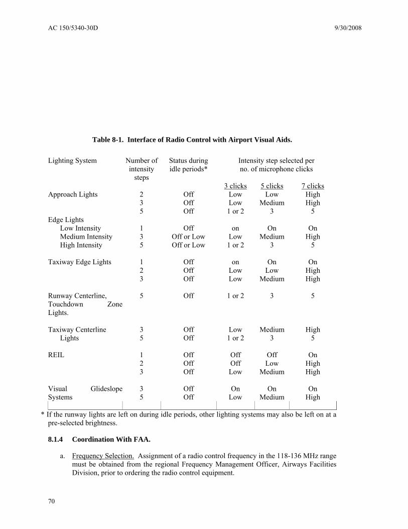
AC 150/5340-30D 9/30/2008
70
Table 8-1. Interface of Radio Control with Airport Visual Aids.
Lighting System
Number of intensity
steps
Status during idle periods*
Intensity step selected per no. of microphone clicks
3 clicks 5 clicks 7 clicks Approach Lights 2 Off Low Low High 3 Off Low Medium High 5 Off 1 or 2 3 5 Edge Lights Low Intensity 1 Off on On On Medium Intensity 3 Off or Low Low Medium High High Intensity 5 Off or Low 1 or 2 3 5 Taxiway Edge Lights 1 Off on On On 2 Off Low Low High 3 Off Low Medium High Runway Centerline, Touchdown ZoneLights.
5 Off 1 or 2 3 5
Taxiway Centerline 3 Off Low Medium High Lights 5 Off 1 or 2 3 5 REIL 1 Off Off Off On 2 Off Off Low High 3 Off Low Medium High Visual GlideslopeSystems
3 5
Off Off
On Low
On Medium
On High
* If the runway lights are left on during idle periods, other lighting systems may also be left on at a
pre-selected brightness.
8.1.4 Coordination With FAA.
a. Frequency Selection. Assignment of a radio control frequency in the 118-136 MHz range must be obtained from the regional Frequency Management Officer, Airways Facilities Division, prior to ordering the radio control equipment.

9/30/2008 AC 150/5340-30D
71
b. Data Reporting. At least 90 days prior to implementing new or retrofitting existing radio control systems, you must report information concerning the use of the system to the FAA for publication in appropriate documents. Information to be reported includes airport name, city or state, sponsor, facilities controlled, runway(s), frequency, and hours of operation. Any special operating features should also be described. This data must be reported to the nearest FAA Flight Service Station or directly to the FAA National Flight Data Center, Air Traffic Operations, Washington DC 20591.

AC 150/5340-30D 9/30/2008
72
Intentionally left blank.

9/30/2008 AC 150/5340-30D
73
CHAPTER 9. STANDBY POWER – NON-FAA.
9.1. BACKGROUND.
FAA policy requires that visual aids associated with facilities in the National Airspace System (NAS) have a definite configuration for electrical power. This chapter contains electrical power details acceptable for non-FAA owned lighting aids, as described in paragraph 9.4.
9.2. DEFINITIONS.
a. "Prime Power Source" denotes the normally available supply of electrical power. This is power furnished by a utility company, the military, or other Government agencies.
b. "Emergency Power Unit(s)" denotes any self-contained device, (e.g., engine generator, battery backup, thermo-electric device, etc.) from which electrical power can be obtained upon failure of the prime power source. See Article 700 of the NEC and local code.
c. "Alternate Prime Power Source" is of the type described in paragraph a above and is a system substantially separate from the first source in that it is arranged so that any single equipment failure, accident, lightning strike, or damage which interrupts power from the first source will not normally interrupt power from the second source.
d. "Quality of Power" denotes the availability of useable electrical power. A power interruption, or a variation of voltage or frequency outside the standards set for the facility will degrade the quality of power for the facility.
e. "Continuous Power Facility" is a facility so designated herein and provided with the quality of power required to assure that the facility’s services continue to meet operational requirements even in the event of an extended widespread loss of commercial power. Continuous power facilities will have power Configuration "A", as specified in paragraph 9.4.a(l).
f. "Continuous Power Airport" is an airport equipped with an emergency power unit(s) which will provide the power required for facilities on the selected runway to sustain operations in visual flight rules (VFR) or IFR conditions in the event of an area-wide or catastrophic-type prime power failure.
g. "Uninterruptible Power" is Configuration "A" power augmented, as necessary, with a device which will assure that power to the load is not interrupted during the 15 second transfer time allowed for Configuration "A".
9.3. FAA POLICY.
Policy requirements are in FAA Order 6030.20, Electrical Power Policy. The power systems for NAS facilities will be of quality sufficient for:
a. Safety of aircraft movement.
b. Efficient air traffic operations.
c. Meeting requirements of national defense.

AC 150/5340-30D 9/30/2008
74
d. Minimizing inconvenience and cost to the aviation community.
9.4. ELECTRICAL POWER CONFIGURATIONS.
a. Basic Configurations. The minimum quality of power needed at a facility varies with the effect that an outage of the facility would have on the provisions of paragraph 9.3. The exact relationship of an individual facility to its environment is, of course, unique; but each type of facility (e.g., HIRL, centerline lights, etc.) has been evaluated for criticalness in the NAS. The evaluation resulted in the development of the configurations listed below:
(1) Configuration “A”. This configuration provides facilities with power from an emergency power unit within 15 seconds after failure of the prime power source, except those CAT II lighting aids (listed in paragraph 9.4.a(2)) requiring a one-second transfer. Details concerning CAT II operation are contained in AC 120-29. The system consists of:
(a) Connection to a prime power source.
(b) Emergency power unit(s).
(c) Automatic transfer capability.
(2) Configuration “B”. This configuration provides facilities with power from an alternate prime power source within 15 seconds after failure of the prime power source except those CAT II lighting aids requiring a one-second transfer. These are CAT II HIRL, centerline lights, and touchdown zone lights. The system consists of:
(a) Connection to a prime power source.
(b) Connection to an alternate prime power source.
(c) Automatic transfer capability.
(3) Configuration “C”. Configuration “C” provides connections of the facility to a single power source. There are no provisions for alternate prime power or engine generator sets. All lighting aids not covered in Configurations “A” and “B” are in Configuration “C”. Even though standby power is not required for Configuration “C”, a higher grade configuration of power is encouraged for airport lighting systems where a second source can be provided at a reasonable cost.
b. Combined Configurations. Systems having two sources of power (Configuration “A” and “B”) must be designed so the second source will be available to the facility within 15 seconds after interruption of the prime power, except that the essential visual aids for CAT II operations require a one-second changeover time. Where the second source of power is an engine generator, the one-second changeover time may be obtained by powering the visual aid facility by the engine generator during CAT II operations using commercial power as the second source (standby). Failure of the engine generator plant is monitored by safety devices which automatically transfer the facility load to commercial power in a nominal one-second changeover time. After prime power is

9/30/2008 AC 150/5340-30D
75
restored and stabilized, the facility must be automatically returned to the prime power supply.
9.5. DESIGN.
Design power systems at all facilities to meet the requirements of the applicable electrical codes. The detailed design requirements for the systems in this AC are flexible to permit the equipment to be installed and operated with minimum changes to the power distribution system at the airport.
a. Configuration “A” Power. (See Figure 92 for configuration.)
(1) KVA Requirements. Prior to the selection of standby power equipment, determine the kilovolt ampere (KVA) input to the regulator. Specification values may be used for this purpose. If qualified personnel are used and the proper equipment is available, the actual input requirements may be determined by the following method:
(a) Set the regulator to supply maximum output current.
(b) Energize the regulator with the lighting load connected.
(c) Measure the volts and amperes at the regulator’s input terminals. Only qualified personnel must make the measurements at the high voltage input of the regulator.
(d) Calculate the input KVA by multiplying the measured volts times the measured amperes and dividing by 1,000. Normally, the measured KVA input to the regulator is less than the calculated KVA input.
(e) If the regulator does not have rated load connected to the output circuit, calculate the KVA input to the regulator with rated load connected. This can be calculated by dividing the rated kilowatts (KW) of the regulator by the regulator’s efficiency and power factor. Typical calculations are shown in Figure 93.
(2) Power and Control.
(a) Design the system to provide an automatic changeover for the prime power to the engine generator equipment within 15 seconds after a power failure occurs. The detailed design requirement for the installation may vary to conform with local conditions, but no variations are permitted in the system’s performance requirements. Additional details are contained in paragraph 9.4 and in Figure 94.
(b) If the engine generator set is not designed to operate continuously under a no-load condition, provide a relay or some other protective device as shown in Figure 94. This relay prevents the engine generator set from operating under a no-load condition in case a power failure occurs when the regulator’s remote control switch is in the “off” position. This is accomplished by bypassing the control switch used to control on/off operation of the regulator. The operation of the engine generators continuously under a no-load condition can affect the equipment’s performance.

AC 150/5340-30D 9/30/2008
76
(c) Space and Ventilation. Provide adequate space and ventilation for the engine generator equipment. The required space, ventilation, and engine exhaust provisions will be controlled by the KVA rating of the engine generator, the design characteristics of the equipment, and the space required to maintain the engine generator set and its auxiliary equipment. Locate the engine generator as close as practical to the CCR it is serving. Typical equipment layout and floor spaces are shown in Figure 95.
b. Configuration “B” Power.
(1) Connection Requirements. Obtain connections for this configuration with one of the methods listed below. See Figure 96 and Figure 97 for typical electrical diagrams and connection details.
(2) Dual Feeders. Separate feeders to the extent that electrical malfunction or physical damage is unlikely to result in outage of both.
c. Configuration “C” Power. This configuration has no provisions for standby power; however, Configuration “A” or “B” is recommended for all visual aids where it can be provided at a reasonable cost.
d. Category II Runway. Provide a one-second power transfer for runway centerline lights, touchdown zone lights, and high intensity runway edge lights on CAT II runways. Methods of obtaining this one-second transfer are contained in paragraph 9.4. At CAT II locations with an engine generator set, use a remote controlled switch on the L-821 control panel to start the standby power when CAT II weather is approaching. Provide a red indicator light on the L-821 panel to indicate “standby on” when the engine generator is running. If the CAT II runway has Configuration “B” power, use automatic transfer switches designed for a one-second or less transfer.
e. Emergency Lighting. Ensure that an adequate number of battery-powered emergency lights are available at all lighted airports for emergency use, per AC 150/5345-50, Specification for Portable Runway Lights.
f. Maintenance Controls. Provide means in the system whereby the maintenance personnel can lock out control switches in order to avoid the equipment being turned on while maintenance personnel are working on the engine generator equipment.
g. Terminal System Integrity. Recognizing that both FAA facilities and those owned by the airport sponsor must be operational to provide basic landing minimums during a power failure, FAA will not upgrade power to existing facilities unless the associated airport-owned facilities conform to the applicable provisions of FAA Order 6030.20.
9.6. EQUIPMENT AND MATERIAL.
a. Engine Generator Set. Unless otherwise specified, select engine generator equipment designed to meet the applicable industry standards and code requirements (diesel preferred; see Article 700 of the NEC and local code). When the engine generator is supplying power to FAA facilities, the engine generator unit must meet the requirements of Specification FAA-E-2204, Diesel Engine Generator Sets, 10kw to 750kw.

9/30/2008 AC 150/5340-30D
77
(1) General Requirement. Provide an engine generator set, for installation in a shelter, that is automatic, quick starting and capable of carrying rated load at all ambient temperatures between 20°F (7°C) and 120°F (49°C). For temperatures below 20°F (7°C), an alternate to supplement shelter heat is a jack water heater (immersion heater). Standby equipment is required to carry rated load within 15 seconds after a power failure. The output voltage of the generator is a value acceptable for connection to the input and control circuit of regulators. Generators required for operation of regulators have a step-up transformer, if required, between the regulators and the generator. Adequate voltage is furnished for the regulator’s control circuits. The output frequency of the generator is 60 hertz, plus or minus commercially acceptable tolerances. Additional details concerning the engine generator set are in paragraph 9.12.
(2) Exhaust System. Provide exhaust silencers (mufflers) and pipes as required for the particular installation. The exhaust pipes, when required, are black steel per ASTM Specification A-53, Standard Specification for Pipe, Steel, Black and Hot-Dipped, Zinc-coated, Welded and Seamless, Type F, Grade A.
(3) Batteries. Provide batteries that have a terminal voltage suitable for starting the engine generator and a minimum watt hour rating per FAA-E-2204. Provide racks for the batteries as required.
(4) Battery Charger. Provide a battery charger with the generator set to assure reliable service from the standby equipment. Unless otherwise specified, battery chargers meet the requirements of FAA-E-2204.
b. Transformer. Provide, if required, a step-up transformer to make the output voltage of the engine generator set compatible with the input voltage to the regulator. Transformers may also be used to step down primary power and permit the use of low voltage automatic transfer switches and to supply control circuits. Select commercial equipment conforming to the applicable industry and electrical standards. Select a transformer rated to supply the required input to the equipment continuously without the transformer overheating.
c. Fuel Storage Tank.
(1) Provide the fuel storage tank with a fuel gauge for the engine generator set. Select a tank with capacity adequate to provide reliable operation for the minimum period of time established by usage of the standby equipment and servicing facilities. If no emergency operating periods are established locally, provide adequate fuel tank capacity for at least 24 hours continuous operation. When selecting a particular size, consider the time required to replenish the fuel supply, the availability of fuel, the accessibility of fuel under adverse weather conditions, fuel required for maintenance test runs (paragraph 9.10.c), and the frequency of maintenance inspections of the fuel tank and supply.
(2) Select a fuel tank that meets the requirements of the NFPA and local codes. Provide fuel lines from the engine generator set to the tank as required by the equipment’s design. Provide an auxiliary tank (day tank) and a transfer pump as required. Storage and auxiliary tanks must be vented per NFPA code.

AC 150/5340-30D 9/30/2008
78
(3) A typical fuel consumption for a diesel engine driven generator set is 2.5 gallons per kilowatt per 24-hour time period at rated load. A typical fuel consumption for a gasoline engine driven generator set is 4.0 gallons per kilowatt per 24-hour time period at rated load.
d. Mounting Pads. If required, provide a mounting pad (foundation) for the engine generator set per the manufacturer’s instructions. If required, provide resilient or shock mounts or an isolated base to control vibration and noise.
e. Conduit and Wiring. Provide all conduit and wiring in the vault or engine generator shelter per the requirement of the NEC and local codes.
f. Radiator Air Duct. Provide, if required, an air duct from the engine radiator to a wall opening. The air intake must be adequate for proper operation and cooling of the equipment.
g. Switch guard.
(1) Provide a switch guard with the engine generator set. This equipment has provisions to switch the regulator’s input from the prime power source to the standby engine generator within the required time interval after power failure is detected. Use a voltage sensing device to detect a power failure. When prime power is restored, the input to the regulator is switched from the standby power source to the prime power source. The automatic transfer switch must meet the performance requirements of FAA-E-2204. This type of automatic switch used with the engine generator is acceptable for Configuration “B” installations.
(2) The switchboard must include safety devices consisting of low oil cutout, high temperature cutout, overcrank cutout, and overspeed cutout. The switchboard must also include indicators such as a voltmeter, ammeter, oil pressure indicator, and water temperature indicator.
(3) Provide a bypass switch per Figure 94 to permit running the engine generator on manual start-stop to facilitate servicing. The bypass switch meets the requirements of FAA-E-2083, Bypass Switch, Engine Generator.
9.7. INSTALLATION.
a. Configuration “A”.
(1) Engine Generator Set and Accessories. Install the engine generator and its accessories per the manufacturer’s instructions. The completed installation must meet all requirements of the NEC and local codes. A typical installation is shown in Figure 95.
(a) Air Intake. Provide access to an adequate quantity of air for the intake of the engine generator. A typical air intake system is shown in Figure 95. A wind baffle fence or other suitable provision may be installed to reduce the back pressure imposed on the engine generator.
(b) Exhaust System.

9/30/2008 AC 150/5340-30D
79
1. Support the exhaust pipe when it is installed through a wall. Where metal plates or metal sleeves are required, use a layer or layers of fireproof vibration-absorbent material conforming to ASTM C-892, Standard Specification for High Temperature Fiber Blanket Thermal Insulation. If the exhaust piping and muffler are not protected, paint them with heat resistant aluminum paint conforming to Federal Specification TT-P-28, Paint, Aluminum, Heat Resisting(1200 Deg. F.).
2. When the exhaust pipe terminates in a vertical direction, install an exhaust pipe rain cap.
(c) Batteries, Battery Charger, and Battery Rack. Install the batteries, battery charger, and battery rack at the location indicated in the plans for the installation. Place the electrolyte in the battery cells after the batteries are in their final position.
(2) Fuel Storage Tank and Lines. Install the fuel storage tank and lines and auxiliary tank (day tank) per the equipment manufacturer’s instructions, NFPA code, and local code requirements.
(3) Transformer. If a step transformer is required, install the step-up transformer at the location indicated in the plans. Make connections to the transformer per the equipment manufacturer’s instructions.
(4) Mounting Pads. Specify mounting pads to support the equipment being installed.
(5) Transfer Switch. Install the transfer switch at the location indicated in the plans. A typical location of this equipment is shown in Figure 95.
(6) Conduit and Wiring. Install conduit and wiring per the NEC and local code requirements.
b. Configuration “B”. The Configuration “B” power for non-FAA airport lighting systems is normally installed by the utility company(s); however, obtain assurance that the installation will meet the configuration and design requirements of paragraphs 9.4 and 9.5, respectively.
c. Configuration “C”. There are no provisions for the installation of standby power with this configuration. However, Configuration “A” or “B” is encouraged for all visual aids where it can be provided at a reasonable cost. See Figure 98 for a typical electrical layout.
9.8. INSPECTION.
a. System. Check the electrical configuration of the system to determine if the design meets the requirements of this chapter.
b. Engine Generator Set.
(1) Inspect the engine generator set and its accessories to assure that the equipment is installed per the equipment manufacturer’s instructions.

AC 150/5340-30D 9/30/2008
80
(2) Check the mounting of the engine and generator to determine if the equipment is securely mounted.
(3) Check all pipes, conduits, and accessories to determine if each item is securely fastened.
(4) Check all wiring to determine if it is correct and that all connections are secure.
c. Fuel Storage Tank and Line. Inspect the fuel storage tank, auxiliary tank (day tank), and lines to determine if the equipment is properly installed and that there are no fuel leaks.
d. Batteries. Check all connections to determine if they are secure and that the electrolyte in the battery cells is at the proper level.
e. Output Voltage. Check the output from the engine generator set to determine if the voltage is adequate for the regulator’s input power and control circuits. Make this check prior to connecting the regulator to the engine generator set.
9.9. TESTS.
a. Engine Generator Set and Switchboard:
(1) Conduct tests recommended in the manufacturer’s instructions.
(2) Test the installation by operating the system continuously for at least one hour. In addition, simulate at least 10 power failures and check the starting time of the engine generator equipment. Check the operation of all safety and indicating devices specified in paragraph 9.6.
(3) Test the operation of the bypass switch.
(4) Test the operation of components used to obtain an automatic transfer of power from the prime source to the standby equipment.
b. Batteries. Test the batteries to determine if the specific gravity is within the range recommended by the manufacturer.
9.10. MAINTENANCE.
a. General. The equipment manufacturers issue specific instructions for their engine generator equipment. These instructions contain information obtained through experience and they are provided to assure reliable and efficient service from the equipment. In view of this, the instructions must be read, understood, and followed. The engine generator set and its accessories must be maintained by qualified personnel.
b. Engine Generator Set. Perform preventive maintenance on the engine generator set per equipment manufacturer’s instructions.
c. Operational Check. Make a weekly operational check of the engine generator and associated equipment operating the emergency system for one hour minimum, while it is supplying power to the lighting systems, preferably at maximum brightness. Since the

9/30/2008 AC 150/5340-30D
81
engine generator feeds the lighting system rather than a load bank, coordinate all operational checks with ATCT personnel.
d. Vault or Shelter. Keep the enclosure housing, the engine generator set, and its accessories clean and uncluttered to prevent dirt from accumulating in control compartments and to allow equipment to be accessible at all times. Mount warning signs in conspicuous locations.
e. Tank and Fuel Line. Check fuel tank covers and fuel line after each refueling to determine that these components are secure and that there are no fuel leaks.
f. Spare Parts. Stock adequate spare parts for maintenance purposes. Use the manufacturer’s instructions as a guide concerning maintenance spares.
g. Log. Keep a log of engine generator operating hours (or provide an elapsed time meter) and a record of maintenance work performed on the equipment.
h. Fuel Supply. Establish a regular schedule for checking the fuel supply. The regularity must be established on the basis of the type facility, location of the engine generator sets, and location of the fuel supply. For example, thought must be given those locations near where CAT II minimums exist for several days at a time.
9.11. REDUCING ELECTRICAL POWER INTERRUPTIONS.
The sections of FAA Order 6950.11, Reduced Electrical Power Interruptions at FAA Facilities, pertaining to non-FAA airport lighting systems, are applicable to this circular.
9.12. ENGINE GENERATOR EQUIPMENT PERFORMANCE REQUIREMENTS.
a. Referenced Specification. FAA-E-2204 may be used as a guide in selecting standby power equipment. Because the requirements for airport lighting are not as rigid as those for supplying power to radar and communication facilities operated and maintained by the FAA, the requirements in FAA-E-2204 may be modified as indicated below.
b. Modification to FAA-E-2204C, pages 3-32:
Chapter 3. Requirements.
Paragraph 3.1 Description. Modify to permit transfer switches to be mounted on the wall instead of on the engine generator.
Paragraph 3.2.2 Interchangeability. Delete. Not applicable.
Paragraph 3.2.4 Painting. Modify to eliminate any certain color, to permit use of manufacturers’ standard colors.
Paragraph 3.2.7 Spare Parts. Delete.
Paragraph 3.2.8 Nameplate and Serial Numbers. Delete requirements for FAA standard nameplate. All other nameplates should be required.

AC 150/5340-30D 9/30/2008
82
Paragraph 3.2.10 Instruction Book. Delete all reference to Specification FAA-D-2494.
Paragraph 3.3.2 Engine Description. In the second paragraph, this specification states that the “Maximum brake horsepower and speed of the engine must be a specified in the Classification Table, Figure 1.” This Classification Table should be modified to delete the developed horsepower at synchronous speed and permit higher speed on the larger plants.
Paragraph 3.3.10 Governor and Frequency Regulation. Close tolerances on frequency requirements may be relaxed. Standard commercial tolerance is acceptable.
Paragraph 3.4.1 Generator. Eliminate the requirement for parallel operation.
Paragraph 3.4.11 Load Test Jacks. Load test jacks are not required and should be eliminated.
Paragraph 3.4.12 Automatic Power Transfer Equipment. Modify this item to permit the transfer switch and equipment to be mounted on the wall adjacent to the engine generator.
Paragraph 3.4.12.2 Automatic Transfer Switch. Modify to permit wall mounting.
Chapter 4. Inspection and Tests.
Chapter 5. Preparation for Delivery. All reference to the tests and inspections shown in 4.1 to 4.2.5 pages 32-42 inclusive, should be deleted. However, the manufacturer must certify that the plant furnished will meet the above tests.
Page 44, Classification Table. Delete developed HP at synchronous speed. The manufacturer must supply an engine of sufficient horsepower rating to develop the full KVA rating of the plant.
Maximum Speed RPM. Increase all 1200 RPM to 1800 RPM.

9/30/2008 AC 150/5340-30D
83
CHAPTER 10. PAVEMENT TYPES.
10.1. GENERAL.
There are four types of pavements used in the construction and installation of airfield lighting systems. These can be capable of rollover (considered full strength), or on a shoulder area not capable of rollover.
10.2. NEW PAVEMENT – RIGID (CONCRETE).
One of two conditions will be encountered during installation. The edge of an existing pavement will be available as a reference for the new bases, or if an existing edge is not available, the bases should be set “in space.” The availability of an existing pavement edge simplifies the task of locating the light base. In both cases, a setting jig or fixture is required to hold the base in position while the concrete anchor is placed. Azimuth and the elevation of the base with respect to the pavement surface are two parameters that should be met. It is imperative that the elevation of the mounting flange be at least ¾ inch (19 mm) below the finished surface of the pavement. If the base is positioned less than ¾ inch (19 mm) below the pavement surface, the light fixture will protrude above the pavement surface and may adversely affect its performance and present a hazard to vehicles operating on the pavement, such as snowplows. If more than ¾ inch (19 mm) is left, spacer rings can be used to bring the light fixture to the correct elevation. In order to preserve the base integrity and proper bolt torque, a maximum of three spacer rings may be stacked together. A paving tolerance of ½ inch (13 mm) should be anticipated when setting the elevation of the base, so the light fixture can be set at +0 to –1/16 inch (+0 to –1.5 mm) below the low side of the pavement surface.
a. Excavate conduit runs in the base or sub-base supporting the rigid pavement. Place conduit and counterpoise at this time. Counterpoise must be installed above the conduit.
b. At each light location, excavate the pavement base or subbase to accommodate the L-868 light base, the steel reinforcing cage, and concrete for the anchor. The concrete anchor should provide a 6-inch (152 mm) thickness below the light base and a 12-inch (305 mm) thickness of concrete around the perimeter of the light base. The volume of the concrete anchor must not be less than 1/3 cubic yard. The reinforcing steel cage is made from #4 steel bars, ASTM grade A-184 or A-704. The vertical bars of the cage are spaced 12 inches (305 mm) apart and arranged in a circular pattern 6-inches (152 mm) greater in diameter than the light base. The vertical bars extend from 3 inches (78 mm) below the theoretical pavement surface to 6 inches (152 mm) into the concrete base, with 4-inch (102-mm) 90-degree hooks at each end. The horizontal bars are spaced at 12 inches (305 mm), beginning at the 90-degree hook, and encircle the vertical bars.
c. After the excavation is complete, install the light base and reinforcing steel cage and hold them in place with the setting jig. The top of the light base should be covered with a steel mudplate and a ⅝ inch (16-mm) thick plywood cover to protect the top of the light base immediately prior to paving. The setting jig will establish the elevation and azimuth of the base and maintain this position until the concrete anchor is placed. We recommend connecting each base to the conduit system per Figure 35. Flexible conduit may be used will allow adjustments in light base elevation and alignment before the concrete anchor is placed. If the conduit/light base misalignment is not more than approximately 15 degrees, a flexible grommet may be used on the light base vice a threaded hub. When

AC 150/5340-30D 9/30/2008
84
using a flexible grommet, steel conduit should enter the light base about ¾ inch and PVC should enter about ¼ inch.
d. Connect conduits to the bases and pull the cabling into the bases. Bond the counterpoise to the light base and rebar cage. Exothermic welds are the preferred connection method of connection. If exothermic welds are not possible, ensure that all connector materials are UL listed for direct earth burial and/or installation in concrete. See Chapter 12, Section 12.5 for additional details about counterpoise bonding.
e. Set the final position of the bases with the setting jig. The top of the light base should be 1½ inch (35 mm) below the finished surface of the pavement. This can be accomplished by using a ¾ inch (19 mm) spacer between the setting jig and the plywood cover. See The Design, Installation, and Maintenance of In-Pavement Airport Lighting, Arthur S. Schai, for additional information.
NOTE: Coordination is required between the pavement and lighting installation activities to avoid an incorrectly installed light fixture base or excessive variations in pavement thickness.
f. Place a sufficient amount of concrete (1/3 cubic yard minimum) to completely fill the excavation for the anchor up to the level of the pavement base or sub-base. The light base concrete anchor must not encroach upon the structural pavement thickness. The concrete should conform to the requirement cited in paragraph 12.7. Take care while placing the concrete anchor that neither the jig nor the light base alignment is disturbed. The jig must remain in place until the concrete has set, usually 24 hours. Backfill the conduit runs with concrete at this time.
g. Prior to paving, remove the plywood cover and fit the light base with a steel mudplate. After the paving train has cleared the light base, remove the concrete from the top of the base and finish the edge of the opening around the base to a smooth radius. The surface of the pavement around the light base must be level with the surrounding pavement; dished or mounded areas are not acceptable. The grooved spacer ring or flat spacer ring may also be provided with an integral protective dam that will allow the installation of AC 150/5370-10, P-605 or P-606, sealant in the annular space around the fixture. After the concrete has set, remove the mudplate and determine the actual thickness of concrete above the light base. It may be necessary to install a grooved space ring, or grooved spacer ring and flat spacer ring, or set this level of adjustable cans to bring the light fixture to the correct elevation. In order to preserve the base integrity and proper bolt torque, a maximum of three spacer rings may be stacked together. Install silicone sealant RTV-118, or equivalent, between the mating surfaces.
h. The top of the fixture edge (highest edge if fixture is not exactly level and/or installed on a crowned pavement) must be between +0 inch (0 mm) and −1/16 inch (2 mm) from the pavement surface. You must take remedial action if the fixture is too high. This could result in field modification of the base that could affect equipment certification. Prior to any remedial action, you must consult with the base manufacturer. See Figure 34 for application of tolerance on crowned pavement sections.
i. The installation of the primary cable, transformers, and connectors can be completed. Install an “O” ring gasket (normally supplied with the light fixture). Then, install the

9/30/2008 AC 150/5340-30D
85
hold-down bolts, with 2-piece anti-vibration lock washers, and tighten them to the manufacturer’s recommended torque.
NOTE: If the paving technique utilizes more than one lift to achieve the required thickness, the above procedure is altered as follows: a sectional light base is required and, after the bottom section has been installed as described above, the first paving lift should be placed. Expose and clean the flange and install the next base section with a silicone sealant, equal to RTV-118, between the sections. Tighten in place. The paving operation and the fixture installation are as described above.
10.3. NEW PAVEMENT – FLEXIBLE (BITUMINOUS).
a. A sectional base is required for flexible pavements. The bottom section of the light base, concrete anchor, and the conduit system are installed in the pavement base using procedures similar to those for rigid pavements. Certified adjustable bases can also be installed. See paragraphs 11.1.a and 11.4. No steel reinforcing cage is used in this application. See The Design, Installation, and Maintenance of In-Pavement Airport Lighting, Arthur S. Schai, for additional information.
NOTE: Because of the loads placed on the cover plate during paving, a plywood cover with a minimum thickness of ⅝ inch (16 mm) should be used. If the top section will not be installed right away, a galvanized steel mudplate ⅛ inch (3 mm) thick should be used.
b. The first two steps of this procedure are identical to those for the installation of fixed body length bases in rigid pavement, except that a steel reinforcing cage is not required.
c. After the excavation is complete, install the bottom section of the light base and hold it in place with the setting jig. Install a ⅝ inch (16-mm) thick plywood cover to the top of the bottom section to protect the top prior to and during paving. The setting jig will establish the elevation and azimuth and maintain this position until the concrete anchor is placed. A recommended practice is to connect each bottom section to the conduit system with a length of liquid tight flexible conduit, as shown in Figure 35. Flexible conduit will allow adjustments in light base elevation and alignment before the concrete anchor is placed.
d. Connect conduits to the base and pull the cabling into the bottom section of the base. Bond the counterpoise to the light base.
e. Set the final position of the bottom section of the base with the setting jig. Install a ⅝ inch (16-mm) thick plywood cover to the top of the bottom section to protect the top prior to and during paving. This can be accomplished by using a ¾ inch (19-mm) flat spacer ring between the setting jig and the plywood cover.
f. Place a sufficient amount of concrete to completely fill the excavation for the anchor up to the level of the pavement layer to be placed. The concrete should conform to the requirement cited in paragraph 12.7. Take care while placing the concrete anchor so neither the jig nor the light base alignment is disturbed. The jig must remain in place until the concrete has set, usually 24 hours.
g. After the paving train has cleared the light base, remove the paving material and plywood cover from the top of the bottom section of the base, exposing the flange. Clean the flange and apply a silicone sealant equal to RTV-118.

AC 150/5340-30D 9/30/2008
86
h. Attach the middle section of the sectional base to the bottom section, per manufacturer recommendations. The thickness of the middle section should be such that the elevation of the top of the middle section is 1⅜ inch (35 mm) below the finished surface of the next pavement layer to be placed. Install a ⅝ inch (16-mm) thick plywood cover to the top of the middle section to protect the top prior to and during paving.
i. Once again, after the next pavement layer has been placed, remove the paving material and plywood cover from the top of the middle section of the base, exposing the flange. Clean the flange and apply a silicone sealant equal to RTV-118.
j. Bolt a top section of a base onto the middle section, per manufacturer recommendations. The thickness of the top section should be such that the elevation of the top of the section is 1⅜ inch (35 mm) below the finished surface of the flexible pavement.
k. After paving is completed, bore a 2-inch (50 mm) hole through the pavement surface layer to accurately locate the center punch mark of the cover plate. Core a hole 1 inch (25 mm) larger in diameter than the base centered over the base. Install the grooved spacer ring and any necessary flat spacer rings to position the light fixture at the FAA specified elevation for the lighting system being installed. In order to preserve the base integrity and proper bolt torque, a maximum of three spacer rings may be stacked together.
l. The top of the fixture edge (highest edge if fixture is not exactly level and/or installed on a crowned pavement) must be between +0 inch (0 mm) and −1/16 inch (2 mm) from the pavement surface. See Figure 34 for application of tolerance on crowned pavement sections.
m. Fill the space between the walls of the cored hole and the outer walls of the top section with liquid AC 150/5370-10, P-606 sealant that is compatible with asphalt. After the AC 150/5370-10, P-606 sealant has cured, fill the remaining space with AC 150/5370-10, P-605 Type III sealant (which is compatible with asphalt) up to the top of the protective dam, if installed, or up to the top of the grooved spacer ring.
n. Complete the installation of the primary cable, transformers, and connectors. Install an “O” ring gasket. Then, install the hold-down bolts, with lock washers, and tighten them to the manufacturer’s recommended torque.
10.4. OVERLAY – RIGID.
a. With Existing Lights ⎯ This procedure assumes that the existing pavement being overlaid has load bearing lights that are in satisfactory condition:
(1) Remove all existing light fixtures and related components. Existing components in good condition may be reused, if appropriate. Protect the ends of existing cables with tape.
(2) Determine the length of the light base extension required to position the light fixture at the specified elevation for each light location. Fit each extension with a mudplate and plywood cover to protect the flange during the paving operation. After the paving train has cleared the light base, remove excess concrete from the top of the extension and finish the edge of the opening around the base to a smooth radius. The
9/30/2008 AC 150/5340-30D
87
surface of the pavement around the light base must be level with the surrounding pavement; dished or mounted areas are not acceptable. See Figure 34 for the tolerances on light fixture elevations on crowned pavement. The installation should be made with utmost care to avoid costly remedial action. The thickness of the plywood and mud plate must be such that the mud plate is level with the surface of the pavement to be overlaid to allow clearance for the paving operation.
(3) After the pavement has hardened, check the elevation of the top flange in relation to the finished surface. It may be necessary to install a grooved spacer ring, or grooved spacer ring and flat spacer ring, to bring the light fixture to the correct elevation. For adjustable cans, see paragraphs 11.1.a and 11.4.
(4) Next, install primary cable, transformers, and connectors. Install an "O" ring gasket. Then, install the hold-down bolts and tighten them to the manufacturer’s recommended torque.
(5) If the paving technique uses more than one lift to achieve the required thickness, alter the above procedure, as follows:
(a) A sectional light base is required.
(b) After the bottom section has been installed as described above, place the first paving lift.
(c) When the flange is exposed, clean it and install the next base section with a silicone sealant equal to RTV-118 between the sections.
(d) Tighten the sections in place.
(e) Install lights.
(f) See paragraph 10.4a(4).
(6) Without Existing Lights ⎯ The installation of a light base and conduit system in a pavement to be overlaid with concrete is similar to that of a new rigid pavement installation, except that the bottom section of the light base and the conduit are set in openings made in the existing pavement. The required concrete anchor and steel reinforcing cage will be similar to that described in paragraph 10.2.b. The use of a short length of liquid-tight flexible conduit is usually necessary to allow proper alignment. The installation of the conduit system will require sawing and trenching the existing pavement or the use of directional boring beneath the existing pavement. Directional boring techniques have been successfully used for lights located nearer the edge of wide pavements.
10.5. OVERLAY - FLEXIBLE.
a. With Existing Lights ⎯ This procedure assumes that the pavement being overlaid has existing load bearing lights that are in satisfactory condition. See Figure 99.

AC 150/5340-30D 9/30/2008
88
(1) Remove all existing light fixtures and related components. Existing components in good condition may be reused, if appropriate. Protect the ends of existing cables with tape.
(2) Install a plywood cover with a mud plate (see AC 150/5345-42) on the existing base. The thickness of the plywood and mud plate must be such that the mud plate is level with the surface of the pavement to be overlaid to allow clearance for the paving operation.
(3) After the pavement overlay has been placed, locate the mud plate by using a metal detector, magnet, or precise surveying. Core out a 1 to 2 inch (25 to 50 mm) diameter hole in the overlay pavement down to the mud plate. Using the pattern of the raised concentric circles on the mud plate, determine the center of the light base.
(4) Mark the pavement for coring using the center of the light base as the center of the core. The core diameter should be equal to the light base diameter, plus 1 inch (25 mm). Core drill through the new overlay pavement sufficiently deep to remove the overlay pavement, the steel protection plate, and the plywood cover. For adjustable cans, see paragraphs 11.1.a and 11.4.
(5) Order light base extensions and grooved spacer rings to the total length required to place the light fixture at the proper elevation.
(6) Once the extensions and grooved spacer rings are received, bolt them in place on the existing light bases. Install the "O" ring in the grooved spacer rings in the light fixture. Install the light fixture and apply nickel-based anti-seize compound to all bolts and torque them to the manufacturer recommendations. Fill the void surrounding the extension with sealant until it is level with the top of the protective dam. Take caution to prevent any sealant from flowing over the top of the protective dam.
b. Without Existing Lights ⎯ The installation of a light base and conduit system in a pavement without lights to be overlaid is similar to that of a new flexible pavement installation, except that the bottom section of the light base and the conduit are set in openings made in the existing pavement. The required concrete anchor and encasement of the conduit will be similar to that described in paragraph 10.5.a. The use of a short length of liquid-tight flexible conduit will allow proper alignment.

9/30/2008 AC 150/5340-30D
89
CHAPTER 11. FIXTURE MOUNTING BASES
11.1. GENERAL.
This section recommends installation methods and techniques. Other methods and techniques, and variations of those outlined here, may be used provided they are approved by the appropriate district FAA Airports Office. Correct placement of the lights is of prime importance; to achieve this, careful attention to detail is required. Survey instruments may be used to accurately position all fixtures for their precise location, elevation, and azimuth. The tolerances required in other FAA Advisory Circulars, this specification, and the plans must not be exceeded. The light beam must be aligned as described in the lighting system manual with a tolerance of ± 1 degree. The lighting fixture must be level, and the top of the fixture edge must be between +0 inch and -1/16 inch from the pavement top; see Figure 34 for application of tolerance on crowned pavement sections:
a. Fixture Mounting Bases L-868. The L-868 bases are load-bearing bases and are certified to AC/150/5345-42. There are adjustable height bases that have been certified. Installation methods for these bases must adhere to manufacturer’s instructions.
11.2. L-868 MOUNTING BASES.
a. New Rigid Pavements. This system requires careful attention to detail during installation. One of two conditions will be encountered during installation: the edge of existing pavement will be available as a reference for setting the new bases; or no existing edge is available and the bases must be set “in space.” The availability of an existing pavement edge simplifies the task of positioning the light base to the theoretical pavement grade. However, a setting jig is required to hold the base in position while the concrete anchor is placed. See Figure 35, Figure 100 and Figure 101. Elevation of the base with respect to the runway surface and azimuth with respect to the centerline are two parameters that must be met. It is absolutely necessary that the elevation of the light base top flange be at least the thickness of the light fitting plus the thickness of typical paving tolerances (± ½ inch (13 mm)) below the pavement finished surface. If less than that remains after paving, the lighting fixture will be unacceptably high. If more than 3/4 inch (19 mm) is left, flat spacer rings can be used to bring the lighting fixtures up to the correct elevation. In order to preserve the base integrity and proper bolt torque, a maximum of three spacer rings may be stacked together.
(1) At each light location, make an excavation in the runway base which is large enough to accommodate the light base, the reinforcing steel cage, and concrete for the anchor. [Typical excavation is 6 inches (152 mm) around the base and 6 inches (152 mm) beneath the base.] After the excavation is completed, the light base and reinforcing steel cage are installed and held in place with the jig. The jig will establish the elevation and azimuth of the base and maintain this position until the concrete anchor is placed. If bases have threaded conduit openings, take care so the conduit does not move the base. Using 2 feet (0.6 m) of flexible conduit on one entry to the base can resolve this concern. If bases are provided with openings, neoprene grommet slip connections offer more flexibility and can be installed directly into the base. Flexible conduit or grommet conduit openings will allow adjustments in light base alignment before the concrete anchor is placed.

AC 150/5340-30D 9/30/2008
90
(2) Take care while placing the concrete anchor that neither the jig nor the light base alignment is disturbed. The jig must remain in place until the concrete has set. During paving operations the light base may be fitted with a steel cover plate (mud plate). After the paving train has cleared the light base, remove excess concrete from the top of the base, and the edge of the opening around the base should be finished to a smooth radius. An alternative is to allow the pavement to cure and using a core bit, core the opening directly over the light base.
(3) The surface of the pavement around the light base must be level with the surrounding pavement; dished and mound areas are not acceptable. In addition, check the elevation of the top flange in relation to the finished surface. It may be necessary to install a grooved spacer ring, and/or flat spacer ring, to bring the light fixture to correct elevation. Next, install primary cable, transformers, and connectors. Connect lighting fixture to secondary cable. Install “O” ring gasket if using grooved spacer ring and torque hold-down bolts to manufacturer’s recommendations.
(4) If the paving technique utilizes more than one “pass” of the paving machine, the above procedure is altered as follows: a sectional light base is required; after the bottom section has been installed as described above, the first pass is completed. The flange is then cleaned and the next section is installed with a silicone sealant equal to RTV-118 between flanges, and torqued in place. The paving proceeds, and the fixtures are installed as above. A well-designed system will be equipped with drains, as required at the low spots.
b. New Flexible Pavement. A sectional base is required for flexible pavement. Because flexible pavement finished elevation can settle, it is necessary for the installation design to take this fact into account. The light fixture must be able to be lowered without requiring the base to be removed.
(1) The bottom section of the light base (including concrete anchor) and the conduit system are installed in the pavement base as described in the preceding paragraph. It is then paved over. The light base with a 5/8 inch (16 mm) thick plywood cover and mudplate (target plate), concrete anchor, and conduit backfill must not be higher than the base surface. After the paving is completed, a 2 to 4 inch (50-100 mm) hole is bored to accurately locate the center punch mark of the bottom section of the mudplate. If the bottom section is to be buried for longer than 90 days before discovering, it is suggested a ¾ inch (19 mm) thick galvanized mudplate be utilized in lieu of plywood.
(2) Obtain a combination of a base top section and a grooved spacer ring or flat spacer ring (for future adjustability) that will equal ¾ (19 mm) less than the dimension measured. When the top section is received, a core opening 1 inch larger than the diameter of the light base should be drilled and the top section, grooved spacer ring and light fixture installed.
(3) The space between the walls of the hole up to the top of the top section should be filled with AC 150/5370-10, P-606 sealant compatible with asphalt. The remaining space should be filled with AC 150/5370-10, P-605 sealant to the top of the protective pavement dam on the grooved spacer ring or flat spacer ring. See Figure 36.

9/30/2008 AC 150/5340-30D
91
c. Flexible Overlay. The installation of the light base and conduit system in a pavement to be overlaid is similar to that of a new flexible pavement except the bottom section of the light base and the conduit are set in openings made in the existing pavement. The required concrete anchor and encasement of the conduit will be similar to that described in paragraph 11.2.b.
d. Rigid Overlay. The installation of the lighting base and conduit system requires a combination of techniques outlined in preceding paragraph 11.2.a, and paragraph 11.2.c. The base and conduit are installed as in paragraph 11.2.c; concrete is placed as in paragraph 11.2.a.
11.3. DIRECT-MOUNTED (INSET) FIXTURES.
While the installation of direct mounted fixtures is becoming less common, there are instances when they are still applicable, e.g., overlays. We do not recommend the use of direct mounted fixtures for flexible pavements in very cold climates. There are two different types of direct mounting: base-mounted and direct mounted. Base mounting requires shallow inset bases that provide a mounting flange and a cavity for the cabling. Direct mounted fixtures are constructed so that the fixture itself can be mounted in the pavement. Installation details are similar for both types. In both instances, the pavement directly supports the base or fixture. The pavement is cored to a depth necessary to accept the shallow base, and the base is secured to the bottom of the cored hole with mechanical fasteners and adhesives. For additional details, see Figure 38, Figure 39, Figure 40, Figure 41, Figure 42, Figure 102, Figure 103, Figure 104, Figure 105 and Figure 106.
a. Rigid Pavements. The installation procedures for direct mounted fixtures in rigid pavements are the same, whether the pavement is new, overlay, or existing. Holes or recesses in the pavement must be cored to accommodate the shallow bases or fixtures and wireways must be sawed to accommodate electrical wiring. If wireways have been wet-sawn, flush these wireways with a high velocity stream of water immediately after sawing. Prior to installation of the sealer, the wireways must be clean and dry.
(1) Pavement Coring and Sawing ⎯ Provide approximately ¼ inch (6 mm) clearance for sealant material between the bottom and sides of the shallow base or fixture and the recess. Provide extra depth where sawed wireways cross pavement joints. See Figure 38 for details.
(a) Prior to placing the shallow inset base or fixture into the cored hole, clean all external surfaces to ensure adequate bond between the base, sealer, and pavement. Sandblast the area as necessary. When placing the light fixtures, avoid handling the fixtures by the electrical leads.
(b) Orient the fixture and arrange the leads properly with respect to their splicing position in the wireways. Use temporary dams, if required, to block the wireway entrance into the drilled hole. These dams will retain the sealer during the setting of the inset base receptacle. The positioning tolerances for the base or fixture must be per FAA specifications for the type of lighting system being installed. Rugged, well-designed jigs are required to ensure proper azimuth, elevation, and level.

AC 150/5340-30D 9/30/2008
92
(c) Cover the bottom of the inset base or fixture with AC 150/5370-10, P-606 or an approved equal paste type adhesive material. Also, place paste in the cored hole. Place the base or fixture in the cored hole to force adhesive up the sides of the base at least ⅛ inch (3 mm). Take care to work out any entrapped air. Use a liquid sealer, AC 150/5370-10, P-605 or approved equivalent, to fill the space between the base and the sides of the cored hole. Liquid sealer must be applied only between the inset base receptacle and the sides of the cored hole and must not be applied between the sides of the cored hole and the top assembly (see Figure 103).
(d) Typical transformer housing and conduit installation details for direct mounted lighting systems are shown in Figure 37, Figure 40 and Figure 102.
(2) Wireways ⎯ Prior to installing the wires in the pavement, chamfer or round to a 2 inch (50 mm) radius the vertical edges of the wireways at intersections and corners (see Figure 103). Sandblast and clean wireways to ensure a proper bond between the pavement and the sealer.
(3) Wires ⎯ Place the #10 AWG THWN wires in the wireways from the transformers near the taxiway edge to the light fixture leads. Use an adequate number of wedges, clips, or similar devices to hold the wires in place at least ½ inch (13 mm) below the pavement surface. The spacing between wedges, clips, etc., must not exceed 3 feet (0.9 m). Wood wedges and plugs are not acceptable. Install the tops of the wedges below the pavement surface. Splice the light fixture leads to the #10 AWG wires. Use pre-insulated connectors. Make the crimped splice with a tool that requires a complete crimp before releasing. Stagger the location of the splices. Permit no splices in the single conductor wires at each fixture. Where splices are unavoidable, they will be made only in approved L-868 bases (see Figure 42). If the installation is made in stages, tape or seal the ends of exposed wires to prevent the entrance of moisture. Seal the wires in the wireways with AC 150/5370-10, P-606 material. Adhesive must be applied on a dry, clean surface, free of grease, dust, and other loose particles. The method of mixing and application must be per AC 150/5370-10 and in strict accordance with manufacturer recommendations. Installation methods, such as surface preparation, mixing ratios, and pot life, are as important to satisfactory performance as the properties of the material. You may wish to require a manufacturer’s representative to be present during the initial installation of the material to ensure the installation procedures are per manufacturer directions and the following steps:
(a) Pour sealant in the wireway until the surface of the wire is covered.
(b) If recommended by the manufacturer, pour clean sand into the liquid sealant until a slight amount of sand shows on the surface. Use clean sand that can pass through a number 40 (425 μm) sieve.
(c) Fill the remainder of the wireway with a liquid sealant to between ⅛ inch (3 mm) and ¼ inch (6 mm) below the pavement surface.
b. Flexible Pavements ⎯ The installation procedures for direct mounted fixtures in flexible pavements are the same whether the pavement is new, overlay, or existing. Install direct

9/30/2008 AC 150/5340-30D
93
mounted light fixtures and wires in flexible pavements in a manner similar to the installation procedures for rigid pavements, with the following precautions:
(1) Clean the holes and wireways immediately before installation so that the clean, dry aggregate of the pavement is exposed.
(2) Use a sealant that conforms to AC 150/5370-10, P-606 and is compatible with asphalt per ASTM D-3407, Standard Test Method for Joint Sealants, Hot Poured, for Concrete and Asphalt Pavements, to seal wires in wireways.
(3) Mix the AC 150/5370-10, P-606 sealant (for use on fixtures) so that it sets up within 15 minutes.
(4) Install the junction boxes on runways where overlays are anticipated. When additional pavement is required, remove the inset light and fit the base with a cover. Apply paving over the light base and junction box. When the paving is complete, expose the junction box and light base by coring. Remove the covers.
11.4. FIELD ADJUSTABLE L-868 MOUNTING BASES.
a. General.
(1) L-868 bases may be utilized that have an integral top section and an extension that is capable of being field adjusted to the height of the surrounding pavement. These bases are suitable for use in many of the applications that would normally require the addition of bases’ extensions or flat spacer rings in order to raise the base flange ring to the surrounding pavement elevation (see paragraph 11.2.b(2) as an example). These field adjustable bases and extensions vary in how they must be installed, but they still must be able to meet the same elevation and azimuth alignment requirement (paragraph 11.1) along with a future adjustability capability, as required, of conventional bases and extensions.
(2) The inspection authority must, at the time of installation, ensure that the bases are installed per the manufacturer’s instructions and that the locking devices are correctly installed. Failure to do so may compromise the base’s ability to withstand the loading and torque requirements specified for a load bearing base.
11.5. INSTALLATION.
The systems must be installed per the NEC as applicable and/or local code requirements:
a. L-867 Light Base and Transformer Housing for Elevated Light Fixtures. When using non-adjustable cans, the light base must be as shown in Figure 23. If the soil is unsuitable, then an adequate depth of soil must be removed and replaced with compacted acceptable material. The cable entrance hubs must be oriented in the proper direction. Level the light base so that the mounting flange surface is approximately 1 inch above the finished grade. With the base properly oriented and held at the proper elevation, place approximately 4 inches (10 cm) of concrete backfill around the outside of the base. The top of the concrete must be sloped away from the flange portion of the base so the sloped outer edges of the concrete are at surface grade. If concrete backfill is omitted, select earth backfill must be compacted to maintain proper orientation and elevation of the base.

AC 150/5340-30D 9/30/2008
94
In closed duct systems installed in soil conditions of good drainage, use light bases having a drain hole to prevent water accumulation.
b. Light Base and Transformer Housing for In-pavement Light Fixtures. The base is supported in the leave-out or excavated area in a position as shown in Figure 35 and Figure 36. Orient the base so that the cable entrance hubs on the base are properly aligned and so that the in-pavement light fixture will be properly aligned, when installed, prior to placing the concrete backfill. When installed in bituminous pavement, leave the concrete backfill 3-4 inches (8-10 cm) low to allow completing the backfill with bituminous material after the concrete has cured.
c. Stake (Angle Iron) Mounting. Install the stake in a 6 inch (15 cm) diameter hole at a depth of 30 inches (76 cm) as shown in Figure 23. Do not install stake by driving. Make electrical connections and backfill around the stake with thoroughly compacted earth passing a 1 inch (2.54 cm) sieve. Where required due to unstable soil conditions, backfill with concrete. Install the top of the stake even with, or not more than 1/2 inch (1.3 cm), above the finished grade and maintain within 1 degree of the vertical. In areas where frost may cause heaving, anchor the stake with concrete and use a permeable backfill material such as sand around the buried electrical components and then cover the top surface with an impervious material to reduce moisture penetration.
d. Light Fixtures - General. The light fixtures are supplied unassembled and consist of an optical system, lamp, connecting leads, and a mounting assembly. The installer must assemble, connect to mounting, level, and adjust the light fixture per the manufacturer’s instructions. Take care that the lamp specified by the manufacturer for the particular use of the light fixture is installed. The light fixtures must be leveled and aligned, where appropriate, within 1 degree. The standard height of the top of the elevated light fixture is 14 inches (35 cm)-above the finished grade. In areas where the mean annual total snowfall exceeds 2 feet (0.6 m), this standard elevation may be increased as illustrated in Figure 107. In order to facilitate maintenance of light fixtures, we recommend that identification numbers be assigned and installed by one of the following or similar methods:
(1) Stencil numbers with black paint on the runway side of the base plate. We recommend that the minimum height of the numbers be 2 inches (5 cm).
(2) Attach a non-corrosive disc with permanent numbers to the fixture. We recommend that the minimum height of the numbers be 2 inches (5 cm).
(3) Impress numbers on a visible portion of the concrete backfill. We recommend that the minimum height of the numbers be 3 inches (8 cm).
(4) A permanent survey marker may also be installed in the concrete base or pavement.
e. Base-mounted Light Fixtures. This type of installation is normally used only with series circuits to house the isolation transformer and accommodate a closed duct system. Prior to mounting the light fixture on the base, an AC 150/5345-26, L-823 connector kit is installed on the primary power cable ends and the appropriate AC 150/5345-47, L-830 isolation transformer is installed. The isolation transformers are used to isolate high operating voltages from constant current airfield lights. Wrap the connector joints in the primary circuit with at least one layer of rubber or synthetic rubber tape and one layer of

9/30/2008 AC 150/5340-30D
95
plastic tape, one-half lapped, extending at least 1-1/2 inches (4 cm) on each side of the joint. Heat-shrink tubing may be substituted. Typical fixture and cable details are shown in Figure 120 of Appendix 5 and Figure 23 of Appendix 1. Plug the light disconnecting plug into the transformer secondary receptacle. Do not tape this connection.
f. Stake-mounted Light Fixtures. For series circuits, make connections and install the transformer as detailed in the previous paragraph. Bury the transformer primary cable connectors at least 10 inches (25 cm) deep and adjacent to the stake as shown in Figure 23. By burying the components in like locations at each stake, maintenance of the underground system is facilitated. When installed in a location where the frost line depth exceeds the minimum cable installation depth, as specified in AC 150/5370-10, Item L-108, increase to a maximum of 2 feet (0.6 m) in depth the installation of the cable, transformers, and connectors. Do not attach cable connectors to the stakes. Install primary cable connectors, splices, and transformers at the same depth and in the same horizontal plane as the primary cable with adequate slack provided. The radius of cable bends must not be less than 10 inches (25 cm). Place the secondary leads from the transformer to the lamp socket in a loose spiral with excess slack at the bottom.
g. Shielding Taxiway Lights. In order to shield undesirable blue light to landing pilots or lessen the "sea-of-blue" effect, metal shields or hoods are available, as an option, from the lamp manufacturers. Orient fixtures with masked lamps by rotating the fixture on its mounting for proper light pattern before securing in place. Use of brightness control is desirable to adjust the blue light level to match visibility conditions. This feature also prolongs lamp life. Proper control circuiting will also help to eliminate the "sea-of-blue" effect by providing lighting only where it is needed.

AC 150/5340-30D 9/30/2008
96
Intentionally left blank.
9/30/2008 AC 150/5340-30D
97
CHAPTER 12. EQUIPMENT AND MATERIAL.
12.1. GENERAL.
This chapter covers the equipment and materials used for the installation of the airport lighting systems.
12.2. LIGHT BASES, TRANSFORMER HOUSINGS AND JUNCTION BOXES.
Use a base and transformer housing conforming to AC 150/5345-42. If the secondary wires are fed to the in-pavement lights through a saw kerf, a one-inch hub must be welded to the base at 90 degrees from the two existing two inch hubs, which are 180 degrees apart. A gasket and suitable cover also are required for off-taxiway installation. Local conditions may require other modifications to the bases.
Definitions:
a. Load Bearing. Any application which is subjected to aircraft and/or other heavy vehicular loading, either static or dynamic; these are generally located on runway and taxiway roll-over areas (stabilized zones).
b. Non-Load Bearing. Any application where a light fixture might be subjected to an occasional light vehicle load, but not aircraft or heavy vehicles. A typical installation area would be off the main stabilized area adjacent to a runway or taxiway.
12.3. DUCT AND CONDUIT.
Specifications and standards for electrical duct and conduit are available in AC 150/5370-10, Item L-110.
a. Duct and Cable Markers. All locations of the ends of ducts and all direct burial cable must be marked with concrete marker slabs, as discussed below (see Figure 108 for duct and cable marker details):
(1) Duct Markers. Mark the location of the ends of all ducts by a concrete marker slab 2 feet (0.6 m) square and 4 inches (100 mm) thick extending approximately 1 inch (25 mm) above the surface. Locate the markers above the ends of all ducts or duct banks, except where ducts terminate in a handhold, manhole, or building. The word “duct” must be impressed on each marker slab, as well as the number and size of ducts beneath the marker. The letters must be 4 inches (100 mm) high and 3 inches (75 mm) wide with width of stroke ½ inch (12 mm) and ¼ inch (6 mm) deep or as large as the available space permits.
(2) Cable Markers. Mark the location of underground cables by a concrete marker slab, 2 feet (0.6 m) square and 4 inches (100 mm) thick, extending approximately 1 inch (25 mm) above the surface. Mark each cable run from the line of runway lights to the equipment vault at approximately every 200 feet (61 m) along the cable run, with an additional marker at each change of direction of cable run. All other cable buried directly in the earth must be marked in the same manner. Markers are not required where cable lies in straight lines between obstruction light poles that are spaced 300 feet (90 m) apart or less. Install cable markers immediately above the cable. The word “cable” and directional arrows must be impressed on each cable-marking slab. The letters must be approximately 4 inches (100 mm) high and 3 inches (75 mm) wide, with width of stroke ½ inch (12 mm) and ¼ inch (6 mm) deep. The locations of each underground cable connection, except at lighting units or isolation transformers, must be marked by a concrete marker slab placed above the connection. The

AC 150/5340-30D 9/30/2008
98
word “splice” must be impressed on each marker slab. Additional circuit information may also be required on each marker slab.
12.4. CABLE, CABLE CONNECTORS, PLUGS AND RECEPTACLES.
Specifications and standards for airport cable are available in AC 150/5345-7, Specification for L-824 Underground Electrical Cable for Airport Lighting Circuits. Specifications and standards for plugs, receptacles, and cable connectors are available in AC 150/5345-26, Specification for L-823 Plug and Receptacle, Cable Connectors.
a. Cable Installation Series Circuit.
(1) General. Although primary cables and control cables may be direct buried, it is preferred to install them in conduits per AC 150/5370-10, Item L-108. Primary cables are those cables that carry the current from the output of the CCR to the primary side of the isolation transformers.
(2) Electromagnetic Interference (EMI). Airfield lighting circuits can generate excessive EMI that can degrade the performance of some of the airport’s critical air navigational systems, such as RVR equipment, glide slopes, localizers, etc. Some CCRs are likely sources of EMI due to their inherent operating characteristics. The following cautionary steps may help decrease EMI and/or its adverse effects in the airport environment:
(a) Do not install cables for airfield lighting circuits in the same conduit, cable duct, or duct bank as control and communications cables.
(b) Do not install cables for airfield lighting systems so that they cross control and/or communications cables.
(c) In some cases, you can install harmonic filters at the regulator output to reduce EMI emitted by the regulator. These filters are available from some regulator manufacturers.
(d) Ground spare control and communication cables.
(e) Notify manufacturers, designers, engineers, etc. about existing navigational equipment and the potential for interference.
(f) Require electromagnetic compatibility between new equipment and existing equipment in project contracts. Operational acceptance tests may be required to verify compliance.
(g) Direct Burial Cable. Seal cable ends during construction to prevent the entrance of moisture. When using L-867 light bases in a system, provide at least 2 feet of slack cable to permit connections of the primary cable and the isolation transformer primary leads to be made above ground. Trenching, installation of cable, backfilling trenches, and the installation of cable markers must conform to AC 150/5370-10, Item L-108. Cable plowing is allowed where suitable soil conditions exist.
(3) Primary Cable Installation. We recommend installing the primary cable in a duct or conduit from the regulator into a light base and transformer housing in the field. Provide slack cable in each light base and transformer housing to permit connections of the primary cable and the isolation transformer primary leads to be made above ground. Seal the cable entrance of the

9/30/2008 AC 150/5340-30D
99
light base transformer housing with squeeze connectors, where specified. These squeeze connectors are provided with a rubber bushing of the correct size to fit the outside diameter of the cable. Tighten the squeeze connectors to provide a watertight seal without deforming the insulation and jacket of the cable. Tape the ends of the cables to prevent the entry of moisture until connections are made.
(4) Cable in Duct and/or Conduit. Install all power or control cables in ducts and conduits to conform to AC 150/5370-10, paragraph 108-3.2. Provide slack cable for connections. Install the duct and/or conduit conforming to the requirements of AC 150/5370-10, paragraph 110-3.1.
(5) Primary Cable Connections. Make inline splices on the primary underground cables to conform to AC 150/5370-10, Item L-108. Use connectors conforming to AC 150/5345-26. Splices in ducts, conduits, or in the primary cables between light base and transformer housings are not permitted. When field attached plug-in connectors are employed, use a crimping tool designed for the specific type of connector to ensure that crimps or indents meet the necessary tensile strength. Wrap the connector joints in the primary circuit with at least one layer of rubber or synthetic rubber tape and one layer of plastic tape, one-half lapped, extended at least 1½ inches (38 mm) on each side of the joint. Heat-shrink material may be used. We recommend that the heat-shrink material be installed over the completed connection.
(6) Secondary Lead Connections. Connections between the secondary isolation transformer leads and the wires must be made with a disconnecting plug and receptacle conforming to AC 150/5345-26. Attach the L-823, Class B, Type II; Style 4 plug on the ends of the two wires using a crimping tool designed for this connector to ensure that a crimp or indent meets the necessary tensile strength. Insert this connector into the transformer secondary receptacle.
(7) Identification Numbers. Identification numbers must be assigned to each station (transformer housing installation) per the plans. Place the numbers to identify the station by one of the following methods:
(a) Stencil numbers of a 2 inch (51 mm) minimum height using black paint on the pavement side of the transformer housing base plate.
(b) Attach a non-corrosive metal disc of 2 inch (51 mm) minimum diameter with numbers permanently stamped or cut out under the head of a transformer housing base plate bolt.
(c) Stamp numbers of a 3 inch (75 mm) minimum height on a visible portion of the concrete backfill surrounding the L-867 base.
12.5. COUNTERPOISE (LIGHTNING PROTECTION SYSTEM).
The purpose of the counterpoise or lightning protection system is to provide low resistance preferred paths for the energy of lightning discharges to enter the earth and safely dissipate without causing damage to equipment or injury to personnel. The counterpoise is a separate system and must not be confused with equipment safety grounds that provide personnel protection from electrical shock hazards.
A lightning protection system is installed on airfields to provide some degree of protection against the energy that arises from lightning strikes to underground power and control cables. The counterpoise conductor is a bare solid copper wire, #6 AWG. The conductor is connected to ground rods spaced a
AC 150/5340-30D 9/30/2008
100
maximum of 500 feet (152 m) apart. Conductor connection to the ground rod is made using exothermic welds. Where cable and/or conduit runs are adjacent to pavement, such as along runway or taxiway edges, the counterpoise is installed 8 inches (203 mm) below grade and located half the distance from edge of pavement to the cable and/or conduit runs. For fixtures not embedded in rigid or flexible pavement, the counterpoise is not connected to the light fixture base can or mounting stake.
Where cable and/or conduit runs are not adjacent to pavements, the counterpoise is installed 4 inches (102 mm) minimum above the cable and/or conduit. The height above the cable and/or conduit is calculated to ensure the cables and/or conduits to be protected are within a 45 degree zone of protection below the counterpoise. The counterpoise will be terminated at ground rods located on each side of a duct crossing. Where conduit or duct runs continue beneath pavement (i.e., apron areas, etc.), install the counterpoise a minimum of 4 inches above conduits or ducts along the entire run.
Counterpoise connections are made to the exterior ground lug on in-pavement light fixture bases (for example: runway touchdown zone lights, runway centerline lights, and taxiway centerline lights) installed in pavement (see Figure 116). The counterpoise is also bonded to the rebar cage (if used) around the fixture base. Where non-metallic light bases (Type L-867, Class II) are used under rigid or flexible pavement, the counterpoise is not connected to the base and must be routed around it. Type L-867, Class I bases (metal) that are installed under rigid or flexible pavement must connect the counterpoise to the exterior ground lug. Exothermic welding must be used for the permanent bonding of copper conductors to steel. Coat any exposed copper/brass at connections to the base can with a 6 mil layer of 3M ScotchKote electrical coating or approved equivalent. Ensure all counterpoise connections are UL listed for direct earth burial and/or installation in concrete as applicable. Refer to Figure 109 for counterpoise installation details.
12.6. SAFETY (EQUIPMENT) GROUND.
The safety ground is a separate system and must never be confused with the counterpoise. A safety ground must be installed at each light fixture. The purpose of the safety ground is to protect personnel from possible contact with an energized light base or mounting stake that may result from a shorted power cable or isolation transformer. The safety ground must be a #6 AWG bare jumper connected to the ground lug at the fixture base or stake to a 5/8 inch (16 mm) by 8 foot (2.4 m) minimum ground rod installed beside the fixture. The resistance to ground of the stake must be 25 ohms or less per measurement with a ground tester. See the NEC Handbook for additional information about grounding electrode installation and testing.
For parallel voltage power systems, an equipment safety ground circuit may also be installed and connected to the ground bus at the airfield lighting vault. The safety ground circuit must be a #6 AWG insulated wire for 600 volts (Type XHHW insulation per UL 44, Thermoset-Insulated Wires and Cables). The insulation should be colored green. Attach the safety ground circuit to the ground lug at each light base or mounting stake, and secure the entire lighting circuit to the ground bus at the vault. The safety ground circuit must be installed in the same duct or conduit as the lighting power conductors.
12.7. CONCRETE.
Specifications and standards for structural concrete are available in AC 150/5370-10, Item P-610.

9/30/2008 AC 150/5340-30D
101
12.8. STEEL REINFORCEMENT.
Steel reinforcement should conform to ASTM-A184, Standard Specification for Fabricated Deformed Steel Bar Mats for Concrete Reinforcement, or ASTM-A704, Standard Specification for Welded Steel Plain Bar or Rod Mats for Concrete Reinforcement.
12.9. ADHESIVE AND SEALANTS.
a. Tape. Plastic electrical insulating tape is the type specified in Item L-108 of AC 150/5370-10.
b. Wire Ways and Inset Fixtures. Specifications and standards for adhesives and sealants for wireways and inset fixtures are available in AC 150/5370-10, Item P-606.
c. Joints. Specifications and standards for joint sealant are available in AC 150/5370-10, Item P-605.
12.10. LOAD-BEARING LIGHTING FIXTURES.
a. Specifications and standards for equipment and materials used in load bearing lighting systems are generally available in ACs published by the FAA. In addition, a third-party certification program is in effect, whereby equipment is tested and certified for conformance to FAA specifications by independent, third party certifiers. A description of the third party certification program is available in AC 150/5345-53, Airport Lighting Equipment Certification Program. A list of certified equipment is available in AC 150/5345-53, Addendum.
b. Load bearing lighting fixtures are subject to extremely heavy loads and must be installed with precision to function as intended. Aircraft parked on the fixtures generate high static loads. Static loads in excess of 200 PSI (1380 kPa) completely covering the entire light fixture are common. Landing aircraft often strike the lights, generating high impact loads. Locked wheel turns and eccentric braking loads tend to twist the fixtures. Concrete anchors, some with steel reinforcing cages, support light bases. All light fixtures must be aligned so that they can be seen from the desired viewpoint. See Chapters 10 and 11 for installation sequencing.
c. The top of the fixture edge must be between +0 and – 1/16 inch (+0 mm and −2 mm) from the low side of the pavement surface. To achieve this result, the light base, whether in one piece or in sections, must be aligned and held in place with jigs until finally secured. This method of installation requires precise surveying and should be made with utmost care to avoid costly remedial action, such as removal for azimuth or elevation correction. Another important consideration common to the installation of all base-mounted lights is the need to avoid setting the lights too high (elevation). Lights that are too high may adversely affect the desired light output. Lights set too high will also interfere with paving equipment and not allow for proper pavement placement and will interfere with snow removal equipment. Ideally, light bases should be set at an elevation that will provide the correct elevation of the light fixture and proper pavement placement, with minimal final adjustment. Spacer rings and extensions are used to adjust the elevation of light fixtures supported on fixed length bases and extensions that are set low. Obviously, the supporting systems for these lights should be accurately placed and capable of withstanding very heavy static, impact, and torsional loads. Installation methods for in-pavement load bearing lights can be grouped into four categories, fixed body length base, adjustable body length base, ground support base, and direct mounted.

AC 150/5340-30D 9/30/2008
102
d. In-pavement lighting systems are subject to water intrusion and moisture from condensation. Water can adversely affect the performance of the lights and ice can damage systems when water expands as it freezes. Some de-icing chemicals may cause accelerated corrosion to galvanized products, as well as damage to cables and deterioration of connections. Lighting systems may be designed as wet or dry systems. In wet systems, water is expected to enter the system and provisions are made to drain it away. In dry systems, more emphasis is placed on preventing water from entering the system. Making provisions for water drainage is highly encouraged, even in dry systems. This can be accomplished by routing drainage conduits to low spots in the system. Consider base elevations, base heights, conduit slopes drain holes, and other provisions to facilitate removal of water from the base and conduit system. In drier areas, water may be drained from the system through drain holes in the bottom of the bases, where the water is percolated into the pavement sub-base.
e. Light bases introduce a discontinuity in rigid pavements resulting in stress concentrations. To minimize their effects, bases should be installed so that their nearest edge is approximately 2 feet (0.6 m) from any rigid pavement joint or another fixture. In the event of a conflict between any of the light fixtures and undesirable areas, such as rigid pavement joints, etc., the spacing should be varied per the tolerance specified for the lighting system being installed to resolve the conflict.
12.11. INSPECTION.
a. Inspect each light fixture to determine that it is installed correctly, at the proper height, in line with the other fixtures, level, and properly oriented.
b. Check all fixture securing screws or bolts to ensure that they have been tightened per manufacturer recommendations. Use an anti-seize compound on bolts made of 410 stainless steel with a black oxide coating (see AC 150/5345-46).
c. Check each light fixture to determine that the lenses are clean and unscratched and the channels in front of the lenses are clean.
d. Inspect lighting fixtures concurrently with the installation because of the subsequent inaccessibility of some components. Test circuits for continuity and insulation resistance to ground before filling wireways. After fixtures and cables are installed, inspect the AC 150/5370-10 P-606 compound in the wireways and around the fixtures to determine that all voids are filled and that the compound is at the proper level with respect to the pavement surface.
e. Check fuses and circuit breakers to determine if they are of the proper rating.
f. Check any light fixtures with asymmetrical lenses to determine that they are properly oriented with respect to the runway longitudinal sides and the threshold. Check all lights for alignment.
g. Check identification numbers for each light unit to determine that the number at the installation is as assigned in the plans.
h. Check equipment covered by FAA specifications to determine if the manufacturers have supplied certified equipment. Also check the equipment for general conformance with specification requirements.

9/30/2008 AC 150/5340-30D
103
i. Inspect all cables, wiring, and splices to obtain assurance that the installation is per AC 150/5370-10, the NEC, and local codes. Inspect and test insulation resistance of underground cables before backfilling.
j. Check all ducts and duct markers to determine that the installation is per AC 150/5370-10. Inspect underground ducts before backfill is made.
k. Check the input voltage at the power and control circuits to determine that the voltage is within limits required for proper equipment operation. Select the proper voltage tap on equipment where taps are provided. Check the proper operation of the CCR’s open-circuit protection. Circuitry should also be checked per the manufacturer’s requirements.
l. Check base plates for damage during installation and refinish according to manufacturer’s instructions.
m. Check the current or voltage at the lamps to determine if the regulator current or supply voltage is within specified tolerance. If a current or voltage exceeds rated values, the lamp life will be reduced.
12.12. TESTING.
Require the Contractor to furnish all necessary equipment and appliances for testing the underground cable circuits after installation. Testing is as follows:
a. All circuits are properly connected per applicable wiring diagrams.
b. All lighting power and control circuits are continuous and free from short circuits.
c. All circuits are free from unspecified grounds.
d. Check that the insulation resistance to ground of all non-grounded series circuits is not less than 50 megohms. See FAA-C-1391, Installation and Splicing of Underground Cable.
e. Check that the insulation resistance to ground of all non-grounded conductors of multiple circuits is not less than 50 megohms.
f. Test installations by operating the system continuously for at least ½ hour. During this period, change the intensity of variable intensity components to ensure proper operation. Test proper operation of any photocells. In addition, operate each control within the system at least 10 times.
g. If the system contains a monitoring system, test its operation by sequentially removing light fixtures from the circuit until the monitor indicates an error. SAFETY WARNING: POWER TO THE CIRCUIT SHOULD BE DISCONNECTED EACH TIME BEFORE A LIGHT FIXTURE IS REMOVED FROM THE CIRCUIT. The monitor should indicate an error when the appropriate numbers of lights are removed from the circuit.
h. Test the equipment for proper grounding. This test includes a check to determine that the resistance to ground on any part of the grounding system will not exceed the specified resistance.

AC 150/5340-30D 9/30/2008
104
12.13. AUXILIARY RELAYS.
Where required, use a hermetically sealed relay having a single pole double throw (SPDT) contact arrangement rated for 5-amperes at 120 volts AC and a coil resistance of 5000 ohms in a 120 volt AC control circuit. Relay connections may be either solder terminals or plug-in.
12.14. VAULT.
The vault should be constructed with reinforced concrete, concrete masonry, brick wall, or prefabricated steel. All regularly used commercial items of equipment such as distribution transformers, oil switches, cutouts, etc., which is not covered by FAA specifications, must conform to the applicable standards of the electrical industry. Use design considerations for vaults contained in AC 150/5370-10, Item L-109. Provide at least 2 square feet (0.2 sq. m.) net vent area per 100 KVA installed transformer capacity in the vault where the 24-hour average-ambient temperature does not exceed 86°F (30°C). If the average ambient temperature exceeds 86°F (30°C), auxiliary means should be provided for removing excess heat. Install vault equipment, conduit, cables, grounds, and supports necessary to ensure a complete and operable electrical distribution center for lighting systems. An up-to-date “as constructed” lighting plan must be kept available in the vault. When required, provide an emergency power supply and transfer switch (see Chapter 9). Install and mount the equipment to comply with the requirements of the NEC and local code agencies having jurisdiction.
12.15. MAINTENANCE.
General. A maintenance program is necessary at airports with low visibility taxiway lighting systems to ensure proper operation and dependable service from the equipment. The taxiway lighting systems may be of the highest order of reliability, but their effectiveness will soon decline unless they are properly maintained. Refer to AC 150/5340-26.
9/30/2008 AC 150/5340-30D
105
CHAPTER 13. POWER DISTRIBUTION AND CONTROL SYSTEMS.
13.1. INTRODUCTION.
This chapter will discuss design considerations of power distribution and control systems used on airport visual aids.
13.1.1. NEC.
At present the NEC (NFPA 70) does not cover constant current (series) circuits used as the power source for airfield visual aids. However, the AC power distribution to the constant current source (CCR and constant voltage (parallel) circuits is required to conform to the NEC.
13.2. POWER DISTRIBUTION.
a. Continuous Load. All lighting circuits and systems are considered continuous loads by the requirements of the NEC. Continuous loads are those loads that operate continuously for three hours or more. The feeder circuit conductors supplying the CCR or parallel circuit must be sized to carry 125% of the actual full load amperes imposed on the circuit. The over current protective device (circuit breaker or fuse) protecting the feeders is also sized at 125% of the full load current on the circuit.
b. Available Fault Current. The components of the power distribution system must be specified within their fault current withstand and interrupting ratings. A short circuit analysis must be performed to ensure NEC compliance.
(1) Short Circuit Analysis. Perform a short circuit analysis as part of design (to enhance reliability and safety). Short circuit analysis should comply with: NEC Section 110-9, Section 110-10 and Section 110-12; and FAA Order 6950.27, Short Circuit Analysis and Protective Device Case Study. Include in the analysis critical points such as:
(a) Service entrance.
(b) Switchboards and panelboards.
(c) Transformer’s primary and secondary.
(d) Transfer switches.
(e) Load centers.
(f) Fusible disconnects.
c. Equipment Layout. When designing the equipment layout inside an airfield electrical vault, maintain the working clearances as specified in articles 110.26 and 110.34 of the NEC.
d. Balanced Load. Connected loads on the distribution system should be balanced between all phase legs. CCRs are single phase loads and when supplied from a 3-phase system can cause an unbalance in the system phases. Design the system to distribute the load among all three phases as much as possible.

AC 150/5340-30D 9/30/2008
106
e. Installation of Cables. Install cables in conduit or enclosed wire ways. The standard L-824 airfield lighting primary series circuit cable does not comply with NEC for installation in open trays. High voltage conductors (exceeding 600V) must be run in rigid steel galvanized conduit, intermediate metal conduit, flexible metal conduit, liquid tight flexible metal conduit, metal wire ways, or PVC conduit. Low voltage feeders and control wires may be run in rigid steel galvanized conduit, intermediate metal conduit or PVC conduit when run under the floor slab; in rigid steel galvanized conduit, intermediate metal conduit, or electrical metal tubing (EMT) when run on the walls or ceiling; and in cable trays supported from the ceiling or walls when there are many cables and the possibility of future expansion. Do not install conduit in concrete slabs on grade. Bring the primary series cable from the regulators and various other feeders out of the vault in coated rigid steel galvanized conduit or PVC conduit, a minimum of 2 feet (0.6 m) below grade.
13.3. CONTROL SYSTEMS.
13.3.1. Airfield Lighting Control.
The control system for airfield lighting consists of control panels, relaying equipment, accessories, and circuits which energize, de-energize, select lamp brightness, and otherwise control various airfield lighting circuits based on operational requirements. Control of any one airfield lighting system is normally provided at two points only: the ATCT, and the vault which powers the system. A transfer relay assembly is provided at the vault to transfer control from the remote location to the vault when necessary:
a. Control Voltages. Standard practice is to provide a 120 VAC control system using low burden pilot relays (pilot relay assemblies) to activate the power switches, contacts, and relays controlling the regulators and transformers supplying power to the airfield lighting circuits. Consider the distance between the ATCT and the lighting vault should when designing the control system voltage drop. Perform calculations to ensure proper operation of the relays that are being controlled. The calculations could include coil burden, energize and drop-out voltage. Where the voltage drop calculation indicates the proposed voltage may not energize the control relay, consider using a 48 VDC control system. Where both types of control systems are installed, ensure the control power systems are isolated. (See Figure 110.)
b. Control System Components. Control system components, such as L-821 control panels, L-841 auxiliary relay cabinets, L-847 air-to-ground radio controllers are specified in the AC 150/5345 series and are certified under AC 150/5345-53. We are currently developing computerized system components and system design guidelines which will be published in AC 150/5345-56, Specification for L-890 Airport Lighting Control and Monitoring Systems (ALCMs)
13.3.2. Computerized Control Systems.
Traditional control/monitoring systems are relay systems. L-821 control and relay panels are very reliable and are suitable for nearly all airfields. Typically, cables required for these types of systems are multi-pair (50 or more pairs) cables to connect the airfield lighting vault on the airfield with the ATC tower. On many airports, the distance between the two facilities is great, resulting in a costly cable installation with the cable vulnerable to possible damage or failure of one or more pairs in the cable. In addition, these communications cables require separate duct systems to eliminate interference from the power cables. The traditional relay panel and multi-conductor control cable can also be simplified by using a multiplexer, which requires only one pair cable to communicate between the vault and tower (or other station). A multiplexer can also be built into a PLC system.

9/30/2008 AC 150/5340-30D
107
a. Some airfield control/monitoring systems have been installed using Programming Logic Controllers (PLCs), which have good industrial standards and proven reliability. The PLC industrial systems use high I/O modules that reduce the need for multi-pair cable installation. Cables with 2 to 6 pairs are typically needed, although fiber optic cable can also be used. See Figure 111.
b. PC-based systems have come into use, with computers located in the ATCT, the vault, and/or other work stations. These systems have the capability of displaying the necessary information on a monitor. This is the most flexible system in use today, with off-the-shelf units readily available. Typically, standard operating software is used, and off-the-shelf graphics software is tailored for a specific site. The communications cable requirements are 2 to 6 pairs of cable or fiber optics. Fiber optic cable eliminates the need for separate ducts since there will be no interference between power cable and fiber optic cable. See Figure 112.
c. Compared to the traditional FAA Type L-821 control/monitoring systems, the PLC or PC-based systems are easily expanded and provide data for the controller and maintenance personnel. At this time, we are developing design standards for PC or PLC based systems, but commercial standards are available for the components of such systems.
d. Selection and Specifying. In selecting and specifying a computerized control system, technology continues to evolve. Consider the characteristics presented in Table 13.1. In addition, see Appendix 6 for additional design and selection criteria for computerized control systems.
(1) General function for Control and Monitoring:
(a) Minimum operating capabilities: determination of the functional status of the system; identification of the intensity level at which each circuit is operating.
(b) Suitability for complexity and the particular needs of the airfield, and adaptability to changes (modular).
(c) Redundancy of equipment or elements crucial for safety.
(d) High degree of reliability and availability.
(e) Capability of data exchange with related systems.
(f) Provision of an intuitive operator interface. Include the capability of monitoring and controlling all visual navigation aids controllable by a conventional control system. Identify alarm conditions.
(2) Basic Peripherals and Features:
(a) User interface (controller, maintenance staff, other), user-friendly with secure transfer and relevant status information for each station. Typical installations use touch screen or track-ball, based on local preference.
(b) Display: Must show continuous visual presentation of the true status of the several subsystems being controlled/monitored. Graphic display should depict a representation of the airfield, showing the configuration and location of the various lighting circuits. The display must indicate the status (i.e., ON/OFF or step), circuit/system identification,

AC 150/5340-30D 9/30/2008
108
as well as condition of each system or subsystem. The colors selected must correlate with the lighting system being represented.
(c) Event recording devices (storage, printer) for time and sequence of alarms and status information. In the event of failure, the system must ensure that the status of the subsystem will not change automatically to a dangerous or undesirable condition. For most airfield lighting systems, the actual intensity level selected at the time of a failure should be maintained to preserve the operational state. Systems which protect safety related zones on the airfield, such as a runway, should be switched on or off, as appropriate for the operational requirements.
(d) Interface to regulators and other units for control and status indications, and for monitoring.
(e) Optional other interfaces (e.g., field sensors, meteorological systems, or SMGCS).
(3) Power Considerations:
(a) If secondary power supply for the airfield systems is provided, the control/monitoring system should be switched to the secondary supply along with lighting systems in the event of a failure or initiated transfer. During switch-over, the control/monitoring system must maintain any relevant information and commands.
(b) If control/monitoring system, or any subsystems, are not tolerant of power interruption, all sensitive components should be furnished with their own uninterruptible power supply (UPS). The capacity of the UPS should ensure operation for a period of at least 20 times the maximum switch-over time to the secondary power supply.
(c) System Response Time. The response time of a computerized control system may vary. It is therefore recommended that minimum response times be considered when selecting a system. The response times in Table 13.1 are recommended in specifying a computerized airfield ground lighting (AGL) control system. See Appendix 6 for additional information about system response times and testing criteria.
(4) Operations and Maintenance Log. Log all operationally significant events. The log may be compiled manually or by electronic means and should be retained for at least 30 days. The ability to display or print out periodic or summary compilations of important operational and failure events is recommended.
(5) Product Considerations.
(a) Hardware. Maximize off-the-shelf components. Each component must comply with industry standards.
(b) Monitor. Minimum 17 inch (432 mm), flat screen.
(c) Software. Common operating system (e.g., Windows or UNIX). Tailored packaged graphics program, easily modified.

9/30/2008 AC 150/5340-30D
109
Table 13-1. AGL Control System Response Times.
Time Characteristic Response Time (seconds)
From command input until acceptance or rejection < 0.5 From command input until control signal output to regulator or other controlled unit
< 1.0
For system to indicate that a control device has received the control signal
< 2.0
Back indication to tower display of regulator initiation
< 1.0
Switch-over time to redundant components in event of system faults (no command execution during this time)
< 0.5
Automatic detection of failed units and communication lines of the monitoring system
< 10

AC 150/5340-30D 9/30/2008
110
Intentionally left blank.