abstract - uw-madison department of physics · abstract the crystal ... quantum physics of atoms,...
TRANSCRIPT
1
(revised, 3/24/06)
Crystal X-ray Diffraction
Advanced Laboratory, Physics 407 University of Wisconsin Madison, WI 53706
Abstract The crystal structures of NaCl, LiF, Si, and GaAs are studied with a Bragg Diffractometer utilizing a Mo anode X-ray tube operating at about 30 kV together with a Geiger counter-scaler combination to measure the scattering rate as a function of the Bragg scattering angle. The lattice constants of the crystals are determined by an analysis of the angular dependence of the scattering peaks. The scattering peaks are characterized by the assignment of the appropriate Miller indices.

2
CRYSTAL X-RAY DIFFRACTION The 1915 Nobel prize in Physics was awarded jointly to Sir William Henry Bragg, and his son, Sir William Lawrence Bragg. both of Great Britain for their services in the analysis of crystal structures by means of X-rays. APPARATUS Leybold X-ray diffractometer system which indudes:
Scaler Geiger-Mueller (G-M) tube X-ray tube with molybdenum anode Target Sample Goniometer Various metal foils Single crystal samples OBJECTIVES To obtain and analyze x-ray Bragg reflections from single alkali-halide crystals of known orientation. To become acquainted with some aspects of crystal symmetry, particularly as applied to the cubic lattices. To understand the physical basis of the Bragg reflections from crystal planes as predicted by the Bragg condition and a consideration of the structure factor. KEY CONCEPTS Bragg diffraction (scattering) Structure factor Bravais lattice Form factor Primitive cell Bremsstrahlung Basis Characteristic radiation Miller indices Absorption edge Fourier analysis Powder (Debye-Scherrer) method Reciprocal lattice vector
3
REFERENCES 1. C. Kittel, Introduction to Solid State Physics, 6th ed., Wiley, New York, 1985. Chapters 2 and 3 provide a concise, readable Introduction to crystal geometry, the reciprocal lattice, and Bragg diffraction. 2. R. Eisberg and R. Resnick, Quantum Physics of Atoms, Molecules, Solids, Nuclei and Particles, 2nd ed., Wiley, New York. 1985. Section 9 contains a discussion of the production and nomenclature of atomic x-ray emission lines. 3. B. E. Warren, X-ray Diffraction, Addison-Wesley, Reading, MA. 1969. Discusses crystal symmetry and diffraction techniques. INTRODUCTION When electromagnetic radiation is incident upon a periodic array of scattering centers as in Figure 10.la, there are certain discrete directions for the incident ray that result in strong reflections; this is because of constructive interference of the radiation scattered from each of the centers. The directions for which these strong reflections occur are related through the Bragg law, described in the discussion that follows, to the geometry of the arrangement. Measurements of the angular positions and intensities of these Bragg reflections can be used to deduce the arrangement and spacings of the scatterers. If the scatterers are the atoms or molecules of a crystal of unknown geometry and the radiation is a monochromatic x-ray beam of known wavelength, measurements of the angular distribution and intensities of the reflected beams can be used to determine the crystallographic symmetry and interatomic spacings. Conversely, a crystal with a known structure may be used to spectrally analyze an x-ray beam or as an x-ray monochromator. X-ray scattering, sometimes referred to as Bragg diffraction, is widely used in research laboratories around the world. One recent estimate puts the number of x-ray diffraction users worldwide at about 25,000, one-third of which are in the United States. In addition to basic crystallographic structure analysis, diffraction techniques are also currently useful in such applications as the qualitative and quantitative analysis of material composition, the analysis of stress/strain conditions within a given polycrystalline material, and the study of phase transitions at elevated temperatures. X-ray scattering is also currently being used in the study of macromolecular systems of interest to molecular biologists. Researchers have, for example, studied diffraction patterns from magnetically oriented solutions of macro-molecular assemblies that yield subcellular structural information; “movies” of proteins in motion have been produced using high-intensity nanosecond pulses of x rays; the three-dimensional internal structure of complex organic molecules is also currently being probed with x rays. The analysis of the x-ray diffraction patterns to be observed in this experiment is based on the Bragg law of equation 2, which follows. We derive this law first from a simplified, heuristic, two-dimensional viewpoint, following which is a more general (and somewhat more complex) three-dimensional treatment.

4
Fig. 10.1 (a) Periodic array of scatterers. (b) Periodic array with atoms "misaligned".
The Bragg Law in Two Dimensions
The Bragg law may be derived in a simple way by considering the reflection (or scattering) of X-rays from the planes of atoms indicated in Figure l0.la. If the x rays are treated classically as monochromatic electromagnetic waves of wavelength λ, then the reflections from successive planes of atoms will interfere constructively if the total difference δ in optical path lengths for waves reflected from planes 1 and 2 is an integral number of wavelengths. If the spacing between the indicated planes is d and the incident beam makes an angle θ with these planes, then the path length difference δ is given by:
δ = d(sinθ + sinθ )′ (1) If we assume that θ = θ', as is the case for specular reflection of visible radiation from dielectric or metallic surfaces, then the condition for constructive interference is: 2d sinθ = nλ (2) where n is a positive integer. Thus, we expect reflections from this family of planes whenever θ = θ' and the Bragg law of equation 2 is satisfied.
Note that although we assumed θ = θ', this condition emerges as a natural consequence of the requirement that, for a Bragg reflection, atoms within a given plane, as well as atoms in different planes, must scatter constructively. It should also be noted that the Bragg law is a consequence only of the spatial periodicity of the scatterers in a direction perpendicular to the reflecting planes and does not depend on the alignment of the atoms of plane 1 with those of plane 2.
Three-Dimensional Description: Bravais Lattices and Miller Indices
The crystalline lattices discussed above contain several families of parallel planes in addition to the ones pictured in Figure l0.la, each with its own orientation and spacing (e.g., those parallel to planes 3 and 4 in Figure l0.lb), which have the potential to produce Bragg
5
reflections if equation 2 is satisfied. Additionally, if these lattices are considered as representing an arrangement of scatterers that exhibits periodicity in each of three dimen-sions, the enumeration of all the possible reflections from every family of planes is a formidable task that requires an understanding of the geometry of crystals in three dimensions.
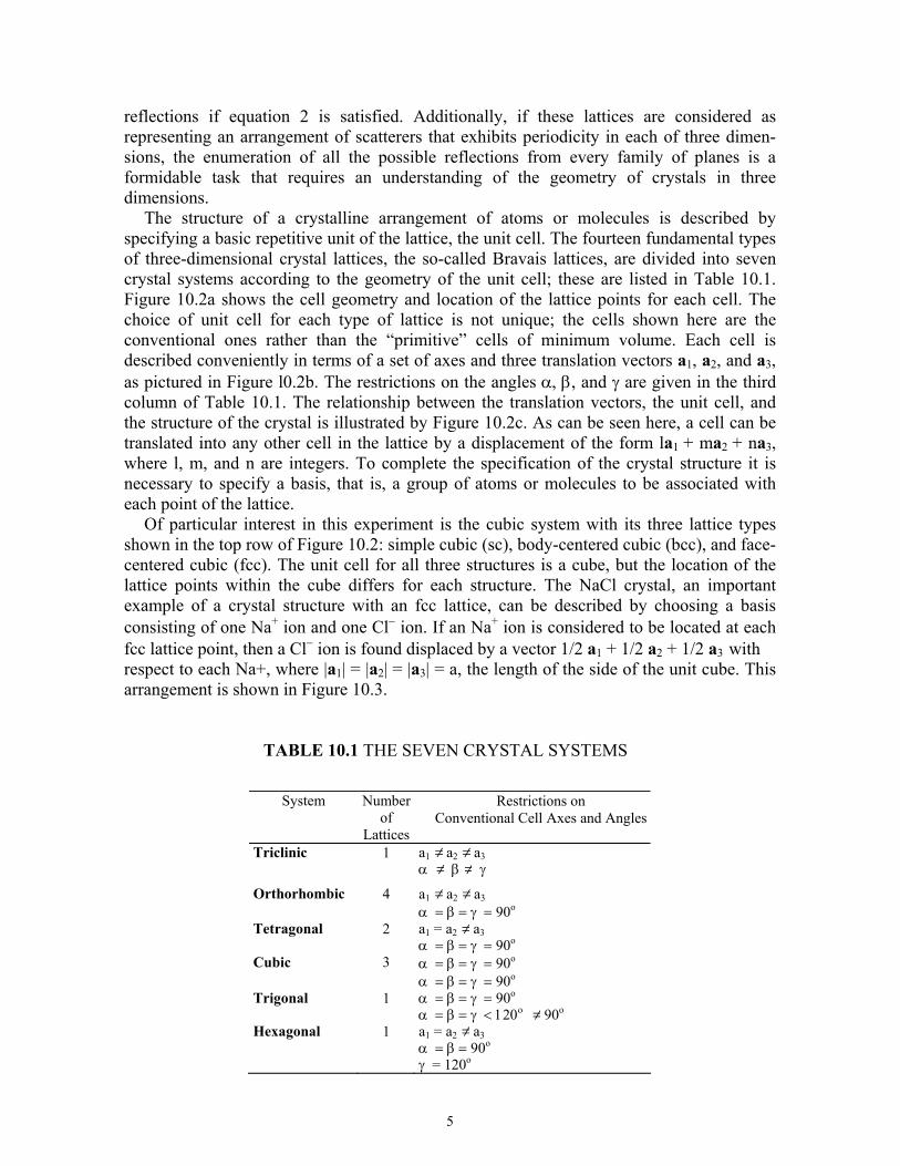
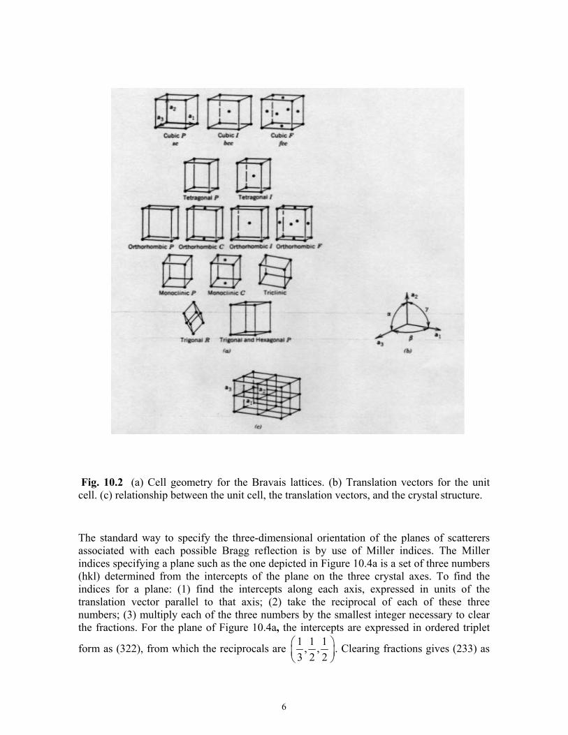
The structure of a crystalline arrangement of atoms or molecules is described by specifying a basic repetitive unit of the lattice, the unit cell. The fourteen fundamental types of three-dimensional crystal lattices, the so-called Bravais lattices, are divided into seven crystal systems according to the geometry of the unit cell; these are listed in Table 10.1. Figure 10.2a shows the cell geometry and location of the lattice points for each cell. The choice of unit cell for each type of lattice is not unique; the cells shown here are the conventional ones rather than the “primitive” cells of minimum volume. Each cell is described conveniently in terms of a set of axes and three translation vectors a1, a2, and a3, as pictured in Figure l0.2b. The restrictions on the angles α, β, and γ are given in the third column of Table 10.1. The relationship between the translation vectors, the unit cell, and the structure of the crystal is illustrated by Figure 10.2c. As can be seen here, a cell can be translated into any other cell in the lattice by a displacement of the form la1 + ma2 + na3, where l, m, and n are integers. To complete the specification of the crystal structure it is necessary to specify a basis, that is, a group of atoms or molecules to be associated with each point of the lattice.
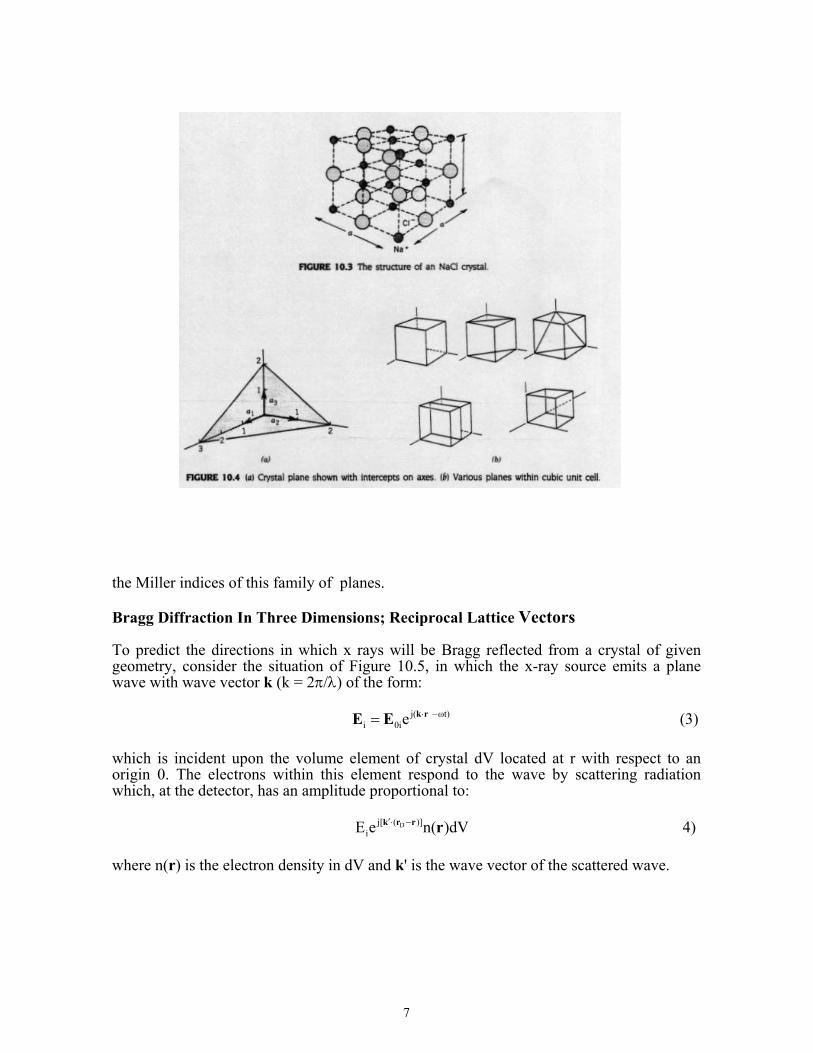
Of particular interest in this experiment is the cubic system with its three lattice types shown in the top row of Figure 10.2: simple cubic (sc), body-centered cubic (bcc), and face-centered cubic (fcc). The unit cell for all three structures is a cube, but the location of the lattice points within the cube differs for each structure. The NaCl crystal, an important example of a crystal structure with an fcc lattice, can be described by choosing a basis consisting of one Na+ ion and one Cl− ion. If an Na+ ion is considered to be located at each fcc lattice point, then a Cl− ion is found displaced by a vector 1/2 a1 + 1/2 a2 + 1/2 a3 with respect to each Na+, where |a1| = |a2| = |a3| = a, the length of the side of the unit cube. This arrangement is shown in Figure 10.3.
TABLE 10.1 THE SEVEN CRYSTAL SYSTEMS
System Numberof
Lattices
Restrictions on Conventional Cell Axes and Angles
Triclinic 1 a1 ≠ a2 ≠ a3 α ≠ β ≠ γ
Orthorhombic 4 a1 ≠ a2 ≠ a3 α = β = γ = 90o
Tetragonal 2 a1 = a2 ≠ a3 α = β = γ = 90o
Cubic 3 α = β = γ = 90o α = β = γ = 90o
Trigonal 1 α = β = γ = 90o α = β = γ < 120ο ≠ 90o
Hexagonal 1 a1 = a2 ≠ a3 α = β = 90o γ = 120o
6
Fig. 10.2 (a) Cell geometry for the Bravais lattices. (b) Translation vectors for the unit cell. (c) relationship between the unit cell, the translation vectors, and the crystal structure.
The standard way to specify the three-dimensional orientation of the planes of scatterers associated with each possible Bragg reflection is by use of Miller indices. The Miller indices specifying a plane such as the one depicted in Figure 10.4a is a set of three numbers (hkl) determined from the intercepts of the plane on the three crystal axes. To find the indices for a plane: (1) find the intercepts along each axis, expressed in units of the translation vector parallel to that axis; (2) take the reciprocal of each of these three numbers; (3) multiply each of the three numbers by the smallest integer necessary to clear the fractions. For the plane of Figure 10.4a, the intercepts are expressed in ordered triplet
form as (322), from which the reciprocals are 1 1 1, ,3 2 2
⎛ ⎞⎜ ⎟⎝ ⎠
. Clearing fractions gives (233) as
7
the Miller indices of this family of planes.
Bragg Diffraction In Three Dimensions; Reciprocal Lattice Vectors To predict the directions in which x rays will be Bragg reflected from a crystal of given geometry, consider the situation of Figure 10.5, in which the x-ray source emits a plane wave with wave vector k (k = 2π/λ) of the form: j( ωt)
i 0ie⋅ −= k rE E (3)
which is incident upon the volume element of crystal dV located at r with respect to an origin 0. The electrons within this element respond to the wave by scattering radiation which, at the detector, has an amplitude proportional to: Dj[ ( )]
iE e n( )dV′⋅ −k r r r 4) where n(r) is the electron density in dV and k' is the wave vector of the scattered wave.

8
Ignoring both the time dependence and the constant phase ′ ⋅ Dk r , the behavior of the amplitude of the scattered wave E, at the detector is given by:
j[( - ) ]n( )e dV′ ⋅∝ k k r
sE r . (5) The amplitude of the radiation at the detector due to scattering by the entire crystal is proportional to a quantity obtained by performing a volume integral of equation 5 over the electron distribution of the crystal. The result is the scattering amplitude F: j( )F= dV n( )e− ⋅∫ ∆k rr (6) where ′∆ ≡ −k k k is called the scattering vector. To obtain from equation 6 the values of ∆k for which there will be strong Bragg reflections, it is necessary to Fourier analyze the electron density function n(r). This is done by writing n(r) as a sum: j( )n( )= n e ⋅∑ G r
GG
r (7)
where the nG values are possibly complex and the summation ranges over all possible reciprocal lattice vectors G, which we now define as:
hkl 1 2 3= h + k + lG b b b . (8) Each combination of integers (hkl) specifies a different G. The vectors b1, b2, and b3 constitute a basis for the reciprocal lattice and are defined in terms of the crystal translation vectors:
9
2 3 3 1 11 2
1 2 3 1 2 3 1 2 3
2π 2π 2π× × ×
= = =⋅ × ⋅ × ⋅ ×
23
a a a a a ab b ba a a a a a a a a
(9)
We can invert the sum in equation 7 by the standard procedures of Fourier analysis to obtain an expression for nG, the Fourier coefficient corresponding to G:
1 j( )
Ccell
n V dV n( )e− − ⋅= ∫ G rG r (10)
where VC is the volume of the unit cell over which the integral is to be done.
Using the expansion of equation 7 for n(r) in the expression for the scattering amplitude F of equation 6 gives us a useful form for F:
j[( k) ]
G crystal
F dV n e −∆ ⋅= ∑ ∫ G rG . (11)
Each term in the above sum contains an exponential which, if its argument is nonzero,
oscillates in such a way that integrating over the crystal volume gives zero for that term. Thus, the only way F can be nonzero, so that a reflection can occur, is if the scattering vector ∆k happens to equal one of the G values, making the exponential equal to unity for one term of the sum. Hence, a necessary condition on ∆k = (k'− k) for the occurrence of a Bragg reflection is:
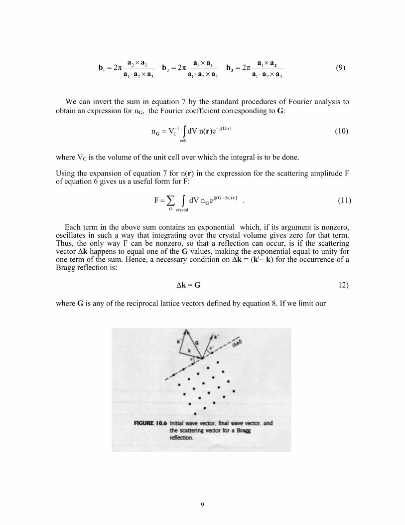
∆k = G 12) where G is any of the reciprocal lattice vectors defined by equation 8. If we limit our
10
consideration to elastic (coherent) scattering in which the wavelength is unaltered, we have the additional restriction: k' = k . (13) An example of a Bragg reflection satisfying the conditions of equations 12 and 13 is illustrated in Figure 10.6, where G, the scattering vector for this reflection, is drawn perpendicular to the reflecting plane (hkl). It is straightforward to show that the conditions expressed by equations 12 and 13 for Bragg reflections imply the two-dimensional form of the specular reflection law of equation 2. Rewriting equation 12 as: k' = k + G (14) and taking the squared magnitude of both sides gives: 2 2 2k k G 2′ = + + ⋅k G . 15) Applying the condition of equation 13 and writing (with reference to Figure 10.6) ⋅k G as −kG sinθ gives: 2k sinθ = G . 16) Recall that G depends upon the Miller indices (hkl) and so G = Ghkl and is perpendicular to the plane (hkl) doing the reflecting. It is possible to show that the spacing between planes (hkl) is given by dhkl = 2π/|Ghkl|. Thus
hklhkl
2π Gd
= 17)
for the relationship between dhkl and G. Using this to eliminate G in equation 16 and inserting the definition of the wave vector k yields the Bragg law: 2 dhkl sin θ = λ 18) as in equation 2 above. In this form the diffraction order index n no longer appears if the full sequence of Miller indices is employed since, for example, a first-order line corresponding to (222) spacing is the same as a second order (n = 2) line from the (111) planes. The spacing dhkl between parallel planes denoted by a particular set of indices (hkl) is found by calculating the length of a perpendicular from the origin to the nearest plane of the set. Standard geometry leads to the general result for cubic lattices:
hkl 2 2 2
ad =h +k +l
11
where a is the lattice constant. The preceding discussion of the space and reciprocal lattices and their relationship to the scattering amplitude not only yields a more general interpretation of the Bragg law, as derived in a simple way from Figure 10.1, but also gives us information with regard to the expected intensities of the reflections from different sets of planes (hkl). In particular, the conditions cited above for Bragg reflections are necessary but not sufficient, and some of the reflections permitted by equation 18 will be absent because of the possibility of destructive interference between waves scattered by atoms in the same cell. The discussion of this feature of Bragg reflection requires a further examination of the scattering amplitude of equation 11 and a brief discussion of form and structure factors. Structure Factor and Form Factor If equation 12 is satisfied so that for some G, ∆k = G, then the exponential appearing in the expression for the scattering amplitude F in equation 11 is just unity, and F (denoted by FG for this particular G) is then given by: G GF n dV= ∫ (19) where the integration is performed over the entire volume of the crystal. Substituting for nG, the Fourier coefficient of n(r) given by equation 10, gives an expression for the scattering amplitude in terms of the electron distribution within a single cell:
j( )GF =N dV n( )e
cell
− ⋅⎡ ⎤⎢ ⎥⎣ ⎦∫ r G r (20)
where N is the number of cells in the crystal and the expression within the square brackets is called the structure factor SG. The electron density function n(r) is often most con-veniently broken up into chunks associated with each of the atoms contained within the cell, which is the region of integration in equation 20. If this is done, then this integral can be expressed as a simple sum:
i-j( )G G iF =NS =N f e
i
⋅⎡ ⎤⎢ ⎥⎣ ⎦∑ G r 21)
in which the fi are known as form factors for the atoms and the sum is over all atoms in the cell located at positions ri ; each fi is effectively a portion of the integral in equation 20 over the charge distribution associated with the ith atom. The value of FG for any G(hkl), determines whether there will be a reflection corresponding to the atomic plane (hkl) and, hence, to ∆k = G(hkl).
12
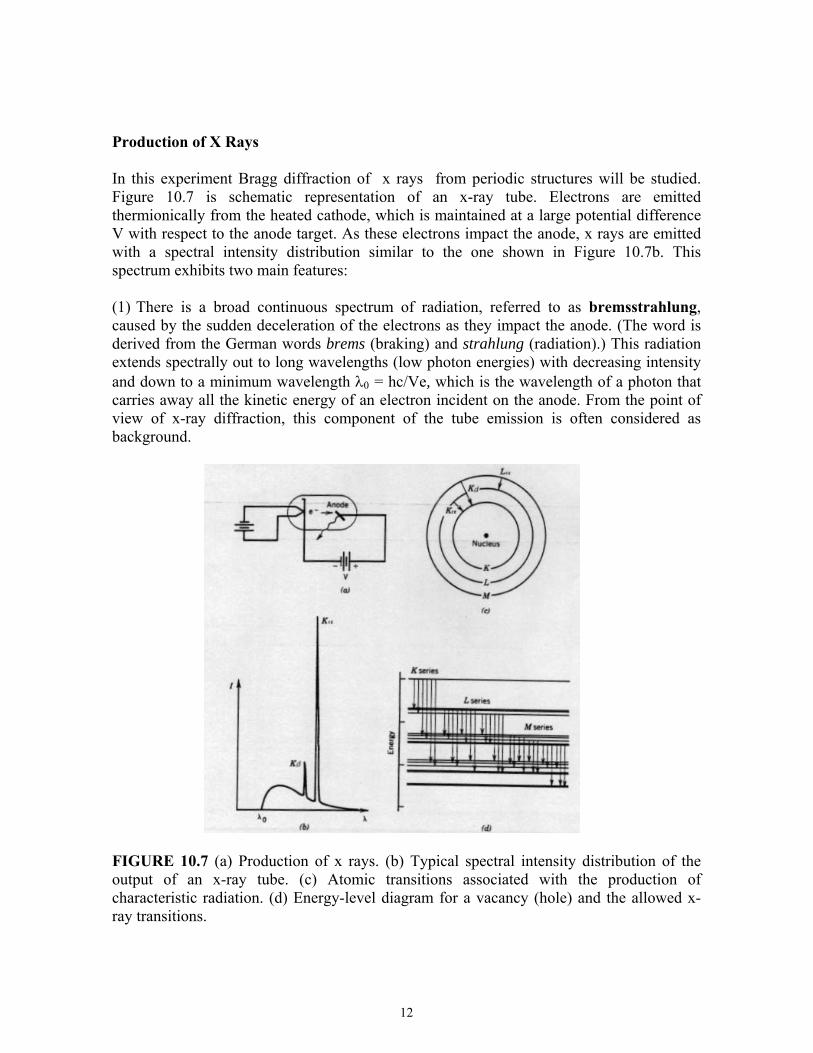
Production of X Rays In this experiment Bragg diffraction of x rays from periodic structures will be studied. Figure 10.7 is schematic representation of an x-ray tube. Electrons are emitted thermionically from the heated cathode, which is maintained at a large potential difference V with respect to the anode target. As these electrons impact the anode, x rays are emitted with a spectral intensity distribution similar to the one shown in Figure 10.7b. This spectrum exhibits two main features: (1) There is a broad continuous spectrum of radiation, referred to as bremsstrahlung, caused by the sudden deceleration of the electrons as they impact the anode. (The word is derived from the German words brems (braking) and strahlung (radiation).) This radiation extends spectrally out to long wavelengths (low photon energies) with decreasing intensity and down to a minimum wavelength λ0 = hc/Ve, which is the wavelength of a photon that carries away all the kinetic energy of an electron incident on the anode. From the point of view of x-ray diffraction, this component of the tube emission is often considered as background.
FIGURE 10.7 (a) Production of x rays. (b) Typical spectral intensity distribution of the output of an x-ray tube. (c) Atomic transitions associated with the production of characteristic radiation. (d) Energy-level diagram for a vacancy (hole) and the allowed x-ray transitions.
13
(2) Superimposed on the bremsstrahlung continuum is the nearly monochromatic set of x-ray lines that reflect the atomic structure of the atoms of the anode. The mechanism for the production of this characteristic radiation is suggested by Figure 10.7c. A high-energy electron impacts the anode and knocks out an inner shell electron from an anode atom. An x-ray photon is emitted when the vacancy thus created is filled by means of a downward transition made by an electron in one of the higher energy shells. The process can be represented on an energy diagram like that of Figure 10.7d, which represents the energy of an atom with a vacancy in a particular shell along with transitions allowed by the selection rules. The nomenclature for the various lines is derived from the initial and final states of the transition, as is suggested by Figure 10.7c. Note that the spin-orbit interaction, along with other relativistic effects, creates a splitting of the energy levels of the various shells according to the quantum number l, which indexes the total angular momentum. The line Kα , for example, is really a multiplet consisting of two lines (Kα1, Kα2), which are seldom resolved in x-ray diffraction work. Because of its monochromatic nature, the characteristic radiation described above is quite useful for x-ray diffraction. In this experiment the apparatus has an anode made of Mo, for which the important emission lines are Kα (λ =0.07107 nm) and Kβ (λ = 0.063225 nm). The wavelength given for the Kα radiation is a weighted average for the doublet Kα1,2. The Kβ radiation from Mo is about three times weaker than the Kα so that diffraction patterns can be made easier to interpret if the Kβ is selectively filtered out. This can be done conveniently for Mo K radiation by means of a foil made of Zr, which has an absorption edge (due to photoelectric absorption) at λ = 0.068877 nm, so that wavelengths shorter than this are selectively absorbed. A Zr foil with a thickness of 0.05mm, for example, when used as a filter for Mo K, will produce a beam with a Kα component that is about 16 times more intense than the Kβ . See Appendix B for Kα and Kβ emission lines and K edges for different elements. EXPERIMENT
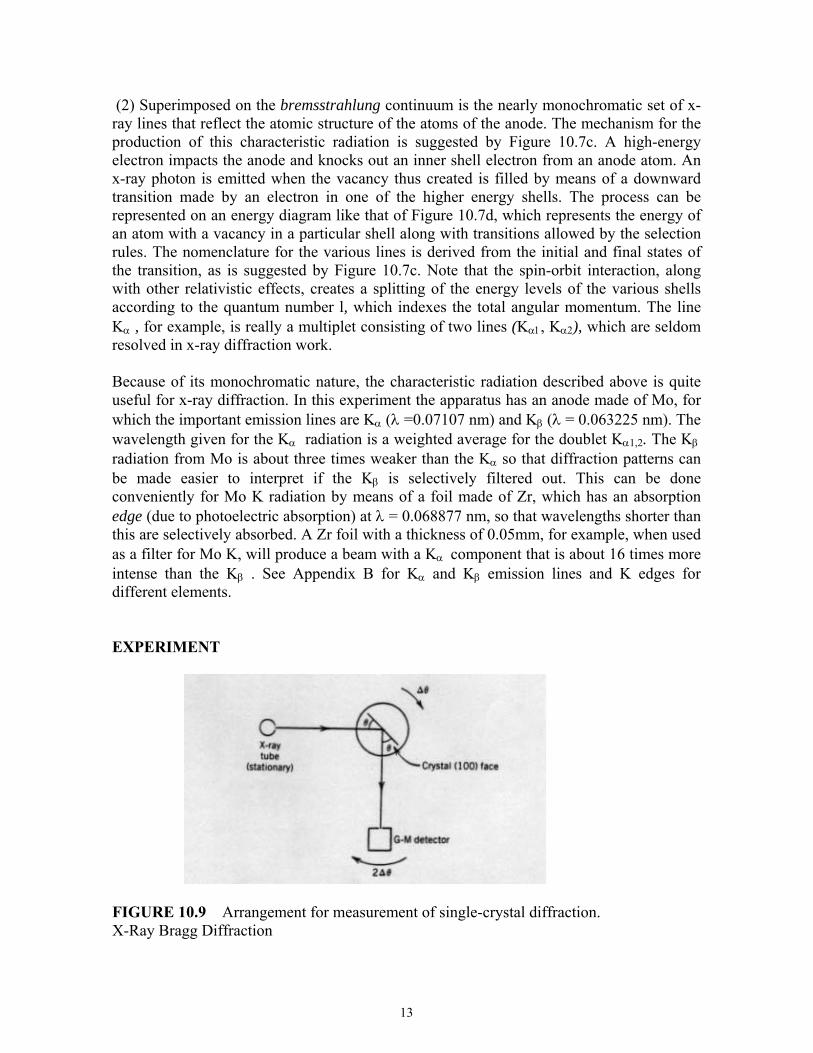
FIGURE 10.9 Arrangement for measurement of single-crystal diffraction. X-Ray Bragg Diffraction
14
Note: As with all ionizing radiation, caution should be exercised to avoid unnecessary bodily exposure. The glass panels for the x-ray apparatus are made from lead glass and there is no excess radiation outside of the apparatus. (a) Single Crystal. Mount the NaCI single crystal in the crystal mount of the diffractometer arrangement so that the (100) face is parallel to the back of mount, as shown schematically in Figure 10.9. Use an accelerating voltage of 35 kV for the x-ray tube and a current consistent with its power rating to produce a collimated beam of x rays that strikes the crystal face as shown. The diffractometer should be in θ−2θ mode, that is, the G-M detector arm should move through an angle 2θ whenever the crystal holder turns through θ so that the angles of incidence and reflection remain equal as the angle θ is scanned. 1) For values of θ within the range of motion of the diffractometer, record the detected
intensity versus θ . 2) Plot the data. Repeat the scan with a filter that has an appropriate absorption edge for
selectively attenuating the Kβ but not the Kα line. 3) Identify each observed peak with the appropriate Miller indices in the Bragg equation of
Eq. 18 and with respect to the wavelength of the radiation. Tabulate the angular positions of the peaks and, from the known wavelengths involved, calculate values for the lattice constant a. You will have to assign values of (hkl) for the observed lines. The structure factor Fhkl, for the fcc lattice, will be non-zero only if h, k, and l are either all even or all odd (See Appendix A). In general, reflections from a plane (hkl) that are permitted by the Bragg law, but for which the structure factor corresponding to Fhkl is zero, will not be detected.
4) For NaCl the edge of the unit cube of Fig. 10.3 has an accepted length of a = 0.563 nm. How does this compare with the best value derived from your data. 5) Repeat the measurements and analysis for the (100) face of a LiF crystal, for which the accepted value of a is 0.402 nm. 6) Repeat the procedure and analysis for GaAs and Si crystals. GaAs has a Zinc Blende
structure based on four symmetric covalent bonds per atom and has structure factor selection rules that are different from those of the fcc crystal. As indicated in Appendix A, the structure factors are only non-zero for the cases h + k + l = 4n, and hkl all odd. (See Appendix A). The accepted value of the lattice constant of GaAs is a = 0.565 nm. Si has the diamond cubic structure with a = 0.543 nm. Both the Zinc Blende and diamond structures can be considered as two interpenetrating FCC lattices with two atoms associated with one lattice point. These structures are therefore based on a face centered cubic lattice with eight atoms per unit cell. The GaAs sample has a (100) face and the two silicon samples have (100) and (111) faces. However, both the GaAs and (111) Si samples are cut several degrees off the crystal planes and use of the apparatus in Bragg mode will require that a sample rocking curve first be done in order to align the sample holder along the appropriate crystal plane. The instructor will show you the

15
direction of the cut and how to store the new calibration constants in the apparatus microprocessor.
Appendix A: Structure Functions The structure function i-j( )
G G iF =NS =N f ei
⋅⎡ ⎤⎢ ⎥⎣ ⎦∑ G r from Eq. 21 depends on the atomic
scattering form factors fi and the Miller indices h, k, l describing the scattering planes. The observed X-Ray intensity will be proportional to 2
G|F | . To keep track of the dependence on the Miller indices write FG as Fhkl and look at the results for some particular crystal structures. For a NaCl type face centered cubic crystal the structure factors are given by: hkl all even Fhkl = 4(fCl + fNa)
hkl all odd Fhkl = 4(fCl - fNa) hkl mixed Fhkl = 0 Note that the all odd case will give almost zero since the scattering form factors for Na
and Cl are almost identical. Thus the selection rules indicate that only the hkl all even Bragg peaks will be observed for the face centered cubic crystal.
Silicon and Gallium Arsenide have the zinc blende (ZnS) structure which also has a
face centered cubic basis cell, but different locations for the second constituent. The structure functions take the four forms:
h + k + l = 4n F2
hkl = 16(fZn + fS)2 h +k + l = 2(2n + 1) F2
hkl = 16(fZn − fS)2 hkl all odd F2
hkl = 16(f2Zn + f2
S) hkl mixed F2
hkl = 0 For silicon, the Zn and S species are identical, so only the first and third conditions will give observable Bragg peaks. The same will be almost exactly true for GaAs since Ga and As have almost identical scattering form factors.

16