abstract - open repositoryarizona.openrepository.com/arizona/bitstream/10150/555566/1/azu... ·...
TRANSCRIPT

Engineering Senior Design Project: DuctedUnmanned Aerial Vehicle Development
Item Type text; Electronic Thesis
Authors Scheber, Robert Thomas
Publisher The University of Arizona.
Rights Copyright © is held by the author. Digital access to this materialis made possible by the University Libraries, University of Arizona.Further transmission, reproduction or presentation (such aspublic display or performance) of protected items is prohibitedexcept with permission of the author.
Download date 15/07/2018 09:06:49
Link to Item http://hdl.handle.net/10150/555566
ABSTRACT
Team 1313 of the Honeywell sponsored Unmanned Aerial Vehicle Development (UAV) project
completed the following report during the Fall 2013 and Spring 2014 semesters as part of ENGR 498A/B.
The main purpose of the project was to investigate the potential benefits of a ducted UAV versus a non-
ducted UAV. The product was initially designed for use by emergency responders such as firefighting
crews. The team was also responsible for updating the electronic and avionic systems as well as
redesigning a more stable flight platform.
Team 1313 converted the original two motor UAV to a four motor quad copter design. The team also
upgraded the electronics and flight software. The following report displays Team 1313’s success in
developing the ducted UAV system and details the different design components, software architecture,
graphical user interface, design analysis, acceptance testing, and challenges.
TEAM MEMBER ROLES AND RESPONSIBILITIES
ROBERT SHEBER (MECHANICAL ENGINEERING) – Robert was the team leader and was responsible for
establishing and adhering to overall project planning, deadlines, and budgets. He was also responsible
for communicating with the Honeywell sponsor as well as contributing to the design of the UAV.
KYLE CREEK (MECHANICAL ENGINEERING) – Kyle was responsible for investigating the use of a
parachute recovery deployment system as well as contributing to the overall design of the UAV. He was
also in charge of keeping the Engineering Notebook current and documenting all meetings and project
milestones.
BRENT HATCH (MECHANICAL ENGINEERING) – Brent was responsible for a heavy majority of the
mechanical re-design of the airframe and associated components. He was also the team purchasing lead
which entailed filing purchase request forms to the AME office and communicating with outside
vendors.
NICK GARCIA (MECHANICAL ENGINEERING) - Nick was responsible for investigating the use of a
parachute recovery deployment system as well as contributing to the overall design of the UAV.
SERGIO ORTIZ (SYSTEMS ENGINEERING) – Sergio was responsible for the overall system interface of the
sub systems of the UAV. He also contributed to the overall design of the UAV and assisted with the
electronics of the UAV.
HUMBERTO VERDUGO (ELECTRICAL ENGINEERING) – Humberto was responsible for the electronics and
wiring design of the UAV. He was responsible for establishing communication of the UAV with the
software and graphical user interface. He also contributed to the overall design of the UAV.
1
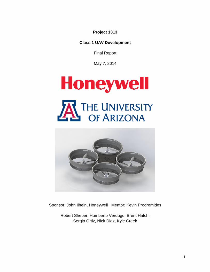
Project 1313
Class 1 UAV Development
Final Report
May 7, 2014
Sponsor: John Ilhein, Honeywell Mentor: Kevin Prodromides
Robert Sheber, Humberto Verdugo, Brent Hatch,
Sergio Ortiz, Nick Diaz, Kyle Creek
2
Contents 1. Introduction ............................................................................................................................ 3
Scope of the document ................................................................................................... 3
Changes made since Critical Design Review.................................................................. 3
Problem statement, background information................................................................... 4
Scope of project: objectives and limitations .................................................................... 5
What the product is expected to do ................................................................................ 5
Description of customer .................................................................................................. 5
2. System Requirements ............................................................................................................ 5
3. Brief Summary of PDR Results .............................................................................................. 6
4. Top-level Design of Final Design Concept ............................................................................. 8
5. Subsystem/Sub-assembly and Interface Design (Hardware) .................................................. 9
R/C Components ............................................................................................................ 9
Flight Components ........................................................................................................10
Video Feed Components ...............................................................................................11
Mechanical Hardware ....................................................................................................12
6. Algorithm Description and Interface Document (Software) ....................................................15
7. Analysis ................................................................................................................................25
8. Development Plan and Implementation .................................................................................26
9. Requirements Review / Acceptance Test Results / Performance ..........................................27
10. Closure ...............................................................................................................................30
Challenges ....................................................................................................................31
Recommendations.........................................................................................................32
References ...............................................................................................................................32
Appendices ...............................................................................................................................32
Engineering Drawings ...................................................................................................32
Bill of Materials and Suppliers .......................................................................................37
Budget ...........................................................................................................................38
Project Management .....................................................................................................39
3
1. Introduction
Scope of the document
This document provides an overview of the Senior Design Project of Team 1313, a Honeywell
Class 1 Unmanned Aerial Vehicle (UAV) . A description of the project, its objectives, and how
those objectives were accomplished is demonstrated. Details of the final product are included,
as well as conclusions and recommendations of the team.
Changes made since Critical Design Review
Vehicle Recover System: In the CDR it is stated the recovery system of the vehicle will be that
of a servo controlled spring released parachute recovery system. After extensive prototyping
and testing the following was determined:
● The parachute system in its entirety proved to be very heavy. Weight is a vital factor in
the construction process and the addition of the recovery system would compromise the
battery life and load capacity of the UAV.
● Real estate also became an issue as space is limited on the platform on which the
electronic components sit.
● The deployment system of the parachute system proved to be quite timely. It was
calculated the approximate release time for the parachute was at an altitude of
approximately 60 ft.
● The parachute protruded from the main body housing well above that of the UAV ducts.
With the parachute housing component open to the air free stream, the avionics system
is forced to adjust to maintain equilibrium. In high winds this would likely cause unstable
flight; the chief requirement of the project.
● It was concluded the parachute system was inefficient for the system design, as it was
too massive, required great heights for effective deployment and altered the flight
behavior of the vehicle. To ensure safe recovery of the vehicle, a Global Positioning
System (GPS) will be installed in the vehicle with accompanying software modifications
to set a geographic location in which the system is set to return to upon system failure.
This feature has not yet been installed by Team 1313, although its implementation into
the system is simple.
Changes in the optic system: At the time of the CDR the optic system for attachment to the
UAV was currently undecided. After budget and technical specification analysis, it was
determined that the GoPro Hero 3 white would offer the highest quality for the lowest price as
an optical system for the vehicle.
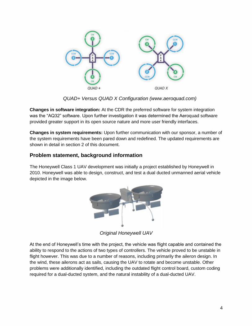
Changes in flight configuration: Flight configurations are intensive of the Aeroquad 32 flight
control board. The flight configuration is dependent on the orientation of the flight control board
with respect to the ducts. During the CDR it was determined that the flight configuration would
be in a “+” formation. It has since changed to the “x” configuration as the positioning of avionics
and optics system were more efficient in this configuration.
4
QUAD+ Versus QUAD X Configuration (www.aeroquad.com)
Changes in software integration: At the CDR the preferred software for system integration
was the “AQ32” software. Upon further investigation it was determined the Aeroquad software
provided greater support in its open source nature and more user friendly interfaces.
Changes in system requirements: Upon further communication with our sponsor, a number of
the system requirements have been pared down and redefined. The updated requirements are
shown in detail in section 2 of this document.
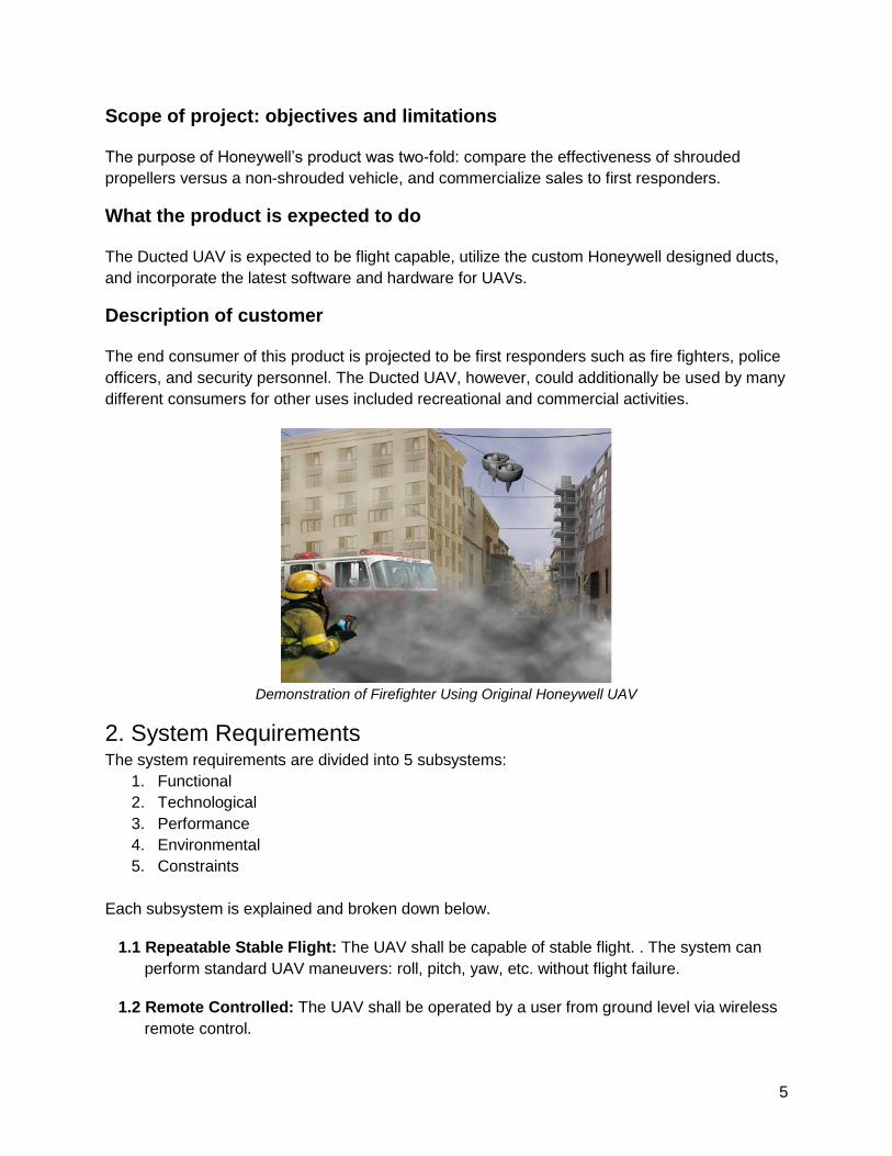
Problem statement, background information
The Honeywell Class 1 UAV development was initially a project established by Honeywell in
2010. Honeywell was able to design, construct, and test a dual ducted unmanned aerial vehicle
depicted in the image below.
Original Honeywell UAV
At the end of Honeywell’s time with the project, the vehicle was flight capable and contained the
ability to respond to the actions of two types of controllers. The vehicle proved to be unstable in
flight however. This was due to a number of reasons, including primarily the aileron design. In
the wind, these ailerons act as sails, causing the UAV to rotate and become unstable. Other
problems were additionally identified, including the outdated flight control board, custom coding
required for a dual-ducted system, and the natural instability of a dual-ducted UAV.
5
Scope of project: objectives and limitations
The purpose of Honeywell’s product was two-fold: compare the effectiveness of shrouded
propellers versus a non-shrouded vehicle, and commercialize sales to first responders.
What the product is expected to do
The Ducted UAV is expected to be flight capable, utilize the custom Honeywell designed ducts,
and incorporate the latest software and hardware for UAVs.
Description of customer
The end consumer of this product is projected to be first responders such as fire fighters, police
officers, and security personnel. The Ducted UAV, however, could additionally be used by many
different consumers for other uses included recreational and commercial activities.
Demonstration of Firefighter Using Original Honeywell UAV
2. System Requirements The system requirements are divided into 5 subsystems:
1. Functional
2. Technological
3. Performance
4. Environmental
5. Constraints
Each subsystem is explained and broken down below.
1.1 Repeatable Stable Flight: The UAV shall be capable of stable flight. . The system can
perform standard UAV maneuvers: roll, pitch, yaw, etc. without flight failure.
1.2 Remote Controlled: The UAV shall be operated by a user from ground level via wireless
remote control.
6
1.3 Video Feed: The system shall capture video during flight.
2.1 Upgrade Old Avionics: The outdated flight control board shall be replaced by the
Aeroquad STM-32 flight control board.
2.2 Improve Battery Mounting Design: The system shall have a new and improved battery
mounting design. The mounting design will need to survive external forces experienced
during flight test. It shall also protect and secure the battery pack.
2.3 Live Video Feed: The UAV camera shall be able to transmit live video feed
3.1 Take Off / Landing: The UAV shall be able to take off and land safely and without failure
3.2 Modular Design for Flight Control Board: The system shall be compatible with the
updated models of the Aeroquad STM flight control boards.
4.1 Radio Communication: The system shall maintain exclusive communication with the
remote control system
4.2 Stable Flight in Wind: The UAV shall maintain stable flight as per 1.1.1 and 1.1.2 under
wind conditions up to 10 miles per hour
5.1 Code Language: Code must be written in C and C++.
5.2 UAV Classification: The system shall keep classification of a “micro UAV” as described
by “Classification of Unmanned Aerial Vehicles”.
5.3 Use Honeywell Duct Structure: The UAV shall incorporate the ducts provided by
Honeywell.
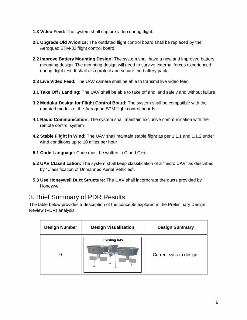
3. Brief Summary of PDR Results The table below provides a description of the concepts explored in the Preliminary Design
Review (PDR) analysis.
Design Number Design Visualization Design Summary
0
Current system design.
7
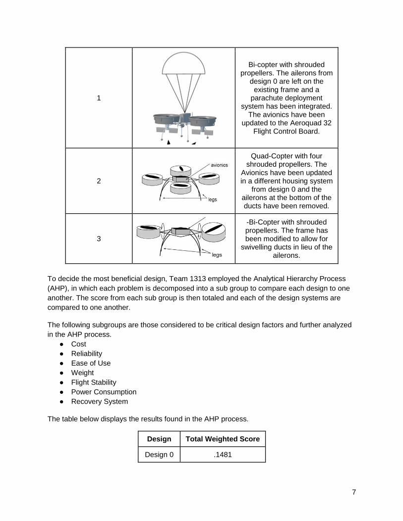
1
Bi-copter with shrouded propellers. The ailerons from
design 0 are left on the existing frame and a
parachute deployment system has been integrated.
The avionics have been updated to the Aeroquad 32
Flight Control Board.
2
Quad-Copter with four shrouded propellers. The
Avionics have been updated in a different housing system
from design 0 and the ailerons at the bottom of the ducts have been removed.
3
-Bi-Copter with shrouded propellers. The frame has been modified to allow for
swivelling ducts in lieu of the ailerons.
To decide the most beneficial design, Team 1313 employed the Analytical Hierarchy Process
(AHP), in which each problem is decomposed into a sub group to compare each design to one
another. The score from each sub group is then totaled and each of the design systems are
compared to one another.
The following subgroups are those considered to be critical design factors and further analyzed
in the AHP process.
● Cost
● Reliability
● Ease of Use
● Weight
● Flight Stability
● Power Consumption
● Recovery System
The table below displays the results found in the AHP process.
Design Total Weighted Score
Design 0 .1481
8
Design 1 .2189
Design 2 .4500
Design 3 .2108
The preferred vehicle design was determined to be the quadcopter, “Design 2”. The results
discovered in the AHP process as to why this is the best option is explained below.
● The quadcopter design is a tested and proven technology. The two added propellers
improve the stability and performance of the UAV.
● The quadcopter design will also improve the ease of use of the system. Four propellers
allow for better maneuverability and intuitive user controlling.
● The quadcopter design allows for easy implementation of open-source software that
has already been developed for such copters. Honeywell specified the use of the open-
source Aeroquad software. This software would provide for all the necessary functions
of the UAV without additional manual coding.
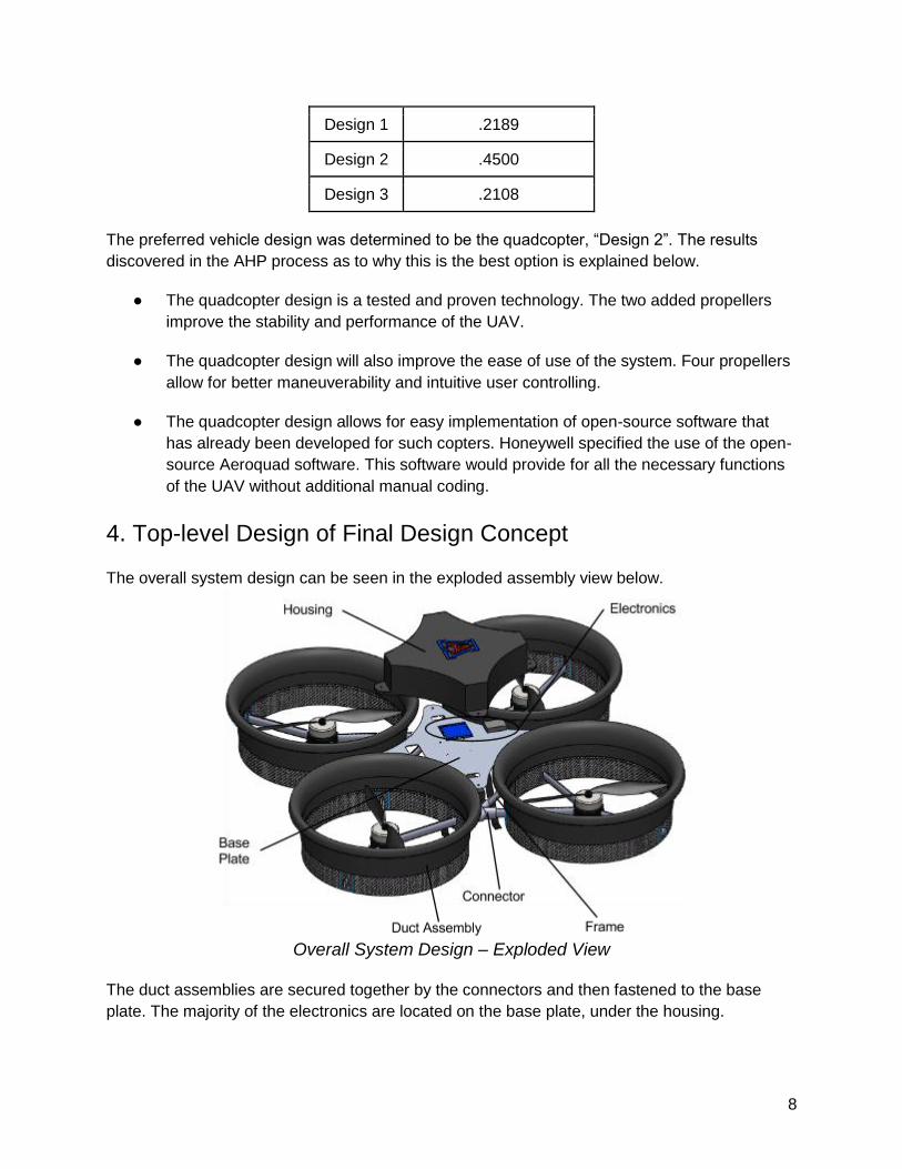
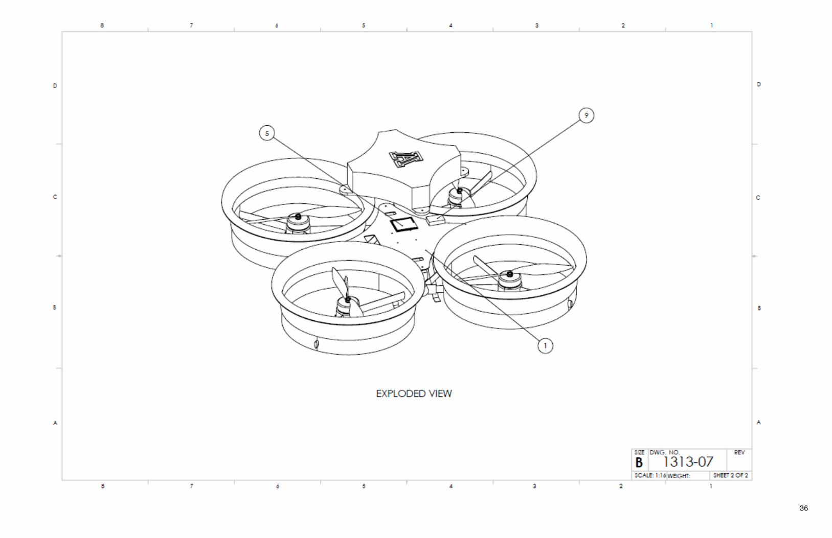
4. Top-level Design of Final Design Concept
The overall system design can be seen in the exploded assembly view below.
Overall System Design – Exploded View
The duct assemblies are secured together by the connectors and then fastened to the base
plate. The majority of the electronics are located on the base plate, under the housing.
9
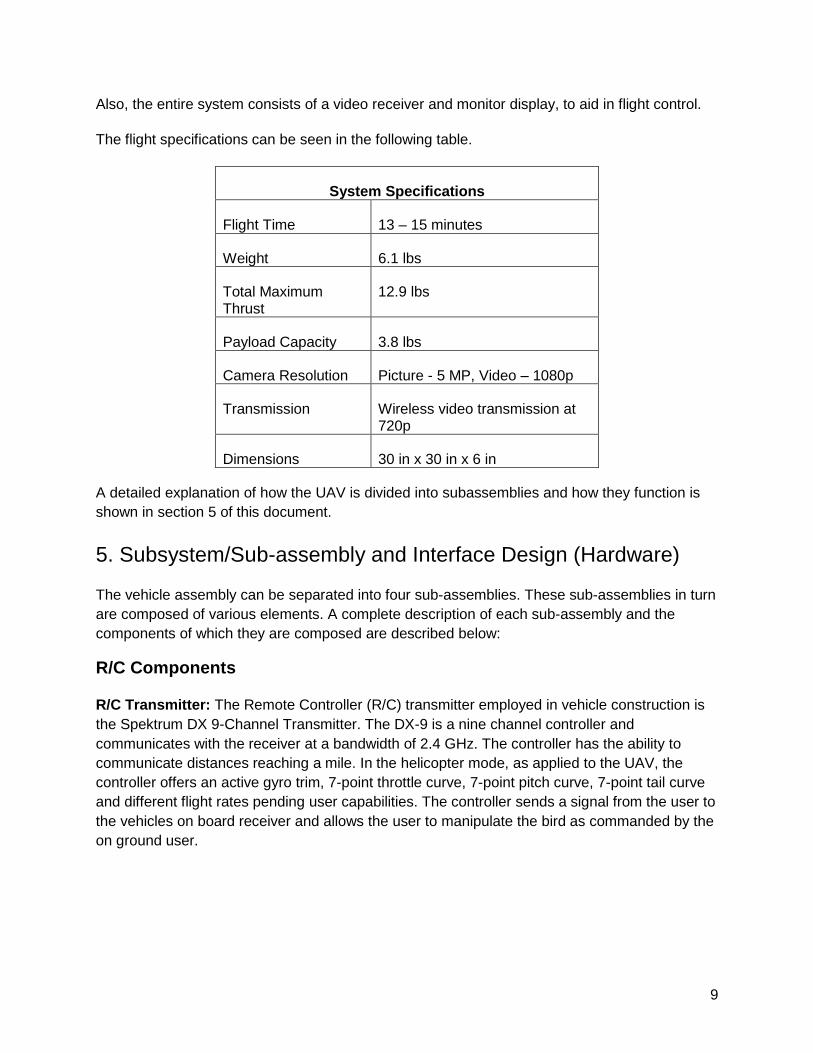
Also, the entire system consists of a video receiver and monitor display, to aid in flight control.
The flight specifications can be seen in the following table.
System Specifications
Flight Time 13 – 15 minutes
Weight 6.1 lbs
Total Maximum Thrust
12.9 lbs
Payload Capacity 3.8 lbs
Camera Resolution Picture - 5 MP, Video – 1080p
Transmission Wireless video transmission at 720p
Dimensions 30 in x 30 in x 6 in
A detailed explanation of how the UAV is divided into subassemblies and how they function is
shown in section 5 of this document.
5. Subsystem/Sub-assembly and Interface Design (Hardware)
The vehicle assembly can be separated into four sub-assemblies. These sub-assemblies in turn
are composed of various elements. A complete description of each sub-assembly and the
components of which they are composed are described below:
R/C Components
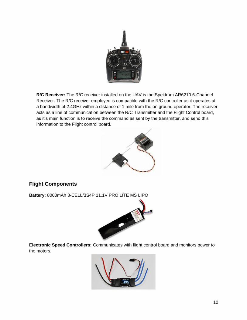
R/C Transmitter: The Remote Controller (R/C) transmitter employed in vehicle construction is
the Spektrum DX 9-Channel Transmitter. The DX-9 is a nine channel controller and
communicates with the receiver at a bandwidth of 2.4 GHz. The controller has the ability to
communicate distances reaching a mile. In the helicopter mode, as applied to the UAV, the
controller offers an active gyro trim, 7-point throttle curve, 7-point pitch curve, 7-point tail curve
and different flight rates pending user capabilities. The controller sends a signal from the user to
the vehicles on board receiver and allows the user to manipulate the bird as commanded by the
on ground user.
10
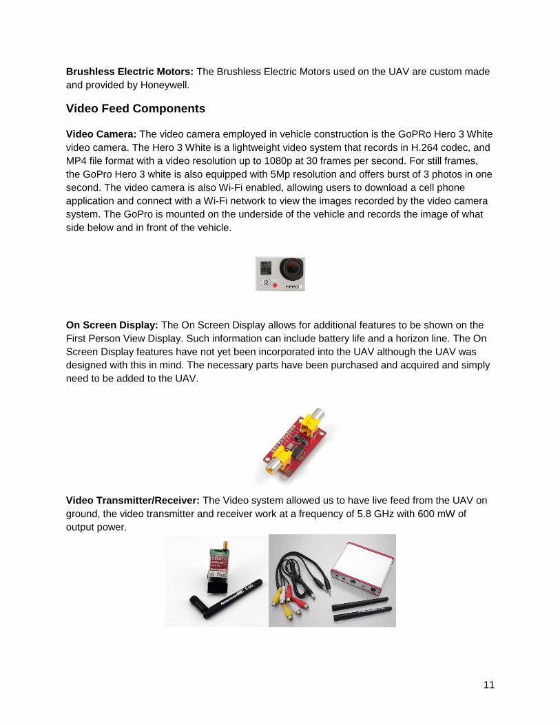
R/C Receiver: The R/C receiver installed on the UAV is the Spektrum AR6210 6-Channel
Receiver. The R/C receiver employed is compatible with the R/C controller as it operates at
a bandwidth of 2.4GHz within a distance of 1 mile from the on ground operator. The receiver
acts as a line of communication between the R/C Transmitter and the Flight Control board,
as it’s main function is to receive the command as sent by the transmitter, and send this
information to the Flight control board.
Flight Components
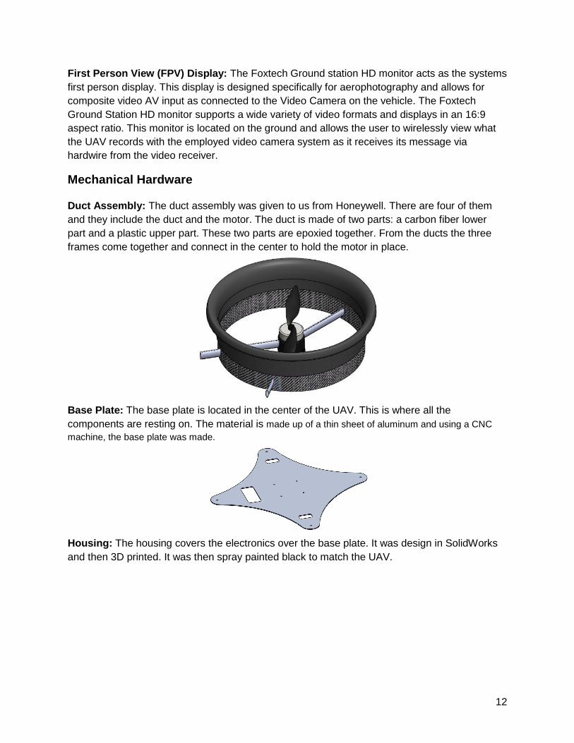
Battery: 8000mAh 3-CELL/3S4P 11.1V PRO LITE MS LIPO
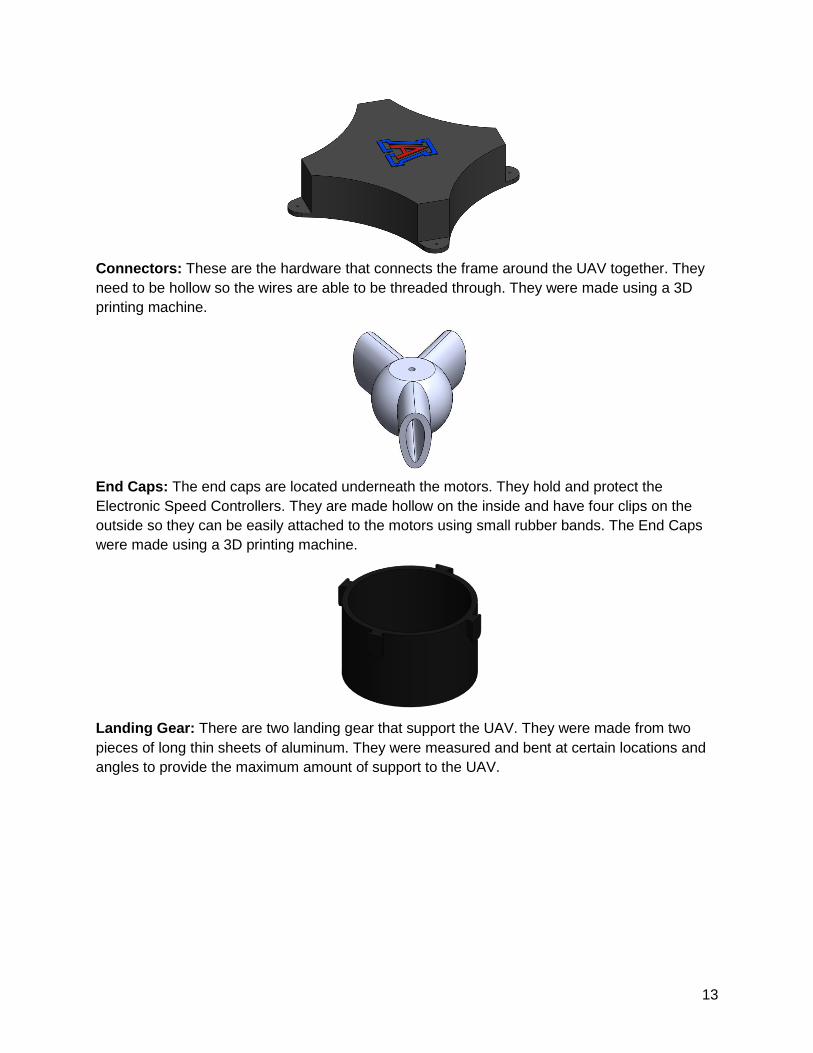
Electronic Speed Controllers: Communicates with flight control board and monitors power to
the motors.
11
Brushless Electric Motors: The Brushless Electric Motors used on the UAV are custom made
and provided by Honeywell.
Video Feed Components
Video Camera: The video camera employed in vehicle construction is the GoPRo Hero 3 White
video camera. The Hero 3 White is a lightweight video system that records in H.264 codec, and
MP4 file format with a video resolution up to 1080p at 30 frames per second. For still frames,
the GoPro Hero 3 white is also equipped with 5Mp resolution and offers burst of 3 photos in one
second. The video camera is also Wi-Fi enabled, allowing users to download a cell phone
application and connect with a Wi-Fi network to view the images recorded by the video camera
system. The GoPro is mounted on the underside of the vehicle and records the image of what
side below and in front of the vehicle.
On Screen Display: The On Screen Display allows for additional features to be shown on the
First Person View Display. Such information can include battery life and a horizon line. The On
Screen Display features have not yet been incorporated into the UAV although the UAV was
designed with this in mind. The necessary parts have been purchased and acquired and simply
need to be added to the UAV.
Video Transmitter/Receiver: The Video system allowed us to have live feed from the UAV on
ground, the video transmitter and receiver work at a frequency of 5.8 GHz with 600 mW of
output power.
12
First Person View (FPV) Display: The Foxtech Ground station HD monitor acts as the systems
first person display. This display is designed specifically for aerophotography and allows for
composite video AV input as connected to the Video Camera on the vehicle. The Foxtech
Ground Station HD monitor supports a wide variety of video formats and displays in an 16:9
aspect ratio. This monitor is located on the ground and allows the user to wirelessly view what
the UAV records with the employed video camera system as it receives its message via
hardwire from the video receiver.
Mechanical Hardware
Duct Assembly: The duct assembly was given to us from Honeywell. There are four of them
and they include the duct and the motor. The duct is made of two parts: a carbon fiber lower
part and a plastic upper part. These two parts are epoxied together. From the ducts the three
frames come together and connect in the center to hold the motor in place.
Base Plate: The base plate is located in the center of the UAV. This is where all the
components are resting on. The material is made up of a thin sheet of aluminum and using a CNC
machine, the base plate was made.
Housing: The housing covers the electronics over the base plate. It was design in SolidWorks
and then 3D printed. It was then spray painted black to match the UAV.
13
Connectors: These are the hardware that connects the frame around the UAV together. They
need to be hollow so the wires are able to be threaded through. They were made using a 3D
printing machine.
End Caps: The end caps are located underneath the motors. They hold and protect the
Electronic Speed Controllers. They are made hollow on the inside and have four clips on the
outside so they can be easily attached to the motors using small rubber bands. The End Caps
were made using a 3D printing machine.
Landing Gear: There are two landing gear that support the UAV. They were made from two
pieces of long thin sheets of aluminum. They were measured and bent at certain locations and
angles to provide the maximum amount of support to the UAV.
14
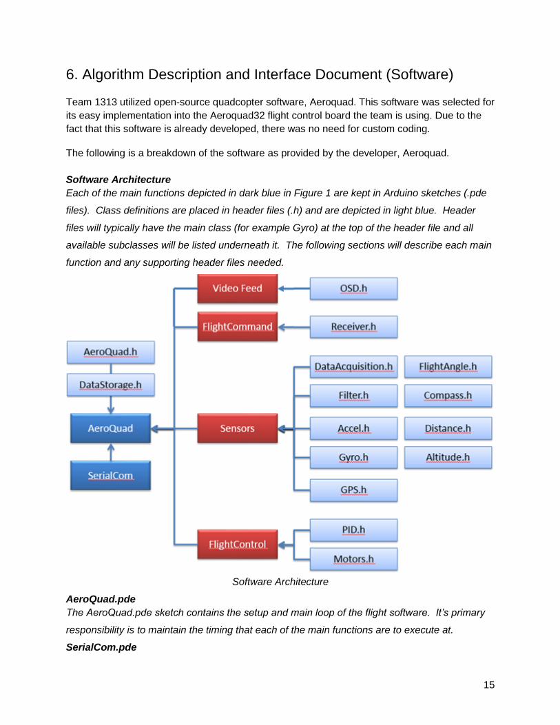
The figure below provides a pictorial representation of and provides insight to the architecture of
the vehicle subsystems and their communications with one another as described in the sub-
assembly breakdown mentioned above.
Component Subsystem Overview
15
6. Algorithm Description and Interface Document (Software)
Team 1313 utilized open-source quadcopter software, Aeroquad. This software was selected for
its easy implementation into the Aeroquad32 flight control board the team is using. Due to the
fact that this software is already developed, there was no need for custom coding.
The following is a breakdown of the software as provided by the developer, Aeroquad.
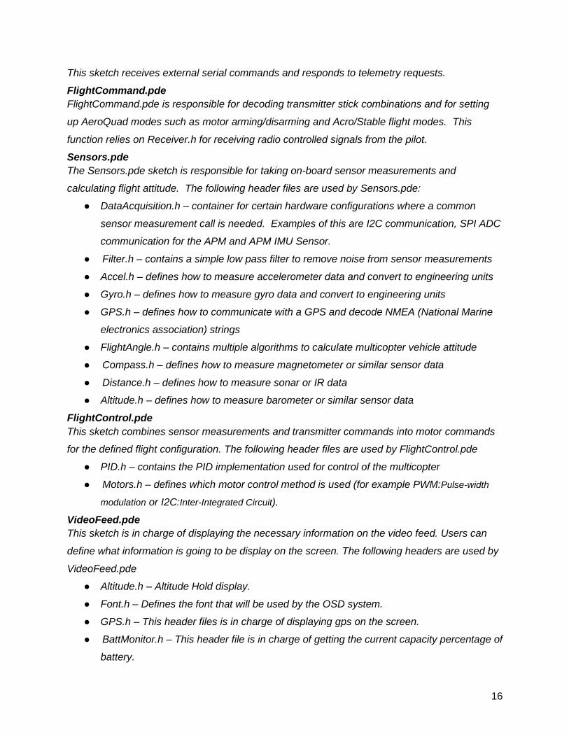
Software Architecture
Each of the main functions depicted in dark blue in Figure 1 are kept in Arduino sketches (.pde
files). Class definitions are placed in header files (.h) and are depicted in light blue. Header
files will typically have the main class (for example Gyro) at the top of the header file and all
available subclasses will be listed underneath it. The following sections will describe each main
function and any supporting header files needed.
Software Architecture
AeroQuad.pde
The AeroQuad.pde sketch contains the setup and main loop of the flight software. It’s primary
responsibility is to maintain the timing that each of the main functions are to execute at.
SerialCom.pde
16
This sketch receives external serial commands and responds to telemetry requests.
FlightCommand.pde
FlightCommand.pde is responsible for decoding transmitter stick combinations and for setting
up AeroQuad modes such as motor arming/disarming and Acro/Stable flight modes. This
function relies on Receiver.h for receiving radio controlled signals from the pilot.
Sensors.pde
The Sensors.pde sketch is responsible for taking on-board sensor measurements and
calculating flight attitude. The following header files are used by Sensors.pde:
● DataAcquisition.h – container for certain hardware configurations where a common
sensor measurement call is needed. Examples of this are I2C communication, SPI ADC
communication for the APM and APM IMU Sensor.
● Filter.h – contains a simple low pass filter to remove noise from sensor measurements
● Accel.h – defines how to measure accelerometer data and convert to engineering units
● Gyro.h – defines how to measure gyro data and convert to engineering units
● GPS.h – defines how to communicate with a GPS and decode NMEA (National Marine
electronics association) strings
● FlightAngle.h – contains multiple algorithms to calculate multicopter vehicle attitude
● Compass.h – defines how to measure magnetometer or similar sensor data
● Distance.h – defines how to measure sonar or IR data
● Altitude.h – defines how to measure barometer or similar sensor data
FlightControl.pde
This sketch combines sensor measurements and transmitter commands into motor commands
for the defined flight configuration. The following header files are used by FlightControl.pde
● PID.h – contains the PID implementation used for control of the multicopter
● Motors.h – defines which motor control method is used (for example PWM:Pulse-width
modulation or I2C:Inter-Integrated Circuit).
VideoFeed.pde
This sketch is in charge of displaying the necessary information on the video feed. Users can
define what information is going to be display on the screen. The following headers are used by
VideoFeed.pde
● Altitude.h – Altitude Hold display.
● Font.h – Defines the font that will be used by the OSD system.
● GPS.h – This header files is in charge of displaying gps on the screen.
● BattMonitor.h – This header file is in charge of getting the current capacity percentage of
battery.
17
Class Definitions
This section will describe each class defined in the AeroQuad Flight Software. Any new
subclasses must conform to the methods (or function calls) defined in the main class. The
header files are listed in alphabetical order below. Each section will list the available methods
or function calls used by the flight software. Please note: Only header files that defines a class
used within the flight software are listed below. There are several header files found in the top
level architecture that contain functions not organized as a class. This was done since they
typically just contain a single function call.
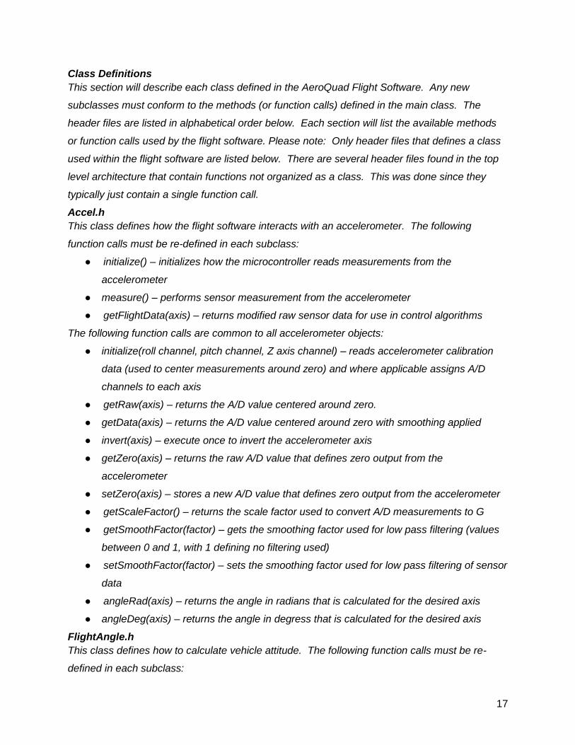
Accel.h
This class defines how the flight software interacts with an accelerometer. The following
function calls must be re-defined in each subclass:
● initialize() – initializes how the microcontroller reads measurements from the
accelerometer
● measure() – performs sensor measurement from the accelerometer
● getFlightData(axis) – returns modified raw sensor data for use in control algorithms
The following function calls are common to all accelerometer objects:
● initialize(roll channel, pitch channel, Z axis channel) – reads accelerometer calibration
data (used to center measurements around zero) and where applicable assigns A/D
channels to each axis
● getRaw(axis) – returns the A/D value centered around zero.
● getData(axis) – returns the A/D value centered around zero with smoothing applied
● invert(axis) – execute once to invert the accelerometer axis
● getZero(axis) – returns the raw A/D value that defines zero output from the
accelerometer
● setZero(axis) – stores a new A/D value that defines zero output from the accelerometer
● getScaleFactor() – returns the scale factor used to convert A/D measurements to G
● getSmoothFactor(factor) – gets the smoothing factor used for low pass filtering (values
between 0 and 1, with 1 defining no filtering used)
● setSmoothFactor(factor) – sets the smoothing factor used for low pass filtering of sensor
data
● angleRad(axis) – returns the angle in radians that is calculated for the desired axis
● angleDeg(axis) – returns the angle in degress that is calculated for the desired axis
FlightAngle.h
This class defines how to calculate vehicle attitude. The following function calls must be re-
defined in each subclass:
18
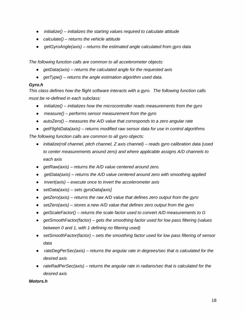
● initialize() – initializes the starting values required to calculate attitude
● calculate() – returns the vehicle attitude
● getGyroAngle(axis) – returns the estimated angle calculated from gyro data
The following function calls are common to all accelerometer objects:
● getData(axis) – returns the calculated angle for the requested axis
● getType() – returns the angle estimation algorithm used data.
Gyro.h
This class defines how the flight software interacts with a gyro. The following function calls
must be re-defined in each subclass:
● initialize() – initializes how the microcontroller reads measurements from the gyro
● measure() – performs sensor measurement from the gyro
● autoZero() – measures the A/D value that corresponds to a zero angular rate
● getFlightData(axis) – returns modified raw sensor data for use in control algorithms
The following function calls are common to all gyro objects:
● initialize(roll channel, pitch channel, Z axis channel) – reads gyro calibration data (used
to center measurements around zero) and where applicable assigns A/D channels to
each axis
● getRaw(axis) – returns the A/D value centered around zero.
● getData(axis) – returns the A/D value centered around zero with smoothing applied
● invert(axis) – execute once to invert the accelerometer axis
● setData(axis) – sets gyroData[axis]
● getZero(axis) – returns the raw A/D value that defines zero output from the gyro
● setZero(axis) – stores a new A/D value that defines zero output from the gyro
● getScaleFactor() – returns the scale factor used to convert A/D measurements to G
● getSmoothFactor(factor) – gets the smoothing factor used for low pass filtering (values
between 0 and 1, with 1 defining no filtering used)
● setSmoothFactor(factor) – sets the smoothing factor used for low pass filtering of sensor
data
● rateDegPerSec(axis) – returns the angular rate in degrees/sec that is calculated for the
desired axis
● rateRadPerSec(axis) – returns the angular rate in radians/sec that is calculated for the
desired axis
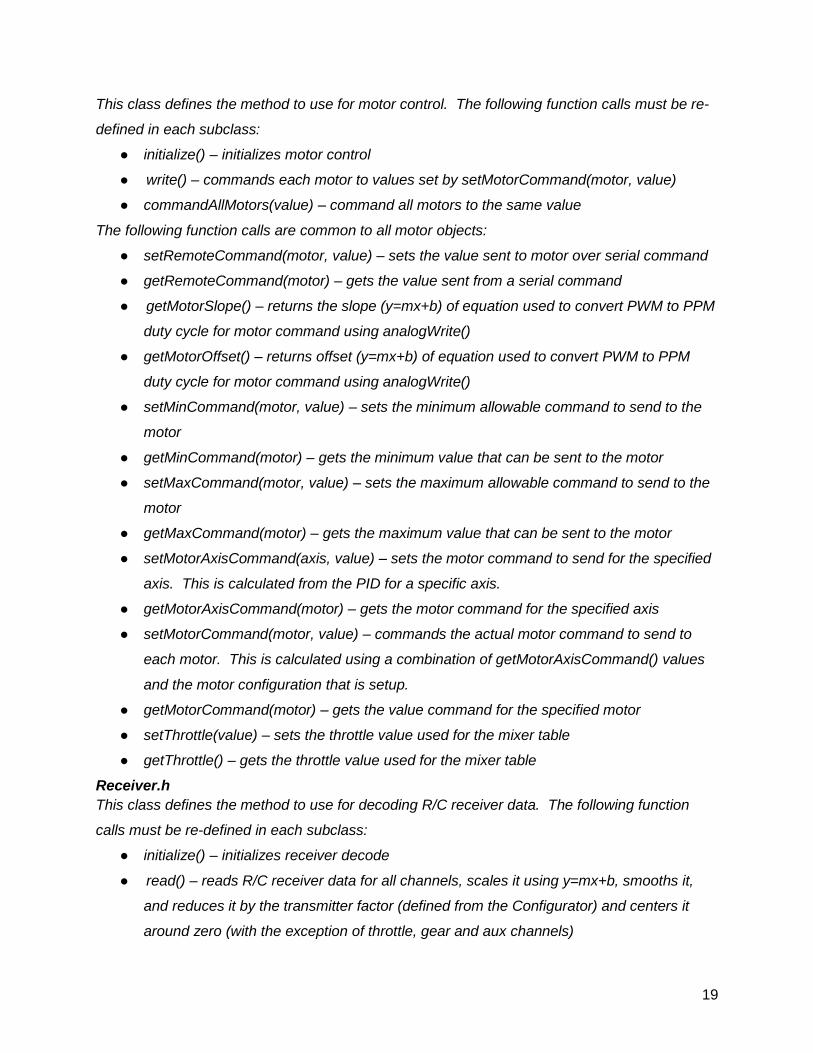
Motors.h
19
This class defines the method to use for motor control. The following function calls must be re-
defined in each subclass:
● initialize() – initializes motor control
● write() – commands each motor to values set by setMotorCommand(motor, value)
● commandAllMotors(value) – command all motors to the same value
The following function calls are common to all motor objects:
● setRemoteCommand(motor, value) – sets the value sent to motor over serial command
● getRemoteCommand(motor) – gets the value sent from a serial command
● getMotorSlope() – returns the slope (y=mx+b) of equation used to convert PWM to PPM
duty cycle for motor command using analogWrite()
● getMotorOffset() – returns offset (y=mx+b) of equation used to convert PWM to PPM
duty cycle for motor command using analogWrite()
● setMinCommand(motor, value) – sets the minimum allowable command to send to the
motor
● getMinCommand(motor) – gets the minimum value that can be sent to the motor
● setMaxCommand(motor, value) – sets the maximum allowable command to send to the
motor
● getMaxCommand(motor) – gets the maximum value that can be sent to the motor
● setMotorAxisCommand(axis, value) – sets the motor command to send for the specified
axis. This is calculated from the PID for a specific axis.
● getMotorAxisCommand(motor) – gets the motor command for the specified axis
● setMotorCommand(motor, value) – commands the actual motor command to send to
each motor. This is calculated using a combination of getMotorAxisCommand() values
and the motor configuration that is setup.
● getMotorCommand(motor) – gets the value command for the specified motor
● setThrottle(value) – sets the throttle value used for the mixer table
● getThrottle() – gets the throttle value used for the mixer table
Receiver.h
This class defines the method to use for decoding R/C receiver data. The following function
calls must be re-defined in each subclass:
● initialize() – initializes receiver decode
● read() – reads R/C receiver data for all channels, scales it using y=mx+b, smooths it,
and reduces it by the transmitter factor (defined from the Configurator) and centers it
around zero (with the exception of throttle, gear and aux channels)
20
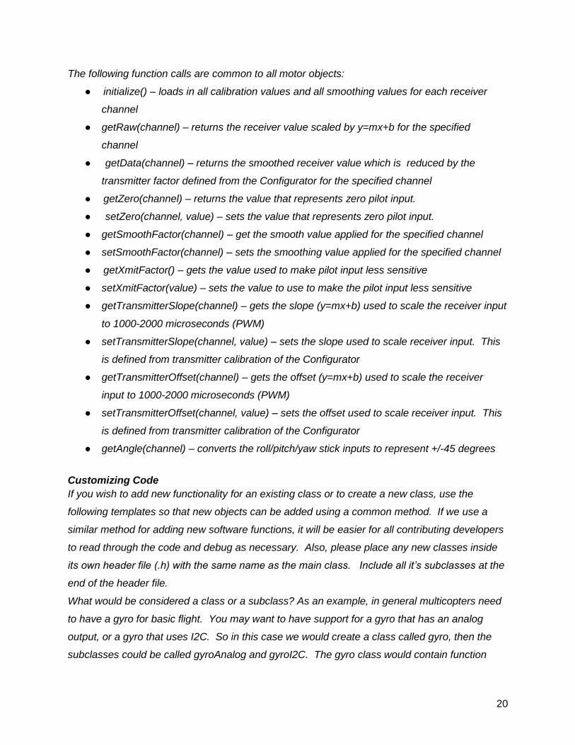
The following function calls are common to all motor objects:
● initialize() – loads in all calibration values and all smoothing values for each receiver
channel
● getRaw(channel) – returns the receiver value scaled by y=mx+b for the specified
channel
● getData(channel) – returns the smoothed receiver value which is reduced by the
transmitter factor defined from the Configurator for the specified channel
● getZero(channel) – returns the value that represents zero pilot input.
● setZero(channel, value) – sets the value that represents zero pilot input.
● getSmoothFactor(channel) – get the smooth value applied for the specified channel
● setSmoothFactor(channel) – sets the smoothing value applied for the specified channel
● getXmitFactor() – gets the value used to make pilot input less sensitive
● setXmitFactor(value) – sets the value to use to make the pilot input less sensitive
● getTransmitterSlope(channel) – gets the slope (y=mx+b) used to scale the receiver input
to 1000-2000 microseconds (PWM)
● setTransmitterSlope(channel, value) – sets the slope used to scale receiver input. This
is defined from transmitter calibration of the Configurator
● getTransmitterOffset(channel) – gets the offset (y=mx+b) used to scale the receiver
input to 1000-2000 microseconds (PWM)
● setTransmitterOffset(channel, value) – sets the offset used to scale receiver input. This
is defined from transmitter calibration of the Configurator
● getAngle(channel) – converts the roll/pitch/yaw stick inputs to represent +/-45 degrees
Customizing Code
If you wish to add new functionality for an existing class or to create a new class, use the
following templates so that new objects can be added using a common method. If we use a
similar method for adding new software functions, it will be easier for all contributing developers
to read through the code and debug as necessary. Also, please place any new classes inside
its own header file (.h) with the same name as the main class. Include all it’s subclasses at the
end of the header file.
What would be considered a class or a subclass? As an example, in general multicopters need
to have a gyro for basic flight. You may want to have support for a gyro that has an analog
output, or a gyro that uses I2C. So in this case we would create a class called gyro, then the
subclasses could be called gyroAnalog and gyroI2C. The gyro class would contain function
21
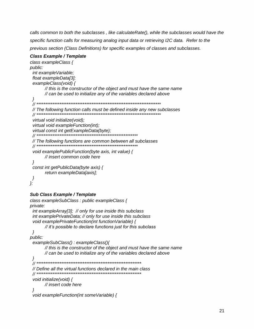
calls common to both the subclasses , like calculateRate(), while the subclasses would have the
specific function calls for measuring analog input data or retrieving I2C data. Refer to the
previous section (Class Definitions) for specific examples of classes and subclasses.
Class Example / Template
class exampleClass { public: int exampleVariable; float exampleData[3]; exampleClass(void) { // this is the constructor of the object and must have the same name // can be used to initialize any of the variables declared above } // ********************************************************************** // The following function calls must be defined inside any new subclasses // ********************************************************************** virtual void initialize(void); virtual void exampleFunction(int); virtual const int getExampleData(byte); // ********************************************************* // The following functions are common between all subclasses // ********************************************************* void examplePublicFunction(byte axis, int value) { // insert common code here } const int getPublicData(byte axis) { return exampleData[axis]; } };
Sub Class Example / Template
class exampleSubClass : public exampleClass { private: int exampleArray[3]; // only for use inside this subclass int examplePrivateData; // only for use inside this subclass void examplePrivateFunction(int functionVariable) { // it’s possible to declare functions just for this subclass } public: exampleSubClass() : exampleClass(){ // this is the constructor of the object and must have the same name // can be used to initialize any of the variables declared above } // *********************************************************** // Define all the virtual functions declared in the main class // *********************************************************** void initialize(void) { // insert code here } void exampleFunction(int someVariable) {
22
// insert code here examplePrivateFunction(someVariable); } const int getExampleData(byte axis) { // insert code here return exampleArray[axis]; } };
How to Use an Object
After you create your classes and subclasses, they can be called in the code as follows:
#include “exampleHeader.h” exampleSubClass objectName; int data = 0; int output; objectName.initialize(); objectName.exampleFunction(data); output = objectName.getExampleData(data);
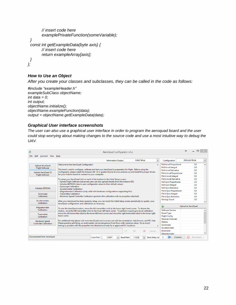
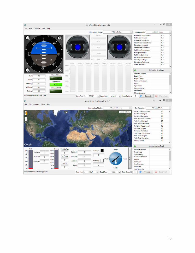
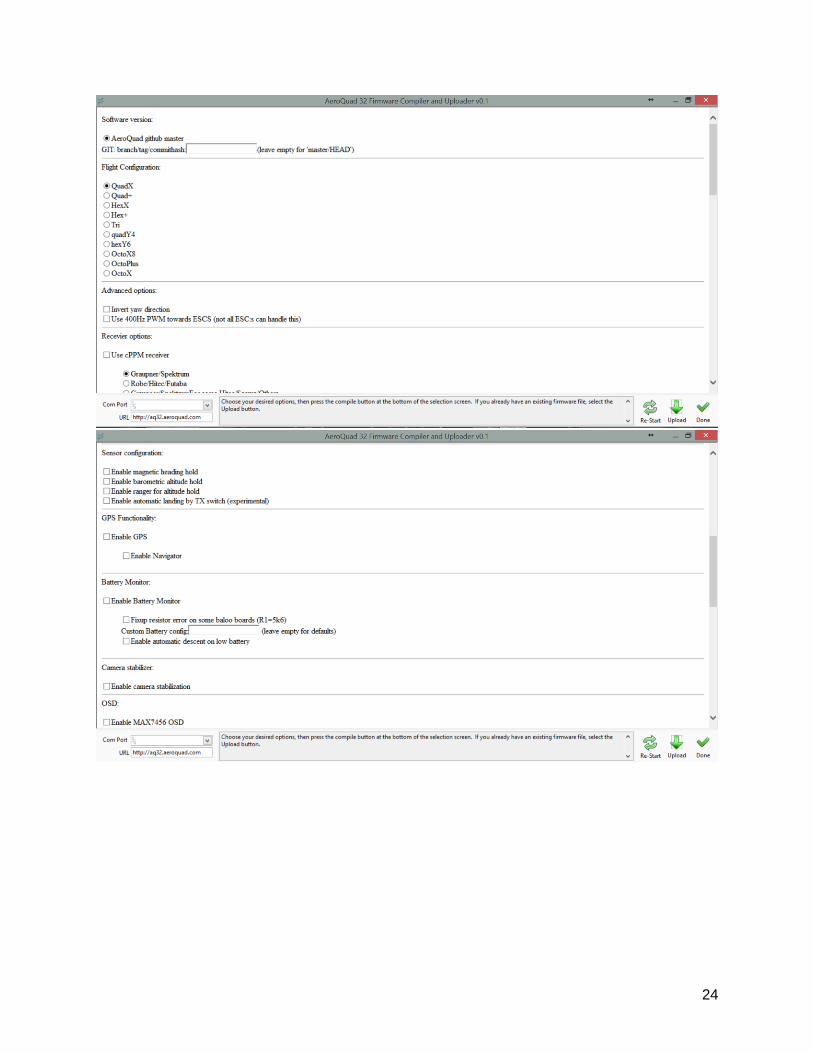
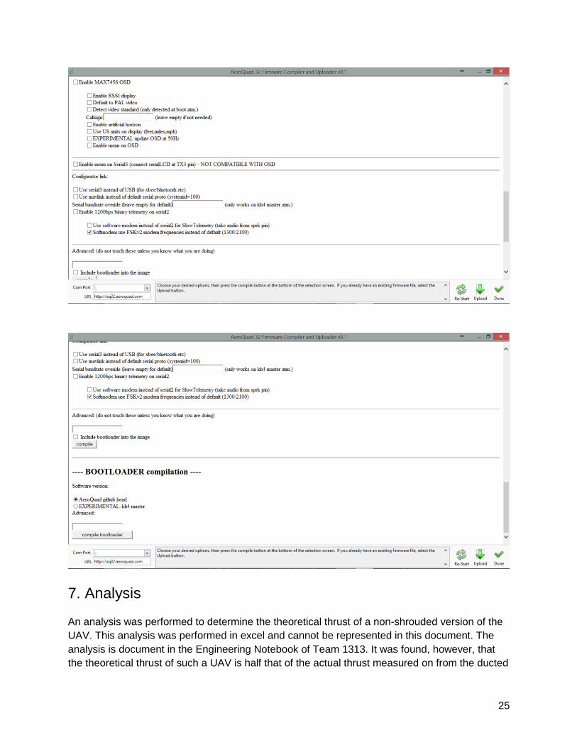
Graphical User interface screenshots
The user can also use a graphical user interface in order to program the aeroquad board and the user
could stop worrying about making changes to the source code and use a most intuitive way to debug the
UAV.
23
24
25
7. Analysis
An analysis was performed to determine the theoretical thrust of a non-shrouded version of the
UAV. This analysis was performed in excel and cannot be represented in this document. The
analysis is document in the Engineering Notebook of Team 1313. It was found, however, that
the theoretical thrust of such a UAV is half that of the actual thrust measured on from the ducted
26
UAV. Part of this thrust increase can be attributed to the ducts, which help focus the airflow and
create more thrust.
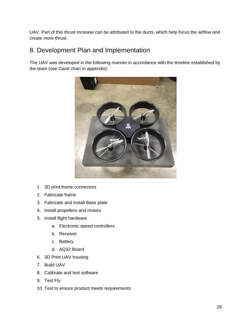
8. Development Plan and Implementation
The UAV was developed in the following manner in accordance with the timeline established by
the team (see Gantt chart in appendix):
1. 3D print frame connectors
2. Fabricate frame
3. Fabricate and install Base plate
4. Install propellers and motors
5. Install flight hardware
a. Electronic speed controllers
b. Receiver
c. Battery
d. AQ32 Board
6. 3D Print UAV housing
7. Build UAV
8. Calibrate and test software
9. Test Fly
10. Test to ensure product meets requirements
27
11. Determine UAV specifications
Every effort was made in order to build according to the Gantt chart timeline and deliver the
UAV on time on Design Day. Due to challenges that are explained in section 10, it was
necessary to rebuild the entire UAV twice. This pushed back the time that was set apart for test
flying. Regardless of these difficulties, the UAV was completed and test flown on several
occasions in order to determine whether or not the product meets the system requirements.
Videos documenting test flights and demonstrating the capabilities of the UAV can be found in
the Engineering Notebook of Team 1313.
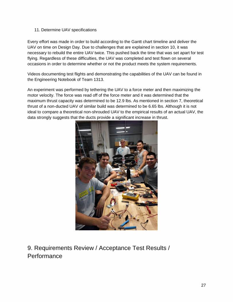
An experiment was performed by tethering the UAV to a force meter and then maximizing the
motor velocity. The force was read off of the force meter and it was determined that the
maximum thrust capacity was determined to be 12.9 lbs. As mentioned in section 7, theoretical
thrust of a non-ducted UAV of similar build was determined to be 6.65 lbs. Although it is not
ideal to compare a theoretical non-shrouded UAV to the empirical results of an actual UAV, the
data strongly suggests that the ducts provide a significant increase in thrust.
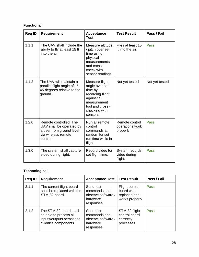
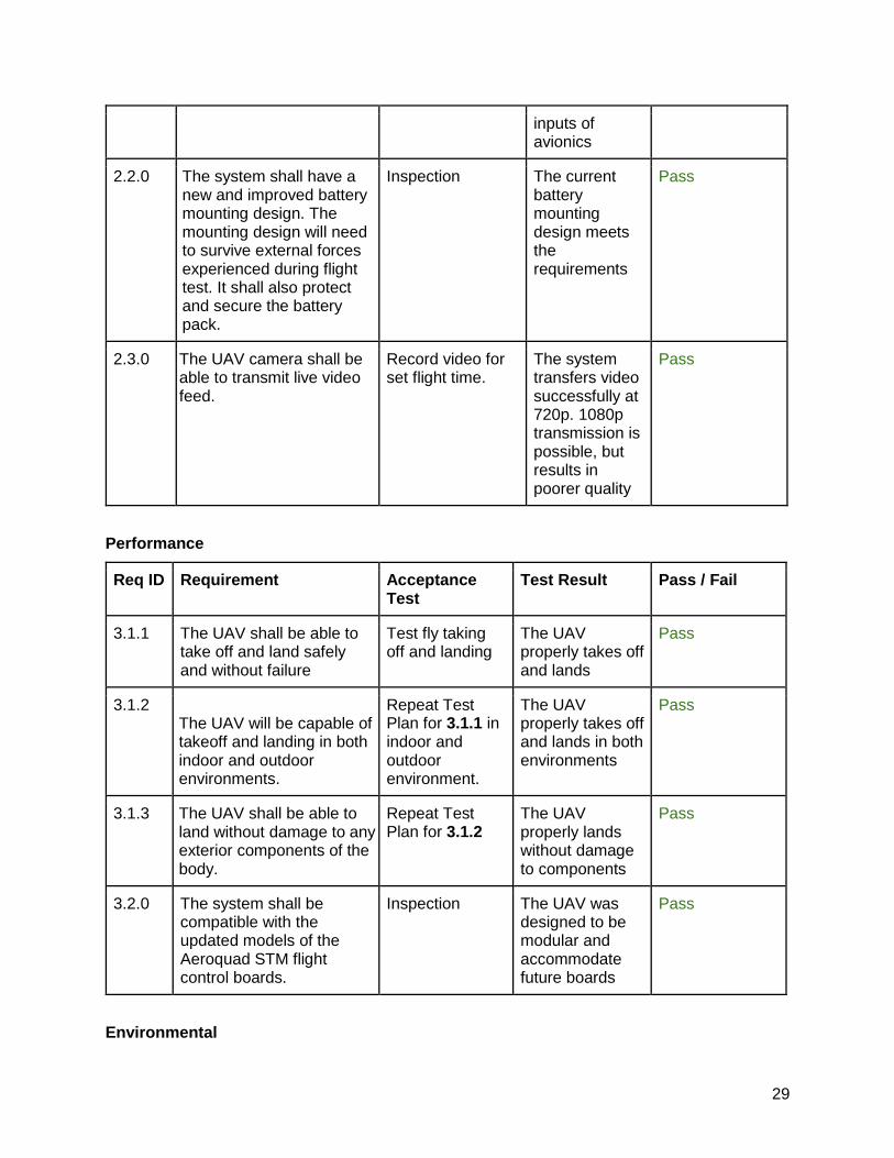
9. Requirements Review / Acceptance Test Results /
Performance
28
Functional
Req ID Requirement Acceptance Test
Test Result Pass / Fail
1.1.1 The UAV shall include the ability to fly at least 15 ft into the air.
Measure altitude / pitch over set time using physical measurements and cross - check with sensor readings.
Flies at least 15 ft into the air.
Pass
1.1.2 The UAV will maintain a parallel flight angle of +/- 45 degrees relative to the ground.
Measure flight angle over set time by recording flight against a measurement tool and cross - checking with sensors
Not yet tested Not yet tested
1.2.0 Remote controlled: The UAV shall be operated by a user from ground level via wireless remote control.
Run all remote control commands at random for set run time while in flight
Remote control operations work properly
Pass
1.3.0 The system shall capture video during flight.
Record video for set flight time.
System records video during flight.
Pass
Technological
Req ID Requirement Acceptance Test Test Result Pass / Fail
2.1.1 The current flight board shall be replaced with the STM-32 board.
Send test commands and observe software / hardware responses
Flight control board was replaced and works properly
Pass
2.1.2 The STM-32 board shall be able to process all inputs/outputs across the avionics components.
Send test commands and observe software / hardware responses
STM-32 flight control board correctly processes
Pass
29
inputs of avionics
2.2.0 The system shall have a new and improved battery mounting design. The mounting design will need to survive external forces experienced during flight test. It shall also protect and secure the battery pack.
Inspection The current battery mounting design meets the requirements
Pass
2.3.0 The UAV camera shall be able to transmit live video feed.
Record video for set flight time.
The system transfers video successfully at 720p. 1080p transmission is possible, but results in poorer quality
Pass
Performance
Req ID Requirement Acceptance Test
Test Result Pass / Fail
3.1.1 The UAV shall be able to take off and land safely and without failure
Test fly taking off and landing
The UAV properly takes off and lands
Pass
3.1.2 The UAV will be capable of takeoff and landing in both indoor and outdoor environments.
Repeat Test Plan for 3.1.1 in indoor and outdoor environment.
The UAV properly takes off and lands in both environments
Pass
3.1.3 The UAV shall be able to land without damage to any exterior components of the body.
Repeat Test Plan for 3.1.2
The UAV properly lands without damage to components
Pass
3.2.0 The system shall be compatible with the updated models of the Aeroquad STM flight control boards.
Inspection The UAV was designed to be modular and accommodate future boards
Pass
Environmental
30
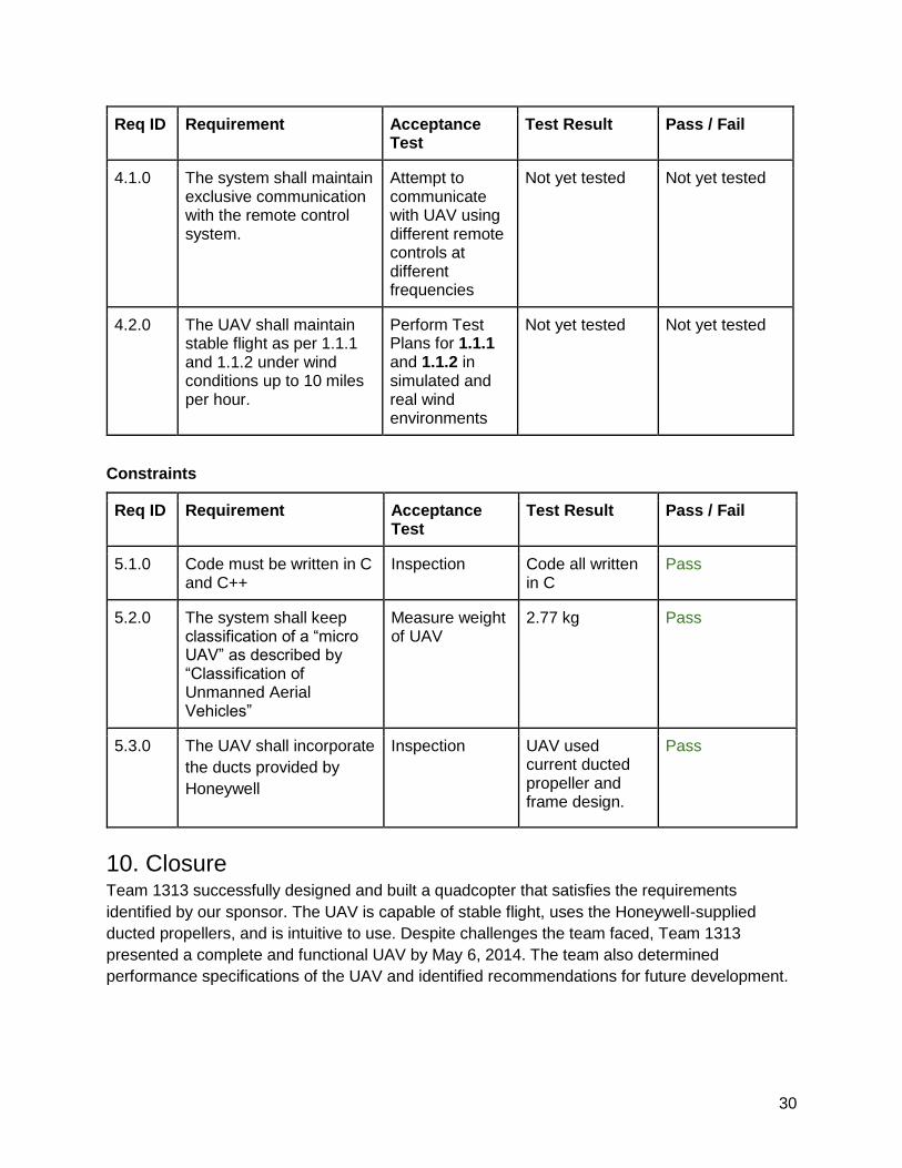
Req ID Requirement Acceptance Test
Test Result Pass / Fail
4.1.0 The system shall maintain exclusive communication with the remote control system.
Attempt to communicate with UAV using different remote controls at different frequencies
Not yet tested Not yet tested
4.2.0 The UAV shall maintain stable flight as per 1.1.1 and 1.1.2 under wind conditions up to 10 miles per hour.
Perform Test Plans for 1.1.1 and 1.1.2 in simulated and real wind environments
Not yet tested Not yet tested
Constraints
Req ID Requirement Acceptance Test
Test Result Pass / Fail
5.1.0 Code must be written in C and C++
Inspection Code all written in C
Pass
5.2.0 The system shall keep classification of a “micro UAV” as described by “Classification of Unmanned Aerial Vehicles”
Measure weight of UAV
2.77 kg Pass
5.3.0 The UAV shall incorporate
the ducts provided by
Honeywell
Inspection UAV used current ducted propeller and frame design.
Pass
10. Closure Team 1313 successfully designed and built a quadcopter that satisfies the requirements
identified by our sponsor. The UAV is capable of stable flight, uses the Honeywell-supplied
ducted propellers, and is intuitive to use. Despite challenges the team faced, Team 1313
presented a complete and functional UAV by May 6, 2014. The team also determined
performance specifications of the UAV and identified recommendations for future development.
31
Challenges
Parachute Design: In the beginning of the semester, a main goal was to provide the UAV with
a secondary recovery system such as a parachute. After designing and testing a working
parachute deployment system for over the course of 5 weeks, the system was dropped due to
various problems. The system was very large and took up a lot of valuable real estate on the
UAV, also the system would not deploy and safely land the UAV unless the UAV was over 6
stories when the system deployed. Scrapping the parachute system cost the group valuable
time that could have been spent in working on the UAV.
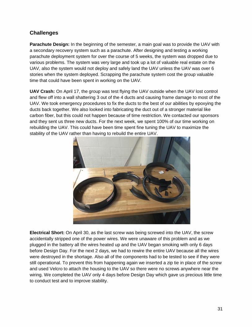
UAV Crash: On April 17, the group was test flying the UAV outside when the UAV lost control
and flew off into a wall shattering 3 out of the 4 ducts and causing frame damage to most of the
UAV. We took emergency procedures to fix the ducts to the best of our abilities by epoxying the
ducts back together. We also looked into fabricating the duct out of a stronger material like
carbon fiber, but this could not happen because of time restriction. We contacted our sponsors
and they sent us three new ducts. For the next week, we spent 100% of our time working on
rebuilding the UAV. This could have been time spent fine tuning the UAV to maximize the
stability of the UAV rather than having to rebuild the entire UAV.
Electrical Short: On April 30, as the last screw was being screwed into the UAV, the screw
accidentally stripped one of the power wires. We were unaware of this problem and as we
plugged in the battery all the wires heated up and the UAV began smoking with only 6 days
before Design Day. For the next 2 days, we had to rewire the entire UAV because all the wires
were destroyed in the shortage. Also all of the components had to be tested to see if they were
still operational. To prevent this from happening again we inserted a zip tie in place of the screw
and used Velcro to attach the housing to the UAV so there were no screws anywhere near the
wiring. We completed the UAV only 4 days before Design Day which gave us precious little time
to conduct test and to improve stability.
32
Recommendations
GPS: An old GPS that the sponsors gave us and a GPS that we bought we could not get to
work because of the noise in the shop and the lack of time we had to work with. With a GPS, we
could improve the UAV with preprogrammed flights.
Onscreen Display: With the onscreen display we could add different features like battery life of
the UAV, flight velocity, flight altitude, and GPS location.
Improved Ducts: The plastic part of the ducts need to be improved with a stronger material.
When the UAV crashed it showed how brittle the ducts are. A strong recommendation for the
material to use on the ducts would be carbon fiber because after the crash the carbon fiber was
not damaged.
Parachute Deployment System: This system was abandoned early in the semester because
of the amount of time that it costing us. With more time the Parachute Deployment System
could have been perfected and added into the UAV.
Improve Connection between Frame and Base Plate: The current connection that we are
using is zip ties, which is mostly because a quick and easy solution needed to be found. With
more time a better connection system could have easily been made.
Improve Landing Gear: The current landing gear is not perfect. A new set of landing gear is
needed. One that will support the duct in all directions rather than just side to side. Also a more
stable landing gear is needed.
Further Testing: Because of the two major accidents, we lost a lot of time. This time was
dedicated to doing further testing on the UAV. There are many System Requirement test that
we did not get to test but have confidence that the UAV would be able to complete.
Modularity: The UAV has great potential to be modular. There not many things in the UAV that
are permanently attached. Most of the components in the UAV can easily upgraded.
References
www.Aeroquad.com
Several pictures provided by manufacturers websites
Appendices
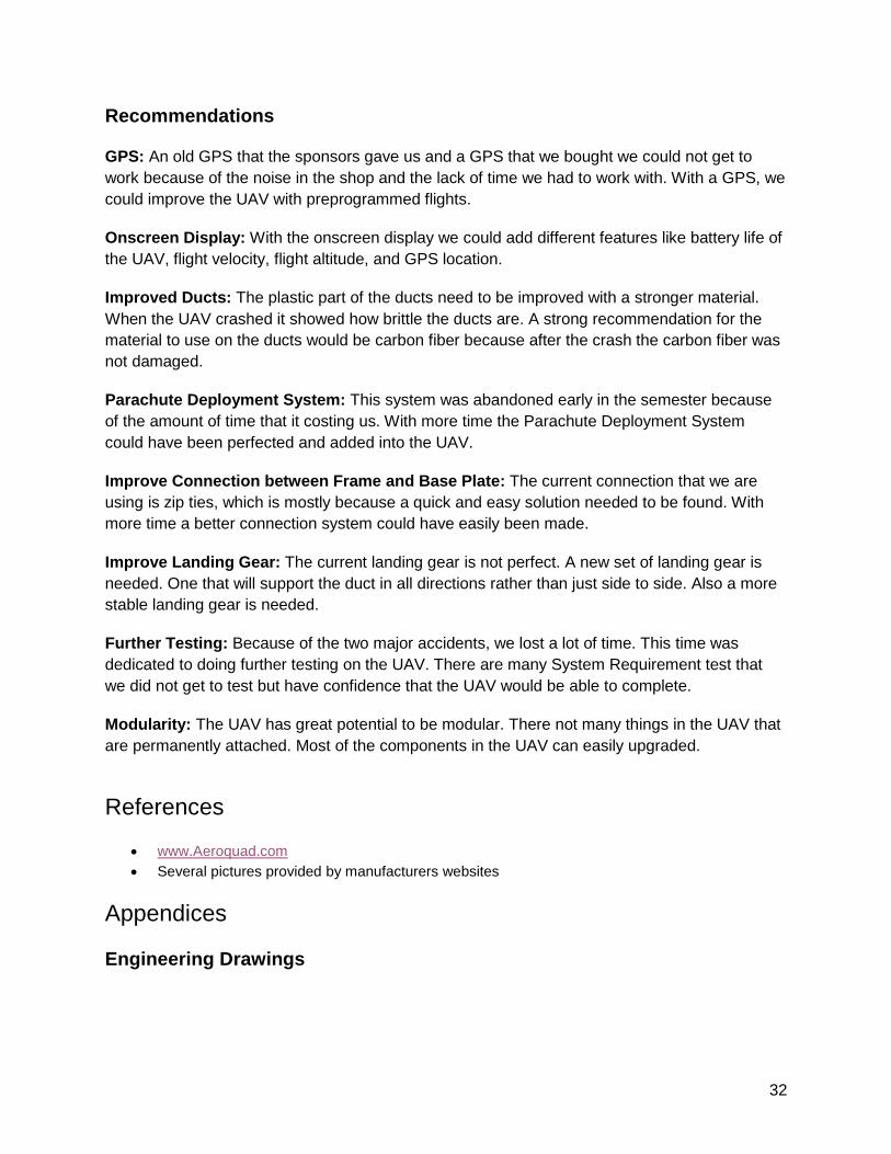
Engineering Drawings
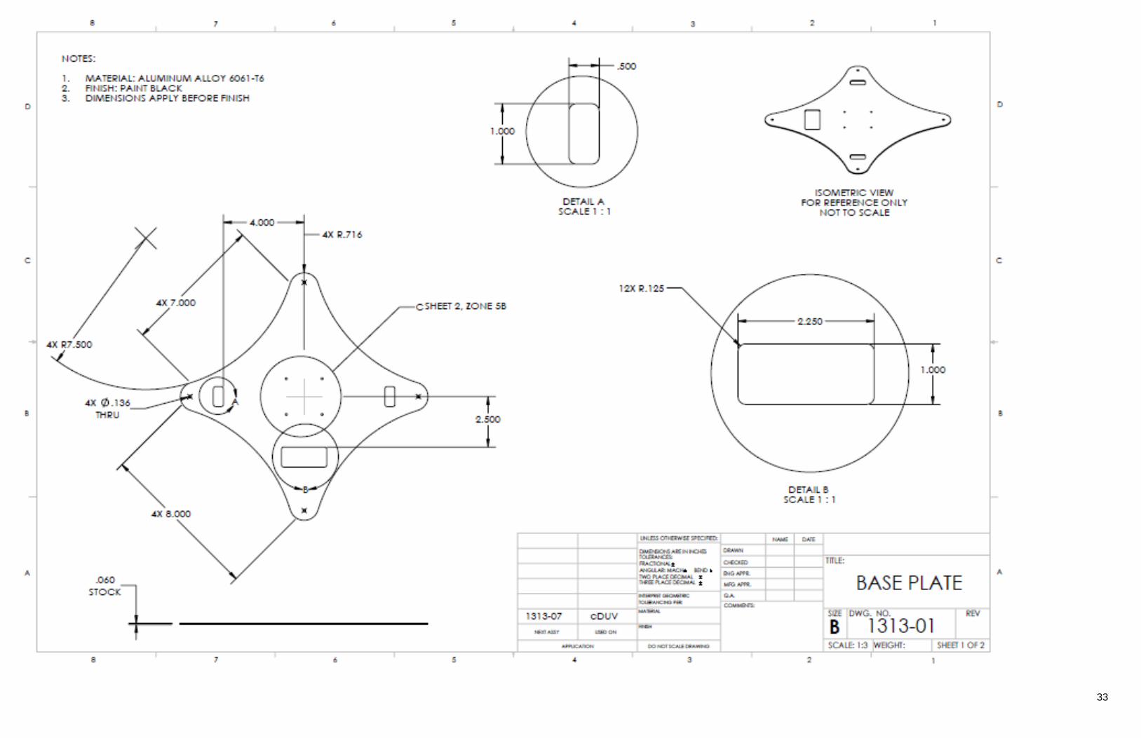
33
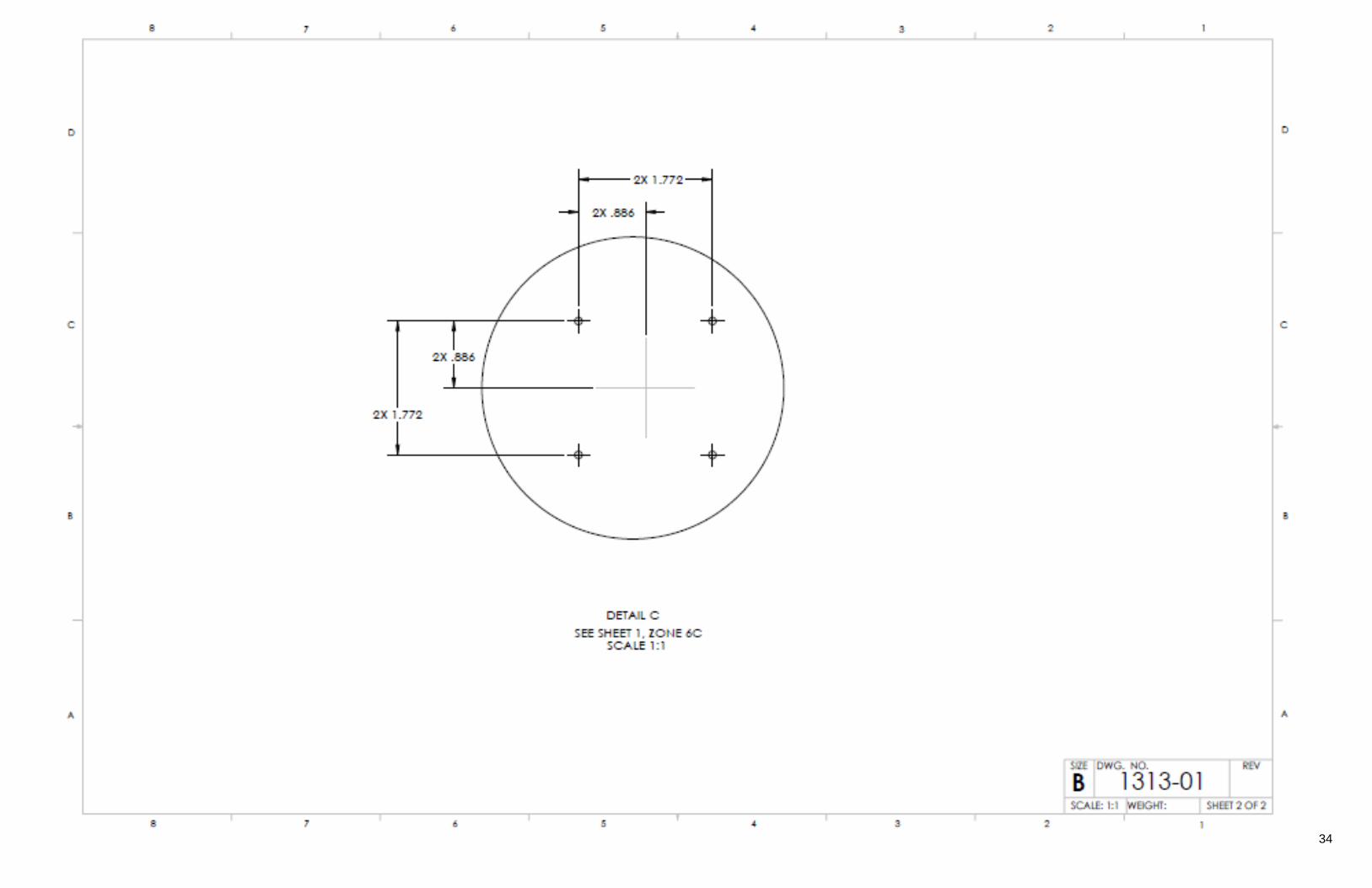
34
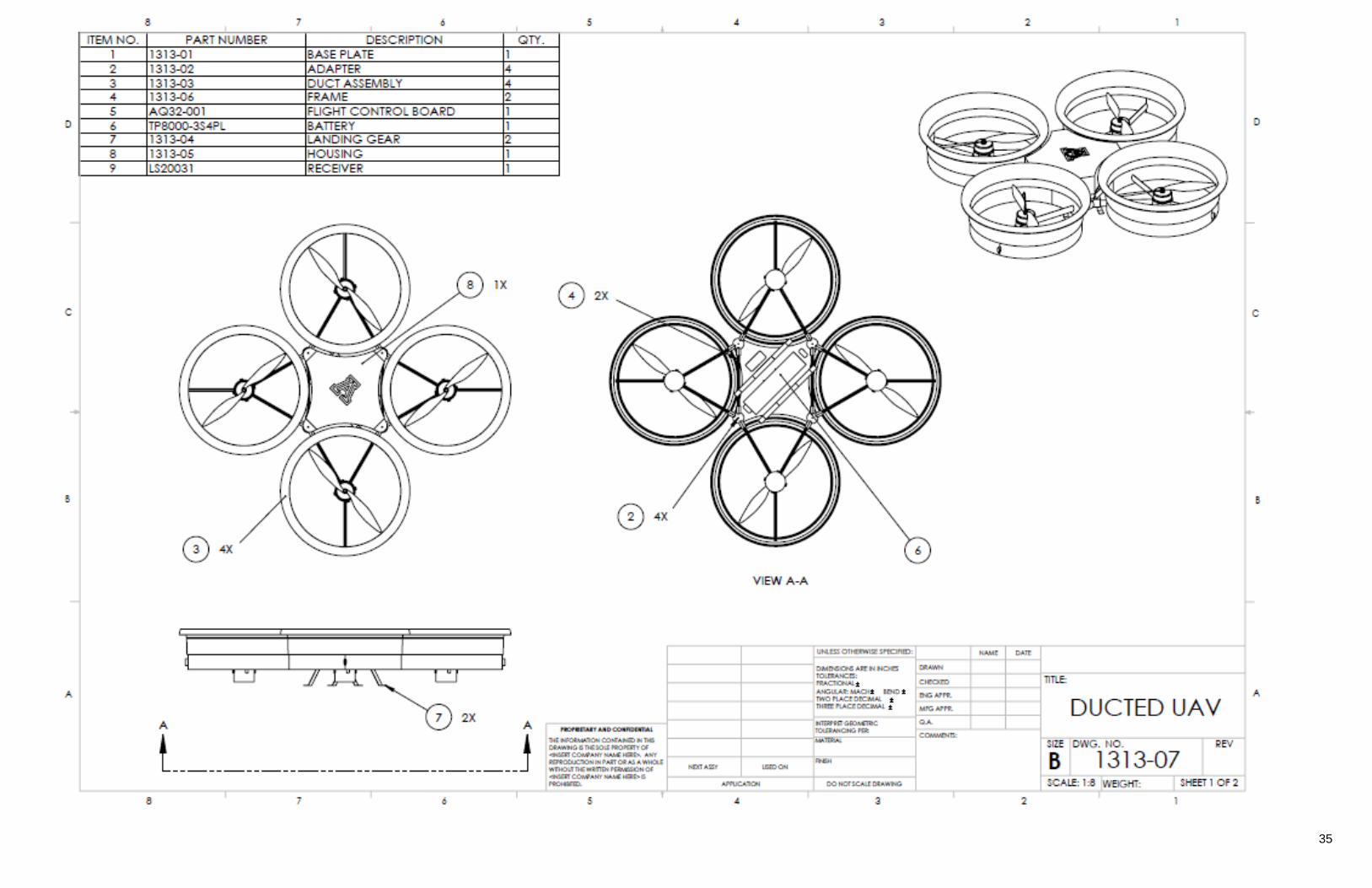
35
36
37
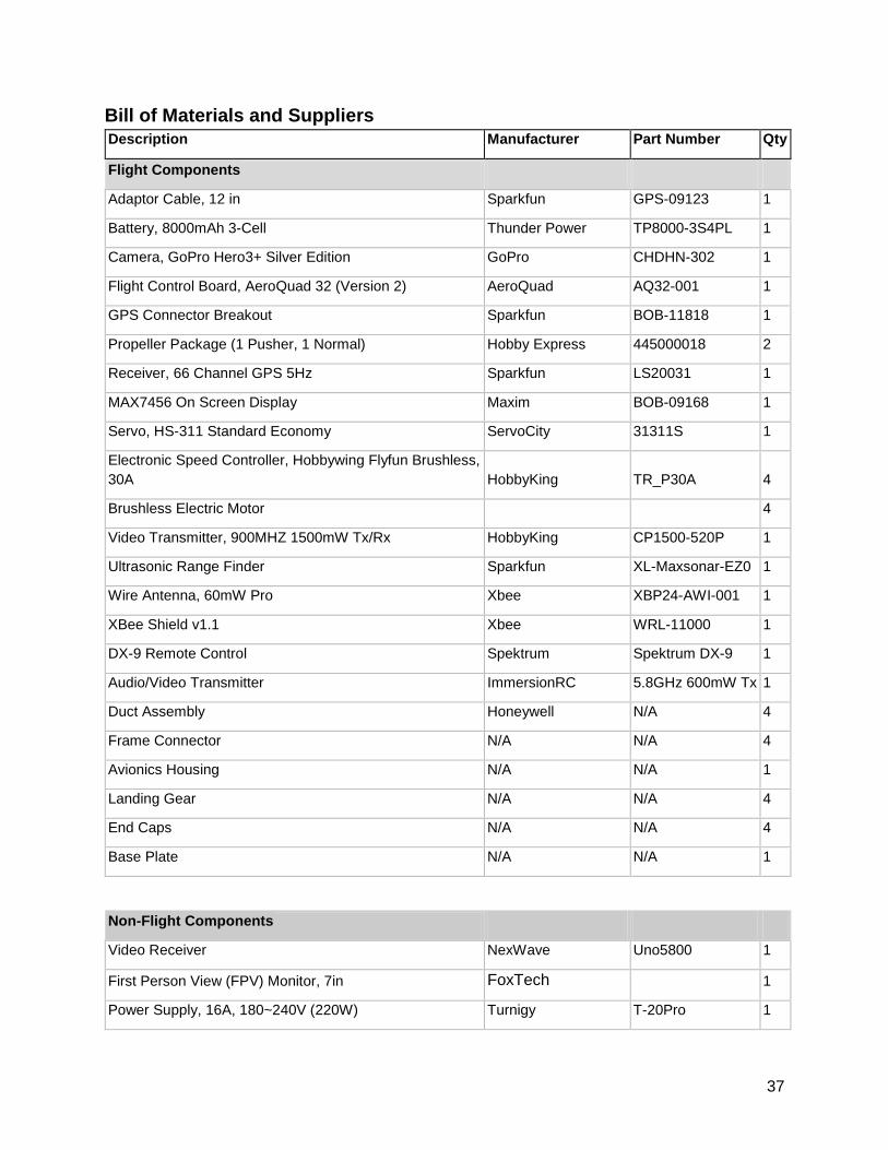
Bill of Materials and Suppliers
Description Manufacturer Part Number Qty
Flight Components
Adaptor Cable, 12 in Sparkfun GPS-09123 1
Battery, 8000mAh 3-Cell Thunder Power TP8000-3S4PL 1
Camera, GoPro Hero3+ Silver Edition GoPro CHDHN-302 1
Flight Control Board, AeroQuad 32 (Version 2) AeroQuad AQ32-001 1
GPS Connector Breakout Sparkfun BOB-11818 1
Propeller Package (1 Pusher, 1 Normal) Hobby Express 445000018 2
Receiver, 66 Channel GPS 5Hz Sparkfun LS20031 1
MAX7456 On Screen Display Maxim BOB-09168 1
Servo, HS-311 Standard Economy ServoCity 31311S 1
Electronic Speed Controller, Hobbywing Flyfun Brushless,
30A HobbyKing TR_P30A 4
Brushless Electric Motor 4
Video Transmitter, 900MHZ 1500mW Tx/Rx HobbyKing CP1500-520P 1
Ultrasonic Range Finder Sparkfun XL-Maxsonar-EZ0 1
Wire Antenna, 60mW Pro Xbee XBP24-AWI-001 1
XBee Shield v1.1 Xbee WRL-11000 1
DX-9 Remote Control Spektrum Spektrum DX-9 1
Audio/Video Transmitter ImmersionRC 5.8GHz 600mW Tx 1
Duct Assembly Honeywell N/A 4
Frame Connector N/A N/A 4
Avionics Housing N/A N/A 1
Landing Gear N/A N/A 4
End Caps N/A N/A 4
Base Plate N/A N/A 1
Non-Flight Components
Video Receiver NexWave Uno5800 1
First Person View (FPV) Monitor, 7in FoxTech 1
Power Supply, 16A, 180~240V (220W) Turnigy T-20Pro 1
38
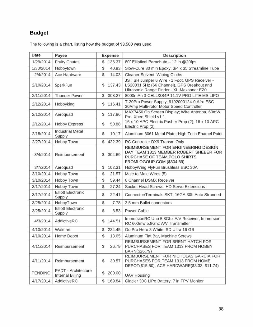
Budget
The following is a chart, listing how the budget of $3,500 was used.
Date Payee Expense Description
1/29/2014 Fruity Chutes $ 136.37 60” Elliptical Parachute – 12 lb @20fps
1/30/2014 Hobbytown $ 40.93 Slow-Cure 30 min Epoxy; 3/4 x 35 Streamline Tube
2/4/2014 Ace Hardware $ 14.03 Cleaner Solvent; Wiping Cloths
2/10/2014 SparkFun $ 137.43 JST SH Jumper 6 Wire - 1 Foot, GPS Receiver - LS20031 5Hz (66 Channel), GPS Breakout and Ultrasonic Range Finder - XL-Maxsonar EZ0
2/11/2014 Thunder Power $ 308.27 8000mAh 3-CELL/3S4P 11.1V PRO LITE MS LIPO
2/12/2014 Hobbyking $ 116.41 T-20Pro Power Supply; 9192000124-0 Afro ESC 30Amp Multi-rotor Motor Speed Controller
2/12/2014 Aeroquad $ 117.96 MAX7456 On Screen Display; Wire Antenna, 60mW Pro; Xbee Shield v1.1
2/12/2014 Hobby Express $ 50.88 16 x 10 APC Electric Pusher Prop (2); 16 x 10 APC Electric Prop (2)
2/18/2014 Industrial Metal Supply
$ 10.17 Aluminum 6061 Metal Plate; High Tech Enamel Paint
2/27/2014 Hobby Town $ 432.39 RC Controller DX9 Transm Only
3/4/2014 Reimbursement $ 304.69
REIMBURSEMENT FOR ENGINEERING DESIGN DAY TEAM 1313 MEMBER ROBERT SHEBER FOR PURCHASE OF TEAM POLO SHIRTS FROMLOGOUP.COM ($304.69)
3/7/2014 Aeroquad $ 102.31 HobbyWing FlyFun Brushless ESC 30A
3/10/2014 Hobby Town $ 21.57 Male to Male Wires (5)
3/10/2014 Hobby Town $ 59.44 6 Channel DSMX Receiver
3/17/2014 Hobby Town $ 27.24 Socket Head Screws; HD Servo Extensions
3/17/2014 Elliott Electronic Supply
$ 22.41 Connector/Terminals SKT; 16GA 30ft Auto Stranded
3/25/2014 HobbyTown $ 7.78 3.5 mm Bullet connectors
3/25/2014 Elliott Electronic Supply
$ 8.53 Power Cable
4/3/2014 AddictiveRC $ 144.51 ImmersionRC Uno 5.8Ghz A/V Receiver; Immersion RC 600mw 5.8Ghz A/V Transmitter
4/10/2014 Walmart $ 234.45 Go Pro Hero 3 White, SD Ultra 16 GB
4/10/2014 Home Depot $ 13.65 Aluminum Flat Bar, Machine Screws
4/11/2014 Reimbursement $ 26.79 REIMBURSEMENT FOR BRENT HATCH FOR PURCHASES FOR TEAM 1313 FROM HOBBY BARN($26.79)
4/11/2014 Reimbursement $ 30.57 REIMBURSEMENT FOR NICHOLAS GARCIA FOR PURCHASES FOR TEAM 1313 FROM HOME DEPOT($15.50), ACE HARDWARE($3.33, $11.74)
PENDING PADT - Architecture Internal Billing
$ 200.00 UAV Housing
4/17/2014 AddictiveRC $ 169.84 Glacier 30C LiPo Battery, 7 in FPV Monitor
39
4/24/2014 Ace Hardware $ 22.90
Enamel dark blue, white, red, Brush art 144 pc cyl asst (3), Nuts/Bolts/Nails (18), Nuts/Bolts/Nails(18), Nuts/Bolts/Nails (18), Nuts/Bolts/Nails (5), Nuts/Bolts/Nails (5)
4/29/2014 Walmart $ 64.60 Camera case; GoPro Grab Bag
4/29/2014 Walmart $ 2.15 Zip Ties
5/2/2014 Ace Hardware $ 3.24 nuts, bolts, nails
5/2/2014 Hobby Town $ 65.07 Servo Extension, DSMX Sportaire
5/5/2014 Fed Ex $ 44.65 Poster Printing
5/08/2014 Reimbursement $ 21.71 Hardware, electronics
Total Expenses $ 2,962.94
Remaining Budget $ 537.06
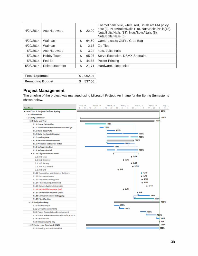
Project Management The timeline of the project was managed using Microsoft Project. An image for the Spring Semester is
shown below.
40
The project deliverables, including the completed UAV, reports, and presentations, were
delivered on time and as projected in the team’s Gantt chart. The build process of the UAV
was pushed back toward the end of the semester due to unforeseen complications with the
vehicle crashes and electronic failure. Despite these complications, the final product was
delivered on time.