abstract - nrao.edu · sertek schematic layout receivers. d.c. amp. prog. attn. 1 2k ir filter /...
TRANSCRIPT

Page 126 Fifth International Symposium on Space Terahertz Technology
A LOW NOISE 565435 GHz SIS WAVEGUIDE RECEIVER
J. W. Kooi l , C. K. Wa1ker2, H. G. LeDuc -3 , P. L. Schaffer', and T.G. Phillips'
1- Caltech Submillimeter ObservatoryDivision of Physics, Mathematics and Astronomy
California Institute of Technology, Pasadena, California 91125
2- University of Arizona, Tuscon, Arizona3- Center for Space Microelectronics Technology, Jet Propulsion Laboratory
Abstract
We report recent results on a 565-735 GHz SIS heterodyne receiver em-ploying a 0.36iim 2 Nb/AlOr/Nb SIS tunnel junction with high quality circularnon contacting backshort and E-plane tuners in a full height waveguide mount.No resonant tuning structures have been incorporated in the junction design atthis time, even though such structures are expected to help the performance ofthe receiver. The receiver operates to 735 GHz, well above the gap frequency ofniobium, 680 GHz. Typical receiver noise temperatures from 565-690 GHzrange from 160K to 230K with a best value of 185K DSB at 648 GHz, At730 GHz the receiver noise temperature has gradually increased from 230K to300K. The monotonic rise in noise temperature above 680 GHz is attributed to acombined effect of absorption loss in the niobium RF choke and antenna trans-mission lines and inability to tune out the large parasitic junction susceptance.With the mixer cooled from 4.3K to 2K the measured receiver noise tempera-tures decreased by approximately 15%, giving roughly 180K DSB from 660 to680 GHz. The receiver has a full 1 GHz IF passband and has been successfullyinstalled at the Caltech Submillimeter Observatory in Hawaii.
Introduction
A waveguide superconducting insulator superconducting (SIS) heterodynereceiver with a center frequency of 665 GI-Iz has been designed to take advan-tage of 600 to 730 GHz atmospheric window. The results discussed here wereachieved by using a 0.36pm 2 NbiAlO r/Nb tunnel junction in a full height rect-angular waveguide mixer [2] with two circular non- contacting tuning elements[3,4] and an integrated 1-2 GHz wide IF matching network.
It is clear that near quantum limited results (1] have been achieved by scal-ing SIS waveguide receivers to higher frequencies [5, 6]. Since a SIS junctionis essentially a sandwich of two superconducting electrodes separated by a verythin insulating material, 124), the geometric capacitance is appreciable, 75-85 fF/(pm2 ). To achieve a good RF match to the embedding impedance it isimportant to tune out the geometric capacitance of the junction. This becomes
Fifth International Symposium on Space Terahertz Technology Page 127
increasingly difficult as the operating frequency of the mixer is raised. For thispurpose waveguide receivers typically employ high 'Q' non-contacting backshortand E-plane tuners.
Recently advances in niobium thin film processing have permitted RFmatching on the chip itself, by means of lithographically produced tuning struc-tures, to tune out the parasitic capacitance. This technique has been very effec-tively used in both open structure devices [7,8] and waveguide mixers [9-14
Above the gap frequency, (2&h 680 GHz), the photon energy is largeenough to break Cooper-pairs in the superconductor causing large absorptionlosses in the material. Dierichs et al. [17] have measured intensities for loss-less resonant stubs and compared them against calculated intensities accordingto Mattis-Bardeen theory. These measurements did not indicate any resonancesabove the gap frequency of niobium. Calculations at 750 GHz show that the filmlosses of the niobium antenna mount and RF choke structure will increase fif-teen fold compared to below the gap. The transmission line losses are thereforesignificant, (> 40%/wavelength) [18], making it difficult to design a supercon-ducting matching network centered at 665 GHz with the required 20% band-width. To minimize the effect of the increased absorption losses near and abovethe gap frequency it was decided to improve the waveguide tuners and use un-tuned Nb/A10,/Nb tunnel junctions. This approach would ensure a broadband600-730 GHz SIS receiver provided of course that high quality non-contactingbackshorts were found that would meet our design objectives. The theory andperformance of these waveguide tuners will be elaborated on by Walker et al.[4] in a separate paper. However the results of preliminary scale model testingwill be presented in this paper.
NbIA10,1NbJunctionFabrication
The Nb/AlO r/Nb tunnel junctions were fabricated using a standard self-aligned lift-off trilayer process. The Nb/A10,/Nb trilayer was deposited in-situin a high vacuum deposition system with a base pressure of 4*10- 9 Torr, througha photoresist lift-off stencil (AZ5214) onto 50 pm thick quartz substrates. Thetrilayer remaining after lift-off formed the first half of the antenna/filter structure.The junction mesa was patterned using electron beam direct writing on a 120nm thick PMMA followed by evaporation of 50 nm chromium metal andsubsequent lift-off. Contact regions of the inlayer are then protected with aphotoresist stencil and the combined chromium/photoresist mask was used to etchthe junction in a parallel plate reactive ion etcher (RIE). The etch parameters were62%CC/2 F7 + 31%C.F.4 + 7%0,, 30 mTorr pressure, and .18 Watts/cm2 . Theelectrical isolation of the base electrode and subsequent wire layer are providedby thermal evaporation of 150 nm of SiO. The substrates were tilted and rotatedduring this operation. The chrome was lifted off using a commercial wet etch.The second half of the antenna was formed by a whole wafer deposition of Nb

Fromtelescope
tilted
1.5 GHz-0.5GHZ
SerteK
Schematic Layout Receivers.
D.C. Amp.
Prog. Attn.
1 2K IRFilter
/
Integrated matchingnetwom
I2K
I GHz LNAL-Band
• 39 cs8
10.0Vdc
Bias boo
: Pl'arle Wrier. -
tOde
Eccosoro
bea2 splitter Total Poweroutput.
so. tawdetector
• 44) dB
GHz
40 C • 0.356Hz
(IGHz OW)
To AOS
Page 128 Fifth International Symposium on Space Terahertz Technology
in the same vacuum system used for trilayer deposition and was patterned usingRIE. Tunnel junctions with areas down to 0.25 m2 were fabricated using thistechnique.
Receiver Description
Optics
Fig. I shows a block diagram of the 665 GHz receiver. The optics wasdesigned to give a 14 dB edge taper on the secondary mirror of the telescope.A 13 pm mylar beam splitter is mounted at 45° to the signal and local oscillatorbeams. The local oscillator's electric field is perpendicular to the plane ofincidence and about 5.7% of the radiation couples into the cryostat, the remainderis absorbed by a sheet of Eccosorb. The vacuum window is made out of 19ym
Fig. 1. Schematic layout of the receiver. Beam splitter, windowreflection, and IR filter losses at 665 GHz contribute about 65 Kelvinto the receiver noise temperature. The matching network is mountedin the mixer block and is followed by a two stage balanced HEIVITamplifier. The IF passband is 1.0 to 2.0 GHz.

tan(6) = (2)
Fifth International Symposium on Space Terahertz Technology Page 129
HR500/2S material manufactured for food packaging by Hercules Inc. [191It has a dielectric constant of 7. •,,d 2.6 and is a laminate of biaxially orientedpolypropylene with 2.5 pm layers of polyvinlidene chloride on both sides. Labo-ratory experiments have shown that the material has adequate strength to functionas a vacuum window for aperture diameters < 25 mm. Experiments indicate thatthe Hercules material is considerably more opaque to He 4 then 25 ,um m.ylarThe material is also expected to have a low permeability to water and atmo-spheric gasses. The infrared blocking filter on the 12 Kelvin window consistsof a one wavelength thick fluorogold disk. The mixer lens is made out of lowdensity polyethelene, with an approximate dielectric constant of 2.41 at 4.2Kambient temperature. The optics are designed to give a frequency independentillumination of the secondary (Goldsmith 1982). The low loss polyethylene lensis placed in the near field of the scaler feedhorn. Antenna pattern measurementsgive reasonably close agreement to the theoretically expected response.
Re f lectionandAbsorption Losses
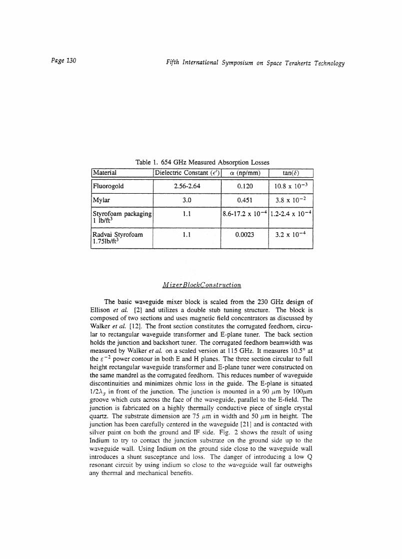
To better understand the noise contribution of the front-end optics of thereceiver, losses of different slabs of selected materials were measured at 654GHz. With the receiver tuned, the hot (293K) and cold (80K) IF power responsewas measured with or without a 'lossy' slab of material inserted in the beam.This procedure gave information on the effective 'cold' blackbody temperaturefrom which the total insertion loss of the material was computed. L includesboth the reflection and transmission losses of the sample.
Teff = L(Thot) — Lgeold (1)
Correcting for the reflection loss of the optically thick slab gives the trans-mission loss, a. Table 1 tabulates the dielectric constant and the loss tangent.The dielectric constant was obtained from the literature [201 and is assumed tobe relatively constant with frequency.
= transmission loss per unit wavelength.E l the real part of the dielectric constant.
Fifth International Symposium on Space Terahertz TechnologyPage 130
Table 1. 654 GHz Measured Absorption Losses
I Material Dielectric Constant (np/mm) tan(0)
Fluorogold 2.56-2.64 0.120■
10.8 x 10⁻³
Mylar 3.0 0.451,
3.8 x 10⁻²
Styrofoam packaging1 lb/ft3
1.1 8.6-17.2 x 10 -4 1.2-2.4 x 10⁻⁴
Radvai Styrofoam1.751b/fti
1.1 0.0023 3,2 x 10⁻⁴
Mixerer BlockC onstruction
The basic waveguide mixer block is scaled from the 230 GHz design ofEllison et al. [2] and utilizes a double stub tuning structure. The block iscomposed of two sections and uses magnetic field concentrators as discussed byWalker et al. [12], The front section constitutes the corrugated feedhom, circu-lar to rectangular waveg,uide transformer and E-plane tuner. The back sectionholds the junction and backshort tuner. The corrugated feedhom beamwidth wasmeasured by Walker et at on a scaled version at 115 GHz. It measures 10.5' atthe E 2 power contour in both E and H planes. The three section circular to fullheight rectangular waveguide transformer and E-plane tuner were constructed onthe same mandrel as the corrugated feedhom. This reduces number of waveguidediscontinuities and minimizes ohmic loss in the guide. The E-plane is situated1/2A 9 in front of the junction. The junction is mounted in a 90 by 100iumgroove which cuts across the face of the waveguide, parallel to the E-field. Thejunction is fabricated on a highly thermally conductive piece of single crystalquartz. The substrate dimension are 75 im in width and 50 pm in height. Thejunction has been carefully centered in the waveguide [21] and is contacted withsilver paint on both the ground and IF side. Fig. 2 shows the result of usingIndium to try to contact the junction substrate on the ground side up to thewaveguide wall. Using Indium on the ground side close to the waveguide wallintroduces a shunt susceptance and loss. The danger of introducing a low Qresonant circuit by using indium so close to the waveguide wall far outweighsany thermal and mechanical benefits.

700
600
500
(/)2 400
Ft: 300
200
635 640 645 650 655 660 665 670
Frequency (GHz)
675 680
-- No Indium- 30 Degrees
A 90 Degrees
Fifth International Symposium on Space Terahertz Technology Page 131
The thermal conductivity of the single crystal quartz is high enough to keepthe junction cold with only silver paint on both IF and ground sides of the RFchoke.
Fig. 2. Result of using indium close to the waveguide wall to provideboth mechanical support and a thermal and electrical short circuit.Data is taken with the same junction.
On the IF side the junction is contacted with a 25 pm Au wire soldered to a 1-2GHz wide IF matching network [22] which is mounted in the mixer block. Thematching network is designed to transform a 160 Ohm IF impedance to 50 Ohmand to provide a short to out of band signals up to 22 GHz. The latter is neededto avoid saturating the junction with unwanted out of band signals. The outputof the mixer block is directly connected to a 1-2 GHz balanced HEMT amplifierbased on work by Padin et al. [231. Any impedance mismatch between thematching network and low noise amplifier is absorbed by the amplifier's inputLange coupler. The RF choke structure is a 5 section Chebyshev bandpass filterdesigned to give maximum rejection (S11 < -25 dB) at 665 GHz and presentsa short circuit at the waveguide wall. Computer simulations of the RF chokeat 750 GHz indicate that reflection (S11) and transmission (S21) characteristicsare not severly effected above the gap frequency by the fifteen fold increase inniobium film loss (Fig. 7).

5.55.0(687)
4.54.0(550) (755)(618)
0CO —0.05 —1:3
—0.15—0.20—0.25 —
••■■• •■••■■■•• _.
3.5(480)
Page 132 Fifth International Symposium on Space Terahertz Technology
The 492 GHz receiver discussed by Walker et al. [12] has demonstrated9 dB of conversion loss at 492 GHz with a receiver temperature of 178 KDSB using an untuned 0.16p,m 2 Nb/A1OJNb SIS tunnel junction. This blockuses rectangular non-contacting tuners for both the backshort and E-plane asdescribed by Brewer and Raisdnen [24]. In order to ensure similar results at665 GHz, tuners with a higher VSWR are needed to tune out the increasedjunction susceptance. Kerr et al. [3] have further investigated the use of tunersfor the millimeter band. They found that tuners with multiple circular non-contacting sections have lower loss, and more smoothly varying reflection (S11)and phase characteristics than rectangular tuners. Fig. 3 shows the result ofscaled model measurements on both the circular and rectangular non-contactingtuner designs. Both tuners have four low and high impedance sections. Theinput reflection (S11) of the circular tuner is approximately -0.06dB (VSWR144). The VSWR of the rectangular non-contacting tuner with mylar tape is
Frequency (GHz)
Fig. 3. Scale model tuner measurement on both the input reflection co-efficient (S11) and phase response of the circular non-contacting tuner(solid line) and mylar covered rectangular tuner (dashed line). The res-onance occurs when the combined length of one high-low impedancesection approaches a quarter guide wavelength (Eq. 3). At 564 GHzthis begins to show up in the frequency response of the receiver.
78. At 665 GHz the VSWR of the rectangular tuner will degrade significantlybecause of increased dielectric losses in the mylar tape, resulting in higher mixerconversion loss. The poor phase characteristic of the reflection coefficient showsup as irregular receiver sensitivity across the frequency band. These problems,in theory, can be minimized by employing tuned SIS tunnel junctions although,

C t
17-1
Z--- 4 high/low impedance sections
Fifth International Symposium on Space Terahertz Technology Page 133
as has been mentioned, the microstrip loss problem has to be avoided. Carehas been taken in these model measurements to scale everything exactly to thedimensions in the actual mixer block. In the scale model the effective shortcircuit plane is located 10° behind the first dumbbell section. The tunerresponse degrades catastrophically when the first high-low section combinedlength (i t ) approaches a quarter guide wavelength. The resonant cutoff frequencycan be approximated by
fres= kV(7,4cry + (3)
•c is the cutoff frequency of the TE10 mode (431 GHz), k is (0.9-0.97) dependingon the number of sections and c is the speed of light. Walker et al. will elaboratemore on this in a separate paper [4].
The tuner itself consists of four beryllium copper concentric circular sec-tions that extend from a rectangular shaft which is carefully fit in the waveguide.Scale model measurements have indicated that the position of the tuner in thewaveguide is not critical as long as wall contact by the round sections is avoided.Fig. 4 shows a drawing of the backsort and E-plane tuners. The resonance oc-curs at 523 GHz which is starting to show up at 563 GHz (Fig. 7).
Ct
Fig. 4. Drawing of the 665 GHz circular non-contacting tuner. Thetuner has 8 dumbbell sections, each being A 0/4 long at the designfrequency. The waveguide to tuner clearance is 4 ym. To avoidelectrical contact with the waveguide walls it is important to coat thetuners with an insulator such as aluminum oxide.
Result sandD isms sion
The mixer uses a high quality 0.36 m2 Nb/A10,/Nb tunnel junction with acurrent density of 10kA/cm 2 , a sub...gap leakage current of 2.6/1A and a nor-mal state resistance R, of 50 Ohms. These characteristics allow the junction tobe efficiently coupled to both the RF embedding impedance and IT impedance
110
100—
90 -
80 -
70 -
60 -
50 —
40 -
30 -
20 -
10
0
2.0 3.0 4.0
Bias Voltage (mV)
Page 134 Fifth International Symposium on Space Terahertz Technology
(160C2), for which the matching network was designed. The junction has a(.421Z,C j product of approximately 5.9. C 3 is the geometric junction capacitanceand is 28 fF for this junction. Different junctions with either higher currentdensity (larger sub-gap leakage) or smaller areas (larger normal state resistance)have been tested but did not perform quite as well as the 5012 036pm 2 tun-nel junction. The junction is fabricated on a 50Am thick single crystal quartzsubstrate.
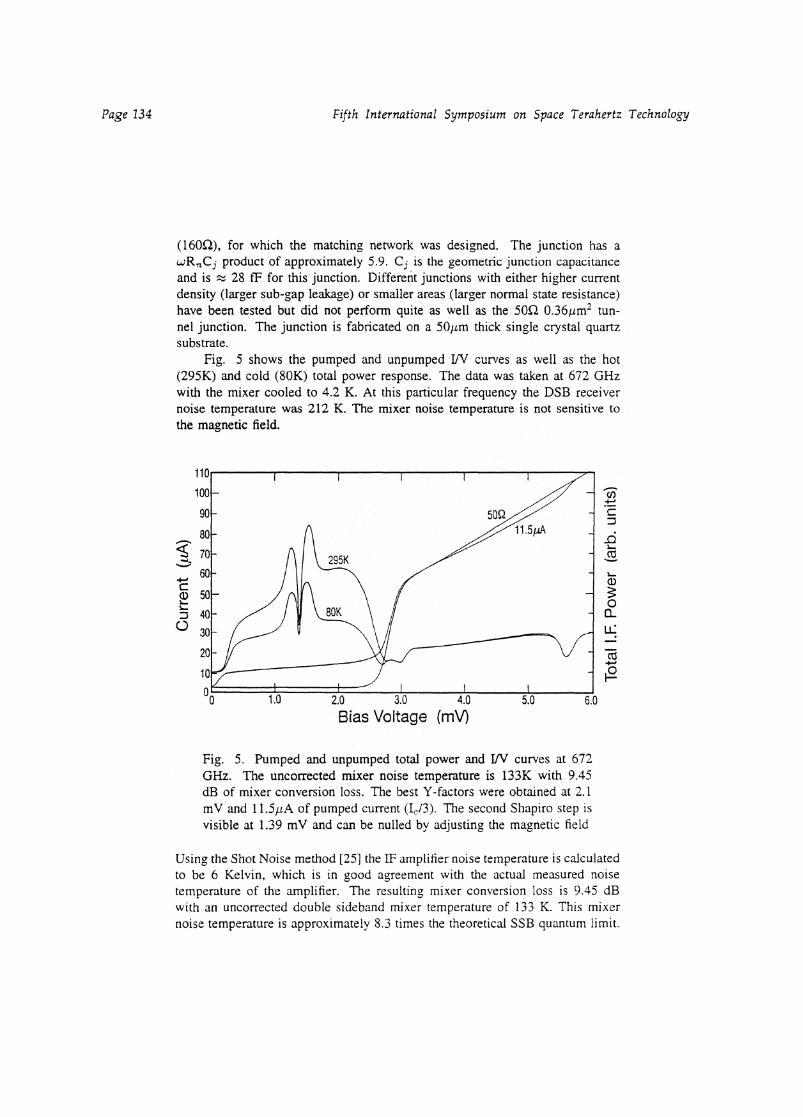
Fig. 5 shows the pumped and unpumped 1N curves as well as the hot(295K) and cold (80K) total power response. The data was taken at 672 GHzwith the mixer cooled to 4.2 K. At this particular frequency the DSB receivernoise temperature was 212 K. The mixer noise temperature is not sensitive tothe magnetic field.
Fig. 5. Pumped and unpumped total power and 1/V curves at 672GHz. The uncorrected mixer noise temperature is 133K with 9.45dB of mixer conversion loss. The best Y-factors were obtained at 2.1mV and 11.5yA of pumped current (I c/3). The second Shapiro step isvisible at 1.39 mV and can be nulled by adjusting the magnetic field
Using the Shot Noise method [25] the IF amplifier noise temperature is calculatedto be 6 Kelvin, which is in good agreement with the actual measured noisetemperature of the amplifier. The resulting mixer conversion loss is 9.45 dBwith an uncorrected double sideband mixer temperature of 133 K. This mixernoise temperature is approximately 8.3 times the theoretical SSB quantum limit.

400
375
Ca 350(i)0 325
300
z 275T.(1) 250
a) 225
• 200cn•....O 175
150
125
= "-Gain
Mixer
-10
-11
-12
-13
-8
-9
1.6 1.8 2.0 2.2 2.4
Bias Voltage (mV)
1001.4 2.6
-142.8
Fifth International Symposium on Space Terahertz Technology Page 135
Cooling the mixer block to 2K improved the conversion loss by 1 dB and resultedin a receiver temperature of 180K and mixer noise temperature of 110K. Themost likely cause of the improved mixer conversion loss and lower mixer noisetemperature is the sharpening of the gap and reduction in the subgap leakagecurrent. At 672 GHz the quasi-particle step width is 2.78 mV which is justbelow the band gap of niobium 2.85 mV). Just above the gap frequency ofniobium, 690 GHz, the receiver noise temperature was ,•:9, 230K and graduallyincreases to 300K at 730 GHz inspite of a factor of 16 higher absorbtion loss inthe nioium film as compared to the loss below the gap frequency. The effect ofdispersion loss in an untuned junction is relatively small because there are nohigh Q lossy niobium tuning structures with large current concetrations present.Another possible reason for the increase in mixer conversion loss above thegap is the inability to tune out the increasing parasitic junction susceptance.Adjusting the magnetic field on the junction had no significant effect on thereceiver noise temperature.
Fig. 6. Noise temperature and mixer conversion gain as a functionof bias voltage at 654 GHz. The mixer temperature corrected forbeamsplitter & window reflections is 89K.

500
450 —
400 —
"350 —
‘3* 300 —
115.250 —
Ea) 200 -a
4)u) 150 —0 aZ 100 —
50 —
Page 136 Fifth International Symposium on Space Terahertz Technology
Figure 6 shows the receiver noise temperature as a function of bias voltage. Thebest place to bias the mixer is between 2.1 and 2.25 mV. Similar results areobserved with the 230-, 345-, and 492 Nb/A10 z/Nb SIS quasi-particle mixers.The optimum LO drive is Ic/3, where I, is the critical current of the junction,35yA. Figure 7 shows the frequency response of the receiver from 560 to 738GHz. The quality of the circular non-contacting tuners is apparent from the wellbehaved frequency response of the mixer.
0 Tr —50560 580 600 620 640 660 680 700 720 740
Frequency ( GHz)
Fig. 7. Frequency response of the receiver from 560-738 GHz. Theincrease of noise temperature at 564 GHz is likely caused by the tunerresonance (Fig. 3). Cooling the mixer to 2K improved the receivernoise temperature by 15%
All measurements from 564-680 GHz were made with a 13pm beamsplitter.Data from 690-738 GHz were taken with a 20pm Hercules beamsplitter whichhas a reflection loss of 10.0% at 700 GHz. The quoted 690-738 GHz noisetemperatures are referred to a 13prn beamsplitter.
Fifth International Symposium on Space Terahertz Technology Page 137
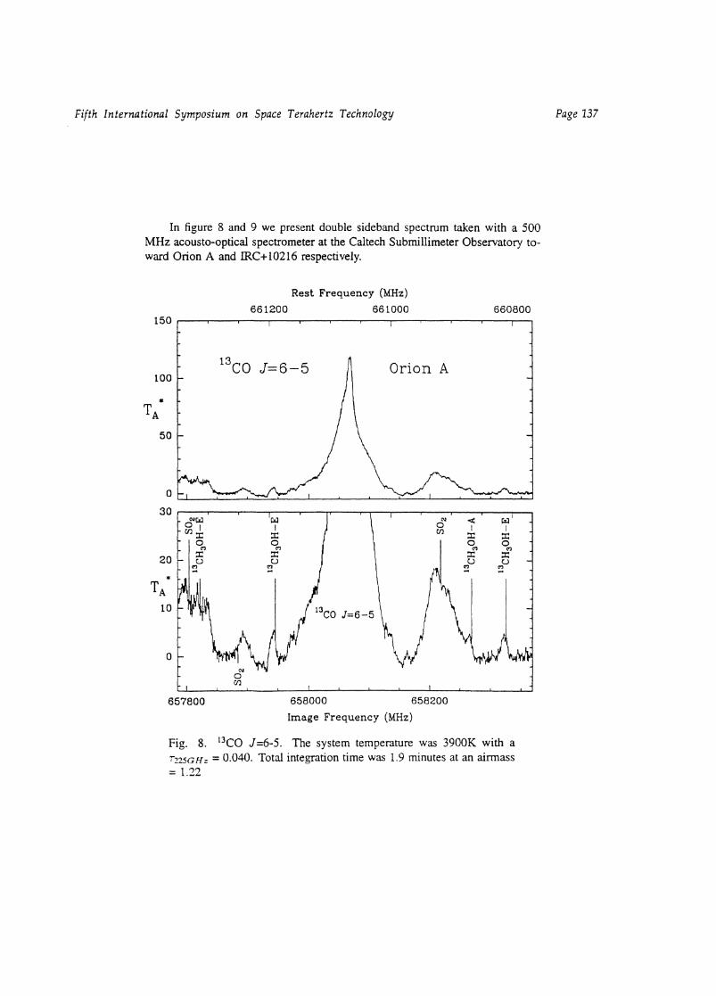
In figure 8 and 9 we present double sideband spectrum taken with a 500MHz acousto-optical spectrometer at the Caltech Submillimeter Observatory to-ward Orion A and ER.C+10216 respectively.
Rest Frequency (MHz)661200 661000 660800
150
100
TA
50
30
0
13
c0 J=6-5 Orion A
20
TA
10
657800 658000 658200
Image Frequency (MHz)
Fig. 8. 13C0 J=6-5. The system temperature was 3900K with a7-225Gliz = 0.040. Total integration time was 1.9 minutes at an airmass= 1./2

1 T'3C0(6-5) 661.1 -
1 0
—80 —60 —40 —20
0= 1
—60 —40 —20 0 20 —60 —40 —20 0 20
—60 —40 —20 0 20VuR (km/sec)
—60 —40 —20 0(km/sec)
20 —50(km/sec)
20
15
7; 1 0o-P
5
CO(6-5) 691.5
40
20
r708.9
20
1 0
Page 138 Fifth International Symposium on Space Terahertz Technology
The measured main beam efficiency at these frequencies is 30%, but due tothe small beam size (11 arcsec) and the extended nature of the source thesespectra are corrected for the 60% coupling efficiency to the Moon. Some of themolecular transitions have been identified in both upper and lower sidebands asindicated by the label.
Figure 9. Spectral line survey of the most prominent molecular emission linesin IRC+10216 [26]. System noise temperatures varied from 5000-7000K with1.0 - 1.5mm precipitable H 20. Total integration time in all instances was lessthan 5 minutes.
ConclusionA 665 GHz SIS heterodyne receiver has been developed to take advan-
tage of the 600-730 GHz atmospheric window. The receiver has a full 1 GHzIF bandwidth and has been under test at the Caltech Submillimeter Observa-tory in Hawaii since August, 1993. The mixer employs an untuned 0.36,m2NIVAIO r/Nb tunnel junction with a current density of 10 kAicm2 . No ad-verse effect on the mixer conversion loss or noise temperature is seen up to thegap frequency of niobium (680 GHz). Above 680 GHz however the measuredmixer conversion loss increases by 0.028dB/GHz. This increase is most likelycaused by a combination of niobium loss and inability to tune out the large para-sitic junction susceptance. To minimize the dispersion loss effect of the niobiumfilm above the gap no tuning structures were incorporated on the junction. Itis expected that tuned junctions will improve the performance below the gap

Fifth International Symposium on Space Terahertz Technology Page 139
frequency but will suffer from a much larger increase in conversion loss abovethe gap due to the high currents in the lossy tuning elements. The mixer blockuses backshort and E-plane tuners with four circular non-contacting dumbbellsections. Scale model measurements of these tuners indicate an improved phaseand VSWR over rectangular non-contacting tuners. Their superior performanceis reflected in the flat frequency response of the mixer. Receiver noise tempera-tures are 205K ± 20K DSB dipping to 185K at 648 GHz. The mixer conversionloss varies from 9-11 dB and is comparable to the 492 GHz waveguide receiverinstalled at the CSO in September 1991 [12]. When the mixer was cooled to2K the measured receiver noise temperatures decreased by approximately 15%which is similar to the result obtained on a 230 GHz waveguide receiver [22].Pumping on the mixer resulted in a measured DSB receiver noise temperatureof approximately 180 Kelvin from 660 to 680 GHz.
Acknowledgments
We wish to thank Jonas Zmuidzinas, Rob Schoelkopf, Todd Groesbeck,Man Chan, Dominic Benford, Todd Hunter, Ken Young, and Tony Kerr forhelpful discussions. We also like to thank John Carlstrom for supplying thehigh frequency Gunn Oscillators and Keith Horvath at Custom Microwave forhis skill in machining the mixer block to tolerances of < 2iim. Work on highfrequency receivers at Caltech is supported in part by NASA grant° NAGW-107and NSF grant° AST-9015755.
References
[1] J.R. Tucker and Mi. Feldman, "Quantum Detection at Millimeter Wave-length," Rev. Mod. Phys. 57, 1055-1113, 1985
[2] B.N. Ellison and R.E. Miller, "A Low Noise 230 GHz SIS Receiver," Int.J. IR and MM Waves 8, 609-625, 1987
[3} A. R. Kerr, "An Adjustable Short-Circuit for Millimeter Waveguides," Elec-tronics Division Internal Report No. 280, National Radio Astronomy Ob-servatory, Charlottesville, VA 22903, July 1988.
[4] C. K. Walker, J. W. Kooi, in preparation.[5] R. Blundell and C. E. Tong, "Submillimeter Receivers for Radio Astron-
omy," Proc. IEEE, vol. 80, no. 11, pp. 1702-1720, Nov. 1992.[6] M. J. Wengler, "Submillimeter-wave detection with superconducting tunnel
diodes," Proc. IEEE, vol. 80, no. 11, pp. 1810-1826, Nov. 1992.[7] J. Zmuidzinas, H.G. Leduc, J.A. Stern, and S.R. Cypher, "Two-junction
tuning circuits for submillimeter SIS mixers," IEEE accepted.[Si T.H. BUttgenbach, H.G. LeDuc, P.D. Maker, T.G. Phillips, "A fixed tuned
broadband matching structure for submillimeter receivers," IEEE Trans.Applied Supercond., Vol. 2, No. 3, pp. 165-175, September 1992.

Page 140 Fifth International Symposium on Space Terahertz Technology
[9] A.R. Kerr and S.K. Pan, "Integrated tuning elements for SIS mixers," Mt.J. IR and MM Waves, vol. 9, No. 2, pp. 203-212, 1988.
[10] A. Karpov, M. Carter, B. Lazereff, D. Billon-Peron and K.H. Gundlach,"Modelling and performance of Nb SIS mixers in the 1.3mm and 0.8mmbands," in proc. Third Intl. Symp. Space Terahertz Technology, pp. 244-250, March 1992.
[11] J. W. Kooi, M. Chan, B. Bumble, T. G. Phillips, "A low noise 345 GHzwaveguide receiver employing a tuned 0.50 ism 2 Nb/A10,/Nb tunnel junc-tion," in preparation.
[12] C. K. Walker, J. W. Kooi, M. Chan, H. G. Leduc, P.L. Schaffer, J.E. Carl-strom, and T.G. Phillips, "A Low-noise 492 GHz SIS waveguide receiver,"Mt. J. IR and MM Waves, vol. 13, pp. 785-798, June 1992.
[13} G. de Lange, C.E. Honingh, M.M.T.M. Dierichs, H.H.A. Schaeffer, J.J.Kuipers, R.A. Panhuyzen, T.M. Klapwijk, H. van de Stack, M.W.M. deGraauw, E. Armandillo, "Quantum limited responsivity of a Nb/Al203/NbSIS waveguide mixer at 460 GHz," in proc. Fourth Intl. Symp. SpaceTerahertz Technology (UCLA), 1993.
[14] G. de Lange, C.E. Honingh, J.J. Kuipers, H.H.A. Schaeffer, R.A. Pan-huyzen, T.M. Klapwijk, H. van de Stadt, M.W.M. de Graauw, Hetero-dyne mixing with Nb tunnel junctions at 720 and 840 GHz", submitted toApplied Physics letters.
[15] M. Salez, P. Febre, W.R. McGrath, B. Bumble, H.G. LeDuc, "An SISWaveguide Heterodyne Recever for 600 GHz- 635GHz," Intl. J. IR andMM Waves, Vol 15, No.2, Feb. 1994.
[16} K.F. Schuster, A.I. baths, K.H. Gundlach, "A 691 GHz SIS Receiver forRadio Astronomy," Intl. J. IR and MM Waves, Vol. 14, no. 10, Oct 1993.
[171 M.M.T.M. Dierichs, C.E. Honigh, R.E. Honingh, R.A. Panhuyzen, B.J.Feenstra, A. Skalare, J.J. Wijnbergen, H. v.d. Stadt, and Th. de Graauw,"Evaluation of integrated tuning elements with SIS devices," IEEE trans.Microwaves Theory and Techniques, Vol. 41, No. 4, April 1993.
[18] R.L. Kautz, Journal of Applied Physics 49, 308 (1978).
[19] A.R. Kerr, N.J. Bailey, D.E. Boyd and N. Homer, "A study of materials fora broadband millimeter-wave quasi-optical vacuum window," ElectronicsDivision Internal Report No. 292, National Radio Astronomy Observatory,Charlottesville, VA 22903, August 1992.
[201 J. W. Lamb, "Infrared filters for cryogenic receivers," Electronics DivisionInternal Report No. 290, National Radio Astronomy Observatory, Char-lottesville, VA 22903, April 1992.
[21] T.H. aittgenbach, T.D. Groesbeck, and B. Ellison, "A scale mixer modelfor SIS waveguide receivers," Intl. J. Infrared and Millimeter Waves, vol.11, no. 1, 1990.
Fifth International Symposium on Space Terahertz Technology Page 141
[22] J. W. Kooi, M. Chan, T.G. Phillips, B. Bumble, and H. G. Leduc, "A lownoise 230 GHz heterodyne receiver employing 0.25 pm2 area Nb/AlOr/Nbtunnel junctions," IEEE trans. Microwaves Theory and Techniques, Vol.40, pp. 812-815, May 1992.
[23] S. Padin, G. Ortiz. "A Cooled 1-2 GHz Balanced HEMT Amplifier," IEEE,Microwave Theory and Techniques, Vol 39, No 7, pp 1239-1243, 1991.
[24] M.K. Brewer, and A.V. Raisanen, IEEE Trans. Microwave Theory andTechniques, Vol. 30, pp. 708, 1982.
[251 D.P. Woody, R.E. Miller and M.J. Wengler, "85-115 GHz Receivers forRadio Astronomy," IEEE trans. Microwaves Theory and Techniques, Vol.MTT-33, 1985, pp. 90-95
[26] K. Young, T.D. Groesbeck, A.E. Schinkel and G.R. Knapp, "Astro-PhysicalJournal Letters, in preparation.